EP3306380A1 - Glasses-type electronic device - Google Patents
Glasses-type electronic device Download PDFInfo
- Publication number
- EP3306380A1 EP3306380A1 EP16803288.6A EP16803288A EP3306380A1 EP 3306380 A1 EP3306380 A1 EP 3306380A1 EP 16803288 A EP16803288 A EP 16803288A EP 3306380 A1 EP3306380 A1 EP 3306380A1
- Authority
- EP
- European Patent Office
- Prior art keywords
- fpc
- compartment
- printed circuit
- flexible printed
- glasses
- Prior art date
- Legal status (The legal status is an assumption and is not a legal conclusion. Google has not performed a legal analysis and makes no representation as to the accuracy of the status listed.)
- Withdrawn
Links
Images






Classifications
-
- G—PHYSICS
- G02—OPTICS
- G02C—SPECTACLES; SUNGLASSES OR GOGGLES INSOFAR AS THEY HAVE THE SAME FEATURES AS SPECTACLES; CONTACT LENSES
- G02C5/00—Constructions of non-optical parts
- G02C5/14—Side-members
-
- A—HUMAN NECESSITIES
- A61—MEDICAL OR VETERINARY SCIENCE; HYGIENE
- A61B—DIAGNOSIS; SURGERY; IDENTIFICATION
- A61B5/00—Measuring for diagnostic purposes; Identification of persons
- A61B5/24—Detecting, measuring or recording bioelectric or biomagnetic signals of the body or parts thereof
- A61B5/25—Bioelectric electrodes therefor
- A61B5/279—Bioelectric electrodes therefor specially adapted for particular uses
- A61B5/297—Bioelectric electrodes therefor specially adapted for particular uses for electrooculography [EOG]: for electroretinography [ERG]
-
- A—HUMAN NECESSITIES
- A61—MEDICAL OR VETERINARY SCIENCE; HYGIENE
- A61B—DIAGNOSIS; SURGERY; IDENTIFICATION
- A61B3/00—Apparatus for testing the eyes; Instruments for examining the eyes
- A61B3/10—Objective types, i.e. instruments for examining the eyes independent of the patients' perceptions or reactions
- A61B3/113—Objective types, i.e. instruments for examining the eyes independent of the patients' perceptions or reactions for determining or recording eye movement
-
- A—HUMAN NECESSITIES
- A61—MEDICAL OR VETERINARY SCIENCE; HYGIENE
- A61B—DIAGNOSIS; SURGERY; IDENTIFICATION
- A61B5/00—Measuring for diagnostic purposes; Identification of persons
- A61B5/24—Detecting, measuring or recording bioelectric or biomagnetic signals of the body or parts thereof
- A61B5/25—Bioelectric electrodes therefor
- A61B5/251—Means for maintaining electrode contact with the body
- A61B5/256—Wearable electrodes, e.g. having straps or bands
-
- A—HUMAN NECESSITIES
- A61—MEDICAL OR VETERINARY SCIENCE; HYGIENE
- A61B—DIAGNOSIS; SURGERY; IDENTIFICATION
- A61B5/00—Measuring for diagnostic purposes; Identification of persons
- A61B5/68—Arrangements of detecting, measuring or recording means, e.g. sensors, in relation to patient
- A61B5/6801—Arrangements of detecting, measuring or recording means, e.g. sensors, in relation to patient specially adapted to be attached to or worn on the body surface
- A61B5/6802—Sensor mounted on worn items
- A61B5/6803—Head-worn items, e.g. helmets, masks, headphones or goggles
-
- G—PHYSICS
- G02—OPTICS
- G02C—SPECTACLES; SUNGLASSES OR GOGGLES INSOFAR AS THEY HAVE THE SAME FEATURES AS SPECTACLES; CONTACT LENSES
- G02C11/00—Non-optical adjuncts; Attachment thereof
- G02C11/10—Electronic devices other than hearing aids
-
- G—PHYSICS
- G02—OPTICS
- G02C—SPECTACLES; SUNGLASSES OR GOGGLES INSOFAR AS THEY HAVE THE SAME FEATURES AS SPECTACLES; CONTACT LENSES
- G02C5/00—Constructions of non-optical parts
- G02C5/02—Bridges; Browbars; Intermediate bars
-
- G—PHYSICS
- G02—OPTICS
- G02C—SPECTACLES; SUNGLASSES OR GOGGLES INSOFAR AS THEY HAVE THE SAME FEATURES AS SPECTACLES; CONTACT LENSES
- G02C5/00—Constructions of non-optical parts
- G02C5/22—Hinges
-
- A—HUMAN NECESSITIES
- A61—MEDICAL OR VETERINARY SCIENCE; HYGIENE
- A61B—DIAGNOSIS; SURGERY; IDENTIFICATION
- A61B2562/00—Details of sensors; Constructional details of sensor housings or probes; Accessories for sensors
- A61B2562/02—Details of sensors specially adapted for in-vivo measurements
- A61B2562/0219—Inertial sensors, e.g. accelerometers, gyroscopes, tilt switches
-
- A—HUMAN NECESSITIES
- A61—MEDICAL OR VETERINARY SCIENCE; HYGIENE
- A61B—DIAGNOSIS; SURGERY; IDENTIFICATION
- A61B5/00—Measuring for diagnostic purposes; Identification of persons
- A61B5/103—Measuring devices for testing the shape, pattern, colour, size or movement of the body or parts thereof, for diagnostic purposes
- A61B5/11—Measuring movement of the entire body or parts thereof, e.g. head or hand tremor or mobility of a limb
-
- A—HUMAN NECESSITIES
- A61—MEDICAL OR VETERINARY SCIENCE; HYGIENE
- A61B—DIAGNOSIS; SURGERY; IDENTIFICATION
- A61B5/00—Measuring for diagnostic purposes; Identification of persons
- A61B5/68—Arrangements of detecting, measuring or recording means, e.g. sensors, in relation to patient
- A61B5/6801—Arrangements of detecting, measuring or recording means, e.g. sensors, in relation to patient specially adapted to be attached to or worn on the body surface
- A61B5/6844—Monitoring or controlling distance between sensor and tissue
Definitions
- the present invention relates to a glasses-shaped electronic device to be mounted on the head of a human to detect characteristics of the human.
- Electrodermal activity has been known as parameters indicating human psychological activity and physical conditions.
- the potentials of the skin of the human are detected, so that the characteristics of the human can be detected.
- Glasses-shaped electronic devices are currently required to detect the potentials of the skin of a human, particularly, the potentials (eye potentials) of the surface of the nose so that a variety of biological information about the human can be obtained based on the potentials. Examples of these devices include a device disclosed in PTL 1.
- This device includes a pair of electrodes for detecting eye potentials such that the electrodes are arranged on the surfaces of nose pads of an eyeglass frame.
- the device further includes an electrode for detecting an eye potential such that the electrode is disposed on the surface of a bridge of the eyeglass frame.
- the eye potentials detected by the electrodes are transmitted as electrooculogram signals to an external electrooculogram processing unit connected to the electrodes by electric wiring lines, serving as conductors.
- the processing unit processes the signals.
- the electric wiring lines can be arranged on the outside of the eyeglass frame. If the electric wiring lines are exposed on the outside of the eyeglass frame, a user may touch the electric wiring lines with, for example, his or her finger, when using the device. The electric wiring lines may be broken.
- the electric wiring lines can be received in the eyeglass frame, it is difficult in view of structure to arrange the electric wiring lines in the eyeglass frame because the eyeglass frame is thin. A wiring operation is also complicated. When the electric wiring lines are arranged inside the eyeglass frame, it is necessary to maintain stable connection between electronic components included in the device.
- the present invention has been made in view of such circumstances and aims to provide a glasses-shaped electronic device having conductor wiring readily achieved in an eyeglass frame and capable of maintaining stable connection between electronic components included in the device without any possibility of a break in a conductor.
- a glasses-shaped electronic device includes an eyeglass frame including a bridge, rims, hinges, and temples, and a flexible printed circuit having deformable bends.
- the eyeglass frame has a flexible printed circuit compartment extending through the bridge, the rims, the hinges, and the temples. The compartment accommodates the flexible printed circuit.
- the eyeglass frame has cavities arranged adjacent to the compartment in the hinges. The cavities accommodate the deformable bends of the flexible printed circuit.
- Such a configuration facilitates conductor wiring in the eyeglass frame and can maintain stable connection between electronic components included in the device without any possibility of a break in a conductor.
- the flexible printed circuit compartment may be defined between two portions into which each of the bridge, the rims, the hinges, and the temples is divided.
- Such a configuration enables the flexible printed circuit to be readily received in the eyeglass frame.
- the flexible printed circuit may be held in the compartment in the rims such that a main surface of the flexible printed circuit extends substantially horizontally.
- parts of the flexible printed circuit extending from the deformable bends to the hinges are twisted by substantially 90° in the compartment adjacent to the hinges and the flexible printed circuit is held in the compartment in the temples such that the main surface extends substantially vertically.
- parts of the flexible printed circuit adjacent to the bridge are twisted by substantially 90° in the compartment in the rims and the flexible printed circuit is held in the compartment in the bridge such that the main surface extends substantially vertically.
- Such a configuration allows the single flexible printed circuit to extend through the hinges, the rims, and the bridge without being exposed on the outside of the glasses-shaped electronic device.
- the glasses-shaped electronic device with excellent design quality can be provided.
- the glasses-shaped electronic device may further include positioning members arranged in the compartment in the rims and mounted adjacent to the hinges.
- the positioning members support the flexible printed circuit such that the main surface is parallel to the rims.
- Such a configuration enables the flexible printed circuit to be received and positioned in the thin rims.
- each of the positioning members may include a marker exposed at a front surface of the corresponding one of the rims.
- Such a configuration allows the markers to serve as references for measuring, for example, parallelism, to detect a performance characteristic, such as the posture, motion, or vibration of a user.
- the glasses-shaped electronic device may further include a human characteristic detecting unit disposed in the bridge and configured to detect an eye potential while being in contact with a human nose.
- the flexible printed circuit may extend to right and left temple tips of the eyeglass frame such that the bridge of the eyeglass frame corresponds to middle part of the flexible printed circuit.
- the flexible printed circuit may be electrically connected to the human characteristic detecting unit in the bridge.
- the flexible printed circuit is electrically connected at a first end to a battery disposed in one of the temple tips by a connector and is electrically connected at a second end to electric circuitry disposed in the other one of the temple tips by a connector.
- Such a configuration enables the electronic components included in the device to be connected by the single flexible printed circuit.
- the glasses-shaped electronic device including the electronic components connected by the single flexible printed circuit can be provided.
- the glasses-shaped electronic device may further include positioning retainers arranged in the compartment.
- the first and second ends of the flexible printed circuit in the compartment in the temples are attached to the connectors by the positioning retainers.
- Such a configuration can maintain stable attachment of the flexible printed circuit to the connectors.
- a glasses-shaped electronic device can be provided that has conductor wiring readily achieved in an eyeglass frame and that is capable of maintaining stable connection between electronic components included in the device without any possibility of a break in a conductor.
- a glasses-shaped electronic device 1 according to an embodiment of the present invention will be described below with reference to the drawings.
- the glasses-shaped electronic device 1 includes an eyeglass frame 2 made of plastic.
- the eyeglass frame 2 includes a left temple 3 to be put on the left ear of a human and a right temple 4 to be put on the right ear of the human. These temples 3 and 4, each of which is not angled for fitting on the ear, have a linear shape to hold right and left temporal portions of the head of the human.
- the eyeglass frame 2 including the temples 3 and 4 having such a shape provides a comfortable tight fit.
- the eyeglass frame 2 further includes a left rim 5 and a right rim 6 to which lenses 60 are secured.
- the rims 5 and 6 are coupled by a bridge 7.
- a human characteristic unit 50 which will be described later, for detecting an eye potential is mounted in the bridge 7 such that the unit 50 can be placed on the nose of a human.
- the present invention can also be applied to a device that eliminates the human characteristic detecting unit 50.
- a left hinge 8 is disposed between the left temple 3 and the left rim 5 and a right hinge 9 is disposed between the right temple 4 and the right rim 6.
- the temples 3 and 4 are connected to the rims 5 and 6 by the hinges 8 and 9, respectively, such that the temples are pivotable, or movable relative to the rims.
- the left temple 3 of the eyeglass frame 2 is moved inwardly and the right temple 4 is then moved inwardly so as to be superposed on the left temple 3.
- the left temple 3 is integrally formed with a left sloping portion 10 and a left temple tip 11, which serve as an end portion to be put on the left ear, such that the left sloping portion 10 is interposed between the left temple 3 and the left temple tip 11.
- the right temple 4 is integrally formed with a right sloping portion 12 and a right temple tip 13, which serve as an end portion to be put on the right ear, such that the right sloping portion 12 is interposed between the right temple 4 and the right temple tip 13.
- temple tips 11 and 13 are typically called eyeglass tips, ear retainers, or ear pads.
- Part connecting the temple 3 and the temple tip 11 and part connecting the temple 4 and the temple tip 13 are portions on which the weight of the glasses-shaped electronic device 1 acts.
- the left temple 3 and the left temple tip 11 can be divided into two portions, or an inner half portion 14 and an outer half portion 15.
- the half portions 14 and 15 are superposed on each other to define therebetween an elongated left electronic-component compartment 16 extending through the left temple 3 and the left temple tip 11.
- the right temple 4 and the right temple tip 13 can also be divided into two portions, or an inner half portion 17 and an outer half portion 18.
- the half portions 17 and 18 are superposed on each other to define therebetween an elongated right electronic-component compartment 19 extending through the right temple 4 and the right temple tip 13.
- the sloping portions 10 and 12 allow the temple tips 11 and 13 to be thicker than the temples 3 and 4, respectively. Such a configuration provides larger storage spaces in the temple tips 11 and 13 than those in the temples 3 and 4.
- the left electronic-component compartment 16 accommodates a rectangular battery 20 in the left temple tip 11.
- the battery 20 is mounted in the whole of the storage space, located in the left temple tip 11, in the left electronic-component compartment 16.
- the inside of the left temple tip 11 serves as a dedicated mounting space for the battery 20. Thus, a large capacity battery can be received.
- the right electronic-component compartment 19 accommodates electric circuitry 21 in the right temple tip 13.
- the electric circuitry 21 includes a charging circuit 22 for the battery 20.
- a power switch unit (not illustrated) is disposed in the right temple tip 13.
- the electric circuitry 21 includes electronic components, such as a sensor unit 23 for detecting the posture of a human.
- the sensor unit 23 includes an acceleration sensor and a gyroscopic sensor.
- the acceleration sensor is a sensor that detects acceleration acting on the glasses-shaped electronic device 1.
- the acceleration sensor detects angular velocities in a plurality of axial directions (e.g., two or three axes) orthogonal to each other or one another.
- the gyroscopic senor is a sensor that detects rotations acting on the glasses-shaped electronic device 1.
- the sensor unit in the present invention may include a six-axis gyroscopic sensor or a barometric pressure sensor.
- the sensor unit may include any kind of sensor.
- the sensor unit 23 detects a performance characteristic of a user, for example, the posture, motion, or vibration of the user.
- a signal indicating the performance characteristic detected by the sensor unit 23 is transmitted to a portable communication terminal, such as a smartphone, by wireless communication, such as Bluetooth (registered trademark) or a wireless local area network (LAN).
- a portable communication terminal such as a smartphone
- wireless communication such as Bluetooth (registered trademark) or a wireless local area network (LAN).
- the human characteristic detecting unit 50 is mounted in the bridge 7 of the eyeglass frame 2.
- the human characteristic detecting unit 50 detects the potential (e.g., eye potential) of the surface of the nose of a human.
- the detection can be used to obtain a variety of information, for example, information on fatigue of human eyes, based on the temperature of the skin.
- the human characteristic detecting unit 50 includes a left nose electrode pad 51 that is to be located on a first side of the bridge of the nose of a human and is to contact the surface of the nose, a rod-shaped left nose electrode member 52 having an end to which the left nose electrode pad 51 is secured, a right nose electrode pad 53 that is to be located on a second side of the bridge of the nose of the human and is to contact the surface of the nose, and a rod-shaped right nose electrode member 54 having an end to which the right nose electrode pad 53 is secured.
- the human characteristic detecting unit 50 further includes a plate-shaped glabella electrode pad 55 to contact the surface of part above the nose and between the eyebrows of a human and a rod-shaped glabella electrode member 56 having an end secured to central part of a rear surface of the glabella electrode pad 55.
- the left nose electrode member 51, the right nose electrode member 53, and the glabella electrode member 55 are electrically connected to a printed wiring board 58 (refer to Fig. 7 ) disposed in the human characteristic detecting unit 50.
- the left nose electrode member 52 detects the eye potential of the left eye
- the right nose electrode member 54 detects the eye potential of the right eye
- the glabella electrode member 56 detects an eye potential.
- the present invention can also be applied to a device that eliminates the glabella electrode member 56.
- Examples of a material for the left nose electrode member 52, the right nose electrode member 54, and the glabella electrode member 56 include copper, titanium, and stainless steel.
- the nose electrode members 52 and 54 and the glabella electrode member 56 may be made of a conductive material.
- each pad may be made of copper, titanium, or stainless steel. Each pad may be plated with, for example, copper or titanium.
- the electronic-component compartments 16 and 19 accommodate a single flexible printed circuit (hereinafter, referred to as an FPC) 24.
- the FPC 24 establishes electrical connection between the battery 20, the electric circuitry 21, and the printed wiring board in the human characteristic detecting unit 50.
- the use of the FPC 24 as conductor wiring lines in the glasses-shaped electronic device 1 facilitates wiring.
- wiring lines of the FPC 24 are not exposed on the outside of the glasses-shaped electronic device 1, the glasses-shaped electronic device with excellent design quality can be provided.
- the left electronic-component compartment 16 is defined between the two portions, or the inner half portion 14 and the outer half portion 15.
- the right electronic-component compartment 19 is also defined between the two portions, the inner half portion 17 and the outer half portion 18.
- the inner and outer half portions 14 and 15 can be separated from each other and the inner and outer half portions 17 and 18 can be separated from each other. This leads to increased workability of mounting the FPC 24.
- the left electronic-component compartment 16 accommodates a left connector 25 in the left sloping portion 10.
- the battery 20 is connected to a left end 24A of the FPC by the left connector 25.
- a left FPC positioning retainer 61 is disposed in the vicinity of the left connector 25 in the left electronic-component compartment 16.
- the left FPC positioning retainer 61 includes a rib 61A disposed in the outer half portion 15 and a flange 61B attached to the left end 24A of the FPC 24.
- the left electronic-component compartment 16 further accommodates a left waterproof member 26 in the vicinity of the left connector 25.
- the left waterproof member 26 prevents, for example, moisture and dust, from entering the battery 20 and is made of, for example, PORON (registered trademark).
- the right electronic-component compartment 19 accommodates a right connector 27 in the right sloping portion 12.
- the electric circuitry 21 is connected to a right end 24B of the FPC by the right connector 27.
- a right FPC positioning retainer 62 is disposed in the vicinity of the right connector 27 in the right electronic-component compartment 19.
- the right FPC positioning retainer 62 includes a rib 62A disposed in the outer half portion 17 and a flange 62B attached to the right end 24B of the FPC 24.
- the right electronic-component compartment 19 further accommodates a right waterproof member 28 in the vicinity of the right connector 27.
- the right waterproof member 28 prevents, for example, moisture and dust, from entering the electric circuitry 21 and is made of, for example, PORON (registered trademark).
- the FPC 24 may, instead of being a single piece, include a plurality of pieces coupled to each other or one another.
- the FPC has only to have a function of establishing electrical connection between the battery 20, the electric circuitry 21, and the printed wiring board 58 in the human characteristic detecting unit 50.
- Upper part of the left rim 5 of the eyeglass frame 2 can be divided into two portions, or an inner half portion 5A and an outer half portion 5B.
- An FPC compartment 29 is defined between the half portions 5A and 5B.
- left hinge 8 can also be divided into two portions, or an inner half portion 8A and an outer half portion 8B. As illustrated in Fig. 7 , an FPC compartment 30 is defined between the half portions 8A and 8B.
- Upper part of the right rim 6 of the eyeglass frame 2 can also be divided into two portions, or an inner half portion 6A and an outer half portion 6B.
- An FPC compartment 31 is defined between the half portions 6A and 6B.
- the right hinge 9 can also be divided into two portions, or an inner half portion 9A and an outer half portion 9B.
- an FPC compartment 32 is defined between the half portions 9A and 9B.
- the bridge 7 can also be divided into two portions, or an inner half portion 7A and an outer half portion 7B. As illustrated in Fig. 9 , an FPC compartment 33 is defined between the half portions 7A and 7B.
- the left part and the right part of the FPC 24 join in the FPC compartment 33 in the bridge 7.
- the FPC compartment 29 in the left rim 5 is slit-shaped.
- the FPC 24 is held such that a main surface of the FPC 24 extends substantially horizontally.
- the FPC 24 can be received in a narrow portion of glasses, such as a rim thereof.
- the FPC 24 held in the FPC compartment 29 has a left deformable bend 24C. Part of the FPC 24 extending from the left deformable bend 24C to the left hinge 8 is twisted by substantially 90° at an entrance to the left hinge 8. The FPC 24 extends around a hinge pin 8C in the FPC compartment 30 and is received in the left electronic-component compartment 16. The FPC 24 is held in the left electronic-component compartment 16 such that the main surface of the FPC 24 extends substantially vertically.
- a left end piece 34 is located adjacent to the left hinge 8.
- the left end piece 34 has a left cavity 35 accommodating the left deformable bend 24C of the FPC 24.
- Such a configuration prevents the FPC 24 from experiencing tension when the left temple 3 is moved inwardly, thus eliminating the possibility of a break in the FPC 24.
- the stable connection between the FPC 24 and the battery 20 can be maintained.
- a left FPC positioning member 36 for preventing the FPC 24 from floating in the FPC compartment 29 is secured by a pin 37 to the FPC compartment 29 in the left rim 5 such that the left FPC positioning member 36 is pressed against the outer half portion 5B of the left rim 5.
- the left FPC positioning member 36 supports the FPC 24 in the FPC compartment 29 such that the main surface of the FPC 24 can extend substantially horizontally if the FPC 24 is twisted in the left end piece 34, thus maintaining stable mounting of the FPC 24.
- the left FPC positioning member 36 has an FPC guide groove 38 having a function of guiding the FPC 24 in the FPC compartment 29.
- the FPC 24 is movable in the FPC guide groove 38.
- the FPC 24 When the FPC 24 is mounted in the left rim 5, the FPC 24 can be temporarily fixed in the FPC compartment 29 by the left FPC positioning member 36.
- the left rim 5 can be assembled without interference with the FPC 24.
- the pin 37 is exposed at a front surface of the left rim 5.
- the exposed pin 37 serves as a left marker 39 as a decorative member.
- the FPC 24 is twisted and mounted.
- the FPC 24 may be received in the left rim 5 and the left temple 3 such that the FPC 24 extends from the left rim 5 to the left temple 3 without being twisted.
- the position of the left cavity 35 allowing deformation of the FPC 24 is not limited to the left end piece 34.
- the left cavity 35 has only to be disposed adjacent to the left hinge 8, provided that the left cavity 35 has a function of allowing deformation of the FPC 24.
- the FPC compartment 31 in the right rim 6 is slit-shaped.
- the FPC 24 is held such that the main surface of the FPC 24 extends substantially horizontally.
- the FPC 24 can be received in a narrow portion of glasses, such as a rim thereof.
- the FPC 24 held in the FPC compartment 31 has a right deformable bend 24D. Part of the FPC 24 extending from the left deformable bend 24D to the right hinge 9 is twisted by substantially 90° at an entrance to the right hinge 9.
- the FPC 24 extends around a hinge pin 9C in the FPC compartment 30 and is received in the right electronic-component compartment 19.
- the FPC 24 is held in the right electronic-component compartment 19 such that the main surface of the FPC 24 extends substantially vertically.
- a right end piece 40 is located adjacent to the right hinge 9.
- the right end piece 40 has a right cavity 41 accommodating the right deformable bend 24D of the FPC 24.
- Such a configuration prevents the FPC 24 from experiencing tension when the right temple 4 is moved inwardly, thus eliminating the possibility of a break in the FPC 24.
- the stable connection between the FPC 24 and the electric circuitry 21 can be maintained.
- a right FPC positioning member 42 for preventing the FPC 24 from floating in the FPC compartment 31 is secured by a pin 43 to the FPC compartment 31 in the right rim 6 such that the right FPC positioning member 42 is pressed against the outer half portion 6B of the right rim 6.
- the right FPC positioning member 42 supports the FPC 24 in the FPC compartment 31 such that the main surface of the FPC 24 can extend substantially horizontally if the FPC 24 is twisted in the right end piece 40, thus maintaining stable mounting of the FPC 24.
- the right FPC positioning member 42 has an FPC guide groove 43 having a function of guiding the FPC 24 in the FPC compartment 31.
- the FPC 24 is movable in the FPC guide groove 43.
- the FPC 24 When the FPC 24 is mounted in the right rim 6, the FPC 24 can be temporarily fixed in the FPC compartment 31 by the right FPC positioning member 42. The right rim 6 can be assembled without interference with the FPC 24.
- the pin 37 is exposed at a front surface of the right rim 6.
- the exposed pin serves as a left marker 44 as a decorative member.
- the FPC 24 is twisted and mounted.
- the FPC 24 may be received in the right rim 6 and the right temple 4 such that the FPC 24 extends from the right rim 6 to the right temple 4 without being twisted.
- the position of the right cavity 41 accommodating the left deformable bend 24D of the FPC 24 is not limited to the right end piece 40.
- the right cavity 41 has only to be disposed adjacent to the right hinge 9, provided that the right cavity 41 has a function of allowing deformation of the FPC 24.
- the FPC 24 in the human characteristic detecting unit 50 is electrically connected to the printed wiring board 58 such that a detection signal can be transmitted to the electric circuitry 21.
- the left and right markers 39 and 44 are used as markers, serving as references for measuring, for example, parallelism, to detect a performance characteristic, such as the posture, motion, or vibration of the user.
- the above-described glasses-shaped electronic device 1 enables the FPC 24 to establish electrical connection between the battery 20 disposed in the left temple tip 11 and the electric circuitry 21 disposed in the right temple tip 13. Such a configuration facilitates conductor wiring. In addition, this configuration eliminates the need for external arrangement of wiring lines.
- the glasses-shaped electronic device 1 with ease of use can be provided.
- the glasses-shaped electronic device 1 Since the FPC 24 can be received in the thin rims 5 and 6 and the temples 3 and 4, the glasses-shaped electronic device 1 with excellent design quality can be provided.
- the arrangement of the cavities 35 and 41 accommodating the deformable bends 24C and 24D of the FPC 24 in the vicinities of the hinges 8 and 9 prevents the FPC 24 from experiencing unnecessary tension when the temples 3 and 4 are moved inwardly. This eliminates the possibility of a break in the FPC 24.
- the FPC positioning retainers 61 and 62 prevent the respective ends 24A and 24B of the FPC 24 from detaching from the connectors 25 and 27. Thus, the stable connection between the FPC 24, the battery 20, the electric circuitry 21, and the human characteristic detecting unit 50 can be maintained.
- the left temple tip 11 accommodates the battery 20 and the right temple tip 13 accommodates the electric circuitry 21.
- This arrangement allows the battery 20 to be separated from the charging circuit 22.
- the power switch unit is disposed adjacent to the electric circuitry 21.
- Such arrangement allows a reduction in the number of electric wiring lines of the FPC 24 adjacent to the battery 20, so that the electric wiring lines can be thickened.
- the glasses-shaped electronic device according to the present invention is also used as a device to be mounted on the head of a human to detect the posture of the human, and can be used to collect data in order to, for example, prevent a driver of a car from dozing or increase the running speed of an athlete.
Landscapes
- Health & Medical Sciences (AREA)
- Physics & Mathematics (AREA)
- Life Sciences & Earth Sciences (AREA)
- Ophthalmology & Optometry (AREA)
- General Health & Medical Sciences (AREA)
- Engineering & Computer Science (AREA)
- Biomedical Technology (AREA)
- Biophysics (AREA)
- Medical Informatics (AREA)
- Molecular Biology (AREA)
- Surgery (AREA)
- Animal Behavior & Ethology (AREA)
- Heart & Thoracic Surgery (AREA)
- Public Health (AREA)
- Veterinary Medicine (AREA)
- General Physics & Mathematics (AREA)
- Optics & Photonics (AREA)
- Pathology (AREA)
- Acoustics & Sound (AREA)
- Otolaryngology (AREA)
- Human Computer Interaction (AREA)
- Eyeglasses (AREA)
- Measurement And Recording Of Electrical Phenomena And Electrical Characteristics Of The Living Body (AREA)
- Eye Examination Apparatus (AREA)
Abstract
Description
- The present invention relates to a glasses-shaped electronic device to be mounted on the head of a human to detect characteristics of the human.
- Electrodermal activity has been known as parameters indicating human psychological activity and physical conditions.
- For the electrodermal activity of a human, the potentials of the skin of the human are detected, so that the characteristics of the human can be detected.
- PTL 1: Japanese Unexamined Patent Application Publication No.
2013-244370 - Glasses-shaped electronic devices are currently required to detect the potentials of the skin of a human, particularly, the potentials (eye potentials) of the surface of the nose so that a variety of biological information about the human can be obtained based on the potentials. Examples of these devices include a device disclosed in
PTL 1. - This device includes a pair of electrodes for detecting eye potentials such that the electrodes are arranged on the surfaces of nose pads of an eyeglass frame. The device further includes an electrode for detecting an eye potential such that the electrode is disposed on the surface of a bridge of the eyeglass frame.
- The eye potentials detected by the electrodes are transmitted as electrooculogram signals to an external electrooculogram processing unit connected to the electrodes by electric wiring lines, serving as conductors. The processing unit processes the signals.
- As regards how to route the electric wiring lines, the electric wiring lines can be arranged on the outside of the eyeglass frame. If the electric wiring lines are exposed on the outside of the eyeglass frame, a user may touch the electric wiring lines with, for example, his or her finger, when using the device. The electric wiring lines may be broken.
- Although the electric wiring lines can be received in the eyeglass frame, it is difficult in view of structure to arrange the electric wiring lines in the eyeglass frame because the eyeglass frame is thin. A wiring operation is also complicated. When the electric wiring lines are arranged inside the eyeglass frame, it is necessary to maintain stable connection between electronic components included in the device.
- The present invention has been made in view of such circumstances and aims to provide a glasses-shaped electronic device having conductor wiring readily achieved in an eyeglass frame and capable of maintaining stable connection between electronic components included in the device without any possibility of a break in a conductor.
- To solve the above-described problems and achieve the above-described aim, a glasses-shaped electronic device according to an aspect of the present invention includes an eyeglass frame including a bridge, rims, hinges, and temples, and a flexible printed circuit having deformable bends. The eyeglass frame has a flexible printed circuit compartment extending through the bridge, the rims, the hinges, and the temples. The compartment accommodates the flexible printed circuit. The eyeglass frame has cavities arranged adjacent to the compartment in the hinges. The cavities accommodate the deformable bends of the flexible printed circuit.
- Such a configuration facilitates conductor wiring in the eyeglass frame and can maintain stable connection between electronic components included in the device without any possibility of a break in a conductor.
- In this aspect, the flexible printed circuit compartment may be defined between two portions into which each of the bridge, the rims, the hinges, and the temples is divided.
- Such a configuration enables the flexible printed circuit to be readily received in the eyeglass frame.
- In this aspect, the flexible printed circuit may be held in the compartment in the rims such that a main surface of the flexible printed circuit extends substantially horizontally. Preferably, parts of the flexible printed circuit extending from the deformable bends to the hinges are twisted by substantially 90° in the compartment adjacent to the hinges and the flexible printed circuit is held in the compartment in the temples such that the main surface extends substantially vertically. Preferably, parts of the flexible printed circuit adjacent to the bridge are twisted by substantially 90° in the compartment in the rims and the flexible printed circuit is held in the compartment in the bridge such that the main surface extends substantially vertically.
- Such a configuration allows the single flexible printed circuit to extend through the hinges, the rims, and the bridge without being exposed on the outside of the glasses-shaped electronic device. The glasses-shaped electronic device with excellent design quality can be provided.
- In this aspect, the glasses-shaped electronic device may further include positioning members arranged in the compartment in the rims and mounted adjacent to the hinges. Preferably, the positioning members support the flexible printed circuit such that the main surface is parallel to the rims.
- Such a configuration enables the flexible printed circuit to be received and positioned in the thin rims.
- In this aspect, each of the positioning members may include a marker exposed at a front surface of the corresponding one of the rims.
- Such a configuration allows the markers to serve as references for measuring, for example, parallelism, to detect a performance characteristic, such as the posture, motion, or vibration of a user.
- In this aspect, the glasses-shaped electronic device may further include a human characteristic detecting unit disposed in the bridge and configured to detect an eye potential while being in contact with a human nose. The flexible printed circuit may extend to right and left temple tips of the eyeglass frame such that the bridge of the eyeglass frame corresponds to middle part of the flexible printed circuit. The flexible printed circuit may be electrically connected to the human characteristic detecting unit in the bridge. Preferably, the flexible printed circuit is electrically connected at a first end to a battery disposed in one of the temple tips by a connector and is electrically connected at a second end to electric circuitry disposed in the other one of the temple tips by a connector.
- Such a configuration enables the electronic components included in the device to be connected by the single flexible printed circuit. The glasses-shaped electronic device including the electronic components connected by the single flexible printed circuit can be provided.
- In this aspect, the glasses-shaped electronic device may further include positioning retainers arranged in the compartment. Preferably, the first and second ends of the flexible printed circuit in the compartment in the temples are attached to the connectors by the positioning retainers.
- Such a configuration can maintain stable attachment of the flexible printed circuit to the connectors.
- According to the present invention, a glasses-shaped electronic device can be provided that has conductor wiring readily achieved in an eyeglass frame and that is capable of maintaining stable connection between electronic components included in the device without any possibility of a break in a conductor.
-
- [
Fig. 1] Fig. 1 is a front perspective view of a glasses-shaped electronic device according to an embodiment of the present invention. - [
Fig. 2] Fig. 2 is a rear perspective view of the glasses-shaped electronic device. - [
Fig. 3] Fig. 3 is a partially cutaway perspective view of the glasses-shaped electronic device. - [
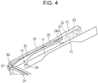
Fig. 4] Fig. 4 is an exploded, enlarged perspective view of a right temple of the glasses-shaped electronic device. - [
Fig. 5] Fig. 5 is an exploded, enlarged perspective view of part including a left modem of the glasses-shaped electronic device. - [
Fig. 6] Fig. 6 is an exploded, enlarged perspective view of part including a right modem of the glasses-shaped electronic device. - [
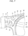
Fig. 7] Fig. 7 is an exploded, enlarged perspective view of part including a left hinge of the glasses-shaped electronic device. - [
Fig. 8] Fig. 8 is an exploded, enlarged perspective view of part including a right hinge of the glasses-shaped electronic device. - [
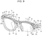
Fig. 9] Fig. 9 is an exploded, enlarged perspective view of the glasses-shaped electronic device and illustrates a mounted state of a flexible printed circuit in the glasses-shaped electronic device. - [
Fig. 10] Fig. 10 is an exploded, enlarged, rear perspective view illustrating a bridge of the glasses-shaped electronic device. - A glasses-shaped
electronic device 1 according to an embodiment of the present invention will be described below with reference to the drawings. - As illustrated in
Figs. 1 and2 , the glasses-shapedelectronic device 1 includes aneyeglass frame 2 made of plastic. - The
eyeglass frame 2 includes aleft temple 3 to be put on the left ear of a human and aright temple 4 to be put on the right ear of the human. Thesetemples eyeglass frame 2 including thetemples - The
eyeglass frame 2 further includes aleft rim 5 and aright rim 6 to whichlenses 60 are secured. Therims bridge 7. - A human
characteristic unit 50, which will be described later, for detecting an eye potential is mounted in thebridge 7 such that theunit 50 can be placed on the nose of a human. The present invention can also be applied to a device that eliminates the humancharacteristic detecting unit 50. - In addition, a
left hinge 8 is disposed between theleft temple 3 and theleft rim 5 and aright hinge 9 is disposed between theright temple 4 and theright rim 6. - The
temples rims hinges electronic device 1 is not used, typically, theleft temple 3 of theeyeglass frame 2 is moved inwardly and theright temple 4 is then moved inwardly so as to be superposed on theleft temple 3. - The
left temple 3 is integrally formed with a left slopingportion 10 and aleft temple tip 11, which serve as an end portion to be put on the left ear, such that the left slopingportion 10 is interposed between theleft temple 3 and theleft temple tip 11. Theright temple 4 is integrally formed with a right slopingportion 12 and aright temple tip 13, which serve as an end portion to be put on the right ear, such that the right slopingportion 12 is interposed between theright temple 4 and theright temple tip 13. - These
temple tips temple 3 and thetemple tip 11 and part connecting thetemple 4 and thetemple tip 13 are portions on which the weight of the glasses-shapedelectronic device 1 acts. - As illustrated in
Fig. 3 , theleft temple 3 and theleft temple tip 11 can be divided into two portions, or aninner half portion 14 and anouter half portion 15. Thehalf portions component compartment 16 extending through theleft temple 3 and theleft temple tip 11. - As illustrated in
Fig. 4 , theright temple 4 and theright temple tip 13 can also be divided into two portions, or aninner half portion 17 and anouter half portion 18. Thehalf portions component compartment 19 extending through theright temple 4 and theright temple tip 13. - The sloping
portions temple tips temples temple tips temples - The left electronic-
component compartment 16 accommodates arectangular battery 20 in theleft temple tip 11. Thebattery 20 is mounted in the whole of the storage space, located in theleft temple tip 11, in the left electronic-component compartment 16. The inside of theleft temple tip 11 serves as a dedicated mounting space for thebattery 20. Thus, a large capacity battery can be received. - The right electronic-
component compartment 19 accommodateselectric circuitry 21 in theright temple tip 13. Theelectric circuitry 21 includes a chargingcircuit 22 for thebattery 20. A power switch unit (not illustrated) is disposed in theright temple tip 13. - The
electric circuitry 21 includes electronic components, such as asensor unit 23 for detecting the posture of a human. Thesensor unit 23 includes an acceleration sensor and a gyroscopic sensor. The acceleration sensor is a sensor that detects acceleration acting on the glasses-shapedelectronic device 1. The acceleration sensor detects angular velocities in a plurality of axial directions (e.g., two or three axes) orthogonal to each other or one another. The gyroscopic senor is a sensor that detects rotations acting on the glasses-shapedelectronic device 1. The sensor unit in the present invention may include a six-axis gyroscopic sensor or a barometric pressure sensor. The sensor unit may include any kind of sensor. - The
sensor unit 23 detects a performance characteristic of a user, for example, the posture, motion, or vibration of the user. A signal indicating the performance characteristic detected by thesensor unit 23 is transmitted to a portable communication terminal, such as a smartphone, by wireless communication, such as Bluetooth (registered trademark) or a wireless local area network (LAN). - The human
characteristic detecting unit 50 is mounted in thebridge 7 of theeyeglass frame 2. The humancharacteristic detecting unit 50 detects the potential (e.g., eye potential) of the surface of the nose of a human. The detection can be used to obtain a variety of information, for example, information on fatigue of human eyes, based on the temperature of the skin. - The human
characteristic detecting unit 50 includes a leftnose electrode pad 51 that is to be located on a first side of the bridge of the nose of a human and is to contact the surface of the nose, a rod-shaped leftnose electrode member 52 having an end to which the leftnose electrode pad 51 is secured, a rightnose electrode pad 53 that is to be located on a second side of the bridge of the nose of the human and is to contact the surface of the nose, and a rod-shaped rightnose electrode member 54 having an end to which the rightnose electrode pad 53 is secured. - The human
characteristic detecting unit 50 further includes a plate-shapedglabella electrode pad 55 to contact the surface of part above the nose and between the eyebrows of a human and a rod-shapedglabella electrode member 56 having an end secured to central part of a rear surface of theglabella electrode pad 55. - The left
nose electrode member 51, the rightnose electrode member 53, and theglabella electrode member 55 are electrically connected to a printed wiring board 58 (refer toFig. 7 ) disposed in the humancharacteristic detecting unit 50. - The left
nose electrode member 52 detects the eye potential of the left eye, the rightnose electrode member 54 detects the eye potential of the right eye, and theglabella electrode member 56 detects an eye potential. The present invention can also be applied to a device that eliminates theglabella electrode member 56. - Examples of a material for the left
nose electrode member 52, the rightnose electrode member 54, and theglabella electrode member 56 include copper, titanium, and stainless steel. Thenose electrode members glabella electrode member 56 may be made of a conductive material. - For a material for the
nose electrode pads glabella electrode pad 55, each pad may be made of copper, titanium, or stainless steel. Each pad may be plated with, for example, copper or titanium. - The electronic-
component compartments FPC 24 establishes electrical connection between thebattery 20, theelectric circuitry 21, and the printed wiring board in the humancharacteristic detecting unit 50. - The use of the
FPC 24 as conductor wiring lines in the glasses-shapedelectronic device 1 facilitates wiring. In addition, since wiring lines of theFPC 24 are not exposed on the outside of the glasses-shapedelectronic device 1, the glasses-shaped electronic device with excellent design quality can be provided. - The left electronic-
component compartment 16 is defined between the two portions, or theinner half portion 14 and theouter half portion 15. The right electronic-component compartment 19 is also defined between the two portions, theinner half portion 17 and theouter half portion 18. To mount theFPC 24 in the electronic-component compartments outer half portions outer half portions FPC 24. - As illustrated in
Fig. 5 , the left electronic-component compartment 16 accommodates aleft connector 25 in the left slopingportion 10. Thebattery 20 is connected to aleft end 24A of the FPC by theleft connector 25. - A left
FPC positioning retainer 61 is disposed in the vicinity of theleft connector 25 in the left electronic-component compartment 16. The leftFPC positioning retainer 61 includes arib 61A disposed in theouter half portion 15 and aflange 61B attached to theleft end 24A of theFPC 24. - Engagement of the
flange 61B with therib 61A prevents theleft end 24A of theFPC 24 from detaching from theleft connector 25. Thus, stable connection between theFPC 24 and thebattery 20 can be maintained under tension on theFPC 24 when theFPC 24 is mounted in the left electronic-component compartment 16 or theleft temple 3 is moved inwardly. - The left electronic-
component compartment 16 further accommodates a leftwaterproof member 26 in the vicinity of theleft connector 25. The leftwaterproof member 26 prevents, for example, moisture and dust, from entering thebattery 20 and is made of, for example, PORON (registered trademark). - As illustrated in
Fig. 6 , the right electronic-component compartment 19 accommodates aright connector 27 in the right slopingportion 12. Theelectric circuitry 21 is connected to aright end 24B of the FPC by theright connector 27. - A right
FPC positioning retainer 62 is disposed in the vicinity of theright connector 27 in the right electronic-component compartment 19. The rightFPC positioning retainer 62 includes arib 62A disposed in theouter half portion 17 and aflange 62B attached to theright end 24B of theFPC 24. - Engagement of the
flange 62B with therib 62A prevents theright end 24B of theFPC 24 from detaching from theright connector 27. Thus, stable connection between theFPC 24 and theelectric circuitry 21 can be maintained under tension on theFPC 24 when theFPC 24 is mounted in the right electronic-component compartment 19 or theright temple 4 is moved inwardly. - The right electronic-
component compartment 19 further accommodates a rightwaterproof member 28 in the vicinity of theright connector 27. The rightwaterproof member 28 prevents, for example, moisture and dust, from entering theelectric circuitry 21 and is made of, for example, PORON (registered trademark). - In the present invention, the
FPC 24 may, instead of being a single piece, include a plurality of pieces coupled to each other or one another. The FPC has only to have a function of establishing electrical connection between thebattery 20, theelectric circuitry 21, and the printedwiring board 58 in the humancharacteristic detecting unit 50. - Upper part of the
left rim 5 of theeyeglass frame 2 can be divided into two portions, or aninner half portion 5A and anouter half portion 5B. AnFPC compartment 29 is defined between thehalf portions - In addition, the
left hinge 8 can also be divided into two portions, or aninner half portion 8A and anouter half portion 8B. As illustrated inFig. 7 , anFPC compartment 30 is defined between thehalf portions - Left part of the
FPC 24 is received such that the left part extends through theFPC compartment 29 in theleft rim 5, theFPC compartment 30 in theleft hinge 8, and the left electronic-component compartment 16. - Upper part of the
right rim 6 of theeyeglass frame 2 can also be divided into two portions, or aninner half portion 6A and anouter half portion 6B. AnFPC compartment 31 is defined between thehalf portions right hinge 9 can also be divided into two portions, or aninner half portion 9A and anouter half portion 9B. As illustrated inFig. 8 , anFPC compartment 32 is defined between thehalf portions - Right part of the
FPC 24 is received such that the right part extends through theFPC compartment 31 in theright rim 6, theFPC compartment 32 in theright hinge 9, and the right electronic-component compartment 19. - The
bridge 7 can also be divided into two portions, or aninner half portion 7A and anouter half portion 7B. As illustrated inFig. 9 , anFPC compartment 33 is defined between thehalf portions - The left part and the right part of the
FPC 24 join in theFPC compartment 33 in thebridge 7. - As illustrated in
Fig. 7 , theFPC compartment 29 in theleft rim 5 is slit-shaped. In theFPC compartment 29, theFPC 24 is held such that a main surface of theFPC 24 extends substantially horizontally. Thus, theFPC 24 can be received in a narrow portion of glasses, such as a rim thereof. - The
FPC 24 held in theFPC compartment 29 has a leftdeformable bend 24C. Part of theFPC 24 extending from the leftdeformable bend 24C to theleft hinge 8 is twisted by substantially 90° at an entrance to theleft hinge 8. TheFPC 24 extends around ahinge pin 8C in theFPC compartment 30 and is received in the left electronic-component compartment 16. TheFPC 24 is held in the left electronic-component compartment 16 such that the main surface of theFPC 24 extends substantially vertically. - A
left end piece 34 is located adjacent to theleft hinge 8. Theleft end piece 34 has aleft cavity 35 accommodating the leftdeformable bend 24C of theFPC 24. - Such a configuration prevents the
FPC 24 from experiencing tension when theleft temple 3 is moved inwardly, thus eliminating the possibility of a break in theFPC 24. The stable connection between theFPC 24 and thebattery 20 can be maintained. - A left
FPC positioning member 36 for preventing theFPC 24 from floating in theFPC compartment 29 is secured by apin 37 to theFPC compartment 29 in theleft rim 5 such that the leftFPC positioning member 36 is pressed against theouter half portion 5B of theleft rim 5. - The left
FPC positioning member 36 supports theFPC 24 in theFPC compartment 29 such that the main surface of theFPC 24 can extend substantially horizontally if theFPC 24 is twisted in theleft end piece 34, thus maintaining stable mounting of theFPC 24. - The left
FPC positioning member 36 has anFPC guide groove 38 having a function of guiding theFPC 24 in theFPC compartment 29. TheFPC 24 is movable in theFPC guide groove 38. - When the
FPC 24 is mounted in theleft rim 5, theFPC 24 can be temporarily fixed in theFPC compartment 29 by the leftFPC positioning member 36. Theleft rim 5 can be assembled without interference with theFPC 24. - The
pin 37 is exposed at a front surface of theleft rim 5. The exposedpin 37 serves as aleft marker 39 as a decorative member. - In the present embodiment, the
FPC 24 is twisted and mounted. In the present invention, theFPC 24 may be received in theleft rim 5 and theleft temple 3 such that theFPC 24 extends from theleft rim 5 to theleft temple 3 without being twisted. In addition, the position of theleft cavity 35 allowing deformation of theFPC 24 is not limited to theleft end piece 34. Theleft cavity 35 has only to be disposed adjacent to theleft hinge 8, provided that theleft cavity 35 has a function of allowing deformation of theFPC 24. - As illustrated in
Fig. 8 , theFPC compartment 31 in theright rim 6 is slit-shaped. In theFPC compartment 31, theFPC 24 is held such that the main surface of theFPC 24 extends substantially horizontally. Thus, theFPC 24 can be received in a narrow portion of glasses, such as a rim thereof. - The
FPC 24 held in theFPC compartment 31 has a rightdeformable bend 24D. Part of theFPC 24 extending from the leftdeformable bend 24D to theright hinge 9 is twisted by substantially 90° at an entrance to theright hinge 9. TheFPC 24 extends around ahinge pin 9C in theFPC compartment 30 and is received in the right electronic-component compartment 19. TheFPC 24 is held in the right electronic-component compartment 19 such that the main surface of theFPC 24 extends substantially vertically. - A
right end piece 40 is located adjacent to theright hinge 9. Theright end piece 40 has aright cavity 41 accommodating the rightdeformable bend 24D of theFPC 24. - Such a configuration prevents the
FPC 24 from experiencing tension when theright temple 4 is moved inwardly, thus eliminating the possibility of a break in theFPC 24. The stable connection between theFPC 24 and theelectric circuitry 21 can be maintained. - A right
FPC positioning member 42 for preventing theFPC 24 from floating in theFPC compartment 31 is secured by apin 43 to theFPC compartment 31 in theright rim 6 such that the rightFPC positioning member 42 is pressed against theouter half portion 6B of theright rim 6. - The right
FPC positioning member 42 supports theFPC 24 in theFPC compartment 31 such that the main surface of theFPC 24 can extend substantially horizontally if theFPC 24 is twisted in theright end piece 40, thus maintaining stable mounting of theFPC 24. - The right
FPC positioning member 42 has anFPC guide groove 43 having a function of guiding theFPC 24 in theFPC compartment 31. TheFPC 24 is movable in theFPC guide groove 43. - When the
FPC 24 is mounted in theright rim 6, theFPC 24 can be temporarily fixed in theFPC compartment 31 by the rightFPC positioning member 42. Theright rim 6 can be assembled without interference with theFPC 24. - The
pin 37 is exposed at a front surface of theright rim 6. The exposed pin serves as aleft marker 44 as a decorative member. - In the present embodiment, the
FPC 24 is twisted and mounted. In the present invention, theFPC 24 may be received in theright rim 6 and theright temple 4 such that theFPC 24 extends from theright rim 6 to theright temple 4 without being twisted. In addition, the position of theright cavity 41 accommodating the leftdeformable bend 24D of theFPC 24 is not limited to theright end piece 40. Theright cavity 41 has only to be disposed adjacent to theright hinge 9, provided that theright cavity 41 has a function of allowing deformation of theFPC 24. - As illustrated in
Fig. 10 , parts of theFPC 24 received in the FPC compartments 29 and 31 and located adjacent to thebridge 7 are twisted such that the main surface of theFPC 24 is turned by substantially 90°. TheFPC 24 is caught by a centralwaterproof member 59, which is included in the humancharacteristic detecting unit 50 and is made of PORON (registered trademark), for example. TheFPC 24 is attached to and pressed against an inner wall surface of theouter half portion 7B of thebridge 7 by acasing 57 of the humancharacteristic detecting unit 50 such that the main surface of theFPC 24 extends substantially vertically. Consequently, theFPC 24 is prevented from floating in thebridge 7, thus maintaining stable holding of theFPC 24. - The
FPC 24 in the humancharacteristic detecting unit 50 is electrically connected to the printedwiring board 58 such that a detection signal can be transmitted to theelectric circuitry 21. - The left and
right markers - The above-described glasses-shaped
electronic device 1 enables theFPC 24 to establish electrical connection between thebattery 20 disposed in theleft temple tip 11 and theelectric circuitry 21 disposed in theright temple tip 13. Such a configuration facilitates conductor wiring. In addition, this configuration eliminates the need for external arrangement of wiring lines. The glasses-shapedelectronic device 1 with ease of use can be provided. - Since the
FPC 24 can be received in thethin rims temples electronic device 1 with excellent design quality can be provided. - The arrangement of the
cavities FPC 24 in the vicinities of thehinges FPC 24 from experiencing unnecessary tension when thetemples FPC 24. - The
FPC positioning retainers FPC 24 from detaching from theconnectors FPC 24, thebattery 20, theelectric circuitry 21, and the humancharacteristic detecting unit 50 can be maintained. - The
left temple tip 11 accommodates thebattery 20 and theright temple tip 13 accommodates theelectric circuitry 21. This arrangement allows thebattery 20 to be separated from the chargingcircuit 22. In addition, the power switch unit is disposed adjacent to theelectric circuitry 21. Such arrangement allows a reduction in the number of electric wiring lines of theFPC 24 adjacent to thebattery 20, so that the electric wiring lines can be thickened. - The above-described embodiment is not intended to limit the present invention. It should be understood by those skilled in the art that various modifications, combinations, and alternations of the components of the above-described embodiment may be made within the technical scope of the present invention or the equivalents thereof.
- The glasses-shaped electronic device according to the present invention is also used as a device to be mounted on the head of a human to detect the posture of the human, and can be used to collect data in order to, for example, prevent a driver of a car from dozing or increase the running speed of an athlete.
-
- 1 glasses-shaped electronic device
- 2 eyeglass frame
- 3 left temple
- 4 right temple
- 5 left rim
- 6 right rim
- 7 bridge
- 8 left hinge
- 9 right hinge
- 11 left temple tip
- 13 right temple tip
- 16 left electronic-component compartment
- 19 right electronic-component compartment
- 20 battery
- 21 electric circuitry
- 24 flexible printed circuit (FPC)
- 24A left end
- 24B right end
- 24C left deformable bend
- 24D right deformable bend
- 25 left connector
- 27 right connector
- 29, 31, 33 FPC compartment
- 35 left cavity
- 36 left FPC positioning member
- 39 left marker
- 41 right cavity
- 42 right FPC positioning member
- 44 right marker
- 50 human characteristic detecting unit
- 61 left FPC positioning retainer
- 62 right FPC positioning retainer
Claims (7)
- A glasses-shaped electronic device comprising:an eyeglass frame including a bridge, rims, hinges, and temples; anda flexible printed circuit having deformable bends,the eyeglass frame having a flexible printed circuit compartment extending through the bridge, the rims, the hinges, and the temples, the compartment accommodating the flexible printed circuit,the eyeglass frame having cavities arranged adjacent to the compartment in the hinges, the cavities accommodating the deformable bends of the flexible printed circuit.
- The glasses-shaped electronic device according to Claim 1, wherein the flexible printed circuit compartment is defined between two portions into which each of the bridge, the rims, the hinges, and the temples is divided.
- The glasses-shaped electronic device according to Claim 1 or 2,
wherein the flexible printed circuit is held in the compartment in the rims such that a main surface of the flexible printed circuit extends substantially horizontally,
wherein parts of the flexible printed circuit extending from the deformable bends to the hinges are twisted by substantially 90° in the compartment adjacent to the hinges and the flexible printed circuit is held in the compartment in the temples such that the main surface extends substantially vertically, and
wherein parts of the flexible printed circuit adjacent to the bridge are twisted by substantially 90° in the compartment in the rims and the flexible printed circuit is held in the compartment in the bridge such that the main surface extends substantially vertically. - The glasses-shaped electronic device according to any one of Claims 1 to 3, further comprising:positioning members arranged in the compartment in the rims and mounted adjacent to the hinges, the positioning members supporting the flexible printed circuit such that the main surface is parallel to the rims.
- The glasses-shaped electronic device according to Claim 4, wherein each of the positioning members includes a marker exposed at a front surface of the corresponding one of the rims.
- The glasses-shaped electronic device according to any one of Claims 1 to 5, further comprising:a human characteristic detecting unit disposed in the bridge, the human characteristic detecting unit being configured to detect an eye potential while being in contact with a human nose,wherein the flexible printed circuit extends to right and left temple tips of the eyeglass frame such that the bridge of the eyeglass frame corresponds to middle part of the flexible printed circuit,wherein the flexible printed circuit is electrically connected to the human characteristic detecting unit in the bridge, andwherein the flexible printed circuit is electrically connected at a first end to a battery disposed in one of the temple tips by a connector and is electrically connected at a second end to electric circuitry disposed in the other one of the temple tips by a connector.
- The glasses-shaped electronic device according to Claim 6, further comprising:positioning retainers arranged in the compartment,wherein the first and second ends of the flexible printed circuit in the compartment in the temples are attached to the connectors by the positioning retainers.
Applications Claiming Priority (2)
| Application Number | Priority Date | Filing Date | Title |
|---|---|---|---|
| JP2015111664 | 2015-06-01 | ||
| PCT/JP2016/065827 WO2016194853A1 (en) | 2015-06-01 | 2016-05-27 | Glasses-type electronic device |
Publications (2)
| Publication Number | Publication Date |
|---|---|
| EP3306380A1 true EP3306380A1 (en) | 2018-04-11 |
| EP3306380A4 EP3306380A4 (en) | 2018-12-12 |
Family
ID=57441175
Family Applications (1)
| Application Number | Title | Priority Date | Filing Date |
|---|---|---|---|
| EP16803288.6A Withdrawn EP3306380A4 (en) | 2015-06-01 | 2016-05-27 | Glasses-type electronic device |
Country Status (4)
| Country | Link |
|---|---|
| US (1) | US10349861B2 (en) |
| EP (1) | EP3306380A4 (en) |
| JP (1) | JP6513195B2 (en) |
| WO (1) | WO2016194853A1 (en) |
Families Citing this family (33)
| Publication number | Priority date | Publication date | Assignee | Title |
|---|---|---|---|---|
| IT201600125574A1 (en) * | 2016-12-13 | 2018-06-13 | Safilo Sa Fabbrica Italiana Lavorazione Occhiali Spa | Glasses with bio-sensors |
| US10852562B2 (en) | 2017-10-31 | 2020-12-01 | Snap Inc. | Conductive connection through eyewear hinge |
| EP3710886B1 (en) | 2017-11-16 | 2023-05-10 | Safilo Società Azionaria Fabbrica Italiana Lavorazione Occhiali S.p.A. | Pair of spectacles with bio-sensors |
| JP6691928B2 (en) * | 2018-02-07 | 2020-05-13 | 株式会社ジンズホールディングス | Eyewear set and signal processing unit |
| JP1623458S (en) * | 2018-07-31 | 2020-01-27 | ||
| US10353221B1 (en) * | 2018-07-31 | 2019-07-16 | Bose Corporation | Audio eyeglasses with cable-through hinge and related flexible printed circuit |
| JP1623460S (en) * | 2018-07-31 | 2020-01-27 | ||
| USD908787S1 (en) * | 2019-01-30 | 2021-01-26 | Jins Holdings Inc. | Eyeglasses |
| NL2022592B1 (en) * | 2019-02-15 | 2020-08-28 | Morrow N V | Method of integrating an electronic device into an eyeglass frame, and electronic glasses |
| WO2020171768A1 (en) * | 2019-02-22 | 2020-08-27 | Skugga Technology Ab | Single unit comprising electronics for smart glasses |
| USD1019747S1 (en) * | 2019-09-09 | 2024-03-26 | Amazon Technologies, Inc. | Wearable device |
| CN110955064A (en) * | 2019-12-30 | 2020-04-03 | 邯郸市富亚电子技术有限公司 | Self-sensing switch-type smart color-changing sunglasses |
| US11513366B2 (en) * | 2020-01-31 | 2022-11-29 | Bose Corporation | Audio eyeglasses with double-detent hinge |
| US11662609B2 (en) | 2020-01-31 | 2023-05-30 | Bose Corporation | Wearable audio device with cable-through hinge |
| JP6957695B1 (en) * | 2020-07-30 | 2021-11-02 | 株式会社ジンズホールディングス | Programs, information processing methods, and information processing equipment |
| DE102020210683B3 (en) | 2020-08-21 | 2021-11-25 | Obe Gmbh & Co. Kg | Central part for a glasses hinge and glasses with such a central part |
| US20230301574A1 (en) * | 2020-08-27 | 2023-09-28 | Shimadzu Corporation | Wearable Device and Detection System |
| CN222838307U (en) * | 2024-07-22 | 2025-05-06 | 所乐思(深圳)科技有限公司 | Hinge connecting wire with sensing function and intelligent glasses |
| USD1020856S1 (en) * | 2023-02-09 | 2024-04-02 | Innovative Eyewear, Inc. | Smartglasses |
| USD1020863S1 (en) * | 2023-02-09 | 2024-04-02 | Innovative Eyewear, Inc. | Smartglasses |
| USD1020849S1 (en) * | 2023-02-09 | 2024-04-02 | Innovative Eyewear, Inc. | Smartglasses |
| USD1020858S1 (en) * | 2023-02-09 | 2024-04-02 | Innovative Eyewear, Inc. | Smartglasses |
| USD1020850S1 (en) * | 2023-02-09 | 2024-04-02 | Innovative Eyewear, Inc. | Smartglasses |
| USD1019746S1 (en) * | 2023-02-09 | 2024-03-26 | Innovative Eyewear, Inc. | Smartglasses |
| USD1024177S1 (en) * | 2023-02-09 | 2024-04-23 | Innovative Eyewear, Inc. | Smartglasses |
| USD1020853S1 (en) * | 2023-02-09 | 2024-04-02 | Innovative Eyewear, Inc. | Smartglasses |
| USD1020854S1 (en) * | 2023-02-09 | 2024-04-02 | Innovative Eyewear, Inc. | Smartglasses |
| USD1020852S1 (en) * | 2023-02-09 | 2024-04-02 | Innovative Eyewear, Inc | Smartglasses |
| USD1019750S1 (en) * | 2023-02-09 | 2024-03-26 | Innovative Eyewear, Inc. | Smartglasses |
| USD1020851S1 (en) * | 2023-02-09 | 2024-04-02 | Innovative Eyewear, Inc. | Smartglasses |
| USD1020857S1 (en) * | 2023-02-09 | 2024-04-02 | Innovative Eyewear, Inc. | Smartglasses |
| USD1020855S1 (en) * | 2023-02-09 | 2024-04-02 | Innovative Eyewear, Inc. | Smartglasses |
| USD1023123S1 (en) * | 2023-02-13 | 2024-04-16 | Innovative Eyewear, Inc. | Smartglasses temples |
Family Cites Families (17)
| Publication number | Priority date | Publication date | Assignee | Title |
|---|---|---|---|---|
| US3119903A (en) * | 1955-12-08 | 1964-01-28 | Otarion Inc | Combination eyeglass frame and hearing aid unit |
| US3095483A (en) * | 1956-03-23 | 1963-06-25 | Paravox Inc | Hearing aid device |
| US2916538A (en) * | 1958-09-08 | 1959-12-08 | Maico Electronics Inc | Temple-mounted hearing aid control |
| US2904639A (en) * | 1958-09-22 | 1959-09-15 | Maico Electronics Inc | Temple construction |
| JPH04151620A (en) * | 1990-10-16 | 1992-05-25 | Seiko Epson Corp | Eyeglass frames with UV amount display |
| CA2059597A1 (en) * | 1991-01-22 | 1992-07-23 | Paul A. Vogt | Radio eyewear |
| US5835185A (en) * | 1993-09-10 | 1998-11-10 | Kallman; William R. | Spring-hinged frame for eyeware |
| US6769767B2 (en) * | 2001-04-30 | 2004-08-03 | Qr Spex, Inc. | Eyewear with exchangeable temples housing a transceiver forming ad hoc networks with other devices |
| US20070200998A1 (en) * | 2006-02-24 | 2007-08-30 | Chemical Light, Inc. | Led illuminated novelty glasses |
| TW200804887A (en) * | 2006-07-12 | 2008-01-16 | Jia-Lin Jou | Slim frame of spectacle having electronic device thereon, and spectacle having the same |
| US8801174B2 (en) * | 2011-02-11 | 2014-08-12 | Hpo Assets Llc | Electronic frames comprising electrical conductors |
| JP5699649B2 (en) * | 2011-02-04 | 2015-04-15 | セイコーエプソン株式会社 | Virtual image display device |
| ITGE20120054A1 (en) * | 2012-05-21 | 2013-11-22 | Michele Iurilli | EYEWEAR INCLUDING ELECTRICAL AND / OR ELECTRONIC ELEMENTS |
| JP5661067B2 (en) * | 2012-05-29 | 2015-01-28 | 株式会社ジェイアイエヌ | Eyewear |
| US9442305B2 (en) * | 2012-06-14 | 2016-09-13 | Mitsui Chemicals, Inc. | Electronic eyeglasses and methods of manufacturing |
| FR2996014B1 (en) * | 2012-09-26 | 2015-12-25 | Interactif Visuel Systeme I V S | METHOD FOR AIDING THE DETERMINATION OF VISION PARAMETERS OF A SUBJECT |
| US20160026009A1 (en) * | 2012-11-01 | 2016-01-28 | Nejc Urbajs | Glasses for amblyopia treatment |
-
2016
- 2016-05-27 JP JP2017521928A patent/JP6513195B2/en not_active Expired - Fee Related
- 2016-05-27 WO PCT/JP2016/065827 patent/WO2016194853A1/en not_active Ceased
- 2016-05-27 EP EP16803288.6A patent/EP3306380A4/en not_active Withdrawn
-
2017
- 2017-11-01 US US15/801,211 patent/US10349861B2/en active Active
Also Published As
| Publication number | Publication date |
|---|---|
| WO2016194853A1 (en) | 2016-12-08 |
| JPWO2016194853A1 (en) | 2018-04-12 |
| US20180049664A1 (en) | 2018-02-22 |
| US10349861B2 (en) | 2019-07-16 |
| JP6513195B2 (en) | 2019-05-15 |
| EP3306380A4 (en) | 2018-12-12 |
Similar Documents
| Publication | Publication Date | Title |
|---|---|---|
| US10349861B2 (en) | Glasses-shaped electronic device | |
| US10357152B2 (en) | Glasses-shaped electronic device | |
| KR102770764B1 (en) | Wearable electronic device and method for detecting contact of living body in wearable electronic device | |
| JP7015378B2 (en) | Eyewear | |
| JP5319803B2 (en) | Head-mounted display device, eyeglass display device, and eyeglass modern for display device | |
| KR102780302B1 (en) | Electronic device for measuring bio-signals | |
| WO2016194848A1 (en) | Human body characteristic detecting device and spectacle-type electronic equipment | |
| US20170255029A1 (en) | Systems and methods for charging eyewear | |
| CN111248901B (en) | Nose pad and eye wear tool | |
| CN110115560B (en) | Eyewear kit and signal processing unit | |
| JP6937756B2 (en) | Glasses with biological signal sensor | |
| US20130324826A1 (en) | Biological signal measurement apparatus, biological signal measurement equipment, and biological signal measurement apparatus set | |
| CN114222941B (en) | Eyewear straps | |
| JP6975097B2 (en) | Eyewear system | |
| CN106455970A (en) | Eyewear | |
| JP2005211388A (en) | Connection unit for biological information measuring apparatus | |
| CN110268302B (en) | Glasses including biosensors | |
| EP3555697B1 (en) | Glasses comprising biosensors | |
| US12307014B2 (en) | Earbud sensory assembly | |
| US12332505B1 (en) | Eyewear tether with battery | |
| KR102253550B1 (en) | Wearable device including a leakage current protection structure | |
| WO2015159858A1 (en) | Eyewear | |
| JPWO2015170662A1 (en) | Human body characteristic detection apparatus and glasses-type electronic device |
Legal Events
| Date | Code | Title | Description |
|---|---|---|---|
| PUAI | Public reference made under article 153(3) epc to a published international application that has entered the european phase |
Free format text: ORIGINAL CODE: 0009012 |
|
| 17P | Request for examination filed |
Effective date: 20171130 |
|
| AK | Designated contracting states |
Kind code of ref document: A1 Designated state(s): AL AT BE BG CH CY CZ DE DK EE ES FI FR GB GR HR HU IE IS IT LI LT LU LV MC MK MT NL NO PL PT RO RS SE SI SK SM TR |
|
| AX | Request for extension of the european patent |
Extension state: BA ME |
|
| DAV | Request for validation of the european patent (deleted) | ||
| DAX | Request for extension of the european patent (deleted) | ||
| A4 | Supplementary search report drawn up and despatched |
Effective date: 20181108 |
|
| RIC1 | Information provided on ipc code assigned before grant |
Ipc: G02C 5/02 20060101ALI20181102BHEP Ipc: A61B 3/10 20060101ALI20181102BHEP Ipc: G02C 11/00 20060101AFI20181102BHEP Ipc: A61B 5/0408 20060101ALI20181102BHEP Ipc: A61B 5/0496 20060101ALI20181102BHEP Ipc: G02C 5/22 20060101ALI20181102BHEP Ipc: A61B 5/0478 20060101ALI20181102BHEP Ipc: G02C 5/14 20060101ALI20181102BHEP |
|
| RAP1 | Party data changed (applicant data changed or rights of an application transferred) |
Owner name: ALPS ALPINE CO., LTD. |
|
| STAA | Information on the status of an ep patent application or granted ep patent |
Free format text: STATUS: THE APPLICATION HAS BEEN WITHDRAWN |
|
| 18W | Application withdrawn |
Effective date: 20200806 |