EP3306337A1 - User equipment localization in a mobile communication network - Google Patents
User equipment localization in a mobile communication network Download PDFInfo
- Publication number
- EP3306337A1 EP3306337A1 EP16193154.8A EP16193154A EP3306337A1 EP 3306337 A1 EP3306337 A1 EP 3306337A1 EP 16193154 A EP16193154 A EP 16193154A EP 3306337 A1 EP3306337 A1 EP 3306337A1
- Authority
- EP
- European Patent Office
- Prior art keywords
- enb
- receiver
- transmitter
- prs
- prs sequence
- Prior art date
- Legal status (The legal status is an assumption and is not a legal conclusion. Google has not performed a legal analysis and makes no representation as to the accuracy of the status listed.)
- Withdrawn
Links
Images




Classifications
-
- G—PHYSICS
- G01—MEASURING; TESTING
- G01S—RADIO DIRECTION-FINDING; RADIO NAVIGATION; DETERMINING DISTANCE OR VELOCITY BY USE OF RADIO WAVES; LOCATING OR PRESENCE-DETECTING BY USE OF THE REFLECTION OR RERADIATION OF RADIO WAVES; ANALOGOUS ARRANGEMENTS USING OTHER WAVES
- G01S1/00—Beacons or beacon systems transmitting signals having a characteristic or characteristics capable of being detected by non-directional receivers and defining directions, positions, or position lines fixed relatively to the beacon transmitters; Receivers co-operating therewith
- G01S1/02—Beacons or beacon systems transmitting signals having a characteristic or characteristics capable of being detected by non-directional receivers and defining directions, positions, or position lines fixed relatively to the beacon transmitters; Receivers co-operating therewith using radio waves
- G01S1/04—Details
- G01S1/042—Transmitters
- G01S1/0428—Signal details
-
- G—PHYSICS
- G01—MEASURING; TESTING
- G01S—RADIO DIRECTION-FINDING; RADIO NAVIGATION; DETERMINING DISTANCE OR VELOCITY BY USE OF RADIO WAVES; LOCATING OR PRESENCE-DETECTING BY USE OF THE REFLECTION OR RERADIATION OF RADIO WAVES; ANALOGOUS ARRANGEMENTS USING OTHER WAVES
- G01S1/00—Beacons or beacon systems transmitting signals having a characteristic or characteristics capable of being detected by non-directional receivers and defining directions, positions, or position lines fixed relatively to the beacon transmitters; Receivers co-operating therewith
- G01S1/02—Beacons or beacon systems transmitting signals having a characteristic or characteristics capable of being detected by non-directional receivers and defining directions, positions, or position lines fixed relatively to the beacon transmitters; Receivers co-operating therewith using radio waves
- G01S1/08—Systems for determining direction or position line
- G01S1/20—Systems for determining direction or position line using a comparison of transit time of synchronised signals transmitted from non-directional antennas or antenna systems spaced apart, i.e. path-difference systems
-
- G—PHYSICS
- G01—MEASURING; TESTING
- G01S—RADIO DIRECTION-FINDING; RADIO NAVIGATION; DETERMINING DISTANCE OR VELOCITY BY USE OF RADIO WAVES; LOCATING OR PRESENCE-DETECTING BY USE OF THE REFLECTION OR RERADIATION OF RADIO WAVES; ANALOGOUS ARRANGEMENTS USING OTHER WAVES
- G01S11/00—Systems for determining distance or velocity not using reflection or reradiation
- G01S11/02—Systems for determining distance or velocity not using reflection or reradiation using radio waves
- G01S11/06—Systems for determining distance or velocity not using reflection or reradiation using radio waves using intensity measurements
-
- G—PHYSICS
- G01—MEASURING; TESTING
- G01S—RADIO DIRECTION-FINDING; RADIO NAVIGATION; DETERMINING DISTANCE OR VELOCITY BY USE OF RADIO WAVES; LOCATING OR PRESENCE-DETECTING BY USE OF THE REFLECTION OR RERADIATION OF RADIO WAVES; ANALOGOUS ARRANGEMENTS USING OTHER WAVES
- G01S5/00—Position-fixing by co-ordinating two or more direction or position line determinations; Position-fixing by co-ordinating two or more distance determinations
- G01S5/02—Position-fixing by co-ordinating two or more direction or position line determinations; Position-fixing by co-ordinating two or more distance determinations using radio waves
- G01S5/0205—Details
- G01S5/0226—Transmitters
-
- G—PHYSICS
- G01—MEASURING; TESTING
- G01S—RADIO DIRECTION-FINDING; RADIO NAVIGATION; DETERMINING DISTANCE OR VELOCITY BY USE OF RADIO WAVES; LOCATING OR PRESENCE-DETECTING BY USE OF THE REFLECTION OR RERADIATION OF RADIO WAVES; ANALOGOUS ARRANGEMENTS USING OTHER WAVES
- G01S5/00—Position-fixing by co-ordinating two or more direction or position line determinations; Position-fixing by co-ordinating two or more distance determinations
- G01S5/02—Position-fixing by co-ordinating two or more direction or position line determinations; Position-fixing by co-ordinating two or more distance determinations using radio waves
- G01S5/0257—Hybrid positioning
- G01S5/0258—Hybrid positioning by combining or switching between measurements derived from different systems
- G01S5/02585—Hybrid positioning by combining or switching between measurements derived from different systems at least one of the measurements being a non-radio measurement
-
- G—PHYSICS
- G01—MEASURING; TESTING
- G01S—RADIO DIRECTION-FINDING; RADIO NAVIGATION; DETERMINING DISTANCE OR VELOCITY BY USE OF RADIO WAVES; LOCATING OR PRESENCE-DETECTING BY USE OF THE REFLECTION OR RERADIATION OF RADIO WAVES; ANALOGOUS ARRANGEMENTS USING OTHER WAVES
- G01S5/00—Position-fixing by co-ordinating two or more direction or position line determinations; Position-fixing by co-ordinating two or more distance determinations
- G01S5/02—Position-fixing by co-ordinating two or more direction or position line determinations; Position-fixing by co-ordinating two or more distance determinations using radio waves
- G01S5/0273—Position-fixing by co-ordinating two or more direction or position line determinations; Position-fixing by co-ordinating two or more distance determinations using radio waves using multipath or indirect path propagation signals in position determination
-
- G—PHYSICS
- G01—MEASURING; TESTING
- G01S—RADIO DIRECTION-FINDING; RADIO NAVIGATION; DETERMINING DISTANCE OR VELOCITY BY USE OF RADIO WAVES; LOCATING OR PRESENCE-DETECTING BY USE OF THE REFLECTION OR RERADIATION OF RADIO WAVES; ANALOGOUS ARRANGEMENTS USING OTHER WAVES
- G01S5/00—Position-fixing by co-ordinating two or more direction or position line determinations; Position-fixing by co-ordinating two or more distance determinations
- G01S5/02—Position-fixing by co-ordinating two or more direction or position line determinations; Position-fixing by co-ordinating two or more distance determinations using radio waves
- G01S5/0284—Relative positioning
-
- G—PHYSICS
- G01—MEASURING; TESTING
- G01S—RADIO DIRECTION-FINDING; RADIO NAVIGATION; DETERMINING DISTANCE OR VELOCITY BY USE OF RADIO WAVES; LOCATING OR PRESENCE-DETECTING BY USE OF THE REFLECTION OR RERADIATION OF RADIO WAVES; ANALOGOUS ARRANGEMENTS USING OTHER WAVES
- G01S5/00—Position-fixing by co-ordinating two or more direction or position line determinations; Position-fixing by co-ordinating two or more distance determinations
- G01S5/02—Position-fixing by co-ordinating two or more direction or position line determinations; Position-fixing by co-ordinating two or more distance determinations using radio waves
- G01S5/08—Position of single direction-finder fixed by determining direction of a plurality of spaced sources of known location
-
- G—PHYSICS
- G01—MEASURING; TESTING
- G01S—RADIO DIRECTION-FINDING; RADIO NAVIGATION; DETERMINING DISTANCE OR VELOCITY BY USE OF RADIO WAVES; LOCATING OR PRESENCE-DETECTING BY USE OF THE REFLECTION OR RERADIATION OF RADIO WAVES; ANALOGOUS ARRANGEMENTS USING OTHER WAVES
- G01S5/00—Position-fixing by co-ordinating two or more direction or position line determinations; Position-fixing by co-ordinating two or more distance determinations
- G01S5/02—Position-fixing by co-ordinating two or more direction or position line determinations; Position-fixing by co-ordinating two or more distance determinations using radio waves
- G01S5/12—Position-fixing by co-ordinating two or more direction or position line determinations; Position-fixing by co-ordinating two or more distance determinations using radio waves by co-ordinating position lines of different shape, e.g. hyperbolic, circular, elliptical or radial
-
- G—PHYSICS
- G01—MEASURING; TESTING
- G01S—RADIO DIRECTION-FINDING; RADIO NAVIGATION; DETERMINING DISTANCE OR VELOCITY BY USE OF RADIO WAVES; LOCATING OR PRESENCE-DETECTING BY USE OF THE REFLECTION OR RERADIATION OF RADIO WAVES; ANALOGOUS ARRANGEMENTS USING OTHER WAVES
- G01S5/00—Position-fixing by co-ordinating two or more direction or position line determinations; Position-fixing by co-ordinating two or more distance determinations
- G01S5/02—Position-fixing by co-ordinating two or more direction or position line determinations; Position-fixing by co-ordinating two or more distance determinations using radio waves
- G01S5/14—Determining absolute distances from a plurality of spaced points of known location
-
- H—ELECTRICITY
- H04—ELECTRIC COMMUNICATION TECHNIQUE
- H04L—TRANSMISSION OF DIGITAL INFORMATION, e.g. TELEGRAPHIC COMMUNICATION
- H04L47/00—Traffic control in data switching networks
- H04L47/10—Flow control; Congestion control
- H04L47/34—Flow control; Congestion control ensuring sequence integrity, e.g. using sequence numbers
-
- H—ELECTRICITY
- H04—ELECTRIC COMMUNICATION TECHNIQUE
- H04L—TRANSMISSION OF DIGITAL INFORMATION, e.g. TELEGRAPHIC COMMUNICATION
- H04L5/00—Arrangements affording multiple use of the transmission path
- H04L5/003—Arrangements for allocating sub-channels of the transmission path
- H04L5/0048—Allocation of pilot signals, i.e. of signals known to the receiver
-
- H—ELECTRICITY
- H04—ELECTRIC COMMUNICATION TECHNIQUE
- H04W—WIRELESS COMMUNICATION NETWORKS
- H04W4/00—Services specially adapted for wireless communication networks; Facilities therefor
- H04W4/02—Services making use of location information
- H04W4/029—Location-based management or tracking services
-
- H—ELECTRICITY
- H04—ELECTRIC COMMUNICATION TECHNIQUE
- H04W—WIRELESS COMMUNICATION NETWORKS
- H04W48/00—Access restriction; Network selection; Access point selection
- H04W48/08—Access restriction or access information delivery, e.g. discovery data delivery
- H04W48/10—Access restriction or access information delivery, e.g. discovery data delivery using broadcasted information
-
- H—ELECTRICITY
- H04—ELECTRIC COMMUNICATION TECHNIQUE
- H04W—WIRELESS COMMUNICATION NETWORKS
- H04W64/00—Locating users or terminals or network equipment for network management purposes, e.g. mobility management
- H04W64/003—Locating users or terminals or network equipment for network management purposes, e.g. mobility management locating network equipment
-
- G—PHYSICS
- G01—MEASURING; TESTING
- G01S—RADIO DIRECTION-FINDING; RADIO NAVIGATION; DETERMINING DISTANCE OR VELOCITY BY USE OF RADIO WAVES; LOCATING OR PRESENCE-DETECTING BY USE OF THE REFLECTION OR RERADIATION OF RADIO WAVES; ANALOGOUS ARRANGEMENTS USING OTHER WAVES
- G01S5/00—Position-fixing by co-ordinating two or more direction or position line determinations; Position-fixing by co-ordinating two or more distance determinations
- G01S5/02—Position-fixing by co-ordinating two or more direction or position line determinations; Position-fixing by co-ordinating two or more distance determinations using radio waves
- G01S5/0205—Details
- G01S5/0218—Multipath in signal reception
Definitions
- the present invention concerns the field of wireless communication networks or systems, more specifically the localization of user equipment, like mobile terminals, in such a network.
- Fig. 1 is a schematic representation of an example of a network infrastructure, such as a wireless communication network or wireless communication system, including a plurality of base stations eNB 1 to eNB 5 , each serving a specific area surrounding the base station schematically represented by the respective cells 100 1 to 100 5 .
- the base stations are provided to serve users within a cell.
- a user may be a stationary device or a mobile device.
- the wireless communication system may be accessed by loT devices which connect to a base station or to a user.
- loT devices may include physical devices, vehicles, buildings and other items having embedded therein electronics, software, sensors, actuators, or the like as well as network connectivity that enable these devices to collect and exchange data across an existing network infrastructure.
- loT devices may include physical devices, vehicles, buildings and other items having embedded therein electronics, software, sensors, actuators, or the like as well as network connectivity that enable these devices to collect and exchange data across an existing network infrastructure.
- Fig. 1 shows an exemplary view of only five cells, however, the wireless communication system may include more such cells.
- Fig. 1 shows two users UE1 and UE2, also referred to as user equipment (UE), that are in cell 100 2 and that are served by base station eNB 2 .
- Another user UE 3 is shown in cell 100 4 which is served by base station eNB 4 .
- the arrows 102 1 , 102 2 and 102 3 schematically represent uplink/downlink connections for transmitting data from a user UE 1 , UE 2 and UE 3 to the base stations eNB 2 , eNB 4 or for transmitting data from the base stations eNB 2 , eNB 4 to the users UE 1 , UE 2 , UE 3 .
- Fig. 1 shows two users UE1 and UE2, also referred to as user equipment (UE), that are in cell 100 2 and that are served by base station eNB 2 .
- Another user UE 3 is shown in cell 100 4 which is
- loT device 104 1 shows two loT devices 104 1 and 104 2 in cell 100 4 , which may be stationary or mobile devices.
- the loT device 104 1 accesses the wireless communication system via the base station eNB 4 to receive and transmit data as schematically represented by arrow 106 1 .
- the IoT device 104 2 accesses the wireless communication system via the user UE 3 as is schematically represented by arrow 106 2 .
- the wireless communication system may be any single-tone or multicarrier system based on frequency-division multiplexing, like the orthogonal frequency-division multiplexing (OFDM) system, the orthogonal frequency-division multiple access (OFDMA) system defined by the LTE standard, or any other IFFT-based signal with or without CP, e.g. DFT-s-OFDM.
- OFDM orthogonal frequency-division multiplexing
- OFDMA orthogonal frequency-division multiple access
- Other waveforms like non-orthogonal waveforms for multiple access, e.g. filter-bank multicarrier (FBMC), may be used.
- FBMC filter-bank multicarrier
- a wireless communication network like the one depicted in Fig. 1 , it may be desired to locate a UE with a certain accuracy in a cell.
- One approach to locate a UE within a cell is based on an observed time difference of arrival (OTDOA) estimation that may be used in cellular communication networks, such as LTE, and which is a downlink positioning method that relies on the calculation of time of arrival (TOA) estimates using position reference signals (PRS) receives at the user equipment UE from one or more surrounding base stations (eNB), as is described, for example, in references [2] and [3].
- PRS sequences are downlink signals that are designed for positioning purposes and that are broadcast to all radio terminals within a cell.
- the PRS sequences are radiated with the same transmit power from the antenna of the base station or the remote radio head (RRH) in all directions to cover all users at any location of the cell, i.e., to provide a cell-wide coverage.
- each PRS sequence has associated therewith a cell-specific identifier also referred to as a physical cell identifier (PCI).
- PCI is unique in a specific area and is used to identify the cell and thus the PRS sequence.
- At least three timing measurements from geometrically dispersed base stations are required, relative to the UE's internal time base, in order to obtain a unique position in a plane. Four base stations are needed to obtain a unique position in a three-dimensional space as is described in reference [4].
- Fig. 2 is a schematic representation of a OTDOA measurement using three base stations, wherein the figure is based on an image taken from reference [4].
- the base stations eNB 1 to eNB 3 send out respective PRS sequences having associated therewith a PCI.
- Base station eNB 1 sends out the PRS sequence PRS 1
- base station eNB 2 sends out the PRS sequence PRS 2
- base station eNB 3 sends out the PRS sequence PRS 3 .
- the base stations eNB 1 to eNB 3 serve different cells of the wireless communication network.
- each base station transmits the sequences in all directions to cover all users at any location within the respective cell.
- a user equipment is assumed to be at location 108.
- the UE at location 108 receives from the respective base stations the PRS sequences PRS1 to PRS3.
- the UE at location 108 measures three TOAs ⁇ 1 , ⁇ 2 , ⁇ 3 relative to the UE internal time base.
- the relative signal timing differences are fed back to the base station serving the user equipment at location 108, as well as to a location server.
- the location server may be part of the base station or it may be an element separate from the base station, as is indicated at 110 in Fig. 1 .
- the location server 110 may be part of the overall network structure and may be connected to each of the base stations shown in Fig. 1 , although only one connection is shown in dotted lines in Fig. 1 .
- the RSTD values are related to the geometric distances between the UE and the base stations and define hyperbolas around the respective locations of the base stations, as is indicated by line ⁇ 3 - ⁇ 1 and line ⁇ 2 - ⁇ 1 in Fig. 2 .
- the location server may determine the position of the UE.
- the hyperbolas are shown with a width illustrating the measurement uncertainty.
- the estimated UE location is the intersection area of the two hyperbolas.
- the first arriving signal path from each base station is to be accurately estimated.
- the TOA estimates reflect the first detected LoS peaks in a cross-correlation of the received signal with a PRS sequence, which is known at the UE, so that the TOA directly corresponds to the distances between the UE and the base station. This allows accurate position estimates for the UE.
- the TOA estimates, and therefore also the RSTD measurements may be biased by an obstruction of the LoS path or by the non-line-of-side (NLoS) signal path components of the channel and, in such a situation, the UE may not correctly detect the first arriving signal path which may lead to erroneous distance information.
- NNLoS non-line-of-side
- the above described approach for localizing a UE within the cell uses PRS sequences that are transmitted by a plurality of base stations. Each base station sends out the same PRS sequence in all directions to cover all users. To allow for a localization at least three base stations are needed. Further, the radio propagation channel may suffer from a multipath propagation and shadowing or fading conditions so that the RSTD measurements may not be accurate. Multipath is a phenomenon that happens in the channel of mobile systems when the transmitted signal arrives at the receiver via different paths due to reflection, diffraction and scattering resulting in fading. This is schematically represented in Fig.
- the PRS sequence PRS i may not be directly received at the UE due to an obstacle 112 1 scattering or shadowing the signal so that there is a path loss behind the obstacle 112 1 .
- the UE may receive the sequence PRS i due to a reflection of the signal at the obstacle 112 2 and/or due to a diffraction at the obstacle 112 3 .
- the obstacles 112 1 to 112 3 like buildings, hills and trees, in the signal paths cause the signal to arrive at the UE from various directions with different delays.
- the multipath may be a source of error in the TOA estimation, for example, when there is no line of side path, even if the receiver UE detects the first arriving path.
- NLoS error mitigation techniques may assume that the NLoS corrupted TOA measurements are only a small portion of the total number of measurements, i.e., some of the links between the UE and the base station contain an LoS channel path.
- Another approach may detect NLoS corrupted TOA measurements due to their inconsistency with the expected measurement for a LoS scenario so that NLoS links between the UE and the base station may be identified and ignored for the localizing of the UE position as is, for example, described in references [8] and [12].
- Yet other approaches may use all links between the UE and the base station and may introduce a weighting or scaling of TOA measurements to minimize the NLoS contributions, as is described in reference [13], or detect the NLoS errors and use the information to calculate all possible UE locations, as is described in reference [14].
- the base stations of the wireless communication network include a plurality of antennas ANT, for example formed by an antenna array including a plurality of antenna elements, and the UE may also include more than one antenna.
- location-independent parameters may be exploited in addition to the OTDOA measurements of the LoS or NLoS path components, for example an angle of arrival (AoA) at the UE and an angle of departure (AoD) at the base station may be used.
- AoA angle of arrival
- AoD angle of departure
- examples of localization techniques may benefit from the NLoS channel propagation by exploiting the geometrical relationship of possible UE locations implied by the NLoS path components.
- Such techniques are described, for example, in references [15] and [16] and rely on a parametric description of the multipath channel propagation environment, assuming knowledge of the path-dependent parameters AoD, AoA and the path distance d.
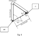
- Fig. 4 is a geometrical description of a single path component (single bounce reflection) for LoS and NLoS propagation of a PRS containing signal transmitted from the base station eNB towards a user equipment UE.
- Fig. 4 indicates the LoS path component, the NLoS path component, the angle of departure (AoD) of the signal at the base station, and the angle of arrival (AoD) at the UE.
- the parameters AoD, AoA and d may be estimated either at the UE and/or at the base station from the downlink/uplink reference signals.
- the AoA(s) of the path components are typically estimated at the base station by evaluating uplink sounding reference signals such as SRS sent by the UE.
- the AoA(s) may be estimated using the MUSIC algorithm or the SAGE algorithm. Assuming a system operating in a time-division-duplex (TDD) mode, and assuming that the forward and reverse channels are symmetric, the UE may estimate the AoA of each path component, which corresponds to the AoD of the reverse link by evaluating downlink sounding reference symbols, such as CSI-RS and/or PRS sent out by the base station. The distance d of each LoS/NLoS propagation path may be obtained from the respective TOA estimate at the UE.
- TDD time-division-duplex
- the TOA(s) and AoA(s) of a path component may be jointly estimated and the estimated AoA(s) and TOA(s) are fed back to the serving base station and/or to a location server, the latter using the estimated path parameters AoD, AoA and d together with a geometrical channel model description to perform the UE localization.
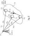
- Fig. 5 shows an example of a cell of a wireless communication network operating, for localizing a user equipment UE, in accordance with the inventive approach described herein.
- the wireless communication network includes the cell i which is served by the base station BS.
- the base station BS includes a large-scale array antenna 114, also referred to as a massive array antenna.
- the array antenna may include a plurality of antenna elements. At least two antenna elements are provided to allow for beamforming of the signals to be transmitted by the antenna 114 to allow for a directional signal transmission of the signals.
- the number of antennas or antenna elements may be higher than 2, for example the array may include 32, 64 or more antenna elements.
- the base station BS forms a plurality of beam cones or lobes 116 1 to 116 3 .
- the base station BS uses a set of precoding matrices to form the beam cones 116 1 to 116 3 , and the beam cones are formed such that the signal energy of each beam cone is concentrated in a main beam pointing direction.
- the main beam pointing direction is indicated in Fig. 5 by the arrows representing the beam cones 116 1 to 116 3 .
- the array antenna 114 of the base station BS allows to direct the beam cones to a spatial region of interest 118 to transmit the downlink positioning reference signals into the spatial region 118.
- the spatial region 118 may be a certain area of the cell I that is served by the base station BS.
- One or more UEs may be present in the spatial region 118.
- a precoding matrix in the set of precoding matrices corresponds to exactly one beam cone that covers the spatial region of interest 118 in three dimensions, namely the azimuth and elevation dimensions.
- the base station BS may send other beam cones to other spatial regions of interest in the cell i to localize UE in such regions.
- the base station BS performs a beamforming on multiple PRS sequences, and each PRS sequence is associated with an identifier, also referred to in the following as PRS sequence identifier, like a unique virtual cell identifier (VCID).
- PRS sequence identifier also referred to in the following as PRS sequence identifier, like a unique virtual cell identifier (VCID).
- Each of the beam cones has associated therewith one PRS sequence that differs from other PRS sequences associated with other beam cones. Further, in accordance with examples, also a physical cell ID may be associated with the respective PRS sequences.
- the sequence PRS i1 is sent by the beam cone 116 1 , and different PRS sequences are generated for the different beam cones of the base station BS.
- the user equipment UE may include a single receive antenna, and, like in Fig. 3 , the UE receives only reflected/diffracted signals, i.e., signals are received via the NLoS paths but no signal is received via the LoS path.
- the obstacle 112 1 shades or scatters the beam cone 116 3 so that the PRS sequence PRS i2 is not received at the UE.
- the beam cones 116 1 and 116 3 are reflected or diffracted at the obstacles 112 2 and 112 3 so that the sequences PRS i1 and PRS i3 are received at the UE.
- the UE having the receive antenna 118 receives the signals PRS i1 and PRS i3 via the different beam cones 116 1 and 116 3 and performs the TOA/TDOA estimation of the multi-path components for each detected beam cone, more specifically for each PRS sequence carried by the respective beam cone.
- the PRS sequence having a certain identifier is associated with a certain beam cone send out by the base station.
- the base station steers the beam cone in a certain direction to point to the spatial region of interest.
- the angle of departure (AoD) of the beam cone at the base station Is derived, either from the transmitted information of by accessing a database.
- each beam cone is associated either with a single specular path component or with a low number of specular path components of the radio channel so that the effective multipath channel associated with the beam cone contains a single strong path component or only few multi-path components so that the PRS cross-correlation function exhibits substantially only a single peak or only a few, resolvable peaks.
- the TOA value or a few TOA values will be calculated for each detected beam cone.
- the UE may derive from the beam cone the ID/VCID number of the PRS sequence.
- the estimated TOAs of the detected path components together with the associated ID/VCID number i.e., the pairs of TOA/TDOA and ID/VCID number are returned to the base station BS serving the UE and/or to the location server 110 to perform the positioning algorithm.
- the positioning algorithm may apply a 3D parametric description of the radio channel to calculate possible regions of the UE position, and each specular (LoS/NLoS) path component in the 3D parametric description is characterized by the two path-dependent parameters TOA and AoD (azimuth elevation angles) at the base station, which are known at the base station and are associated with the respective beam cone on the basis of the beam cone VCID number.
- TOA and AoD azimuth elevation angles
- the AoDs of the specular path components are actually given by the beam pointing direction of the associated beam cone, as is schematically shown in Fig. 6 showing an example of the AoD of all specular components associated with a beam cone to be identical to the beam pointing direction. This allows the position algorithm to distinguish the individual path components no longer in time domain by using the TOA values but also in the space domain.
- the UE may decode from the signal transmitted by the base station the beam cone pointing direction information as well as the 2D or 3D coordinates of the base station BS. On the basis of this additional information and when the beam cone pointing direction and the base station coordinates are known at the UE side, the UE may perform the positioning algorithm itself. In this example it is not necessary to feed back the information to the base station and/or the location server.
- the UE may be equipped with a plurality of antennas, more specifically a plurality of receive antennas, as is indicated schematically by the dotted antenna 120 in Fig. 5 .
- the UE may include at least two receive antennas 118, 120.
- more than two receive antennas may be provided.
- the UE may estimate, in addition to the TOA of each detected specular path component, the angle of arrival (AoA - azimuth and elevation) of the path component.
- the estimation of the TOA/TDOAs and AoA may be performed together or separately.
- the estimation may be performed at the location server or directly at the UE, provided that the UE has knowledge about the beam pointing direction and the base station coordinates.
- the UE may report the estimated AoAs, the TOAs and the PRS sequence ID for each detected path component to the base station/location server.
- the positioning algorithm independent on whether it is performed at the UE or at the location server, may apply a 3D geometrical description of the multipath channel propagation environment, and each detected path component may be described by the parameters AoA, TOA and AoD.
- a reliable and accurate estimation of the position of a UE may be achieved, even in situations in which no LoS path component is present, i.e., as depicted in Fig. 5 , the location may be detected in a pure NLoS channel environment by taking advantage of the NLoS propagation. Since each beam cone is generated such that it has only a single path component or a very low number of path components, on the basis of the parameters AoA, TOA, AoD and the position of the base station, the positioning algorithm is able to calculate the position estimates in a pure NLoS channel environment.
- the UE may measure the received signal power or may apply other measurements to determine the reliability of each received beam cone. This measure may be returned to the serving base station or the location server.
- the positioning algorithm may distinguish between LoS propagation path components and NLoS propagation path components. For example by evaluating the respective receive beam cones with regard to a threshold a signal exceeding a minimum signal strength or signal power may be recognized as a LoS signal.
- the information about LoS and NLoS propagation path components as well as further information about the path gain/reliabilities of the beam cones may be used to improve the UE position estimate.
- the location information obtained by the location server or by the base station may be used to adjust the beamforming weights at the base station with respect to the UE position estimate.
- the UE may report back the now estimated TOA estimates which may be improved, and also the new AoA in case the UE has more than one antenna.
- This information is retuned together with the PRS sequence ID/VCID to the location server which then calculates the UE location estimate again. This process may be performed iteratively several times so that, sequentially, the position estimate is improved.
- the beam cones at the serving base station BS may be steered dependent on a received signal power at the base station exceeding a predefined threshold.
- the base station may perform an AoA estimation of a specular path component during an uplink transmission from the UE. On the basis of this estimation, it is determined from which direction a signal is received, which has a power above the threshold. Following his, the respective beam cones are steered to have a beam pointing direction corresponding to the determined direction which allows for a further improvement of the location estimation.
- the UE may calculate its own orientation. This calculation may also include data from additional sensors, like a gyroscope, provided in the UE.
- the inventive approach allows for the location estimation of a UE using only a single base station.
- the estimation can be further improved and made more accurate when using more than one base station, for example when using one or more additional base stations from neighboring cells.
- Fig. 7 shows a further example of the inventive approach allowing for a UE localization based on beamforming PRS sequences provided by a plurality of base stations.
- Three base stations eNB 1 to eNB 3 are shown, and each base station sends out a plurality of beam cones 116 towards the spatial region of interest 118.
- Each of the base stations includes an array antenna 114 1 to 114 3 to form the beam cones.
- Each base station performs a beamforming of the PRS sequences to emits the PRS sequences.
- Each beam cone transmits a PRS sequence labelled PRS #ji , with i being the cell ID and j being the PRS sequence ID.
- the sequence PRS #23 indicates the second beam cone of the base station eNB 3 .
- the respective beam cones 116 are directed by appropriately steering the antenna arrays 114 1 to 114 3 the spatial region of interest 118.
- a UE may estimate the TOAs for the PRS sequences send by each of the base stations and perform the OTDOA estimation to allow for an estimation of the position of the UE.
- each beam cone may also transmit system information, for example the pointing direction of the beam cone and the coordinates of the base station sending out the beam cone.
- the UE may perform the localization process by itself.
- the UE may access a database, for example a database DB being part of the location server, to obtain therefrom for a beam cone the VCID, the beam cone pointing direction (e.g., azimuth and elevation), and the coordinates of the base station (e.g., 3D coordinates) sending out the beam cone in question.
- a database DB being part of the location server
- the wireless communication network may plan the use of the VCIDs over several base stations, to improve a spatial separation of the beam cones such that an induced interference between different neighboring beam cones is minimized.
- the same VCIDs used by neighboring base stations may be assigned to beam cones which are not directed to the same spatial region of interest.
- the number of base stations required for a position estimation of a UE may be significantly reduced.
- the number of base stations for a position estimation may be as low as a single base station.
- the inventive teaching is advantageous in that the position estimation may be performed in multipath LoS/NLoS channel environments or in pure NLoS channel environments by exploiting a 3D geometric description of the channel model. Further, the positioning algorithm may distinguish between LoS and NLoS propagation path components by exploiting information about the path gain/reliability and the AoD of the detected beam cone/path components. Another advantage may be obtained when the UE has a plurality of receive antennas. Based on the beam cone pointing directions, for example in terms of the AoD (e.g., azimuth and elevation), available at the UE side, the estimated TOAs and the AoAs, the position algorithm exploiting a 3D geometrical channel description may be performed at the UE side.
- the AoD e.g., azimuth and elevation
- Embodiments of the present invention may be implemented in a wireless communication system as depicted in Fig. 1 including base stations, users, like mobile terminals or loT devices.
- Fig. 8 is a schematic representation of a wireless communication system 250 for communicating information between a transmitter TX and a receiver RX.
- the transmitter TX includes a plurality of antennas ANT TX or an antenna array having a plurality of antenna elements.
- the receiver RX includes at least one antenna ANT RX . In other embodiments, the receiver RX may include more than one antenna.
- signals are communicated between the transmitter TX and the receiver RX via a wireless communication link, like a radio link.
- the transmission may be in accordance with the one of the techniques described above with reference to Fig. 1
- the signaling between the transmitter TX and RX is in accordance with the above described embodiments of the present invention so as to estimate a position of the receiver RX in a spatial region of interest within a cell of the wireless communication network.
- the receiver RX receives via the antenna ANT RX the radio signal from the transmitter TX and applies the signal to a signal processor 254.
- the radio signal includes the plurality of position reference signal (PRS) sequences.
- PRS sequence has associated therewith a different PRS sequence identifier, and each PRS sequence is send using a different beam cone of the transmitter TX.
- the beam cones of the transmitter TX for sending the plurality of PRS sequences are directed to the spatial region of interest, e.g., by beamforming.
- the receiver RX processes the radio signal to estimate a time of arrival (TOA) of each PRS sequence and to obtain for each PRS sequence the associated PRS sequence identifier.
- a position of the receiver RX is estimated using the times of arrival and the obtained PRS sequence identifier.
- the position may be estimated at the receiver RX, at the transmitter or at a location server of the wireless communication network. In the latter cases, the TOAs and identifiers may be communicated to the transmitter/location server via the radio link 252.
- the transmitter TX comprises a signal processor 256 and a beamformer 258 to generate a signal to be transmitted to the receiver RX.
- the transmitter TX may transmit a radio signal having a plurality of position reference signal (PRS) sequences. Each PRS sequence has associated therewith a different PRS sequence identifier.
- PRS position reference signal
- the transmitter TX sends each PRS sequence using a different beam cone.
- the transmitter TX directs the beam cones for sending the plurality of PRS sequences to the spatial region of interest of the wireless communication network.
- aspects of the described concept have been described in the context of an apparatus, it is clear that these aspects also represent a description of the corresponding method, where a block or a device corresponds to a method step or a feature of a method step. Analogously, aspects described in the context of a method step also represent a description of a corresponding block or item or feature of a corresponding apparatus.
- embodiments of the invention may be implemented in hardware or in software.
- the implementation may be performed using a digital storage medium, for example cloud storage, a floppy disk, a DVD, a Blue-Ray, a CD, a ROM, a PROM, an EPROM, an EEPROM or a FLASH memory, having electronically readable control signals stored thereon, which cooperate (or are capable of cooperating) with a programmable computer system such that the respective method is performed. Therefore, the digital storage medium may be computer readable.
- Some embodiments according to the invention comprise a data carrier having electronically readable control signals, which are capable of cooperating with a programmable computer system, such that one of the methods described herein is performed.
- embodiments of the present invention may be implemented as a computer program product with a program code, the program code being operative for performing one of the methods when the computer program product runs on a computer.
- the program code may for example be stored on a machine readable carrier.
- inventions comprise the computer program for performing one of the methods described herein, stored on a machine readable carrier.
- an embodiment of the inventive method is, therefore, a computer program having a program code for performing one of the methods described herein, when the computer program runs on a computer.
- a further embodiment of the inventive methods is, therefore, a data carrier (or a digital storage medium, or a computer-readable medium) comprising, recorded thereon, the computer program for performing one of the methods described herein.
- a further embodiment of the inventive method is, therefore, a data stream or a sequence of signals representing the computer program for performing one of the methods described herein. The data stream or the sequence of signals may for example be configured to be transferred via a data communication connection, for example via the Internet.
- a further embodiment comprises a processing means, for example a computer, or a programmable logic device, configured to or adapted to perform one of the methods described herein.
- a further embodiment comprises a computer having installed thereon the computer program for performing one of the methods described herein.
- a programmable logic device for example a field programmable gate array
- a field programmable gate array may cooperate with a microprocessor in order to perform one of the methods described herein.
- the methods are preferably performed by any hardware apparatus.
Landscapes
- Engineering & Computer Science (AREA)
- Physics & Mathematics (AREA)
- General Physics & Mathematics (AREA)
- Radar, Positioning & Navigation (AREA)
- Remote Sensing (AREA)
- Computer Networks & Wireless Communication (AREA)
- Signal Processing (AREA)
- Computer Security & Cryptography (AREA)
- Mobile Radio Communication Systems (AREA)
- Position Fixing By Use Of Radio Waves (AREA)
- Discrete Mathematics (AREA)
- Mathematical Physics (AREA)
Abstract
A receiver (UE), which is located in a spatial region of interest (118) served by a transmitter (eNB1-eNB3) of a wireless communication network, receives a radio signal from at least one transmitter (eNB1-eNB3) of the wireless communication network, and the radio signal has a plurality of position reference signal (PRS) sequences. Each PRS sequence has associated therewith a different PRS sequence identifier, and each PRS sequence is send using a different beam cone (116) of the transmitter (eNB1-eNB3). The beam cones (116) of the transmitter (eNB1-eNB3) for sending the plurality of PRS sequences are directed to the spatial region of interest (118). The receiver (UE) processes the radio signal to estimate a time of arrival (TOA) of each PRS sequence and to obtain for each PRS sequence the associated PRS sequence identifier. A position of the receiver (UE) is estimated using the times of arrival and the obtained PRS sequence identifiers.
Description
- The present invention concerns the field of wireless communication networks or systems, more specifically the localization of user equipment, like mobile terminals, in such a network.
-
Fig. 1 is a schematic representation of an example of a network infrastructure, such as a wireless communication network or wireless communication system, including a plurality of base stations eNB1 to eNB5, each serving a specific area surrounding the base station schematically represented by the respective cells 1001 to 1005. The base stations are provided to serve users within a cell. A user may be a stationary device or a mobile device. Further, the wireless communication system may be accessed by loT devices which connect to a base station or to a user. loT devices may include physical devices, vehicles, buildings and other items having embedded therein electronics, software, sensors, actuators, or the like as well as network connectivity that enable these devices to collect and exchange data across an existing network infrastructure.Fig. 1 shows an exemplary view of only five cells, however, the wireless communication system may include more such cells.Fig. 1 shows two users UE1 and UE2, also referred to as user equipment (UE), that are in cell 1002 and that are served by base station eNB2. Another user UE3 is shown in cell 1004 which is served by base station eNB4. The arrows 1021, 1022 and 1023 schematically represent uplink/downlink connections for transmitting data from a user UE1, UE2 and UE3 to the base stations eNB2, eNB4 or for transmitting data from the base stations eNB2, eNB4 to the users UE1, UE2, UE3. Further,Fig. 1 shows two loT devices 1041 and 1042 in cell 1004, which may be stationary or mobile devices. The loT device 1041 accesses the wireless communication system via the base station eNB4 to receive and transmit data as schematically represented byarrow 1061. The IoT device 1042 accesses the wireless communication system via the user UE3 as is schematically represented byarrow 1062. - The wireless communication system may be any single-tone or multicarrier system based on frequency-division multiplexing, like the orthogonal frequency-division multiplexing (OFDM) system, the orthogonal frequency-division multiple access (OFDMA) system defined by the LTE standard, or any other IFFT-based signal with or without CP, e.g. DFT-s-OFDM. Other waveforms, like non-orthogonal waveforms for multiple access, e.g. filter-bank multicarrier (FBMC), may be used.
- In a wireless communication network, like the one depicted in
Fig. 1 , it may be desired to locate a UE with a certain accuracy in a cell. One approach to locate a UE within a cell is based on an observed time difference of arrival (OTDOA) estimation that may be used in cellular communication networks, such as LTE, and which is a downlink positioning method that relies on the calculation of time of arrival (TOA) estimates using position reference signals (PRS) receives at the user equipment UE from one or more surrounding base stations (eNB), as is described, for example, in references [2] and [3]. PRS sequences are downlink signals that are designed for positioning purposes and that are broadcast to all radio terminals within a cell. The PRS sequences are radiated with the same transmit power from the antenna of the base station or the remote radio head (RRH) in all directions to cover all users at any location of the cell, i.e., to provide a cell-wide coverage. To distinguish the PRS sequences from different cells, each PRS sequence has associated therewith a cell-specific identifier also referred to as a physical cell identifier (PCI). The PCI is unique in a specific area and is used to identify the cell and thus the PRS sequence. At least three timing measurements from geometrically dispersed base stations are required, relative to the UE's internal time base, in order to obtain a unique position in a plane. Four base stations are needed to obtain a unique position in a three-dimensional space as is described in reference [4]. -
Fig. 2 is a schematic representation of a OTDOA measurement using three base stations, wherein the figure is based on an image taken from reference [4]. The base stations eNB1 to eNB3 send out respective PRS sequences having associated therewith a PCI. Base station eNB1 sends out the PRS sequence PRS1, base station eNB2 sends out the PRS sequence PRS2, and base station eNB3 sends out the PRS sequence PRS3. The base stations eNB1 to eNB3 serve different cells of the wireless communication network. AlthoughFig. 2 shows a transmission of the respective PRS sequences in only one direction from each base station, as explained above, each base station transmits the sequences in all directions to cover all users at any location within the respective cell. In the example ofFig. 2 , a user equipment is assumed to be atlocation 108. The UE atlocation 108 receives from the respective base stations the PRS sequences PRS1 to PRS3. The UE atlocation 108 measures three TOAs τ1, τ2, τ3 relative to the UE internal time base. The base station eNB1 is selected as a reference base station, and two OTDOAs are obtained by subtracting the TOA of the reference base station eNB1 from the TOA measurements of the other base stations yielding as observed time differences of arrival the values t2,1 = τ2 - τ1 and t3,1 = τ3 - τ1, also referred to as relative signal timing differences (RSTDs). The relative signal timing differences are fed back to the base station serving the user equipment atlocation 108, as well as to a location server. The location server may be part of the base station or it may be an element separate from the base station, as is indicated at 110 inFig. 1 . Thelocation server 110 may be part of the overall network structure and may be connected to each of the base stations shown inFig. 1 , although only one connection is shown in dotted lines inFig. 1 . The RSTD values are related to the geometric distances between the UE and the base stations and define hyperbolas around the respective locations of the base stations, as is indicated by line τ3 - τ1 and line τ2 - τ1 inFig. 2 . Based on the knowledge of the base station coordinates and the time offset between the UE and the reference base station eNB1, the location server may determine the position of the UE. InFig. 2 , since each TOA measurement τ1 has a uncertain accuracy, the hyperbolas are shown with a width illustrating the measurement uncertainty. The estimated UE location is the intersection area of the two hyperbolas. - For the TOA measurements by the UE and the RSTD reporting, the first arriving signal path from each base station is to be accurately estimated. In pure line-of-side (LoS) channel conditions, the TOA estimates reflect the first detected LoS peaks in a cross-correlation of the received signal with a PRS sequence, which is known at the UE, so that the TOA directly corresponds to the distances between the UE and the base station. This allows accurate position estimates for the UE. In multipath channel environments, however, the TOA estimates, and therefore also the RSTD measurements, may be biased by an obstruction of the LoS path or by the non-line-of-side (NLoS) signal path components of the channel and, in such a situation, the UE may not correctly detect the first arriving signal path which may lead to erroneous distance information.
- The above described approach for localizing a UE within the cell uses PRS sequences that are transmitted by a plurality of base stations. Each base station sends out the same PRS sequence in all directions to cover all users. To allow for a localization at least three base stations are needed. Further, the radio propagation channel may suffer from a multipath propagation and shadowing or fading conditions so that the RSTD measurements may not be accurate. Multipath is a phenomenon that happens in the channel of mobile systems when the transmitted signal arrives at the receiver via different paths due to reflection, diffraction and scattering resulting in fading. This is schematically represented in
Fig. 3 representing a UE within a cell i that is served by the base station BS transmitting the same PRS sequence with the associated cell identifier in all directions, namely the sequence PRSi. The PRS sequence PRSi may not be directly received at the UE due to anobstacle 1121 scattering or shadowing the signal so that there is a path loss behind theobstacle 1121. The UE may receive the sequence PRSi due to a reflection of the signal at theobstacle 1122 and/or due to a diffraction at theobstacle 1123. In other words, there is only one transmitted signal PRSi, however, theobstacles 1121 to 1123, like buildings, hills and trees, in the signal paths cause the signal to arrive at the UE from various directions with different delays. The multipath may be a source of error in the TOA estimation, for example, when there is no line of side path, even if the receiver UE detects the first arriving path. - To improve the position accuracy in multipath channel scenarios, a number of NLoS error mitigation techniques have been described for time-based location estimation, see for example references [6], [7], [8], [9], [10] and [11]. One NLoS error mitigation techniques may assume that the NLoS corrupted TOA measurements are only a small portion of the total number of measurements, i.e., some of the links between the UE and the base station contain an LoS channel path. Another approach may detect NLoS corrupted TOA measurements due to their inconsistency with the expected measurement for a LoS scenario so that NLoS links between the UE and the base station may be identified and ignored for the localizing of the UE position as is, for example, described in references [8] and [12]. Yet other approaches may use all links between the UE and the base station and may introduce a weighting or scaling of TOA measurements to minimize the NLoS contributions, as is described in reference [13], or detect the NLoS errors and use the information to calculate all possible UE locations, as is described in reference [14].
- As is shown in
Fig. 1 , the base stations of the wireless communication network include a plurality of antennas ANT, for example formed by an antenna array including a plurality of antenna elements, and the UE may also include more than one antenna. In scenarios in which both the UE and the base station are equipped with a plurality of antennas, location-independent parameters may be exploited in addition to the OTDOA measurements of the LoS or NLoS path components, for example an angle of arrival (AoA) at the UE and an angle of departure (AoD) at the base station may be used. Instead of detecting only NLoS errors and removing the influence of these errors, examples of localization techniques may benefit from the NLoS channel propagation by exploiting the geometrical relationship of possible UE locations implied by the NLoS path components. Such techniques are described, for example, in references [15] and [16] and rely on a parametric description of the multipath channel propagation environment, assuming knowledge of the path-dependent parameters AoD, AoA and the path distance d. -
Fig. 4 is a geometrical description of a single path component (single bounce reflection) for LoS and NLoS propagation of a PRS containing signal transmitted from the base station eNB towards a user equipment UE.Fig. 4 indicates the LoS path component, the NLoS path component, the angle of departure (AoD) of the signal at the base station, and the angle of arrival (AoD) at the UE. The parameters AoD, AoA and d may be estimated either at the UE and/or at the base station from the downlink/uplink reference signals. The AoA(s) of the path components are typically estimated at the base station by evaluating uplink sounding reference signals such as SRS sent by the UE. The AoA(s) may be estimated using the MUSIC algorithm or the SAGE algorithm. Assuming a system operating in a time-division-duplex (TDD) mode, and assuming that the forward and reverse channels are symmetric, the UE may estimate the AoA of each path component, which corresponds to the AoD of the reverse link by evaluating downlink sounding reference symbols, such as CSI-RS and/or PRS sent out by the base station. The distance d of each LoS/NLoS propagation path may be obtained from the respective TOA estimate at the UE. The TOA(s) and AoA(s) of a path component may be jointly estimated and the estimated AoA(s) and TOA(s) are fed back to the serving base station and/or to a location server, the latter using the estimated path parameters AoD, AoA and d together with a geometrical channel model description to perform the UE localization. - It is an object underlying the present invention to provide an approach allowing for a more efficient and effective localization of a receiver in a mobile communication network increasing the accuracy of determining the location.
- This object is achieved by the subject matter as defined in the independent claims.
- Embodiments are defined in the dependent claims.
- Embodiments of the present invention are now described in further detail with reference to the accompanying drawings, in which:
- Fig. 1
- shows a schematic representation of an example of a wireless communication system;
- Fig. 2
- is a schematic representation of a OTDOA measurement using three base stations;
- Fig. 3
- represents a UE within a cell i that is served by a base station BS transmitting the same PRS sequence with the associated cell identifier in all directions;
- Fig. 4
- is a geometrical description of a single path component (single bounce reflection) for LoS and NLoS propagation of a PRS containing signal transmitted from a base station towards a user equipment;
- Fig. 5
- shows an example of a cell of a wireless communication network operating, for localizing a user equipment UE, in accordance with the inventive approach described herein;
- Fig. 6
- shows an example of an AoD of all specular components associated with a beam cone to be identical to the beam pointing direction;
- Fig. 7
- shows a further example of the inventive approach allowing for a UE localization based on beamforming PRS sequences provided by a plurality of base stations; and
- Fig. 8
- is a schematic representation of a wireless communication system for transmitting information from a transmitter to a receiver.
- In the following, preferred embodiments of the present invention are described in further detail with reference to the enclosed drawings in which elements having the same or similar function are referenced by the same reference signs.
-
Fig. 5 shows an example of a cell of a wireless communication network operating, for localizing a user equipment UE, in accordance with the inventive approach described herein. The wireless communication network includes the cell i which is served by the base station BS. The base station BS includes a large-scale array antenna 114, also referred to as a massive array antenna. The array antenna may include a plurality of antenna elements. At least two antenna elements are provided to allow for beamforming of the signals to be transmitted by theantenna 114 to allow for a directional signal transmission of the signals. The number of antennas or antenna elements may be higher than 2, for example the array may include 32, 64 or more antenna elements. The base station BS forms a plurality of beam cones orlobes 1161 to 1163. Dependent on the number of antenna elements more or less beam cones may be formed. In accordance with examples, the base station BS uses a set of precoding matrices to form thebeam cones 1161 to 1163, and the beam cones are formed such that the signal energy of each beam cone is concentrated in a main beam pointing direction. The main beam pointing direction is indicated inFig. 5 by the arrows representing thebeam cones 1161 to 1163. Thearray antenna 114 of the base station BS allows to direct the beam cones to a spatial region ofinterest 118 to transmit the downlink positioning reference signals into thespatial region 118. Thespatial region 118 may be a certain area of the cell I that is served by the base station BS. One or more UEs may be present in thespatial region 118. - In accordance with examples, a precoding matrix in the set of precoding matrices, which is used by the base station BS, corresponds to exactly one beam cone that covers the spatial region of
interest 118 in three dimensions, namely the azimuth and elevation dimensions. In addition to the beam cones shown inFig. 5 , the base station BS may send other beam cones to other spatial regions of interest in the cell i to localize UE in such regions. The base station BS performs a beamforming on multiple PRS sequences, and each PRS sequence is associated with an identifier, also referred to in the following as PRS sequence identifier, like a unique virtual cell identifier (VCID). Each of the beam cones has associated therewith one PRS sequence that differs from other PRS sequences associated with other beam cones. Further, in accordance with examples, also a physical cell ID may be associated with the respective PRS sequences. The sequence PRSi1 is sent by thebeam cone 1161, and different PRS sequences are generated for the different beam cones of the base station BS. The user equipment UE may include a single receive antenna, and, like inFig. 3 , the UE receives only reflected/diffracted signals, i.e., signals are received via the NLoS paths but no signal is received via the LoS path. Theobstacle 1121 shades or scatters thebeam cone 1163 so that the PRS sequence PRSi2 is not received at the UE. On the other hand, thebeam cones obstacles antenna 118 receives the signals PRSi1 and PRSi3 via thedifferent beam cones - Due to the high signal energy concentration of the beam cone in the main beam pointing direction, each beam cone is associated either with a single specular path component or with a low number of specular path components of the radio channel so that the effective multipath channel associated with the beam cone contains a single strong path component or only few multi-path components so that the PRS cross-correlation function exhibits substantially only a single peak or only a few, resolvable peaks. Thus, only one TOA value or a few TOA values will be calculated for each detected beam cone.
- The UE may derive from the beam cone the ID/VCID number of the PRS sequence. In accordance with one example, the estimated TOAs of the detected path components together with the associated ID/VCID number, i.e., the pairs of TOA/TDOA and ID/VCID number are returned to the base station BS serving the UE and/or to the
location server 110 to perform the positioning algorithm. - The positioning algorithm may apply a 3D parametric description of the radio channel to calculate possible regions of the UE position, and each specular (LoS/NLoS) path component in the 3D parametric description is characterized by the two path-dependent parameters TOA and AoD (azimuth elevation angles) at the base station, which are known at the base station and are associated with the respective beam cone on the basis of the beam cone VCID number. In accordance with examples, due to the high signal energy concentration of the beam cones and the main beam pointing direction, the AoDs of the specular path components are actually given by the beam pointing direction of the associated beam cone, as is schematically shown in
Fig. 6 showing an example of the AoD of all specular components associated with a beam cone to be identical to the beam pointing direction. This allows the position algorithm to distinguish the individual path components no longer in time domain by using the TOA values but also in the space domain. - In accordance with other examples, the UE may decode from the signal transmitted by the base station the beam cone pointing direction information as well as the 2D or 3D coordinates of the base station BS. On the basis of this additional information and when the beam cone pointing direction and the base station coordinates are known at the UE side, the UE may perform the positioning algorithm itself. In this example it is not necessary to feed back the information to the base station and/or the location server.
- In accordance with other examples, the UE may be equipped with a plurality of antennas, more specifically a plurality of receive antennas, as is indicated schematically by the dotted
antenna 120 inFig. 5 . In accordance with this example, the UE may include at least two receiveantennas - In accordance with the inventive approach as described above with reference to
Fig. 5 , a reliable and accurate estimation of the position of a UE may be achieved, even in situations in which no LoS path component is present, i.e., as depicted inFig. 5 , the location may be detected in a pure NLoS channel environment by taking advantage of the NLoS propagation. Since each beam cone is generated such that it has only a single path component or a very low number of path components, on the basis of the parameters AoA, TOA, AoD and the position of the base station, the positioning algorithm is able to calculate the position estimates in a pure NLoS channel environment. - In accordance with further examples, the UE may measure the received signal power or may apply other measurements to determine the reliability of each received beam cone. This measure may be returned to the serving base station or the location server. Together with the path/beam-dependent parameters, the positioning algorithm may distinguish between LoS propagation path components and NLoS propagation path components. For example by evaluating the respective receive beam cones with regard to a threshold a signal exceeding a minimum signal strength or signal power may be recognized as a LoS signal. The information about LoS and NLoS propagation path components as well as further information about the path gain/reliabilities of the beam cones may be used to improve the UE position estimate.
- In accordance with yet other examples, the location information obtained by the location server or by the base station may be used to adjust the beamforming weights at the base station with respect to the UE position estimate. After the beamforming weights are adjusted, the UE may report back the now estimated TOA estimates which may be improved, and also the new AoA in case the UE has more than one antenna. This information is retuned together with the PRS sequence ID/VCID to the location server which then calculates the UE location estimate again. This process may be performed iteratively several times so that, sequentially, the position estimate is improved.
- In accordance with other examples, in a TDD (time division duplex) mode, the beam cones at the serving base station BS may be steered dependent on a received signal power at the base station exceeding a predefined threshold. Initially, the base station may perform an AoA estimation of a specular path component during an uplink transmission from the UE. On the basis of this estimation, it is determined from which direction a signal is received, which has a power above the threshold. Following his, the respective beam cones are steered to have a beam pointing direction corresponding to the determined direction which allows for a further improvement of the location estimation.
- In accordance with examples in which the UE is equipped with a plurality or with multiple antennas and performs an AoA estimation, the UE, together with the other path parameters, such as TOA and AoD, may calculate its own orientation. This calculation may also include data from additional sensors, like a gyroscope, provided in the UE.
- In accordance with the examples described so far, the inventive approach allows for the location estimation of a UE using only a single base station. However, the estimation can be further improved and made more accurate when using more than one base station, for example when using one or more additional base stations from neighboring cells.
-
Fig. 7 shows a further example of the inventive approach allowing for a UE localization based on beamforming PRS sequences provided by a plurality of base stations. Three base stations eNB1 to eNB3 are shown, and each base station sends out a plurality ofbeam cones 116 towards the spatial region ofinterest 118. Each of the base stations includes anarray antenna 1141 to 1143 to form the beam cones. Each base station performs a beamforming of the PRS sequences to emits the PRS sequences. Each beam cone transmits a PRS sequence labelled PRS#ji, with i being the cell ID and j being the PRS sequence ID. For example, the sequence PRS#23 indicates the second beam cone of the base station eNB3. Therespective beam cones 116 are directed by appropriately steering theantenna arrays 1141 to 1143 the spatial region ofinterest 118. In the spatial region of interest 118 a UE may estimate the TOAs for the PRS sequences send by each of the base stations and perform the OTDOA estimation to allow for an estimation of the position of the UE. - In accordance with examples, each beam cone may also transmit system information, for example the pointing direction of the beam cone and the coordinates of the base station sending out the beam cone. On the basis of this additional information, the UE may perform the localization process by itself. Instead of receiving the additional system information via the
beam cones 116, the UE may access a database, for example a database DB being part of the location server, to obtain therefrom for a beam cone the VCID, the beam cone pointing direction (e.g., azimuth and elevation), and the coordinates of the base station (e.g., 3D coordinates) sending out the beam cone in question. - In accordance with further examples, the wireless communication network may plan the use of the VCIDs over several base stations, to improve a spatial separation of the beam cones such that an induced interference between different neighboring beam cones is minimized. For example, the same VCIDs used by neighboring base stations may be assigned to beam cones which are not directed to the same spatial region of interest.
- In accordance with the techniques described herein, the number of base stations required for a position estimation of a UE may be significantly reduced. In accordance with examples, the number of base stations for a position estimation may be as low as a single base station.
- The inventive teaching is advantageous in that the position estimation may be performed in multipath LoS/NLoS channel environments or in pure NLoS channel environments by exploiting a 3D geometric description of the channel model. Further, the positioning algorithm may distinguish between LoS and NLoS propagation path components by exploiting information about the path gain/reliability and the AoD of the detected beam cone/path components. Another advantage may be obtained when the UE has a plurality of receive antennas. Based on the beam cone pointing directions, for example in terms of the AoD (e.g., azimuth and elevation), available at the UE side, the estimated TOAs and the AoAs, the position algorithm exploiting a 3D geometrical channel description may be performed at the UE side.
- Embodiments of the present invention may be implemented in a wireless communication system as depicted in
Fig. 1 including base stations, users, like mobile terminals or loT devices.Fig. 8 is a schematic representation of awireless communication system 250 for communicating information between a transmitter TX and a receiver RX. The transmitter TX includes a plurality of antennas ANTTX or an antenna array having a plurality of antenna elements. The receiver RX includes at least one antenna ANTRX. In other embodiments, the receiver RX may include more than one antenna. As is indicated by thearrow 252 signals are communicated between the transmitter TX and the receiver RX via a wireless communication link, like a radio link. The transmission may be in accordance with the one of the techniques described above with reference toFig. 1 - The signaling between the transmitter TX and RX is in accordance with the above described embodiments of the present invention so as to estimate a position of the receiver RX in a spatial region of interest within a cell of the wireless communication network. For example, the receiver RX receives via the antenna ANTRX the radio signal from the transmitter TX and applies the signal to a
signal processor 254. The radio signal includes the plurality of position reference signal (PRS) sequences. Each PRS sequence has associated therewith a different PRS sequence identifier, and each PRS sequence is send using a different beam cone of the transmitter TX. The beam cones of the transmitter TX for sending the plurality of PRS sequences are directed to the spatial region of interest, e.g., by beamforming. The receiver RX processes the radio signal to estimate a time of arrival (TOA) of each PRS sequence and to obtain for each PRS sequence the associated PRS sequence identifier. A position of the receiver RX is estimated using the times of arrival and the obtained PRS sequence identifier. The position may be estimated at the receiver RX, at the transmitter or at a location server of the wireless communication network. In the latter cases, the TOAs and identifiers may be communicated to the transmitter/location server via theradio link 252. - The transmitter TX comprises a
signal processor 256 and abeamformer 258 to generate a signal to be transmitted to the receiver RX. The transmitter TX may transmit a radio signal having a plurality of position reference signal (PRS) sequences. Each PRS sequence has associated therewith a different PRS sequence identifier. The transmitter TX sends each PRS sequence using a different beam cone. The transmitter TX directs the beam cones for sending the plurality of PRS sequences to the spatial region of interest of the wireless communication network. - Although some aspects of the described concept have been described in the context of an apparatus, it is clear that these aspects also represent a description of the corresponding method, where a block or a device corresponds to a method step or a feature of a method step. Analogously, aspects described in the context of a method step also represent a description of a corresponding block or item or feature of a corresponding apparatus.
- Depending on certain implementation requirements, embodiments of the invention may be implemented in hardware or in software. The implementation may be performed using a digital storage medium, for example cloud storage, a floppy disk, a DVD, a Blue-Ray, a CD, a ROM, a PROM, an EPROM, an EEPROM or a FLASH memory, having electronically readable control signals stored thereon, which cooperate (or are capable of cooperating) with a programmable computer system such that the respective method is performed. Therefore, the digital storage medium may be computer readable.
- Some embodiments according to the invention comprise a data carrier having electronically readable control signals, which are capable of cooperating with a programmable computer system, such that one of the methods described herein is performed.
- Generally, embodiments of the present invention may be implemented as a computer program product with a program code, the program code being operative for performing one of the methods when the computer program product runs on a computer. The program code may for example be stored on a machine readable carrier.
- Other embodiments comprise the computer program for performing one of the methods described herein, stored on a machine readable carrier. In other words, an embodiment of the inventive method is, therefore, a computer program having a program code for performing one of the methods described herein, when the computer program runs on a computer.
- A further embodiment of the inventive methods is, therefore, a data carrier (or a digital storage medium, or a computer-readable medium) comprising, recorded thereon, the computer program for performing one of the methods described herein. A further embodiment of the inventive method is, therefore, a data stream or a sequence of signals representing the computer program for performing one of the methods described herein. The data stream or the sequence of signals may for example be configured to be transferred via a data communication connection, for example via the Internet. A further embodiment comprises a processing means, for example a computer, or a programmable logic device, configured to or adapted to perform one of the methods described herein. A further embodiment comprises a computer having installed thereon the computer program for performing one of the methods described herein.
- In some embodiments, a programmable logic device (for example a field programmable gate array) may be used to perform some or all of the functionalities of the methods described herein. In some embodiments, a field programmable gate array may cooperate with a microprocessor in order to perform one of the methods described herein. Generally, the methods are preferably performed by any hardware apparatus.
- The above described embodiments are merely illustrative for the principles of the present invention. It is understood that modifications and variations of the arrangements and the details described herein will be apparent to others skilled in the art. It is the intent, therefore, to be limited only by the scope of the impending patent claims and not by the specific details presented by way of description and explanation of the embodiments herein.
-
- [1] 3GPP, "Study on indoor positioning enhancements for UTRA and LTE", 3rd Generation Partnership Project, Dec. 2015
- [2] 3GPP, "LTE Positioning Protocol (LPP) (Release 13)", 3rd Generation Partnership Project, Mar. 2016
- [3] 3GPP, "LTE Positioning Protocol A (LPPa) (Release 13)", 3rd Generation Partnership Project, Mar. 2016
- [4] S. Fischer, "Observed Time Difference Of Arrival (OTDOA) positioning in 3GPP LTE", Qualcomm White Pap, vol. 1, pp. 1-62, Jun. 2014
- [5] M. Thorpe and E. Zelmer, "LTE Location Based Services Technology Introduction", Rhode & Schwarz, Sep. 2015
- [6] M. P. Wylie and S. Wang, "Robust range estimation in the presence of the non-line-of-sight error," in Proc. IEEE Vehicular Technology Conference, vol. 1, pp. 101-105, Fall 2001.
- [7] S. Venkatraman, J. Caffery, and H.-R. You, "Location using LOS range estimation in NLOS environments," in Proc. IEEE Vehicular Technology Conference, vol. 2, pp. 856-860, Spring 2002.
- [8] L. Xiong, "A selective model to suppress NLOS signals in angle-of-arrival AOA location estimation," in Proc. IEEE Int. Symp. Pers., Indoor, Mobile Radio Commun., Boston, MA, Sep. 8-11, 1998, vol. 1, pp. 461-465.
- [9] P. Chen, "A nonline-of-sight error mitigation algorithm in location estimation," in Proc. IEEE Wireless Commun. Netw. Conf., New Orleans, LA, Sep. 21-24, 1999, vol. 1, pp. 316-320.
- [10] L. Cong and W. Zhuang, "Non-line-of-sight error mitigation in TDOA mobile location," in Proc. IEEE Global Telecommun. Conf., San Antonio, TX, Nov. 25-29, 2001, vol. 1, pp. 680-684.
- [11] S. Al-Jazzar, J. Caffery, and H. You, "A scattering model based approach to NLOS mitigation in TOA location systems," in Proc. IEEE Veh. Technol.Conf., Birmingham, AL, May 6-9, 2002, vol. 2, pp. 861-865.
- [12] Y. Chan, W.Y Tsui, H.C. So, P. Ching, "Time-of-arrival based localization under NLOS conditions," IEEE Transactions on Vehicular Technology, Jan. 2006, vol. 55, pp. 17 - 24.
- [13] S. Venkatraman, J. J. Caffery, and H.-R. You, "A novel ToA location algorithm using los range estimation for NLOS environments," IEEE Trans. Veh. Technol., vol. 53, no. 5, pp. 1515 - 1524, 2004.
- [14] L. Cong and W. Zhuang, "Nonline-of-sight error mitigation in mobile location," IEEE Trans. Wireless Commun., vol. 4, no. 2, pp. 560-573, Mar. 2005.
- [15] H. Miao, K. Yu, and M. J. Juntti, "Positioning for NLOS propagation: Algorithm derivations and Cramer-Rao bounds," IEEE Trans. Veh. Technol., vol. 56, no. 5, pp. 2568 - 2580, 2007.
- [16] K. Papakonstantinou, D. Slock, "NLOS Mobile Terminal position and speed estimation," Communications, Control and Signal Processing, 2008. ISCCSP 2008. 3rd International Symp., pp. 1308-1313, March 2008.
Claims (28)
- A receiver,
wherein the receiver (UE) is located in a spatial region of interest (118) served by a transmitter (eNB1-eNB3) of a wireless communication network;
wherein the receiver (UE) is configured to receive a radio signal (252) from at least one transmitter (eNB1-eNB3) of the wireless communication network, the radio signal (252) comprising a plurality of position reference signal (PRS) sequences, each PRS sequence having associated therewith a different PRS sequence identifier, each PRS sequence send using a different beam cone (116) of the transmitter (eNB1-eNB3), and the beam cones (116) of the transmitter (eNB1-eNB3) for sending the plurality of PRS sequences directed to the spatial region of interest (118);
wherein the receiver (UE) is configured to process the radio signal (252) to estimate a time of arrival (TOA) of each PRS sequence and to obtain for each PRS sequence the associated PRS sequence identifier; and
wherein a position of the receiver (UE) is estimated using the times of arrival and the obtained PRS sequence identifiers. - The receiver of claim 1, wherein
the receiver (UE) is configured to receive a plurality of radio signals (252) from a plurality of transmitters (eNB1-eNB3) of different cells of the wireless communication network, each radio signal (252) comprising the plurality of PRS sequences, each PRS sequence having associated therewith a cell identifier.
the receiver (UE) is configured to further obtain for each PRS sequence the associated cell identifier; and
a position of the receiver (UE) is further estimated using the obtained cell identifiers. - The receiver of claim 1 or 2, configured to send the estimated times of arrival and the obtained PRS sequence identifiers to a location server (110) of the wireless communication network, and wherein the position of the receiver (UE) is estimated by the location server (110).
- The receiver of claim 3, wherein the transmitter (eNB1-eNB3) is connected to the location server (110).
- The receiver of claim 1 or 2, wherein the position of the receiver (UE) is estimated by the receiver (UE) further using pointing directions of the beam cones (116) and the coordinates of the transmitter (eNB1-eNB3).
- The receiver of claim 5, wherein each beam cone (116) transmits system information including the pointing direction of the beam cone (116) and the coordinates of the transmitter (eNB1-eNB3), or the receiver (UE) is configured to access a database including the pointing direction of the beam cones (116) and the coordinates of the transmitter (eNB1-eNB3).
- The receiver of one of the preceding claims, comprising a plurality of receive antennas, wherein the receiver (UE) is configured to further estimate an angle of arrival (AoA) of each PRS sequence in a global coordinate system.
- The receiver of claim 7, configured to calculate a position of the receiver (UE) using the estimated time of arrival, the pointing direction of the beam cones (116) and the angles of arrival.
- The receiver of claim 8, comprising a gyroscope, the receiver (UE) configured to calculate the orientation of the receiver (UE) further using data from the gyroscope.
- The receiver of one of the preceding claims, configured to measure a received signal power, or any other measure of reliability of each beam cone (116), and to determine a line-of-sight (LOS) propagation or a non-line-of-sight (NLOS) propagation of a PRS sequence using the received signal power, or
transmit the received signal power, or any other measure of reliability of each beam cone (116) to the transmitter for determining a line-of-sight (LOS) propagation or a non-line-of-sight (NLOS) propagation of a PRS sequence using the received signal power. - A transmitter,
wherein the transmitter (eNB1-eNB3) is configured to transmit a radio signal (252), the radio signal (252) comprising a plurality of position reference signal (PRS) sequences, wherein each PRS sequence has associated therewith a different PRS sequence identifier;
wherein the transmitter (eNB1-eNB3) is configured to send each PRS sequence using a different beam cone (116); and
wherein the transmitter (eNB1-eNB3) is configured to direct the beam cones (116) for sending the plurality of PRS sequences to a spatial region of interest (118) of a wireless communication network. - The transmitter of claim 11, wherein each PRS sequence has associated therewith a cell identifier, the cell identifier identifying a cell of the wireless communication network which is served by the transmitter (eNB1-eNB3).
- The transmitter of claim 11 or 12, wherein each beam cone (116) further transmits system information including a pointing direction of the beam cone (116) and the coordinates of the transmitter (eNB1-eNB3).
- The transmitter of one of claims 11 to 13,
wherein the transmitter (eNB1-eNB3) is configured to receive from a receiver (UE) in the spatial region of interest (118) an estimate of a time of arrival (TOA) of one or more PRS sequences and the associated PRS sequence identifiers; and
wherein the transmitter (eNB1-eNB3) is configured to estimate a position of the receiver (UE) using the times of arrival and the PRS sequence identifiers. - The transmitter of one of claims 11 to 14, comprising a plurality of antennas, the transmitter (eNB1-eNB3) is configured to perform beamforming on each of the PRS sequences to form the PRS sequences for the different beam cones (116).
- The transmitter of claim 15, wherein the plurality of antennas is formed by an antenna array including a plurality of antenna elements, wherein the transmitter (eNB1-eNB3) is configured to form the different beam cones (116) using a set of precoding matrices, each precoding matrix causing a control of the antenna array to form one of the beam cones (116) directed to the spatial region of interest (118) of the wireless communication network.
- The transmitter of one of claims 11 to 16,
wherein the transmitter (eNB1-eNB3) is configured to estimate an angle of arrival of signals from a receiver (UE) in an uplink transmission, and to identify a signal direction of a received signal having a signal power at or above predefined threshold; and
wherein the transmitter (eNB1-eNB3) is configured to steer the beam cones (116) according to the identified signal direction. - A wireless communication network, comprising:a receiver (UE) as claimed in one of claims 1 to 10; andone or more transmitters (eNB1-eNB3) as claimed in one of claims 11 to 17.
- The wireless communication network of claim 18, comprising a location server wherein a position of the receiver (UE) is estimated by the location server (110).
- The wireless communication network of claim 18 or 19, wherein the transmitter (eNB1-eNB3) is configured to adjust the beamforming weights of the beam cones (116) dependent on an estimated positon of the receiver (UE), and wherein the receiver (UE) is configured to report updated TOA estimates and PRS sequence identifiers for calculating a position of the receiver (UE).
- The wireless communication network of one of claims 18 to 20, wherein the receiver comprises a plurality of receive antennas, wherein the receiver (UE) is configured to further estimate an angle of arrival (AoA) of each PRS sequence in a global coordinate system, and wherein the receiver is configured to calculate a position of the receiver (UE) using the estimated time of arrival, the pointing direction of the beam cones (116) and the angles of arrival, or to transmit the estimated time of arrival, the pointing direction of the beam cones (116) and the angles of arrival to the location server (110).
- The wireless communication network of one of claims 18 to 21, wherein the receiver (UE) is a mobile terminal, wherein the transmitter (eNB1-eNB3) is a base station, and wherein the wireless communication network uses an IFFT (Inverse Fast Fourier Transform) based signal.
- The wireless communication network of claim 22, wherein the IFFT based signal includes OFDM with CP, DFT-s-OFDM with CP, IFFT-based waveforms without CP, f-OFDM, FBMC or UFMC.
- The wireless communication network of claim 23, wherein OFDM with CP is used for a downlink transmission, and DFT-s-OFDM with CP or a single tone transmission is used for an uplink transmission.
- A method, comprising:receiving, at a receiver (UE) located in a spatial region of interest (118) served by a transmitter (eNB1-eNB3) of a wireless communication network, a radio signal (252) from at least one transmitter (eNB1-eNB3) of the wireless communication network, the radio signal (252) comprising a plurality of position reference signal (PRS) sequences, each PRS sequence having associated therewith a different PRS sequence identifier, each PRS sequence send using a different beam cone (116) of the transmitter (eNB1-eNB3), and the beam cones (116) of the transmitter (eNB1-eNB3) for sending the plurality of PRS sequences directed to the spatial region of interest (118);estimating a time of arrival (TOA) of each PRS sequence;obtaining for each PRS sequence the associated PRS sequence identifier; andestimating a position of the receiver (UE) using the times of arrival and the obtained PRS sequence identifiers.
- A method, comprising:transmitting, by a transmitter (eNB1-eNB3) of a wireless communication network, a radio signal (252), the radio signal (252) comprising a plurality of position reference signal (PRS) sequences, wherein each PRS sequence has associated therewith a different PRS sequence identifier;wherein transmitting the radio signal (252) comprises sending each PRS sequence using a different beam cone (116), and directing the beam cones (116) to a spatial region of interest (118) of a wireless communication network.
- A method, comprising:transmitting, by a transmitter (eNB1-eNB3) of a wireless communication network, a radio signal (252), the radio signal (252) comprising a plurality of position reference signal (PRS) sequences, wherein each PRS sequence has associated therewith a different PRS sequence identifier, wherein transmitting the radio signal (252) comprises sending each PRS sequence using a different beam cone (116), and directing the beam cones (116) to a spatial region of interest (118) of a wireless communication network;receiving, at a receiver (UE) located in the spatial region of interest (118) served by the transmitter (eNB1-eNB3) of the wireless communication network, the radio signal (252) from at least one transmitter (eNB1-eNB3) of the wireless communication network;estimating a time of arrival (TOA) of each PRS sequence;obtaining for each PRS sequence the associated PRS sequence identifier; andestimating a position of the receiver (UE) using the times of arrival and the obtained PRS sequence identifiers.
- A non-transitory computer program product comprising a computer readable medium storing instructions which, when executed on a computer, perform the method of one of claims 25 to 27.
Priority Applications (8)
| Application Number | Priority Date | Filing Date | Title |
|---|---|---|---|
| EP16193154.8A EP3306337A1 (en) | 2016-10-10 | 2016-10-10 | User equipment localization in a mobile communication network |
| CN201780062487.8A CN109844558B (en) | 2016-10-10 | 2017-10-09 | User Equipment Location in Mobile Communication Networks |
| EP17783821.6A EP3523672B1 (en) | 2016-10-10 | 2017-10-09 | User equipment localization in a mobile communication network |
| JP2019518563A JP7075709B2 (en) | 2016-10-10 | 2017-10-09 | Identifying the location of user equipment in a mobile communication network |
| PCT/EP2017/075599 WO2018069208A1 (en) | 2016-10-10 | 2017-10-09 | User equipment localization in a mobile communication network |
| KR1020197013277A KR102334974B1 (en) | 2016-10-10 | 2017-10-09 | Localization of user equipment in mobile communication networks |
| ES17783821T ES2871751T3 (en) | 2016-10-10 | 2017-10-09 | Location of user equipment in a mobile communication network |
| US16/359,373 US10932221B2 (en) | 2016-10-10 | 2019-03-20 | User equipment localization in a mobile communication network |
Applications Claiming Priority (1)
| Application Number | Priority Date | Filing Date | Title |
|---|---|---|---|
| EP16193154.8A EP3306337A1 (en) | 2016-10-10 | 2016-10-10 | User equipment localization in a mobile communication network |
Publications (1)
| Publication Number | Publication Date |
|---|---|
| EP3306337A1 true EP3306337A1 (en) | 2018-04-11 |
Family
ID=57240812
Family Applications (2)
| Application Number | Title | Priority Date | Filing Date |
|---|---|---|---|
| EP16193154.8A Withdrawn EP3306337A1 (en) | 2016-10-10 | 2016-10-10 | User equipment localization in a mobile communication network |
| EP17783821.6A Active EP3523672B1 (en) | 2016-10-10 | 2017-10-09 | User equipment localization in a mobile communication network |
Family Applications After (1)
| Application Number | Title | Priority Date | Filing Date |
|---|---|---|---|
| EP17783821.6A Active EP3523672B1 (en) | 2016-10-10 | 2017-10-09 | User equipment localization in a mobile communication network |
Country Status (7)
| Country | Link |
|---|---|
| US (1) | US10932221B2 (en) |
| EP (2) | EP3306337A1 (en) |
| JP (1) | JP7075709B2 (en) |
| KR (1) | KR102334974B1 (en) |
| CN (1) | CN109844558B (en) |
| ES (1) | ES2871751T3 (en) |
| WO (1) | WO2018069208A1 (en) |
Cited By (32)
| Publication number | Priority date | Publication date | Assignee | Title |
|---|---|---|---|---|
| WO2019027595A1 (en) * | 2017-07-31 | 2019-02-07 | Qualcomm Incorporated | Systems and methods to facilitate location determination by beamforming of a positioning reference signal |
| WO2019226276A1 (en) * | 2018-05-25 | 2019-11-28 | Qualcomm Incorporated | Determining transmission timing of a positioning beacon from a time of reception of a reference signal |
| WO2019226655A1 (en) * | 2018-05-24 | 2019-11-28 | Qualcomm Incorporated | Identifying and reporting beams of interest for position estimation |
| WO2019232206A1 (en) * | 2018-05-31 | 2019-12-05 | Qualcomm Incorporated | Identifying beams of interest for position estimation |
| WO2019237998A1 (en) * | 2018-06-13 | 2019-12-19 | 索尼公司 | Electronic equipment, user equipment, wireless communication method, and storage medium |
| CN110703191A (en) * | 2019-11-01 | 2020-01-17 | 深圳市度彼电子有限公司 | Positioning method, system, device, positioning equipment and storage medium |
| WO2020067964A1 (en) * | 2018-09-26 | 2020-04-02 | Telefonaktiebolaget Lm Ericsson (Publ) | Wireless device positioning |
| WO2020093929A1 (en) * | 2018-11-07 | 2020-05-14 | 索尼公司 | Electronic apparatus, wireless communication method and computer-readable medium |
| WO2020111986A1 (en) * | 2018-11-26 | 2020-06-04 | Telefonaktiebolaget Lm Ericsson (Publ) | Apparatuses and methods for positioning |
| WO2020146711A1 (en) * | 2019-01-11 | 2020-07-16 | Sony Corporation | Method and device for positioning utilizing beam information |
| CN111435887A (en) * | 2019-01-11 | 2020-07-21 | 电信科学技术研究院有限公司 | Positioning processing method, device and equipment |
| GB2581480A (en) * | 2019-02-14 | 2020-08-26 | Samsung Electronics Co Ltd | Position of user equipment |
| WO2020229902A1 (en) * | 2019-05-15 | 2020-11-19 | Telefonaktiebolaget Lm Ericsson (Publ) | Line of sight detection based on channel impulse response reported |
| CN112166632A (en) * | 2018-05-29 | 2021-01-01 | 高通股份有限公司 | Calculate and report correlation metrics for location beacon beams |
| WO2021006793A1 (en) * | 2019-07-09 | 2021-01-14 | Telefonaktiebolaget Lm Ericsson (Publ) | Optimized first-path detection using beamforming for positioning |
| CN112399330A (en) * | 2019-08-16 | 2021-02-23 | 华为技术有限公司 | A relative angle-based positioning method and device |
| EP3804426A1 (en) * | 2018-05-31 | 2021-04-14 | Qualcomm Incorporated | Positioning methods for wireless networks that utilize beamformed communication |
| JP2021513776A (en) * | 2019-01-11 | 2021-05-27 | エルジー エレクトロニクス インコーポレイティド | Methods for obtaining positioning information in wireless communication systems and devices for that purpose |
| WO2021150081A1 (en) * | 2020-01-23 | 2021-07-29 | 엘지전자 주식회사 | Method for determining location of v2x device in wireless communication system supporting sidelink, and apparatus therefor |
| US11082183B2 (en) | 2019-09-16 | 2021-08-03 | Qualcomm Incorporated | Comb shift design |
| US11206632B2 (en) | 2019-02-14 | 2021-12-21 | Samsung Electronics Co., Ltd. | Position of user equipment |
| US11239967B2 (en) | 2019-05-02 | 2022-02-01 | Qualcomm Incorporated | Patterns for reference signals used for positioning in a wireless communications system |
| EP3849098A4 (en) * | 2018-09-04 | 2022-06-15 | ZTE Corporation | METHOD AND DEVICE FOR TRANSMITTING A POSITIONING REFERENCE SIGNAL |
| WO2022152370A1 (en) * | 2021-01-13 | 2022-07-21 | Nokia Technologies Oy | Apparatus and methods for downlink positioning |
| EP3958593A4 (en) * | 2019-06-28 | 2022-11-16 | Huawei Technologies Co., Ltd. | WIRELESS POSITIONING METHOD, POSITIONING DEVICE, AND NETWORK DEVICE |
| CN116034290A (en) * | 2020-08-31 | 2023-04-28 | 诺基亚技术有限公司 | Make sure the location information is correct |
| CN116156622A (en) * | 2021-11-19 | 2023-05-23 | 诺基亚技术有限公司 | position |
| CN116233863A (en) * | 2023-05-04 | 2023-06-06 | 中国电信股份有限公司浙江分公司 | Base station deployment method and device for high-precision positioning terminals |
| CN116710796A (en) * | 2021-01-15 | 2023-09-05 | 索尼集团公司 | Position Estimation Based on Transmission Beam Characteristics |
| US11777764B2 (en) | 2019-03-28 | 2023-10-03 | Qualcomm Incorporated | Sounding reference signal waveform design for wireless communications |
| US11960017B2 (en) | 2020-07-08 | 2024-04-16 | Nokia Technologies Oy | Uplink beam configuration |
| US12273286B2 (en) | 2019-01-21 | 2025-04-08 | Qualcomm Incorporated | Bandwidth part operation and downlink or uplink positioning reference signal scheme |
Families Citing this family (62)
| Publication number | Priority date | Publication date | Assignee | Title |
|---|---|---|---|---|
| US11997563B2 (en) * | 2016-11-23 | 2024-05-28 | Qualcomm Incorporated | Enhancements to observed time difference of arrival positioning of a mobile device |
| EP3358754A1 (en) * | 2017-02-02 | 2018-08-08 | Fraunhofer-Gesellschaft zur Förderung der angewandten Forschung e.V. | Antenna array codebook with beamforming coefficients adapted to an arbitrary antenna response of the antenna array |
| US11102776B2 (en) * | 2017-10-19 | 2021-08-24 | Apple Inc. | Apparatuses for selecting communication beams based on normalized time of arrival (ToA) of reference signals |
| TWI645733B (en) * | 2017-11-13 | 2018-12-21 | 財團法人工業技術研究院 | Channel-based positioning device, system and method thereof |
| WO2019140302A1 (en) * | 2018-01-12 | 2019-07-18 | Redpoint Positioning Corporation | Method and apparatus for determining location of an object |
| US11385315B2 (en) * | 2018-02-23 | 2022-07-12 | Lg Electronics Inc. | Method for determining a position of NLoS Tx UE |
| US10623909B2 (en) | 2018-03-09 | 2020-04-14 | Intel Corporation | User equipment positioning using PRSS from a plurality of TRPS in a 5G-NR network |
| WO2019245234A1 (en) * | 2018-06-22 | 2019-12-26 | 엘지전자 주식회사 | Method and device for reporting measurement result for location determination in wireless communication system |
| EP3588800A1 (en) | 2018-06-29 | 2020-01-01 | FRAUNHOFER-GESELLSCHAFT zur Förderung der angewandten Forschung e.V. | Antenna array codebook with beamforming coefficients adapted to an arbitrary antenna response of the antenna array |
| WO2020067669A1 (en) * | 2018-09-28 | 2020-04-02 | 엘지전자 주식회사 | Method for transmitting and receiving aod information and device therefor |
| EP3857254A4 (en) | 2018-09-28 | 2021-12-29 | Samsung Electronics Co., Ltd. | Improvements in and relating to angle-based positioning and measurement in a telecommunication system |
| CN114666828B (en) | 2019-02-13 | 2025-03-07 | 华为技术有限公司 | A method and device for providing beam information for positioning |
| KR102186256B1 (en) * | 2019-02-15 | 2020-12-03 | 엘지전자 주식회사 | Method for positioning in a wireless communication system and apparatus supporting thereof |
| EP3911052B1 (en) * | 2019-02-15 | 2023-08-30 | LG Electronics Inc. | Positioning in wireless communication system |
| CN111182579B (en) * | 2019-03-26 | 2022-04-29 | 维沃移动通信有限公司 | Positioning measurement information reporting method, terminal and network device |
| US20200351814A1 (en) | 2019-05-02 | 2020-11-05 | Qualcomm Incorporated | Group delay timing accuracy for positioning in new radio |
| CN112104972A (en) * | 2019-05-30 | 2020-12-18 | 索尼公司 | Electronic device and method for wireless communication, computer-readable storage medium |
| KR20220020815A (en) * | 2019-06-13 | 2022-02-21 | 엘지전자 주식회사 | Sidelink positioning based on PRS transmission of server terminal in NR V2X |
| WO2020255272A1 (en) | 2019-06-18 | 2020-12-24 | 株式会社 東芝 | Electronic apparatus and method |
| WO2020255271A1 (en) * | 2019-06-18 | 2020-12-24 | 株式会社 東芝 | Electronic apparatus and method |
| CN112135316B (en) * | 2019-06-24 | 2024-04-12 | 华为技术有限公司 | Positioning method and device |
| CN112333624A (en) * | 2019-07-16 | 2021-02-05 | 华为技术有限公司 | Method and communication device for positioning |
| US11200805B2 (en) * | 2019-07-24 | 2021-12-14 | Red Point Positioning Corporation | Method and apparatus for configuring devices to enable determination of location information |
| US11963113B2 (en) | 2019-08-09 | 2024-04-16 | Qualcomm Incorporated | Estimating a timing for a non-serving cell of a user equipment |
| US11502800B2 (en) | 2019-08-13 | 2022-11-15 | Huawei Technologies Co., Ltd. | Methods and apparatuses for configuration of sounding reference signal for serving and neighboring cell measurements |
| US11619702B2 (en) * | 2019-08-14 | 2023-04-04 | Qualcomm Incorporated | Method and apparatus for enhanced positioning in 5G-NR using DAOD and DAOA |
| US12057918B2 (en) * | 2019-08-16 | 2024-08-06 | Nokia Technologies Oy | Non-line-of-sight path detection for user equipment positioning in wireless networks |
| US11343646B2 (en) | 2019-08-23 | 2022-05-24 | Samsung Electronics Co., Ltd. | Method and apparatus for localization |
| US10908299B1 (en) * | 2019-08-30 | 2021-02-02 | Huawei Technologies Co., Ltd. | User equipment positioning apparatus and methods |
| EP4039025B1 (en) * | 2019-09-30 | 2024-06-26 | Telefonaktiebolaget LM Ericsson (publ) | Controlling traffic and interference in a communications network |
| CN112788733B (en) * | 2019-11-11 | 2021-11-12 | 大唐移动通信设备有限公司 | Clock deviation determining method and device |
| US11350293B2 (en) | 2019-11-26 | 2022-05-31 | Huawei Technologies Co., Ltd. | Systems and methods for estimating locations of signal shadowing obstructions and signal reflectors in a wireless communications network |
| JP7351213B2 (en) * | 2019-12-20 | 2023-09-27 | 日本電信電話株式会社 | Wireless communication system and position estimation device |
| CN111148220B (en) * | 2019-12-25 | 2021-07-23 | 北京邮电大学 | A positioning method and device |
| US11616663B2 (en) * | 2020-01-10 | 2023-03-28 | Samsung Electronics Co., Ltd. | Method and apparatus of parameter tracking for CSI estimation |
| CN113194531B (en) * | 2020-01-14 | 2023-01-20 | 维沃移动通信有限公司 | Positioning method and communication equipment |
| EP3860006A1 (en) | 2020-01-29 | 2021-08-04 | Nokia Technologies Oy | Path discrimination |
| CN113573229B (en) * | 2020-04-28 | 2022-10-21 | 大唐移动通信设备有限公司 | Positioning correction method and device |
| US11622270B2 (en) * | 2020-05-20 | 2023-04-04 | The Government Of The United States Of America, As Represented By The Secretary Of The Navy | Method and apparatus for millimeter-wave physical layer authentication |
| CN111866726B (en) | 2020-06-30 | 2025-07-08 | 中兴通讯股份有限公司 | Positioning method and device of receiving device, system, storage medium and electronic device |
| US12200509B2 (en) * | 2020-07-14 | 2025-01-14 | Qualcomm Incorporated | Using base stations for air-interface-based environment sensing without user equipment assistance |
| CN111935765B (en) | 2020-08-10 | 2025-10-21 | 中兴通讯股份有限公司 | Position prediction method, device, node and storage medium |
| KR20230087438A (en) * | 2020-10-12 | 2023-06-16 | 엘지전자 주식회사 | Method for transmitting and receiving signals in a wireless communication system and apparatus supporting the same |
| US12000944B2 (en) | 2020-10-13 | 2024-06-04 | Samsung Electronics Co., Ltd. | Positioning system with NLOS identification and multipath mitigation |
| WO2022124368A1 (en) * | 2020-12-11 | 2022-06-16 | 日本電気株式会社 | Search device, consolidating device, search system, search method, and non-transitory computer-readable medium |
| BR112023013359A2 (en) * | 2021-01-13 | 2023-12-05 | Qualcomm Inc | REDUCED OVERHEAD BEAM PROFILE PARAMETERIZATION |
| US20220232345A1 (en) * | 2021-01-15 | 2022-07-21 | Qualcomm Incorporated | Modifying consistency groups associated with positioning of a user equipment |
| CN115398957B (en) * | 2021-03-22 | 2024-07-30 | 上海诺基亚贝尔股份有限公司 | Positioning beam management |
| CN120751332A (en) * | 2021-04-02 | 2025-10-03 | 华为技术有限公司 | Communication method, device and system |
| EP4369744A4 (en) * | 2021-08-12 | 2024-08-28 | Huawei Technologies Co., Ltd. | POSITIONING METHOD, TRANSMITTING END, RECEIVING END, AND COMPUTER-READABLE STORAGE MEDIUM |
| WO2023039915A1 (en) | 2021-09-18 | 2023-03-23 | Huawei Technologies Co., Ltd. | Methods and apparatuses for concurrent environment sensing and device sensing |
| CN116137742A (en) * | 2021-11-18 | 2023-05-19 | 华为技术有限公司 | Communication method and device |
| WO2023097564A1 (en) * | 2021-12-01 | 2023-06-08 | Huawei Technologies Co., Ltd. | Method and apparatus for transmit and receive beam determination |
| TWI801066B (en) * | 2021-12-27 | 2023-05-01 | 鴻齡科技股份有限公司 | Indoor positioning method, device and computer readable storage media |
| WO2023133828A1 (en) * | 2022-01-14 | 2023-07-20 | Nokia Shanghai Bell Co., Ltd. | Joint communication and sensing mechanism |
| JP7732108B2 (en) * | 2022-04-28 | 2025-09-01 | 楽天モバイル株式会社 | System, method, device, and program for achieving positioning accuracy through inter-device cooperation |
| CN114867104B (en) * | 2022-07-07 | 2022-11-22 | 湖南警察学院 | Positioning method and device based on multiple beams |
| CN119654817A (en) * | 2022-08-08 | 2025-03-18 | 诺基亚技术有限公司 | Signal path separation for positioning enhancement |
| US12386014B2 (en) * | 2022-09-02 | 2025-08-12 | Qualcomm Incorporated | Detecting non-line-of-sight wireless signal paths |
| US12309089B2 (en) | 2022-09-02 | 2025-05-20 | Qualcomm Incorporated | Detecting non-line-of-sight wireless signal paths |
| CN116311920B (en) * | 2023-02-24 | 2026-04-24 | 广西计算中心有限责任公司 | A method and guidance system for identifying and guiding construction zones along highways |
| WO2025058964A1 (en) * | 2023-09-12 | 2025-03-20 | Interdigital Patent Holdings, Inc. | Methods for three-dimensional orientation estimation of a wireless transmit / receive unit |
Citations (4)
| Publication number | Priority date | Publication date | Assignee | Title |
|---|---|---|---|---|
| US20040072579A1 (en) * | 2001-01-12 | 2004-04-15 | Ari Hottinen | Positioning method and radio system |
| US20130028246A1 (en) * | 2011-07-29 | 2013-01-31 | Broadcom Corporation | Wlan-based positioning system |
| US20140162704A1 (en) * | 2012-12-06 | 2014-06-12 | Electronics And Telecommunications Research Institute | Method of determining position of terminal in communication system using multiple beams |
| US20160295366A1 (en) * | 2015-03-31 | 2016-10-06 | Sony Corporation | Method and apparatus for positioning a mobile terminal in a radio network |
Family Cites Families (19)
| Publication number | Priority date | Publication date | Assignee | Title |
|---|---|---|---|---|
| JP3874991B2 (en) * | 2000-04-21 | 2007-01-31 | 株式会社東芝 | Radio base station and frame configuration method thereof |
| JP3589292B2 (en) * | 2000-11-30 | 2004-11-17 | 日本電気株式会社 | Mobile communication device |
| US20080261623A1 (en) * | 2007-04-18 | 2008-10-23 | Kamran Etemad | Techniques to enhance location estimation in an ofdma based system |
| JP5147443B2 (en) * | 2008-02-08 | 2013-02-20 | パナソニック株式会社 | Wireless communication device, wireless communication terminal, directional antenna control method, and wireless communication method |
| JP2010041285A (en) * | 2008-08-04 | 2010-02-18 | Mitsubishi Electric Corp | Multiband radio communication system and terminal device |
| US20100130230A1 (en) * | 2008-11-21 | 2010-05-27 | Qualcomm Incorporated | Beacon sectoring for position determination |
| US8401111B2 (en) | 2009-03-13 | 2013-03-19 | Qualcomm Incorporated | Method and apparatus for sequencing and correlating a positioning reference signal |
| JP5410812B2 (en) | 2009-03-31 | 2014-02-05 | 三星電子株式会社 | Wireless communication apparatus, wireless communication system, and direct wave reception timing detection method |
| CN102256353B (en) * | 2011-07-13 | 2014-01-29 | 北京交通大学 | Positioning accuracy improvement method for mobile terminal |
| KR101987966B1 (en) * | 2012-09-03 | 2019-06-11 | 현대모비스 주식회사 | System for improving voice recognition of the array microphone for vehicle and method thereof |
| KR20140072968A (en) * | 2012-12-05 | 2014-06-16 | 한국전자통신연구원 | Method for terminal handover using multi-connection in cellular telecommunication system |
| CN103997780A (en) * | 2013-02-19 | 2014-08-20 | 北京三星通信技术研究有限公司 | Method for localizing mobile terminal, and base station |
| JP6153229B2 (en) * | 2014-03-24 | 2017-06-28 | 一般財団法人生産技術研究奨励会 | Position detection device, position detection system, and position detection method |
| US20150011238A1 (en) * | 2013-07-05 | 2015-01-08 | Broadcom Corporation | Unilateral Geolocation for Mobile Terminals |
| HK1223459A1 (en) * | 2013-09-05 | 2017-07-28 | 英特尔公司 | Adaptive sectorization of a spational region for parallel multi-user transmissions |
| US9755797B2 (en) * | 2013-12-26 | 2017-09-05 | Mediatek Singapore Pte. Ltd. | Localization-based beamforming scheme for systems with multiple antennas |
| WO2015145217A1 (en) * | 2014-03-28 | 2015-10-01 | Telefonaktiebolaget L M Ericsson (Publ) | Observed time difference of arrival angle of arrival discriminator |
| US9785806B2 (en) * | 2015-01-09 | 2017-10-10 | Imsar Llc | Low-frequency receiving for radio frequency identification |
| US10141993B2 (en) * | 2016-06-16 | 2018-11-27 | Intel Corporation | Modular antenna array beam forming |
-
2016
- 2016-10-10 EP EP16193154.8A patent/EP3306337A1/en not_active Withdrawn
-
2017
- 2017-10-09 EP EP17783821.6A patent/EP3523672B1/en active Active
- 2017-10-09 CN CN201780062487.8A patent/CN109844558B/en active Active
- 2017-10-09 WO PCT/EP2017/075599 patent/WO2018069208A1/en not_active Ceased
- 2017-10-09 KR KR1020197013277A patent/KR102334974B1/en active Active
- 2017-10-09 ES ES17783821T patent/ES2871751T3/en active Active
- 2017-10-09 JP JP2019518563A patent/JP7075709B2/en active Active
-
2019
- 2019-03-20 US US16/359,373 patent/US10932221B2/en active Active
Patent Citations (4)
| Publication number | Priority date | Publication date | Assignee | Title |
|---|---|---|---|---|
| US20040072579A1 (en) * | 2001-01-12 | 2004-04-15 | Ari Hottinen | Positioning method and radio system |
| US20130028246A1 (en) * | 2011-07-29 | 2013-01-31 | Broadcom Corporation | Wlan-based positioning system |
| US20140162704A1 (en) * | 2012-12-06 | 2014-06-12 | Electronics And Telecommunications Research Institute | Method of determining position of terminal in communication system using multiple beams |
| US20160295366A1 (en) * | 2015-03-31 | 2016-10-06 | Sony Corporation | Method and apparatus for positioning a mobile terminal in a radio network |
Non-Patent Citations (16)
| Title |
|---|
| H. MIAO; K. YU; M. J. JUNTTI: "Positioning for NLOS propagation: Algorithm derivations and Cramer-Rao bounds", IEEE TRANS. VEH. TECHNOL., vol. 56, no. 5, 2007, pages 2568 - 2580, XP011192638, DOI: doi:10.1109/TVT.2007.899948 |
| K. PAPAKONSTANTINOU; D. SLOCK: "NLOS Mobile Terminal position and speed estimation", COMMUNICATIONS, CONTROL AND SIGNAL PROCESSING, 2008. ISCCSP 2008. 3RD INTERNATIONAL SYMP., March 2008 (2008-03-01), pages 1308 - 1313, XP031269272 |
| L. CONG; W. ZHUANG: "Nonline-of-sight error mitigation in mobile location", IEEE TRANS. WIRELESS COMMUN., vol. 4, no. 2, March 2005 (2005-03-01), pages 560 - 573, XP011129335, DOI: doi:10.1109/TWC.2004.843040 |
| L. CONG; W. ZHUANG: "Non-line-of-sight error mitigation in TDOA mobile location", PROC. IEEE GLOBAL TELECOMMUN. CONF., SAN ANTONIO, TX, vol. 1, 25 November 2001 (2001-11-25), pages 680 - 684, XP001090340, DOI: doi:10.1109/GLOCOM.2001.965202 |
| L. XIONG: "A selective model to suppress NLOS signals in angle-of-arrival AOA location estimation", PROC. IEEE INT. SYMP. PERS., INDOOR, MOBILE RADIO COMMUN., BOSTON, MA, vol. 1, 8 September 1998 (1998-09-08), pages 461 - 465, XP010314756, DOI: doi:10.1109/PIMRC.1998.733568 |
| LTE POSITIONING PROTOCOL (LPP) (RELEASE 13, March 2016 (2016-03-01) |
| LTE POSITIONING PROTOCOL A (LPPA) (RELEASE 13, March 2016 (2016-03-01) |
| M. P. WYLIE; S. WANG: "Robust range estimation in the presence of the non-line-of-sight error", PROC. IEEE VEHICULAR TECHNOLOGY CONFERENCE, vol. 1, 2001, pages 101 - 105, XP010562653, DOI: doi:10.1109/VTC.2001.956564 |
| M. THORPE; E. ZELMER: "LTE Location Based Services Technology Introduction", September 2015 |
| P. CHEN: "A nonline-of-sight error mitigation algorithm in location estimation", PROC. IEEE WIRELESS COMMUN. NETW. CONF., NEW ORLEANS, LA, vol. 1, 21 September 1999 (1999-09-21), pages 316 - 320, XP010353783, DOI: doi:10.1109/WCNC.1999.797838 |
| S. AL-JAZZAR; J. CAFFERY; H. YOU: "A scattering model based approach to NLOS mitigation in TOA location systems", PROC. IEEE VEH. TECHNOL.CONF., BIRMINGHAM, AL, vol. 2, 6 May 2002 (2002-05-06), pages 861 - 865, XP001214415, DOI: doi:10.1109/VTC.2002.1002610 |
| S. FISCHER: "Observed Time Difference Of Arrival (OTDOA) positioning in 3GPP LTE", QUALCOMM WHITE PAP, vol. 1, June 2014 (2014-06-01), pages 1 - 62 |
| S. VENKATRAMAN; J. CAFFERY; H.-R. YOU: "Location using LOS range estimation in NLOS environments", PROC. IEEE VEHICULAR TECHNOLOGY CONFERENCE, vol. 2, 2002, pages 856 - 860, XP001214414, DOI: doi:10.1109/VTC.2002.1002609 |
| S. VENKATRAMAN; J. J. CAFFERY; H.-R. YOU: "A novel ToA location algorithm using los range estimation for NLOS environments", IEEE TRANS. VEH. TECHNOL, vol. 53, no. 5, 2004, pages 1515 - 1524, XP011119451, DOI: doi:10.1109/TVT.2004.832384 |
| STUDY ON INDOOR POSITIONING ENHANCEMENTS FOR UTRA AND LTE, December 2015 (2015-12-01) |
| Y. CHAN; W.Y TSUI; H.C. SO; P. CHING: "Time-of-arrival based localization under NLOS conditions", IEEE TRANSACTIONS ON VEHICULAR TECHNOLOGY, vol. 55, January 2006 (2006-01-01), pages 17 - 24, XP055258129, DOI: doi:10.1109/TVT.2005.861207 |
Cited By (71)
| Publication number | Priority date | Publication date | Assignee | Title |
|---|---|---|---|---|
| US10736074B2 (en) | 2017-07-31 | 2020-08-04 | Qualcomm Incorporated | Systems and methods to facilitate location determination by beamforming of a positioning reference signal |
| US11496990B2 (en) | 2017-07-31 | 2022-11-08 | Qualcomm Incorporated | Systems and methods to facilitate location determination by beamforming of a positioning reference signal |
| WO2019027595A1 (en) * | 2017-07-31 | 2019-02-07 | Qualcomm Incorporated | Systems and methods to facilitate location determination by beamforming of a positioning reference signal |
| US12389366B2 (en) | 2017-07-31 | 2025-08-12 | Qualcomm Incorporated | Systems and methods to facilitate location determination by beamforming of a positioning reference signal |
| US12279228B2 (en) | 2017-07-31 | 2025-04-15 | Qualcomm Incorporated | Systems and methods to facilitate location determination by beamforming of a positioning reference signal |
| WO2019226655A1 (en) * | 2018-05-24 | 2019-11-28 | Qualcomm Incorporated | Identifying and reporting beams of interest for position estimation |
| EP3804164A1 (en) * | 2018-05-24 | 2021-04-14 | Qualcomm Incorporated | Identifying and reporting beams of interest for position estimation |
| CN112166560A (en) * | 2018-05-24 | 2021-01-01 | 高通股份有限公司 | Identify and report beams of interest for location estimation |
| US12170977B2 (en) | 2018-05-24 | 2024-12-17 | Qualcomm Incorporated | Identifying and reporting beams of interest for position estimation |
| CN112166560B (en) * | 2018-05-24 | 2024-12-13 | 高通股份有限公司 | Identify and report beams of interest for position estimation |
| CN112189312A (en) * | 2018-05-25 | 2021-01-05 | 高通股份有限公司 | Determining transmission timing of positioning beacon from reception time of reference signal |
| WO2019226276A1 (en) * | 2018-05-25 | 2019-11-28 | Qualcomm Incorporated | Determining transmission timing of a positioning beacon from a time of reception of a reference signal |
| US12360194B2 (en) | 2018-05-25 | 2025-07-15 | Qualcomm Incorporated | Determining transmission timing of a positioning beacon from a time of reception of a reference signal |
| US11588563B2 (en) | 2018-05-29 | 2023-02-21 | Qualcomm Incorporated | Computing and reporting a relevance metric for a positioning beacon beam |
| CN115767618A (en) * | 2018-05-29 | 2023-03-07 | 高通股份有限公司 | Method, node and computer readable medium for reporting beam of interest |
| CN112166632B (en) * | 2018-05-29 | 2022-11-25 | 高通股份有限公司 | Calculating and reporting relevance metrics for positioning beacon beams |
| CN112166632A (en) * | 2018-05-29 | 2021-01-01 | 高通股份有限公司 | Calculate and report correlation metrics for location beacon beams |
| US10880896B2 (en) | 2018-05-31 | 2020-12-29 | Qualcomm Incorporated | Identifying beams of interest for position estimation |
| CN112166624A (en) * | 2018-05-31 | 2021-01-01 | 高通股份有限公司 | Identifying beams of interest for position estimation |
| CN112166624B (en) * | 2018-05-31 | 2024-07-09 | 高通股份有限公司 | Identify the beam of interest for position estimation |
| EP3804426A1 (en) * | 2018-05-31 | 2021-04-14 | Qualcomm Incorporated | Positioning methods for wireless networks that utilize beamformed communication |
| WO2019232206A1 (en) * | 2018-05-31 | 2019-12-05 | Qualcomm Incorporated | Identifying beams of interest for position estimation |
| US11885896B2 (en) | 2018-05-31 | 2024-01-30 | Qualcomm Incorporated | Positioning methods for wireless networks that utilize beamformed communication |
| WO2019237998A1 (en) * | 2018-06-13 | 2019-12-19 | 索尼公司 | Electronic equipment, user equipment, wireless communication method, and storage medium |
| US11496910B2 (en) | 2018-06-13 | 2022-11-08 | Sony Corporation | Electronic equipment, user equipment, wireless communication method, and storage medium |
| EP3849098A4 (en) * | 2018-09-04 | 2022-06-15 | ZTE Corporation | METHOD AND DEVICE FOR TRANSMITTING A POSITIONING REFERENCE SIGNAL |
| US12200507B2 (en) | 2018-09-04 | 2025-01-14 | Zte Corporation | Positioning reference signal transmission method and apparatus, device, and storage medium |
| US11726164B2 (en) | 2018-09-26 | 2023-08-15 | Telefonaktiebolaget Lm Ericsson (Publ) | Wireless device positioning |
| CN112752983A (en) * | 2018-09-26 | 2021-05-04 | 瑞典爱立信有限公司 | Wireless device positioning |
| WO2020067964A1 (en) * | 2018-09-26 | 2020-04-02 | Telefonaktiebolaget Lm Ericsson (Publ) | Wireless device positioning |
| CN112752983B (en) * | 2018-09-26 | 2025-02-14 | 瑞典爱立信有限公司 | Wireless device positioning |
| AU2019347688B2 (en) * | 2018-09-26 | 2022-11-24 | Telefonaktiebolaget Lm Ericsson (Publ) | Wireless device positioning |
| WO2020093929A1 (en) * | 2018-11-07 | 2020-05-14 | 索尼公司 | Electronic apparatus, wireless communication method and computer-readable medium |
| US11785622B2 (en) | 2018-11-07 | 2023-10-10 | Sony Group Corporation | Electronic apparatus, wireless communication method and computer-readable medium for measurements based on adjusted beam configurations |
| US11516809B2 (en) | 2018-11-07 | 2022-11-29 | Sony Group Corporation | Electronic apparatus, wireless communication method and computer-readable medium for measurements based on adjusted beam configurations |
| WO2020111986A1 (en) * | 2018-11-26 | 2020-06-04 | Telefonaktiebolaget Lm Ericsson (Publ) | Apparatuses and methods for positioning |
| CN113302507A (en) * | 2019-01-11 | 2021-08-24 | 索尼集团公司 | Method and apparatus for positioning using beam information |
| CN111435887A (en) * | 2019-01-11 | 2020-07-21 | 电信科学技术研究院有限公司 | Positioning processing method, device and equipment |
| JP2022517223A (en) * | 2019-01-11 | 2022-03-07 | ソニーグループ株式会社 | Positioning method and positioning device using beam information |
| WO2020146711A1 (en) * | 2019-01-11 | 2020-07-16 | Sony Corporation | Method and device for positioning utilizing beam information |
| JP2021513776A (en) * | 2019-01-11 | 2021-05-27 | エルジー エレクトロニクス インコーポレイティド | Methods for obtaining positioning information in wireless communication systems and devices for that purpose |
| KR20210102454A (en) * | 2019-01-11 | 2021-08-19 | 소니그룹주식회사 | Method and device for positioning using beam information |
| US20220099785A1 (en) * | 2019-01-11 | 2022-03-31 | Sony Group Corporation | Method and device for positioning utilizing beam information |
| US11782121B2 (en) * | 2019-01-11 | 2023-10-10 | Sony Group Corporation | Method and device for positioning utilizing beam information |
| CN113302507B (en) * | 2019-01-11 | 2024-05-24 | 索尼集团公司 | Method and apparatus for providing beam-related information for positioning of user equipment |
| US12500716B2 (en) | 2019-01-21 | 2025-12-16 | Qualcomm Incorporated | Bandwidth part operation and downlink or uplink positioning reference signal scheme |
| US12273286B2 (en) | 2019-01-21 | 2025-04-08 | Qualcomm Incorporated | Bandwidth part operation and downlink or uplink positioning reference signal scheme |
| US11206632B2 (en) | 2019-02-14 | 2021-12-21 | Samsung Electronics Co., Ltd. | Position of user equipment |
| GB2581480A (en) * | 2019-02-14 | 2020-08-26 | Samsung Electronics Co Ltd | Position of user equipment |
| GB2581480B (en) * | 2019-02-14 | 2022-11-09 | Samsung Electronics Co Ltd | Position of user equipment |
| US11777764B2 (en) | 2019-03-28 | 2023-10-03 | Qualcomm Incorporated | Sounding reference signal waveform design for wireless communications |
| US12206525B2 (en) | 2019-03-28 | 2025-01-21 | Qualcomm Incorporated | Sounding reference signal waveform design for wireless communications |
| US12464498B2 (en) | 2019-05-02 | 2025-11-04 | Qualcomm Incorporated | Patterns for reference signals used for positioning in a wireless communications system |
| US11239967B2 (en) | 2019-05-02 | 2022-02-01 | Qualcomm Incorporated | Patterns for reference signals used for positioning in a wireless communications system |
| US12392859B2 (en) | 2019-05-15 | 2025-08-19 | Telefonaktiebolaget Lm Ericsson (Publ) | Line of sight detection based on channel impulse response reported |
| WO2020229902A1 (en) * | 2019-05-15 | 2020-11-19 | Telefonaktiebolaget Lm Ericsson (Publ) | Line of sight detection based on channel impulse response reported |
| EP3958593A4 (en) * | 2019-06-28 | 2022-11-16 | Huawei Technologies Co., Ltd. | WIRELESS POSITIONING METHOD, POSITIONING DEVICE, AND NETWORK DEVICE |
| WO2021006793A1 (en) * | 2019-07-09 | 2021-01-14 | Telefonaktiebolaget Lm Ericsson (Publ) | Optimized first-path detection using beamforming for positioning |
| US12222433B2 (en) | 2019-08-16 | 2025-02-11 | Huawei Technologies Co., Ltd. | Relative angle-based positioning method and apparatus |
| CN112399330A (en) * | 2019-08-16 | 2021-02-23 | 华为技术有限公司 | A relative angle-based positioning method and device |
| US11496265B2 (en) | 2019-09-16 | 2022-11-08 | Qualcomm Incorporated | Comb shift design |
| US11082183B2 (en) | 2019-09-16 | 2021-08-03 | Qualcomm Incorporated | Comb shift design |
| CN110703191A (en) * | 2019-11-01 | 2020-01-17 | 深圳市度彼电子有限公司 | Positioning method, system, device, positioning equipment and storage medium |
| WO2021150081A1 (en) * | 2020-01-23 | 2021-07-29 | 엘지전자 주식회사 | Method for determining location of v2x device in wireless communication system supporting sidelink, and apparatus therefor |
| US12259489B2 (en) | 2020-01-23 | 2025-03-25 | Lg Electronics Inc. | Method for determining location of V2X device in wireless communication system supporting sidelink, and apparatus therefor |
| US11960017B2 (en) | 2020-07-08 | 2024-04-16 | Nokia Technologies Oy | Uplink beam configuration |
| CN116034290A (en) * | 2020-08-31 | 2023-04-28 | 诺基亚技术有限公司 | Make sure the location information is correct |
| WO2022152370A1 (en) * | 2021-01-13 | 2022-07-21 | Nokia Technologies Oy | Apparatus and methods for downlink positioning |
| CN116710796A (en) * | 2021-01-15 | 2023-09-05 | 索尼集团公司 | Position Estimation Based on Transmission Beam Characteristics |
| CN116156622A (en) * | 2021-11-19 | 2023-05-23 | 诺基亚技术有限公司 | position |
| CN116233863A (en) * | 2023-05-04 | 2023-06-06 | 中国电信股份有限公司浙江分公司 | Base station deployment method and device for high-precision positioning terminals |
Also Published As
| Publication number | Publication date |
|---|---|
| CN109844558A (en) | 2019-06-04 |
| KR102334974B1 (en) | 2021-12-06 |
| ES2871751T3 (en) | 2021-11-02 |
| JP7075709B2 (en) | 2022-05-26 |
| EP3523672B1 (en) | 2021-03-17 |
| EP3523672A1 (en) | 2019-08-14 |
| US20190223140A1 (en) | 2019-07-18 |
| JP2019531483A (en) | 2019-10-31 |
| US10932221B2 (en) | 2021-02-23 |
| WO2018069208A1 (en) | 2018-04-19 |
| KR20190060834A (en) | 2019-06-03 |
| CN109844558B (en) | 2023-06-09 |
Similar Documents
| Publication | Publication Date | Title |
|---|---|---|
| US10932221B2 (en) | User equipment localization in a mobile communication network | |
| US10687303B2 (en) | User equipment localization in a mobile communication network based on delays and path strengths | |
| US11917493B2 (en) | Network architecture and methods for location services | |
| USRE50791E1 (en) | Base station, wireless communications network and methods for operating the same | |
| US12057918B2 (en) | Non-line-of-sight path detection for user equipment positioning in wireless networks | |
| JP7394777B2 (en) | Network architecture and method for location services | |
| EP3804425B1 (en) | Computing and reporting a relevance metric for a positioning beacon beam | |
| EP3483621B1 (en) | Channel-based positioning device and channel-based positioning method | |
| CN116939499A (en) | Communication method and device | |
| HK40005592B (en) | User equipment localization in a mobile communication network | |
| HK40005592A (en) | User equipment localization in a mobile communication network | |
| HK40014038A (en) | User equipment localization in a mobile communication network based on delays and path strengths | |
| HK40014038B (en) | User equipment localization in a mobile communication network based on delays and path strengths | |
| CN120153585A (en) | Network-assisted sensing of passive objects in a target area |
Legal Events
| Date | Code | Title | Description |
|---|---|---|---|
| PUAI | Public reference made under article 153(3) epc to a published international application that has entered the european phase |
Free format text: ORIGINAL CODE: 0009012 |
|
| AK | Designated contracting states |
Kind code of ref document: A1 Designated state(s): AL AT BE BG CH CY CZ DE DK EE ES FI FR GB GR HR HU IE IS IT LI LT LU LV MC MK MT NL NO PL PT RO RS SE SI SK SM TR |
|
| AX | Request for extension of the european patent |
Extension state: BA ME |
|
| STAA | Information on the status of an ep patent application or granted ep patent |
Free format text: STATUS: THE APPLICATION IS DEEMED TO BE WITHDRAWN |
|
| 18D | Application deemed to be withdrawn |
Effective date: 20181012 |