EP3306298A1 - Apparatus and method for testing impact strength of micro-structure on line - Google Patents
Apparatus and method for testing impact strength of micro-structure on line Download PDFInfo
- Publication number
- EP3306298A1 EP3306298A1 EP15893756.5A EP15893756A EP3306298A1 EP 3306298 A1 EP3306298 A1 EP 3306298A1 EP 15893756 A EP15893756 A EP 15893756A EP 3306298 A1 EP3306298 A1 EP 3306298A1
- Authority
- EP
- European Patent Office
- Prior art keywords
- micro
- flexible beam
- impact
- functional device
- mass block
- Prior art date
- Legal status (The legal status is an assumption and is not a legal conclusion. Google has not performed a legal analysis and makes no representation as to the accuracy of the status listed.)
- Granted
Links
- 238000012360 testing method Methods 0.000 title claims abstract description 56
- 238000000034 method Methods 0.000 title claims abstract description 34
- 238000011065 in-situ storage Methods 0.000 claims abstract description 26
- XUIMIQQOPSSXEZ-UHFFFAOYSA-N Silicon Chemical compound [Si] XUIMIQQOPSSXEZ-UHFFFAOYSA-N 0.000 claims description 33
- 229910052710 silicon Inorganic materials 0.000 claims description 28
- 239000010703 silicon Substances 0.000 claims description 28
- 239000000523 sample Substances 0.000 claims description 15
- 239000011521 glass Substances 0.000 claims description 8
- 238000005530 etching Methods 0.000 claims description 5
- 238000000206 photolithography Methods 0.000 claims description 5
- 230000001133 acceleration Effects 0.000 claims description 4
- 238000007796 conventional method Methods 0.000 description 4
- 238000013461 design Methods 0.000 description 4
- 238000004519 manufacturing process Methods 0.000 description 4
- 101100129500 Caenorhabditis elegans max-2 gene Proteins 0.000 description 2
- 230000003116 impacting effect Effects 0.000 description 2
- 238000004458 analytical method Methods 0.000 description 1
- 230000006378 damage Effects 0.000 description 1
- 230000007547 defect Effects 0.000 description 1
- 230000001066 destructive effect Effects 0.000 description 1
- 238000011161 development Methods 0.000 description 1
- 238000009826 distribution Methods 0.000 description 1
- 230000000694 effects Effects 0.000 description 1
- 238000004146 energy storage Methods 0.000 description 1
- 238000005516 engineering process Methods 0.000 description 1
- 238000003754 machining Methods 0.000 description 1
- 238000004377 microelectronic Methods 0.000 description 1
- 238000012986 modification Methods 0.000 description 1
- 230000004048 modification Effects 0.000 description 1
- 230000035939 shock Effects 0.000 description 1
- 238000004088 simulation Methods 0.000 description 1
- 230000003068 static effect Effects 0.000 description 1
Images

Classifications
-
- G—PHYSICS
- G01—MEASURING; TESTING
- G01N—INVESTIGATING OR ANALYSING MATERIALS BY DETERMINING THEIR CHEMICAL OR PHYSICAL PROPERTIES
- G01N3/00—Investigating strength properties of solid materials by application of mechanical stress
- G01N3/30—Investigating strength properties of solid materials by application of mechanical stress by applying a single impulsive force, e.g. by falling weight
- G01N3/307—Investigating strength properties of solid materials by application of mechanical stress by applying a single impulsive force, e.g. by falling weight generated by a compressed or tensile-stressed spring; generated by pneumatic or hydraulic means
-
- G—PHYSICS
- G01—MEASURING; TESTING
- G01N—INVESTIGATING OR ANALYSING MATERIALS BY DETERMINING THEIR CHEMICAL OR PHYSICAL PROPERTIES
- G01N2203/00—Investigating strength properties of solid materials by application of mechanical stress
- G01N2203/0001—Type of application of the stress
- G01N2203/001—Impulsive
-
- G—PHYSICS
- G01—MEASURING; TESTING
- G01N—INVESTIGATING OR ANALYSING MATERIALS BY DETERMINING THEIR CHEMICAL OR PHYSICAL PROPERTIES
- G01N2203/00—Investigating strength properties of solid materials by application of mechanical stress
- G01N2203/003—Generation of the force
- G01N2203/0032—Generation of the force using mechanical means
- G01N2203/0035—Spring
-
- G—PHYSICS
- G01—MEASURING; TESTING
- G01N—INVESTIGATING OR ANALYSING MATERIALS BY DETERMINING THEIR CHEMICAL OR PHYSICAL PROPERTIES
- G01N2203/00—Investigating strength properties of solid materials by application of mechanical stress
- G01N2203/003—Generation of the force
- G01N2203/0032—Generation of the force using mechanical means
- G01N2203/0039—Hammer or pendulum
-
- G—PHYSICS
- G01—MEASURING; TESTING
- G01N—INVESTIGATING OR ANALYSING MATERIALS BY DETERMINING THEIR CHEMICAL OR PHYSICAL PROPERTIES
- G01N2203/00—Investigating strength properties of solid materials by application of mechanical stress
- G01N2203/0058—Kind of property studied
- G01N2203/006—Crack, flaws, fracture or rupture
- G01N2203/0067—Fracture or rupture
-
- G—PHYSICS
- G01—MEASURING; TESTING
- G01N—INVESTIGATING OR ANALYSING MATERIALS BY DETERMINING THEIR CHEMICAL OR PHYSICAL PROPERTIES
- G01N2203/00—Investigating strength properties of solid materials by application of mechanical stress
- G01N2203/0058—Kind of property studied
- G01N2203/0076—Hardness, compressibility or resistance to crushing
- G01N2203/0087—Resistance to crushing
-
- G—PHYSICS
- G01—MEASURING; TESTING
- G01N—INVESTIGATING OR ANALYSING MATERIALS BY DETERMINING THEIR CHEMICAL OR PHYSICAL PROPERTIES
- G01N2203/00—Investigating strength properties of solid materials by application of mechanical stress
- G01N2203/02—Details not specific for a particular testing method
- G01N2203/0202—Control of the test
- G01N2203/0208—Specific programs of loading, e.g. incremental loading or pre-loading
-
- G—PHYSICS
- G01—MEASURING; TESTING
- G01N—INVESTIGATING OR ANALYSING MATERIALS BY DETERMINING THEIR CHEMICAL OR PHYSICAL PROPERTIES
- G01N2203/00—Investigating strength properties of solid materials by application of mechanical stress
- G01N2203/02—Details not specific for a particular testing method
- G01N2203/022—Environment of the test
- G01N2203/0244—Tests performed "in situ" or after "in situ" use
-
- G—PHYSICS
- G01—MEASURING; TESTING
- G01N—INVESTIGATING OR ANALYSING MATERIALS BY DETERMINING THEIR CHEMICAL OR PHYSICAL PROPERTIES
- G01N2203/00—Investigating strength properties of solid materials by application of mechanical stress
- G01N2203/02—Details not specific for a particular testing method
- G01N2203/022—Environment of the test
- G01N2203/0248—Tests "on-line" during fabrication
-
- G—PHYSICS
- G01—MEASURING; TESTING
- G01N—INVESTIGATING OR ANALYSING MATERIALS BY DETERMINING THEIR CHEMICAL OR PHYSICAL PROPERTIES
- G01N2203/00—Investigating strength properties of solid materials by application of mechanical stress
- G01N2203/02—Details not specific for a particular testing method
- G01N2203/026—Specifications of the specimen
- G01N2203/0286—Miniature specimen; Testing on microregions of a specimen
-
- G—PHYSICS
- G01—MEASURING; TESTING
- G01N—INVESTIGATING OR ANALYSING MATERIALS BY DETERMINING THEIR CHEMICAL OR PHYSICAL PROPERTIES
- G01N2203/00—Investigating strength properties of solid materials by application of mechanical stress
- G01N2203/02—Details not specific for a particular testing method
- G01N2203/06—Indicating or recording means; Sensing means
- G01N2203/0605—Mechanical indicating, recording or sensing means
-
- G—PHYSICS
- G01—MEASURING; TESTING
- G01N—INVESTIGATING OR ANALYSING MATERIALS BY DETERMINING THEIR CHEMICAL OR PHYSICAL PROPERTIES
- G01N2203/00—Investigating strength properties of solid materials by application of mechanical stress
- G01N2203/02—Details not specific for a particular testing method
- G01N2203/06—Indicating or recording means; Sensing means
- G01N2203/067—Parameter measured for estimating the property
- G01N2203/0682—Spatial dimension, e.g. length, area, angle
Definitions
- the present disclosure relates to the machining field of the micro - electromechnical systems (MEMS), and particularly, relates to an apparatus and a method for in-situ testing impact strength of micro-structure.
- MEMS micro - electromechnical systems
- the micro-electromechnical system is an important trend of development and application of the micro electronic technology.
- various MEMS sensors are widely applied in many aspects of the home application and the military application, and devices using such sensors, such as a pressure meter, an accelerometer, a gyroscope and so on, are essential components in consumer electronics and high precision applications.
- the MEMS sensors Due to the physical parameters being measured, the MEMS sensors are usually used in a shock environment, so the impact strength of the structure of the sensors is a key issue for these sensors.
- the conventional method for evaluating impact strength of the MEMS sensors is drop test, which requires the sensor to be slivered and packaged after the whole manufacturing process, thus it is difficult to test the strength of the device immediately, thus greatly extending the whole designing process and cycle.
- the object of the present disclosure is intended to overcome at least one of the above mentioned problems or defects existed in the prior art.
- the present disclosure provides an apparatus for in-situ testing impact strength of micro-structure, comprising a flexible beam, one end of which being fixed; an impact mass block, disposed at the other end of the flexible beam and configured to exert an impact on a micro-structure; and a locking member, including a beam arm and a plurality of locking teeth, wherein one end of the beam arm is fixed, and the plurality of locking teeth are distributed at intervals along the beam arm, such that the other end of the flexible beam is engaged to one of the plurality of locking teeth when the flexible beam is loaded.
- the present disclosure also provides a method for in-situ testing impact strength of a micro-structure, comprising: (a) fixing the micro-structure at one end so that the micro-structure faces an impact mass block; (b) loading the flexible beam such that the other end of the flexible beam is engaged to one of the plurality of locking teeth closest to the other end of the flexible beam; (c) releasing the other end of the flexible beam so as to impact the micro-structure through the impact mass block provided on the other end of the flexible beam; (d) repeating steps (b) and (c), such that the other end of the flexible beam is engaged to every tooth of the plurality of locking teeth in an order from the nearest tooth to the farthest tooth and is released, until the micro-structure is damaged; and (e) recording the position of the corresponding locking tooth when the micro-structure is damaged, calculating corresponding load-deflection and obtaining corresponding impact strength.
- an apparatus and a method for in-situ testing impact strength of micro-structure is designed. Specifically, while functional device with such micro-structure is manufactured, the functional device and the apparatus for in-situ testing impact strength of the micro-structure according to the present disclosure are manufactured on a silicon wafer with the functional device at the same time by the standard silicon on glass (SOG) bonding bulk silicon process (i.e. adding a testing area with the apparatus for in-situ testing impact strength of micro-structure according to the present disclosure onto the silicon wafer), meanwhile, a test simple of the micro-structure used in a later impact strength testing is manufactured at the apparatus under the same manufacturing conditions. After the functional device, the apparatus, and the test simple of the micro-structure are manufactured, an impact is applied on the test simple of the micro-structure by the apparatus, thus the impact strength test is performed and parameters of mechanical properties of the functional device can be achieved on line.
- SOG standard silicon on glass
- the apparatus 100 for in-situ testing impact strength of micro-structure comprises: a flexible beam 1, one end of which being fixed; an impact mass block 2, disposed at the other end of the flexible beam 1 and configured to exert an impact on a micro-structure; and a locking member 3, including a beam arm 31 and a plurality of locking teeth 32, wherein the beam arm 31 is perpendicular to the flexible beam 1, one end of the beam arm 31 being fixed, and the plurality of locking teeth 32 being distributed at intervals along the beam arm 31, such that the other end of the flexible beam 1 is engaged to one of the plurality of locking teeth 32 when the flexible beam 1 is loaded.
- the size and shape of the impact mass block 2 determine a scale of impact energy of the apparatus transmitted to the micro-structure, and the distribution of the locking teeth 32 along the beam arm determines the minimum resolution of the impact strength testing of the whole apparatus.
- the micro-structure to be tested is provided at one end of the flexible beam 1 provided with the impact mass block 2, as shown in Fig.1 .
- the end of the flexible beam provided with the impact mass block 2 is engaged to one of the plurality of locking teeth 32 by pushing the flexible beam 1 and /or beam arm 31.
- a free end of the beam arm 31 is continuously pushed until the end of the flexible beam 1 provided with the impact mass block 2 is released from the engaged locking tooth, and instant impact is exerted on the micro-structure 6.
- the apparatus for in-situ testing impact strength of micro-structure of the present disclosure may test impact strength of the micro-structure more conveniently and accurately, which obviously shortens testing time, and is more helpful to feedback in design of the functional device such as sensors. Furthermore, since micro-structures may be tested, a complex structure may be divided into various micro-structures which may be tested one by one, thus the weakest area of the complex structure may easily be found.
- the apparatus 100 for in-situ testing impact strength of micro-structure of the present disclosure, the micro-structure 6 to be tested and a functional device are manufactured by the standard silicon on glass (SOG) bonding bulk silicon process, wherein the micro-structure 6 to be tested is a replicated sample of a micro-structure of the functional device, to perform the impact strength testing.
- SOG silicon on glass
- patterns of the micro-structure 6, the apparatus 100 and the functional device are formed in the same photolithography process, and the movable silicon structures of the micro-structure, the apparatus, and the functional device are released in the same etching process. As such, it's ensured that the micro-structure 6 to be tested and the actual working functional device such as a sensor, have consistent impact strength, and interference caused by process errors is eliminated.
- the apparatus 100 for in-situ testing impact strength of micro-structure of the present disclosure, the micro-structure 6 to be tested and a functional device are manufactured by the standard silicon on glass (SOG) bonding bulk silicon process, such that the apparatus 100, the micro-structure 6 to be tested and the functional device are formed in the same micro unit, facilitating individual testing of every functional device.
- SOG silicon on glass
- the apparatus 100 for in-situ testing impact strength of micro-structure of the present disclosure, the micro-structure 6 to be tested and the functional device are manufactured by the standard silicon on glass (SOG) bonding bulk silicon process, such that the micro-structure 6 is anchored on the silicon wafer (not shown) on which the functional device are provided, and is faced to the impact mass block 2, and, one end of the flexible beam 1 and one end of the beam arm 31 are anchored on the silicon wafer.
- SOG silicon on glass
- a plurality of locking teeth 32 are sequentially distributed at intervals along the beam arm 31 from the free end of the beam arm 31 and lengths of the teeth are reduced by an equal amount.
- the present disclosure is not limit thereto.
- the skilled person in the art may set the interval and tooth length of every locking teeth and number of the locking teeth according to actual testing resolution requirement.
- locking teeth 32 are distributed at equal intervals and a line connecting each tooth tip forms a generally circular arc profile, as shown in FIG. 1 .
- size of the impact mass block 2 is set to be substantially consistent with that of the micro-structure 6.
- the size and shape of the impact mass block 2 may be changed with the size and shape of the micro-structure 6, thus, an impact load with high acceleration and high pulse width can be achieved.
- one end of the impact mass block 2 is arc-shaped, as shown in Figs. 1 and 2 .
- the present disclosure is not limited thereto. The skilled person in the art can select the shape and size of the impact mass block 2 based on actual requirements, also can adjust the size of the impact mass block and the flexible beam simultaneously to obtain the impact load required.
- the apparatus 100 for in-situ testing impact strength of micro-structure of a the present disclosure includes a first probe 4 for pushing the free end of the beam arm 31 so as to load and/or release the free end of the flexible beam 1 engaged to one of the plurality of locking teeth 32.
- the apparatus 100 for testing impact strength of micro-structure of the present disclosure also includes a second probe 5 for pushing the free end of the flexible beam 1 so as to engage to one of the plurality of locking teeth 32. It should be noted that the present disclosure is not limited thereto, the skilled person in the art can select any proper structure based on actual requirements as long as the flexible beam 1 and the beam arm 32 are pushed to load and/or release the flexible beam.
- the present disclosure also provides a method for in-situ testing impact strength of the micro-structure by the apparatus 100, comprising the following steps: (a) fixing a micro-structure 6 so that the micro-structure faces an impact mass block; (b) loading the flexible beam 1 such that the other end (that is, the free end) of the flexible beam 1 is engaged to one of the plurality of locking teeth 32 closest to the other end of the flexible beam 1; (c) releasing the other end of the flexible beam 1 so as to impact the micro-structure 6 through the impact mass block 2 provided at the other end of the flexible beam 1; (d) repeating steps (b) and (c), such that the other end of the flexible beam 1 is engaged to every tooth of the plurality of locking teeth 32 in the order from the nearest tooth to the farthest tooth and is released, until the micro-structure 6 is damaged; and (e) recording the position of the corresponding locking tooth when the micro-structure is damaged, and calculating corresponding load-deflection and obtaining corresponding impact strength.
- the apparatus for in-situ testing impact strength of micro-structure of the present disclosure may test impact strength of the micro-structure more conveniently and accurately, which obviously shortens testing time, and is more helpful to feedback in design of the functional device such as sensors. Furthermore, since micro-structures may be tested, a complex structure may be divided into various micro-structures which may be tested one by one, thus the weakest area of the complex structure may easily be found.
- the step (a) comprises: by the standard silicon on glass (SOG) bonding bulk silicon process, patterns of the micro-structure 6, the apparatus 100 and the functional device are formed in the same photolithography process, and the movable silicon structures of the micro-structure, the apparatus, and the functional device are released in the same etching process, such that micro-structure is anchored on the silicon wafer on which the functional device are provided and is faced to the impact mass block, and one end of the flexible beam and one end of the beam arm are anchored on the silicon wafer.
- SOG standard silicon on glass
- the step (c) comprises: pushing the free end of the beam arm 31 by a first probe 4 so as to load and/or release the other end of the flexible beam 1.
- the step (b) comprises: pushing the other end (i.e. the free end) of the flexible beam 1 by a second probe 5 to load and/or release the other end of the flexible beam 1.
- step (e) building a mechanical model of the apparatus by LS-DYNA simulator of ansys software (ANSYS inc. America) which is a commercially available large general software of finite element analysis, inputting the corresponding load-deflection into the mechanical model of the apparatus, obtaining acceleration value at the time of instant impact through simulation, and thus obtaining impact strength at the time of instant impact between the impact mass block and the micro-structure.
- LS-DYNA simulator of ansys software ANSYS inc. America
- a size of the apparatus for in-situ testing impact strength of micro-structure of the present disclosure is determined by the micro-structure to be tested.
- the micro-structure to be test is formed as a single tooth structure with a width of 20 micrometers and a length of 40 micrometers.
- the size of the impact mass block 2 is similar with that of the micro-structure to be tested, that is, the impact mass block 2 is formed as a cube with an arc shape at a single side with a length of 40 micrometers and a width of 30 micrometers, as shown in the local schematic view of electronic microscope photograph of Fig. 3(a) .
- a size of the flexible beam 1 is required to be designed to ensure that the speed of the impact mass block is up to 10m/s at a moment before impacting the micro-structure to be tested.
- the size of the flexible beam is 700 micrometers long and 10 micrometers wide.
- the instantaneous speed of the impact mass block at the moment before impact may be up to 20m/s.
- the design of locking teeth is determined on the basis of impact speed resolution requirement, the higher the resolution, the more intensive the locking teeth are arranged, that is, the number of the locking teeth is larger. In this example, the interval between the teeth is 10 micrometers.
- the position of the locking teeth varies depending on the flexible beam.
- the locking position where the flexible beam is loaded is on a 1/4 circular sector contour formed by a radius of the flexible beam with the center being the end of the flexible beam, thus ensuring that the flexible beam is not blocked during a loading process.
- the micro-structure 6, the apparatus 100 and the functional device such as sensors are manufactured by the standard silicon on glass (SOG) bonding bulk silicon process, all of which are formed in the same micro unit, patterns of which are defined in the same photolithography process, and also movable silicon structures are formed in the same etching process.
- SOG silicon on glass
- the apparatus for in-situ testing impact strength of a micro-structure is loaded and tested, for example, by probes.
- a probe eg, a second probe
- a locking operation is performed through another probe (eg, a first probe).
- the flexible beam is released through the other probe, the impact result is recorded, and the test is repeated until the micro-structure to be tested is destructed by impact load.
- loading distance of the flexible beam is recorded, that is, the position of the locking tooth at this moment.
- the destruction location is the twentieth locking tooth, that is, the load-deflection is 200 microns.
- the impact failure deflection obtained by the test is inputted into the mechanical model built by the Ansys software of ANSYS Inc. (America), the impact process is simulated by the LS-DYNA module of the ANSYS software, and instantaneous impact acceleration of the impact between the impact mass block and the micro-structure under test in the condition that the deflection is 200 micrometers is obtained, which is the impact load ultimate strength value of the micro-structure under test.
- Figs. 3(b) and 3(c) show an impact speed schematic view and a schematic view of impact stress peak caused to the micro-structure at different loading conditions.
- the impact strength of the micro-structure under tested is 1.25Gpa.
Landscapes
- Physics & Mathematics (AREA)
- Health & Medical Sciences (AREA)
- Life Sciences & Earth Sciences (AREA)
- Chemical & Material Sciences (AREA)
- Analytical Chemistry (AREA)
- Biochemistry (AREA)
- General Health & Medical Sciences (AREA)
- General Physics & Mathematics (AREA)
- Immunology (AREA)
- Pathology (AREA)
- Investigating Strength Of Materials By Application Of Mechanical Stress (AREA)
Abstract
Description
- The present disclosure relates to the machining field of the micro - electromechnical systems (MEMS), and particularly, relates to an apparatus and a method for in-situ testing impact strength of micro-structure.
- The micro-electromechnical system is an important trend of development and application of the micro electronic technology. Now, various MEMS sensors are widely applied in many aspects of the home application and the military application, and devices using such sensors, such as a pressure meter, an accelerometer, a gyroscope and so on, are essential components in consumer electronics and high precision applications. Due to the physical parameters being measured, the MEMS sensors are usually used in a shock environment, so the impact strength of the structure of the sensors is a key issue for these sensors. The conventional method for evaluating impact strength of the MEMS sensors is drop test, which requires the sensor to be slivered and packaged after the whole manufacturing process, thus it is difficult to test the strength of the device immediately, thus greatly extending the whole designing process and cycle. At the same time, such conventional method for evaluating impact strength is relatively destructive, and the sensor chip will have a large area of structural failures after such conventional testing method, thus it is difficult to find out the weakest portion in the structure during the impact. Furthermore, limited by the manner of loading, the conventional method for evaluating impact strength cannot get a load with a high impact peak value (greater than 100000 g) and a large impact pulse width (s magnitude). However, such austere impact environment is very common in actual military applications. Thus, the conventional method for evaluating impact strength and apparatus thereof have obvious limitations.
- Therefore, the object of the present disclosure is intended to overcome at least one of the above mentioned problems or defects existed in the prior art.
- In one aspect of the present disclosure, the present disclosure provides an apparatus for in-situ testing impact strength of micro-structure, comprising a flexible beam, one end of which being fixed; an impact mass block, disposed at the other end of the flexible beam and configured to exert an impact on a micro-structure; and a locking member, including a beam arm and a plurality of locking teeth, wherein one end of the beam arm is fixed, and the plurality of locking teeth are distributed at intervals along the beam arm, such that the other end of the flexible beam is engaged to one of the plurality of locking teeth when the flexible beam is loaded.
- In another aspect, the present disclosure also provides a method for in-situ testing impact strength of a micro-structure, comprising: (a) fixing the micro-structure at one end so that the micro-structure faces an impact mass block; (b) loading the flexible beam such that the other end of the flexible beam is engaged to one of the plurality of locking teeth closest to the other end of the flexible beam; (c) releasing the other end of the flexible beam so as to impact the micro-structure through the impact mass block provided on the other end of the flexible beam; (d) repeating steps (b) and (c), such that the other end of the flexible beam is engaged to every tooth of the plurality of locking teeth in an order from the nearest tooth to the farthest tooth and is released, until the micro-structure is damaged; and (e) recording the position of the corresponding locking tooth when the micro-structure is damaged, calculating corresponding load-deflection and obtaining corresponding impact strength.
-
-
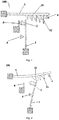
Fig. 1 is a schematic view of an apparatus for in-situ testing impact strength of micro-structure according to an embodiment of the present disclosure, wherein the flexible beam is not loaded; -
Fig. 2 is a schematic view of an apparatus for in-situ testing impact strength of micro-structure according to an embodiment of the present disclosure, wherein the loaded flexible beam is being released, and wherein one end of the flexible beam is engaged to one of the plurality of locking teeth when the flexible beam is loaded; -
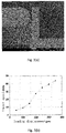
Fig. 3(a) is a local schematic view of electronic microscope photograph of the apparatus for in-situ testing impact strength of micro-structure according to an exemplary embodiment of the present disclosure; -
Fig. 3(b) is an schematic view of impact speed of the apparatus for in-situ testing impact strength of micro-structure according to an exemplary embodiment ofFig. 3(a) at different loading conditions and simulated by ansys software (ansys inc. America); and -
Fig. 3(c) is an schematic view of impact stress peak caused to the micro-structure by the apparatus for in-situ testing impact strength of micro-structure according to an exemplary embodiment ofFig. 3(a) at different loading conditions and simulated by ansys software (ansys inc. America). - Embodiments of the present disclosure will be explained in detail with reference to the drawings to make the configuration, advantages and effects apparent to the skilled person in the art.
- The present disclosure can also be implemented or applied by other embodiments, and every detail in the description can be modified and changed on basis of different views and applications without departing from the concept and scope of the present disclosure.
- According to a general concept of the present disclosure, an apparatus and a method for in-situ testing impact strength of micro-structure is designed. Specifically, while functional device with such micro-structure is manufactured, the functional device and the apparatus for in-situ testing impact strength of the micro-structure according to the present disclosure are manufactured on a silicon wafer with the functional device at the same time by the standard silicon on glass (SOG) bonding bulk silicon process (i.e. adding a testing area with the apparatus for in-situ testing impact strength of micro-structure according to the present disclosure onto the silicon wafer), meanwhile, a test simple of the micro-structure used in a later impact strength testing is manufactured at the apparatus under the same manufacturing conditions. After the functional device, the apparatus, and the test simple of the micro-structure are manufactured, an impact is applied on the test simple of the micro-structure by the apparatus, thus the impact strength test is performed and parameters of mechanical properties of the functional device can be achieved on line.
- Referring to
Figs. 1 and 2 , theapparatus 100 for in-situ testing impact strength of micro-structure according to an embodiment of the present disclosure comprises: aflexible beam 1, one end of which being fixed; animpact mass block 2, disposed at the other end of theflexible beam 1 and configured to exert an impact on a micro-structure; and a locking member 3, including abeam arm 31 and a plurality oflocking teeth 32, wherein thebeam arm 31 is perpendicular to theflexible beam 1, one end of thebeam arm 31 being fixed, and the plurality oflocking teeth 32 being distributed at intervals along thebeam arm 31, such that the other end of theflexible beam 1 is engaged to one of the plurality oflocking teeth 32 when theflexible beam 1 is loaded. - In the apparatus for in-situ testing impact strength of micro-structure according to embodiments of the present disclosure, a width w and a length l of the
flexible beam 1 determines the maximum impact energy created by the apparatus on the follow equation (1):
impact mass block 2 determine a scale of impact energy of the apparatus transmitted to the micro-structure, and the distribution of thelocking teeth 32 along the beam arm determines the minimum resolution of the impact strength testing of the whole apparatus. - At the time of testing, the micro-structure to be tested is provided at one end of the
flexible beam 1 provided with theimpact mass block 2, as shown inFig.1 . When the flexible beam is loaded, the end of the flexible beam provided with theimpact mass block 2 is engaged to one of the plurality oflocking teeth 32 by pushing theflexible beam 1 and /orbeam arm 31. Subsequently, a free end of thebeam arm 31 is continuously pushed until the end of theflexible beam 1 provided with theimpact mass block 2 is released from the engaged locking tooth, and instant impact is exerted on themicro-structure 6. - Compared with conventional testing method in which the whole functional device is impacted, such as sensors, the apparatus for in-situ testing impact strength of micro-structure of the present disclosure may test impact strength of the micro-structure more conveniently and accurately, which obviously shortens testing time, and is more helpful to feedback in design of the functional device such as sensors. Furthermore, since micro-structures may be tested, a complex structure may be divided into various micro-structures which may be tested one by one, thus the weakest area of the complex structure may easily be found.
- In an embodiment, the
apparatus 100 for in-situ testing impact strength of micro-structure of the present disclosure, the micro-structure 6 to be tested and a functional device (not shown in the drawings. such as sensor, etc.) are manufactured by the standard silicon on glass (SOG) bonding bulk silicon process, wherein the micro-structure 6 to be tested is a replicated sample of a micro-structure of the functional device, to perform the impact strength testing. During manufacturing process, patterns of the micro-structure 6, theapparatus 100 and the functional device are formed in the same photolithography process, and the movable silicon structures of the micro-structure, the apparatus, and the functional device are released in the same etching process. As such, it's ensured that the micro-structure 6 to be tested and the actual working functional device such as a sensor, have consistent impact strength, and interference caused by process errors is eliminated. - In an embodiment, the
apparatus 100 for in-situ testing impact strength of micro-structure of the present disclosure, the micro-structure 6 to be tested and a functional device (not shown in the drawings. such as a sensor, etc.) are manufactured by the standard silicon on glass (SOG) bonding bulk silicon process, such that theapparatus 100, the micro-structure 6 to be tested and the functional device are formed in the same micro unit, facilitating individual testing of every functional device. Through such configuration, at one hand, it is possible to perform an impact strength testing on each functional device; on the other hand, on the other hand, since a functional device such as a sensor is separated from a test area, the impact strength of the micro-structure could be tested on line, without damaging the actual working functional device, thus being superior to a traditional impact manner by which the entire functional device is damaged. - In an embodiment, the
apparatus 100 for in-situ testing impact strength of micro-structure of the present disclosure, the micro-structure 6 to be tested and the functional device (not shown in drawings. such as a sensor, etc.) are manufactured by the standard silicon on glass (SOG) bonding bulk silicon process, such that the micro-structure 6 is anchored on the silicon wafer (not shown) on which the functional device are provided, and is faced to theimpact mass block 2, and, one end of theflexible beam 1 and one end of thebeam arm 31 are anchored on the silicon wafer. - In an embodiment, a plurality of
locking teeth 32 are sequentially distributed at intervals along thebeam arm 31 from the free end of thebeam arm 31 and lengths of the teeth are reduced by an equal amount. However, the present disclosure is not limit thereto. The skilled person in the art may set the interval and tooth length of every locking teeth and number of the locking teeth according to actual testing resolution requirement. For example, in a preferred embodiment,locking teeth 32 are distributed at equal intervals and a line connecting each tooth tip forms a generally circular arc profile, as shown inFIG. 1 . - In an embodiment, size of the
impact mass block 2 is set to be substantially consistent with that of the micro-structure 6. The size and shape of theimpact mass block 2 may be changed with the size and shape of the micro-structure 6, thus, an impact load with high acceleration and high pulse width can be achieved. For example, in a preferred embodiment, one end of theimpact mass block 2 is arc-shaped, as shown inFigs. 1 and 2 . However, the present disclosure is not limited thereto. The skilled person in the art can select the shape and size of theimpact mass block 2 based on actual requirements, also can adjust the size of the impact mass block and the flexible beam simultaneously to obtain the impact load required. - In an embodiment, the
apparatus 100 for in-situ testing impact strength of micro-structure of a the present disclosure includes a first probe 4 for pushing the free end of thebeam arm 31 so as to load and/or release the free end of theflexible beam 1 engaged to one of the plurality oflocking teeth 32. In an embodiment, theapparatus 100 for testing impact strength of micro-structure of the present disclosure also includes a second probe 5 for pushing the free end of theflexible beam 1 so as to engage to one of the plurality oflocking teeth 32. It should be noted that the present disclosure is not limited thereto, the skilled person in the art can select any proper structure based on actual requirements as long as theflexible beam 1 and thebeam arm 32 are pushed to load and/or release the flexible beam. - In addition, the present disclosure also provides a method for in-situ testing impact strength of the micro-structure by the
apparatus 100, comprising the following steps: (a) fixing a micro-structure 6 so that the micro-structure faces an impact mass block; (b) loading theflexible beam 1 such that the other end (that is, the free end) of theflexible beam 1 is engaged to one of the plurality oflocking teeth 32 closest to the other end of theflexible beam 1; (c) releasing the other end of theflexible beam 1 so as to impact the micro-structure 6 through theimpact mass block 2 provided at the other end of theflexible beam 1; (d) repeating steps (b) and (c), such that the other end of theflexible beam 1 is engaged to every tooth of the plurality of lockingteeth 32 in the order from the nearest tooth to the farthest tooth and is released, until themicro-structure 6 is damaged; and (e) recording the position of the corresponding locking tooth when the micro-structure is damaged, and calculating corresponding load-deflection and obtaining corresponding impact strength. - Compared with conventional testing method of impacting the whole functional device, such as a sensor, the apparatus for in-situ testing impact strength of micro-structure of the present disclosure may test impact strength of the micro-structure more conveniently and accurately, which obviously shortens testing time, and is more helpful to feedback in design of the functional device such as sensors. Furthermore, since micro-structures may be tested, a complex structure may be divided into various micro-structures which may be tested one by one, thus the weakest area of the complex structure may easily be found.
- In an embodiment, the step (a) comprises: by the standard silicon on glass (SOG) bonding bulk silicon process, patterns of the
micro-structure 6, theapparatus 100 and the functional device are formed in the same photolithography process, and the movable silicon structures of the micro-structure, the apparatus, and the functional device are released in the same etching process, such that micro-structure is anchored on the silicon wafer on which the functional device are provided and is faced to the impact mass block, and one end of the flexible beam and one end of the beam arm are anchored on the silicon wafer. - In an embodiment, the step (c) comprises: pushing the free end of the
beam arm 31 by a first probe 4 so as to load and/or release the other end of theflexible beam 1. In another embodiment, the step (b) comprises: pushing the other end (i.e. the free end) of theflexible beam 1 by a second probe 5 to load and/or release the other end of theflexible beam 1. - In an embodiment, in step (e), building a mechanical model of the apparatus by LS-DYNA simulator of ansys software (ANSYS inc. America) which is a commercially available large general software of finite element analysis, inputting the corresponding load-deflection into the mechanical model of the apparatus, obtaining acceleration value at the time of instant impact through simulation, and thus obtaining impact strength at the time of instant impact between the impact mass block and the micro-structure.
- Next, an embodiment of the apparatus and method for in-situ testing impact strength of micro-structure of the present disclosure are described in detail with reference to
Figs. 3(a)-3(c) . - Firstly, a size of the apparatus for in-situ testing impact strength of micro-structure of the present disclosure is determined by the micro-structure to be tested. In the present embodiment, the micro-structure to be test is formed as a single tooth structure with a width of 20 micrometers and a length of 40 micrometers. The size of the impact
mass block 2 is similar with that of the micro-structure to be tested, that is, the impactmass block 2 is formed as a cube with an arc shape at a single side with a length of 40 micrometers and a width of 30 micrometers, as shown in the local schematic view of electronic microscope photograph ofFig. 3(a) . A size of theflexible beam 1 is required to be designed to ensure that the speed of the impact mass block is up to 10m/s at a moment before impacting the micro-structure to be tested. Thus, on the basis of energy storage equation of the flexible beam, relationship between the angular velocity and linear velocity, and the principle of conservation of energy, in the present embodiment, the size of the flexible beam is 700 micrometers long and 10 micrometers wide. Under such design, the instantaneous speed of the impact mass block at the moment before impact may be up to 20m/s. The design of locking teeth is determined on the basis of impact speed resolution requirement, the higher the resolution, the more intensive the locking teeth are arranged, that is, the number of the locking teeth is larger. In this example, the interval between the teeth is 10 micrometers. Meanwhile, the position of the locking teeth varies depending on the flexible beam. In the present embodiment, the locking position where the flexible beam is loaded is on a 1/4 circular sector contour formed by a radius of the flexible beam with the center being the end of the flexible beam, thus ensuring that the flexible beam is not blocked during a loading process. - In an embodiment, the
micro-structure 6, theapparatus 100 and the functional device such as sensors are manufactured by the standard silicon on glass (SOG) bonding bulk silicon process, all of which are formed in the same micro unit, patterns of which are defined in the same photolithography process, and also movable silicon structures are formed in the same etching process. - After the manufacturing process is completed, the apparatus for in-situ testing impact strength of a micro-structure according to the present embodiment is loaded and tested, for example, by probes. In this embodiment, a probe (eg, a second probe) is directly driven to load the flexible beam into the position of the corresponding locking tooth in an order from the nearest to the farthest, and then a locking operation is performed through another probe (eg, a first probe). After the whole system is stable, the flexible beam is released through the other probe, the impact result is recorded, and the test is repeated until the micro-structure to be tested is destructed by impact load. Then loading distance of the flexible beam is recorded, that is, the position of the locking tooth at this moment. In this embodiment, the destruction location is the twentieth locking tooth, that is, the load-deflection is 200 microns.
- Then, the impact failure deflection obtained by the test is inputted into the mechanical model built by the Ansys software of ANSYS Inc. (America), the impact process is simulated by the LS-DYNA module of the ANSYS software, and instantaneous impact acceleration of the impact between the impact mass block and the micro-structure under test in the condition that the deflection is 200 micrometers is obtained, which is the impact load ultimate strength value of the micro-structure under test.
Figs. 3(b) and3(c) show an impact speed schematic view and a schematic view of impact stress peak caused to the micro-structure at different loading conditions. In this example, the impact strength of the micro-structure under tested is 1.25Gpa. - The embodiments of the present disclosure described above illustrate the principle and the functions of the present disclosure by way of example only, rather than to limit the present disclosure. Those skilled in the art should understand that, without departing from the spirit and scope of the present disclosure, any changes and modifications to the disclosure are within the scope of the disclosure. The protection scope of the present disclosure should be as defined in the applied scope of the present application.
Claims (12)
- An apparatus for in-situ testing impact strength of a micro-structure, comprising:a flexible beam, one end of which being fixed;an impact mass block disposed at the other end of the flexible beam and configured to exert an impact on the micro-structure; anda locking member comprising a beam arm and a plurality of locking teeth, wherein the beam arm is perpendicular to the flexible beam and one end of the beam arm is fixed, and wherein the plurality of locking teeth are distributed at intervals along the beam arm, such that the other end of the flexible beam is engaged to one of the plurality of locking teeth when the flexible beam is loaded.
- The apparatus according to claim 1, wherein by the silicon on glass bonding bulk silicon process, patterns of the micro-structure, the apparatus and a functional device are formed in the same photolithography process, the functional device comprising the same structure with the micro-structure, and wherein the movable silicon structures of the micro-structure, the apparatus, and the functional device are released in the same etching process, such that micro-structure is anchored on the silicon wafer on which the functional device are provided and faces the impact mass block, and one end of the flexible beam and one end of the beam arm are anchored on the silicon wafer.
- The apparatus according to claim 1 or 2, wherein the plurality of locking teeth are sequentially distributed at intervals along the beam arm from the free end of the beam arm and lengths of the teeth are reduced by an equal amount.
- The apparatus according to any one of claims 1-3, further comprising:a first probe for pushing the other end of the beam arm so as to load and/or release the other end of the flexible beam engaged to one of the plurality of locking teeth.
- The apparatus according to claim 4, further comprising
a second probe for pushing the other end of the flexible beam so that the other end of the flexible beam is engaged to one of the plurality of locking teeth. - The apparatus according to any one of claims 1-3, wherein a size of the impact mass block is set to be substantially consistent with that of the micro-structure.
- The apparatus according to claim 6, wherein one end of the impact mass block is arc-shaped.
- A method for in-situ testing impact strength of a micro-structure using the apparatus according to claim 1, comprising:(a) fixing the micro-structure at one end so that the micro-structure faces the impact mass block;(b) loading the flexible beam such that the other end of the flexible beam is engaged to one of the plurality of locking teeth closest to the other end of the flexible beam;(c) releasing the other end of the flexible beam so as to impact the micro-structure through the impact mass block provided on the other end of the flexible beam;(d) repeating steps (b) and (c), such that the other end of the flexible beam is engaged to every tooth of the plurality of locking teeth in an order from the nearest tooth to the farthest tooth and is released, until the micro-structure is damaged; and(e) recording the position of the corresponding locking tooth when the micro-structure is damaged, calculating corresponding load-deflection and obtaining corresponding impact strength.
- The method according to claim 8, wherein step (a) comprises:by the silicon on glass bonding bulk silicon process, patterns of the micro-structure, the apparatus and a functional device are formed in the same photolithography process, the functional device comprising the same structure with the micro-structure, and wherein the movable silicon structures of the micro-structure, the apparatus, and the functional device are released in the same etching process, such that micro-structure is anchored on the silicon wafer on which the functional device are provided and faces the impact mass block, and one end of the flexible beam and one end of the beam arm are anchored on the silicon wafer.
- The method according to claim 8 or 9, wherein step (c) comprises: pushing the free end of the beam arm by the first probe so as to load and/or release the other end of the flexible beam.
- The method according to claim 10, wherein step (b) comprises: pushing the other end of the flexible beam by a second probe to load and/or release the other end of the flexible beam.
- The method according to claim 8 or 9, wherein step (e) comprises: inputting corresponding load-deflection into the mechanical model of the apparatus, and obtaining acceleration value at the time of instant impact between the impact mass block and the micro-structure.
Applications Claiming Priority (1)
| Application Number | Priority Date | Filing Date | Title |
|---|---|---|---|
| PCT/CN2015/080872 WO2016192100A1 (en) | 2015-06-05 | 2015-06-05 | Apparatus and method for testing impact strength of micro-structure on line |
Publications (3)
| Publication Number | Publication Date |
|---|---|
| EP3306298A1 true EP3306298A1 (en) | 2018-04-11 |
| EP3306298A4 EP3306298A4 (en) | 2019-02-20 |
| EP3306298B1 EP3306298B1 (en) | 2020-12-30 |
Family
ID=57439993
Family Applications (1)
| Application Number | Title | Priority Date | Filing Date |
|---|---|---|---|
| EP15893756.5A Active EP3306298B1 (en) | 2015-06-05 | 2015-06-05 | Apparatus and method for testing impact strength of micro-structure on line |
Country Status (3)
| Country | Link |
|---|---|
| US (1) | US10337970B2 (en) |
| EP (1) | EP3306298B1 (en) |
| WO (1) | WO2016192100A1 (en) |
Families Citing this family (1)
| Publication number | Priority date | Publication date | Assignee | Title |
|---|---|---|---|---|
| CN119492609B (en) * | 2024-10-29 | 2025-10-14 | 北京大学 | In-situ on-chip impact tensile strength online detection system and its manufacturing method and application |
Family Cites Families (11)
| Publication number | Priority date | Publication date | Assignee | Title |
|---|---|---|---|---|
| GB190825470A (en) * | 1908-11-26 | 1909-11-18 | Walter Longland | Improvements in and relating to Machines for Testing the Strength of Materials by Impact. |
| US4139814A (en) * | 1977-02-22 | 1979-02-13 | Continental Oil Company | Method of detecting corrosion at interface of concrete and reinforcing steel using a hydrogen probe imbedded in the concrete |
| JPS5621478A (en) | 1979-07-30 | 1981-02-27 | Fujitsu Ltd | Optical information reader |
| ES2176090B1 (en) * | 2000-07-13 | 2004-01-16 | Invest De Las Ind Ceramicas A | DEVICE AND EVALUATION OF EVALUATION OF THE RESISTANCE TO THE IMPACT OF FRAGILE MATERIALS. |
| US6595058B2 (en) * | 2001-06-19 | 2003-07-22 | Computed Ultrasound Global Inc. | Method and apparatus for determining dynamic response of microstructure by using pulsed broad bandwidth ultrasonic transducer as BAW hammer |
| JP4170923B2 (en) * | 2004-01-22 | 2008-10-22 | 富士通株式会社 | Impact test equipment |
| CN100460851C (en) * | 2005-12-07 | 2009-02-11 | 上海浩顺科技有限公司 | 1-D impaction strength testing device |
| JP4510068B2 (en) * | 2007-12-05 | 2010-07-21 | 東京エレクトロン株式会社 | Displacement measuring apparatus and displacement measuring method for microstructure |
| JP5621478B2 (en) * | 2010-09-29 | 2014-11-12 | Jfeスチール株式会社 | High toughness and high deformation steel plate for high strength steel pipe and method for producing the same |
| WO2012126718A1 (en) * | 2011-03-21 | 2012-09-27 | Asml Netherlands B.V. | Method and apparatus for determining structure parameters of microstructures |
| CN104330236A (en) * | 2013-07-22 | 2015-02-04 | 海洋王(东莞)照明科技有限公司 | Impact strength detection device |
-
2015
- 2015-06-05 EP EP15893756.5A patent/EP3306298B1/en active Active
- 2015-06-05 WO PCT/CN2015/080872 patent/WO2016192100A1/en not_active Ceased
- 2015-06-05 US US15/579,397 patent/US10337970B2/en active Active
Also Published As
| Publication number | Publication date |
|---|---|
| EP3306298B1 (en) | 2020-12-30 |
| US10337970B2 (en) | 2019-07-02 |
| EP3306298A4 (en) | 2019-02-20 |
| US20180149568A1 (en) | 2018-05-31 |
| WO2016192100A1 (en) | 2016-12-08 |
Similar Documents
| Publication | Publication Date | Title |
|---|---|---|
| Srikar et al. | The reliability of microelectromechanical systems (MEMS) in shock environments | |
| CN104296897B (en) | The satellite and the rocket six degree of freedom interfacial force computational methods of ring strain measurement are connected based on the satellite and the rocket | |
| JP2009139171A (en) | Displacement measuring apparatus and displacement measuring method for microstructure | |
| CN103954304A (en) | Zero offset short and long-term change value testing method applied to MEMS (Micro-electromechanical Systems) inertia unit | |
| Fang et al. | Shock destructive reliability analysis of electromagnetic MEMS micromirror for automotive LiDAR | |
| EP3306298B1 (en) | Apparatus and method for testing impact strength of micro-structure on line | |
| Li et al. | Reliability assessment of a MEMS microphone under mixed flowing gas environment and shock impact loading | |
| Yoon et al. | Shock-protection improvement using integrated novel shock-protection technologies | |
| Kimberley et al. | Failure of Au RF-MEMS switches subjected to dynamic loading | |
| Wang et al. | Dynamic response of a cantilever-type MEMS setback arming device under impact loads | |
| Sill | Testing techniques involved with the development of high shock acceleration sensors | |
| CN106370375B (en) | The novel heat of one kind drives on-line testing micro-structure impact strength test machine and detection method | |
| Sheehy et al. | The Failure Mechanisms of Micro‐Scale Cantilevers Under Shock and Vibration Stimuli | |
| CN106370330B (en) | A method based on on-chip impact strength detection testing machine using current change to detect microstructure impact impact stress wave pulse width and peak value | |
| Parkos et al. | Near-contact gas damping and dynamic response of high-g MEMS accelerometer beams | |
| Kuells et al. | Design of a 1D and 3D monolithically integrated piezoresistive MEMS high-g accelerometer | |
| CN106197933B (en) | A kind of heat drives shock machine and a kind of on-line detecting system and online test method | |
| Xue et al. | Development of a novel two axis piezoresistive micro accelerometer based on silicon | |
| Chen et al. | Wafer-level test system using a physical stimulus for a MEMS accelerometer | |
| CN104280569A (en) | Three-dimensional integrated micromachined acceleration sensor and manufacturing method for suppressing lateral interference | |
| Gildfind et al. | Use of acceleration and optical waypoint measurements to estimate piston trajectory in an impulse facility | |
| Kwon et al. | Wireless vibration sensor for tunnel construction | |
| KR20180019396A (en) | Similitude Law and Pseudodynamic Test Method of Reinforced Concrete Structure by Modifying Analytic Parameter Considering Measured Strain Data | |
| Spinner et al. | Electromechanical reliability testing of three-axial silicon force sensors | |
| Cheng et al. | On‐chip test method for in‐situ evaluating the impact resistance reliability of silicon microbeams |
Legal Events
| Date | Code | Title | Description |
|---|---|---|---|
| STAA | Information on the status of an ep patent application or granted ep patent |
Free format text: STATUS: THE INTERNATIONAL PUBLICATION HAS BEEN MADE |
|
| PUAI | Public reference made under article 153(3) epc to a published international application that has entered the european phase |
Free format text: ORIGINAL CODE: 0009012 |
|
| STAA | Information on the status of an ep patent application or granted ep patent |
Free format text: STATUS: REQUEST FOR EXAMINATION WAS MADE |
|
| 17P | Request for examination filed |
Effective date: 20171220 |
|
| AK | Designated contracting states |
Kind code of ref document: A1 Designated state(s): AL AT BE BG CH CY CZ DE DK EE ES FI FR GB GR HR HU IE IS IT LI LT LU LV MC MK MT NL NO PL PT RO RS SE SI SK SM TR |
|
| AX | Request for extension of the european patent |
Extension state: BA ME |
|
| RIN1 | Information on inventor provided before grant (corrected) |
Inventor name: LUO, KUI Inventor name: LIU, PENG Inventor name: LI, TING Inventor name: YANG, FANG Inventor name: ZHANG, LI Inventor name: TIAN, DAYU Inventor name: ZHANG, DACHENG Inventor name: WANG, WEI |
|
| DAV | Request for validation of the european patent (deleted) | ||
| DAX | Request for extension of the european patent (deleted) | ||
| REG | Reference to a national code |
Ref country code: DE Ref legal event code: R079 Ref document number: 602015064303 Country of ref document: DE Free format text: PREVIOUS MAIN CLASS: G01N0003000000 Ipc: G01N0003307000 |
|
| A4 | Supplementary search report drawn up and despatched |
Effective date: 20190122 |
|
| RIC1 | Information provided on ipc code assigned before grant |
Ipc: G01N 3/307 20060101AFI20190117BHEP |
|
| GRAP | Despatch of communication of intention to grant a patent |
Free format text: ORIGINAL CODE: EPIDOSNIGR1 |
|
| STAA | Information on the status of an ep patent application or granted ep patent |
Free format text: STATUS: GRANT OF PATENT IS INTENDED |
|
| INTG | Intention to grant announced |
Effective date: 20200915 |
|
| GRAS | Grant fee paid |
Free format text: ORIGINAL CODE: EPIDOSNIGR3 |
|
| GRAA | (expected) grant |
Free format text: ORIGINAL CODE: 0009210 |
|
| STAA | Information on the status of an ep patent application or granted ep patent |
Free format text: STATUS: THE PATENT HAS BEEN GRANTED |
|
| AK | Designated contracting states |
Kind code of ref document: B1 Designated state(s): AL AT BE BG CH CY CZ DE DK EE ES FI FR GB GR HR HU IE IS IT LI LT LU LV MC MK MT NL NO PL PT RO RS SE SI SK SM TR |
|
| REG | Reference to a national code |
Ref country code: GB Ref legal event code: FG4D |
|
| REG | Reference to a national code |
Ref country code: DE Ref legal event code: R096 Ref document number: 602015064303 Country of ref document: DE |
|
| REG | Reference to a national code |
Ref country code: AT Ref legal event code: REF Ref document number: 1350411 Country of ref document: AT Kind code of ref document: T Effective date: 20210115 |
|
| REG | Reference to a national code |
Ref country code: IE Ref legal event code: FG4D |
|
| PG25 | Lapsed in a contracting state [announced via postgrant information from national office to epo] |
Ref country code: RS Free format text: LAPSE BECAUSE OF FAILURE TO SUBMIT A TRANSLATION OF THE DESCRIPTION OR TO PAY THE FEE WITHIN THE PRESCRIBED TIME-LIMIT Effective date: 20201230 Ref country code: FI Free format text: LAPSE BECAUSE OF FAILURE TO SUBMIT A TRANSLATION OF THE DESCRIPTION OR TO PAY THE FEE WITHIN THE PRESCRIBED TIME-LIMIT Effective date: 20201230 Ref country code: NO Free format text: LAPSE BECAUSE OF FAILURE TO SUBMIT A TRANSLATION OF THE DESCRIPTION OR TO PAY THE FEE WITHIN THE PRESCRIBED TIME-LIMIT Effective date: 20210330 Ref country code: GR Free format text: LAPSE BECAUSE OF FAILURE TO SUBMIT A TRANSLATION OF THE DESCRIPTION OR TO PAY THE FEE WITHIN THE PRESCRIBED TIME-LIMIT Effective date: 20210331 |
|
| REG | Reference to a national code |
Ref country code: AT Ref legal event code: MK05 Ref document number: 1350411 Country of ref document: AT Kind code of ref document: T Effective date: 20201230 |
|
| PG25 | Lapsed in a contracting state [announced via postgrant information from national office to epo] |
Ref country code: BG Free format text: LAPSE BECAUSE OF FAILURE TO SUBMIT A TRANSLATION OF THE DESCRIPTION OR TO PAY THE FEE WITHIN THE PRESCRIBED TIME-LIMIT Effective date: 20210330 Ref country code: SE Free format text: LAPSE BECAUSE OF FAILURE TO SUBMIT A TRANSLATION OF THE DESCRIPTION OR TO PAY THE FEE WITHIN THE PRESCRIBED TIME-LIMIT Effective date: 20201230 Ref country code: LV Free format text: LAPSE BECAUSE OF FAILURE TO SUBMIT A TRANSLATION OF THE DESCRIPTION OR TO PAY THE FEE WITHIN THE PRESCRIBED TIME-LIMIT Effective date: 20201230 |
|
| REG | Reference to a national code |
Ref country code: NL Ref legal event code: MP Effective date: 20201230 |
|
| PG25 | Lapsed in a contracting state [announced via postgrant information from national office to epo] |
Ref country code: HR Free format text: LAPSE BECAUSE OF FAILURE TO SUBMIT A TRANSLATION OF THE DESCRIPTION OR TO PAY THE FEE WITHIN THE PRESCRIBED TIME-LIMIT Effective date: 20201230 |
|
| REG | Reference to a national code |
Ref country code: LT Ref legal event code: MG9D |
|
| PG25 | Lapsed in a contracting state [announced via postgrant information from national office to epo] |
Ref country code: SK Free format text: LAPSE BECAUSE OF FAILURE TO SUBMIT A TRANSLATION OF THE DESCRIPTION OR TO PAY THE FEE WITHIN THE PRESCRIBED TIME-LIMIT Effective date: 20201230 Ref country code: RO Free format text: LAPSE BECAUSE OF FAILURE TO SUBMIT A TRANSLATION OF THE DESCRIPTION OR TO PAY THE FEE WITHIN THE PRESCRIBED TIME-LIMIT Effective date: 20201230 Ref country code: PT Free format text: LAPSE BECAUSE OF FAILURE TO SUBMIT A TRANSLATION OF THE DESCRIPTION OR TO PAY THE FEE WITHIN THE PRESCRIBED TIME-LIMIT Effective date: 20210430 Ref country code: CZ Free format text: LAPSE BECAUSE OF FAILURE TO SUBMIT A TRANSLATION OF THE DESCRIPTION OR TO PAY THE FEE WITHIN THE PRESCRIBED TIME-LIMIT Effective date: 20201230 Ref country code: EE Free format text: LAPSE BECAUSE OF FAILURE TO SUBMIT A TRANSLATION OF THE DESCRIPTION OR TO PAY THE FEE WITHIN THE PRESCRIBED TIME-LIMIT Effective date: 20201230 Ref country code: LT Free format text: LAPSE BECAUSE OF FAILURE TO SUBMIT A TRANSLATION OF THE DESCRIPTION OR TO PAY THE FEE WITHIN THE PRESCRIBED TIME-LIMIT Effective date: 20201230 |
|
| PG25 | Lapsed in a contracting state [announced via postgrant information from national office to epo] |
Ref country code: AT Free format text: LAPSE BECAUSE OF FAILURE TO SUBMIT A TRANSLATION OF THE DESCRIPTION OR TO PAY THE FEE WITHIN THE PRESCRIBED TIME-LIMIT Effective date: 20201230 Ref country code: PL Free format text: LAPSE BECAUSE OF FAILURE TO SUBMIT A TRANSLATION OF THE DESCRIPTION OR TO PAY THE FEE WITHIN THE PRESCRIBED TIME-LIMIT Effective date: 20201230 |
|
| PG25 | Lapsed in a contracting state [announced via postgrant information from national office to epo] |
Ref country code: IS Free format text: LAPSE BECAUSE OF FAILURE TO SUBMIT A TRANSLATION OF THE DESCRIPTION OR TO PAY THE FEE WITHIN THE PRESCRIBED TIME-LIMIT Effective date: 20210430 |
|
| REG | Reference to a national code |
Ref country code: DE Ref legal event code: R097 Ref document number: 602015064303 Country of ref document: DE |
|
| PG25 | Lapsed in a contracting state [announced via postgrant information from national office to epo] |
Ref country code: IT Free format text: LAPSE BECAUSE OF FAILURE TO SUBMIT A TRANSLATION OF THE DESCRIPTION OR TO PAY THE FEE WITHIN THE PRESCRIBED TIME-LIMIT Effective date: 20201230 Ref country code: AL Free format text: LAPSE BECAUSE OF FAILURE TO SUBMIT A TRANSLATION OF THE DESCRIPTION OR TO PAY THE FEE WITHIN THE PRESCRIBED TIME-LIMIT Effective date: 20201230 |
|
| PLBE | No opposition filed within time limit |
Free format text: ORIGINAL CODE: 0009261 |
|
| STAA | Information on the status of an ep patent application or granted ep patent |
Free format text: STATUS: NO OPPOSITION FILED WITHIN TIME LIMIT |
|
| PG25 | Lapsed in a contracting state [announced via postgrant information from national office to epo] |
Ref country code: DK Free format text: LAPSE BECAUSE OF FAILURE TO SUBMIT A TRANSLATION OF THE DESCRIPTION OR TO PAY THE FEE WITHIN THE PRESCRIBED TIME-LIMIT Effective date: 20201230 |
|
| 26N | No opposition filed |
Effective date: 20211001 |
|
| PG25 | Lapsed in a contracting state [announced via postgrant information from national office to epo] |
Ref country code: ES Free format text: LAPSE BECAUSE OF FAILURE TO SUBMIT A TRANSLATION OF THE DESCRIPTION OR TO PAY THE FEE WITHIN THE PRESCRIBED TIME-LIMIT Effective date: 20201230 |
|
| PG25 | Lapsed in a contracting state [announced via postgrant information from national office to epo] |
Ref country code: SI Free format text: LAPSE BECAUSE OF FAILURE TO SUBMIT A TRANSLATION OF THE DESCRIPTION OR TO PAY THE FEE WITHIN THE PRESCRIBED TIME-LIMIT Effective date: 20201230 |
|
| REG | Reference to a national code |
Ref country code: BE Ref legal event code: MM Effective date: 20210630 |
|
| PG25 | Lapsed in a contracting state [announced via postgrant information from national office to epo] |
Ref country code: IS Free format text: LAPSE BECAUSE OF FAILURE TO SUBMIT A TRANSLATION OF THE DESCRIPTION OR TO PAY THE FEE WITHIN THE PRESCRIBED TIME-LIMIT Effective date: 20210430 |
|
| PG25 | Lapsed in a contracting state [announced via postgrant information from national office to epo] |
Ref country code: BE Free format text: LAPSE BECAUSE OF NON-PAYMENT OF DUE FEES Effective date: 20210630 |
|
| PGFP | Annual fee paid to national office [announced via postgrant information from national office to epo] |
Ref country code: MC Payment date: 20220621 Year of fee payment: 8 Ref country code: LU Payment date: 20220621 Year of fee payment: 8 Ref country code: IE Payment date: 20220518 Year of fee payment: 8 Ref country code: GB Payment date: 20220530 Year of fee payment: 8 Ref country code: FR Payment date: 20220512 Year of fee payment: 8 Ref country code: DE Payment date: 20220621 Year of fee payment: 8 |
|
| PGFP | Annual fee paid to national office [announced via postgrant information from national office to epo] |
Ref country code: CH Payment date: 20220629 Year of fee payment: 8 |
|
| PG25 | Lapsed in a contracting state [announced via postgrant information from national office to epo] |
Ref country code: NL Free format text: LAPSE BECAUSE OF NON-PAYMENT OF DUE FEES Effective date: 20201230 Ref country code: CY Free format text: LAPSE BECAUSE OF FAILURE TO SUBMIT A TRANSLATION OF THE DESCRIPTION OR TO PAY THE FEE WITHIN THE PRESCRIBED TIME-LIMIT Effective date: 20201230 |
|
| PG25 | Lapsed in a contracting state [announced via postgrant information from national office to epo] |
Ref country code: SM Free format text: LAPSE BECAUSE OF FAILURE TO SUBMIT A TRANSLATION OF THE DESCRIPTION OR TO PAY THE FEE WITHIN THE PRESCRIBED TIME-LIMIT Effective date: 20201230 Ref country code: HU Free format text: LAPSE BECAUSE OF FAILURE TO SUBMIT A TRANSLATION OF THE DESCRIPTION OR TO PAY THE FEE WITHIN THE PRESCRIBED TIME-LIMIT; INVALID AB INITIO Effective date: 20150605 |
|
| REG | Reference to a national code |
Ref country code: DE Ref legal event code: R119 Ref document number: 602015064303 Country of ref document: DE |
|
| PG25 | Lapsed in a contracting state [announced via postgrant information from national office to epo] |
Ref country code: MC Free format text: LAPSE BECAUSE OF NON-PAYMENT OF DUE FEES Effective date: 20230630 |
|
| PG25 | Lapsed in a contracting state [announced via postgrant information from national office to epo] |
Ref country code: MC Free format text: LAPSE BECAUSE OF NON-PAYMENT OF DUE FEES Effective date: 20230630 |
|
| REG | Reference to a national code |
Ref country code: CH Ref legal event code: PL |
|
| GBPC | Gb: european patent ceased through non-payment of renewal fee |
Effective date: 20230605 |
|
| PG25 | Lapsed in a contracting state [announced via postgrant information from national office to epo] |
Ref country code: LU Free format text: LAPSE BECAUSE OF NON-PAYMENT OF DUE FEES Effective date: 20230605 |
|
| REG | Reference to a national code |
Ref country code: IE Ref legal event code: MM4A |
|
| PG25 | Lapsed in a contracting state [announced via postgrant information from national office to epo] |
Ref country code: LU Free format text: LAPSE BECAUSE OF NON-PAYMENT OF DUE FEES Effective date: 20230605 |
|
| PG25 | Lapsed in a contracting state [announced via postgrant information from national office to epo] |
Ref country code: IE Free format text: LAPSE BECAUSE OF NON-PAYMENT OF DUE FEES Effective date: 20230605 |
|
| PG25 | Lapsed in a contracting state [announced via postgrant information from national office to epo] |
Ref country code: MK Free format text: LAPSE BECAUSE OF FAILURE TO SUBMIT A TRANSLATION OF THE DESCRIPTION OR TO PAY THE FEE WITHIN THE PRESCRIBED TIME-LIMIT Effective date: 20201230 Ref country code: IE Free format text: LAPSE BECAUSE OF NON-PAYMENT OF DUE FEES Effective date: 20230605 Ref country code: DE Free format text: LAPSE BECAUSE OF NON-PAYMENT OF DUE FEES Effective date: 20240103 Ref country code: GB Free format text: LAPSE BECAUSE OF NON-PAYMENT OF DUE FEES Effective date: 20230605 Ref country code: CH Free format text: LAPSE BECAUSE OF NON-PAYMENT OF DUE FEES Effective date: 20230630 |
|
| PG25 | Lapsed in a contracting state [announced via postgrant information from national office to epo] |
Ref country code: FR Free format text: LAPSE BECAUSE OF NON-PAYMENT OF DUE FEES Effective date: 20230630 |
|
| PG25 | Lapsed in a contracting state [announced via postgrant information from national office to epo] |
Ref country code: TR Free format text: LAPSE BECAUSE OF FAILURE TO SUBMIT A TRANSLATION OF THE DESCRIPTION OR TO PAY THE FEE WITHIN THE PRESCRIBED TIME-LIMIT Effective date: 20201230 |
|
| PG25 | Lapsed in a contracting state [announced via postgrant information from national office to epo] |
Ref country code: MT Free format text: LAPSE BECAUSE OF FAILURE TO SUBMIT A TRANSLATION OF THE DESCRIPTION OR TO PAY THE FEE WITHIN THE PRESCRIBED TIME-LIMIT Effective date: 20201230 |