EP3306275B1 - Sealed sensor for operating in a corrosive environment - Google Patents
Sealed sensor for operating in a corrosive environment Download PDFInfo
- Publication number
- EP3306275B1 EP3306275B1 EP16306327.4A EP16306327A EP3306275B1 EP 3306275 B1 EP3306275 B1 EP 3306275B1 EP 16306327 A EP16306327 A EP 16306327A EP 3306275 B1 EP3306275 B1 EP 3306275B1
- Authority
- EP
- European Patent Office
- Prior art keywords
- seal
- sensor
- housing
- wire
- compressor
- Prior art date
- Legal status (The legal status is an assumption and is not a legal conclusion. Google has not performed a legal analysis and makes no representation as to the accuracy of the status listed.)
- Active
Links
Images
Classifications
-
- G—PHYSICS
- G01—MEASURING; TESTING
- G01D—MEASURING NOT SPECIALLY ADAPTED FOR A SPECIFIC VARIABLE; ARRANGEMENTS FOR MEASURING TWO OR MORE VARIABLES NOT COVERED IN A SINGLE OTHER SUBCLASS; TARIFF METERING APPARATUS; MEASURING OR TESTING NOT OTHERWISE PROVIDED FOR
- G01D11/00—Component parts of measuring arrangements not specially adapted for a specific variable
- G01D11/24—Housings ; Casings for instruments
- G01D11/245—Housings for sensors
-
- G—PHYSICS
- G01—MEASURING; TESTING
- G01D—MEASURING NOT SPECIALLY ADAPTED FOR A SPECIFIC VARIABLE; ARRANGEMENTS FOR MEASURING TWO OR MORE VARIABLES NOT COVERED IN A SINGLE OTHER SUBCLASS; TARIFF METERING APPARATUS; MEASURING OR TESTING NOT OTHERWISE PROVIDED FOR
- G01D11/00—Component parts of measuring arrangements not specially adapted for a specific variable
- G01D11/24—Housings ; Casings for instruments
- G01D11/26—Windows; Cover glasses; Sealings therefor
Definitions
- the invention concerns a sensor, in particular a wired sensor.
- a conventional rotary machine such as a compressor or a turboexpander used in the Oil and Gas industry for the extraction and transportation of the gas or the oil comprises several sensors for controlling or monitoring some parameters such as displacement, speed, temperature, vibration, presence or not of a component. These sensors are often wired, and sometimes in contact with a process gas such as natural gas at pressures up to several hundred bars. Unfortunately this natural gas is corrosive because contains corrosive contaminants or materials such as hydrogen sulfide (H2S), carbon dioxide (CO2) and water.
- H2S hydrogen sulfide
- CO2 carbon dioxide
- US 2015/377659A1 discloses a detector assembly for operating in an environment subjected to gases or liquids under pressure.
- the aim of the invention is to provide a sensor of an electric motor or a magnetic bearing, for measuring a position, a displacement, a speed, a rotational speed, an acceleration, a temperature, a pressure or a vibration, and for operating in an environment subjected to corrosive gases or liquids under pressure.
- the invention concerns a sensor comprising a housing inside which are installed a sensing portion, at least one wire electrically connected to the sensing portion, and a seal for sealing the connection between the sensing portion and the wire.
- the seal comprises at least one through-hole receiving a portion of the wire.
- the sensor comprises also a compressor installed at least partly inside the housing, movable with respect to the housing and adapted to contact the seal in order to compress it. According to the invention, the displacement of the compressor deforms the seal so that a compression force is applied by the seal onto said portion of the wire.
- such a sensor may incorporate one or several of the following features:
- Another object of the invention is the installation or the use of a sensor according to the invention in an electrical motor or a magnetic bearing.
- Figures 1 and 2 show a sensor 1 centered on a central axis X1.
- the sensor 1 comprises a housing 2 hosting a sensing portion 3 which is connected at least electrically to at least one wire 4 which extends at least partly inside the housing 2.
- the sensing portion 3 of the sensor 1 senses one or several parameters among position, displacement, speed, rotational speed, acceleration, vibration, temperature, pressure, presence or not of an element or a substance, in an electrical motor or a magnetic bearing.
- the sensor 1 measures the rotational speed of a rotor of an active magnetic bearing.
- the wire 4 comprises an electrical conductor (not represented) surrounded by an outer insulator (not represented).
- the insulator isolates the electrical conductor both electrically and chemically from its environment.
- the insulator is made of FEP or PTFE or a ribbon comprising Kapton and Daglass materials.
- the wire 4 is connected to the sensing portion 3 at one of its ends, whereas the other end is coming out of the housing 2.
- the wire 4 delivers electrical signals from and/or to the sensing portion 3.
- the housing 2 also receives a seal 5 to protect the electrical connection between the sensing portion 3 and the wire 4, and in particular the conductor of the wire 4.
- the seal 5 is deformable in all directions.
- the seal 5 is monobloc.
- the seal 5 is made of a material which is softer than the material constituting the housing 2.
- the seal 5 is made from a synthetic material such as a thermoplastic material.
- the seal 5 is made from a material resistant to high temperatures and to corrosive substances.
- the seal 5 is made from PTFE or FEP.
- the seal 5 is in the shape of an annular disc.
- the outer periphery of the disc is facing an inner cylindrical portion of the housing 2.
- the outer diameter of the seal in a non-deformed state is slightly smaller than the diameter of the inner cylindrical portion of the housing 2, so as to easy the installation of the seal inside the housing 2 upon assembly of the sensor 1.
- the seal 5 comprises at least one through-hole 6 receiving a portion of the wire 4.
- the seal 5 is in a non-deformed state, a small clearance exists between the portion of the wire 4 and the trough-hole, in order to easy the installation of the wire 4 through the seal 5.
- the housing 2 further receives a compressor 7 which is at least partly installed inside the housing 2.
- the compressor is movable with respect to the housing 2.
- the compressor 7 is adapted to contact the seal 5 in order to compress it. Upon this compression, the seal 5 deforms in such a way that a compression force exerted by the seal 5 onto said portion of the at least one wire 4 builds up, so as to prevent any passage of corrosive gases or liquids between the seal 5 and the at least one wire 4.
- the compressor 7 comprises a nut 9 and an upper plate 8.
- the upper plate 8 compresses the seal 5.
- the upper plate 8 is ring-shaped and translates along central axis X1 inside the housing 2.
- the upper plate 8 is in contact with the housing 2.
- the upper plate (8) comprises anti-rotation means (10) cooperating with the housing (2) so as to prevent any rotation of the upper plate (8) around central axis X1 upon rotation of the nut (9). This prevents any twisting of the seal along X1, which would result in a twisting of the wire(s) 4 and/or potential damage to the wire(s) 4 or its electrical connection to the sensing portion 3.
- the anti-rotation means 10 consists of at least one flat surface on the outer periphery of the upper plate 8. This flat surface cooperates by contact with a mating flat surface of the housing 2.
- the housing 2 also hosts a lower plate 11 against which the seal 5 bears.
- the housing 2 comprises blocking means 14 against which bears the lower plate 11.
- the lower plate 11 is opposite the compressor 7 with respect to the seal 5. Upon tightening of the nut 9, the seal is compressed between the upper plate 8, the lower plate 11 and the housing 2.
- the blocking means 14 prevent any axial movement of the lower plate 11, that is to say in a direction parallel to the central axis X1, and in particular in the direction opposite to the sensing portion 3 of the sensor 1.
- the blocking means 14 consists of a annular chamfer.
- the angle of the chamfer with respect to central axis X1 is 45°.
- the sensor 1 comprises two wires 4 and the seal 5 comprises two through-holes 6, each through-hole 6 receiving one wire 4.
- the lower plate 11, the upper plate 8 and the nut 9 each comprises at least one through-hole for the passage of the at least one wire 4.
- Central axis X1 is a common symmetry axis for the housing 2, the seal 5, the compressor 7, the lower plate 11, the upper plate 8 and the nut 9.
- the sensor further comprises installation means 12 for installing or attaching the sensor to an element.
- the installation means 12 consists of 2 through-holes through which screws or bolts (not represented) can be inserted. Any other suitable known attachment means can be used, based on the requirements of the application and the environment where the sensor 1 is used.
- the sensor 1 is installed onto the stator of a rotary electrical machine and measures a parameter of the rotor of the rotary electrical machine.
- the housing is filled with potting material 13.
- the potting material 13 occupies at least partly the free space inside the housing.
- some potting material is dispensed in the area where the electrical connection between the wire 4 and the sensing portion 3 is made.
- some potting material is dispensed in other areas such as the ones comprising the seal 5 and/or the compressor 7.
- the sensor 1 is assembled in the following way.
- one end of the wire(s) 4 is electrically connected to the sensing portion 3, the other end of the wire(s) 4 remaining in a free state.
- This free end of the wire(s) 4 is then inserted by order through the lower plate 11, the seal 5, the upper plate 8 and the nut 9.
- the obtained arrangement is then installed inside the housing 2 of the sensor 1.
- Some potting material 13 is dispensed inside the housing 2 in the area where the electrical connection between the wire 4 and the sensing portion 3 is made.
- the nut 9 is then tightened by applying a predetermined displacement or torque value until the seal 5 hermetically seals that area of electrical connection.
- some potting material 13 is dispensed in the compressor 7, in particular in the through-holes of the upper plate 8 and the nut 9.
- the electrical connection between the wire(s) 4 and the sensing portion 3 is hermetically sealed from the outside of the sensor 1, permanently but reversibly.
Landscapes
- Physics & Mathematics (AREA)
- General Physics & Mathematics (AREA)
- Structures Of Non-Positive Displacement Pumps (AREA)
- Transmission And Conversion Of Sensor Element Output (AREA)
Description
- The invention concerns a sensor, in particular a wired sensor.
- A conventional rotary machine such as a compressor or a turboexpander used in the Oil and Gas industry for the extraction and transportation of the gas or the oil comprises several sensors for controlling or monitoring some parameters such as displacement, speed, temperature, vibration, presence or not of a component. These sensors are often wired, and sometimes in contact with a process gas such as natural gas at pressures up to several hundred bars. Unfortunately this natural gas is corrosive because contains corrosive contaminants or materials such as hydrogen sulfide (H2S), carbon dioxide (CO2) and water.
- Efforts have been made recently to improve the resistance to the corrosion of the sensors by using special materials such as stainless steels, PTFE or FEP.
- However, the sealing of the sensor remains problematic, and it is still very difficult today to ensure no entrance of any corrosive and/or conductive fluid in the area of the sensor where electrical connections with the wire(s) are made.
-
US 2015/377659A1 discloses a detector assembly for operating in an environment subjected to gases or liquids under pressure. - Consequently, there is room for improvement.
- The aim of the invention is to provide a sensor of an electric motor or a magnetic bearing, for measuring a position, a displacement, a speed, a rotational speed, an acceleration, a temperature, a pressure or a vibration, and for operating in an environment subjected to corrosive gases or liquids under pressure.
- To this end, the invention concerns a sensor comprising a housing inside which are installed a sensing portion, at least one wire electrically connected to the sensing portion, and a seal for sealing the connection between the sensing portion and the wire. The seal comprises at least one through-hole receiving a portion of the wire. The sensor comprises also a compressor installed at least partly inside the housing, movable with respect to the housing and adapted to contact the seal in order to compress it. According to the invention, the displacement of the compressor deforms the seal so that a compression force is applied by the seal onto said portion of the wire.
- Thanks to the invention, no passage of corrosive gases or liquids between the seal and the wire is possible.
- According to further aspects of the invention which are advantageous but not compulsory, such a sensor may incorporate one or several of the following features:
- The deformation of the seal creates another compression force of the seal onto an inner portion of the housing so as to prevent any passage of corrosive gases or liquids between the seal and the housing;
- The compressor comprises a nut and an upper plate which compresses the seal upon tightening of the nut;
- The upper plate comprises anti-rotation means cooperating with the housing so as to prevent any rotation of the upper plate upon rotation of the nut;
- The anti-rotation means consists of at least one flat surface cooperating with a mating flat surface of the housing;
- The seal bears against a lower plate installed inside the housing opposite the compressor with respect to the seal;
- The seal is made of PTFE or FEP and the wire comprises an outer insulator made of FEP or PTFE or a ribbon comprising Kapton and Daglass materials;
- Some potting material is dispensed inside the housing for improving the sealing of the electrical connection between the wire and the sensing portion.
- Another object of the invention is the installation or the use of a sensor according to the invention in an electrical motor or a magnetic bearing.
- The invention will now be explained in correspondence with the annexed figures, and as an illustrative example, without restricting the object of the invention. In the annexed figures:
-
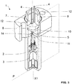
Figure 1 is a perspective view of a preferred embodiment of sensor according to the invention, where one quarter has been removed in order to better visualize the interior of the sensor; -
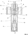
Figure 2 is a longitudinal sectional view of the sensor offigure 1 in the plan P. -
Figures 1 and2 show a sensor 1 centered on a central axis X1. - The sensor 1 comprises a
housing 2 hosting asensing portion 3 which is connected at least electrically to at least onewire 4 which extends at least partly inside thehousing 2. - The
sensing portion 3 of the sensor 1 senses one or several parameters among position, displacement, speed, rotational speed, acceleration, vibration, temperature, pressure, presence or not of an element or a substance, in an electrical motor or a magnetic bearing. For example, the sensor 1 measures the rotational speed of a rotor of an active magnetic bearing. - The
wire 4 comprises an electrical conductor (not represented) surrounded by an outer insulator (not represented). The insulator isolates the electrical conductor both electrically and chemically from its environment. Advantageously, the insulator is made of FEP or PTFE or a ribbon comprising Kapton and Daglass materials. - The
wire 4 is connected to thesensing portion 3 at one of its ends, whereas the other end is coming out of thehousing 2. - The
wire 4 delivers electrical signals from and/or to thesensing portion 3. - The
housing 2 also receives aseal 5 to protect the electrical connection between thesensing portion 3 and thewire 4, and in particular the conductor of thewire 4. - The
seal 5 is deformable in all directions. - The
seal 5 is monobloc. - The
seal 5 is made of a material which is softer than the material constituting thehousing 2. - The
seal 5 is made from a synthetic material such as a thermoplastic material. - The
seal 5 is made from a material resistant to high temperatures and to corrosive substances. - Advantageously, the
seal 5 is made from PTFE or FEP. - The
seal 5 is in the shape of an annular disc. The outer periphery of the disc is facing an inner cylindrical portion of thehousing 2. Preferably, the outer diameter of the seal in a non-deformed state is slightly smaller than the diameter of the inner cylindrical portion of thehousing 2, so as to easy the installation of the seal inside thehousing 2 upon assembly of the sensor 1. - The
seal 5 comprises at least one through-hole 6 receiving a portion of thewire 4. When theseal 5 is in a non-deformed state, a small clearance exists between the portion of thewire 4 and the trough-hole, in order to easy the installation of thewire 4 through theseal 5. - The
housing 2 further receives acompressor 7 which is at least partly installed inside thehousing 2. The compressor is movable with respect to thehousing 2. - The
compressor 7 is adapted to contact theseal 5 in order to compress it. Upon this compression, theseal 5 deforms in such a way that a compression force exerted by theseal 5 onto said portion of the at least onewire 4 builds up, so as to prevent any passage of corrosive gases or liquids between theseal 5 and the at least onewire 4. - Further, when the
seal 5 deforms, another compression force of theseal 5 onto the inner portion of thehousing 2 builds up, so as to prevent any passage of corrosive gases or liquids between theseal 5 and thehousing 2. - In the illustrated preferred embodiment of the invention, the
compressor 7 comprises anut 9 and anupper plate 8. Upon tightening of thenut 9 along central X1, theupper plate 8 compresses theseal 5. Theupper plate 8 is ring-shaped and translates along central axis X1 inside thehousing 2. Theupper plate 8 is in contact with thehousing 2. - Advantageously, the upper plate (8) comprises anti-rotation means (10) cooperating with the housing (2) so as to prevent any rotation of the upper plate (8) around central axis X1 upon rotation of the nut (9). This prevents any twisting of the seal along X1, which would result in a twisting of the wire(s) 4 and/or potential damage to the wire(s) 4 or its electrical connection to the
sensing portion 3. - In a preferred embodiment, as visible on
fig. 1 , the anti-rotation means 10 consists of at least one flat surface on the outer periphery of theupper plate 8. This flat surface cooperates by contact with a mating flat surface of thehousing 2. - The
housing 2 also hosts alower plate 11 against which theseal 5 bears. Thehousing 2 comprises blocking means 14 against which bears thelower plate 11. Thelower plate 11 is opposite thecompressor 7 with respect to theseal 5. Upon tightening of thenut 9, the seal is compressed between theupper plate 8, thelower plate 11 and thehousing 2. - The blocking means 14 prevent any axial movement of the
lower plate 11, that is to say in a direction parallel to the central axis X1, and in particular in the direction opposite to thesensing portion 3 of the sensor 1. - In the illustrated embodiment of the invention, the blocking means 14 consists of a annular chamfer. Preferably, the angle of the chamfer with respect to central axis X1 is 45°.
- Still in the illustrated embodiment, the sensor 1 comprises two
wires 4 and theseal 5 comprises two through-holes 6, each through-hole 6 receiving onewire 4. - The
lower plate 11, theupper plate 8 and thenut 9 each comprises at least one through-hole for the passage of the at least onewire 4. - Central axis X1 is a common symmetry axis for the
housing 2, theseal 5, thecompressor 7, thelower plate 11, theupper plate 8 and thenut 9. - The sensor further comprises installation means 12 for installing or attaching the sensor to an element. On the illustrated preferred embodiment of the invention, the installation means 12 consists of 2 through-holes through which screws or bolts (not represented) can be inserted. Any other suitable known attachment means can be used, based on the requirements of the application and the environment where the sensor 1 is used. For example, the sensor 1 is installed onto the stator of a rotary electrical machine and measures a parameter of the rotor of the rotary electrical machine.
- In order to further enhance the sealing of the electrical connection between the sensing
portion 3 and thewire 4, the housing is filled withpotting material 13. - The potting
material 13 occupies at least partly the free space inside the housing. - In particular, some potting material is dispensed in the area where the electrical connection between the
wire 4 and thesensing portion 3 is made. - Alternatively or in addition, some potting material is dispensed in other areas such as the ones comprising the
seal 5 and/or thecompressor 7. - The sensor 1 is assembled in the following way. In a first step, one end of the wire(s) 4 is electrically connected to the
sensing portion 3, the other end of the wire(s) 4 remaining in a free state. This free end of the wire(s) 4 is then inserted by order through thelower plate 11, theseal 5, theupper plate 8 and thenut 9. The obtained arrangement is then installed inside thehousing 2 of the sensor 1. Some pottingmaterial 13 is dispensed inside thehousing 2 in the area where the electrical connection between thewire 4 and thesensing portion 3 is made. Thenut 9 is then tightened by applying a predetermined displacement or torque value until theseal 5 hermetically seals that area of electrical connection. Finally, some pottingmaterial 13 is dispensed in thecompressor 7, in particular in the through-holes of theupper plate 8 and thenut 9. - Thanks to the invention, the electrical connection between the wire(s) 4 and the
sensing portion 3 is hermetically sealed from the outside of the sensor 1, permanently but reversibly. - In addition, technical features of the different embodiments can be, in whole or part, combined with each other.
-
- X1 central axis
- 1 sensor
- 2 housing
- 3 sensing portion
- 4 wire
- 5 seal
- 6 through-hole
- 7 compressor
- 8 upper plate
- 9 nut
- 10 anti-rotation means
- 11 lower plate
- 12 installation means
- 13 potting material
- 14 blocking means
Claims (10)
- A sensor (1) of an electric motor or a magnetic bearing, for measuring a position, a displacement, a speed, a rotational speed, an acceleration, a temperature, a pressure or a vibration, and for operating in an environment subjected to corrosive gases or liquids under pressure, comprising a housing (2) inside which are installed:- a sensing portion (3),- at least one wire (4) electrically connected to the sensing portion (3), and- a seal (5) for sealing the connection between the sensing portion (3) and the at least one wire (4), with at least one through-hole (6) receiving a portion of the at least one wire (4),the sensor (1) further comprising a compressor (7) installed at least partly inside the housing (2), movable with respect to the housing (2) and adapted to contact the seal (5) in order to compress it,
wherein upon displacement of the compressor (7), the seal (5) is deformed until the creation of a compression force exerted by the seal (5) onto said portion of the at least one wire (4), so as to prevent any passage of corrosive gases or liquids between the seal (5) and the at least one wire (4). - Sensor (1) according to claim 1 characterized in that the deformation the seal (5) creates another compression force of the seal (5) onto an inner portion of the housing (2) so as to prevent any passage of corrosive gases or liquids between the seal (5) and the housing (2).
- Sensor (1) according to claim 1 or 2, characterized in that compressor comprises a nut (9) and an upper plate (8), the upper plate (8) compressing the seal (5) upon tightening of the nut (9).
- Sensor (1) according to claim 3, characterized in that the upper plate (8) comprises anti-rotation means (10) cooperating with the housing (2) so as to prevent any rotation of the upper plate (8) upon rotation of the nut (9).
- Sensor (1) according to claim 4, characterized in that the anti-rotation means (10) consists of at least one flat surface cooperating with a mating flat surface of the housing (2).
- Sensor (1) according to any preceding claim, characterized in that the seal (5) bears against a lower plate (11) installed inside the housing (2) and opposite the compressor (7) with respect to the seal (5).
- Sensor (1) according to any preceding claim, characterized in that the seal (5) is made of PTFE or FEP and the at least one wire comprises an outer insulator made of FEP or PTFE or a ribbon comprising Kapton and Daglass materials.
- Sensor (1) according to any preceding claim, characterized in that the sensor comprises two wires (4) and that the seal (5) comprises two through-holes (6), each through-hole (6) receiving one wire (4).
- Sensor (1) according to any preceding claim, characterized in that some potting material (13) is dispensed inside the housing (2) so as to further improve the sealing of the electrical connection between the wire (4) and the sensing portion (3) of the sensor (1).
- Installation or use of a sensor (1) according to any of the preceding claims for measuring a position, a displacement, a speed, a rotational speed, an acceleration, a temperature, a pressure or a vibration in an electrical motor or a magnetic bearing.
Priority Applications (5)
| Application Number | Priority Date | Filing Date | Title |
|---|---|---|---|
| EP16306327.4A EP3306275B1 (en) | 2016-10-07 | 2016-10-07 | Sealed sensor for operating in a corrosive environment |
| CN202311765180.8A CN117870738A (en) | 2016-10-07 | 2017-08-02 | Sensor for detecting a position of a body |
| CN201710650562.4A CN107917724A (en) | 2016-10-07 | 2017-08-02 | sensor |
| JP2017168274A JP7139099B2 (en) | 2016-10-07 | 2017-09-01 | sensor |
| US15/725,778 US11415437B2 (en) | 2016-10-07 | 2017-10-05 | Sensor |
Applications Claiming Priority (1)
| Application Number | Priority Date | Filing Date | Title |
|---|---|---|---|
| EP16306327.4A EP3306275B1 (en) | 2016-10-07 | 2016-10-07 | Sealed sensor for operating in a corrosive environment |
Publications (2)
| Publication Number | Publication Date |
|---|---|
| EP3306275A1 EP3306275A1 (en) | 2018-04-11 |
| EP3306275B1 true EP3306275B1 (en) | 2020-07-15 |
Family
ID=57286405
Family Applications (1)
| Application Number | Title | Priority Date | Filing Date |
|---|---|---|---|
| EP16306327.4A Active EP3306275B1 (en) | 2016-10-07 | 2016-10-07 | Sealed sensor for operating in a corrosive environment |
Country Status (4)
| Country | Link |
|---|---|
| US (1) | US11415437B2 (en) |
| EP (1) | EP3306275B1 (en) |
| JP (1) | JP7139099B2 (en) |
| CN (2) | CN117870738A (en) |
Families Citing this family (3)
| Publication number | Priority date | Publication date | Assignee | Title |
|---|---|---|---|---|
| EP3306275B1 (en) | 2016-10-07 | 2020-07-15 | Skf Magnetic Mechatronics | Sealed sensor for operating in a corrosive environment |
| CN111307216A (en) * | 2020-03-11 | 2020-06-19 | 兰州中联电子科技有限公司 | Vibration temperature integral type sensing device based on temperature measurement vibration measurement system |
| WO2023010347A1 (en) * | 2021-08-04 | 2023-02-09 | Abb Schweiz Ag | Assemblies, circuits, and methods of transmitters between different equipment protection levels in a hazardous environment |
Citations (1)
| Publication number | Priority date | Publication date | Assignee | Title |
|---|---|---|---|---|
| US8357862B2 (en) * | 2009-07-24 | 2013-01-22 | Societe De Mecanique Magnetique | Pressurized rotary machine with hermetically sealed connections |
Family Cites Families (10)
| Publication number | Priority date | Publication date | Assignee | Title |
|---|---|---|---|---|
| US3794204A (en) * | 1971-08-13 | 1974-02-26 | Provident Tool Eng Co | Closure device |
| JPH0421085Y2 (en) * | 1985-01-25 | 1992-05-14 | ||
| US5170675A (en) * | 1990-07-30 | 1992-12-15 | Nsk Ltd. | Linear movement table apparatus |
| JPH08122165A (en) * | 1994-10-21 | 1996-05-17 | Yamatake Honeywell Co Ltd | Insertion type detector |
| DE10021059B4 (en) * | 2000-04-28 | 2006-06-29 | Hiss, Eckart, Dr. | sensor |
| US7341650B2 (en) * | 2003-06-27 | 2008-03-11 | Ngk Spark Plug Co., Ltd. | Method of manufacturing sensor and sensor |
| FR2994021B1 (en) * | 2012-07-27 | 2014-08-22 | Mecanique Magnetique Sa | ELECTRICAL CONNECTOR SEALED FOR MAGNETIC BEARINGS |
| CN111442791A (en) * | 2013-03-04 | 2020-07-24 | 德康公司 | Wire seal for detector assembly |
| DE102014010116B4 (en) * | 2013-04-29 | 2018-11-15 | Elmos Semiconductor Aktiengesellschaft | MEMS sensor for difficult environments and media |
| EP3306275B1 (en) | 2016-10-07 | 2020-07-15 | Skf Magnetic Mechatronics | Sealed sensor for operating in a corrosive environment |
-
2016
- 2016-10-07 EP EP16306327.4A patent/EP3306275B1/en active Active
-
2017
- 2017-08-02 CN CN202311765180.8A patent/CN117870738A/en active Pending
- 2017-08-02 CN CN201710650562.4A patent/CN107917724A/en active Pending
- 2017-09-01 JP JP2017168274A patent/JP7139099B2/en active Active
- 2017-10-05 US US15/725,778 patent/US11415437B2/en active Active
Patent Citations (1)
| Publication number | Priority date | Publication date | Assignee | Title |
|---|---|---|---|---|
| US8357862B2 (en) * | 2009-07-24 | 2013-01-22 | Societe De Mecanique Magnetique | Pressurized rotary machine with hermetically sealed connections |
Also Published As
| Publication number | Publication date |
|---|---|
| EP3306275A1 (en) | 2018-04-11 |
| CN117870738A (en) | 2024-04-12 |
| CN107917724A (en) | 2018-04-17 |
| US20180128656A1 (en) | 2018-05-10 |
| US11415437B2 (en) | 2022-08-16 |
| JP2018059907A (en) | 2018-04-12 |
| JP7139099B2 (en) | 2022-09-20 |
Similar Documents
| Publication | Publication Date | Title |
|---|---|---|
| US9735561B2 (en) | Explosion-proof cable connecting assembly | |
| US11415437B2 (en) | Sensor | |
| CN107431346B (en) | cable gland | |
| US20180266530A1 (en) | Electro-mechanical linear actuator | |
| CN111373176B (en) | Seal assembly | |
| JP6926338B2 (en) | Sealing device | |
| US7658230B2 (en) | High pressure insulated electrical, fiber and tubing feed-through fitting assembly | |
| CN111442791A (en) | Wire seal for detector assembly | |
| US7155984B2 (en) | Rotational sensor | |
| US9038479B2 (en) | Compression fitting | |
| US6742397B2 (en) | High pressure sensor with separate pressure port and housing and method for making the same | |
| JP4482870B2 (en) | Terminal contact assembly | |
| US20230387673A1 (en) | Cable gland | |
| JP4992759B2 (en) | Electric compressor | |
| CN107041150A (en) | For the seal assembly of part and method being pivotably supported relative to another part | |
| CN107543646A (en) | Pressure sensor and the method for manufacturing pressure sensor | |
| WO2023142050A1 (en) | Sensing device having split port geometry | |
| CN2570136Y (en) | Radial packing type power steering oil tank | |
| CN116558693B (en) | Sensor for measuring shear force of bolt | |
| CN107407654B (en) | Gas sensor | |
| JP2017146125A (en) | Temperature measurement device | |
| CN203686131U (en) | Sealed case structure | |
| JP2025505713A (en) | Method for fastening cables, in particular electrical cables, and a tight connector | |
| SU1436131A1 (en) | Sealed wire lead-in | |
| SU1735917A1 (en) | Hermetical cable lead-in |
Legal Events
| Date | Code | Title | Description |
|---|---|---|---|
| PUAI | Public reference made under article 153(3) epc to a published international application that has entered the european phase |
Free format text: ORIGINAL CODE: 0009012 |
|
| STAA | Information on the status of an ep patent application or granted ep patent |
Free format text: STATUS: THE APPLICATION HAS BEEN PUBLISHED |
|
| AK | Designated contracting states |
Kind code of ref document: A1 Designated state(s): AL AT BE BG CH CY CZ DE DK EE ES FI FR GB GR HR HU IE IS IT LI LT LU LV MC MK MT NL NO PL PT RO RS SE SI SK SM TR |
|
| AX | Request for extension of the european patent |
Extension state: BA ME |
|
| STAA | Information on the status of an ep patent application or granted ep patent |
Free format text: STATUS: REQUEST FOR EXAMINATION WAS MADE |
|
| 17P | Request for examination filed |
Effective date: 20181011 |
|
| RBV | Designated contracting states (corrected) |
Designated state(s): AL AT BE BG CH CY CZ DE DK EE ES FI FR GB GR HR HU IE IS IT LI LT LU LV MC MK MT NL NO PL PT RO RS SE SI SK SM TR |
|
| STAA | Information on the status of an ep patent application or granted ep patent |
Free format text: STATUS: EXAMINATION IS IN PROGRESS |
|
| 17Q | First examination report despatched |
Effective date: 20190920 |
|
| GRAP | Despatch of communication of intention to grant a patent |
Free format text: ORIGINAL CODE: EPIDOSNIGR1 |
|
| STAA | Information on the status of an ep patent application or granted ep patent |
Free format text: STATUS: GRANT OF PATENT IS INTENDED |
|
| INTG | Intention to grant announced |
Effective date: 20200221 |
|
| RIN1 | Information on inventor provided before grant (corrected) |
Inventor name: COMORET, EMILIEN Inventor name: BOULIER, ALAIN Inventor name: BERCHER, FABIEN Inventor name: HAY, STEPHANE |
|
| GRAS | Grant fee paid |
Free format text: ORIGINAL CODE: EPIDOSNIGR3 |
|
| GRAA | (expected) grant |
Free format text: ORIGINAL CODE: 0009210 |
|
| STAA | Information on the status of an ep patent application or granted ep patent |
Free format text: STATUS: THE PATENT HAS BEEN GRANTED |
|
| AK | Designated contracting states |
Kind code of ref document: B1 Designated state(s): AL AT BE BG CH CY CZ DE DK EE ES FI FR GB GR HR HU IE IS IT LI LT LU LV MC MK MT NL NO PL PT RO RS SE SI SK SM TR |
|
| REG | Reference to a national code |
Ref country code: CH Ref legal event code: EP Ref country code: GB Ref legal event code: FG4D |
|
| REG | Reference to a national code |
Ref country code: IE Ref legal event code: FG4D |
|
| REG | Reference to a national code |
Ref country code: DE Ref legal event code: R096 Ref document number: 602016039902 Country of ref document: DE |
|
| REG | Reference to a national code |
Ref country code: AT Ref legal event code: REF Ref document number: 1291520 Country of ref document: AT Kind code of ref document: T Effective date: 20200815 |
|
| REG | Reference to a national code |
Ref country code: LT Ref legal event code: MG4D |
|
| REG | Reference to a national code |
Ref country code: NO Ref legal event code: T2 Effective date: 20200715 |
|
| REG | Reference to a national code |
Ref country code: AT Ref legal event code: MK05 Ref document number: 1291520 Country of ref document: AT Kind code of ref document: T Effective date: 20200715 |
|
| REG | Reference to a national code |
Ref country code: NL Ref legal event code: MP Effective date: 20200715 |
|
| PG25 | Lapsed in a contracting state [announced via postgrant information from national office to epo] |
Ref country code: FI Free format text: LAPSE BECAUSE OF FAILURE TO SUBMIT A TRANSLATION OF THE DESCRIPTION OR TO PAY THE FEE WITHIN THE PRESCRIBED TIME-LIMIT Effective date: 20200715 Ref country code: SE Free format text: LAPSE BECAUSE OF FAILURE TO SUBMIT A TRANSLATION OF THE DESCRIPTION OR TO PAY THE FEE WITHIN THE PRESCRIBED TIME-LIMIT Effective date: 20200715 Ref country code: AT Free format text: LAPSE BECAUSE OF FAILURE TO SUBMIT A TRANSLATION OF THE DESCRIPTION OR TO PAY THE FEE WITHIN THE PRESCRIBED TIME-LIMIT Effective date: 20200715 Ref country code: HR Free format text: LAPSE BECAUSE OF FAILURE TO SUBMIT A TRANSLATION OF THE DESCRIPTION OR TO PAY THE FEE WITHIN THE PRESCRIBED TIME-LIMIT Effective date: 20200715 Ref country code: LT Free format text: LAPSE BECAUSE OF FAILURE TO SUBMIT A TRANSLATION OF THE DESCRIPTION OR TO PAY THE FEE WITHIN THE PRESCRIBED TIME-LIMIT Effective date: 20200715 Ref country code: GR Free format text: LAPSE BECAUSE OF FAILURE TO SUBMIT A TRANSLATION OF THE DESCRIPTION OR TO PAY THE FEE WITHIN THE PRESCRIBED TIME-LIMIT Effective date: 20201016 Ref country code: ES Free format text: LAPSE BECAUSE OF FAILURE TO SUBMIT A TRANSLATION OF THE DESCRIPTION OR TO PAY THE FEE WITHIN THE PRESCRIBED TIME-LIMIT Effective date: 20200715 Ref country code: BG Free format text: LAPSE BECAUSE OF FAILURE TO SUBMIT A TRANSLATION OF THE DESCRIPTION OR TO PAY THE FEE WITHIN THE PRESCRIBED TIME-LIMIT Effective date: 20201015 Ref country code: PT Free format text: LAPSE BECAUSE OF FAILURE TO SUBMIT A TRANSLATION OF THE DESCRIPTION OR TO PAY THE FEE WITHIN THE PRESCRIBED TIME-LIMIT Effective date: 20201116 |
|
| PG25 | Lapsed in a contracting state [announced via postgrant information from national office to epo] |
Ref country code: PL Free format text: LAPSE BECAUSE OF FAILURE TO SUBMIT A TRANSLATION OF THE DESCRIPTION OR TO PAY THE FEE WITHIN THE PRESCRIBED TIME-LIMIT Effective date: 20200715 Ref country code: LV Free format text: LAPSE BECAUSE OF FAILURE TO SUBMIT A TRANSLATION OF THE DESCRIPTION OR TO PAY THE FEE WITHIN THE PRESCRIBED TIME-LIMIT Effective date: 20200715 Ref country code: RS Free format text: LAPSE BECAUSE OF FAILURE TO SUBMIT A TRANSLATION OF THE DESCRIPTION OR TO PAY THE FEE WITHIN THE PRESCRIBED TIME-LIMIT Effective date: 20200715 Ref country code: IS Free format text: LAPSE BECAUSE OF FAILURE TO SUBMIT A TRANSLATION OF THE DESCRIPTION OR TO PAY THE FEE WITHIN THE PRESCRIBED TIME-LIMIT Effective date: 20201115 |
|
| PG25 | Lapsed in a contracting state [announced via postgrant information from national office to epo] |
Ref country code: NL Free format text: LAPSE BECAUSE OF FAILURE TO SUBMIT A TRANSLATION OF THE DESCRIPTION OR TO PAY THE FEE WITHIN THE PRESCRIBED TIME-LIMIT Effective date: 20200715 |
|
| REG | Reference to a national code |
Ref country code: DE Ref legal event code: R097 Ref document number: 602016039902 Country of ref document: DE |
|
| PG25 | Lapsed in a contracting state [announced via postgrant information from national office to epo] |
Ref country code: CZ Free format text: LAPSE BECAUSE OF FAILURE TO SUBMIT A TRANSLATION OF THE DESCRIPTION OR TO PAY THE FEE WITHIN THE PRESCRIBED TIME-LIMIT Effective date: 20200715 Ref country code: DK Free format text: LAPSE BECAUSE OF FAILURE TO SUBMIT A TRANSLATION OF THE DESCRIPTION OR TO PAY THE FEE WITHIN THE PRESCRIBED TIME-LIMIT Effective date: 20200715 Ref country code: RO Free format text: LAPSE BECAUSE OF FAILURE TO SUBMIT A TRANSLATION OF THE DESCRIPTION OR TO PAY THE FEE WITHIN THE PRESCRIBED TIME-LIMIT Effective date: 20200715 Ref country code: SM Free format text: LAPSE BECAUSE OF FAILURE TO SUBMIT A TRANSLATION OF THE DESCRIPTION OR TO PAY THE FEE WITHIN THE PRESCRIBED TIME-LIMIT Effective date: 20200715 Ref country code: EE Free format text: LAPSE BECAUSE OF FAILURE TO SUBMIT A TRANSLATION OF THE DESCRIPTION OR TO PAY THE FEE WITHIN THE PRESCRIBED TIME-LIMIT Effective date: 20200715 |
|
| PLBE | No opposition filed within time limit |
Free format text: ORIGINAL CODE: 0009261 |
|
| STAA | Information on the status of an ep patent application or granted ep patent |
Free format text: STATUS: NO OPPOSITION FILED WITHIN TIME LIMIT |
|
| PG25 | Lapsed in a contracting state [announced via postgrant information from national office to epo] |
Ref country code: AL Free format text: LAPSE BECAUSE OF FAILURE TO SUBMIT A TRANSLATION OF THE DESCRIPTION OR TO PAY THE FEE WITHIN THE PRESCRIBED TIME-LIMIT Effective date: 20200715 |
|
| 26N | No opposition filed |
Effective date: 20210416 |
|
| GBPC | Gb: european patent ceased through non-payment of renewal fee |
Effective date: 20201015 |
|
| PG25 | Lapsed in a contracting state [announced via postgrant information from national office to epo] |
Ref country code: MC Free format text: LAPSE BECAUSE OF FAILURE TO SUBMIT A TRANSLATION OF THE DESCRIPTION OR TO PAY THE FEE WITHIN THE PRESCRIBED TIME-LIMIT Effective date: 20200715 Ref country code: SK Free format text: LAPSE BECAUSE OF FAILURE TO SUBMIT A TRANSLATION OF THE DESCRIPTION OR TO PAY THE FEE WITHIN THE PRESCRIBED TIME-LIMIT Effective date: 20200715 Ref country code: LU Free format text: LAPSE BECAUSE OF NON-PAYMENT OF DUE FEES Effective date: 20201007 |
|
| REG | Reference to a national code |
Ref country code: BE Ref legal event code: MM Effective date: 20201031 |
|
| PG25 | Lapsed in a contracting state [announced via postgrant information from national office to epo] |
Ref country code: BE Free format text: LAPSE BECAUSE OF NON-PAYMENT OF DUE FEES Effective date: 20201031 Ref country code: SI Free format text: LAPSE BECAUSE OF FAILURE TO SUBMIT A TRANSLATION OF THE DESCRIPTION OR TO PAY THE FEE WITHIN THE PRESCRIBED TIME-LIMIT Effective date: 20200715 Ref country code: GB Free format text: LAPSE BECAUSE OF NON-PAYMENT OF DUE FEES Effective date: 20201015 |
|
| PG25 | Lapsed in a contracting state [announced via postgrant information from national office to epo] |
Ref country code: IE Free format text: LAPSE BECAUSE OF NON-PAYMENT OF DUE FEES Effective date: 20201007 |
|
| PG25 | Lapsed in a contracting state [announced via postgrant information from national office to epo] |
Ref country code: TR Free format text: LAPSE BECAUSE OF FAILURE TO SUBMIT A TRANSLATION OF THE DESCRIPTION OR TO PAY THE FEE WITHIN THE PRESCRIBED TIME-LIMIT Effective date: 20200715 Ref country code: MT Free format text: LAPSE BECAUSE OF FAILURE TO SUBMIT A TRANSLATION OF THE DESCRIPTION OR TO PAY THE FEE WITHIN THE PRESCRIBED TIME-LIMIT Effective date: 20200715 Ref country code: CY Free format text: LAPSE BECAUSE OF FAILURE TO SUBMIT A TRANSLATION OF THE DESCRIPTION OR TO PAY THE FEE WITHIN THE PRESCRIBED TIME-LIMIT Effective date: 20200715 |
|
| PG25 | Lapsed in a contracting state [announced via postgrant information from national office to epo] |
Ref country code: MK Free format text: LAPSE BECAUSE OF FAILURE TO SUBMIT A TRANSLATION OF THE DESCRIPTION OR TO PAY THE FEE WITHIN THE PRESCRIBED TIME-LIMIT Effective date: 20200715 |
|
| P01 | Opt-out of the competence of the unified patent court (upc) registered |
Effective date: 20230514 |
|
| REG | Reference to a national code |
Ref country code: CH Ref legal event code: U11 Free format text: ST27 STATUS EVENT CODE: U-0-0-U10-U11 (AS PROVIDED BY THE NATIONAL OFFICE) Effective date: 20251101 |
|
| PGFP | Annual fee paid to national office [announced via postgrant information from national office to epo] |
Ref country code: DE Payment date: 20251028 Year of fee payment: 10 |
|
| PGFP | Annual fee paid to national office [announced via postgrant information from national office to epo] |
Ref country code: NO Payment date: 20251022 Year of fee payment: 10 |
|
| PGFP | Annual fee paid to national office [announced via postgrant information from national office to epo] |
Ref country code: IT Payment date: 20251022 Year of fee payment: 10 |
|
| PGFP | Annual fee paid to national office [announced via postgrant information from national office to epo] |
Ref country code: FR Payment date: 20251027 Year of fee payment: 10 |
|
| PGFP | Annual fee paid to national office [announced via postgrant information from national office to epo] |
Ref country code: CH Payment date: 20251101 Year of fee payment: 10 |