EP3306100B1 - Einlaufdüse für einen radialventilator - Google Patents
Einlaufdüse für einen radialventilator Download PDFInfo
- Publication number
- EP3306100B1 EP3306100B1 EP17188456.2A EP17188456A EP3306100B1 EP 3306100 B1 EP3306100 B1 EP 3306100B1 EP 17188456 A EP17188456 A EP 17188456A EP 3306100 B1 EP3306100 B1 EP 3306100B1
- Authority
- EP
- European Patent Office
- Prior art keywords
- section
- inlet nozzle
- inlet
- flow
- axial
- Prior art date
- Legal status (The legal status is an assumption and is not a legal conclusion. Google has not performed a legal analysis and makes no representation as to the accuracy of the status listed.)
- Active
Links
Images


Classifications
-
- F—MECHANICAL ENGINEERING; LIGHTING; HEATING; WEAPONS; BLASTING
- F04—POSITIVE - DISPLACEMENT MACHINES FOR LIQUIDS; PUMPS FOR LIQUIDS OR ELASTIC FLUIDS
- F04D—NON-POSITIVE-DISPLACEMENT PUMPS
- F04D29/00—Details, component parts, or accessories
- F04D29/40—Casings; Connections of working fluid
- F04D29/42—Casings; Connections of working fluid for radial or helico-centrifugal pumps
- F04D29/44—Fluid-guiding means, e.g. diffusers
- F04D29/441—Fluid-guiding means, e.g. diffusers especially adapted for elastic fluid pumps
-
- F—MECHANICAL ENGINEERING; LIGHTING; HEATING; WEAPONS; BLASTING
- F04—POSITIVE - DISPLACEMENT MACHINES FOR LIQUIDS; PUMPS FOR LIQUIDS OR ELASTIC FLUIDS
- F04D—NON-POSITIVE-DISPLACEMENT PUMPS
- F04D29/00—Details, component parts, or accessories
- F04D29/40—Casings; Connections of working fluid
- F04D29/42—Casings; Connections of working fluid for radial or helico-centrifugal pumps
- F04D29/4206—Casings; Connections of working fluid for radial or helico-centrifugal pumps especially adapted for elastic fluid pumps
- F04D29/4213—Casings; Connections of working fluid for radial or helico-centrifugal pumps especially adapted for elastic fluid pumps suction ports
-
- F—MECHANICAL ENGINEERING; LIGHTING; HEATING; WEAPONS; BLASTING
- F04—POSITIVE - DISPLACEMENT MACHINES FOR LIQUIDS; PUMPS FOR LIQUIDS OR ELASTIC FLUIDS
- F04D—NON-POSITIVE-DISPLACEMENT PUMPS
- F04D29/00—Details, component parts, or accessories
- F04D29/66—Combating cavitation, whirls, noise, vibration or the like; Balancing
- F04D29/661—Combating cavitation, whirls, noise, vibration or the like; Balancing especially adapted for elastic fluid pumps
- F04D29/667—Combating cavitation, whirls, noise, vibration or the like; Balancing especially adapted for elastic fluid pumps by influencing the flow pattern, e.g. suppression of turbulence
-
- F—MECHANICAL ENGINEERING; LIGHTING; HEATING; WEAPONS; BLASTING
- F04—POSITIVE - DISPLACEMENT MACHINES FOR LIQUIDS; PUMPS FOR LIQUIDS OR ELASTIC FLUIDS
- F04D—NON-POSITIVE-DISPLACEMENT PUMPS
- F04D17/00—Radial-flow pumps, e.g. centrifugal pumps; Helico-centrifugal pumps
- F04D17/08—Centrifugal pumps
- F04D17/16—Centrifugal pumps for displacing without appreciable compression
Definitions
- the invention relates to an inlet nozzle for a radial fan.
- Generic inlet nozzles are, for example, from the prior art EP 1 122 444 B1 famous.
- the construction is based on the knowledge that sound is caused by local pressure fluctuations in the air flow, which in turn can be traced back to separation phenomena or strong changes in the speed of the air flow.
- the boundary layer on the nozzle wall which is widened by the disruptive element, causes a lower velocity gradient when balancing the air flow emerging from the inlet nozzle and the air flow emerging in the gap between the inlet nozzle and the impeller.
- the velocity gradient has a direct influence on the sound power, as it is proportional to the interaction forces that act on the air particles. These interaction forces on the air particles are in turn proportional to the acoustic power and thus to the noise level.
- the invention is therefore based on the object of providing an inlet nozzle that is easy to manufacture and that effectively dampens noise with little manufacturing effort, without significant losses in the air output of the connected fan.
- an inlet nozzle for a radial fan with a plurality of flow sections determined over the wall of the inlet nozzle as seen in the flow direction comprising an inlet section E having an inlet opening, a disturbance section S directly adjoining the inlet section and an outlet section A directly adjoining the disturbance section
- the flow cross-section of the inlet nozzle is reduced in the inlet section.
- the interfering section formed between the inlet section and the outlet section is cylindrical over its entire axial length and extends parallel to the axis of rotation of the inlet nozzle, so that the flow cross section of the inlet nozzle in the interfering section is constant.
- the inlet nozzle is preferably funnel-shaped and rotationally symmetrical about the axis of rotation.
- the cylindrical shape of the wall of the inlet nozzle in the disturbance section is easier to manufacture compared to the beads of the prior art.
- the transition between the flow cross-section of the inlet section, which decreases in the direction of flow, to the disturbance section and its cylindrical shape produce the noise-reducing disturbance of the flow the inlet nozzle.
- the shape of the disturbance section adjoining the tapering inlet section as cylindrical is sufficient to influence the flow sufficiently to ensure at least the disturbance achieved in the prior art via beads.
- the interference section is cylindrical and extends parallel to the axis of rotation of the inlet nozzle. This means that the air flow flowing through the inlet nozzle, after passing through the interfering section in the outlet section, is again influenced by a changed shape of the inner wall.
- An embodiment is advantageous in which the transition from the inlet section to the interfering section and from the interfering section to the outlet section is in each case discontinuous. The discontinuous transition creates increased turbulence between the inlet section, the disturbance section and the outlet section, but detachment of the boundary layer is inhibited.
- the flow cross-section of the inlet nozzle is reduced in the outlet section, i.e. the wall of the outlet section extends at least in sections towards the axis of rotation.
- An embodiment is favorable here in which the outlet section extends over its entire axial length in the direction of flow convergent to the axis of rotation of the inlet nozzle.
- an embodiment of the inlet nozzle is advantageous in which the inlet section tapering in the direction of flow has a rounded contour in axial section.
- the inlet section expediently has a steady course viewed in the direction of flow.
- the outlet section has a plurality of mutually adjoining sub-sections in the flow direction, at least one of the sub-sections having a rounded contour as seen in axial section.
- both sub-sections advantageously run convergent to the axis of rotation.
- the inlet nozzle comprises, as a further flow section, the outlet section Z directly adjoining the outlet section, as seen in the direction of flow, which also forms the outlet opening of the inlet nozzle.
- the outlet section which advantageously runs divergent to the axis of rotation of the inlet nozzle in the flow direction, has a flow cross-section that increases in the flow direction (diffuser shape), so that the inlet nozzle forms a Venturi shape over its axial extent.
- a geometric design of the inlet nozzle has an advantageous effect in which the size ratio of the axial interference height S of the interference section to the total axial height H of the inlet nozzle is in a range of 0.08 S / H 0.14, more preferably at 0 , 09-0.11, more preferably 0.1.
- a geometric design of the inlet nozzle has an advantageous effect in which the size ratio of the axial outlet height A of the outlet section to the axial outlet height Z of the outlet section of the inlet nozzle is in a range of 1.8 A / Z 2.8, more preferably at 2 , 2-2.4, more preferably 2.30.
- FIG. 1 an embodiment of a rotationally symmetrical funnel-shaped inlet nozzle 1, arranged on an impeller 30, is shown in axial section, with only the details of the wall to illustrate the flow sections being reproduced.
- the cover disk 31 of the impeller 30 can essentially be seen.
- the inlet nozzle 1 comprises the inlet section 2 defining the inlet opening 7, the interfering section 3 directly adjoining the inlet section 2, the outlet section 4 directly adjoining the interfering section 3 and the outlet section directly adjoining the outlet section 4 and forming the outlet opening 8 5.
- the inlet section 2 merges at its axial edge into a fastening flange 6, the shape of which can be variably round or angular.
- the flow cross-section of the inlet nozzle 1 in the flow sections is ensured by the geometric shape of the respective wall.
- the outer wall shape corresponds in each case to the inner wall shape, but the flow cross-section is defined exclusively via the inner wall shape.
- the flow cross-section is reduced in the inlet section 2, the wall having an elliptical curvature R E when viewed in cross-section.
- the interfering section 3 adjoining the inlet section 2 is circumferentially cylindrical over its entire axial length and extends parallel to the axis of rotation of the inlet nozzle 1.
- the flow cross section of the inlet nozzle 1 is constant in the interfering section 3.
- the outlet section 4 adjoining the interfering section 3 has, in cross section according to FIG Figure 1 seen, likewise a rounding R AL which reduces the flow cross section, but which is less than the rounding R E of the inlet section 2.
- the outlet section 4 runs convergently to the axis of rotation of the inlet nozzle 1.
- the outlet section 4 adjoins the outlet section 4 with a continuous transition from the outlet section 5, which increases the flow cross-section and has a radially outwardly directed rounding R AT , so that the inlet nozzle 1 overall has a venturi shape.
- the courses of the individual flow sections 2, 3, 4, 5 are each continuous, but the transitions between the inlet section 2 and the interfering section 3 and the interfering section 3 and the outlet section 4 are discontinuous.
- the size ratio of the axial inlet height E of the inlet section 2 in relation to the overall axial height H of the inlet nozzle 1 corresponds to a value of 0.22.
- the size ratio of the axial disturbance height S of the disturbance section 3 in relation to the total axial height H corresponds to a value of 0.10.
- the size ratio of the axial outlet height A of the outlet section 4 to the axial outlet height Z of the outlet section 5 of the inlet nozzle 1 has a value of 2.30.
- the inlet nozzle 1 achieved those in the Figures 2 and 3 Noise values (sound power) which are improved compared to inlet nozzles of the state of the art without interference section, with values of the pressure, the speed and the power of the connected identical centrifugal fan that are not significantly changed, shown on the basis of curve diagrams.
- the values of the prior art are always marked with squares, those of the inlet nozzle 1 with dots.
- the noise behavior improves, especially at high volume flows, ie the sound power level is reduced.
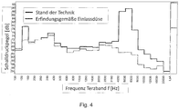
- This is also shown in the frequency third octave band representation Figure 4 the sound pressure level inlet nozzle 1 out Fig. 1 in which there is a significant reduction in the sound pressure level at frequency values of 125-160 and 4000-8000Hz.
Landscapes
- Engineering & Computer Science (AREA)
- Mechanical Engineering (AREA)
- General Engineering & Computer Science (AREA)
- Structures Of Non-Positive Displacement Pumps (AREA)
- Jet Pumps And Other Pumps (AREA)
Description
- Die Erfindung betrifft eine Einlaufdüse für einen Radialventilator.
- Gattungsgemäße Einlaufdüsen sind beispielsweise aus dem Stand der Technik
EP 1 122 444 B1 bekannt. Darin wird eine Einlaufdüse an einem Laufrad eines Radialventilators offenbart, das an seiner hinterschnittfrei ausgebildeten Wandung ein Störelement aufweist. Der Konstruktion liegt die Erkenntnis zugrunde, dass Schall durch lokale Druckschwankungen im Luftstrom entsteht, die ihrerseits auf Ablösungserscheinungen oder starke Geschwindigkeitsänderungen des Luftstromes zurückzuführen sind. Die durch das Störelement verbreiterte Grenzschicht an der Düsenwandung verursacht einen geringeren Geschwindigkeitsgradienten beim Ausgleich zwischen der aus der Einlaufdüse austretenden Luftströmung und dem im Spalt zwischen der Einlaufdüse und dem Laufrad austretenden Luftstrom. Der Geschwindigkeitsgradient hat einen direkten Einfluss auf die Schallleistung, da er proportional zu den Wechselwirkungskräften ist, die auf die Luftteilchen wirken. Diese Wechselwirkungskräfte auf die Luftteilchen sind wiederum proportional zur akustischen Leistung und somit zum Geräuschpegel. - Bekannt ist demgemäß, dass eine Störung der Strömung in der Einlaufdüse ihr Geräuschverhalten verbessert. Als Störkontur werden im Stand der Technik Sicken verwendet. Deren Einbringung in die Einlaufdüse ist vergleichsweise aufwendig, so dass der Bedarf nach einer fertigungstechnisch einfacheren Lösung bestand.
- Weiterer druckschriftlicher Stand der Technik ist in den Dokumenten
DE 10 2012 021 372 A1 ,US 2,083,186 A ,DE 33 04 963 A1 undDE 295 06 691 U1 offenbart. - Vor diesem Hintergrund liegt der Erfindung deshalb die Aufgabe zugrunde, eine Einlaufdüse bereit zu stellen, die einfach herstellbar ist und die bei geringem fertigungstechnischen Aufwand eine Geräuschentwicklung wirksam dämpft, ohne dass dabei nennenswerte Verluste bei der Luftleistung des angeschlossenen Ventilators auftreten.
- Diese Aufgabe wird durch die Merkmalskombination gemäß Patentanspruch 1 gelöst.
- Erfindungsgemäß wird eine Einlaufdüse für einen Radialventilator mit in Strömungsrichtung gesehen mehreren über die Wandung der Einlaufdüse bestimmten Strömungsabschnitten vorgeschlagen, umfassend einen eine Einlassöffnung aufweisenden Einlassabschnitt E, einen sich an den Einlassabschnitt unmittelbar anschließenden Störabschnitt S und einen sich unmittelbar an den Störabschnitt anschließenden Auslassabschnitt A. Der Strömungsquerschnitt der Einlaufdüse verringert sich im Einlassabschnitt. Der zwischen dem Einlassabschnitt und dem Auslassabschnitt ausgebildete Störabschnitt ist über seine gesamte axiale Länge zylinderförmig ausgebildet und erstreckt sich parallel zur Rotationsachse der Einlaufdüse, so dass der Strömungsquerschnitt der Einlaufdüse im Störabschnitt konstant ist.
- Alle in der vorliegenden Offenbarung genannten Strömungsabschnitte werden stets über die Form der zur Strömung gerichteten Innenwandung der Einlaufdüse bestimmt. Vorzugsweise ist die Einlaufdüse trichterförmig und rotationssymmetrisch um die Rotationsachse.
- Die Zylinderform der Wandung der Einlaufdüse im Störabschnitt ist im Vergleich zu dem Sicken des Stands der Technik einfacher fertigbar. Der Übergang zwischen dem sich in Strömungsrichtung verringernden Strömungsquerschnitt des Einlassabschnitts zu dem Störabschnitt und dessen Zylinderform erzeugen die das Geräusch reduzierende Störung der Strömung durch die Einlaufdüse. Erfindungsgemäß zeigte sich, dass bereits die Formgebung des sich an den sich verjüngenden Einlassabschnitt anschließenden Störabschnitts als zylindrisch ausreicht, um die Strömung ausreichend zu beeinflussen, um mindestens die im Stand der Technik über Sicken erreichte Störung zu gewährleisten.
- In einer Ausführungsform ist vorgesehen, dass von den Strömungsabschnitten ausschließlich der Störabschnitt zylinderförmig und sich parallel zur Rotationsachse der Einlaufdüse erstreckend ausgebildet ist. Das bedeutet, dass die die Einlaufdüse durchströmende Luftströmung nach Durchlaufen des Störabschnitts im Auslassabschnitt wieder eine Beeinflussung durch eine geänderte Form der Innenwandung erfährt. Vorteilhaft ist eine Ausbildung, bei der der Übergang von dem Einlassabschnitt zu dem Störabschnitt und von dem Störabschnitt zu dem Auslassabschnitt jeweils unstetig ist. Der unstetige Übergang erzeugt zwischen dem Einlassabschnitt, dem Störabschnitt und dem Auslassabschnitt eine erhöhte Turbulenz, wobei jedoch eine Ablösung der Grenzschicht gehemmt wird.
- Ferner ist erfindungsgemäß vorgesehen, dass sich der Strömungsquerschnitt der Einlaufdüse im Auslassabschnitt verringert, d.h. die Wandung des Auslassabschnitts zumindest abschnittsweise zur Rotationsachse hin verläuft. Günstig ist hierbei eine Ausführung, bei der der Auslassabschnitt über seine gesamte axiale Länge in Strömungsrichtung konvergent zur Rotationsachse der Einlaufdüse verläuft.
- Ferner ist eine Ausführung der Einlaufdüse vorteilhaft, bei der sich in Strömungsrichtung verjüngende Einlassabschnitt im Axialschnitt gesehen eine gerundete Kontur aufweist. Zudem weist der Einlassabschnitt günstigerweise in Strömungsrichtung gesehen einen stetigen Verlauf auf.
- In einer Weiterbildung der Einlaufdüse ist vorgesehen, dass der Auslassabschnitt in Strömungsrichtung mehrere, sich aneinander anschließende Subabschnitte aufweist, wobei zumindest einer der Subabschnitte im Axialschnitt gesehen eine gerundete Kontur aufweist. Beide Subabschnitte verlaufen jedoch vorteilhafterweise konvergent zur Rotationsachse.
- Ferner umfasst die Einlaufdüse erfindungsgemäß als weiteren Strömungsabschnitt den sich in Strömungsrichtung gesehen unmittelbar an den Auslassabschnitt anschließenden Austrittsabschnitt Z, der auch die Austrittsöffnung der Einlaufdüse bildet. Der Austrittsabschnitt, der vorteilhafterweise in Strömungsrichtung divergent zur Rotationsachse der Einlaufdüse verläuft, weist einen sich in Strömungsrichtung vergrößernden Strömungsquerschnitt auf (Diffusorform), so dass die Einlaufdüse über ihre Axialerstreckung eine Venturiform ausbildet.
- Ferner ist strömungstechnisch vorteilhaft, dass der Übergang von dem Auslassabschnitt zu dem Austrittsabschnitt einen stetigen Verlauf aufweist.
- Besonders günstige Ergebnisse werden bei der Einlaufdüse bezüglich des Geräuschverhaltens und bezüglich der Leistung des angeschlossenen Radialventilators erreicht, wenn das Größenverhältnis der axialen Einlasshöhe E des Einlassabschnitts gegenüber der axialen Gesamthöhe H der Einlaufdüse in einem Bereich von 0,15 ≤ E/H ≤ 0,30, weiter bevorzugt bei 0,2 - 0,25, weiter bevorzugt bei 0,22 festgelegt ist.
- Zusätzlich oder alternativ wirkt sich eine geometrische Ausbildung der Einlaufdüse vorteilhaft aus, bei der das Größenverhältnis der axialen Störhöhe S des Störabschnitts gegenüber der axialen Gesamthöhe H der Einlaufdüse in einem Bereich von 0,08 ≤ S/H ≤ 0,14, weiter bevorzugt bei 0,09 - 0,11, weiter bevorzugt bei 0,1 festgelegt ist.
- Ferner wirkt sich eine geometrische Ausbildung der Einlaufdüse vorteilhaft aus, bei der das Größenverhältnis der axialen Auslasshöhe A des Auslassabschnitts gegenüber der axialen Austrittshöhe Z des Austrittschnitts der Einlaufdüse in einem Bereich von 1,8 ≤ A/Z ≤ 2,8, weiter bevorzugt bei 2,2 - 2,4, weiter bevorzugt bei 2,30 festgelegt ist.
- Alle offenbarten Merkmale sind beliebig kombinierbar soweit dies technisch möglich ist und nicht im Widerspruch steht. Weitere vorteilhafte Weiterbildungen der Erfindung sind in den Unteransprüchen gekennzeichnet bzw. werden nachstehend zusammen mit der Beschreibung der bevorzugten Ausführung der Erfindung anhand der Figuren näher dargestellt. Es zeigen:
- Fig. 1
- einen Axialschnitt durch einen Abschnitt einer erfindungsgemäßen Einlaufdüse, angeordnet an einem Laufrad;
- Fig. 2
- ein Kurvendiagramm mit Ergebnissen der Einlaufdüse aus
Fig. 1 ; - Fig. 3
- eine Detailansicht der Schalleistung aus
Fig. 2 ; - Fig. 4
- eine Darstellung des Schalldruckpegels der Einlaufdüse aus
Fig. 1 . - In
Figur 1 ist ein Ausführungsbeispiel einer rotationssymmetrischen trichterförmigen Einlaufdüse 1, angeordnet an einem Laufrad 30, im Axialschnitt gezeigt, wobei lediglich die Details der Wandung zur Darstellung der Strömungsabschnitte wiedergegeben sind. Von dem Laufrad 30 ist im Wesentlichen die Deckscheibe 31 zu erkennen. - Als Strömungsabschnitte umfasst die Einlaufdüse 1 den die Einlassöffnung 7 bestimmenden Einlassabschnitt 2, den sich an den Einlassabschnitt 2 unmittelbar anschließenden Störabschnitt 3, den sich unmittelbar an den Störabschnitt 3 anschließenden Auslassabschnitt 4 sowie den sich unmittelbar an den Auslassabschnitt 4 anschließenden und die Auslassöffnung 8 bildenden Austrittsabschnitt 5. Der Einlassabschnitt 2 geht an seinem axialen Rand in einen Befestigungsflansch 6 über, dessen Form variabel rund oder eckig ausgebildet werden kann.
- Der Strömungsquerschnitt der Einlaufdüse 1 in den Strömungsabschnitten wird durch die geometrische Form der jeweiligen Wandung gewährleistet. In der gezeigten Ausführung entspricht die Außenwandform jeweils der Innenwandform, jedoch wird der Strömungsquerschnitt ausschließlich über die Innenwandform definiert. Im Einlassabschnitt 2 verringert sich der Strömungsquerschnitt, wobei die Wandung eine im Querschnitt gesehen elliptische Rundung RE aufweist. Der sich an den Einlassabschnitt 2 anschließende Störabschnitt 3 ist über seine gesamte axiale Länge umlaufend zylinderförmig und erstreckt sich parallel zur Rotationsachse der Einlaufdüse 1. Der Strömungsquerschnitt der Einlaufdüse 1 ist im Störabschnitt 3 konstant. Der sich an den Störabschnitt 3 anschließende Auslassabschnitt 4 weist, im Querschnitt gemäß
Figur 1 gesehen, ebenfalls eine den Strömungsquerschnitt verringernde Rundung RAL auf, die jedoch geringer ist als die Rundung RE des Einlassabschnitts 2. Der Auslassabschnitt 4 verläuft dabei konvergent zur Rotationsachse der Einlaufdüse 1. An den Auslassabschnitt 4 schließt sich mit einem stetigen Übergang der den Strömungsquerschnitt vergrößernde Austrittsabschnitt 5 mit einer nach radial außen gerichteteten Rundung RAT an, so dass die Einlaufdüse 1 insgesamt eine Venturiform aufweist. - Die Verläufe der einzelnen Strömungsabschnitte 2, 3, 4, 5 sind jeweils stetig, die Übergänge zwischen dem Einlassabschnitt 2 und dem Störabschnitt 3 sowie dem Störabschnitt 3 und dem Auslassabschnitt 4 sind hingegen unstetig.
- Bei der gezeigten Ausführungsvariante entspricht das Größenverhältnis der axialen Einlasshöhe E des Einlassabschnitts 2 gegenüber der axialen Gesamthöhe H der Einlaufdüse 1 einem Wert von 0,22. Das Größenverhältnis der axialen Störhöhe S des Störabschnitts 3 gegenüber der axialen Gesamthöhe H entspricht einem Wert von 0,10. Schließlich weist das Größenverhältnis der axialen Auslasshöhe A des Auslassabschnitts 4 gegenüber der axialen Austrittshöhe Z des Austrittschnitts 5 der Einlaufdüse 1 einen Wert von 2,30 auf.
- Die Einlaufdüse 1 gemäß
Figur 1 erzielt die in denFiguren 2 und3 anhand von Kurvendiagrammen dargestellten, gegenüber Einlaufdüsen des Stands der Technik ohne Störabschnitt verbesserten Geräuschwerte (Schallleistung) bei nicht nennenswert veränderten Werten des Drucks, der Drehzahl und der Leistung des angeschlossenen identischen Radialventilators. Die Werte des Stands der Technik sind stets mit Quadraten, diejenigen der Einlaufdüse 1 mit Punkten gekennzeichnet. Wie inFigur 3 zu erkennen, verbessert sich insbesondere bei hohen Volumenströmen das Geräuschverhalten, d.h. der Schallleistungspegel verringert sich. Dies wird ferner in der Frequenz-Terzband-Darstellung gemäßFigur 4 des Schalldruckpegels Einlaufdüse 1 ausFig. 1 ersichtlich, bei der sich eine deutliche Reduzierung des Schalldruckpegels bei Frequenzwerten von 125-160 und 4000-8000Hz einstellen.
Claims (10)
- Einlaufdüse für einen Radialventilator mit in Strömungsrichtung gesehen mehreren über die Wandung der Einlaufdüse (1) bestimmten Strömungsabschnitten, die zumindest umfassen: einen eine Einlassöffnung (7) aufweisenden Einlassabschnitt (2), einen sich an den Einlassabschnitt (2) unmittelbar anschließenden Störabschnitt (3) und einen sich unmittelbar an den Störabschnitt (3) anschließenden Auslassabschnitt, wobei sich ein Strömungsquerschnitt der Einlaufdüse (1) im Einlassabschnitt (2) verringert, wobei der zwischen dem Einlassabschnitt (2) und dem Auslassabschnitt (4) ausgebildete Störabschnitt (3) über seine gesamte axiale Länge zylinderförmig und sich parallel zur Rotationsachse der Einlaufdüse (1) erstreckend ausgebildet ist, so dass der Strömungsquerschnitt der Einlaufdüse (1) im Störabschnitt (3) konstant ist, dadurch gekennzeichnet, dass sich ein Strömungsquerschnitt der Einlaufdüse (1) im Auslassabschnitt (4) verringert, und wobei sich als weiterer Strömungsabschnitt, in Strömungsrichtung, gesehen an den Auslassabschnitt (4) unmittelbar ein eine Austrittsöffnung (8) bildender Austrittsabschnitt (5) anschließt, der in Strömungsrichtung divergent zur Rotationsachse der Einlaufdüse (1) verläuft und dessen Strömungsquerschnitt sich in Strömungsrichtung vergrößert.
- inlaufdüse nach Anspruch 1 dadurch gekennzeichnet, dass der sich in Strömungsrichtung verjüngende Einlassabschnitt (2) im Axialschnitt gesehen eine gerundete Kontur aufweist.
- Einlaufdüse nach einem der vorigen Ansprüche, dadurch gekennzeichnet, dass der Einlassabschnitt (2) in Strömungsrichtung gesehen einen stetigen Verlauf aufweist.
- Einlaufdüse nach einem der vorigen Ansprüche, dadurch gekennzeichnet, dass ein Übergang von dem Einlassabschnitt (2) zu dem Störabschnitt (3) und von dem Störabschnitt (3) zu dem Auslassabschnitt (4) jeweils unstetig ist.
- Einlaufdüse nach einem der vorigen Ansprüche, dadurch gekennzeichnet, dass der Auslassabschnitt (4) in Strömungsrichtung konvergent zur Rotationsachse der Einlaufdüse (1) verläuft.
- Einlaufdüse nach einem der vorigen Ansprüche, dadurch gekennzeichnet, dass der Auslassabschnitt (4) in Strömungsrichtung mehrere, sich in Strömungsrichtung aneinander anschließende Subabschnitte aufweist, wobei zumindest einer der Subabschnitte im Axialschnitt gesehen eine gerundete Kontur aufweist.
- Einlaufdüse nach Anspruch 1, dadurch gekennzeichnet, dass ein Übergang von dem Auslassabschnitt (4) zu dem Austrittsabschnitt (5) einen stetigen Verlauf aufweist.
- Einlaufdüse nach einem der vorigen Ansprüche, dadurch gekennzeichnet, dass ein Größenverhältnis einer axialen Einlasshöhe E des Einlassabschnitts (2) gegenüber einer axialen Gesamthöhe H der Einlaufdüse (1) so festgelegt ist, dass gilt 0,15 ≤ E/H ≤ 0,30.
- Einlaufdüse nach einem der vorigen Ansprüche, dadurch gekennzeichnet, dass ein Größenverhältnis einer axialen Störhöhe S des Störabschnitts (3) gegenüber einer axialen Gesamthöhe H der Einlaufdüse (1) so festgelegt ist, dass gilt 0,08 ≤S/H ≤ 0,14.
- Einlaufdüse nach einem der vorigen Ansprüche, dadurch gekennzeichnet, dass ein Größenverhältnis einer axialen Auslasshöhe A des Auslassabschnitts (4) gegenüber einer axialen Austrittshöhe Z des Austrittschnitts (5) der Einlaufdüse (1) so estgelegt ist, dass gilt 1,8 ≤ A/Z ≤ 2,8.
Applications Claiming Priority (1)
| Application Number | Priority Date | Filing Date | Title |
|---|---|---|---|
| DE102016118856.5A DE102016118856A1 (de) | 2016-10-05 | 2016-10-05 | Einlaufdüse für einen Radialventilator |
Publications (2)
| Publication Number | Publication Date |
|---|---|
| EP3306100A1 EP3306100A1 (de) | 2018-04-11 |
| EP3306100B1 true EP3306100B1 (de) | 2021-07-21 |
Family
ID=59000249
Family Applications (1)
| Application Number | Title | Priority Date | Filing Date |
|---|---|---|---|
| EP17188456.2A Active EP3306100B1 (de) | 2016-10-05 | 2017-08-30 | Einlaufdüse für einen radialventilator |
Country Status (4)
| Country | Link |
|---|---|
| US (1) | US10612561B2 (de) |
| EP (1) | EP3306100B1 (de) |
| CN (1) | CN206246418U (de) |
| DE (1) | DE102016118856A1 (de) |
Families Citing this family (1)
| Publication number | Priority date | Publication date | Assignee | Title |
|---|---|---|---|---|
| WO2020115540A1 (en) * | 2018-12-07 | 2020-06-11 | Regal Beloit America, Inc. | A centrifugal blower assembly |
Family Cites Families (8)
| Publication number | Priority date | Publication date | Assignee | Title |
|---|---|---|---|---|
| US2083186A (en) * | 1936-03-23 | 1937-06-08 | American Blower Corp | Fan |
| DE3304963A1 (de) * | 1983-02-12 | 1984-08-16 | Hans Joachim 7440 Nürtingen Leithner | Radailventilator fuer lueftungstechnische anlagen |
| DE4222131C3 (de) * | 1992-07-06 | 2000-01-27 | Vem Motors Gmbh | Belüftungseinrichtung für die Druckbelüftung von oberflächenbelüfteten elektrischen Maschinen |
| DE29506691U1 (de) * | 1995-04-20 | 1996-08-29 | Papst-Motoren GmbH & Co KG, 78112 St Georgen | Brennergebläse mit Radiallaufrad |
| DE20001746U1 (de) * | 2000-02-01 | 2001-06-21 | ebm Werke GmbH & Co., 74673 Mulfingen | Radialventilator und Düse für einen Radialventilator |
| US6499948B1 (en) * | 2000-02-07 | 2002-12-31 | Penn Ventilation, Inc. | Shroud and axial fan therefor |
| DE102012021372B4 (de) * | 2012-10-25 | 2023-05-04 | Ziehl-Abegg Se | Einlaufdüse für Radialventilatoren sowie Radialventilator |
| DE102015207948A1 (de) * | 2015-04-29 | 2016-11-03 | Ziehl-Abegg Se | Einströmdüse für einen Radial-, Diagonal- oder Axialventilator und Radial-, Diagonal- oder Axialventilator mit einer Einströmdüse |
-
2016
- 2016-10-05 DE DE102016118856.5A patent/DE102016118856A1/de not_active Withdrawn
- 2016-11-17 CN CN201621233817.4U patent/CN206246418U/zh active Active
-
2017
- 2017-08-30 EP EP17188456.2A patent/EP3306100B1/de active Active
- 2017-09-15 US US15/705,630 patent/US10612561B2/en active Active
Also Published As
| Publication number | Publication date |
|---|---|
| EP3306100A1 (de) | 2018-04-11 |
| DE102016118856A1 (de) | 2018-04-05 |
| CN206246418U (zh) | 2017-06-13 |
| US20180094641A1 (en) | 2018-04-05 |
| US10612561B2 (en) | 2020-04-07 |
Similar Documents
| Publication | Publication Date | Title |
|---|---|---|
| EP2696029B1 (de) | Schaufelgitter mit Seitenwandkonturierung und Strömungsmaschine | |
| EP3298284B1 (de) | Ebenes strömungsleitgitter | |
| DE102004022063A1 (de) | Abgasdiffusor für eine Axialströmungsturbine | |
| EP3702620B1 (de) | Axialventilator mit geräuschreduzierenden lüfterradschaufeln, die bohrungen aufweisen | |
| DE202015104813U1 (de) | Strömungsleitgitter zur Anordnung an einem Ventilator | |
| EP3527832B1 (de) | Spiralgehäuse eines radialventilators | |
| EP3705727B1 (de) | Lüfterrad eines axialventilators | |
| DE102013114609A1 (de) | Radial-Laufrad für einen Trommellüfter und Lüftereinheit mit einem derartigen Radial-Laufrad | |
| EP3225781B1 (de) | Schaufelkanal, schaufelgitter und strömungsmaschine | |
| EP2356320A1 (de) | Ringdiffusor für eine axialturbomaschine | |
| EP3372838B1 (de) | Raumlufttechnische lüftungsanlage mit einer luftleitanordnung | |
| DE102018211808A1 (de) | Ventilator und Leiteinrichtung für einen Ventilator | |
| DE102015111746A1 (de) | Gekühltes Turbinenlaufrad, insbesondere für ein Flugtriebwerk | |
| WO2016173595A1 (de) | Einströmdüse für einen radial-, diagonal- oder axialventilator und radial-, diagonal- oder axialventilator mit einer einströmdüse | |
| DE112009001754T5 (de) | Abgasdiffusor für Gasturbine | |
| EP3724511B1 (de) | Diagonalventilatorrad mit erhöhter festigkeit | |
| DE102012021372A1 (de) | Einlaufdüse für Radialventilatoren sowie Radialventilator | |
| EP3312427B2 (de) | Ventilator mit ventilatorrad und leitrad | |
| DE102010020379A1 (de) | Einstellbarer Radialverdichterdiffusor | |
| DE102014115286A1 (de) | Abzugsvorrichtung, insbesondere Dunstabzugsvorrichtung | |
| EP3306100A1 (de) | Einlaufdüse für einen radialventilator | |
| DE202016105522U1 (de) | Einlaufdüse für einen Radialventilator | |
| EP1122444B1 (de) | Radialventilator und Düse für einen Radialventilator | |
| EP3833873A1 (de) | Luftleitanordnung für eine lüftungsanlage | |
| DE102011107523B4 (de) | System zum Einblasen eines Fluids, Verdichter sowie Turbomaschine |
Legal Events
| Date | Code | Title | Description |
|---|---|---|---|
| PUAI | Public reference made under article 153(3) epc to a published international application that has entered the european phase |
Free format text: ORIGINAL CODE: 0009012 |
|
| STAA | Information on the status of an ep patent application or granted ep patent |
Free format text: STATUS: THE APPLICATION HAS BEEN PUBLISHED |
|
| AK | Designated contracting states |
Kind code of ref document: A1 Designated state(s): AL AT BE BG CH CY CZ DE DK EE ES FI FR GB GR HR HU IE IS IT LI LT LU LV MC MK MT NL NO PL PT RO RS SE SI SK SM TR |
|
| AX | Request for extension of the european patent |
Extension state: BA ME |
|
| STAA | Information on the status of an ep patent application or granted ep patent |
Free format text: STATUS: REQUEST FOR EXAMINATION WAS MADE |
|
| 17P | Request for examination filed |
Effective date: 20180710 |
|
| RBV | Designated contracting states (corrected) |
Designated state(s): AL AT BE BG CH CY CZ DE DK EE ES FI FR GB GR HR HU IE IS IT LI LT LU LV MC MK MT NL NO PL PT RO RS SE SI SK SM TR |
|
| GRAP | Despatch of communication of intention to grant a patent |
Free format text: ORIGINAL CODE: EPIDOSNIGR1 |
|
| STAA | Information on the status of an ep patent application or granted ep patent |
Free format text: STATUS: GRANT OF PATENT IS INTENDED |
|
| RIC1 | Information provided on ipc code assigned before grant |
Ipc: F04D 17/16 20060101AFI20210215BHEP Ipc: F04D 29/66 20060101ALI20210215BHEP Ipc: F04D 29/42 20060101ALI20210215BHEP |
|
| INTG | Intention to grant announced |
Effective date: 20210312 |
|
| GRAS | Grant fee paid |
Free format text: ORIGINAL CODE: EPIDOSNIGR3 |
|
| GRAA | (expected) grant |
Free format text: ORIGINAL CODE: 0009210 |
|
| STAA | Information on the status of an ep patent application or granted ep patent |
Free format text: STATUS: THE PATENT HAS BEEN GRANTED |
|
| AK | Designated contracting states |
Kind code of ref document: B1 Designated state(s): AL AT BE BG CH CY CZ DE DK EE ES FI FR GB GR HR HU IE IS IT LI LT LU LV MC MK MT NL NO PL PT RO RS SE SI SK SM TR |
|
| REG | Reference to a national code |
Ref country code: GB Ref legal event code: FG4D Free format text: NOT ENGLISH |
|
| REG | Reference to a national code |
Ref country code: CH Ref legal event code: EP |
|
| REG | Reference to a national code |
Ref country code: DE Ref legal event code: R096 Ref document number: 502017010946 Country of ref document: DE |
|
| REG | Reference to a national code |
Ref country code: AT Ref legal event code: REF Ref document number: 1412834 Country of ref document: AT Kind code of ref document: T Effective date: 20210815 |
|
| REG | Reference to a national code |
Ref country code: IE Ref legal event code: FG4D Free format text: LANGUAGE OF EP DOCUMENT: GERMAN |
|
| REG | Reference to a national code |
Ref country code: NL Ref legal event code: FP |
|
| REG | Reference to a national code |
Ref country code: LT Ref legal event code: MG9D |
|
| PG25 | Lapsed in a contracting state [announced via postgrant information from national office to epo] |
Ref country code: SE Free format text: LAPSE BECAUSE OF FAILURE TO SUBMIT A TRANSLATION OF THE DESCRIPTION OR TO PAY THE FEE WITHIN THE PRESCRIBED TIME-LIMIT Effective date: 20210721 Ref country code: RS Free format text: LAPSE BECAUSE OF FAILURE TO SUBMIT A TRANSLATION OF THE DESCRIPTION OR TO PAY THE FEE WITHIN THE PRESCRIBED TIME-LIMIT Effective date: 20210721 Ref country code: LT Free format text: LAPSE BECAUSE OF FAILURE TO SUBMIT A TRANSLATION OF THE DESCRIPTION OR TO PAY THE FEE WITHIN THE PRESCRIBED TIME-LIMIT Effective date: 20210721 Ref country code: BG Free format text: LAPSE BECAUSE OF FAILURE TO SUBMIT A TRANSLATION OF THE DESCRIPTION OR TO PAY THE FEE WITHIN THE PRESCRIBED TIME-LIMIT Effective date: 20211021 Ref country code: NO Free format text: LAPSE BECAUSE OF FAILURE TO SUBMIT A TRANSLATION OF THE DESCRIPTION OR TO PAY THE FEE WITHIN THE PRESCRIBED TIME-LIMIT Effective date: 20211021 Ref country code: PT Free format text: LAPSE BECAUSE OF FAILURE TO SUBMIT A TRANSLATION OF THE DESCRIPTION OR TO PAY THE FEE WITHIN THE PRESCRIBED TIME-LIMIT Effective date: 20211122 Ref country code: HR Free format text: LAPSE BECAUSE OF FAILURE TO SUBMIT A TRANSLATION OF THE DESCRIPTION OR TO PAY THE FEE WITHIN THE PRESCRIBED TIME-LIMIT Effective date: 20210721 Ref country code: ES Free format text: LAPSE BECAUSE OF FAILURE TO SUBMIT A TRANSLATION OF THE DESCRIPTION OR TO PAY THE FEE WITHIN THE PRESCRIBED TIME-LIMIT Effective date: 20210721 Ref country code: FI Free format text: LAPSE BECAUSE OF FAILURE TO SUBMIT A TRANSLATION OF THE DESCRIPTION OR TO PAY THE FEE WITHIN THE PRESCRIBED TIME-LIMIT Effective date: 20210721 |
|
| PG25 | Lapsed in a contracting state [announced via postgrant information from national office to epo] |
Ref country code: PL Free format text: LAPSE BECAUSE OF FAILURE TO SUBMIT A TRANSLATION OF THE DESCRIPTION OR TO PAY THE FEE WITHIN THE PRESCRIBED TIME-LIMIT Effective date: 20210721 Ref country code: LV Free format text: LAPSE BECAUSE OF FAILURE TO SUBMIT A TRANSLATION OF THE DESCRIPTION OR TO PAY THE FEE WITHIN THE PRESCRIBED TIME-LIMIT Effective date: 20210721 Ref country code: GR Free format text: LAPSE BECAUSE OF FAILURE TO SUBMIT A TRANSLATION OF THE DESCRIPTION OR TO PAY THE FEE WITHIN THE PRESCRIBED TIME-LIMIT Effective date: 20211022 |
|
| REG | Reference to a national code |
Ref country code: CH Ref legal event code: PL |
|
| REG | Reference to a national code |
Ref country code: DE Ref legal event code: R097 Ref document number: 502017010946 Country of ref document: DE Ref country code: BE Ref legal event code: MM Effective date: 20210831 |
|
| PG25 | Lapsed in a contracting state [announced via postgrant information from national office to epo] |
Ref country code: LI Free format text: LAPSE BECAUSE OF NON-PAYMENT OF DUE FEES Effective date: 20210831 Ref country code: DK Free format text: LAPSE BECAUSE OF FAILURE TO SUBMIT A TRANSLATION OF THE DESCRIPTION OR TO PAY THE FEE WITHIN THE PRESCRIBED TIME-LIMIT Effective date: 20210721 Ref country code: CH Free format text: LAPSE BECAUSE OF NON-PAYMENT OF DUE FEES Effective date: 20210831 |
|
| PLBE | No opposition filed within time limit |
Free format text: ORIGINAL CODE: 0009261 |
|
| STAA | Information on the status of an ep patent application or granted ep patent |
Free format text: STATUS: NO OPPOSITION FILED WITHIN TIME LIMIT |
|
| PG25 | Lapsed in a contracting state [announced via postgrant information from national office to epo] |
Ref country code: SM Free format text: LAPSE BECAUSE OF FAILURE TO SUBMIT A TRANSLATION OF THE DESCRIPTION OR TO PAY THE FEE WITHIN THE PRESCRIBED TIME-LIMIT Effective date: 20210721 Ref country code: SK Free format text: LAPSE BECAUSE OF FAILURE TO SUBMIT A TRANSLATION OF THE DESCRIPTION OR TO PAY THE FEE WITHIN THE PRESCRIBED TIME-LIMIT Effective date: 20210721 Ref country code: RO Free format text: LAPSE BECAUSE OF FAILURE TO SUBMIT A TRANSLATION OF THE DESCRIPTION OR TO PAY THE FEE WITHIN THE PRESCRIBED TIME-LIMIT Effective date: 20210721 Ref country code: MC Free format text: LAPSE BECAUSE OF FAILURE TO SUBMIT A TRANSLATION OF THE DESCRIPTION OR TO PAY THE FEE WITHIN THE PRESCRIBED TIME-LIMIT Effective date: 20210721 Ref country code: LU Free format text: LAPSE BECAUSE OF NON-PAYMENT OF DUE FEES Effective date: 20210830 Ref country code: EE Free format text: LAPSE BECAUSE OF FAILURE TO SUBMIT A TRANSLATION OF THE DESCRIPTION OR TO PAY THE FEE WITHIN THE PRESCRIBED TIME-LIMIT Effective date: 20210721 Ref country code: CZ Free format text: LAPSE BECAUSE OF FAILURE TO SUBMIT A TRANSLATION OF THE DESCRIPTION OR TO PAY THE FEE WITHIN THE PRESCRIBED TIME-LIMIT Effective date: 20210721 Ref country code: AL Free format text: LAPSE BECAUSE OF FAILURE TO SUBMIT A TRANSLATION OF THE DESCRIPTION OR TO PAY THE FEE WITHIN THE PRESCRIBED TIME-LIMIT Effective date: 20210721 |
|
| 26N | No opposition filed |
Effective date: 20220422 |
|
| PG25 | Lapsed in a contracting state [announced via postgrant information from national office to epo] |
Ref country code: IE Free format text: LAPSE BECAUSE OF NON-PAYMENT OF DUE FEES Effective date: 20210830 Ref country code: BE Free format text: LAPSE BECAUSE OF NON-PAYMENT OF DUE FEES Effective date: 20210831 |
|
| PG25 | Lapsed in a contracting state [announced via postgrant information from national office to epo] |
Ref country code: HU Free format text: LAPSE BECAUSE OF FAILURE TO SUBMIT A TRANSLATION OF THE DESCRIPTION OR TO PAY THE FEE WITHIN THE PRESCRIBED TIME-LIMIT; INVALID AB INITIO Effective date: 20170830 |
|
| P01 | Opt-out of the competence of the unified patent court (upc) registered |
Effective date: 20230522 |
|
| PG25 | Lapsed in a contracting state [announced via postgrant information from national office to epo] |
Ref country code: CY Free format text: LAPSE BECAUSE OF FAILURE TO SUBMIT A TRANSLATION OF THE DESCRIPTION OR TO PAY THE FEE WITHIN THE PRESCRIBED TIME-LIMIT Effective date: 20210721 |
|
| PG25 | Lapsed in a contracting state [announced via postgrant information from national office to epo] |
Ref country code: MK Free format text: LAPSE BECAUSE OF FAILURE TO SUBMIT A TRANSLATION OF THE DESCRIPTION OR TO PAY THE FEE WITHIN THE PRESCRIBED TIME-LIMIT Effective date: 20210721 |
|
| PG25 | Lapsed in a contracting state [announced via postgrant information from national office to epo] |
Ref country code: TR Free format text: LAPSE BECAUSE OF FAILURE TO SUBMIT A TRANSLATION OF THE DESCRIPTION OR TO PAY THE FEE WITHIN THE PRESCRIBED TIME-LIMIT Effective date: 20210721 |
|
| PGFP | Annual fee paid to national office [announced via postgrant information from national office to epo] |
Ref country code: NL Payment date: 20240821 Year of fee payment: 8 |
|
| PG25 | Lapsed in a contracting state [announced via postgrant information from national office to epo] |
Ref country code: MT Free format text: LAPSE BECAUSE OF FAILURE TO SUBMIT A TRANSLATION OF THE DESCRIPTION OR TO PAY THE FEE WITHIN THE PRESCRIBED TIME-LIMIT Effective date: 20210721 |
|
| PGFP | Annual fee paid to national office [announced via postgrant information from national office to epo] |
Ref country code: DE Payment date: 20240819 Year of fee payment: 8 |
|
| PGFP | Annual fee paid to national office [announced via postgrant information from national office to epo] |
Ref country code: GB Payment date: 20240822 Year of fee payment: 8 |
|
| PGFP | Annual fee paid to national office [announced via postgrant information from national office to epo] |
Ref country code: FR Payment date: 20240814 Year of fee payment: 8 |
|
| PGFP | Annual fee paid to national office [announced via postgrant information from national office to epo] |
Ref country code: AT Payment date: 20240819 Year of fee payment: 8 |
|
| PGFP | Annual fee paid to national office [announced via postgrant information from national office to epo] |
Ref country code: IT Payment date: 20240830 Year of fee payment: 8 |
|
| REG | Reference to a national code |
Ref country code: DE Ref legal event code: R119 Ref document number: 502017010946 Country of ref document: DE |
|
| REG | Reference to a national code |
Ref country code: NL Ref legal event code: MM Effective date: 20250901 |
|
| PG25 | Lapsed in a contracting state [announced via postgrant information from national office to epo] |
Ref country code: AT Free format text: LAPSE BECAUSE OF NON-PAYMENT OF DUE FEES Effective date: 20250830 |
|
| REG | Reference to a national code |
Ref country code: AT Ref legal event code: MM01 Ref document number: 1412834 Country of ref document: AT Kind code of ref document: T Effective date: 20250830 |
|
| GBPC | Gb: european patent ceased through non-payment of renewal fee |
Effective date: 20250830 |