EP3306092A1 - Piston pump having push rod assembly and stopping assembly - Google Patents
Piston pump having push rod assembly and stopping assembly Download PDFInfo
- Publication number
- EP3306092A1 EP3306092A1 EP17193080.3A EP17193080A EP3306092A1 EP 3306092 A1 EP3306092 A1 EP 3306092A1 EP 17193080 A EP17193080 A EP 17193080A EP 3306092 A1 EP3306092 A1 EP 3306092A1
- Authority
- EP
- European Patent Office
- Prior art keywords
- push rod
- assembly
- rod assembly
- piston pump
- towards
- Prior art date
- Legal status (The legal status is an assumption and is not a legal conclusion. Google has not performed a legal analysis and makes no representation as to the accuracy of the status listed.)
- Granted
Links
Images






Classifications
-
- F—MECHANICAL ENGINEERING; LIGHTING; HEATING; WEAPONS; BLASTING
- F04—POSITIVE - DISPLACEMENT MACHINES FOR LIQUIDS; PUMPS FOR LIQUIDS OR ELASTIC FLUIDS
- F04B—POSITIVE-DISPLACEMENT MACHINES FOR LIQUIDS; PUMPS
- F04B53/00—Component parts, details or accessories not provided for in, or of interest apart from, groups F04B1/00 - F04B23/00 or F04B39/00 - F04B47/00
- F04B53/14—Pistons, piston-rods or piston-rod connections
-
- F—MECHANICAL ENGINEERING; LIGHTING; HEATING; WEAPONS; BLASTING
- F02—COMBUSTION ENGINES; HOT-GAS OR COMBUSTION-PRODUCT ENGINE PLANTS
- F02M—SUPPLYING COMBUSTION ENGINES IN GENERAL WITH COMBUSTIBLE MIXTURES OR CONSTITUENTS THEREOF
- F02M59/00—Pumps specially adapted for fuel-injection and not provided for in groups F02M39/00 -F02M57/00, e.g. rotary cylinder-block type of pumps
- F02M59/44—Details, components parts, or accessories not provided for in, or of interest apart from, the apparatus of groups F02M59/02 - F02M59/42; Pumps having transducers, e.g. to measure displacement of pump rack or piston
-
- F—MECHANICAL ENGINEERING; LIGHTING; HEATING; WEAPONS; BLASTING
- F04—POSITIVE - DISPLACEMENT MACHINES FOR LIQUIDS; PUMPS FOR LIQUIDS OR ELASTIC FLUIDS
- F04B—POSITIVE-DISPLACEMENT MACHINES FOR LIQUIDS; PUMPS
- F04B53/00—Component parts, details or accessories not provided for in, or of interest apart from, groups F04B1/00 - F04B23/00 or F04B39/00 - F04B47/00
- F04B53/14—Pistons, piston-rods or piston-rod connections
- F04B53/144—Adaptation of piston-rods
-
- F—MECHANICAL ENGINEERING; LIGHTING; HEATING; WEAPONS; BLASTING
- F02—COMBUSTION ENGINES; HOT-GAS OR COMBUSTION-PRODUCT ENGINE PLANTS
- F02M—SUPPLYING COMBUSTION ENGINES IN GENERAL WITH COMBUSTIBLE MIXTURES OR CONSTITUENTS THEREOF
- F02M59/00—Pumps specially adapted for fuel-injection and not provided for in groups F02M39/00 -F02M57/00, e.g. rotary cylinder-block type of pumps
- F02M59/02—Pumps specially adapted for fuel-injection and not provided for in groups F02M39/00 -F02M57/00, e.g. rotary cylinder-block type of pumps of reciprocating-piston or reciprocating-cylinder type
- F02M59/025—Pumps specially adapted for fuel-injection and not provided for in groups F02M39/00 -F02M57/00, e.g. rotary cylinder-block type of pumps of reciprocating-piston or reciprocating-cylinder type characterised by a single piston
-
- F—MECHANICAL ENGINEERING; LIGHTING; HEATING; WEAPONS; BLASTING
- F02—COMBUSTION ENGINES; HOT-GAS OR COMBUSTION-PRODUCT ENGINE PLANTS
- F02M—SUPPLYING COMBUSTION ENGINES IN GENERAL WITH COMBUSTIBLE MIXTURES OR CONSTITUENTS THEREOF
- F02M59/00—Pumps specially adapted for fuel-injection and not provided for in groups F02M39/00 -F02M57/00, e.g. rotary cylinder-block type of pumps
- F02M59/02—Pumps specially adapted for fuel-injection and not provided for in groups F02M39/00 -F02M57/00, e.g. rotary cylinder-block type of pumps of reciprocating-piston or reciprocating-cylinder type
- F02M59/10—Pumps specially adapted for fuel-injection and not provided for in groups F02M39/00 -F02M57/00, e.g. rotary cylinder-block type of pumps of reciprocating-piston or reciprocating-cylinder type characterised by the piston-drive
- F02M59/102—Mechanical drive, e.g. tappets or cams
-
- F—MECHANICAL ENGINEERING; LIGHTING; HEATING; WEAPONS; BLASTING
- F02—COMBUSTION ENGINES; HOT-GAS OR COMBUSTION-PRODUCT ENGINE PLANTS
- F02M—SUPPLYING COMBUSTION ENGINES IN GENERAL WITH COMBUSTIBLE MIXTURES OR CONSTITUENTS THEREOF
- F02M59/00—Pumps specially adapted for fuel-injection and not provided for in groups F02M39/00 -F02M57/00, e.g. rotary cylinder-block type of pumps
- F02M59/02—Pumps specially adapted for fuel-injection and not provided for in groups F02M39/00 -F02M57/00, e.g. rotary cylinder-block type of pumps of reciprocating-piston or reciprocating-cylinder type
-
- F—MECHANICAL ENGINEERING; LIGHTING; HEATING; WEAPONS; BLASTING
- F04—POSITIVE - DISPLACEMENT MACHINES FOR LIQUIDS; PUMPS FOR LIQUIDS OR ELASTIC FLUIDS
- F04B—POSITIVE-DISPLACEMENT MACHINES FOR LIQUIDS; PUMPS
- F04B53/00—Component parts, details or accessories not provided for in, or of interest apart from, groups F04B1/00 - F04B23/00 or F04B39/00 - F04B47/00
- F04B53/16—Casings; Cylinders; Cylinder liners or heads; Fluid connections
Definitions
- the present disclosure relates to piston pumps, and more particularly relates to a push rod assembly, a stopping assembly, and a piston pump having the push rod assembly and the stopping assembly.
- the piston pump may feed fuel from a reservoir to a fuel injection valve.
- the piston pump usually includes a push rod adapted to make a reciprocating movement within a chamber, a stopper for concentrically receiving the push rod, and a sealing ring disposed between the push rod and the stopper.
- the stopper is also utilized for limiting a downward movement of the push rod.
- the stopper may be disposed at a bottom of a housing of the piston pump, and may limit the downward movement of the push rod, when a bottom surface of the push rod comes into contact with a top surface of the stopper.
- the fuel is usually accumulated in the chamber, and is moved by the reciprocating movement of the push rod.
- the fuel available in the chamber gets pressurized between the push rod and the stopper.
- pressure surges are created in the fuel flowing towards the sealing ring hampering the operation of the sealing ring.
- sealing rings are not manufactured to withstand such pressure surges of the fuel.
- the sealing rings fail and have to be frequently replaced. This would lead to inconvenience and expenses with regard to replacement and maintenance of the sealing ring.
- the fuel may get mixed with lubrication oil resulting into a dilution of the lubrication oil.
- the lubrication oil may also have to be replaced once the dilution makes the lubrication oil unusable, for example, due to decrease in viscosity.
- the maintenance of the sealing ring and the lubrication oil may lead to a significant machine downtime and affect an overall performance of an engine.
- a stopping assembly of a piston pump includes a base portion having an inner surface for movably receiving a push rod assembly of the piston pump and an outer surface opposite to the inner surface engaged with a housing of the piston pump.
- the stopping assembly also includes a plurality of protruded structures adjacently disposed on the base portion forming a plurality of grooves. The plurality of grooves extends from the inner surface towards the outer surface to allow fluid to flow towards the outer surface.
- a push rod assembly of a piston pump in another aspect of the present disclosure, includes a rod coupled to a piston of the piston pump.
- the rod is adapted to perform a reciprocating movement within a housing of the piston pump.
- the push rod assembly includes a stopper portion having an inner surface fixedly engaged with the rod and an outer surface opposite to the inner surface.
- the push rod assembly further includes a plurality of protruded structures adjacently disposed on a first surface of the stopper portion forming a plurality of grooves extending from the inner surface towards the outer surface to allow fluid to flow towards the outer surface.
- a piston pump in yet another aspect of the present disclosure, includes a housing, a piston movably disposed in the housing, and a push rod assembly coupled to the piston.
- the push rod assembly is adapted to perform a reciprocating movement within the housing along with the piston.
- the push rod assembly includes a rod portion and a stopper portion.
- the stopper portion has an inner surface fixedly engaged with the rod portion and an outer surface opposite to the inner surface.
- the piston pump includes a stopping assembly for limiting a movement of the push rod assembly within the piston pump.
- the stopping assembly includes a base portion having an inner surface for movably receiving the push rod assembly and an outer surface opposite to the inner surface engaged with the housing.
- the piston pump further includes a plurality of protruded structures adjacently disposed on at least one of a first surface of the stopper portion and a first surface of the base portion.
- the plurality of protruded structures forms a plurality of grooves extending outwardly from the inner surface of one of the stopper portion and the base portion.
- FIG. 1 is a block diagram of an internal combustion engine 100 with a piston pump 102, according to one embodiment of the present disclosure.
- the piston pump 102 may be employed as a high-pressure fuel pump in a machine (not shown) having the internal combustion engine 100.
- the piston pump 102 may be employed in other systems of the machine, such as in a braking system (not shown), without departing from the scope of the present disclosure.
- the internal combustion engine 100 is interchangeably referred to as engine 100.
- the machine may include a fuel supply system 104 for supplying fuel to the engine 100.
- the fuel supply system 104 may be a pump-line nozzle system.
- the fuel supply system 104 may include, but is not limited to, a fuel reservoir 106, the piston pump 102, a fuel injection nozzle 110, and an Electronic Control Unit (ECU) 112.
- the fuel supply system 104 may further include a first conduit 114 for connecting the fuel reservoir 106 with the piston pump 102, and a second conduit 116 for connecting the piston pump 102 with the fuel injection nozzle 110. Therefore, the fuel reservoir 106, the first conduit 114, the piston pump 102, the second conduit 116, and the fuel injection nozzle 110 are fluidly coupled with each other.
- the ECU 112 may be in communication with the piston pump 102, the fuel injection nozzle 110, and the engine 100.
- the fuel to be delivered to the engine 100 may be stored in the fuel reservoir 106.
- the fuel may be delivered from the fuel reservoir 106 to the piston pump 102 through the first conduit 114.
- the fuel supply system 104 may include a supply pump (not shown) for pumping the fluid from the fuel reservoir 106 towards the piston pump 102.
- the piston pump 102 may pressurize the fuel, and may then supply the pressurized fuel to the fuel injection nozzle 110 through the second conduit 116.
- the operational and constructional features of the piston pump 102 are explained in detail in the description of FIG. 2 .
- the fuel injection nozzle 110 may be disposed in a cylinder head (not shown) of a cylinder (not shown) of the engine 100.
- the fuel injection nozzle 110 may be adapted to inject the fuel received from the piston pump 102 into the cylinder.
- the fuel injection nozzle 110 may include a needle valve (not shown) for controlling a flow of the fuel towards the cylinder. In an open state, the needle valve of the fuel injection nozzle 110 may allow the fuel from the second conduit 116 to flow towards the cylinder of the engine 100. In a closed state, the needle valve of the fuel injection nozzle 110 may block the flow of the fuel from the second conduit 116 towards the cylinder.
- the ECU 112 may control the opening and closing of the needle valve of the fuel injection nozzle 110 for selectively allowing the fuel to enter the cylinder of the engine 100 through the fuel injection nozzle 110.
- the engine 100 may include multiple cylinders.
- the fuel supply system 104 may include one fuel injection nozzle 110.
- the fuel supply system 104 may include one piston pump 102 for each fuel injection nozzle 110. Therefore, in one embodiment with multiple fuel injection nozzles 110, the fuel supply system 104 may include multiple piston pumps 102.
- the present disclosure is explained with regard to one piston pump 102 for one fuel injection nozzle 110, the present disclosure is equally applicable for the multiple piston pumps 102 supplying the fuel to the multiple fuel injection nozzles 110.
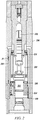
- FIG. 2 illustrates a cross-sectional view of the piston pump 102 having a push rod assembly 202 and a stopping assembly 204, according to one embodiment of the present disclosure.
- the piston pump 102 may include a housing 206, a piston 208 movably disposed within the housing 206, the push rod assembly 202 coupled to the piston 208, and the stopping assembly 204 disposed at or near a bottom 210 of the housing 206.
- the fuel from the second conduit 116 may enter the housing 206 through the fuel injection nozzle 110, and may lubricate the piston 208.
- the piston 208 may be coupled to the push rod assembly 202 which may in turn be coupled to an external push rod assembly (not shown).
- the external push rod assembly may enable the push rod assembly 202 to perform a reciprocating movement within the housing 206.
- the piston 208 since the piston 208 is coupled to the push rod assembly 202, the piston 208 may also perform a reciprocating movement within the housing 206. Therefore, the push rod assembly 202 may be adapted to perform the reciprocating movement within the housing 206 along with the piston 208.
- a region of movement of the push rod assembly 202 within the housing 206 may be referred to as a chamber 212.
- the constructional and operational features of the push rod assembly 202 are explained in detail in the description of FIG. 3 , FIG. 4 , FIG. 7 , FIG. 8 , and FIG. 9 .
- the piston pump 102 may also include one or more springs 214 disposed within the chamber 212.
- the external push rod assembly may push the push rod assembly 202 towards the piston 208 whereas the springs 214 may push the push rod assembly 202 back towards the bottom 210 of the housing 206.
- the movement of the push rod assembly 202 towards the bottom 210 of the housing 206 may be limited by the stopping assembly 204.
- the stopping assembly 204 may be a flange-like structure, and may be mounted in the housing 206 by using fasteners, such as screws.
- the push rod assembly 202 may be moving through the stopping assembly 204.
- the movement of the push rod assembly 202 may be restricted when the push rod assembly 202 comes in contact with a first surface (shown in FIG. 3 ) of the stopping assembly 204, for example, when the piston 208 is at a bottom dead center.
- the constructional and operational features of the stopping assembly 204 are explained in detail in the description of FIG. 3 , FIG. 4 , FIG. 5 , and FIG. 6 .
- the piston pump 102 may further include a sealing ring 216 disposed between the push rod assembly 202 and the stopping assembly 204.
- the sealing ring 216 may be disposed in order to ensure a smooth movement of the push rod assembly 202 through the stopping assembly 204. Further, the sealing ring 216 may provide sealing between the push rod assembly 202 and the stopping assembly 204. Therefore, the sealing ring 216 may restrict the fuel or any other fluid from flowing between the push rod assembly 202 and the stopping assembly 204.
- the reciprocating movement of the push rod assembly 202 may cause a lubrication oil to be drawn into the housing 206 from a fluid reservoir (not shown).
- the lubrication oil may be accumulated in the chamber 212.
- the fuel coming through the fuel injection nozzle 110 may naturally flow along sides of the piston 208, and may also get accumulated in the chamber 212. Therefore, in the chamber 212, the fuel may mix with the lubrication oil to form a mixed fluid, also referred to as fluid.
- the fluid may include equal to or more than 90% as the fuel, by volume.
- At least one of the stopping assembly 204 and the push rod assembly 202 may include a plurality of protruded structures (shown in FIG. 3 ) in such a manner that when the fluid is pressurized during the reciprocating movement of the push rod assembly 202 and the piston 208, the fluid by-passes the sealing ring 216 by flowing radially towards the sides of the push rod assembly 202.
- the plurality of protruded structures may be formed on at least one of the stopping assembly 204 and the push rod assembly 202 by a milling operation. In other embodiments, the plurality of protruded structures may be formed on at least one of the stopping assembly 204 and the push rod assembly 202 by other manufacturing techniques, without departing from the scope of the present disclosure.
- the fluid when being pressurized, the fluid may follow a flow path F1, where the fluid may flow upwards through a conduit 218 into the chamber 212. From the chamber 212, the fluid may flow out of the housing 206, when the fluid becomes unusable. The flow of the fluid along the flow path F1 may result in a controlled sleeve lubrication of the piston 208 and the push rod assembly 202.
- FIG. 3 illustrates a perspective view of the push rod assembly 202 and the stopping assembly 204, according to one embodiment of the present disclosure.
- the stopping assembly 204 may include a plurality of protruded structures 302.
- the push rod assembly 202 may be adapted to move through the stopping assembly 204 for performing the reciprocating movement. The movement of the push rod assembly 202 towards the bottom 210 of the housing 206 may be restricted when the push rod assembly 202 comes in contact with the first surface 304 of the stopping assembly 204.
- FIG. 4 illustrates a cross-sectional view of the push rod assembly 202 and the stopping assembly 204, according to the embodiment of FIG. 3 .
- the sealing ring 216 may be disposed between the push rod assembly 202 and the stopping assembly 204.
- FIG. 5 illustrates a perspective view of the stopping assembly 204 having the plurality of protruded structures 302, according to one embodiment of the present disclosure.
- the stopping assembly 204 may include a base portion 502 having an inner surface 504 and an outer surface 506 opposite to the inner surface 504.
- the inner surface 504 may define a bore 510 in the base portion 502 for movably receiving the push rod assembly 202.
- the inner surface 504 may be adapted to receive the push rod assembly 202 for accommodating the reciprocating movement of the push rod assembly 202.
- the outer surface 506 may be adapted to engage with the housing 206 of the piston pump 102.
- the plurality of protruded structures 302 may be adjacently disposed on the base portion 502.
- the plurality of protruded structures 302 may be formed on a first surface 512 of the base portion 502.
- the plurality of protruded structures 302 may be adjacently disposed forming a plurality of grooves 508 on the first surface 512 of the base portion 502.
- the plurality of grooves 508 may extend from the inner surface 504 of the stopping assembly 204 towards the outer surface 506 of the stopping assembly 204 for allowing the fluid to flow towards the outer surface 506.
- the fluid when the fluid is pressurized between the push rod assembly 202 and the stopping assembly 204, the fluid may flow towards the outer surface 506 of the stopping assembly 204 through the plurality of grooves 508.
- the plurality of grooves 508 may extend radially from the inner surface 504 towards the outer surface 506.
- the plurality of grooves 508 may be extending in a radially outward direction.
- the stopping assembly 204 includes six protruded structures 302 adjacently disposed on the base portion 502 forming six grooves 508 extending from the inner surface 504 towards the outer surface 506.
- At least one groove 508, from the plurality of grooves 508 may have a square cross-section, a rectangular cross-section, or a circular cross-section. In one embodiment, the at least one groove 508 may have a varying cross-section. In one embodiment, the varying cross-section of the at least one groove 508 may be increasing from the inner surface 504 towards the outer surface 506. In one embodiment, the cross-section of the at least one groove 508 may be varied by varying one of a width or a depth of the at least one groove 508. In one embodiment, the cross-section of the at least one groove 508 may be varied by varying the width and the depth of the at least one groove 508.
- FIG. 6 is a cross-sectional view of the stopping assembly 204 of FIG. 5 , according to one embodiment of the present disclosure.
- the sealing ring 216 may be disposed within the stopping assembly 204 in such a manner that the sealing ring 216 may contact the push rod assembly 202 during the reciprocating movement of the push rod assembly 202 through the bore 510 of the stopping assembly 204.
- the push rod assembly 202 may include a plurality of protruded structures (shown in FIG. 9 ).
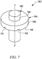
- FIG. 7 illustrates a perspective view of the push rod assembly 202 having the plurality of protruded structures, according to one embodiment of the present disclosure.
- the push rod assembly 202 may include a rod portion 702 which may be coupled to the piston 208.
- the rod portion 702 may be adapted to perform the reciprocating movement within the housing 206.
- the push rod assembly 202 may include a stopper portion 704 having an inner surface 706 and an outer surface 708 opposite to the inner surface 706.
- the inner surface 706 of the stopper portion 704 may be fixedly engaged with the rod portion 702.
- the plurality of protruded structures may be adjacently disposed on a first surface 710 of the stopper portion 704.
- the plurality of protruded structures may form a plurality of grooves 712 by being adjacently disposed.
- the plurality of grooves 712 may extend from the inner surface 706 of the stopper portion 704 towards the outer surface 708 of the stopper portion 704.
- the plurality of grooves 712 may allow the fluid to flow towards the outer surface 708.
- the plurality of grooves 712 may allow the fluid to flow towards the outer surface 708, when the fluid is accumulated between the stopper portion 704 and the stopping assembly 204.
- the constructional and operational features of the plurality of protruded structures and the plurality of grooves 712 may be similar to the constructional and operational features of the plurality of protruded structures 302 and the plurality of grooves 508, respectively.
- the plurality of grooves 712 may extend radially from the inner surface 706 of the stopper portion 704 towards the outer surface 708 of the stopper portion 704.
- the push rod assembly 202 may include six protruded structures adjacently disposed on the first surface 710 of the stopper portion 704 forming six grooves 712 extending from the inner surface 706 towards the outer surface 708.
- at least one groove 712, from the plurality of grooves 712 may have a varying cross-section. In one embodiment, the varying cross-section of the at least one groove 712 may increase from the inner surface 706 towards the outer surface 708.
- FIG. 8 illustrates a cross-sectional view of the push rod assembly 202 of FIG. 7 , according to one embodiment of the present disclosure.
- FIG. 9 illustrates a bottom view of the push rod assembly 202 of FIG. 7 , according to one embodiment of the present disclosure.
- the push rod assembly 202 may include a plurality of protruded structures 902.
- the plurality of protruded structures 902 and the plurality of grooves 712 may be formed on the first surface 710 of the stopper portion 704.
- the piston pump 102 may include the plurality of protruded structures 302 formed on the first surface 512 of the base portion 502. In an alternative embodiment, the piston pump 102 may include the plurality of protruded structures 902 on the first surface 710 of the stopper portion 704. In another embodiment, the piston pump 102 may include the plurality of protruded structures 302 and the plurality of protruded structures 902 on the first surface 710 of the base portion 502 and on the first surface 710 of the stopper portion 704, respectively.
- the present disclosure relates to the piston pump 102 having the push rod assembly 202 and the stopping assembly 204, according to one embodiment of the present disclosure.
- the piston pump 102 further includes at least one of the plurality of protruded structures 302 and the plurality of protruded structures 902 adjacently disposed on the first surface 512 of the base portion 502 and the first surface 710 of the stopper portion 704, respectively.
- the plurality of protruded structures 302, 902 form the plurality of grooves 508, 712 extending outwardly from the inner surface 504, 706 of one of the base portion 502 and the stopper portion 704.
- the plurality of protruded structures 302, 902 are formed on the push rod assembly 202 and the stopping assembly 204 for allowing the fluid to flow towards the outer surface 506, 708 such that the fluid does not accumulate on the stopping assembly 204 or between the push rod assembly 202 and the stopping assembly 204.
- the scope of the present disclosure is not limited to the push rod assembly 202 and the stopping assembly 204 of the piston pump 102.
- the plurality of protruded structures 302, 902 may be formed on any surface of any component to avoid accumulation of fluid, without departing from the scope of the present disclosure.
- the piston pump 102 having the push rod assembly 202 and the stopping assembly 204 of the present disclosure offers a comprehensive approach for avoiding accumulation of the fluid on a surface.
- the plurality of protruded structures 302, 902 can be formed on any surface, for example, on the first surface 512 of the base portion 502 of the stopping assembly 204 and the first surface 710 of the stopper portion 704 of the push rod assembly 202.
- the plurality of protruded structures 302, 902 forms the plurality of grooves 508, 712 which allows the fluid to flow towards the outer surface 506, 708 and not towards the sealing ring 216. Therefore, the fluid is not accumulated on the stopping assembly 204 or between the stopping assembly 204 and the push rod assembly 202. Further, as the fluid flows towards the outer surface 506, 708, a possibility of development of pressure surges in the fluid is eliminated.
- the varying cross-section of the plurality of grooves 508, 712 ensures that the fluid flows in an outward direction. Consequently, the volume of the fluid per work cycle of the piston pump 102 passing through the sealing ring 216 is significantly reduced. Owing to the elimination of the pressure surges and lesser volume of the fluid flowing past the sealing ring 216, the service life of the sealing ring 216 is increased. The lesser volume of the fluid flowing towards the sealing ring 216 may also minimize leakage of the fluid into the lubrication oil.
- the plurality of protruded structures 302, 902 can be formed either on the push rod assembly 202 or on the stopping assembly 204, or on both. Therefore, the present disclosure provides flexibility in terms of providing an outward flow to the fluid. Moreover, the construction of the plurality of protruded structures 302, 902 and the plurality of grooves 508, 712 is simple. As a result, the plurality of protruded structures 302, 902 and the plurality of grooves 508, 712 can be easily manufactured and accommodated on the push rod assembly 202 and the stopping assembly 204. Further, the plurality of protruded structures 302, 902 can be formed on already existing components of the piston pump 102.
- the piston pump 102 of the present disclosure does not include additional components for facilitating an outward flow of the fluid. Therefore, the present disclosure offers the piston pump 102 having the plurality of protruded structures 302, 902 on the push rod assembly 202 and the stopping assembly 204 that is simple, effective, economical, and flexible.
Landscapes
- Engineering & Computer Science (AREA)
- Mechanical Engineering (AREA)
- General Engineering & Computer Science (AREA)
- Chemical & Material Sciences (AREA)
- Combustion & Propulsion (AREA)
- Reciprocating Pumps (AREA)
Abstract
Description
- The present disclosure relates to piston pumps, and more particularly relates to a push rod assembly, a stopping assembly, and a piston pump having the push rod assembly and the stopping assembly.
- Internal combustion engines are often equipped with a piston pump in a fuel supply system. The piston pump may feed fuel from a reservoir to a fuel injection valve. The piston pump usually includes a push rod adapted to make a reciprocating movement within a chamber, a stopper for concentrically receiving the push rod, and a sealing ring disposed between the push rod and the stopper. The stopper is also utilized for limiting a downward movement of the push rod. In particular, the stopper may be disposed at a bottom of a housing of the piston pump, and may limit the downward movement of the push rod, when a bottom surface of the push rod comes into contact with a top surface of the stopper.
- Further, the fuel is usually accumulated in the chamber, and is moved by the reciprocating movement of the push rod. For example, when the push rod is moving towards the top surface of the stopper, the fuel available in the chamber gets pressurized between the push rod and the stopper. As a result, pressure surges are created in the fuel flowing towards the sealing ring hampering the operation of the sealing ring. Generally, sealing rings are not manufactured to withstand such pressure surges of the fuel. As a result, the sealing rings fail and have to be frequently replaced. This would lead to inconvenience and expenses with regard to replacement and maintenance of the sealing ring. Moreover, after flowing past the sealing ring, the fuel may get mixed with lubrication oil resulting into a dilution of the lubrication oil. The lubrication oil may also have to be replaced once the dilution makes the lubrication oil unusable, for example, due to decrease in viscosity. The maintenance of the sealing ring and the lubrication oil may lead to a significant machine downtime and affect an overall performance of an engine.
- In one aspect of the present disclosure, a stopping assembly of a piston pump is provided. The stopping assembly includes a base portion having an inner surface for movably receiving a push rod assembly of the piston pump and an outer surface opposite to the inner surface engaged with a housing of the piston pump. The stopping assembly also includes a plurality of protruded structures adjacently disposed on the base portion forming a plurality of grooves. The plurality of grooves extends from the inner surface towards the outer surface to allow fluid to flow towards the outer surface.
- In another aspect of the present disclosure, a push rod assembly of a piston pump is provided. The push rod assembly includes a rod coupled to a piston of the piston pump. The rod is adapted to perform a reciprocating movement within a housing of the piston pump. The push rod assembly includes a stopper portion having an inner surface fixedly engaged with the rod and an outer surface opposite to the inner surface. The push rod assembly further includes a plurality of protruded structures adjacently disposed on a first surface of the stopper portion forming a plurality of grooves extending from the inner surface towards the outer surface to allow fluid to flow towards the outer surface.
- In yet another aspect of the present disclosure, a piston pump is provided. The piston pump includes a housing, a piston movably disposed in the housing, and a push rod assembly coupled to the piston. The push rod assembly is adapted to perform a reciprocating movement within the housing along with the piston. The push rod assembly includes a rod portion and a stopper portion. The stopper portion has an inner surface fixedly engaged with the rod portion and an outer surface opposite to the inner surface. The piston pump includes a stopping assembly for limiting a movement of the push rod assembly within the piston pump. The stopping assembly includes a base portion having an inner surface for movably receiving the push rod assembly and an outer surface opposite to the inner surface engaged with the housing. The piston pump further includes a plurality of protruded structures adjacently disposed on at least one of a first surface of the stopper portion and a first surface of the base portion. The plurality of protruded structures forms a plurality of grooves extending outwardly from the inner surface of one of the stopper portion and the base portion.
- Other features and aspects of this disclosure will be apparent from the following description and the accompanying drawings.
-
-
FIG. 1 is a block diagram of an internal combustion engine with a piston pump, according to one embodiment of the present disclosure; -
FIG. 2 is a cross-sectional view of the piston pump having a push rod assembly and a stopping assembly, according to one embodiment of the present disclosure; -
FIG. 3 is a perspective view of the push rod assembly and the stopping assembly, according to one embodiment of the present disclosure; -
FIG. 4 is a cross-sectional view of the push rod assembly and the stopping assembly, according to one embodiment of the present disclosure; -
FIG. 5 is a perspective view of the stopping assembly having a plurality of protruded structures, according to one embodiment of the present disclosure; -
FIG. 6 is a cross-sectional view of the stopping assembly ofFIG. 5 , according to one embodiment of the present disclosure; -
FIG. 7 is a perspective view of the push rod assembly having a plurality of protruded structures, according to one embodiment of the present disclosure; -
FIG. 8 is a cross-sectional view of the push rod assembly ofFIG. 7 , according to one embodiment of the present disclosure; and -
FIG. 9 is a bottom view of the push rod assembly ofFIG. 7 , according to one embodiment of the present disclosure. - Wherever possible, the same reference numbers will be used throughout the drawings to refer to the same or the like parts.
FIG. 1 is a block diagram of aninternal combustion engine 100 with apiston pump 102, according to one embodiment of the present disclosure. In the present embodiment, thepiston pump 102 may be employed as a high-pressure fuel pump in a machine (not shown) having theinternal combustion engine 100. In other embodiments, thepiston pump 102 may be employed in other systems of the machine, such as in a braking system (not shown), without departing from the scope of the present disclosure. In the present disclosure, theinternal combustion engine 100 is interchangeably referred to asengine 100. - In one embodiment, the machine may include a
fuel supply system 104 for supplying fuel to theengine 100. In the present embodiment, thefuel supply system 104 may be a pump-line nozzle system. Thefuel supply system 104 may include, but is not limited to, afuel reservoir 106, thepiston pump 102, afuel injection nozzle 110, and an Electronic Control Unit (ECU) 112. Thefuel supply system 104 may further include afirst conduit 114 for connecting thefuel reservoir 106 with thepiston pump 102, and asecond conduit 116 for connecting thepiston pump 102 with thefuel injection nozzle 110. Therefore, thefuel reservoir 106, thefirst conduit 114, thepiston pump 102, thesecond conduit 116, and thefuel injection nozzle 110 are fluidly coupled with each other. Further, the ECU 112 may be in communication with thepiston pump 102, thefuel injection nozzle 110, and theengine 100. - In one embodiment, the fuel to be delivered to the
engine 100 may be stored in thefuel reservoir 106. The fuel may be delivered from thefuel reservoir 106 to thepiston pump 102 through thefirst conduit 114. In one embodiment, thefuel supply system 104 may include a supply pump (not shown) for pumping the fluid from thefuel reservoir 106 towards thepiston pump 102. Thepiston pump 102 may pressurize the fuel, and may then supply the pressurized fuel to thefuel injection nozzle 110 through thesecond conduit 116. The operational and constructional features of thepiston pump 102 are explained in detail in the description ofFIG. 2 . - In one embodiment, the
fuel injection nozzle 110 may be disposed in a cylinder head (not shown) of a cylinder (not shown) of theengine 100. Thefuel injection nozzle 110 may be adapted to inject the fuel received from thepiston pump 102 into the cylinder. In one embodiment, thefuel injection nozzle 110 may include a needle valve (not shown) for controlling a flow of the fuel towards the cylinder. In an open state, the needle valve of thefuel injection nozzle 110 may allow the fuel from thesecond conduit 116 to flow towards the cylinder of theengine 100. In a closed state, the needle valve of thefuel injection nozzle 110 may block the flow of the fuel from thesecond conduit 116 towards the cylinder. In one embodiment, theECU 112 may control the opening and closing of the needle valve of thefuel injection nozzle 110 for selectively allowing the fuel to enter the cylinder of theengine 100 through thefuel injection nozzle 110. - In one embodiment, the
engine 100 may include multiple cylinders. In such an embodiment, for each cylinder of theengine 100, thefuel supply system 104 may include onefuel injection nozzle 110. Further, thefuel supply system 104 may include onepiston pump 102 for eachfuel injection nozzle 110. Therefore, in one embodiment with multiplefuel injection nozzles 110, thefuel supply system 104 may include multiple piston pumps 102. Although the present disclosure is explained with regard to onepiston pump 102 for onefuel injection nozzle 110, the present disclosure is equally applicable for the multiple piston pumps 102 supplying the fuel to the multiplefuel injection nozzles 110. -
FIG. 2 illustrates a cross-sectional view of thepiston pump 102 having apush rod assembly 202 and a stoppingassembly 204, according to one embodiment of the present disclosure. Thepiston pump 102 may include ahousing 206, apiston 208 movably disposed within thehousing 206, thepush rod assembly 202 coupled to thepiston 208, and the stoppingassembly 204 disposed at or near abottom 210 of thehousing 206. The fuel from thesecond conduit 116 may enter thehousing 206 through thefuel injection nozzle 110, and may lubricate thepiston 208. - The
piston 208 may be coupled to thepush rod assembly 202 which may in turn be coupled to an external push rod assembly (not shown). The external push rod assembly may enable thepush rod assembly 202 to perform a reciprocating movement within thehousing 206. Further, since thepiston 208 is coupled to thepush rod assembly 202, thepiston 208 may also perform a reciprocating movement within thehousing 206. Therefore, thepush rod assembly 202 may be adapted to perform the reciprocating movement within thehousing 206 along with thepiston 208. A region of movement of thepush rod assembly 202 within thehousing 206 may be referred to as achamber 212. The constructional and operational features of thepush rod assembly 202 are explained in detail in the description ofFIG. 3 ,FIG. 4 ,FIG. 7 ,FIG. 8 , andFIG. 9 . - In one embodiment, the
piston pump 102 may also include one ormore springs 214 disposed within thechamber 212. In such an embodiment, for the reciprocating movement, the external push rod assembly may push thepush rod assembly 202 towards thepiston 208 whereas thesprings 214 may push thepush rod assembly 202 back towards thebottom 210 of thehousing 206. - In one embodiment, the movement of the
push rod assembly 202 towards thebottom 210 of thehousing 206 may be limited by the stoppingassembly 204. In one embodiment, the stoppingassembly 204 may be a flange-like structure, and may be mounted in thehousing 206 by using fasteners, such as screws. During the reciprocating movement, thepush rod assembly 202 may be moving through the stoppingassembly 204. In one embodiment, the movement of thepush rod assembly 202 may be restricted when thepush rod assembly 202 comes in contact with a first surface (shown inFIG. 3 ) of the stoppingassembly 204, for example, when thepiston 208 is at a bottom dead center. The constructional and operational features of the stoppingassembly 204 are explained in detail in the description ofFIG. 3 ,FIG. 4 ,FIG. 5 , andFIG. 6 . - In one embodiment, the
piston pump 102 may further include asealing ring 216 disposed between thepush rod assembly 202 and the stoppingassembly 204. The sealingring 216 may be disposed in order to ensure a smooth movement of thepush rod assembly 202 through the stoppingassembly 204. Further, the sealingring 216 may provide sealing between thepush rod assembly 202 and the stoppingassembly 204. Therefore, the sealingring 216 may restrict the fuel or any other fluid from flowing between thepush rod assembly 202 and the stoppingassembly 204. - In one embodiment, the reciprocating movement of the
push rod assembly 202 may cause a lubrication oil to be drawn into thehousing 206 from a fluid reservoir (not shown). In one embodiment, the lubrication oil may be accumulated in thechamber 212. On the other hand, due to the reciprocating movement of thepiston 208, the fuel coming through thefuel injection nozzle 110 may naturally flow along sides of thepiston 208, and may also get accumulated in thechamber 212. Therefore, in thechamber 212, the fuel may mix with the lubrication oil to form a mixed fluid, also referred to as fluid. In one embodiment, the fluid may include equal to or more than 90% as the fuel, by volume. - In one embodiment, at least one of the stopping
assembly 204 and thepush rod assembly 202 may include a plurality of protruded structures (shown inFIG. 3 ) in such a manner that when the fluid is pressurized during the reciprocating movement of thepush rod assembly 202 and thepiston 208, the fluid by-passes the sealingring 216 by flowing radially towards the sides of thepush rod assembly 202. In one embodiment, the plurality of protruded structures may be formed on at least one of the stoppingassembly 204 and thepush rod assembly 202 by a milling operation. In other embodiments, the plurality of protruded structures may be formed on at least one of the stoppingassembly 204 and thepush rod assembly 202 by other manufacturing techniques, without departing from the scope of the present disclosure. - In one embodiment, when being pressurized, the fluid may follow a flow path F1, where the fluid may flow upwards through a
conduit 218 into thechamber 212. From thechamber 212, the fluid may flow out of thehousing 206, when the fluid becomes unusable. The flow of the fluid along the flow path F1 may result in a controlled sleeve lubrication of thepiston 208 and thepush rod assembly 202. -
FIG. 3 illustrates a perspective view of thepush rod assembly 202 and the stoppingassembly 204, according to one embodiment of the present disclosure. In the present embodiment, the stoppingassembly 204 may include a plurality of protrudedstructures 302. As shown, thepush rod assembly 202 may be adapted to move through the stoppingassembly 204 for performing the reciprocating movement. The movement of thepush rod assembly 202 towards thebottom 210 of thehousing 206 may be restricted when thepush rod assembly 202 comes in contact with thefirst surface 304 of the stoppingassembly 204.FIG. 4 illustrates a cross-sectional view of thepush rod assembly 202 and the stoppingassembly 204, according to the embodiment ofFIG. 3 . As shown, the sealingring 216 may be disposed between thepush rod assembly 202 and the stoppingassembly 204. -
FIG. 5 illustrates a perspective view of the stoppingassembly 204 having the plurality of protrudedstructures 302, according to one embodiment of the present disclosure. The stoppingassembly 204 may include abase portion 502 having aninner surface 504 and anouter surface 506 opposite to theinner surface 504. Theinner surface 504 may define abore 510 in thebase portion 502 for movably receiving thepush rod assembly 202. Theinner surface 504 may be adapted to receive thepush rod assembly 202 for accommodating the reciprocating movement of thepush rod assembly 202. Further, theouter surface 506 may be adapted to engage with thehousing 206 of thepiston pump 102. - The plurality of protruded
structures 302 may be adjacently disposed on thebase portion 502. The plurality of protrudedstructures 302 may be formed on afirst surface 512 of thebase portion 502. The plurality of protrudedstructures 302 may be adjacently disposed forming a plurality ofgrooves 508 on thefirst surface 512 of thebase portion 502. The plurality ofgrooves 508 may extend from theinner surface 504 of the stoppingassembly 204 towards theouter surface 506 of the stoppingassembly 204 for allowing the fluid to flow towards theouter surface 506. In one embodiment, when the fluid is pressurized between thepush rod assembly 202 and the stoppingassembly 204, the fluid may flow towards theouter surface 506 of the stoppingassembly 204 through the plurality ofgrooves 508. - In one embodiment, the plurality of
grooves 508 may extend radially from theinner surface 504 towards theouter surface 506. For example, with regard to a vertical axis YY' of thepush rod assembly 202, the plurality ofgrooves 508 may be extending in a radially outward direction. In the embodiment shown inFIG. 5 , the stoppingassembly 204 includes six protrudedstructures 302 adjacently disposed on thebase portion 502 forming sixgrooves 508 extending from theinner surface 504 towards theouter surface 506. - In one embodiment, at least one
groove 508, from the plurality ofgrooves 508 may have a square cross-section, a rectangular cross-section, or a circular cross-section. In one embodiment, the at least onegroove 508 may have a varying cross-section. In one embodiment, the varying cross-section of the at least onegroove 508 may be increasing from theinner surface 504 towards theouter surface 506. In one embodiment, the cross-section of the at least onegroove 508 may be varied by varying one of a width or a depth of the at least onegroove 508. In one embodiment, the cross-section of the at least onegroove 508 may be varied by varying the width and the depth of the at least onegroove 508. -
FIG. 6 is a cross-sectional view of the stoppingassembly 204 ofFIG. 5 , according to one embodiment of the present disclosure. As shown, the sealingring 216 may be disposed within the stoppingassembly 204 in such a manner that the sealingring 216 may contact thepush rod assembly 202 during the reciprocating movement of thepush rod assembly 202 through thebore 510 of the stoppingassembly 204. - In one embodiment, instead of the stopping
assembly 204 having the plurality of protrudedstructures 302, thepush rod assembly 202 may include a plurality of protruded structures (shown inFIG. 9 ).FIG. 7 illustrates a perspective view of thepush rod assembly 202 having the plurality of protruded structures, according to one embodiment of the present disclosure. - The
push rod assembly 202 may include arod portion 702 which may be coupled to thepiston 208. Therod portion 702 may be adapted to perform the reciprocating movement within thehousing 206. Thepush rod assembly 202 may include astopper portion 704 having aninner surface 706 and anouter surface 708 opposite to theinner surface 706. Theinner surface 706 of thestopper portion 704 may be fixedly engaged with therod portion 702. The plurality of protruded structures may be adjacently disposed on afirst surface 710 of thestopper portion 704. The plurality of protruded structures may form a plurality ofgrooves 712 by being adjacently disposed. The plurality ofgrooves 712 may extend from theinner surface 706 of thestopper portion 704 towards theouter surface 708 of thestopper portion 704. The plurality ofgrooves 712 may allow the fluid to flow towards theouter surface 708. In one embodiment, the plurality ofgrooves 712 may allow the fluid to flow towards theouter surface 708, when the fluid is accumulated between thestopper portion 704 and the stoppingassembly 204. - In one embodiment, the constructional and operational features of the plurality of protruded structures and the plurality of
grooves 712 may be similar to the constructional and operational features of the plurality of protrudedstructures 302 and the plurality ofgrooves 508, respectively. The plurality ofgrooves 712 may extend radially from theinner surface 706 of thestopper portion 704 towards theouter surface 708 of thestopper portion 704. In one embodiment, thepush rod assembly 202 may include six protruded structures adjacently disposed on thefirst surface 710 of thestopper portion 704 forming sixgrooves 712 extending from theinner surface 706 towards theouter surface 708. In one embodiment, at least onegroove 712, from the plurality ofgrooves 712, may have a varying cross-section. In one embodiment, the varying cross-section of the at least onegroove 712 may increase from theinner surface 706 towards theouter surface 708. -
FIG. 8 illustrates a cross-sectional view of thepush rod assembly 202 ofFIG. 7 , according to one embodiment of the present disclosure. Further,FIG. 9 illustrates a bottom view of thepush rod assembly 202 ofFIG. 7 , according to one embodiment of the present disclosure. In the present embodiment, thepush rod assembly 202 may include a plurality of protrudedstructures 902. The plurality of protrudedstructures 902 and the plurality ofgrooves 712 may be formed on thefirst surface 710 of thestopper portion 704. - As would be gathered, in one embodiment, the
piston pump 102 may include the plurality of protrudedstructures 302 formed on thefirst surface 512 of thebase portion 502. In an alternative embodiment, thepiston pump 102 may include the plurality of protrudedstructures 902 on thefirst surface 710 of thestopper portion 704. In another embodiment, thepiston pump 102 may include the plurality of protrudedstructures 302 and the plurality of protrudedstructures 902 on thefirst surface 710 of thebase portion 502 and on thefirst surface 710 of thestopper portion 704, respectively. - The present disclosure relates to the
piston pump 102 having thepush rod assembly 202 and the stoppingassembly 204, according to one embodiment of the present disclosure. Thepiston pump 102 further includes at least one of the plurality of protrudedstructures 302 and the plurality of protrudedstructures 902 adjacently disposed on thefirst surface 512 of thebase portion 502 and thefirst surface 710 of thestopper portion 704, respectively. The plurality of protrudedstructures grooves inner surface base portion 502 and thestopper portion 704. - In the present disclosure, the plurality of protruded
structures push rod assembly 202 and the stoppingassembly 204 for allowing the fluid to flow towards theouter surface assembly 204 or between thepush rod assembly 202 and the stoppingassembly 204. However, the scope of the present disclosure is not limited to thepush rod assembly 202 and the stoppingassembly 204 of thepiston pump 102. In other embodiments, the plurality of protrudedstructures - The
piston pump 102 having thepush rod assembly 202 and the stoppingassembly 204 of the present disclosure offers a comprehensive approach for avoiding accumulation of the fluid on a surface. The plurality of protrudedstructures first surface 512 of thebase portion 502 of the stoppingassembly 204 and thefirst surface 710 of thestopper portion 704 of thepush rod assembly 202. The plurality of protrudedstructures grooves outer surface ring 216. Therefore, the fluid is not accumulated on the stoppingassembly 204 or between the stoppingassembly 204 and thepush rod assembly 202. Further, as the fluid flows towards theouter surface - Also, the varying cross-section of the plurality of
grooves piston pump 102 passing through the sealingring 216 is significantly reduced. Owing to the elimination of the pressure surges and lesser volume of the fluid flowing past the sealingring 216, the service life of the sealingring 216 is increased. The lesser volume of the fluid flowing towards the sealingring 216 may also minimize leakage of the fluid into the lubrication oil. - In addition, the plurality of protruded
structures push rod assembly 202 or on the stoppingassembly 204, or on both. Therefore, the present disclosure provides flexibility in terms of providing an outward flow to the fluid. Moreover, the construction of the plurality of protrudedstructures grooves structures grooves push rod assembly 202 and the stoppingassembly 204. Further, the plurality of protrudedstructures piston pump 102. Therefore, thepiston pump 102 of the present disclosure does not include additional components for facilitating an outward flow of the fluid. Therefore, the present disclosure offers thepiston pump 102 having the plurality of protrudedstructures push rod assembly 202 and the stoppingassembly 204 that is simple, effective, economical, and flexible. - While aspects of the present disclosure have been particularly shown and described with reference to the implementations above, it will be understood by those skilled in the art that various additional implementations may be contemplated by the modification of the disclosed machines, systems and methods without departing from the spirit and scope of what is disclosed. Such implementations should be understood to fall within the scope of the present disclosure as determined based upon the claims and any equivalents thereof.
Claims (13)
- A stopping assembly (204) of a piston pump (102), the stopping assembly (204) comprising:a base portion (502) having an inner surface (504) for movably receiving a push rod assembly (202) of the piston pump (102) and an outer surface (506) opposite to the inner surface (504) configured to be engaged with a housing of the piston pump (102); anda plurality of protruded structures (302) adjacently disposed on the base portion (502) forming a plurality of grooves (508) extending from the inner surface (504) towards the outer surface (506) to allow fluid to flow towards the outer surface (506).
- The stopping assembly (204) of claim 1, wherein the plurality of grooves (508) extends radially from the inner surface (504) towards the outer surface (506).
- The stopping assembly (204) of claim 1 or 2, wherein the inner surface (504) defines a bore (510) in the base portion (502) for accommodating the push rod assembly (202).
- The stopping assembly (204) of any one of the preceding claims, wherein six protruded structures (302) are adjacently disposed on the base portion (502) forming six grooves (508) extending from the inner surface (504) towards the outer surface (506).
- The stopping assembly (204) of any one of the preceding claims, wherein at least one groove (508), from the plurality of grooves (508), has a varying cross-section.
- The stopping assembly (204) of claim 5, wherein the varying cross-section of the at least one groove (508) increases from the inner surface (504) towards the outer surface (506).
- A push rod assembly (202) of a piston pump (102), the push rod assembly (202) comprising:a rod portion (702) coupled to a piston (208) of the piston pump (102), the rod portion (702) adapted to perform a reciprocating movement within a housing (206) of the piston pump (102);a stopper portion (704) having an inner surface (706) fixedly engaged with the rod portion (702) and an outer surface (708) opposite to the inner surface (706); anda plurality of protruded structures (902) adjacently disposed on a first surface (710) of the stopper portion (704) forming a plurality of grooves (712) extending from the inner surface (706) towards the outer surface (708) to allow fluid to flow towards the outer surface (708).
- The push rod assembly (202) of claim 7, wherein the plurality of grooves (712) extends radially from the inner surface (706) towards the outer surface (708).
- The push rod assembly (202) of claim 7, wherein six protruded structures (902) are adjacently disposed on the first surface of the stopper portion (704) forming six grooves (712) extending from the inner surface (706) towards the outer surface (708).
- The push rod assembly (202) of claim 7, wherein at least one groove (712), from the plurality of grooves (712), has a varying cross-section.
- The push rod assembly (202) of claim 10, wherein the varying cross-section of the at least one groove (712) increases from the inner surface (706) towards the outer surface (708).
- A piston pump (102) comprising:a housing (206);a piston (208) movably disposed in the housing (206);a push rod assembly (202) coupled to the piston (208) to perform a reciprocating movement within the housing (206) along with the piston (208), the push rod assembly (202) comprising:a rod portion (702); anda stopper portion (704) having an inner surface (706) fixedly engaged with the rod portion (702) and an outer surface (708) opposite to the inner surface (706);a stopping assembly (204) for limiting a movement of the push rod assembly (202) within the piston pump (102), the stopping assembly (204) comprising:a base portion (502) having an inner surface (504) for movably receiving the push rod assembly (202) and an outer surface (506) opposite to the inner surface (504) engaged with the housing (206); anda plurality of protruded structures (902, 302) adjacently disposed on at least one of a first surface (710) of the stopper portion (704) and a first surface (304) of the base portion (502), the plurality of protruded structures (902, 302) forming a plurality of grooves (712, 508) extending outwardly from the inner surface (706, 504) of one of the stopper portion (704) and the base portion (502).
- The piston pump (102) of claim 12, wherein the inner surface (504) of the base portion (502) defines a bore (510) in the base portion (502) for accommodating the push rod assembly (202).
Applications Claiming Priority (1)
| Application Number | Priority Date | Filing Date | Title |
|---|---|---|---|
| GB1617038.3A GB2554731B (en) | 2016-10-07 | 2016-10-07 | Piston pump having push rod assembly and stopping assembly |
Publications (2)
| Publication Number | Publication Date |
|---|---|
| EP3306092A1 true EP3306092A1 (en) | 2018-04-11 |
| EP3306092B1 EP3306092B1 (en) | 2019-07-03 |
Family
ID=57610542
Family Applications (1)
| Application Number | Title | Priority Date | Filing Date |
|---|---|---|---|
| EP17193080.3A Active EP3306092B1 (en) | 2016-10-07 | 2017-09-26 | Piston pump having push rod assembly and stopping assembly |
Country Status (4)
| Country | Link |
|---|---|
| US (1) | US10385846B2 (en) |
| EP (1) | EP3306092B1 (en) |
| CN (1) | CN107917029B (en) |
| GB (1) | GB2554731B (en) |
Citations (3)
| Publication number | Priority date | Publication date | Assignee | Title |
|---|---|---|---|---|
| EP0237112A1 (en) * | 1986-03-04 | 1987-09-16 | Holthuis B.V. | Valve arrangement for use in a displacement pump |
| FR2954417A1 (en) * | 2009-12-21 | 2011-06-24 | Bosch Gmbh Robert | Piston pump i.e. recirculating pump, for hydraulic dual circuit vehicle brake system, has path limitation unit that limits stroke of pistons, which are lifted from tappet circumference when tappet is removed from pistons |
| EP2685103A1 (en) * | 2011-03-08 | 2014-01-15 | Sanden Corporation | Valve device for compressor |
Family Cites Families (11)
| Publication number | Priority date | Publication date | Assignee | Title |
|---|---|---|---|---|
| US4714066A (en) * | 1980-08-14 | 1987-12-22 | Jordan Robert D | Fuel injector system |
| DE3630799A1 (en) * | 1986-03-22 | 1987-09-24 | Bosch Gmbh Robert | FUEL INJECTION PUMP FOR INTERNAL COMBUSTION ENGINES |
| DE4409555C2 (en) * | 1994-03-19 | 2003-04-17 | Caterpillar Motoren Gmbh & Co | Device for generating pressure for a pressure oil lock of an injection pump |
| CN100575701C (en) * | 2008-04-30 | 2009-12-30 | 林波 | Metering pumps and their drives |
| CA2719635C (en) * | 2010-11-01 | 2017-10-31 | Gotohti.Com Inc. | Telescopic piston for pump |
| FR2979954B1 (en) * | 2011-09-12 | 2015-02-20 | Peugeot Citroen Automobiles Sa | ASSEMBLY OF A COMBUSTION ENGINE AND A PUMP AND VEHICLE COMPRISING SUCH AN ASSEMBLY |
| JP5459329B2 (en) * | 2012-01-31 | 2014-04-02 | 株式会社デンソー | Supply pump |
| US9755811B2 (en) | 2012-06-25 | 2017-09-05 | Telefonaktiebolaget Lm Ericsson (Publ) | Method, computer program and apparatus for transmission signal rank determination |
| DE102014014475A1 (en) * | 2014-09-27 | 2016-03-31 | Man Diesel & Turbo Se | Fuel pump |
| JP6354530B2 (en) * | 2014-11-12 | 2018-07-11 | 株式会社デンソー | High pressure fuel pump |
| GB2563663A (en) * | 2017-06-23 | 2018-12-26 | Caterpillar Motoren Gmbh & Co | Method to calibrate a fuel injection pump |
-
2016
- 2016-10-07 GB GB1617038.3A patent/GB2554731B/en active Active
-
2017
- 2017-09-26 EP EP17193080.3A patent/EP3306092B1/en active Active
- 2017-09-30 CN CN201710915679.0A patent/CN107917029B/en active Active
- 2017-10-06 US US15/726,879 patent/US10385846B2/en active Active
Patent Citations (3)
| Publication number | Priority date | Publication date | Assignee | Title |
|---|---|---|---|---|
| EP0237112A1 (en) * | 1986-03-04 | 1987-09-16 | Holthuis B.V. | Valve arrangement for use in a displacement pump |
| FR2954417A1 (en) * | 2009-12-21 | 2011-06-24 | Bosch Gmbh Robert | Piston pump i.e. recirculating pump, for hydraulic dual circuit vehicle brake system, has path limitation unit that limits stroke of pistons, which are lifted from tappet circumference when tappet is removed from pistons |
| EP2685103A1 (en) * | 2011-03-08 | 2014-01-15 | Sanden Corporation | Valve device for compressor |
Also Published As
| Publication number | Publication date |
|---|---|
| CN107917029A (en) | 2018-04-17 |
| CN107917029B (en) | 2021-06-01 |
| GB201617038D0 (en) | 2016-11-23 |
| GB2554731A (en) | 2018-04-11 |
| EP3306092B1 (en) | 2019-07-03 |
| US10385846B2 (en) | 2019-08-20 |
| US20180100501A1 (en) | 2018-04-12 |
| GB2554731B (en) | 2019-04-03 |
Similar Documents
| Publication | Publication Date | Title |
|---|---|---|
| KR20150093709A (en) | Piston fuel pump for an internal combustion engine | |
| EP3482061B1 (en) | High-pressure fuel pump | |
| EP3084204B1 (en) | High pressure pump | |
| CN104204550B (en) | Fluid cylinder | |
| US10385846B2 (en) | Piston pump having push rod assembly and stopping assembly | |
| EP3298265B1 (en) | Fuel pump apparatus | |
| KR102244311B1 (en) | Fuel pump | |
| CN105863916A (en) | High pressure fuel pump | |
| DE102013010232A1 (en) | Check valve for a fuel system | |
| CN107345516B (en) | Plunger sealing ring for high-pressure fuel pump and corresponding high-pressure fuel pump | |
| KR102252934B1 (en) | Fuel pump | |
| CN216842003U (en) | Two-stage oil return injection pump and diesel engine | |
| CN204610267U (en) | A kind of conveying cylinder and pumping machine | |
| CN110691903B (en) | Fuel pump for supplying fuel to internal combustion piston engine | |
| DE19847044C2 (en) | Radial piston pump | |
| CN211448869U (en) | Plunger sleeve of diesel engine | |
| DE102013216983A1 (en) | pump | |
| US11982252B2 (en) | Fuel pump assembly | |
| KR101204635B1 (en) | Fuel injection pump with umbrella plunger guide | |
| CN210289988U (en) | Control valve body for high-pressure common rail oil sprayer | |
| JP6806769B2 (en) | Fuel pump assembly | |
| EP3601778B1 (en) | A fuel pump for supplying fuel to an internal combustion piston engine | |
| JP2023175312A (en) | fuel injection pump | |
| KR20150010877A (en) | Injection device for fuel injection pump | |
| KR101564183B1 (en) | Fuel injection pump and internal combustion engine |
Legal Events
| Date | Code | Title | Description |
|---|---|---|---|
| PUAI | Public reference made under article 153(3) epc to a published international application that has entered the european phase |
Free format text: ORIGINAL CODE: 0009012 |
|
| STAA | Information on the status of an ep patent application or granted ep patent |
Free format text: STATUS: THE APPLICATION HAS BEEN PUBLISHED |
|
| AK | Designated contracting states |
Kind code of ref document: A1 Designated state(s): AL AT BE BG CH CY CZ DE DK EE ES FI FR GB GR HR HU IE IS IT LI LT LU LV MC MK MT NL NO PL PT RO RS SE SI SK SM TR |
|
| AX | Request for extension of the european patent |
Extension state: BA ME |
|
| STAA | Information on the status of an ep patent application or granted ep patent |
Free format text: STATUS: REQUEST FOR EXAMINATION WAS MADE |
|
| 17P | Request for examination filed |
Effective date: 20180928 |
|
| RBV | Designated contracting states (corrected) |
Designated state(s): AL AT BE BG CH CY CZ DE DK EE ES FI FR GB GR HR HU IE IS IT LI LT LU LV MC MK MT NL NO PL PT RO RS SE SI SK SM TR |
|
| GRAP | Despatch of communication of intention to grant a patent |
Free format text: ORIGINAL CODE: EPIDOSNIGR1 |
|
| STAA | Information on the status of an ep patent application or granted ep patent |
Free format text: STATUS: GRANT OF PATENT IS INTENDED |
|
| RIC1 | Information provided on ipc code assigned before grant |
Ipc: F04B 53/14 20060101AFI20181218BHEP |
|
| INTG | Intention to grant announced |
Effective date: 20190115 |
|
| GRAS | Grant fee paid |
Free format text: ORIGINAL CODE: EPIDOSNIGR3 |
|
| GRAA | (expected) grant |
Free format text: ORIGINAL CODE: 0009210 |
|
| STAA | Information on the status of an ep patent application or granted ep patent |
Free format text: STATUS: THE PATENT HAS BEEN GRANTED |
|
| AK | Designated contracting states |
Kind code of ref document: B1 Designated state(s): AL AT BE BG CH CY CZ DE DK EE ES FI FR GB GR HR HU IE IS IT LI LT LU LV MC MK MT NL NO PL PT RO RS SE SI SK SM TR |
|
| REG | Reference to a national code |
Ref country code: GB Ref legal event code: FG4D |
|
| REG | Reference to a national code |
Ref country code: CH Ref legal event code: EP Ref country code: AT Ref legal event code: REF Ref document number: 1151336 Country of ref document: AT Kind code of ref document: T Effective date: 20190715 |
|
| REG | Reference to a national code |
Ref country code: IE Ref legal event code: FG4D |
|
| REG | Reference to a national code |
Ref country code: DE Ref legal event code: R096 Ref document number: 602017005003 Country of ref document: DE |
|
| REG | Reference to a national code |
Ref country code: NL Ref legal event code: MP Effective date: 20190703 |
|
| REG | Reference to a national code |
Ref country code: LT Ref legal event code: MG4D |
|
| PG25 | Lapsed in a contracting state [announced via postgrant information from national office to epo] |
Ref country code: CZ Free format text: LAPSE BECAUSE OF FAILURE TO SUBMIT A TRANSLATION OF THE DESCRIPTION OR TO PAY THE FEE WITHIN THE PRESCRIBED TIME-LIMIT Effective date: 20190703 Ref country code: NO Free format text: LAPSE BECAUSE OF FAILURE TO SUBMIT A TRANSLATION OF THE DESCRIPTION OR TO PAY THE FEE WITHIN THE PRESCRIBED TIME-LIMIT Effective date: 20191003 Ref country code: LT Free format text: LAPSE BECAUSE OF FAILURE TO SUBMIT A TRANSLATION OF THE DESCRIPTION OR TO PAY THE FEE WITHIN THE PRESCRIBED TIME-LIMIT Effective date: 20190703 Ref country code: NL Free format text: LAPSE BECAUSE OF FAILURE TO SUBMIT A TRANSLATION OF THE DESCRIPTION OR TO PAY THE FEE WITHIN THE PRESCRIBED TIME-LIMIT Effective date: 20190703 Ref country code: BG Free format text: LAPSE BECAUSE OF FAILURE TO SUBMIT A TRANSLATION OF THE DESCRIPTION OR TO PAY THE FEE WITHIN THE PRESCRIBED TIME-LIMIT Effective date: 20191003 Ref country code: PT Free format text: LAPSE BECAUSE OF FAILURE TO SUBMIT A TRANSLATION OF THE DESCRIPTION OR TO PAY THE FEE WITHIN THE PRESCRIBED TIME-LIMIT Effective date: 20191104 Ref country code: FI Free format text: LAPSE BECAUSE OF FAILURE TO SUBMIT A TRANSLATION OF THE DESCRIPTION OR TO PAY THE FEE WITHIN THE PRESCRIBED TIME-LIMIT Effective date: 20190703 Ref country code: SE Free format text: LAPSE BECAUSE OF FAILURE TO SUBMIT A TRANSLATION OF THE DESCRIPTION OR TO PAY THE FEE WITHIN THE PRESCRIBED TIME-LIMIT Effective date: 20190703 Ref country code: HR Free format text: LAPSE BECAUSE OF FAILURE TO SUBMIT A TRANSLATION OF THE DESCRIPTION OR TO PAY THE FEE WITHIN THE PRESCRIBED TIME-LIMIT Effective date: 20190703 |
|
| PG25 | Lapsed in a contracting state [announced via postgrant information from national office to epo] |
Ref country code: AL Free format text: LAPSE BECAUSE OF FAILURE TO SUBMIT A TRANSLATION OF THE DESCRIPTION OR TO PAY THE FEE WITHIN THE PRESCRIBED TIME-LIMIT Effective date: 20190703 Ref country code: GR Free format text: LAPSE BECAUSE OF FAILURE TO SUBMIT A TRANSLATION OF THE DESCRIPTION OR TO PAY THE FEE WITHIN THE PRESCRIBED TIME-LIMIT Effective date: 20191004 Ref country code: RS Free format text: LAPSE BECAUSE OF FAILURE TO SUBMIT A TRANSLATION OF THE DESCRIPTION OR TO PAY THE FEE WITHIN THE PRESCRIBED TIME-LIMIT Effective date: 20190703 Ref country code: IS Free format text: LAPSE BECAUSE OF FAILURE TO SUBMIT A TRANSLATION OF THE DESCRIPTION OR TO PAY THE FEE WITHIN THE PRESCRIBED TIME-LIMIT Effective date: 20191103 Ref country code: LV Free format text: LAPSE BECAUSE OF FAILURE TO SUBMIT A TRANSLATION OF THE DESCRIPTION OR TO PAY THE FEE WITHIN THE PRESCRIBED TIME-LIMIT Effective date: 20190703 Ref country code: ES Free format text: LAPSE BECAUSE OF FAILURE TO SUBMIT A TRANSLATION OF THE DESCRIPTION OR TO PAY THE FEE WITHIN THE PRESCRIBED TIME-LIMIT Effective date: 20190703 |
|
| PG25 | Lapsed in a contracting state [announced via postgrant information from national office to epo] |
Ref country code: TR Free format text: LAPSE BECAUSE OF FAILURE TO SUBMIT A TRANSLATION OF THE DESCRIPTION OR TO PAY THE FEE WITHIN THE PRESCRIBED TIME-LIMIT Effective date: 20190703 |
|
| PG25 | Lapsed in a contracting state [announced via postgrant information from national office to epo] |
Ref country code: IT Free format text: LAPSE BECAUSE OF FAILURE TO SUBMIT A TRANSLATION OF THE DESCRIPTION OR TO PAY THE FEE WITHIN THE PRESCRIBED TIME-LIMIT Effective date: 20190703 Ref country code: DK Free format text: LAPSE BECAUSE OF FAILURE TO SUBMIT A TRANSLATION OF THE DESCRIPTION OR TO PAY THE FEE WITHIN THE PRESCRIBED TIME-LIMIT Effective date: 20190703 Ref country code: PL Free format text: LAPSE BECAUSE OF FAILURE TO SUBMIT A TRANSLATION OF THE DESCRIPTION OR TO PAY THE FEE WITHIN THE PRESCRIBED TIME-LIMIT Effective date: 20190703 Ref country code: EE Free format text: LAPSE BECAUSE OF FAILURE TO SUBMIT A TRANSLATION OF THE DESCRIPTION OR TO PAY THE FEE WITHIN THE PRESCRIBED TIME-LIMIT Effective date: 20190703 Ref country code: RO Free format text: LAPSE BECAUSE OF FAILURE TO SUBMIT A TRANSLATION OF THE DESCRIPTION OR TO PAY THE FEE WITHIN THE PRESCRIBED TIME-LIMIT Effective date: 20190703 |
|
| PG25 | Lapsed in a contracting state [announced via postgrant information from national office to epo] |
Ref country code: MC Free format text: LAPSE BECAUSE OF FAILURE TO SUBMIT A TRANSLATION OF THE DESCRIPTION OR TO PAY THE FEE WITHIN THE PRESCRIBED TIME-LIMIT Effective date: 20190703 Ref country code: SM Free format text: LAPSE BECAUSE OF FAILURE TO SUBMIT A TRANSLATION OF THE DESCRIPTION OR TO PAY THE FEE WITHIN THE PRESCRIBED TIME-LIMIT Effective date: 20190703 Ref country code: IS Free format text: LAPSE BECAUSE OF FAILURE TO SUBMIT A TRANSLATION OF THE DESCRIPTION OR TO PAY THE FEE WITHIN THE PRESCRIBED TIME-LIMIT Effective date: 20200224 Ref country code: SK Free format text: LAPSE BECAUSE OF FAILURE TO SUBMIT A TRANSLATION OF THE DESCRIPTION OR TO PAY THE FEE WITHIN THE PRESCRIBED TIME-LIMIT Effective date: 20190703 |
|
| REG | Reference to a national code |
Ref country code: DE Ref legal event code: R097 Ref document number: 602017005003 Country of ref document: DE |
|
| PLBE | No opposition filed within time limit |
Free format text: ORIGINAL CODE: 0009261 |
|
| STAA | Information on the status of an ep patent application or granted ep patent |
Free format text: STATUS: NO OPPOSITION FILED WITHIN TIME LIMIT |
|
| PG2D | Information on lapse in contracting state deleted |
Ref country code: IS |
|
| PG25 | Lapsed in a contracting state [announced via postgrant information from national office to epo] |
Ref country code: LU Free format text: LAPSE BECAUSE OF NON-PAYMENT OF DUE FEES Effective date: 20190926 Ref country code: IE Free format text: LAPSE BECAUSE OF NON-PAYMENT OF DUE FEES Effective date: 20190926 |
|
| 26N | No opposition filed |
Effective date: 20200603 |
|
| REG | Reference to a national code |
Ref country code: BE Ref legal event code: MM Effective date: 20190930 |
|
| PG25 | Lapsed in a contracting state [announced via postgrant information from national office to epo] |
Ref country code: SI Free format text: LAPSE BECAUSE OF FAILURE TO SUBMIT A TRANSLATION OF THE DESCRIPTION OR TO PAY THE FEE WITHIN THE PRESCRIBED TIME-LIMIT Effective date: 20190703 Ref country code: BE Free format text: LAPSE BECAUSE OF NON-PAYMENT OF DUE FEES Effective date: 20190930 |
|
| PG25 | Lapsed in a contracting state [announced via postgrant information from national office to epo] |
Ref country code: FR Free format text: LAPSE BECAUSE OF NON-PAYMENT OF DUE FEES Effective date: 20190930 |
|
| REG | Reference to a national code |
Ref country code: CH Ref legal event code: PL |
|
| PG25 | Lapsed in a contracting state [announced via postgrant information from national office to epo] |
Ref country code: CY Free format text: LAPSE BECAUSE OF FAILURE TO SUBMIT A TRANSLATION OF THE DESCRIPTION OR TO PAY THE FEE WITHIN THE PRESCRIBED TIME-LIMIT Effective date: 20190703 |
|
| PG25 | Lapsed in a contracting state [announced via postgrant information from national office to epo] |
Ref country code: MT Free format text: LAPSE BECAUSE OF FAILURE TO SUBMIT A TRANSLATION OF THE DESCRIPTION OR TO PAY THE FEE WITHIN THE PRESCRIBED TIME-LIMIT Effective date: 20190703 Ref country code: HU Free format text: LAPSE BECAUSE OF FAILURE TO SUBMIT A TRANSLATION OF THE DESCRIPTION OR TO PAY THE FEE WITHIN THE PRESCRIBED TIME-LIMIT; INVALID AB INITIO Effective date: 20170926 |
|
| PG25 | Lapsed in a contracting state [announced via postgrant information from national office to epo] |
Ref country code: CH Free format text: LAPSE BECAUSE OF NON-PAYMENT OF DUE FEES Effective date: 20200930 Ref country code: LI Free format text: LAPSE BECAUSE OF NON-PAYMENT OF DUE FEES Effective date: 20200930 |
|
| REG | Reference to a national code |
Ref country code: AT Ref legal event code: UEP Ref document number: 1151336 Country of ref document: AT Kind code of ref document: T Effective date: 20190703 |
|
| PG25 | Lapsed in a contracting state [announced via postgrant information from national office to epo] |
Ref country code: MK Free format text: LAPSE BECAUSE OF FAILURE TO SUBMIT A TRANSLATION OF THE DESCRIPTION OR TO PAY THE FEE WITHIN THE PRESCRIBED TIME-LIMIT Effective date: 20190703 |
|
| P01 | Opt-out of the competence of the unified patent court (upc) registered |
Effective date: 20230517 |
|
| PGFP | Annual fee paid to national office [announced via postgrant information from national office to epo] |
Ref country code: DE Payment date: 20250820 Year of fee payment: 9 |
|
| PGFP | Annual fee paid to national office [announced via postgrant information from national office to epo] |
Ref country code: GB Payment date: 20250822 Year of fee payment: 9 |
|
| PGFP | Annual fee paid to national office [announced via postgrant information from national office to epo] |
Ref country code: AT Payment date: 20250822 Year of fee payment: 9 |