EP3306079A1 - Device for joining a metal section with a concrete section in a hybrid hollow tower - Google Patents
Device for joining a metal section with a concrete section in a hybrid hollow tower Download PDFInfo
- Publication number
- EP3306079A1 EP3306079A1 EP16779652.3A EP16779652A EP3306079A1 EP 3306079 A1 EP3306079 A1 EP 3306079A1 EP 16779652 A EP16779652 A EP 16779652A EP 3306079 A1 EP3306079 A1 EP 3306079A1
- Authority
- EP
- European Patent Office
- Prior art keywords
- anchoring ring
- segment
- concrete
- joining device
- bolts
- Prior art date
- Legal status (The legal status is an assumption and is not a legal conclusion. Google has not performed a legal analysis and makes no representation as to the accuracy of the status listed.)
- Granted
Links
Images


Classifications
-
- E—FIXED CONSTRUCTIONS
- E04—BUILDING
- E04H—BUILDINGS OR LIKE STRUCTURES FOR PARTICULAR PURPOSES; SWIMMING OR SPLASH BATHS OR POOLS; MASTS; FENCING; TENTS OR CANOPIES, IN GENERAL
- E04H12/00—Towers; Masts or poles; Chimney stacks; Water-towers; Methods of erecting such structures
- E04H12/02—Structures made of specified materials
- E04H12/08—Structures made of specified materials of metal
-
- E—FIXED CONSTRUCTIONS
- E04—BUILDING
- E04H—BUILDINGS OR LIKE STRUCTURES FOR PARTICULAR PURPOSES; SWIMMING OR SPLASH BATHS OR POOLS; MASTS; FENCING; TENTS OR CANOPIES, IN GENERAL
- E04H12/00—Towers; Masts or poles; Chimney stacks; Water-towers; Methods of erecting such structures
- E04H12/02—Structures made of specified materials
-
- E—FIXED CONSTRUCTIONS
- E04—BUILDING
- E04H—BUILDINGS OR LIKE STRUCTURES FOR PARTICULAR PURPOSES; SWIMMING OR SPLASH BATHS OR POOLS; MASTS; FENCING; TENTS OR CANOPIES, IN GENERAL
- E04H12/00—Towers; Masts or poles; Chimney stacks; Water-towers; Methods of erecting such structures
- E04H12/02—Structures made of specified materials
- E04H12/12—Structures made of specified materials of concrete or other stone-like material, with or without internal or external reinforcements, e.g. with metal coverings, with permanent form elements
-
- F—MECHANICAL ENGINEERING; LIGHTING; HEATING; WEAPONS; BLASTING
- F03—MACHINES OR ENGINES FOR LIQUIDS; WIND, SPRING, OR WEIGHT MOTORS; PRODUCING MECHANICAL POWER OR A REACTIVE PROPULSIVE THRUST, NOT OTHERWISE PROVIDED FOR
- F03D—WIND MOTORS
- F03D13/00—Assembly, mounting or commissioning of wind motors; Arrangements specially adapted for transporting wind motor components
- F03D13/20—Arrangements for mounting or supporting wind motors; Masts or towers for wind motors
-
- F—MECHANICAL ENGINEERING; LIGHTING; HEATING; WEAPONS; BLASTING
- F05—INDEXING SCHEMES RELATING TO ENGINES OR PUMPS IN VARIOUS SUBCLASSES OF CLASSES F01-F04
- F05B—INDEXING SCHEME RELATING TO WIND, SPRING, WEIGHT, INERTIA OR LIKE MOTORS, TO MACHINES OR ENGINES FOR LIQUIDS COVERED BY SUBCLASSES F03B, F03D AND F03G
- F05B2230/00—Manufacture
- F05B2230/60—Assembly methods
-
- F—MECHANICAL ENGINEERING; LIGHTING; HEATING; WEAPONS; BLASTING
- F05—INDEXING SCHEMES RELATING TO ENGINES OR PUMPS IN VARIOUS SUBCLASSES OF CLASSES F01-F04
- F05B—INDEXING SCHEME RELATING TO WIND, SPRING, WEIGHT, INERTIA OR LIKE MOTORS, TO MACHINES OR ENGINES FOR LIQUIDS COVERED BY SUBCLASSES F03B, F03D AND F03G
- F05B2240/00—Components
- F05B2240/90—Mounting on supporting structures or systems
- F05B2240/91—Mounting on supporting structures or systems on a stationary structure
- F05B2240/912—Mounting on supporting structures or systems on a stationary structure on a tower
-
- Y—GENERAL TAGGING OF NEW TECHNOLOGICAL DEVELOPMENTS; GENERAL TAGGING OF CROSS-SECTIONAL TECHNOLOGIES SPANNING OVER SEVERAL SECTIONS OF THE IPC; TECHNICAL SUBJECTS COVERED BY FORMER USPC CROSS-REFERENCE ART COLLECTIONS [XRACs] AND DIGESTS
- Y02—TECHNOLOGIES OR APPLICATIONS FOR MITIGATION OR ADAPTATION AGAINST CLIMATE CHANGE
- Y02E—REDUCTION OF GREENHOUSE GAS [GHG] EMISSIONS, RELATED TO ENERGY GENERATION, TRANSMISSION OR DISTRIBUTION
- Y02E10/00—Energy generation through renewable energy sources
- Y02E10/70—Wind energy
- Y02E10/72—Wind turbines with rotation axis in wind direction
-
- Y—GENERAL TAGGING OF NEW TECHNOLOGICAL DEVELOPMENTS; GENERAL TAGGING OF CROSS-SECTIONAL TECHNOLOGIES SPANNING OVER SEVERAL SECTIONS OF THE IPC; TECHNICAL SUBJECTS COVERED BY FORMER USPC CROSS-REFERENCE ART COLLECTIONS [XRACs] AND DIGESTS
- Y02—TECHNOLOGIES OR APPLICATIONS FOR MITIGATION OR ADAPTATION AGAINST CLIMATE CHANGE
- Y02E—REDUCTION OF GREENHOUSE GAS [GHG] EMISSIONS, RELATED TO ENERGY GENERATION, TRANSMISSION OR DISTRIBUTION
- Y02E10/00—Energy generation through renewable energy sources
- Y02E10/70—Wind energy
- Y02E10/728—Onshore wind turbines
-
- Y—GENERAL TAGGING OF NEW TECHNOLOGICAL DEVELOPMENTS; GENERAL TAGGING OF CROSS-SECTIONAL TECHNOLOGIES SPANNING OVER SEVERAL SECTIONS OF THE IPC; TECHNICAL SUBJECTS COVERED BY FORMER USPC CROSS-REFERENCE ART COLLECTIONS [XRACs] AND DIGESTS
- Y02—TECHNOLOGIES OR APPLICATIONS FOR MITIGATION OR ADAPTATION AGAINST CLIMATE CHANGE
- Y02P—CLIMATE CHANGE MITIGATION TECHNOLOGIES IN THE PRODUCTION OR PROCESSING OF GOODS
- Y02P70/00—Climate change mitigation technologies in the production process for final industrial or consumer products
- Y02P70/50—Manufacturing or production processes characterised by the final manufactured product
Definitions
- the invention relates to high hollow towers such as those that support wind turbines of several MW and, more particularly, to a joining device of a metal segment to a concrete segment in a hybrid hollow tower.
- Hybrid towers formed by a set of concrete segments in the lower part and one or more metal segments in the upper part are one the tower architectures suitable to meet these requirements.
- the present invention is directed to solving these problems.
- the invention provides a joining device of a metal segment to a concrete segment of a hollow tower in which the second has a widening area with reinforcement to serve as support base for the first.
- the joining device is formed by a set of bolts passing by one of its ends by holes of an anchoring ring and attached to its both sides by a first set of nuts and arranged to be attached by its other end to the base of the metal segment by a second set of nuts.
- the anchoring ring includes a set of connectors extending externally and internally thereto in a substantially perpendicular direction to the bolts and arranged so do not interfere with reinforcement.
- the joining device is embedded in the widened area of the concrete segment except the protruding ends of the bolts to be joined to the metal segment. That joining device provides a very efficient anchoring structure for the bolts as it allows using an anchoring ring of reduced width which facilitates its installation in the concrete segment because said connectors provide an additional area of contact with the concrete to transmit it by adherence the stresses received by the bolts.
- the joining device of the invention is especially advantageous when the metal segment and the concrete segment have a cylindrical and/or frustoconical shape.
- the anchoring ring has a circular shape, the bolts are located at the same distance from the center of the anchoring ring and the connectors are arranged radially.
- the anchoring ring has a rectangular cross section and said connectors are attached to the side surfaces of the anchoring ring and alternately arranged a different distance from their upper edges.
- the connectors of anchoring ring are configured with a protruding end to increase their adherence capability to the concrete.
- the invention provides a hollow tower comprising at least a metal segment joined to a concrete segment by means of said joining device.
- the present invention propose the use of a bolt cage as a joining device of a metal segment to a concrete segment of a hollow tower such as those used to support wind turbines where said segments have a cylindrical and/or frustoconical shape.
- a bolt cage for joining a metal tower 16 to a foundation is well known (see Figures 2a and 2b ) being the bolt cage formed by a set of bolts 22 attached to an anchoring ring 24 by nuts 34 arranged on its both sides.
- the set of bolts 22 is arranged in said anchoring ring 24 following the traces of two concentric circumferences at a prefixed distance between them.
- That bolt cage is installed in the hole of the foundation of the metal tower 16 leaving the free ends of the bolts 22 protruding from the ground plane 12 so that can serve as joining means to the base 14 of the metal tower 16 together the nuts 36.
- the concreting of the foundation is carried out and the bolt cage is embedded by the concrete.
- the bolts 22 transmit both the prestressing forces as the forces that try to open/decompress the steel-concrete joint to the foundation by means of anchoring ring 24.
- a joining device in the form of a bolt cage but with a specific configuration.
- a set of bolts 23 is disposed in an anchoring ring 25 following the trace of a circumference at a prefixed distance between them. They are fixed to the anchoring ring 25 by nuts 33.
- the joining device further comprises a set of connectors 29 arranged radially on either side of the anchoring ring 25 that complement the anchoring ring 25 as stress transmission means to the concrete by adherence.
- the connectors 29 are preferably configured with a protruding end 30 to improve their adherence capability to the concrete end.
- the free ends of the bolts 23 are fixed to the base 17 of the metal segment 15 by nuts 35.
- the width of anchoring ring 25 is reduced avoiding thereby interference with the reinforcement 19.
- the reduced width of the anchoring ring 25 provides the necessary space so that the bolts 23 can pass through it facilitating the adjustment between the shapes of the concrete segment 11 and the metal segment 15.
- anchoring ring 25 has a rectangular cross section and the connectors 29 are arranged alternately at different distances from the top edges to facilitate compatibility with the reinforcement 19.
Landscapes
- Engineering & Computer Science (AREA)
- Architecture (AREA)
- Chemical & Material Sciences (AREA)
- Life Sciences & Earth Sciences (AREA)
- Materials Engineering (AREA)
- Wood Science & Technology (AREA)
- Structural Engineering (AREA)
- Civil Engineering (AREA)
- Sustainable Energy (AREA)
- Combustion & Propulsion (AREA)
- Sustainable Development (AREA)
- General Engineering & Computer Science (AREA)
- Mechanical Engineering (AREA)
- Joining Of Building Structures In Genera (AREA)
- Lining And Supports For Tunnels (AREA)
- Iron Core Of Rotating Electric Machines (AREA)
- Bridges Or Land Bridges (AREA)
- Connection Of Plates (AREA)
Abstract
Description
- The invention relates to high hollow towers such as those that support wind turbines of several MW and, more particularly, to a joining device of a metal segment to a concrete segment in a hybrid hollow tower.
- The development and innovation in the field of wind turbines in recent decades has resulted in increasing the size and power of wind turbines thus leading to an increase in the dimensions in height and diameter of their supporting towers.
- Hybrid towers formed by a set of concrete segments in the lower part and one or more metal segments in the upper part are one the tower architectures suitable to meet these requirements.
- For connecting a metal segment to a concrete segment the most commonly used solution is probably using
prestressed steel bars 5 arranged in a widenedarea 13 of the upper end of theconcrete segment 11 fixed to ananchoring plate 7 by nuts 8 (seeFigures 1a and 1b ). Once the construction of theconcrete segment 11 is completed, theprestressed steel bars 5 are embedded in the concrete of said widenedarea 13 with projecting ends arranged to serve as attachment means with thebase 17 ofmetal segment 15 together withnuts 9. - In a variant of that
solution anchoring plates 7 are not embedded in the concrete of the widenedarea 13. Among its disadvantages the following should be noted: -
Prestressed steel bars 5 have to be placed one by one with the difficulties that entails taking into account the situation in height ofconcrete segment 11. It slows down the mounting process. - A platform for access to the
anchoring plates 7 ofprestressed steel bars 5 is required. - The maximum tolerances for the correct positioning of the
prestressed steel bars 5 are great. Relative displacements between the ducts during concreting can occur. - In case of on-site concrete towers, the assembly process is severely penalized.
- In another variant of the solution
aforementioned anchoring plates 7 are embedded in the concrete of the widenedarea 13. Among its disadvantages the following should be noted: - It is more difficult to ensure the correct positioning of the
prestressed steel bars 5. Relative displacement between them can occur during concreting. - In case of on-site concrete towers, the assembly process is severely penalized.
- The present invention is directed to solving these problems.
- In a first aspect, the invention provides a joining device of a metal segment to a concrete segment of a hollow tower in which the second has a widening area with reinforcement to serve as support base for the first. The joining device is formed by a set of bolts passing by one of its ends by holes of an anchoring ring and attached to its both sides by a first set of nuts and arranged to be attached by its other end to the base of the metal segment by a second set of nuts. The anchoring ring includes a set of connectors extending externally and internally thereto in a substantially perpendicular direction to the bolts and arranged so do not interfere with reinforcement. The joining device is embedded in the widened area of the concrete segment except the protruding ends of the bolts to be joined to the metal segment. That joining device provides a very efficient anchoring structure for the bolts as it allows using an anchoring ring of reduced width which facilitates its installation in the concrete segment because said connectors provide an additional area of contact with the concrete to transmit it by adherence the stresses received by the bolts.
- The joining device of the invention is especially advantageous when the metal segment and the concrete segment have a cylindrical and/or frustoconical shape. The anchoring ring has a circular shape, the bolts are located at the same distance from the center of the anchoring ring and the connectors are arranged radially.
- In one embodiment, the anchoring ring has a rectangular cross section and said connectors are attached to the side surfaces of the anchoring ring and alternately arranged a different distance from their upper edges.
- Advantageously, the connectors of anchoring ring are configured with a protruding end to increase their adherence capability to the concrete.
- In a second aspect, the invention provides a hollow tower comprising at least a metal segment joined to a concrete segment by means of said joining device.
- Other characteristics and advantages of the present invention will be clear from the following detailed description of embodiments illustrative of its object in relation to the attached drawings.
-
-
Figures 1a is a cross-sectional view of the joining area of a metal segment and a concrete segment of a hollow tower with a joining device known in the art andFigure 1b is a partial perspective view of the bottom of a bar fixed to one of the anchor plate used in said joining device. -
Figure 2a is a cross sectional view of a bolt cage used to attach a metal segment of a hollow tower to its foundation andFigure 2b is a partial perspective view of the lower portion of said bolt cage. -
Figure 3a is a cross sectional view of the joining area of a metal segment and a concrete segment of a hollow tower showing the problems arising if a bolt cage such as that shown inFig. 2a were used andFigure 3b is a partial perspective view of the lower portion of said bolt cage. -
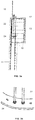
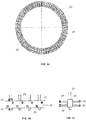
Figure 4a is a cross sectional view of the joining area of a metal segment and a concrete segment of a hollow tower that includes a joining device according to the invention.Figure 4b is a partial perspective view of the bottom of said joining device.Figures 4c, 4d and 4e are, respectively plan, partial side elevation and partial front elevation views of the joining device. - The present invention propose the use of a bolt cage as a joining device of a metal segment to a concrete segment of a hollow tower such as those used to support wind turbines where said segments have a cylindrical and/or frustoconical shape.
- The use of a bolt cage for joining a
metal tower 16 to a foundation is well known (seeFigures 2a and 2b ) being the bolt cage formed by a set ofbolts 22 attached to ananchoring ring 24 bynuts 34 arranged on its both sides. The set ofbolts 22 is arranged in said anchoringring 24 following the traces of two concentric circumferences at a prefixed distance between them. - That bolt cage is installed in the hole of the foundation of the
metal tower 16 leaving the free ends of thebolts 22 protruding from theground plane 12 so that can serve as joining means to thebase 14 of themetal tower 16 together thenuts 36. At a later stage the concreting of the foundation is carried out and the bolt cage is embedded by the concrete. - With that structure, the
bolts 22 transmit both the prestressing forces as the forces that try to open/decompress the steel-concrete joint to the foundation by means of anchoringring 24. - In the case of hybrid towers, the bolt cage solution is potentially interesting for joining a
metal segment 15 with abase 17 to aconcrete segment 11 with awidened area 13 at its edge in contact with themetal segment 15. A direct application of the same (seeFigures 3a and 3b ) shows that: - In the area where it should be located the
anchoring ring 24 there is a high quantity ofreinforcement 19 of the widenedarea 13 in order to bear tensile stresses. - The anchoring
ring 24 needed to transmit the efforts of the bolt cage to the concrete is too large. - The available space in the widened
area 13 is scarce given the need to provide continuity toreinforcement 19. - As a result of this, there is a high probability of interference between the
anchoring ring 24 and thereinforcement 19 that make impractical the applicability of the bolt cage as hinders the correct positioning ofreinforcement 19. - To solve this problem the invention proposes (see
Figures 4a-4e ) a joining device in the form of a bolt cage but with a specific configuration. A set ofbolts 23 is disposed in ananchoring ring 25 following the trace of a circumference at a prefixed distance between them. They are fixed to the anchoringring 25 bynuts 33. The joining device further comprises a set ofconnectors 29 arranged radially on either side of theanchoring ring 25 that complement theanchoring ring 25 as stress transmission means to the concrete by adherence. Theconnectors 29 are preferably configured with a protrudingend 30 to improve their adherence capability to the concrete end. The free ends of thebolts 23 are fixed to thebase 17 of themetal segment 15 bynuts 35. - With this configuration the width of
anchoring ring 25 is reduced avoiding thereby interference with thereinforcement 19. In turn, the reduced width of theanchoring ring 25 provides the necessary space so that thebolts 23 can pass through it facilitating the adjustment between the shapes of theconcrete segment 11 and themetal segment 15. - In the preferred embodiment illustrated in
Figures anchoring ring 25 has a rectangular cross section and theconnectors 29 are arranged alternately at different distances from the top edges to facilitate compatibility with thereinforcement 19. - Although the present invention has been described in connection with various embodiments, it will be appreciated from the specification that various combinations of elements, variations or improvements therein may be made, and are within the scope of the invention as defined by the appended claims.
Claims (10)
- Joining device of a metal segment (15) to a concrete segment (11) of a hollow tower;
the concrete segment (11) comprising a widened area (13) at its end in contact with the metal segment (15) with reinforcement (19);
the metal segment (15) comprising a base (17) arranged to abut on said widened area (13);
the joining device comprising a set of bolts (23) passing through one of its ends by holes of an anchoring ring (25) and attached to both sides of it by a first set of nuts (33) and its other end being arranged to pass through engaging holes of the base (17) of the metal segment (15) and be secured thereto by a second set of nuts (35);
said joining device being arranged to be embedded in the concrete of said widened area (13) except at the ends of the set of bolts (23) intended to be fixed to the base (17) of the metal segment (15);
characterized in that said anchoring ring (25) also comprises a set of connectors (29) which extend externally and internally thereto in a direction substantially perpendicular to bolts (23) and are arranged so as not to interfere with said reinforcement (19). - Joining device according to claim 1, wherein:- the metal segment (15) and the concrete segment (11) have a cylindrical and/or frustoconical shape;- the anchoring ring (25) has a circular shape;- the bolts (23) are located at the same distance from the center of the anchoring ring (25).
- Joining device according to claim 2, wherein said connectors (29) are arranged in radial direction relative to the anchoring ring (25).
- Joining device according to any of claims 1-3, wherein the anchoring ring (25) has a rectangular cross section and said connectors (29) are attached to the side surfaces of the anchoring ring (25) and arranged alternately a different distance from their top edges.
- Joining device according to any of claims 1-4, wherein said connectors (29) are configured with a protruding end (30).
- Hollow tower comprising at least one metal segment (15) joined to a concrete segment (11) by a joining device;
the concrete segment (11) comprising a widened area (13) at its end in contact with the metal segment (15) with reinforcement (19);
the metal segment (15) comprising a base (17) arranged to abut on said widened area (13);
the joining device comprising a set of bolts (23) passing through one of its ends by holes of an anchoring ring (25) and attached to both sides of it by a first set of nuts (33) and its other end being arranged to pass through engaging holes of the base (17) of the metal segment (15) and be secured thereto by a second set of nuts (35);
said joining device being arranged to be embedded in the concrete of said widened area (13) except at the ends of the set of bolts (23) intended to be fixed to the base (17) of the metal segment (15);
characterized in that said anchoring ring (25) also comprises a set of connectors (29) which extend externally and internally thereto in a direction substantially perpendicular to bolts (23) and are arranged so as not to interfere with said reinforcement (19). - Hollow tower according to claim 6, wherein:- the metal segment (15) and the concrete segment (11) have a cylindrical and/or frustoconical shape;- the anchoring ring (25) has a circular shape;- the bolts (23) are located at the same distance from the center of the anchoring ring (25).
- Hollow tower according to claim 7, wherein said connectors (29) are arranged in radial direction relative to the anchoring ring (25).
- Hollow tower according to any of claims 6-8, wherein the anchoring ring (25) has a rectangular cross section and said connectors (29) are attached to the side surfaces of the anchoring ring (25) and arranged alternately a different distance from their top edges.
- Hollow tower according to any of claims 6-9, wherein said connectors (29) are configured with a protruding end (30).
Applications Claiming Priority (2)
| Application Number | Priority Date | Filing Date | Title |
|---|---|---|---|
| ES201500269A ES2589962B1 (en) | 2015-04-17 | 2015-04-17 | Connecting device of a metal section with a concrete section in a hollow hybrid tower |
| PCT/ES2016/000043 WO2016166387A1 (en) | 2015-04-17 | 2016-04-06 | Device for joining a metal section with a concrete section in a hybrid hollow tower |
Publications (3)
| Publication Number | Publication Date |
|---|---|
| EP3306079A1 true EP3306079A1 (en) | 2018-04-11 |
| EP3306079A4 EP3306079A4 (en) | 2019-04-17 |
| EP3306079B1 EP3306079B1 (en) | 2021-05-26 |
Family
ID=57126083
Family Applications (1)
| Application Number | Title | Priority Date | Filing Date |
|---|---|---|---|
| EP16779652.3A Active EP3306079B1 (en) | 2015-04-17 | 2016-04-06 | Device for joining a metal section with a concrete section in a hybrid hollow tower |
Country Status (7)
| Country | Link |
|---|---|
| US (1) | US10704285B2 (en) |
| EP (1) | EP3306079B1 (en) |
| CN (1) | CN107532569B (en) |
| BR (1) | BR112017022351A2 (en) |
| ES (2) | ES2589962B1 (en) |
| MX (1) | MX2017013374A (en) |
| WO (1) | WO2016166387A1 (en) |
Cited By (3)
| Publication number | Priority date | Publication date | Assignee | Title |
|---|---|---|---|---|
| EP4343145A1 (en) * | 2023-06-21 | 2024-03-27 | Nordex Energy Spain, S.A.U. | Set of concrete segments of adjacent sections of a wind turbine tower, and method of assembling a wind turbine |
| EP4345297A1 (en) * | 2022-09-27 | 2024-04-03 | Nordex Energy Spain, S.A.U. | Tower of a wind turbine |
| WO2024068727A1 (en) * | 2022-09-27 | 2024-04-04 | Nordex Energy Se & Co. Kg | Tower of a wind turbine |
Families Citing this family (2)
| Publication number | Priority date | Publication date | Assignee | Title |
|---|---|---|---|---|
| DE102017009984A1 (en) * | 2017-10-26 | 2019-05-02 | Senvion Gmbh | Tower with conical steel adapter elements |
| ES2761748A1 (en) * | 2018-11-19 | 2020-05-20 | Nabrawind Tech Sl | Foundation for a wind turbine tower (Machine-translation by Google Translate, not legally binding) |
Family Cites Families (20)
| Publication number | Priority date | Publication date | Assignee | Title |
|---|---|---|---|---|
| BE350891A (en) * | 1928-04-28 | |||
| JPS5312672B2 (en) * | 1972-11-15 | 1978-05-02 | ||
| US5505033A (en) * | 1988-12-06 | 1996-04-09 | 501 Hitachi Metals Ltd. | Column base structure and connection arrangement |
| US4981005A (en) * | 1989-09-11 | 1991-01-01 | Mcginnis Henry J | Tapered pole and method of making |
| AU742308B2 (en) * | 1999-02-03 | 2001-12-20 | Nippon Pillar Packing Co., Ltd. | Pile foundation structure |
| EP1654460B1 (en) * | 2003-08-09 | 2007-02-14 | General Electric Company | Tower foundation, in particular for a wind energy turbine |
| EP1947328B1 (en) * | 2007-01-18 | 2018-10-24 | GE Renewable Technologies | Joining device for hybrid wind turbine towers |
| DE102007031065B4 (en) * | 2007-06-28 | 2011-05-05 | Nordex Energy Gmbh | Wind turbine tower |
| DE102008029651B3 (en) * | 2008-06-24 | 2010-04-08 | Repower Systems Ag | Tower of a wind turbine |
| JP4242445B1 (en) * | 2008-09-11 | 2009-03-25 | 三井造船株式会社 | Basic structure of tower structure |
| CA2789018C (en) * | 2009-02-04 | 2017-07-04 | Thomas M. Espinosa | Concrete anchor |
| DE102009016893B4 (en) * | 2009-04-08 | 2011-12-08 | Nordex Energy Gmbh | Anchoring component for a wind turbine tower |
| US20110131899A1 (en) * | 2010-04-30 | 2011-06-09 | Stefan Voss | Apparatus and method for producing a concrete foundation |
| DE102010039796A1 (en) * | 2010-06-14 | 2011-12-15 | Max Bögl Bauunternehmung GmbH & Co. KG | Tower with an adapter piece and method of making a tower with an adapter piece |
| US8307593B2 (en) * | 2010-08-18 | 2012-11-13 | General Electric Company | Tower with adapter section |
| DE102011087022A1 (en) * | 2011-11-24 | 2013-05-29 | Wobben Properties Gmbh | Device and method for anchoring a wind energy plant |
| DE102012104508A1 (en) * | 2012-05-24 | 2013-11-28 | Max Bögl Wind AG | Tower structure for use as hybrid tower for e.g. offshore-system, has tower sections' front surfaces facing towards each other and forming connecting point of structure, and leveling device arranged between front surfaces at point |
| DE102012020871A1 (en) * | 2012-10-24 | 2014-04-24 | Repower Systems Se | Composite structure for a pile foundation for anchoring a tower, foundation and jacket for a wind turbine, and wind turbine |
| EP2738322B1 (en) * | 2012-11-29 | 2016-01-20 | Siemens Aktiengesellschaft | Tower structure |
| WO2017040019A1 (en) * | 2015-08-31 | 2017-03-09 | Siemens Energy, Inc. | Tower segment and method utilizing segmented bearing plate |
-
2015
- 2015-04-17 ES ES201500269A patent/ES2589962B1/en not_active Expired - Fee Related
-
2016
- 2016-04-06 ES ES16779652T patent/ES2883640T3/en active Active
- 2016-04-06 MX MX2017013374A patent/MX2017013374A/en unknown
- 2016-04-06 CN CN201680021650.1A patent/CN107532569B/en not_active Expired - Fee Related
- 2016-04-06 EP EP16779652.3A patent/EP3306079B1/en active Active
- 2016-04-06 BR BR112017022351-1A patent/BR112017022351A2/en active Search and Examination
- 2016-04-06 US US15/566,481 patent/US10704285B2/en not_active Expired - Fee Related
- 2016-04-06 WO PCT/ES2016/000043 patent/WO2016166387A1/en not_active Ceased
Cited By (3)
| Publication number | Priority date | Publication date | Assignee | Title |
|---|---|---|---|---|
| EP4345297A1 (en) * | 2022-09-27 | 2024-04-03 | Nordex Energy Spain, S.A.U. | Tower of a wind turbine |
| WO2024068727A1 (en) * | 2022-09-27 | 2024-04-04 | Nordex Energy Se & Co. Kg | Tower of a wind turbine |
| EP4343145A1 (en) * | 2023-06-21 | 2024-03-27 | Nordex Energy Spain, S.A.U. | Set of concrete segments of adjacent sections of a wind turbine tower, and method of assembling a wind turbine |
Also Published As
| Publication number | Publication date |
|---|---|
| US10704285B2 (en) | 2020-07-07 |
| MX2017013374A (en) | 2018-03-07 |
| ES2883640T3 (en) | 2021-12-09 |
| EP3306079A4 (en) | 2019-04-17 |
| US20180320400A1 (en) | 2018-11-08 |
| ES2589962A1 (en) | 2016-11-17 |
| ES2589962B1 (en) | 2017-09-08 |
| CN107532569A (en) | 2018-01-02 |
| WO2016166387A1 (en) | 2016-10-20 |
| BR112017022351A2 (en) | 2018-07-10 |
| EP3306079B1 (en) | 2021-05-26 |
| CN107532569B (en) | 2020-02-11 |
Similar Documents
| Publication | Publication Date | Title |
|---|---|---|
| EP3306079B1 (en) | Device for joining a metal section with a concrete section in a hybrid hollow tower | |
| CN111456909B (en) | Central tube component, central tube having the same, and tower tube foundation | |
| CA2585534C (en) | Tower adapter, method of producing a tower foundation and tower foundation | |
| US7975438B2 (en) | Joining device for hybrid wind turbine towers | |
| EP3467304B1 (en) | Tower section for automatically raising a wind turbine and automatic raising method for same | |
| EP2610488A1 (en) | Wind turbine device and method for constructing tower for blade wheel | |
| JP2007520653A (en) | Wind turbine tower, prefabricated metal wall parts for use in wind turbine tower, and method for constructing wind turbine tower | |
| AU2004238973A1 (en) | Foundation for a wind energy plant | |
| US9175493B2 (en) | Core component and tower assembly for a tower structure | |
| US11028551B2 (en) | Foundation for a tower of a wind-turbine | |
| EP2857614A1 (en) | Concrete tower formed with precast pieces | |
| US20180112371A1 (en) | Wind Turbine Foundation | |
| WO2017215718A1 (en) | A wind turbine tower and a method for erecting a wind turbine tower | |
| EP4400654A1 (en) | Hybrid prefabricated foundation for towers and method of installing a hybrid prefabricated foundation for towers | |
| EP3290692A1 (en) | Wind-turbine tower, wind turbine, and method of assembling wind-turbine tower | |
| KR101358435B1 (en) | Complex section tower combination assembly for wind power generator | |
| EP4345295A1 (en) | Concrete segment of a section of a tower of a wind turbine and adapter of a tower of a wind turbine tower | |
| KR20160060431A (en) | Foundation for Wind Generator and Construction Method Thereof | |
| CN120476255A (en) | Concrete segment of a section of a tower of a wind turbine and tower adapter of a tower of a wind turbine | |
| EP2746578B1 (en) | Segmented tower bottom flange and method of assembly | |
| EP4495327A1 (en) | Positioning device for orienting at least one post-tensioning element in a concrete foundation | |
| CN103527424A (en) | Precast concrete tower of wind generating set | |
| CN111287899A (en) | Anchoring tower barrel section of concrete tower barrel and concrete tower barrel | |
| EP3401445B1 (en) | Anchoring section for a foundation structure | |
| RU2782228C2 (en) | Foundation for wind power plant |
Legal Events
| Date | Code | Title | Description |
|---|---|---|---|
| STAA | Information on the status of an ep patent application or granted ep patent |
Free format text: STATUS: THE INTERNATIONAL PUBLICATION HAS BEEN MADE |
|
| PUAI | Public reference made under article 153(3) epc to a published international application that has entered the european phase |
Free format text: ORIGINAL CODE: 0009012 |
|
| STAA | Information on the status of an ep patent application or granted ep patent |
Free format text: STATUS: REQUEST FOR EXAMINATION WAS MADE |
|
| 17P | Request for examination filed |
Effective date: 20171023 |
|
| AK | Designated contracting states |
Kind code of ref document: A1 Designated state(s): AL AT BE BG CH CY CZ DE DK EE ES FI FR GB GR HR HU IE IS IT LI LT LU LV MC MK MT NL NO PL PT RO RS SE SI SK SM TR |
|
| AX | Request for extension of the european patent |
Extension state: BA ME |
|
| DAV | Request for validation of the european patent (deleted) | ||
| DAX | Request for extension of the european patent (deleted) | ||
| A4 | Supplementary search report drawn up and despatched |
Effective date: 20190320 |
|
| RAP1 | Party data changed (applicant data changed or rights of an application transferred) |
Owner name: SIEMENS GAMESA RENEWABLE ENERGY INNOVATION & TECHN |
|
| RIC1 | Information provided on ipc code assigned before grant |
Ipc: E04H 12/12 20060101ALI20190314BHEP Ipc: E04H 12/02 20060101ALI20190314BHEP Ipc: E04H 12/08 20060101ALI20190314BHEP Ipc: F03D 13/20 20160101AFI20190314BHEP |
|
| STAA | Information on the status of an ep patent application or granted ep patent |
Free format text: STATUS: EXAMINATION IS IN PROGRESS |
|
| 17Q | First examination report despatched |
Effective date: 20200318 |
|
| GRAP | Despatch of communication of intention to grant a patent |
Free format text: ORIGINAL CODE: EPIDOSNIGR1 |
|
| STAA | Information on the status of an ep patent application or granted ep patent |
Free format text: STATUS: GRANT OF PATENT IS INTENDED |
|
| INTG | Intention to grant announced |
Effective date: 20210303 |
|
| GRAS | Grant fee paid |
Free format text: ORIGINAL CODE: EPIDOSNIGR3 |
|
| GRAA | (expected) grant |
Free format text: ORIGINAL CODE: 0009210 |
|
| STAA | Information on the status of an ep patent application or granted ep patent |
Free format text: STATUS: THE PATENT HAS BEEN GRANTED |
|
| AK | Designated contracting states |
Kind code of ref document: B1 Designated state(s): AL AT BE BG CH CY CZ DE DK EE ES FI FR GB GR HR HU IE IS IT LI LT LU LV MC MK MT NL NO PL PT RO RS SE SI SK SM TR |
|
| REG | Reference to a national code |
Ref country code: GB Ref legal event code: FG4D |
|
| REG | Reference to a national code |
Ref country code: CH Ref legal event code: EP |
|
| REG | Reference to a national code |
Ref country code: AT Ref legal event code: REF Ref document number: 1396472 Country of ref document: AT Kind code of ref document: T Effective date: 20210615 |
|
| REG | Reference to a national code |
Ref country code: DE Ref legal event code: R096 Ref document number: 602016058467 Country of ref document: DE |
|
| REG | Reference to a national code |
Ref country code: IE Ref legal event code: FG4D |
|
| REG | Reference to a national code |
Ref country code: LT Ref legal event code: MG9D |
|
| REG | Reference to a national code |
Ref country code: AT Ref legal event code: MK05 Ref document number: 1396472 Country of ref document: AT Kind code of ref document: T Effective date: 20210526 |
|
| PG25 | Lapsed in a contracting state [announced via postgrant information from national office to epo] |
Ref country code: FI Free format text: LAPSE BECAUSE OF FAILURE TO SUBMIT A TRANSLATION OF THE DESCRIPTION OR TO PAY THE FEE WITHIN THE PRESCRIBED TIME-LIMIT Effective date: 20210526 Ref country code: LT Free format text: LAPSE BECAUSE OF FAILURE TO SUBMIT A TRANSLATION OF THE DESCRIPTION OR TO PAY THE FEE WITHIN THE PRESCRIBED TIME-LIMIT Effective date: 20210526 Ref country code: BG Free format text: LAPSE BECAUSE OF FAILURE TO SUBMIT A TRANSLATION OF THE DESCRIPTION OR TO PAY THE FEE WITHIN THE PRESCRIBED TIME-LIMIT Effective date: 20210826 Ref country code: AT Free format text: LAPSE BECAUSE OF FAILURE TO SUBMIT A TRANSLATION OF THE DESCRIPTION OR TO PAY THE FEE WITHIN THE PRESCRIBED TIME-LIMIT Effective date: 20210526 Ref country code: HR Free format text: LAPSE BECAUSE OF FAILURE TO SUBMIT A TRANSLATION OF THE DESCRIPTION OR TO PAY THE FEE WITHIN THE PRESCRIBED TIME-LIMIT Effective date: 20210526 |
|
| REG | Reference to a national code |
Ref country code: NL Ref legal event code: MP Effective date: 20210526 |
|
| PG25 | Lapsed in a contracting state [announced via postgrant information from national office to epo] |
Ref country code: LV Free format text: LAPSE BECAUSE OF FAILURE TO SUBMIT A TRANSLATION OF THE DESCRIPTION OR TO PAY THE FEE WITHIN THE PRESCRIBED TIME-LIMIT Effective date: 20210526 Ref country code: IS Free format text: LAPSE BECAUSE OF FAILURE TO SUBMIT A TRANSLATION OF THE DESCRIPTION OR TO PAY THE FEE WITHIN THE PRESCRIBED TIME-LIMIT Effective date: 20210926 Ref country code: RS Free format text: LAPSE BECAUSE OF FAILURE TO SUBMIT A TRANSLATION OF THE DESCRIPTION OR TO PAY THE FEE WITHIN THE PRESCRIBED TIME-LIMIT Effective date: 20210526 Ref country code: SE Free format text: LAPSE BECAUSE OF FAILURE TO SUBMIT A TRANSLATION OF THE DESCRIPTION OR TO PAY THE FEE WITHIN THE PRESCRIBED TIME-LIMIT Effective date: 20210526 Ref country code: NO Free format text: LAPSE BECAUSE OF FAILURE TO SUBMIT A TRANSLATION OF THE DESCRIPTION OR TO PAY THE FEE WITHIN THE PRESCRIBED TIME-LIMIT Effective date: 20210826 Ref country code: PT Free format text: LAPSE BECAUSE OF FAILURE TO SUBMIT A TRANSLATION OF THE DESCRIPTION OR TO PAY THE FEE WITHIN THE PRESCRIBED TIME-LIMIT Effective date: 20210927 Ref country code: PL Free format text: LAPSE BECAUSE OF FAILURE TO SUBMIT A TRANSLATION OF THE DESCRIPTION OR TO PAY THE FEE WITHIN THE PRESCRIBED TIME-LIMIT Effective date: 20210526 |
|
| REG | Reference to a national code |
Ref country code: ES Ref legal event code: FG2A Ref document number: 2883640 Country of ref document: ES Kind code of ref document: T3 Effective date: 20211209 |
|
| PG25 | Lapsed in a contracting state [announced via postgrant information from national office to epo] |
Ref country code: NL Free format text: LAPSE BECAUSE OF FAILURE TO SUBMIT A TRANSLATION OF THE DESCRIPTION OR TO PAY THE FEE WITHIN THE PRESCRIBED TIME-LIMIT Effective date: 20210526 |
|
| PG25 | Lapsed in a contracting state [announced via postgrant information from national office to epo] |
Ref country code: DK Free format text: LAPSE BECAUSE OF FAILURE TO SUBMIT A TRANSLATION OF THE DESCRIPTION OR TO PAY THE FEE WITHIN THE PRESCRIBED TIME-LIMIT Effective date: 20210526 Ref country code: EE Free format text: LAPSE BECAUSE OF FAILURE TO SUBMIT A TRANSLATION OF THE DESCRIPTION OR TO PAY THE FEE WITHIN THE PRESCRIBED TIME-LIMIT Effective date: 20210526 Ref country code: CZ Free format text: LAPSE BECAUSE OF FAILURE TO SUBMIT A TRANSLATION OF THE DESCRIPTION OR TO PAY THE FEE WITHIN THE PRESCRIBED TIME-LIMIT Effective date: 20210526 Ref country code: SM Free format text: LAPSE BECAUSE OF FAILURE TO SUBMIT A TRANSLATION OF THE DESCRIPTION OR TO PAY THE FEE WITHIN THE PRESCRIBED TIME-LIMIT Effective date: 20210526 Ref country code: SK Free format text: LAPSE BECAUSE OF FAILURE TO SUBMIT A TRANSLATION OF THE DESCRIPTION OR TO PAY THE FEE WITHIN THE PRESCRIBED TIME-LIMIT Effective date: 20210526 Ref country code: RO Free format text: LAPSE BECAUSE OF FAILURE TO SUBMIT A TRANSLATION OF THE DESCRIPTION OR TO PAY THE FEE WITHIN THE PRESCRIBED TIME-LIMIT Effective date: 20210526 |
|
| REG | Reference to a national code |
Ref country code: DE Ref legal event code: R097 Ref document number: 602016058467 Country of ref document: DE |
|
| PLBE | No opposition filed within time limit |
Free format text: ORIGINAL CODE: 0009261 |
|
| STAA | Information on the status of an ep patent application or granted ep patent |
Free format text: STATUS: NO OPPOSITION FILED WITHIN TIME LIMIT |
|
| 26N | No opposition filed |
Effective date: 20220301 |
|
| PG25 | Lapsed in a contracting state [announced via postgrant information from national office to epo] |
Ref country code: IS Free format text: LAPSE BECAUSE OF FAILURE TO SUBMIT A TRANSLATION OF THE DESCRIPTION OR TO PAY THE FEE WITHIN THE PRESCRIBED TIME-LIMIT Effective date: 20210926 Ref country code: AL Free format text: LAPSE BECAUSE OF FAILURE TO SUBMIT A TRANSLATION OF THE DESCRIPTION OR TO PAY THE FEE WITHIN THE PRESCRIBED TIME-LIMIT Effective date: 20210526 |
|
| PG25 | Lapsed in a contracting state [announced via postgrant information from national office to epo] |
Ref country code: IT Free format text: LAPSE BECAUSE OF FAILURE TO SUBMIT A TRANSLATION OF THE DESCRIPTION OR TO PAY THE FEE WITHIN THE PRESCRIBED TIME-LIMIT Effective date: 20210526 |
|
| REG | Reference to a national code |
Ref country code: DE Ref legal event code: R082 Ref document number: 602016058467 Country of ref document: DE Representative=s name: SAUTHOFF, KARSTEN, DIPL.-ING. UNIV., DE |
|
| REG | Reference to a national code |
Ref country code: DE Ref legal event code: R119 Ref document number: 602016058467 Country of ref document: DE |
|
| REG | Reference to a national code |
Ref country code: CH Ref legal event code: PL |
|
| GBPC | Gb: european patent ceased through non-payment of renewal fee |
Effective date: 20220406 |
|
| REG | Reference to a national code |
Ref country code: BE Ref legal event code: MM Effective date: 20220430 |
|
| PG25 | Lapsed in a contracting state [announced via postgrant information from national office to epo] |
Ref country code: MC Free format text: LAPSE BECAUSE OF FAILURE TO SUBMIT A TRANSLATION OF THE DESCRIPTION OR TO PAY THE FEE WITHIN THE PRESCRIBED TIME-LIMIT Effective date: 20210526 Ref country code: LI Free format text: LAPSE BECAUSE OF NON-PAYMENT OF DUE FEES Effective date: 20220430 Ref country code: GB Free format text: LAPSE BECAUSE OF NON-PAYMENT OF DUE FEES Effective date: 20220406 Ref country code: FR Free format text: LAPSE BECAUSE OF NON-PAYMENT OF DUE FEES Effective date: 20220430 Ref country code: DE Free format text: LAPSE BECAUSE OF NON-PAYMENT OF DUE FEES Effective date: 20221103 Ref country code: CH Free format text: LAPSE BECAUSE OF NON-PAYMENT OF DUE FEES Effective date: 20220430 Ref country code: LU Free format text: LAPSE BECAUSE OF NON-PAYMENT OF DUE FEES Effective date: 20220406 |
|
| PG25 | Lapsed in a contracting state [announced via postgrant information from national office to epo] |
Ref country code: BE Free format text: LAPSE BECAUSE OF NON-PAYMENT OF DUE FEES Effective date: 20220430 |
|
| PG25 | Lapsed in a contracting state [announced via postgrant information from national office to epo] |
Ref country code: IE Free format text: LAPSE BECAUSE OF NON-PAYMENT OF DUE FEES Effective date: 20220406 |
|
| REG | Reference to a national code |
Ref country code: ES Ref legal event code: FD2A Effective date: 20230526 |
|
| PG25 | Lapsed in a contracting state [announced via postgrant information from national office to epo] |
Ref country code: ES Free format text: LAPSE BECAUSE OF NON-PAYMENT OF DUE FEES Effective date: 20220407 |
|
| PG25 | Lapsed in a contracting state [announced via postgrant information from national office to epo] |
Ref country code: HU Free format text: LAPSE BECAUSE OF FAILURE TO SUBMIT A TRANSLATION OF THE DESCRIPTION OR TO PAY THE FEE WITHIN THE PRESCRIBED TIME-LIMIT; INVALID AB INITIO Effective date: 20160406 |
|
| PG25 | Lapsed in a contracting state [announced via postgrant information from national office to epo] |
Ref country code: MK Free format text: LAPSE BECAUSE OF FAILURE TO SUBMIT A TRANSLATION OF THE DESCRIPTION OR TO PAY THE FEE WITHIN THE PRESCRIBED TIME-LIMIT Effective date: 20210526 Ref country code: CY Free format text: LAPSE BECAUSE OF FAILURE TO SUBMIT A TRANSLATION OF THE DESCRIPTION OR TO PAY THE FEE WITHIN THE PRESCRIBED TIME-LIMIT Effective date: 20210526 |
|
| PG25 | Lapsed in a contracting state [announced via postgrant information from national office to epo] |
Ref country code: TR Free format text: LAPSE BECAUSE OF FAILURE TO SUBMIT A TRANSLATION OF THE DESCRIPTION OR TO PAY THE FEE WITHIN THE PRESCRIBED TIME-LIMIT Effective date: 20210526 |
|
| PG25 | Lapsed in a contracting state [announced via postgrant information from national office to epo] |
Ref country code: MT Free format text: LAPSE BECAUSE OF FAILURE TO SUBMIT A TRANSLATION OF THE DESCRIPTION OR TO PAY THE FEE WITHIN THE PRESCRIBED TIME-LIMIT Effective date: 20210526 |
|
| PG25 | Lapsed in a contracting state [announced via postgrant information from national office to epo] |
Ref country code: GR Free format text: LAPSE BECAUSE OF NON-PAYMENT OF DUE FEES Effective date: 20210526 |
|
| PG25 | Lapsed in a contracting state [announced via postgrant information from national office to epo] |
Ref country code: GR Free format text: LAPSE BECAUSE OF NON-PAYMENT OF DUE FEES Effective date: 20210526 |