EP3306039A1 - Stator assembly for a gas turbine engine - Google Patents
Stator assembly for a gas turbine engine Download PDFInfo
- Publication number
- EP3306039A1 EP3306039A1 EP17191260.3A EP17191260A EP3306039A1 EP 3306039 A1 EP3306039 A1 EP 3306039A1 EP 17191260 A EP17191260 A EP 17191260A EP 3306039 A1 EP3306039 A1 EP 3306039A1
- Authority
- EP
- European Patent Office
- Prior art keywords
- slot
- platform
- stator assembly
- region
- parallel
- Prior art date
- Legal status (The legal status is an assumption and is not a legal conclusion. Google has not performed a legal analysis and makes no representation as to the accuracy of the status listed.)
- Granted
Links
Images


Classifications
-
- F—MECHANICAL ENGINEERING; LIGHTING; HEATING; WEAPONS; BLASTING
- F01—MACHINES OR ENGINES IN GENERAL; ENGINE PLANTS IN GENERAL; STEAM ENGINES
- F01D—NON-POSITIVE DISPLACEMENT MACHINES OR ENGINES, e.g. STEAM TURBINES
- F01D9/00—Stators
- F01D9/02—Nozzles; Nozzle boxes; Stator blades; Guide conduits, e.g. individual nozzles
- F01D9/04—Nozzles; Nozzle boxes; Stator blades; Guide conduits, e.g. individual nozzles forming ring or sector
- F01D9/042—Nozzles; Nozzle boxes; Stator blades; Guide conduits, e.g. individual nozzles forming ring or sector fixing blades to stators
- F01D9/044—Nozzles; Nozzle boxes; Stator blades; Guide conduits, e.g. individual nozzles forming ring or sector fixing blades to stators permanently, e.g. by welding, brazing, casting or the like
-
- F—MECHANICAL ENGINEERING; LIGHTING; HEATING; WEAPONS; BLASTING
- F01—MACHINES OR ENGINES IN GENERAL; ENGINE PLANTS IN GENERAL; STEAM ENGINES
- F01D—NON-POSITIVE DISPLACEMENT MACHINES OR ENGINES, e.g. STEAM TURBINES
- F01D5/00—Blades; Blade-carrying members; Heating, heat-insulating, cooling or antivibration means on the blades or the members
- F01D5/02—Blade-carrying members, e.g. rotors
- F01D5/08—Heating, heat-insulating or cooling means
- F01D5/081—Cooling fluid being directed on the side of the rotor disc or at the roots of the blades
-
- F—MECHANICAL ENGINEERING; LIGHTING; HEATING; WEAPONS; BLASTING
- F01—MACHINES OR ENGINES IN GENERAL; ENGINE PLANTS IN GENERAL; STEAM ENGINES
- F01D—NON-POSITIVE DISPLACEMENT MACHINES OR ENGINES, e.g. STEAM TURBINES
- F01D5/00—Blades; Blade-carrying members; Heating, heat-insulating, cooling or antivibration means on the blades or the members
- F01D5/30—Fixing blades to rotors; Blade roots ; Blade spacers
- F01D5/3023—Fixing blades to rotors; Blade roots ; Blade spacers of radial insertion type, e.g. in individual recesses
- F01D5/303—Fixing blades to rotors; Blade roots ; Blade spacers of radial insertion type, e.g. in individual recesses in a circumferential slot
-
- F—MECHANICAL ENGINEERING; LIGHTING; HEATING; WEAPONS; BLASTING
- F01—MACHINES OR ENGINES IN GENERAL; ENGINE PLANTS IN GENERAL; STEAM ENGINES
- F01D—NON-POSITIVE DISPLACEMENT MACHINES OR ENGINES, e.g. STEAM TURBINES
- F01D5/00—Blades; Blade-carrying members; Heating, heat-insulating, cooling or antivibration means on the blades or the members
- F01D5/30—Fixing blades to rotors; Blade roots ; Blade spacers
- F01D5/3061—Fixing blades to rotors; Blade roots ; Blade spacers by welding, brazing
-
- F—MECHANICAL ENGINEERING; LIGHTING; HEATING; WEAPONS; BLASTING
- F05—INDEXING SCHEMES RELATING TO ENGINES OR PUMPS IN VARIOUS SUBCLASSES OF CLASSES F01-F04
- F05D—INDEXING SCHEME FOR ASPECTS RELATING TO NON-POSITIVE-DISPLACEMENT MACHINES OR ENGINES, GAS-TURBINES OR JET-PROPULSION PLANTS
- F05D2230/00—Manufacture
- F05D2230/20—Manufacture essentially without removing material
- F05D2230/23—Manufacture essentially without removing material by permanently joining parts together
- F05D2230/232—Manufacture essentially without removing material by permanently joining parts together by welding
- F05D2230/237—Brazing
-
- F—MECHANICAL ENGINEERING; LIGHTING; HEATING; WEAPONS; BLASTING
- F05—INDEXING SCHEMES RELATING TO ENGINES OR PUMPS IN VARIOUS SUBCLASSES OF CLASSES F01-F04
- F05D—INDEXING SCHEME FOR ASPECTS RELATING TO NON-POSITIVE-DISPLACEMENT MACHINES OR ENGINES, GAS-TURBINES OR JET-PROPULSION PLANTS
- F05D2230/00—Manufacture
- F05D2230/60—Assembly methods
- F05D2230/64—Assembly methods using positioning or alignment devices for aligning or centring, e.g. pins
-
- F—MECHANICAL ENGINEERING; LIGHTING; HEATING; WEAPONS; BLASTING
- F05—INDEXING SCHEMES RELATING TO ENGINES OR PUMPS IN VARIOUS SUBCLASSES OF CLASSES F01-F04
- F05D—INDEXING SCHEME FOR ASPECTS RELATING TO NON-POSITIVE-DISPLACEMENT MACHINES OR ENGINES, GAS-TURBINES OR JET-PROPULSION PLANTS
- F05D2240/00—Components
- F05D2240/10—Stators
-
- F—MECHANICAL ENGINEERING; LIGHTING; HEATING; WEAPONS; BLASTING
- F05—INDEXING SCHEMES RELATING TO ENGINES OR PUMPS IN VARIOUS SUBCLASSES OF CLASSES F01-F04
- F05D—INDEXING SCHEME FOR ASPECTS RELATING TO NON-POSITIVE-DISPLACEMENT MACHINES OR ENGINES, GAS-TURBINES OR JET-PROPULSION PLANTS
- F05D2240/00—Components
- F05D2240/10—Stators
- F05D2240/12—Fluid guiding means, e.g. vanes
-
- F—MECHANICAL ENGINEERING; LIGHTING; HEATING; WEAPONS; BLASTING
- F05—INDEXING SCHEMES RELATING TO ENGINES OR PUMPS IN VARIOUS SUBCLASSES OF CLASSES F01-F04
- F05D—INDEXING SCHEME FOR ASPECTS RELATING TO NON-POSITIVE-DISPLACEMENT MACHINES OR ENGINES, GAS-TURBINES OR JET-PROPULSION PLANTS
- F05D2240/00—Components
- F05D2240/80—Platforms for stationary or moving blades
- F05D2240/81—Cooled platforms
-
- F—MECHANICAL ENGINEERING; LIGHTING; HEATING; WEAPONS; BLASTING
- F05—INDEXING SCHEMES RELATING TO ENGINES OR PUMPS IN VARIOUS SUBCLASSES OF CLASSES F01-F04
- F05D—INDEXING SCHEME FOR ASPECTS RELATING TO NON-POSITIVE-DISPLACEMENT MACHINES OR ENGINES, GAS-TURBINES OR JET-PROPULSION PLANTS
- F05D2260/00—Function
- F05D2260/30—Retaining components in desired mutual position
Definitions
- the present invention provides a stator assembly comprising at least one annular platform defining a boundary of an annulus and a plurality of guide vanes for arranging in a circumferential array on the annular platform; the platform including a circumferential array of slots, each slot at a first end converging from an annulus facing side to an opposite side of the platform and then extending parallel towards a second end; one or more cooling holes arranged in a wall of the slot; each vane including a root portion which converges from a first region distal to the root end and then extends parallel towards the root end, the root portion configured to engage in a slot of the platform with the convergent portion abutting a convergent wall portion of the slot and the parallel portion spaced from the parallel wall of the slot; and at least one bore in a parallel wall of each slot and at least one bore in the parallel section of the root portion, the bore of parallel wall of the slot and the bore of the parallel section of the root portion positioned to align when a vane is engaged in a
- two or more sets of aligning bores are provided in the root portion and slot wall. These remove the need for an additional drilling operation when repairing a joint.
- a pin 13 is located in the aligned bores 12a, 12b to mechanically lock the vane 2 into the slot.
- a braze joint 14 extends from an end of the space 10 towards but not as far as the aligned holes 11 a, 11 b. Cooling air delivered through cooling hole 5 is able to circulate through the reduced space and assists in keeping the braze joint 14 cool avoiding a possible loss in joint integrity when exposed to excessive heat.
- FIG. 2 shows the assembly just after the braze 14 has been removed. As can be seen, a new pin 213 is located in the previously vacant aligned bores 11 a, 11 b. The parallel portion 9 of the root 7 now extends beyond the shortened parallel wall 4 of the slot. A new braze joint 214 is provided in the remaining space 10.
- FIG 3 shows a schematic of a stator made from an assembly in accordance with the invention.
- the stator comprises a first, radially inner annular platform 30 and a second, radially outer annular platform 31.
- the platforms are radially and co-axially aligned on a centre C and are separated by an annular space 32.
- a plurality of vanes 33 is arranged in a circumferential array around the platforms 31, 32 and bridges the annular space 32.
- a gas turbine engine is generally indicated at 400, having a principal and rotational axis 41.
- the engine 400 comprises, in axial flow series, an air intake 42, a propulsive fan 43, a high-pressure compressor 44, combustion equipment 45, a high-pressure turbine 46, a low-pressure turbine 47 and an exhaust nozzle 48.
- a nacelle 50 generally surrounds the engine 400 and defines the intake 42.
- the gas turbine engine 400 works in the conventional manner so that air entering the intake 42 is accelerated by the fan 43 to produce two air flows: a first air flow into the high-pressure compressor 44 and a second air flow which passes through a bypass duct 51 to provide propulsive thrust.
- the high-pressure compressor 44 compresses the air flow directed into it before delivering that air to the combustion equipment 45.
- the air flow is mixed with fuel and the mixture combusted.
- the resultant hot combustion products then expand through, and thereby drive the high and low-pressure turbines 46, 47 before being exhausted through the nozzle 48 to provide additional propulsive thrust.
- the high 46 and low 47 pressure turbines drive respectively the high pressure compressor 44 and the fan 43, each by suitable interconnecting shaft.
- a stator assembly in accordance with the invention may be incorporated in either of the turbine stages 46, 47.
- gas turbine engines to which the present disclosure may be applied may have alternative configurations.
- such engines may have an alternative number of interconnecting shafts (e.g. three) and/or an alternative number of compressors and/or turbines.
- the engine may comprise a gearbox provided in the drive train from a turbine to a compressor and/or fan.
Landscapes
- Engineering & Computer Science (AREA)
- Mechanical Engineering (AREA)
- General Engineering & Computer Science (AREA)
- Turbine Rotor Nozzle Sealing (AREA)
Abstract
Description
- The present invention relates to the joining of nozzle guide vanes of a turbine stator to a platform. More particularly the invention relates to joint arrangements which facilitate replacement of vanes joined to a platform.
- A turbine stage consists of a rotor and a stator. In a rotor, a circumferential array of aerofoil blades is provided around a circumferential platform of a disc. The disc is mounted for rotation on a rotor shaft. The stator sits adjacent the rotor, upstream of the rotor, and typically comprises a pair of annular platforms in radial and concentric alignment, one platform having a greater diameter than the other. A circumferential array of guide vanes is provided to bridge an annular space between the annular platforms. Adjacent guide vanes form nozzles which serve to accelerate a working fluid towards the rotor.
- It is known to join guide vanes to the annular platforms by brazing at junctions within the annular space, the annular space coinciding with an annulus through which the working fluid for the turbine is directed. Such joints are exposed to extreme temperatures and consequently may require shielding or cooling. Where such joints fail, their location within the annulus presents difficulties in accessing and repairing.
- The present invention provides a stator assembly comprising at least one annular platform defining a boundary of an annulus and a plurality of guide vanes for arranging in a circumferential array on the annular platform;
the platform including a circumferential array of slots, each slot at a first end converging from an annulus facing side to an opposite side of the platform and then extending parallel towards a second end;
one or more cooling holes arranged in a wall of the slot;
each vane including a root portion which converges from a first region distal to the root end and then extends parallel towards the root end, the root portion configured to engage in a slot of the platform with the convergent portion abutting a convergent wall portion of the slot and the parallel portion spaced from the parallel wall of the slot; and
at least one bore in a parallel wall of each slot and at least one bore in the parallel section of the root portion, the bore of parallel wall of the slot and the bore of the parallel section of the root portion positioned to align when a vane is engaged in a slot, the aligned bores together configured to receive a pin. - A braze joint may be provided between parallel walls of the root portion and the slot to secure the vane. The braze joint is preferably located adjacent the root end of the vane and extends only partly along the parallel portion. This presents an opportunity to machine off the brazed portion, a new braze joint may be provided on the remaining part of the parallel portion. A new bore may be drilled into the remaining parallel wall of the slot and parallel section of the root portion to accommodate a pin.
- Optionally two or more sets of aligning bores are provided in the root portion and slot wall. These remove the need for an additional drilling operation when repairing a joint.
- The assembly may comprise two annular platforms for arranging in radial and concentric alignment, one platform having a greater diameter than the other so as to define radially inner and outer walls of the annulus. Vanes may comprise a root portion at both ends allowing the vane to engage in both annular platforms whereby to bridge the annulus.
- An embodiment of the invention will now be described with reference to the accompanying figures in which;
-
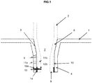
Figure 1 illustrates an assembly in accordance with an embodiment of the invention; -
Figure 2 illustrates the embodiment ofFigure 1 after repair; -
Figure 3 illustrates a stator of a turbine stage showing positioning of components of the assembly; -
Figure 4 illustrates a gas turbine engine in which a stator assembly in accordance with the invention might usefully be employed. - As can be seen in
Figure 1 aplatform 1 includes a slot for receiving avane 2. Walls of the slot converge in afirst region 3 and extend in parallel in asecond region 4. Acooling hole 5 passes through theparallel wall 4 of the slot. Thevane 2 has aroot portion 7 which includes a convergingportion 8 and aparallel portion 9. Theconverging portion 8 abuts the converging walls of thefirst region 3 of the slot and theparallel portion 9 extends into the parallel second region of the slot leaving asmall space 10 between the parallel portion of the root and theparallel wall 4 of the slot. Two pairs of alignedbores pin 13 is located in the alignedbores vane 2 into the slot. Abraze joint 14 extends from an end of thespace 10 towards but not as far as the alignedholes cooling hole 5 is able to circulate through the reduced space and assists in keeping thebraze joint 14 cool avoiding a possible loss in joint integrity when exposed to excessive heat. - If the
braze joint 14 is damaged, thejoint 14 can be conveniently removed by machining off an end of the parallel section of the slot.Figure 2 shows the assembly just after thebraze 14 has been removed. As can be seen, anew pin 213 is located in the previously vacant alignedbores parallel portion 9 of theroot 7 now extends beyond the shortenedparallel wall 4 of the slot. Anew braze joint 214 is provided in theremaining space 10. -
Figure 3 shows a schematic of a stator made from an assembly in accordance with the invention. As can be seen, the stator comprises a first, radially innerannular platform 30 and a second, radially outerannular platform 31. The platforms are radially and co-axially aligned on a centre C and are separated by anannular space 32. A plurality ofvanes 33 is arranged in a circumferential array around theplatforms annular space 32. - With reference to
Figure 4 , a gas turbine engine is generally indicated at 400, having a principal androtational axis 41. Theengine 400 comprises, in axial flow series, anair intake 42, apropulsive fan 43, a high-pressure compressor 44,combustion equipment 45, a high-pressure turbine 46, a low-pressure turbine 47 and anexhaust nozzle 48. Anacelle 50 generally surrounds theengine 400 and defines theintake 42. - The
gas turbine engine 400 works in the conventional manner so that air entering theintake 42 is accelerated by thefan 43 to produce two air flows: a first air flow into the high-pressure compressor 44 and a second air flow which passes through abypass duct 51 to provide propulsive thrust. The high-pressure compressor 44 compresses the air flow directed into it before delivering that air to thecombustion equipment 45. - In the
combustion equipment 45 the air flow is mixed with fuel and the mixture combusted. The resultant hot combustion products then expand through, and thereby drive the high and low-pressure turbines nozzle 48 to provide additional propulsive thrust. The high 46 and low 47 pressure turbines drive respectively thehigh pressure compressor 44 and thefan 43, each by suitable interconnecting shaft. - A stator assembly in accordance with the invention may be incorporated in either of the
turbine stages - Other gas turbine engines to which the present disclosure may be applied may have alternative configurations. By way of example such engines may have an alternative number of interconnecting shafts (e.g. three) and/or an alternative number of compressors and/or turbines. Further the engine may comprise a gearbox provided in the drive train from a turbine to a compressor and/or fan.
- It will be understood that the invention is not limited to the embodiments above-described and various modifications and improvements can be made without departing from the concepts described herein. Except where mutually exclusive, any of the features may be employed separately or in combination with any other features and the disclosure extends to and includes all combinations and subcombinations of one or more features described herein.
Claims (8)
- A stator assembly comprising at least one annular platform (1; 30, 31) defining a boundary of an annulus (32) and a plurality of guide vanes (2; 33) for arranging in a circumferential array on the annular platform (1; 30, 31);
the platform (1; 30, 31) including a circumferential array of slots each slot at a first end having walls converging (3) from an annulus facing side to an opposite side of the platform and then extending parallel (4) towards a second end;
one or more cooling holes (5) arranged in a wall (3,4) of the slot;
each vane (2; 33) including a root portion (7) which converges in a first region (8) distal to the root end and then extends parallel towards the root end in a second region (9), the root portion (7) configured to engage in a slot of the platform (1; 30, 31) with the first region (8) abutting a convergent wall portion (3) of the slot and the second region (9) spaced from a parallel wall (4) of the slot; and
at least one bore (11 a, 12a) in a parallel wall (4) of each slot and at least one bore (11 b, 12b) in the second region of the root portion (7), the bores (11 a, 11 b; 12a, 12b) positioned to align when a vane (2) is engaged in a slot, the aligning bores (11 a, 11 b; 12a, 12b) together configured to receive a pin (13). - A stator assembly as claimed in claim 1 wherein a braze joint (14) is provided between parallel walls (4, 9) of the root portion and the slot to secure the vane.
- A stator assembly as claimed in claim 1 or claim 2 comprising two annular platforms (30, 31) for arranging in radial and concentric alignment, one platform having a greater diameter than the other so as to define radially inner and outer walls of the annulus (32) and wherein the vanes (33) include a root portion (7) at both ends.
- A stator assembly as claimed in any preceding claim wherein two or more sets of aligning bores (11 a, 11b; 12a, 12b) are provided in the root portion and slot walls (9, 4).
- A stator vane configured for use in a stator assembly, the stator assembly being as described in any preceding claim.
- An annular platform configured for use in a stator assembly, the stator assembly being as described in any preceding claim.
- A turbine stage comprising an assembled stator assembly as claimed in any of claims 1 to 4 aligned coaxially with a turbine rotor.
- A gas turbine engine comprising one or more turbine stages having the configuration set forth in claim 7.
Applications Claiming Priority (1)
| Application Number | Priority Date | Filing Date | Title |
|---|---|---|---|
| GBGB1616969.0A GB201616969D0 (en) | 2016-10-06 | 2016-10-06 | Stator assembly for a gas turbine engine |
Publications (2)
| Publication Number | Publication Date |
|---|---|
| EP3306039A1 true EP3306039A1 (en) | 2018-04-11 |
| EP3306039B1 EP3306039B1 (en) | 2019-02-06 |
Family
ID=57610722
Family Applications (1)
| Application Number | Title | Priority Date | Filing Date |
|---|---|---|---|
| EP17191260.3A Not-in-force EP3306039B1 (en) | 2016-10-06 | 2017-09-15 | Stator assembly for a gas turbine engine |
Country Status (3)
| Country | Link |
|---|---|
| US (1) | US10337342B2 (en) |
| EP (1) | EP3306039B1 (en) |
| GB (1) | GB201616969D0 (en) |
Families Citing this family (3)
| Publication number | Priority date | Publication date | Assignee | Title |
|---|---|---|---|---|
| US11952918B2 (en) | 2022-07-20 | 2024-04-09 | Ge Infrastructure Technology Llc | Cooling circuit for a stator vane braze joint |
| US20240175367A1 (en) * | 2022-11-29 | 2024-05-30 | Rtx Corporation | Gas turbine engine static vane clusters |
| US12129771B1 (en) * | 2023-08-22 | 2024-10-29 | Ge Infrastructure Technology Llc | Stator vane assembly having mechanical retention device |
Citations (3)
| Publication number | Priority date | Publication date | Assignee | Title |
|---|---|---|---|---|
| US5332360A (en) * | 1993-09-08 | 1994-07-26 | General Electric Company | Stator vane having reinforced braze joint |
| US20160177749A1 (en) * | 2014-12-19 | 2016-06-23 | Alstom Technology Ltd | Blading member for a fluid flow machine |
| WO2016121163A1 (en) * | 2015-01-27 | 2016-08-04 | 三菱重工業株式会社 | Turbine blade, turbine, and method for manufacturing turbine blade |
Family Cites Families (8)
| Publication number | Priority date | Publication date | Assignee | Title |
|---|---|---|---|---|
| US20090110552A1 (en) * | 2007-10-31 | 2009-04-30 | Anderson Rodger O | Compressor stator vane repair with pin |
| EP2594743A1 (en) * | 2011-11-21 | 2013-05-22 | Siemens Aktiengesellschaft | Eccentric diaphragm adjusting pins for a gas turbine engine |
| US8899914B2 (en) | 2012-01-05 | 2014-12-02 | United Technologies Corporation | Stator vane integrated attachment liner and spring damper |
| US9255483B2 (en) | 2012-11-05 | 2016-02-09 | General Electric Company | Locking blade for a rotor |
| KR20140063474A (en) * | 2012-11-16 | 2014-05-27 | 에이비비 터보 시스템즈 아게 | Nozzle ring |
| EP2952688A1 (en) * | 2014-06-02 | 2015-12-09 | Siemens Aktiengesellschaft | Method for assembling a stator stage of a gas turbine engine |
| DE102016201766A1 (en) * | 2016-02-05 | 2017-08-10 | MTU Aero Engines AG | Guide vane system for a turbomachine |
| FR3064682B1 (en) * | 2017-03-31 | 2019-06-14 | Safran Aircraft Engines | INTERMEDIATE CASE FOR AIRCRAFT TURBOMACHINE COMPRISING A LUBRICANT PASSING BIT CONNECTED TO A CARTER BOLT BY A CONNECTING PART |
-
2016
- 2016-10-06 GB GBGB1616969.0A patent/GB201616969D0/en not_active Ceased
-
2017
- 2017-09-15 US US15/705,804 patent/US10337342B2/en not_active Expired - Fee Related
- 2017-09-15 EP EP17191260.3A patent/EP3306039B1/en not_active Not-in-force
Patent Citations (3)
| Publication number | Priority date | Publication date | Assignee | Title |
|---|---|---|---|---|
| US5332360A (en) * | 1993-09-08 | 1994-07-26 | General Electric Company | Stator vane having reinforced braze joint |
| US20160177749A1 (en) * | 2014-12-19 | 2016-06-23 | Alstom Technology Ltd | Blading member for a fluid flow machine |
| WO2016121163A1 (en) * | 2015-01-27 | 2016-08-04 | 三菱重工業株式会社 | Turbine blade, turbine, and method for manufacturing turbine blade |
Also Published As
| Publication number | Publication date |
|---|---|
| GB201616969D0 (en) | 2016-11-23 |
| US20180100403A1 (en) | 2018-04-12 |
| US10337342B2 (en) | 2019-07-02 |
| EP3306039B1 (en) | 2019-02-06 |
Similar Documents
| Publication | Publication Date | Title |
|---|---|---|
| US9115597B2 (en) | Gas turbine engine turbine vane airfoil profile | |
| US20180328187A1 (en) | Turbine engine with an airfoil and insert | |
| CN107435561B (en) | System for cooling seal rails of tip shroud of turbine blade | |
| US10767498B2 (en) | Turbine disk with pinned platforms | |
| US20170306768A1 (en) | Turbine engine shroud assembly | |
| EP3306039B1 (en) | Stator assembly for a gas turbine engine | |
| EP3527784B1 (en) | Gas turbine engine with a coolable vane | |
| EP3170988A1 (en) | Rotor for gas turbine engine | |
| US10689988B2 (en) | Disk lug impingement for gas turbine engine airfoil | |
| EP3144475A1 (en) | Thermal shielding in a gas turbine | |
| US11015464B2 (en) | Conformal seal and vane bow wave cooling | |
| EP3225785A2 (en) | Spline seal for a gas turbine engine | |
| US10774679B2 (en) | Turbine engine airfoil assembly | |
| EP3418496A2 (en) | A rotor blade for a turbomachine | |
| EP3208419A1 (en) | Connection of rotatable parts of a gas turbine engine | |
| EP2952682A1 (en) | Airfoil for a gas turbine engine with a cooled platform | |
| US10753368B2 (en) | Multi-piece non-linear airfoil | |
| US10697313B2 (en) | Turbine engine component with an insert | |
| US20190390557A1 (en) | Turbine wheel assembly with ceramic matrix composite components | |
| US11236625B2 (en) | Method of making a cooled airfoil assembly for a turbine engine | |
| EP3203026B1 (en) | Gas turbine blade with pedestal array | |
| US10001134B2 (en) | Rotor disc | |
| CN116181418A (en) | Gas turbine engine including rotating blade assembly | |
| GB2558758A (en) | A gas turbine engine | |
| BR102016030923A2 (en) | TURBOFAN COMPOST AND STEEL PAD ASSEMBLY |
Legal Events
| Date | Code | Title | Description |
|---|---|---|---|
| PUAI | Public reference made under article 153(3) epc to a published international application that has entered the european phase |
Free format text: ORIGINAL CODE: 0009012 |
|
| STAA | Information on the status of an ep patent application or granted ep patent |
Free format text: STATUS: THE APPLICATION HAS BEEN PUBLISHED |
|
| AK | Designated contracting states |
Kind code of ref document: A1 Designated state(s): AL AT BE BG CH CY CZ DE DK EE ES FI FR GB GR HR HU IE IS IT LI LT LU LV MC MK MT NL NO PL PT RO RS SE SI SK SM TR |
|
| AX | Request for extension of the european patent |
Extension state: BA ME |
|
| STAA | Information on the status of an ep patent application or granted ep patent |
Free format text: STATUS: REQUEST FOR EXAMINATION WAS MADE |
|
| 17P | Request for examination filed |
Effective date: 20181003 |
|
| RBV | Designated contracting states (corrected) |
Designated state(s): AL AT BE BG CH CY CZ DE DK EE ES FI FR GB GR HR HU IE IS IT LI LT LU LV MC MK MT NL NO PL PT RO RS SE SI SK SM TR |
|
| GRAP | Despatch of communication of intention to grant a patent |
Free format text: ORIGINAL CODE: EPIDOSNIGR1 |
|
| STAA | Information on the status of an ep patent application or granted ep patent |
Free format text: STATUS: GRANT OF PATENT IS INTENDED |
|
| GRAS | Grant fee paid |
Free format text: ORIGINAL CODE: EPIDOSNIGR3 |
|
| RIC1 | Information provided on ipc code assigned before grant |
Ipc: F01D 9/04 20060101AFI20181114BHEP |
|
| INTG | Intention to grant announced |
Effective date: 20181205 |
|
| GRAA | (expected) grant |
Free format text: ORIGINAL CODE: 0009210 |
|
| STAA | Information on the status of an ep patent application or granted ep patent |
Free format text: STATUS: THE PATENT HAS BEEN GRANTED |
|
| AK | Designated contracting states |
Kind code of ref document: B1 Designated state(s): AL AT BE BG CH CY CZ DE DK EE ES FI FR GB GR HR HU IE IS IT LI LT LU LV MC MK MT NL NO PL PT RO RS SE SI SK SM TR |
|
| REG | Reference to a national code |
Ref country code: GB Ref legal event code: FG4D |
|
| REG | Reference to a national code |
Ref country code: CH Ref legal event code: EP Ref country code: AT Ref legal event code: REF Ref document number: 1095050 Country of ref document: AT Kind code of ref document: T Effective date: 20190215 |
|
| REG | Reference to a national code |
Ref country code: IE Ref legal event code: FG4D |
|
| REG | Reference to a national code |
Ref country code: DE Ref legal event code: R096 Ref document number: 602017002081 Country of ref document: DE |
|
| REG | Reference to a national code |
Ref country code: NL Ref legal event code: MP Effective date: 20190206 |
|
| REG | Reference to a national code |
Ref country code: LT Ref legal event code: MG4D |
|
| PG25 | Lapsed in a contracting state [announced via postgrant information from national office to epo] |
Ref country code: LT Free format text: LAPSE BECAUSE OF FAILURE TO SUBMIT A TRANSLATION OF THE DESCRIPTION OR TO PAY THE FEE WITHIN THE PRESCRIBED TIME-LIMIT Effective date: 20190206 Ref country code: SE Free format text: LAPSE BECAUSE OF FAILURE TO SUBMIT A TRANSLATION OF THE DESCRIPTION OR TO PAY THE FEE WITHIN THE PRESCRIBED TIME-LIMIT Effective date: 20190206 Ref country code: FI Free format text: LAPSE BECAUSE OF FAILURE TO SUBMIT A TRANSLATION OF THE DESCRIPTION OR TO PAY THE FEE WITHIN THE PRESCRIBED TIME-LIMIT Effective date: 20190206 Ref country code: NO Free format text: LAPSE BECAUSE OF FAILURE TO SUBMIT A TRANSLATION OF THE DESCRIPTION OR TO PAY THE FEE WITHIN THE PRESCRIBED TIME-LIMIT Effective date: 20190506 Ref country code: PT Free format text: LAPSE BECAUSE OF FAILURE TO SUBMIT A TRANSLATION OF THE DESCRIPTION OR TO PAY THE FEE WITHIN THE PRESCRIBED TIME-LIMIT Effective date: 20190606 Ref country code: NL Free format text: LAPSE BECAUSE OF FAILURE TO SUBMIT A TRANSLATION OF THE DESCRIPTION OR TO PAY THE FEE WITHIN THE PRESCRIBED TIME-LIMIT Effective date: 20190206 |
|
| REG | Reference to a national code |
Ref country code: AT Ref legal event code: MK05 Ref document number: 1095050 Country of ref document: AT Kind code of ref document: T Effective date: 20190206 |
|
| PG25 | Lapsed in a contracting state [announced via postgrant information from national office to epo] |
Ref country code: RS Free format text: LAPSE BECAUSE OF FAILURE TO SUBMIT A TRANSLATION OF THE DESCRIPTION OR TO PAY THE FEE WITHIN THE PRESCRIBED TIME-LIMIT Effective date: 20190206 Ref country code: IS Free format text: LAPSE BECAUSE OF FAILURE TO SUBMIT A TRANSLATION OF THE DESCRIPTION OR TO PAY THE FEE WITHIN THE PRESCRIBED TIME-LIMIT Effective date: 20190606 Ref country code: LV Free format text: LAPSE BECAUSE OF FAILURE TO SUBMIT A TRANSLATION OF THE DESCRIPTION OR TO PAY THE FEE WITHIN THE PRESCRIBED TIME-LIMIT Effective date: 20190206 Ref country code: GR Free format text: LAPSE BECAUSE OF FAILURE TO SUBMIT A TRANSLATION OF THE DESCRIPTION OR TO PAY THE FEE WITHIN THE PRESCRIBED TIME-LIMIT Effective date: 20190507 Ref country code: BG Free format text: LAPSE BECAUSE OF FAILURE TO SUBMIT A TRANSLATION OF THE DESCRIPTION OR TO PAY THE FEE WITHIN THE PRESCRIBED TIME-LIMIT Effective date: 20190506 Ref country code: HR Free format text: LAPSE BECAUSE OF FAILURE TO SUBMIT A TRANSLATION OF THE DESCRIPTION OR TO PAY THE FEE WITHIN THE PRESCRIBED TIME-LIMIT Effective date: 20190206 |
|
| PG25 | Lapsed in a contracting state [announced via postgrant information from national office to epo] |
Ref country code: ES Free format text: LAPSE BECAUSE OF FAILURE TO SUBMIT A TRANSLATION OF THE DESCRIPTION OR TO PAY THE FEE WITHIN THE PRESCRIBED TIME-LIMIT Effective date: 20190206 Ref country code: AL Free format text: LAPSE BECAUSE OF FAILURE TO SUBMIT A TRANSLATION OF THE DESCRIPTION OR TO PAY THE FEE WITHIN THE PRESCRIBED TIME-LIMIT Effective date: 20190206 Ref country code: SK Free format text: LAPSE BECAUSE OF FAILURE TO SUBMIT A TRANSLATION OF THE DESCRIPTION OR TO PAY THE FEE WITHIN THE PRESCRIBED TIME-LIMIT Effective date: 20190206 Ref country code: RO Free format text: LAPSE BECAUSE OF FAILURE TO SUBMIT A TRANSLATION OF THE DESCRIPTION OR TO PAY THE FEE WITHIN THE PRESCRIBED TIME-LIMIT Effective date: 20190206 Ref country code: CZ Free format text: LAPSE BECAUSE OF FAILURE TO SUBMIT A TRANSLATION OF THE DESCRIPTION OR TO PAY THE FEE WITHIN THE PRESCRIBED TIME-LIMIT Effective date: 20190206 Ref country code: EE Free format text: LAPSE BECAUSE OF FAILURE TO SUBMIT A TRANSLATION OF THE DESCRIPTION OR TO PAY THE FEE WITHIN THE PRESCRIBED TIME-LIMIT Effective date: 20190206 Ref country code: DK Free format text: LAPSE BECAUSE OF FAILURE TO SUBMIT A TRANSLATION OF THE DESCRIPTION OR TO PAY THE FEE WITHIN THE PRESCRIBED TIME-LIMIT Effective date: 20190206 Ref country code: IT Free format text: LAPSE BECAUSE OF FAILURE TO SUBMIT A TRANSLATION OF THE DESCRIPTION OR TO PAY THE FEE WITHIN THE PRESCRIBED TIME-LIMIT Effective date: 20190206 |
|
| PGFP | Annual fee paid to national office [announced via postgrant information from national office to epo] |
Ref country code: FR Payment date: 20190925 Year of fee payment: 3 |
|
| REG | Reference to a national code |
Ref country code: DE Ref legal event code: R097 Ref document number: 602017002081 Country of ref document: DE |
|
| PG25 | Lapsed in a contracting state [announced via postgrant information from national office to epo] |
Ref country code: SM Free format text: LAPSE BECAUSE OF FAILURE TO SUBMIT A TRANSLATION OF THE DESCRIPTION OR TO PAY THE FEE WITHIN THE PRESCRIBED TIME-LIMIT Effective date: 20190206 Ref country code: PL Free format text: LAPSE BECAUSE OF FAILURE TO SUBMIT A TRANSLATION OF THE DESCRIPTION OR TO PAY THE FEE WITHIN THE PRESCRIBED TIME-LIMIT Effective date: 20190206 |
|
| PLBE | No opposition filed within time limit |
Free format text: ORIGINAL CODE: 0009261 |
|
| STAA | Information on the status of an ep patent application or granted ep patent |
Free format text: STATUS: NO OPPOSITION FILED WITHIN TIME LIMIT |
|
| PG25 | Lapsed in a contracting state [announced via postgrant information from national office to epo] |
Ref country code: AT Free format text: LAPSE BECAUSE OF FAILURE TO SUBMIT A TRANSLATION OF THE DESCRIPTION OR TO PAY THE FEE WITHIN THE PRESCRIBED TIME-LIMIT Effective date: 20190206 |
|
| 26N | No opposition filed |
Effective date: 20191107 |
|
| PGFP | Annual fee paid to national office [announced via postgrant information from national office to epo] |
Ref country code: DE Payment date: 20190927 Year of fee payment: 3 |
|
| PG25 | Lapsed in a contracting state [announced via postgrant information from national office to epo] |
Ref country code: SI Free format text: LAPSE BECAUSE OF FAILURE TO SUBMIT A TRANSLATION OF THE DESCRIPTION OR TO PAY THE FEE WITHIN THE PRESCRIBED TIME-LIMIT Effective date: 20190206 |
|
| PG25 | Lapsed in a contracting state [announced via postgrant information from national office to epo] |
Ref country code: TR Free format text: LAPSE BECAUSE OF FAILURE TO SUBMIT A TRANSLATION OF THE DESCRIPTION OR TO PAY THE FEE WITHIN THE PRESCRIBED TIME-LIMIT Effective date: 20190206 |
|
| PG25 | Lapsed in a contracting state [announced via postgrant information from national office to epo] |
Ref country code: MC Free format text: LAPSE BECAUSE OF FAILURE TO SUBMIT A TRANSLATION OF THE DESCRIPTION OR TO PAY THE FEE WITHIN THE PRESCRIBED TIME-LIMIT Effective date: 20190206 |
|
| PG25 | Lapsed in a contracting state [announced via postgrant information from national office to epo] |
Ref country code: LU Free format text: LAPSE BECAUSE OF NON-PAYMENT OF DUE FEES Effective date: 20190915 Ref country code: IE Free format text: LAPSE BECAUSE OF NON-PAYMENT OF DUE FEES Effective date: 20190915 |
|
| REG | Reference to a national code |
Ref country code: BE Ref legal event code: MM Effective date: 20190930 |
|
| PG25 | Lapsed in a contracting state [announced via postgrant information from national office to epo] |
Ref country code: BE Free format text: LAPSE BECAUSE OF NON-PAYMENT OF DUE FEES Effective date: 20190930 |
|
| REG | Reference to a national code |
Ref country code: DE Ref legal event code: R119 Ref document number: 602017002081 Country of ref document: DE |
|
| REG | Reference to a national code |
Ref country code: CH Ref legal event code: PL |
|
| PG25 | Lapsed in a contracting state [announced via postgrant information from national office to epo] |
Ref country code: CY Free format text: LAPSE BECAUSE OF FAILURE TO SUBMIT A TRANSLATION OF THE DESCRIPTION OR TO PAY THE FEE WITHIN THE PRESCRIBED TIME-LIMIT Effective date: 20190206 |
|
| PG25 | Lapsed in a contracting state [announced via postgrant information from national office to epo] |
Ref country code: MT Free format text: LAPSE BECAUSE OF FAILURE TO SUBMIT A TRANSLATION OF THE DESCRIPTION OR TO PAY THE FEE WITHIN THE PRESCRIBED TIME-LIMIT Effective date: 20190206 Ref country code: DE Free format text: LAPSE BECAUSE OF NON-PAYMENT OF DUE FEES Effective date: 20210401 Ref country code: HU Free format text: LAPSE BECAUSE OF FAILURE TO SUBMIT A TRANSLATION OF THE DESCRIPTION OR TO PAY THE FEE WITHIN THE PRESCRIBED TIME-LIMIT; INVALID AB INITIO Effective date: 20170915 Ref country code: FR Free format text: LAPSE BECAUSE OF NON-PAYMENT OF DUE FEES Effective date: 20200930 |
|
| PG25 | Lapsed in a contracting state [announced via postgrant information from national office to epo] |
Ref country code: CH Free format text: LAPSE BECAUSE OF NON-PAYMENT OF DUE FEES Effective date: 20200930 Ref country code: LI Free format text: LAPSE BECAUSE OF NON-PAYMENT OF DUE FEES Effective date: 20200930 |
|
| GBPC | Gb: european patent ceased through non-payment of renewal fee |
Effective date: 20210915 |
|
| PG25 | Lapsed in a contracting state [announced via postgrant information from national office to epo] |
Ref country code: MK Free format text: LAPSE BECAUSE OF FAILURE TO SUBMIT A TRANSLATION OF THE DESCRIPTION OR TO PAY THE FEE WITHIN THE PRESCRIBED TIME-LIMIT Effective date: 20190206 |
|
| PG25 | Lapsed in a contracting state [announced via postgrant information from national office to epo] |
Ref country code: GB Free format text: LAPSE BECAUSE OF NON-PAYMENT OF DUE FEES Effective date: 20210915 |