EP3306038A1 - Aft frame for a combustor - Google Patents
Aft frame for a combustor Download PDFInfo
- Publication number
- EP3306038A1 EP3306038A1 EP17194643.7A EP17194643A EP3306038A1 EP 3306038 A1 EP3306038 A1 EP 3306038A1 EP 17194643 A EP17194643 A EP 17194643A EP 3306038 A1 EP3306038 A1 EP 3306038A1
- Authority
- EP
- European Patent Office
- Prior art keywords
- aft frame
- micro
- cooling channels
- cover plate
- rail
- Prior art date
- Legal status (The legal status is an assumption and is not a legal conclusion. Google has not performed a legal analysis and makes no representation as to the accuracy of the status listed.)
- Granted
Links
Images


Classifications
-
- F—MECHANICAL ENGINEERING; LIGHTING; HEATING; WEAPONS; BLASTING
- F01—MACHINES OR ENGINES IN GENERAL; ENGINE PLANTS IN GENERAL; STEAM ENGINES
- F01D—NON-POSITIVE DISPLACEMENT MACHINES OR ENGINES, e.g. STEAM TURBINES
- F01D9/00—Stators
- F01D9/02—Nozzles; Nozzle boxes; Stator blades; Guide conduits, e.g. individual nozzles
- F01D9/023—Transition ducts between combustor cans and first stage of the turbine in gas-turbine engines; their cooling or sealings
-
- F—MECHANICAL ENGINEERING; LIGHTING; HEATING; WEAPONS; BLASTING
- F02—COMBUSTION ENGINES; HOT-GAS OR COMBUSTION-PRODUCT ENGINE PLANTS
- F02C—GAS-TURBINE PLANTS; AIR INTAKES FOR JET-PROPULSION PLANTS; CONTROLLING FUEL SUPPLY IN AIR-BREATHING JET-PROPULSION PLANTS
- F02C7/00—Features, components parts, details or accessories, not provided for in, or of interest apart form groups F02C1/00 - F02C6/00; Air intakes for jet-propulsion plants
- F02C7/12—Cooling of plants
-
- F—MECHANICAL ENGINEERING; LIGHTING; HEATING; WEAPONS; BLASTING
- F23—COMBUSTION APPARATUS; COMBUSTION PROCESSES
- F23R—GENERATING COMBUSTION PRODUCTS OF HIGH PRESSURE OR HIGH VELOCITY, e.g. GAS-TURBINE COMBUSTION CHAMBERS
- F23R3/00—Continuous combustion chambers using liquid or gaseous fuel
- F23R3/02—Continuous combustion chambers using liquid or gaseous fuel characterised by the air-flow or gas-flow configuration
- F23R3/04—Air inlet arrangements
- F23R3/10—Air inlet arrangements for primary air
-
- F—MECHANICAL ENGINEERING; LIGHTING; HEATING; WEAPONS; BLASTING
- F23—COMBUSTION APPARATUS; COMBUSTION PROCESSES
- F23R—GENERATING COMBUSTION PRODUCTS OF HIGH PRESSURE OR HIGH VELOCITY, e.g. GAS-TURBINE COMBUSTION CHAMBERS
- F23R3/00—Continuous combustion chambers using liquid or gaseous fuel
- F23R3/002—Wall structures
-
- F—MECHANICAL ENGINEERING; LIGHTING; HEATING; WEAPONS; BLASTING
- F05—INDEXING SCHEMES RELATING TO ENGINES OR PUMPS IN VARIOUS SUBCLASSES OF CLASSES F01-F04
- F05D—INDEXING SCHEME FOR ASPECTS RELATING TO NON-POSITIVE-DISPLACEMENT MACHINES OR ENGINES, GAS-TURBINES OR JET-PROPULSION PLANTS
- F05D2220/00—Application
- F05D2220/30—Application in turbines
- F05D2220/32—Application in turbines in gas turbines
-
- F—MECHANICAL ENGINEERING; LIGHTING; HEATING; WEAPONS; BLASTING
- F05—INDEXING SCHEMES RELATING TO ENGINES OR PUMPS IN VARIOUS SUBCLASSES OF CLASSES F01-F04
- F05D—INDEXING SCHEME FOR ASPECTS RELATING TO NON-POSITIVE-DISPLACEMENT MACHINES OR ENGINES, GAS-TURBINES OR JET-PROPULSION PLANTS
- F05D2240/00—Components
- F05D2240/35—Combustors or associated equipment
-
- F—MECHANICAL ENGINEERING; LIGHTING; HEATING; WEAPONS; BLASTING
- F05—INDEXING SCHEMES RELATING TO ENGINES OR PUMPS IN VARIOUS SUBCLASSES OF CLASSES F01-F04
- F05D—INDEXING SCHEME FOR ASPECTS RELATING TO NON-POSITIVE-DISPLACEMENT MACHINES OR ENGINES, GAS-TURBINES OR JET-PROPULSION PLANTS
- F05D2250/00—Geometry
- F05D2250/10—Two-dimensional
- F05D2250/18—Two-dimensional patterned
- F05D2250/185—Two-dimensional patterned serpentine-like
-
- F—MECHANICAL ENGINEERING; LIGHTING; HEATING; WEAPONS; BLASTING
- F05—INDEXING SCHEMES RELATING TO ENGINES OR PUMPS IN VARIOUS SUBCLASSES OF CLASSES F01-F04
- F05D—INDEXING SCHEME FOR ASPECTS RELATING TO NON-POSITIVE-DISPLACEMENT MACHINES OR ENGINES, GAS-TURBINES OR JET-PROPULSION PLANTS
- F05D2260/00—Function
- F05D2260/20—Heat transfer, e.g. cooling
- F05D2260/204—Heat transfer, e.g. cooling by the use of microcircuits
-
- F—MECHANICAL ENGINEERING; LIGHTING; HEATING; WEAPONS; BLASTING
- F05—INDEXING SCHEMES RELATING TO ENGINES OR PUMPS IN VARIOUS SUBCLASSES OF CLASSES F01-F04
- F05D—INDEXING SCHEME FOR ASPECTS RELATING TO NON-POSITIVE-DISPLACEMENT MACHINES OR ENGINES, GAS-TURBINES OR JET-PROPULSION PLANTS
- F05D2260/00—Function
- F05D2260/20—Heat transfer, e.g. cooling
- F05D2260/205—Cooling fluid recirculation, i.e. after cooling one or more components is the cooling fluid recovered and used elsewhere for other purposes
-
- F—MECHANICAL ENGINEERING; LIGHTING; HEATING; WEAPONS; BLASTING
- F05—INDEXING SCHEMES RELATING TO ENGINES OR PUMPS IN VARIOUS SUBCLASSES OF CLASSES F01-F04
- F05D—INDEXING SCHEME FOR ASPECTS RELATING TO NON-POSITIVE-DISPLACEMENT MACHINES OR ENGINES, GAS-TURBINES OR JET-PROPULSION PLANTS
- F05D2260/00—Function
- F05D2260/99—Ignition, e.g. ignition by warming up of fuel or oxidizer in a resonant acoustic cavity
Definitions
- the present invention generally involves an igniter for a combustor. More specifically, the invention relates to a combustor having an aft frame where the aft frame includes micro-channels for cooling.
- pressurized air from a compressor flows into a head end volume defined within the combustor.
- the pressurized air flows from the head end volume into an inlet to a corresponding premix passage of a respective fuel nozzle.
- Fuel is injected into the flow of pressurized air within the premix passage where it mixes with the pressurized air so as to provide a fuel and air mixture to a combustion zone or chamber defined downstream from the fuel nozzle.
- the fuel and air mixture is burned in the combustion chamber to produce high temperature and high velocity combustion gases.
- the combustion gases travel from the combustion chamber to an inlet of a turbine portion of the gas turbine engine via a liner or duct that extends at least partially between the combustion chamber and the turbine inlet.
- An aft frame is typically mounted to or formed at a downstream end of the duct.
- the aft frame may be used to reinforce the shape of the aft end of the duct and/or for mounting the duct to a support structure such as a compressor discharge casing.
- the igniter housing may be subject to an operational temperature that may cause the igniter lead to deteriorate over time. Therefore, improved cooling of the igniter housing may improve performance of the igniter.
- the aft frame includes a rail that extends circumferentially around the aft frame.
- the rail defines an outer surface of the aft frame.
- a preformed cover plate having an inner surface is attached to the outer surface of the aft frame.
- a plurality of micro-cooling channels is formed within at least one of the inner surface of the preformed cover plate and the outer surface of the aft frame. The preformed cover plate extends across the plurality of micro-cooling channels.
- the combustor includes a duct having an aft end, an annular flow passage surrounding the duct and an aft frame.
- the aft frame is disposed at the aft end of the duct and includes a rail that extends circumferentially around the aft end of the duct.
- the rail defines an outer surface of the aft frame.
- a preformed cover plate includes an inner surface that is attached to the outer surface of the aft frame.
- a plurality of micro-cooling channels is formed within at least one of the inner surface of the preformed cover plate and the outer surface of the aft frame. The preformed cover plate extends across the plurality of micro-cooling channels.
- upstream refers to the relative direction with respect to fluid flow in a fluid pathway.
- upstream refers to the direction from which the fluid flows
- downstream refers to the direction to which the fluid flows.
- radially refers to the relative direction that is substantially perpendicular to an axial centerline of a particular component
- axially refers to the relative direction that is substantially parallel and/or coaxially aligned to an axial centerline of a particular component
- circumferentially refers to the relative direction that extends around the axial centerline of a particular component.
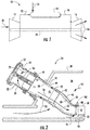
- FIG. 1 illustrates a schematic diagram of an exemplary gas turbine 10.
- the gas turbine 10 generally includes a compressor 12, at least one combustor 14 disposed downstream of the compressor 12 and a turbine 16 disposed downstream of the combustor 14. Additionally, the gas turbine 10 may include one or more shafts 18 that couple the compressor 12 to the turbine 16.
- air 20 flows into the compressor 12 where the air 20 is progressively compressed, thus providing compressed or pressurized air 22 to the combustor 14. At least a portion of the compressed air 22 is mixed with a fuel 24 within the combustor 14 and burned to produce combustion gases 26.
- the combustion gases 26 flow from the combustor 14 into the turbine 16, wherein energy (kinetic and/or thermal) is transferred from the combustion gases 26 to rotor blades (not shown), thus causing shaft 18 to rotate.
- the mechanical rotational energy may then be used for various purposes such as to power the compressor 12 and/or to generate electricity.
- the combustion gases 26 may then be exhausted from the turbine 16.
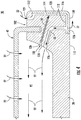
- FIG. 2 is a cross sectional side view of an exemplary combustor 14 as may incorporate various embodiments of the present disclosure.
- the combustor 14 may include an outer casing or compressor discharge casing 28 that at least partially forms a high pressure plenum 30 around various combustion hardware components.
- the high pressure plenum 30 is pressurized with a portion of the compressed air 22 from the compressor 12.
- the combustor 14 may also include an end cover 32 that is coupled to the outer casing 28.
- the end cover 32 and the outer casing 28 may at least partially define a head end volume 34 of the combustor 14.
- the head end volume 34 is in fluid communication with the high pressure plenum 30.
- At least one fuel nozzle 36 extends axially downstream from the end cover 32 and is in fluid communication with the head end volume 34.
- a duct 38 extends downstream from the at least one fuel nozzle 36.
- the duct 38 may at least partially define a hot gas path 40 for routing the combustion gases 26 through the combustor 14 to an inlet 42 of the turbine 16.
- the duct 38 may be formed from a continuous or singular body. In other embodiments, the duct 38 may be formed from multiple ducts coupled together.
- a sleeve 42 such as a flow sleeve and/or an impingement sleeve may surround the duct 38 and form an annular flow passage 44 therebetween.
- the annular flow passage 44 may provide a flow path for routing the compressed air 22 from the high pressure plenum 30 into the head end volume 34.
- an aft frame 100 is connected to or formed as a part of an aft or downstream end 46 of the duct 38.
- the aft frame 100 * may provide structural support for maintaining the shape of the aft end 46 of the duct 38 and/or may provide mounting support for securing the duct 38 to a stationary component such as the outer casing 28, a nozzle mounting ring or the like.
- an axial gap 48 is formed between the aft frame 100 and shroud portions 50 of a first stage stationary nozzle 52 disposed at an inlet to the turbine 16.
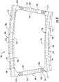
- FIG. 3 provides an upstream view of an exemplary aft frame 100 coupled to an exemplary duct 38 according to various embodiments of the present disclosure.
- the aft frame 100 generally includes a rail or radial projection 102 that extends circumferentially around and radially outwardly from the aft end of the duct 38.
- the rail 102 maybe formed as an inner rail 104 having an arcuate shape, an outer rail 106 radially spaced from the inner rail 102 and also having an arcuate shape complementary to the inner rail 104.
- the rail 102 may further include a first side rail 108 that extends radially between the inner rail 104 and the outer rail 106, and a second side rail 110 circumferentially spaced from the first side rail 108 and that extends radially between the inner rail 104 and the outer rail 106.
- the rail 102 including the inner rail 104, the outer rail 106, the first side rail 108 and the second side rail 110 collectively define an outer surface or face 112 of the aft frame 100 and/or the duct 38.
- a combustion gas recirculation zone may develop proximate to the axial gap 48 ( FIG. 2 ), just downstream from the outer surface 112 of the aft frame 100.
- FIG. 4 provides a cross sectional side view of an exemplary aft frame rail 102 which is intended to be illustrative of one or more of the inner rail 104, the outer rail 106, the first side rail 108 and the second side rail 110 according to at least one embodiment of the present disclosure.
- the rail 102 includes one or more micro-cooling channels 114 and one or more preformed cover plates 116 which cover and in at least one embodiment, at least partially define one or more of the plurality of micro-cooling channels 114.
- FIG. 5 provides a cross sectioned view of a portion of an exemplary rail 102 and a portion of an exemplary preformed cover plate 116 according to at least one embodiment of the present disclosure.
- FIG. 6 provides a cross sectioned view of a portion of an exemplary rail 102 and a portion of an exemplary preformed cover plate 116 according to at least one embodiment of the present disclosure.
- FIG. 7 provides a cross sectioned view of a portion of an exemplary rail 102 and a portion of an exemplary preformed cover plate 116 according to at least one embodiment of the present disclosure.
- the plurality of micro-cooling channels 114 may be defined in or formed along the outer surface 112 and/or the inner surface 114 of the aft frame 100.
- the plurality of micro-cooling channels 114 may be defined in or formed along an inner surface 118 of the preformed cover plate(s) 116.
- FIG. 6 the plurality of micro-cooling channels 114 may be defined in or formed along an inner surface 118 of the preformed cover plate(s) 116.
- a first portion 120 of one or more micro-cooling channels 114 of the plurality of micro-cooling channels 114 may be defined in or formed along the inner surface 118 of the preformed cover plate(s) 116 and a second portion 122 of the one or more micro-cooling channels 114 may be defined in or formed along the outer surface 112 and/or the inner surface 114 of the aft frame 100.
- FIG. 8 provides an enlarged upstream view of an exemplary aft frame 100 according to various embodiments of the present disclosure.
- each micro-cooling channel 114 is in fluid communication with a respective channel inlet 124 and a respective channel outlet 126.
- the channel inlet(s) 124 are in fluid communication with the high pressure plenum 30.
- at least one channel inlet 124 may be defined along a backside surface 128 of the rail 102 and/or the aft frame 100 and may be in fluid communication with the annular flow passage 44.
- one or more channel outlets 126 are disposed and/or are in fluid communication with the annular flow passage 44.
- one or more of the channel outlets 126 may be defined along a respective preformed cover plate 116 of the one or more preformed cover plates 116.
- the outer surface 112 of the aft frame 100 includes at least one but typically a plurality of the micro-cooling channels 114.
- the plurality of micro-cooling channels 114 may be formed in one or more of the inner rail 104, the outer rail 106, the first side rail 108 and/or the second side rail 110.
- the plurality of micro-cooling channels 114 may be the same or different in size or shape from each other.
- one or more micro-cooling channels 114 of the plurality of micro-cooling channels 114 extends in a serpentine pattern.
- one or more micro-cooling channels 114 of the plurality of micro-cooling channels 114 extends in a substantially linear manner.
- the one or more micro-cooling channels 114 of the plurality of micro-cooling channels 114 extends in a serpentine pattern and one or more micro-cooling channels 114 of the plurality of micro-cooling channels 114 extends in a substantially linear manner.
- the plurality of micro-cooling channels 114 may have a width of between about 100 microns ( ⁇ m) and about 3 millimeters (mm) and a depth between about 100 ⁇ m and about 3 mm, as will be discussed below.
- the plurality of micro-cooling channels 114 may have a width and/or depth between about 150 ⁇ m and about 1.5 mm, between about 250 ⁇ m and about 1.25 mm, or between about 300 ⁇ m and about 1 mm.
- the plurality of micro-cooling channels 114 may have a width and/or depth of less than about 50, 100, 150, 200, 250, 300, 350, 400, 450, 500, 600, 700, or 750 ⁇ m.
- the plurality of micro-cooling channels 114 may have circular, semi-circular, oval, curved, rectangular, triangular, or rhomboidal cross-sections. The preceding list is merely illustrative and is not intended to be exhaustive. The width and depth could vary throughout its length. Additionally, in certain embodiments, the plurality of micro-cooling channels 114 may have varying cross-sectional areas. Heat transfer enhancements such as turbulators or dimples may be installed in the plurality of micro-cooling channels 114 as well.
- the preformed cover plate(s) 116 is disposed over a portion of the outer surface 112 and/or the inner surface 114 of the aft frame 100, and more specifically over the plurality of micro-cooling channels 114 to at least partially enclose the plurality of micro-cooling channels 114 therebetween.
- the preformed cover plate 116 is shaped in such a way to form a flush engagement with the outer surface 112 and/or the inner surface 114 of the aft frame 100.
- a flush engagement provides effective sealing and enclosure of the plurality of micro-cooling channels 114.
- the plurality of micro-cooling channels 114 is formed in the preformed cover plate 116 as an alternative to, or in combination with, micro-cooling channels formed in the outer surface 112 and/or the inner surface 114 of the aft frame 100.
- the preformed cover plate 116 may be formed of various suitable materials.
- the preformed cover plate 116 comprises a pre-sintered preform (PSP).
- the preformed cover plate 116 comprises one or more layers of sheet metal. It is further contemplated that the preformed cover plate 116 may be formed of both PSP foil(s) and one or more layers of sheet metal.
- the pre-sintered preform may comprise a mixture of particles comprising a base alloy and a second alloy that have been sintered together at a temperature below their melting points to form an agglomerate and somewhat porous mass.
- Suitable particle size ranges for the powder particles include 150 mesh, or even 325 mesh or smaller to promote rapid sintering of the particles and minimize porosity in the pre-sintered preform to about 10 volume percent or less.
- the density of the pre-sintered preform has a density of 90% or better. In even some embodiments, the pre-sintered preform has a density of 95% or better.
- the pre-sintered perform can be subjected to hot isostatic pressing (HIP) or vacuum/inert atmosphere pressing to promote higher densities.
- HIP hot isostatic pressing
- the base alloy of the pre-sintered preform can comprise any composition such as one similar to the aft frame 100 to promote common physical properties between the pre-sintered preform and the aft frame 100.
- the base alloy and the aft frame 100 share a common composition (i.e., they are the same type of material).
- the base alloy can comprise nickel-based superalloys such as Rene N4, Rene N5, Rene 108, GTD-111®, GTD-222®, GTD-444®, IN-738 and MarM 247 or cobalt-based superalloys such as FSX-414 as discussed above.
- the properties for the base alloy include chemical and metallurgical compatibility with the base article, such as high fatigue strength, low tendency for cracking, oxidation resistance and/or machinability.
- the base alloy may comprise a melting point of within about 25° C. of the melting temperature of the aft frame 100.
- the base alloy may comprise a compositional range of, by weight, about 2.5 to 11% cobalt, 7 to 9% chromium, 3.5 to 11% tungsten, 4.5 to 8% aluminum, 2.5 to 6% tantalum, 0.02 to 1.2% titanium, 0.1 to 1.8% hafnium, 0.1 to 0.8% molybdenum, 0.01 to 0.17% carbon, up to 0.08% zirconium, up to 0.60 silicon, up to 2.0 rhenium, the balance nickel and incidental impurities.
- the base alloy may comprise a compositional range of, by weight, about 9 to 11% cobalt, 8 to 8.8% chromium, 9.5 to 10.5% tungsten, 5.3 to 5.7% aluminum, 2.8 to 2.3% tantalum, 0.9 to 1.2% titanium, 1.2 to 1.6% hafnium, 0.5 to 0.8% molybdenum, 0.13 to 0.17% carbon, 0.03 to 0.08% zirconium, the balance nickel and incidental impurities.
- these listed materials and compositions are exemplary only and non-limiting and other alloys may alternatively or additionally be used.
- the particular composition of the base alloy for the pre-sintered preform may depend on the composition of the aft frame 100.
- the pre-sintered preform further comprises a second alloy.
- the second alloy may also have a composition similar to the aft frame 100 but further contain a melting point depressant to promote sintering of the base alloy and the second alloy particles and enable bonding of the pre-sintered preform to the aft frame 100 at temperatures below the melting point of the aft frame 100.
- the melting point depressant can comprise boron and/or silicon.
- the second alloy may comprise a melting point of about 25° C. to about 50° C. below the grain growth or incipient melting temperature of the aft frame 100. Such embodiments may better preserve the desired microstructure of the aft frame 100 during the heating process.
- the second alloy may comprise a compositional range of, by weight, about 9 to 10% cobalt, 11 to 16% chromium, 3 to 4% aluminum, 2.25 to 2.75% tantalum, 1.5 to 3.0% boron, up to 5% silicon, up to 1.0% yttrium, the balance nickel and incidental impurities.
- the second alloy may comprise commercially available Amdry DF4B nickel brazing alloy.
- composition of the second alloy of the pre-sintered preform may depend on the composition of the aft frame 100.
- the pre-sintered preform can comprise any relative amounts of the base alloy and the second alloy that are sufficient to provide enough melting point depressant to ensure wetting and bonding (e.g., diffusion/brazing bonding) of the particles of the base alloy and the second alloy to each other and to the outer surface 26 of the aft frame 100.
- the second alloy can comprise at least about 10 weight percent of the pre-sintered preform.
- the second alloy can comprise no more than 70 weight percent of the pre-sintered preform. Such embodiments may provide a sufficient amount of melting point depressant while limiting potential reduction of the mechanical and environmental properties of the subsequent heating.
- the base alloy can comprise the remainder of the pre-sintered preform (e.g., between about 30 weight percent and about 70 weight percent of the pre-sintered preform).
- the particles of the base alloy can comprise about 40 weight percent to about 70 weight percent of the pre-sintered preform with the balance of the composition comprising particles of the second alloy.
- a binder may be initially blended with the particles of the base alloy and the second alloy to form a cohesive mass that can be more readily shaped prior to sintering.
- the binder can include, for example, a binder commercially available under the name NICROBRAZ-S from the Wall Colmonoy Corporation.
- Other potentially suitable binders include NICROBRAZ 320, VITTA GEL from Vitta Corporation, and others including adhesives commercially available from Cotronics Corporation, all of which may volatilize cleanly during sintering.
- the pre-sintered preform may actually comprise a plurality of layers, each being attached to each other before or after being connected to the aft frame 100.
- the plurality of layers may combine to form one or more micro-cooling channels 114 of the plurality of micro-cooling channels 114 or a single layer may comprise one or more micro-cooling channels 114 of the plurality of micro-cooling channels 114 while additional layers are present for additional protection of the aft frame 100.
- Such embodiments may also allow for specific thermal properties in different zones of the pre-sintered preform to be individually tailored.
- the pre-sintered preform may be combined with one or more metal layers or sections.
- the pre-sintered preform may form the sides of the one or more micro-cooling channels 114 of the plurality of micro-cooling channels 114 while a thin metal film closes off the top of the respective micro-cooling channel 114.
- the metal film may be bonded prior to, after or while the pre-sintered preform is bonded to the aft frame 100.
- the pre-sintered preform may bond with the aft frame 100 via one or more additional metal layers.
- a cooling medium such as the compressed air 22 from the compressor 12, enters at least one channel inlet 124 of the one or more channel inlets 124 and flows through the plurality of micro-cooling channels 114 defined beneath the preformed cover plate 116 and/or through the plurality of micro-cooling channels 114 defined along the inner surface 118 of the preformed cover plate 116, thereby transferring thermal energy provided by the combustion gases 26 away from the aft frame 100 and/or the preformed cover plate 116.
- a portion or all of the cooling medium may be exhausted from the micro-cooling channels 114 into the annular flow passage 44 via one or more of the channel outlets 126 disposed within the annular flow passage 44 so that it may be mixed with the compressed air 22 flowing though the annular flow passage 4 upstream from the fuel nozzle 36, thereby increasing the compressed air flow to the head end volume 34 of the combustor 14.
- a portion or all of the cooling medium may be exhausted from the micro-cooling channels 114 via one or more of the channel outlets 126 defined along the preformed cover plate 116, thereby providing a film of cooling medium to an outer surface 130 ( FIG. 4 ) of the preformed cover plate 116.
Landscapes
- Engineering & Computer Science (AREA)
- Mechanical Engineering (AREA)
- General Engineering & Computer Science (AREA)
- Chemical & Material Sciences (AREA)
- Combustion & Propulsion (AREA)
- Turbine Rotor Nozzle Sealing (AREA)
- Gas Burners (AREA)
Abstract
Description
- The present invention generally involves an igniter for a combustor. More specifically, the invention relates to a combustor having an aft frame where the aft frame includes micro-channels for cooling.
- During operation of a gas turbine engine, pressurized air from a compressor flows into a head end volume defined within the combustor. The pressurized air flows from the head end volume into an inlet to a corresponding premix passage of a respective fuel nozzle. Fuel is injected into the flow of pressurized air within the premix passage where it mixes with the pressurized air so as to provide a fuel and air mixture to a combustion zone or chamber defined downstream from the fuel nozzle. The fuel and air mixture is burned in the combustion chamber to produce high temperature and high velocity combustion gases.
- The combustion gases travel from the combustion chamber to an inlet of a turbine portion of the gas turbine engine via a liner or duct that extends at least partially between the combustion chamber and the turbine inlet. An aft frame is typically mounted to or formed at a downstream end of the duct. The aft frame may be used to reinforce the shape of the aft end of the duct and/or for mounting the duct to a support structure such as a compressor discharge casing. As such, the igniter housing may be subject to an operational temperature that may cause the igniter lead to deteriorate over time. Therefore, improved cooling of the igniter housing may improve performance of the igniter.
- Aspects and advantages are set forth below in the following description, or may be obvious from the description, or may be learned through practice.
- One embodiment of the present disclosure is directed to an aft frame for a combustor. The aft frame includes a rail that extends circumferentially around the aft frame. The rail defines an outer surface of the aft frame. A preformed cover plate having an inner surface is attached to the outer surface of the aft frame. A plurality of micro-cooling channels is formed within at least one of the inner surface of the preformed cover plate and the outer surface of the aft frame. The preformed cover plate extends across the plurality of micro-cooling channels.
- Another embodiment of the present disclosure is a combustor. The combustor includes a duct having an aft end, an annular flow passage surrounding the duct and an aft frame. The aft frame is disposed at the aft end of the duct and includes a rail that extends circumferentially around the aft end of the duct. The rail defines an outer surface of the aft frame. A preformed cover plate includes an inner surface that is attached to the outer surface of the aft frame. A plurality of micro-cooling channels is formed within at least one of the inner surface of the preformed cover plate and the outer surface of the aft frame. The preformed cover plate extends across the plurality of micro-cooling channels.
- Those of ordinary skill in the art will better appreciate the features and aspects of such embodiments, and others, upon review of the specification.
- A full and enabling disclosure of the of various embodiments, including the best mode thereof to one skilled in the art, is set forth more particularly in the remainder of the specification, including reference to the accompanying figures, in which:
-
FIG. 1 is a functional block diagram of an exemplary gas turbine that may incorporate various embodiments of the present disclosure; -
FIG. 2 is a cross sectional side view of anexemplary combustor 14 as may incorporate various embodiments of the present disclosure; -
FIG. 3 is an upstream view of an exemplary aft frame coupled to an exemplary duct according to various embodiments of the present disclosure; -
FIG. 4 is a cross sectional side view of an exemplary aft frame rail which is intended to be illustrative of one or more of an inner rail, an outer rail, a first side rail and/or a second side rail of the aft frame rail according to at least one embodiment of the present disclosure; -
FIG. 5 is a cross sectioned view of a portion of an exemplary aft frame rail and a portion of an exemplary preformed cover plate according to at least one embodiment of the present disclosure; -
FIG. 6 is a cross sectioned view of a portion of an exemplary aft frame rail and a portion of an exemplary preformed cover plate according to at least one embodiment of the present disclosure; -
FIG. 7 is a cross sectioned view of a portion of an exemplary aft frame rail and a portion of an exemplary preformed cover plate according to at least one embodiment of the present disclosure; and -
FIG. 8 is an enlarged upstream view of an exemplary aft frame according to various embodiments of the present disclosure. - Reference will now be made in detail to present embodiments of the disclosure, one or more examples of which are illustrated in the accompanying drawings. The detailed description uses numerical and letter designations to refer to features in the drawings. Like or similar designations in the drawings and description have been used to refer to like or similar parts of the disclosure.
- As used herein, the terms "first," "second," and "third" may be used interchangeably to distinguish one component from another and are not intended to signify location or importance of the individual components. The terms "upstream" and "downstream" refer to the relative direction with respect to fluid flow in a fluid pathway. For example, "upstream" refers to the direction from which the fluid flows, and "downstream" refers to the direction to which the fluid flows. The term "radially" refers to the relative direction that is substantially perpendicular to an axial centerline of a particular component, the term "axially" refers to the relative direction that is substantially parallel and/or coaxially aligned to an axial centerline of a particular component, and the term "circumferentially" refers to the relative direction that extends around the axial centerline of a particular component.
- The terminology used herein is for the purpose of describing particular embodiments only and is not intended to be limiting. As used herein, the singular forms "a", "an" and "the" are intended to include the plural forms as well, unless the context clearly indicates otherwise. It will be further understood that the terms "comprises" and/or "comprising," when used in this specification, specify the presence of stated features, integers, steps, operations, elements, and/or components, but do not preclude the presence or addition of one or more other features, integers, steps, operations, elements, components, and/or groups thereof.
- Each example is provided by way of explanation, not limitation. In fact, it will be apparent to those skilled in the art that modifications and variations can be made without departing from the scope or spirit thereof. For instance, features illustrated or described as part of one embodiment may be used on another embodiment to yield a still further embodiment. Thus, it is intended that the present disclosure covers such modifications and variations as come within the scope of the appended claims and their equivalents. Although exemplary embodiments of the present disclosure will be described generally in the context of an aft frame for a combustor of a land based power generating gas turbine for purposes of illustration, one of ordinary skill in the art will readily appreciate that embodiments of the present disclosure may be applied to any style or type of combustor for a turbomachine and are not limited to combustors or combustion systems for land based power generating gas turbines unless specifically recited in the claims.
- Referring now to the drawings,
FIG. 1 illustrates a schematic diagram of anexemplary gas turbine 10. Thegas turbine 10 generally includes acompressor 12, at least onecombustor 14 disposed downstream of thecompressor 12 and aturbine 16 disposed downstream of thecombustor 14. Additionally, thegas turbine 10 may include one ormore shafts 18 that couple thecompressor 12 to theturbine 16. - During operation,
air 20 flows into thecompressor 12 where theair 20 is progressively compressed, thus providing compressed or pressurizedair 22 to thecombustor 14. At least a portion of the compressedair 22 is mixed with afuel 24 within thecombustor 14 and burned to producecombustion gases 26. Thecombustion gases 26 flow from thecombustor 14 into theturbine 16, wherein energy (kinetic and/or thermal) is transferred from thecombustion gases 26 to rotor blades (not shown), thus causingshaft 18 to rotate. The mechanical rotational energy may then be used for various purposes such as to power thecompressor 12 and/or to generate electricity. Thecombustion gases 26 may then be exhausted from theturbine 16. -
FIG. 2 is a cross sectional side view of anexemplary combustor 14 as may incorporate various embodiments of the present disclosure. As shown inFIG, 2 , thecombustor 14 may include an outer casing orcompressor discharge casing 28 that at least partially forms ahigh pressure plenum 30 around various combustion hardware components. Thehigh pressure plenum 30 is pressurized with a portion of thecompressed air 22 from thecompressor 12. Thecombustor 14 may also include anend cover 32 that is coupled to theouter casing 28. Theend cover 32 and theouter casing 28 may at least partially define ahead end volume 34 of thecombustor 14. Thehead end volume 34 is in fluid communication with thehigh pressure plenum 30. At least onefuel nozzle 36 extends axially downstream from theend cover 32 and is in fluid communication with thehead end volume 34. - A
duct 38 extends downstream from the at least onefuel nozzle 36. Theduct 38 may at least partially define ahot gas path 40 for routing thecombustion gases 26 through thecombustor 14 to aninlet 42 of theturbine 16. In particular embodiments, theduct 38 may be formed from a continuous or singular body. In other embodiments, theduct 38 may be formed from multiple ducts coupled together. Asleeve 42 such as a flow sleeve and/or an impingement sleeve may surround theduct 38 and form anannular flow passage 44 therebetween. Theannular flow passage 44 may provide a flow path for routing thecompressed air 22 from thehigh pressure plenum 30 into thehead end volume 34. In various embodiments, anaft frame 100 is connected to or formed as a part of an aft ordownstream end 46 of theduct 38. Theaft frame 100 * may provide structural support for maintaining the shape of theaft end 46 of theduct 38 and/or may provide mounting support for securing theduct 38 to a stationary component such as theouter casing 28, a nozzle mounting ring or the like. When installed in thecombustor 14, anaxial gap 48 is formed between theaft frame 100 andshroud portions 50 of a first stagestationary nozzle 52 disposed at an inlet to theturbine 16. -
FIG. 3 provides an upstream view of an exemplaryaft frame 100 coupled to anexemplary duct 38 according to various embodiments of the present disclosure. As shown inFIG. 3 , theaft frame 100 generally includes a rail orradial projection 102 that extends circumferentially around and radially outwardly from the aft end of theduct 38. Therail 102 maybe formed as aninner rail 104 having an arcuate shape, anouter rail 106 radially spaced from theinner rail 102 and also having an arcuate shape complementary to theinner rail 104. Therail 102 may further include afirst side rail 108 that extends radially between theinner rail 104 and theouter rail 106, and asecond side rail 110 circumferentially spaced from thefirst side rail 108 and that extends radially between theinner rail 104 and theouter rail 106. Therail 102 including theinner rail 104, theouter rail 106, thefirst side rail 108 and thesecond side rail 110 collectively define an outer surface or face 112 of theaft frame 100 and/or theduct 38. During operation of thecombustor 14, a combustion gas recirculation zone may develop proximate to the axial gap 48 (FIG. 2 ), just downstream from theouter surface 112 of theaft frame 100. As a result, theaft frame 100 may be exposed to undesirable thermal stresses and thus, must be effectively cooled.FIG. 4 provides a cross sectional side view of an exemplaryaft frame rail 102 which is intended to be illustrative of one or more of theinner rail 104, theouter rail 106, thefirst side rail 108 and thesecond side rail 110 according to at least one embodiment of the present disclosure. In various embodiments, as shown inFIG. 4 , therail 102 includes one or moremicro-cooling channels 114 and one or morepreformed cover plates 116 which cover and in at least one embodiment, at least partially define one or more of the plurality ofmicro-cooling channels 114. -
FIG. 5 provides a cross sectioned view of a portion of anexemplary rail 102 and a portion of an exemplarypreformed cover plate 116 according to at least one embodiment of the present disclosure.FIG. 6 provides a cross sectioned view of a portion of anexemplary rail 102 and a portion of an exemplarypreformed cover plate 116 according to at least one embodiment of the present disclosure.FIG. 7 provides a cross sectioned view of a portion of anexemplary rail 102 and a portion of an exemplarypreformed cover plate 116 according to at least one embodiment of the present disclosure. - In particular embodiments, as illustrated in
FIGS. 4 and5 collectively, the plurality ofmicro-cooling channels 114 may be defined in or formed along theouter surface 112 and/or theinner surface 114 of theaft frame 100. In particular embodiments, as shown inFIG. 6 , the plurality ofmicro-cooling channels 114 may be defined in or formed along aninner surface 118 of the preformed cover plate(s) 116. In particular embodiments, as shown inFIG. 7 , afirst portion 120 of one or moremicro-cooling channels 114 of the plurality ofmicro-cooling channels 114 may be defined in or formed along theinner surface 118 of the preformed cover plate(s) 116 and asecond portion 122 of the one or moremicro-cooling channels 114 may be defined in or formed along theouter surface 112 and/or theinner surface 114 of theaft frame 100. -
FIG. 8 provides an enlarged upstream view of an exemplaryaft frame 100 according to various embodiments of the present disclosure. In various embodiments, as shown inFIGS. 4 and8 collectively, eachmicro-cooling channel 114 is in fluid communication with arespective channel inlet 124 and arespective channel outlet 126. In particular embodiments, the channel inlet(s) 124 are in fluid communication with thehigh pressure plenum 30. In particular embodiments, at least onechannel inlet 124 may be defined along abackside surface 128 of therail 102 and/or theaft frame 100 and may be in fluid communication with theannular flow passage 44. In particular embodiments, one ormore channel outlets 126 are disposed and/or are in fluid communication with theannular flow passage 44. In particular embodiments, one or more of thechannel outlets 126 may be defined along a respectivepreformed cover plate 116 of the one or morepreformed cover plates 116. - In various embodiments, as illustrated in
FIG. 8 , theouter surface 112 of theaft frame 100 includes at least one but typically a plurality of themicro-cooling channels 114. - The plurality of
micro-cooling channels 114 may be formed in one or more of theinner rail 104, theouter rail 106, thefirst side rail 108 and/or thesecond side rail 110. The plurality ofmicro-cooling channels 114 may be the same or different in size or shape from each other. For example, in particular embodiments, one or moremicro-cooling channels 114 of the plurality ofmicro-cooling channels 114 extends in a serpentine pattern. In particular embodiments, one or moremicro-cooling channels 114 of the plurality ofmicro-cooling channels 114 extends in a substantially linear manner. In particular embodiments, the one or moremicro-cooling channels 114 of the plurality ofmicro-cooling channels 114 extends in a serpentine pattern and one or moremicro-cooling channels 114 of the plurality ofmicro-cooling channels 114 extends in a substantially linear manner. - In accordance with certain embodiments, the plurality of
micro-cooling channels 114 may have a width of between about 100 microns (µm) and about 3 millimeters (mm) and a depth between about 100 µm and about 3 mm, as will be discussed below. For example, the plurality ofmicro-cooling channels 114 may have a width and/or depth between about 150 µm and about 1.5 mm, between about 250 µm and about 1.25 mm, or between about 300 µm and about 1 mm. - In certain embodiments, the plurality of
micro-cooling channels 114 may have a width and/or depth of less than about 50, 100, 150, 200, 250, 300, 350, 400, 450, 500, 600, 700, or 750 µm. The plurality ofmicro-cooling channels 114 may have circular, semi-circular, oval, curved, rectangular, triangular, or rhomboidal cross-sections. The preceding list is merely illustrative and is not intended to be exhaustive. The width and depth could vary throughout its length. Additionally, in certain embodiments, the plurality ofmicro-cooling channels 114 may have varying cross-sectional areas. Heat transfer enhancements such as turbulators or dimples may be installed in the plurality ofmicro-cooling channels 114 as well. - In particular embodiments, as shown in
FIGS. 4 through 7 collectively, the preformed cover plate(s) 116 is disposed over a portion of theouter surface 112 and/or theinner surface 114 of theaft frame 100, and more specifically over the plurality ofmicro-cooling channels 114 to at least partially enclose the plurality ofmicro-cooling channels 114 therebetween. The preformedcover plate 116 is shaped in such a way to form a flush engagement with theouter surface 112 and/or theinner surface 114 of theaft frame 100. A flush engagement provides effective sealing and enclosure of the plurality ofmicro-cooling channels 114. It is contemplated that the plurality ofmicro-cooling channels 114 is formed in the preformedcover plate 116 as an alternative to, or in combination with, micro-cooling channels formed in theouter surface 112 and/or theinner surface 114 of theaft frame 100. - The preformed
cover plate 116 may be formed of various suitable materials. In one embodiment, the preformedcover plate 116 comprises a pre-sintered preform (PSP). In another embodiment, the preformedcover plate 116 comprises one or more layers of sheet metal. It is further contemplated that the preformedcover plate 116 may be formed of both PSP foil(s) and one or more layers of sheet metal. - The pre-sintered preform may comprise a mixture of particles comprising a base alloy and a second alloy that have been sintered together at a temperature below their melting points to form an agglomerate and somewhat porous mass. Suitable particle size ranges for the powder particles include 150 mesh, or even 325 mesh or smaller to promote rapid sintering of the particles and minimize porosity in the pre-sintered preform to about 10 volume percent or less. In some embodiments, the density of the pre-sintered preform has a density of 90% or better. In even some embodiments, the pre-sintered preform has a density of 95% or better. As discussed below, the pre-sintered perform can be subjected to hot isostatic pressing (HIP) or vacuum/inert atmosphere pressing to promote higher densities.
- The base alloy of the pre-sintered preform can comprise any composition such as one similar to the
aft frame 100 to promote common physical properties between the pre-sintered preform and theaft frame 100. For example, in some embodiments, the base alloy and theaft frame 100 share a common composition (i.e., they are the same type of material). In some embodiments, the base alloy can comprise nickel-based superalloys such as Rene N4, Rene N5,Rene 108, GTD-111®, GTD-222®, GTD-444®, IN-738 and MarM 247 or cobalt-based superalloys such as FSX-414 as discussed above. In some embodiments, the properties for the base alloy include chemical and metallurgical compatibility with the base article, such as high fatigue strength, low tendency for cracking, oxidation resistance and/or machinability. - In some embodiments, the base alloy may comprise a melting point of within about 25° C. of the melting temperature of the
aft frame 100. In some embodiments, the base alloy may comprise a compositional range of, by weight, about 2.5 to 11% cobalt, 7 to 9% chromium, 3.5 to 11% tungsten, 4.5 to 8% aluminum, 2.5 to 6% tantalum, 0.02 to 1.2% titanium, 0.1 to 1.8% hafnium, 0.1 to 0.8% molybdenum, 0.01 to 0.17% carbon, up to 0.08% zirconium, up to 0.60 silicon, up to 2.0 rhenium, the balance nickel and incidental impurities. In even some embodiments, the base alloy may comprise a compositional range of, by weight, about 9 to 11% cobalt, 8 to 8.8% chromium, 9.5 to 10.5% tungsten, 5.3 to 5.7% aluminum, 2.8 to 2.3% tantalum, 0.9 to 1.2% titanium, 1.2 to 1.6% hafnium, 0.5 to 0.8% molybdenum, 0.13 to 0.17% carbon, 0.03 to 0.08% zirconium, the balance nickel and incidental impurities. It should be appreciated that while specific materials and compositions have been listed herein for the composition of the base alloy of the pre-sintered preform, these listed materials and compositions are exemplary only and non-limiting and other alloys may alternatively or additionally be used. Furthermore, it should be appreciated that the particular composition of the base alloy for the pre-sintered preform may depend on the composition of theaft frame 100. - As discussed above, the pre-sintered preform further comprises a second alloy. The second alloy may also have a composition similar to the
aft frame 100 but further contain a melting point depressant to promote sintering of the base alloy and the second alloy particles and enable bonding of the pre-sintered preform to theaft frame 100 at temperatures below the melting point of theaft frame 100. For example, in some embodiments the melting point depressant can comprise boron and/or silicon. - In some embodiments, the second alloy may comprise a melting point of about 25° C. to about 50° C. below the grain growth or incipient melting temperature of the
aft frame 100. Such embodiments may better preserve the desired microstructure of theaft frame 100 during the heating process. In some embodiments, the second alloy may comprise a compositional range of, by weight, about 9 to 10% cobalt, 11 to 16% chromium, 3 to 4% aluminum, 2.25 to 2.75% tantalum, 1.5 to 3.0% boron, up to 5% silicon, up to 1.0% yttrium, the balance nickel and incidental impurities. For example, in some embodiments the second alloy may comprise commercially available Amdry DF4B nickel brazing alloy. It should also be appreciated that while specific materials and compositions have been listed herein for the composition of the second alloy of the pre-sintered preform, these listed materials and compositions are exemplary only and non-limiting and other alloys may alternatively or additionally be used. Furthermore, it should be appreciated that the particular composition of the second alloy for the pre-sintered preform may depend on the composition of theaft frame 100. - The pre-sintered preform can comprise any relative amounts of the base alloy and the second alloy that are sufficient to provide enough melting point depressant to ensure wetting and bonding (e.g., diffusion/brazing bonding) of the particles of the base alloy and the second alloy to each other and to the
outer surface 26 of theaft frame 100. For example, in some embodiments the second alloy can comprise at least about 10 weight percent of the pre-sintered preform. In some embodiments the second alloy can comprise no more than 70 weight percent of the pre-sintered preform. Such embodiments may provide a sufficient amount of melting point depressant while limiting potential reduction of the mechanical and environmental properties of the subsequent heating. Furthermore, in these embodiments, the base alloy can comprise the remainder of the pre-sintered preform (e.g., between about 30 weight percent and about 70 weight percent of the pre-sintered preform). In even some embodiments, the particles of the base alloy can comprise about 40 weight percent to about 70 weight percent of the pre-sintered preform with the balance of the composition comprising particles of the second alloy. It should be appreciated that while specific relative ranges of the base alloy and the second alloy have been presented herein, these ranges are exemplary only and non-limiting and any other relative compositions may also be realized such that a sufficient amount of melting point depressant is provided as discussed above. - Aside from the particles of the base alloy and the second alloy, no other constituents may be required within the pre-sintered preform. However, in some embodiments, a binder may be initially blended with the particles of the base alloy and the second alloy to form a cohesive mass that can be more readily shaped prior to sintering. In such embodiments, the binder can include, for example, a binder commercially available under the name NICROBRAZ-S from the Wall Colmonoy Corporation. Other potentially suitable binders include NICROBRAZ 320, VITTA GEL from Vitta Corporation, and others including adhesives commercially available from Cotronics Corporation, all of which may volatilize cleanly during sintering.
- In some embodiments, the pre-sintered preform may actually comprise a plurality of layers, each being attached to each other before or after being connected to the
aft frame 100. In such embodiments, the plurality of layers may combine to form one or moremicro-cooling channels 114 of the plurality ofmicro-cooling channels 114 or a single layer may comprise one or moremicro-cooling channels 114 of the plurality ofmicro-cooling channels 114 while additional layers are present for additional protection of theaft frame 100. Such embodiments may also allow for specific thermal properties in different zones of the pre-sintered preform to be individually tailored. In even some embodiments, the pre-sintered preform may be combined with one or more metal layers or sections. For example, the pre-sintered preform may form the sides of the one or moremicro-cooling channels 114 of the plurality ofmicro-cooling channels 114 while a thin metal film closes off the top of the respectivemicro-cooling channel 114. In such embodiments, the metal film may be bonded prior to, after or while the pre-sintered preform is bonded to theaft frame 100. Or, in some embodiments, the pre-sintered preform may bond with theaft frame 100 via one or more additional metal layers. - In operation, a cooling medium such as the
compressed air 22 from thecompressor 12, enters at least onechannel inlet 124 of the one ormore channel inlets 124 and flows through the plurality ofmicro-cooling channels 114 defined beneath the preformedcover plate 116 and/or through the plurality ofmicro-cooling channels 114 defined along theinner surface 118 of the preformedcover plate 116, thereby transferring thermal energy provided by thecombustion gases 26 away from theaft frame 100 and/or the preformedcover plate 116. In particular embodiments, a portion or all of the cooling medium may be exhausted from themicro-cooling channels 114 into theannular flow passage 44 via one or more of thechannel outlets 126 disposed within theannular flow passage 44 so that it may be mixed with thecompressed air 22 flowing though the annular flow passage 4 upstream from thefuel nozzle 36, thereby increasing the compressed air flow to thehead end volume 34 of thecombustor 14. In particular embodiments, a portion or all of the cooling medium may be exhausted from themicro-cooling channels 114 via one or more of thechannel outlets 126 defined along the preformedcover plate 116, thereby providing a film of cooling medium to an outer surface 130 (FIG. 4 ) of the preformedcover plate 116. - This written description uses examples to disclose the invention, and also to enable any person skilled in the art to practice the invention, including making and using any devices or systems and performing any incorporated methods. The patentable scope of the invention is defined by the claims, and may include other examples that occur to those skilled in the art. Such other examples are intended to be within the scope of the claims if they include structural elements that do not differ from the literal language of the claims, or if they include equivalent structural elements with insubstantial differences from the literal language of the claims.
- Various aspects and embodiments of the present invention are defined by the following numbered clauses:
- 1. An aft frame for a combustor, comprising:
- a rail extending circumferentially around the aft frame, the rail defining an outer surface of the aft frame; and
- a preformed cover plate having an inner surface attached to the outer surface of the aft frame;
- wherein a plurality of micro-cooling channels is formed within at least one of the inner surface of the preformed cover plate and the outer surface of the aft frame, wherein the preformed cover plate extends across the plurality of micro-cooling channels.
- 2. The aft frame as in clause 1, wherein the plurality of micro-cooling channels is formed in the outer surface of the aft frame beneath the preformed cover plate.
- 3. The aft frame as in clause 1 or 2, wherein the plurality of micro-cooling channels is formed in the inner surface of the preformed cover plate.
- 4. The aft frame as in any preceding clause, wherein a portion of at least one micro-cooling channel of the plurality of micro-cooling channels is partially formed in the outer surface of the aft frame and is partially formed in the inner surface of the preformed cover plate.
- 5. The aft frame as in any preceding clause, wherein the preformed cover plate comprises a pre-sintered preform.
- 6. The aft frame as in any preceding clause, wherein the preformed cover plate comprises one or more layers of sheet metal.
- 7. The aft frame as in any preceding clause, wherein the preformed cover plate comprises a pre-sintered preform and one or more layers of sheet metal.
- 8. The aft frame as in any preceding clause, wherein the preformed cover plate is flush with the outer surface of the aft frame.
- 9. The aft frame as in any preceding clause, wherein one or more micro-cooling channels of the plurality of micro-cooling channels is formed in serpentine pattern.
- 10. The aft frame as in any preceding clause, wherein the plurality of micro-cooling channels is in fluid communication with at least one channel inlet and at least one channel outlet.
- 11. The aft frame as in any preceding clause, wherein the at least one channel inlet is defined along a backside surface of the aft frame.
- 12. The aft frame as in any preceding clause, wherein the at least one channel inlet is defined along the outer surface of the aft frame.
- 13. The aft frame as in any preceding clause, wherein the at least one channel outlet is defined along a backside surface of the aft frame.
- 14. The aft frame as in any preceding clause, wherein the at least one channel outlet is defined along the preformed cover plate.
- 15. The aft frame as in any preceding clause, wherein the rail includes an inner rail, an outer rail, a first side rail and a second side rail.
- 16. The aft frame as in any preceding clause, wherein one or more micro-cooling channels of the plurality of micro-cooling channels is disposed along the inner rail.
- 17. The aft frame as in any preceding clause, wherein one or more micro-cooling channels of the plurality of micro-cooling channels is disposed along the outer rail.
- 18. The aft frame as in any preceding clause, wherein one or more micro-cooling channels of the plurality of micro-cooling channels is disposed along the first side rail.
- 19. The aft frame as in any preceding clause, wherein one or more micro-cooling channels of the plurality of micro-cooling channels is disposed along the second side rail.
- 20. A combustor, comprising:
- a duct having an aft end;
- an annular flow passage surrounding the duct;
- an aft frame an aft frame disposed at the aft end of the duct, wherein the aft frame includes a rail extending circumferentially around the aft end of the duct, the rail defining an outer surface of the aft frame; and
- a preformed cover plate having an inner surface attached to the outer surface of the aft frame;
- wherein a plurality of micro-cooling channels is formed within at least one of the inner surface of the preformed cover plate and the outer surface of the aft frame, wherein the preformed cover plate extends across the plurality of micro-cooling channels.
- 21. The combustor as in any preceding clause, wherein the plurality of micro-cooling channels is formed in the outer surface of the aft frame beneath the preformed cover plate.
- 22. The combustor as in any preceding clause, wherein the plurality of micro-cooling channels is formed in the inner surface of the preformed cover plate adjacent to the outer surface of the aft frame.
- 23. The combustor as in any preceding clause, wherein a first portion of at least one micro-cooling channel of the plurality of micro-cooling channels is formed in the outer surface of the aft frame and a second portion of the same micro-cooling channel is formed in the inner surface of the preformed cover plate.
- 24. The combustor as in any preceding clause, wherein the preformed cover plate comprises a pre-sintered preform.
- 25. The combustor as in any preceding clause, wherein the preformed cover plate comprises one or more layers of sheet metal.
- 26. The combustor as in any preceding clause, wherein the preformed cover plate comprises a pre-sintered preform and one or more layers of sheet metal.
- 27. The combustor as in any preceding clause, wherein the preformed cover plate is flush with the outer surface of the aft frame.
- 28. The combustor as in any preceding clause, wherein one or more micro-cooling channels of the plurality of micro-cooling channels is formed in serpentine pattern.
- 29. The combustor as in any preceding clause, wherein the plurality of micro-cooling channels is in fluid communication with at least one channel inlet and at least one channel outlet.
- 30. The combustor as in any preceding clause, wherein the at least one channel inlet is defined along a backside surface of the aft frame.
- 31. The combustor as in any preceding clause, wherein the at least one channel inlet is defined in the backside surface of the aft frame and is in fluid communication with the annular flow passage.
- 32. The combustor as in any preceding clause, wherein the at least one channel outlet is defined along the backside surface of the aft frame and is in fluid communication with the annular flow passage.
- 33. The combustor as in any preceding clause, wherein the at least one channel outlet is defined in the outer surface of the aft frame.
- 34. The combustor as in any preceding clause, wherein the rail includes an inner rail, an outer rail, a first side rail and a second side rail.
- 35. The combustor as in any preceding clause, wherein one or more micro-cooling channels of the plurality of micro-cooling channels is disposed along the inner rail.
- 36. The combustor as in any preceding clause, wherein one or more micro-cooling channels of the plurality of micro-cooling channels is disposed along the outer rail.
- 37. The combustor as in any preceding clause, wherein one or more micro-cooling channels of the plurality of micro-cooling channels is disposed along the first side rail.
- 38. The combustor as in any preceding clause, wherein one or more micro-cooling channels of the plurality of micro-cooling channels is disposed along the second side rail.
Claims (15)
- An aft frame (100) for a combustor (14), comprising:a rail (102) extending circumferentially around the aft frame (100), the rail (102) defining an outer surface (112) of the aft frame (100); anda preformed cover plate (116) having an inner surface (118) attached to the outer surface (112) of the aft frame (100);wherein a plurality of micro-cooling channels (114) is formed within at least one of the inner surface (118) of the preformed cover plate (116) and the outer surface (112) of the aft frame (100), wherein the preformed cover plate (116) extends across the plurality of micro-cooling channels (114).
- The aft frame (100) as in claim 1, wherein the plurality of micro-cooling channels (114) is formed in the outer surface (112) of the aft frame (100) beneath the preformed cover plate (116).
- The aft frame (100) as in claim 1, wherein the plurality of micro-cooling channels (114) is formed in the inner surface (118) of the preformed cover plate (116).
- The aft frame (100) as in claim 1, wherein a portion of at least one micro-cooling channel (114) of the plurality of micro-cooling channels (114) is partially formed in the outer surface (112) of the aft frame (100) and is partially formed in the inner surface (118) of the preformed cover plate (116).
- The aft frame (100) as in any preceding claim, wherein the preformed cover plate (116) comprises a pre-sintered preform.
- The aft frame (100) as in any of claims 1 to 5, wherein the preformed cover plate (116) comprises one or more layers of sheet metal.
- The aft frame (100) as in any of claims 1 to 5, wherein the preformed cover plate (116) comprises a pre-sintered preform and one or more layers of sheet metal.
- The aft frame (100) as in any preceding claim, wherein the preformed cover plate (116) is flush with the outer surface (112) of the aft frame (100).
- The aft frame (100) as in any preceding claim, wherein one or more micro-cooling channels (114) of the plurality of micro-cooling channels (114) is formed in serpentine pattern.
- The aft frame (100) as in any preceding claim, wherein the plurality of micro-cooling channels (114) is in fluid communication with at least one channel inlet (124) and at least one channel outlet (126).
- The aft frame (100) as in claim 10, wherein the at least one channel inlet (124) is defined along a backside surface (128) of the aft frame (100).
- The aft frame (100) as in claim 10, wherein the at least one channel inlet (124) is defined along the outer surface (112) of the aft frame (100).
- The aft frame (100) as in claim 10, 11 or 12, wherein the at least one channel outlet (126) is defined along a backside surface (128) of the aft frame (100).
- The aft frame (100) as in claim 10, 11 or 12, wherein the at least one channel outlet (126) is defined along the preformed cover plate (116).
- The aft frame (100) as in any preceding claim, wherein the rail (102) includes an inner rail (104), an outer rail (106), a first side rail (108) and a second side rail (110), wherein one or more micro-cooling channels (114) of the plurality of micro-cooling channels (114) is disposed along one of the inner rail (104), the outer rail (106), the first side rail (108) or the second side rail (110).
Applications Claiming Priority (1)
| Application Number | Priority Date | Filing Date | Title |
|---|---|---|---|
| US15/289,247 US10830142B2 (en) | 2016-10-10 | 2016-10-10 | Combustor aft frame cooling |
Publications (2)
| Publication Number | Publication Date |
|---|---|
| EP3306038A1 true EP3306038A1 (en) | 2018-04-11 |
| EP3306038B1 EP3306038B1 (en) | 2022-11-30 |
Family
ID=60021934
Family Applications (1)
| Application Number | Title | Priority Date | Filing Date |
|---|---|---|---|
| EP17194643.7A Active EP3306038B1 (en) | 2016-10-10 | 2017-10-03 | Aftframe for a combustor |
Country Status (4)
| Country | Link |
|---|---|
| US (1) | US10830142B2 (en) |
| EP (1) | EP3306038B1 (en) |
| JP (1) | JP7066935B2 (en) |
| CN (1) | CN107917439B (en) |
Cited By (1)
| Publication number | Priority date | Publication date | Assignee | Title |
|---|---|---|---|---|
| EP3511530A1 (en) * | 2018-01-12 | 2019-07-17 | United Technologies Corporation | Apparatus and method for mitigating particulate accumulation on a component of a gas turbine |
Families Citing this family (9)
| Publication number | Priority date | Publication date | Assignee | Title |
|---|---|---|---|---|
| KR102432540B1 (en) * | 2015-10-08 | 2022-08-16 | 삼성전자주식회사 | A semiconductor chip having a defect detection circuit |
| US10577957B2 (en) * | 2017-10-13 | 2020-03-03 | General Electric Company | Aft frame assembly for gas turbine transition piece |
| US10684016B2 (en) * | 2017-10-13 | 2020-06-16 | General Electric Company | Aft frame assembly for gas turbine transition piece |
| US10718224B2 (en) * | 2017-10-13 | 2020-07-21 | General Electric Company | AFT frame assembly for gas turbine transition piece |
| US11859818B2 (en) * | 2019-02-25 | 2024-01-02 | General Electric Company | Systems and methods for variable microchannel combustor liner cooling |
| CN111059570A (en) * | 2019-12-31 | 2020-04-24 | 湖南云顶智能科技有限公司 | Split combustion chamber with strip-shaped channel structure |
| US12050062B2 (en) | 2021-10-06 | 2024-07-30 | Ge Infrastructure Technology Llc | Stacked cooling assembly for gas turbine combustor |
| US20250216076A1 (en) * | 2023-12-29 | 2025-07-03 | Ge Infrastructure Technology Llc | Additively manufactured combustor body with resonating tube |
| US12595908B1 (en) * | 2025-01-14 | 2026-04-07 | Ge Infrastructure Technology Llc | Combustor with additively manufactured combustor body having aft frame with heat transfer augmentation |
Citations (5)
| Publication number | Priority date | Publication date | Assignee | Title |
|---|---|---|---|---|
| EP2679774A1 (en) * | 2012-06-27 | 2014-01-01 | General Electric Company | A transition duct for a gas turbine |
| EP2730748A2 (en) * | 2012-11-12 | 2014-05-14 | General Electric Company | A system for cooling a hot gas path component, corresponding gas turbine combustor and cooling method |
| US20150082795A1 (en) * | 2013-09-25 | 2015-03-26 | General Electric Company | Internally cooled transition duct aft frame |
| EP2876260A1 (en) * | 2013-11-26 | 2015-05-27 | General Electric Company | Gas turbine transition piece aft frame assemblies with cooling channels and methods for manufacturing the same |
| WO2016094035A1 (en) * | 2014-12-10 | 2016-06-16 | Siemens Aktiengesellschaft | Transition cylinder with cooling system and configured to couple a transition to a can annular combustor in a turbine engine |
Family Cites Families (21)
| Publication number | Priority date | Publication date | Assignee | Title |
|---|---|---|---|---|
| US4465284A (en) * | 1983-09-19 | 1984-08-14 | General Electric Company | Scalloped cooling of gas turbine transition piece frame |
| US5906093A (en) * | 1997-02-21 | 1999-05-25 | Siemens Westinghouse Power Corporation | Gas turbine combustor transition |
| US6412268B1 (en) * | 2000-04-06 | 2002-07-02 | General Electric Company | Cooling air recycling for gas turbine transition duct end frame and related method |
| US6427446B1 (en) * | 2000-09-19 | 2002-08-06 | Power Systems Mfg., Llc | Low NOx emission combustion liner with circumferentially angled film cooling holes |
| US7900458B2 (en) * | 2007-05-29 | 2011-03-08 | Siemens Energy, Inc. | Turbine airfoils with near surface cooling passages and method of making same |
| US20090199563A1 (en) * | 2008-02-07 | 2009-08-13 | Hamilton Sundstrand Corporation | Scalable pyrospin combustor |
| US8245515B2 (en) * | 2008-08-06 | 2012-08-21 | General Electric Company | Transition duct aft end frame cooling and related method |
| US8397511B2 (en) * | 2009-05-19 | 2013-03-19 | General Electric Company | System and method for cooling a wall of a gas turbine combustor |
| US20110162378A1 (en) * | 2010-01-06 | 2011-07-07 | General Electric Company | Tunable transition piece aft frame |
| US9255484B2 (en) * | 2011-03-16 | 2016-02-09 | General Electric Company | Aft frame and method for cooling aft frame |
| US20130045452A1 (en) | 2011-08-15 | 2013-02-21 | General Electric Company | Ignition system for a combustor |
| JP5804872B2 (en) * | 2011-09-27 | 2015-11-04 | 三菱日立パワーシステムズ株式会社 | Combustor transition piece, gas turbine equipped with the same, and transition piece manufacturing method |
| US9243508B2 (en) * | 2012-03-20 | 2016-01-26 | General Electric Company | System and method for recirculating a hot gas flowing through a gas turbine |
| US9109447B2 (en) * | 2012-04-24 | 2015-08-18 | General Electric Company | Combustion system including a transition piece and method of forming using a cast superalloy |
| US20140000267A1 (en) * | 2012-06-29 | 2014-01-02 | General Electric Company | Transition duct for a gas turbine |
| US20140170433A1 (en) | 2012-12-19 | 2014-06-19 | General Electric Company | Components with near-surface cooling microchannels and methods for providing the same |
| US9015944B2 (en) * | 2013-02-22 | 2015-04-28 | General Electric Company | Method of forming a microchannel cooled component |
| EP2863018B1 (en) * | 2013-10-17 | 2018-03-21 | Ansaldo Energia Switzerland AG | Combustor of a gas turbine with a transition piece having a cooling structure |
| US20150377037A1 (en) | 2014-06-30 | 2015-12-31 | General Electric Company | Braze methods and components for turbine buckets |
| US9915428B2 (en) * | 2014-08-20 | 2018-03-13 | Mitsubishi Hitachi Power Systems, Ltd. | Cylinder of combustor, method of manufacturing of cylinder of combustor, and pressure vessel |
| EP3002415A1 (en) * | 2014-09-30 | 2016-04-06 | Siemens Aktiengesellschaft | Turbomachine component, particularly a gas turbine engine component, with a cooled wall and a method of manufacturing |
-
2016
- 2016-10-10 US US15/289,247 patent/US10830142B2/en active Active
-
2017
- 2017-09-27 JP JP2017185549A patent/JP7066935B2/en active Active
- 2017-10-03 EP EP17194643.7A patent/EP3306038B1/en active Active
- 2017-10-10 CN CN201710936187.XA patent/CN107917439B/en active Active
Patent Citations (5)
| Publication number | Priority date | Publication date | Assignee | Title |
|---|---|---|---|---|
| EP2679774A1 (en) * | 2012-06-27 | 2014-01-01 | General Electric Company | A transition duct for a gas turbine |
| EP2730748A2 (en) * | 2012-11-12 | 2014-05-14 | General Electric Company | A system for cooling a hot gas path component, corresponding gas turbine combustor and cooling method |
| US20150082795A1 (en) * | 2013-09-25 | 2015-03-26 | General Electric Company | Internally cooled transition duct aft frame |
| EP2876260A1 (en) * | 2013-11-26 | 2015-05-27 | General Electric Company | Gas turbine transition piece aft frame assemblies with cooling channels and methods for manufacturing the same |
| WO2016094035A1 (en) * | 2014-12-10 | 2016-06-16 | Siemens Aktiengesellschaft | Transition cylinder with cooling system and configured to couple a transition to a can annular combustor in a turbine engine |
Cited By (2)
| Publication number | Priority date | Publication date | Assignee | Title |
|---|---|---|---|---|
| EP3511530A1 (en) * | 2018-01-12 | 2019-07-17 | United Technologies Corporation | Apparatus and method for mitigating particulate accumulation on a component of a gas turbine |
| US11092339B2 (en) | 2018-01-12 | 2021-08-17 | Raytheon Technologies Corporation | Apparatus and method for mitigating particulate accumulation on a component of a gas turbine |
Also Published As
| Publication number | Publication date |
|---|---|
| US20180100436A1 (en) | 2018-04-12 |
| CN107917439A (en) | 2018-04-17 |
| US10830142B2 (en) | 2020-11-10 |
| JP7066935B2 (en) | 2022-05-16 |
| EP3306038B1 (en) | 2022-11-30 |
| CN107917439B (en) | 2020-09-22 |
| JP2018084230A (en) | 2018-05-31 |
Similar Documents
| Publication | Publication Date | Title |
|---|---|---|
| EP3306038B1 (en) | Aftframe for a combustor | |
| EP2876260B1 (en) | Aft frame assembly for a gas turbine and manufacturing method | |
| JP6362858B2 (en) | Part having surface close cooling microchannel and manufacturing method thereof | |
| US9765623B2 (en) | Methods for modifying cooling holes with recess-shaped modifications | |
| US9434017B2 (en) | Braze methods and components with heat resistant materials | |
| US20150041590A1 (en) | Airfoil with a trailing edge supplement structure | |
| US20150044059A1 (en) | Airfoil for a turbine system | |
| US20090060724A1 (en) | Methods and apparatus for fabricating gas turbine engines | |
| US20150377037A1 (en) | Braze methods and components for turbine buckets | |
| EP2657451A2 (en) | Turbine shroud cooling assembly for a gas turbine system | |
| EP3232007A1 (en) | Cooling patch for hot gas path components | |
| JP2014163389A (en) | Cooled article | |
| EP3055530B1 (en) | Bonded combustor wall for a turbine engine | |
| EP3214274B1 (en) | Encapsulated cooling for turbine shrouds | |
| EP2679775A1 (en) | A transition duct for a gas turbine | |
| US10598026B2 (en) | Engine component wall with a cooling circuit | |
| US10544941B2 (en) | Fuel nozzle assembly with micro-channel cooling | |
| EP2189662A2 (en) | Vane with reduced stress | |
| US20200392865A1 (en) | Brazed in heat transfer feature for cooled turbine components | |
| US20230219156A1 (en) | Braze joints for a component and methods of forming the same |
Legal Events
| Date | Code | Title | Description |
|---|---|---|---|
| PUAI | Public reference made under article 153(3) epc to a published international application that has entered the european phase |
Free format text: ORIGINAL CODE: 0009012 |
|
| STAA | Information on the status of an ep patent application or granted ep patent |
Free format text: STATUS: THE APPLICATION HAS BEEN PUBLISHED |
|
| AK | Designated contracting states |
Kind code of ref document: A1 Designated state(s): AL AT BE BG CH CY CZ DE DK EE ES FI FR GB GR HR HU IE IS IT LI LT LU LV MC MK MT NL NO PL PT RO RS SE SI SK SM TR |
|
| AX | Request for extension of the european patent |
Extension state: BA ME |
|
| STAA | Information on the status of an ep patent application or granted ep patent |
Free format text: STATUS: REQUEST FOR EXAMINATION WAS MADE |
|
| 17P | Request for examination filed |
Effective date: 20181011 |
|
| RBV | Designated contracting states (corrected) |
Designated state(s): AL AT BE BG CH CY CZ DE DK EE ES FI FR GB GR HR HU IE IS IT LI LT LU LV MC MK MT NL NO PL PT RO RS SE SI SK SM TR |
|
| STAA | Information on the status of an ep patent application or granted ep patent |
Free format text: STATUS: EXAMINATION IS IN PROGRESS |
|
| 17Q | First examination report despatched |
Effective date: 20190128 |
|
| GRAP | Despatch of communication of intention to grant a patent |
Free format text: ORIGINAL CODE: EPIDOSNIGR1 |
|
| STAA | Information on the status of an ep patent application or granted ep patent |
Free format text: STATUS: GRANT OF PATENT IS INTENDED |
|
| INTG | Intention to grant announced |
Effective date: 20220222 |
|
| GRAJ | Information related to disapproval of communication of intention to grant by the applicant or resumption of examination proceedings by the epo deleted |
Free format text: ORIGINAL CODE: EPIDOSDIGR1 |
|
| STAA | Information on the status of an ep patent application or granted ep patent |
Free format text: STATUS: EXAMINATION IS IN PROGRESS |
|
| GRAP | Despatch of communication of intention to grant a patent |
Free format text: ORIGINAL CODE: EPIDOSNIGR1 |
|
| STAA | Information on the status of an ep patent application or granted ep patent |
Free format text: STATUS: GRANT OF PATENT IS INTENDED |
|
| INTC | Intention to grant announced (deleted) | ||
| INTG | Intention to grant announced |
Effective date: 20220609 |
|
| GRAS | Grant fee paid |
Free format text: ORIGINAL CODE: EPIDOSNIGR3 |
|
| GRAA | (expected) grant |
Free format text: ORIGINAL CODE: 0009210 |
|
| STAA | Information on the status of an ep patent application or granted ep patent |
Free format text: STATUS: THE PATENT HAS BEEN GRANTED |
|
| AK | Designated contracting states |
Kind code of ref document: B1 Designated state(s): AL AT BE BG CH CY CZ DE DK EE ES FI FR GB GR HR HU IE IS IT LI LT LU LV MC MK MT NL NO PL PT RO RS SE SI SK SM TR |
|
| REG | Reference to a national code |
Ref country code: CH Ref legal event code: EP Ref country code: GB Ref legal event code: FG4D |
|
| REG | Reference to a national code |
Ref country code: AT Ref legal event code: REF Ref document number: 1534838 Country of ref document: AT Kind code of ref document: T Effective date: 20221215 |
|
| REG | Reference to a national code |
Ref country code: IE Ref legal event code: FG4D |
|
| REG | Reference to a national code |
Ref country code: DE Ref legal event code: R096 Ref document number: 602017064075 Country of ref document: DE |
|
| REG | Reference to a national code |
Ref country code: LT Ref legal event code: MG9D |
|
| REG | Reference to a national code |
Ref country code: NL Ref legal event code: MP Effective date: 20221130 |
|
| PG25 | Lapsed in a contracting state [announced via postgrant information from national office to epo] |
Ref country code: SE Free format text: LAPSE BECAUSE OF FAILURE TO SUBMIT A TRANSLATION OF THE DESCRIPTION OR TO PAY THE FEE WITHIN THE PRESCRIBED TIME-LIMIT Effective date: 20221130 Ref country code: PT Free format text: LAPSE BECAUSE OF FAILURE TO SUBMIT A TRANSLATION OF THE DESCRIPTION OR TO PAY THE FEE WITHIN THE PRESCRIBED TIME-LIMIT Effective date: 20230331 Ref country code: NO Free format text: LAPSE BECAUSE OF FAILURE TO SUBMIT A TRANSLATION OF THE DESCRIPTION OR TO PAY THE FEE WITHIN THE PRESCRIBED TIME-LIMIT Effective date: 20230228 Ref country code: LT Free format text: LAPSE BECAUSE OF FAILURE TO SUBMIT A TRANSLATION OF THE DESCRIPTION OR TO PAY THE FEE WITHIN THE PRESCRIBED TIME-LIMIT Effective date: 20221130 Ref country code: FI Free format text: LAPSE BECAUSE OF FAILURE TO SUBMIT A TRANSLATION OF THE DESCRIPTION OR TO PAY THE FEE WITHIN THE PRESCRIBED TIME-LIMIT Effective date: 20221130 Ref country code: ES Free format text: LAPSE BECAUSE OF FAILURE TO SUBMIT A TRANSLATION OF THE DESCRIPTION OR TO PAY THE FEE WITHIN THE PRESCRIBED TIME-LIMIT Effective date: 20221130 |
|
| REG | Reference to a national code |
Ref country code: AT Ref legal event code: MK05 Ref document number: 1534838 Country of ref document: AT Kind code of ref document: T Effective date: 20221130 |
|
| PG25 | Lapsed in a contracting state [announced via postgrant information from national office to epo] |
Ref country code: RS Free format text: LAPSE BECAUSE OF FAILURE TO SUBMIT A TRANSLATION OF THE DESCRIPTION OR TO PAY THE FEE WITHIN THE PRESCRIBED TIME-LIMIT Effective date: 20221130 Ref country code: PL Free format text: LAPSE BECAUSE OF FAILURE TO SUBMIT A TRANSLATION OF THE DESCRIPTION OR TO PAY THE FEE WITHIN THE PRESCRIBED TIME-LIMIT Effective date: 20221130 Ref country code: LV Free format text: LAPSE BECAUSE OF FAILURE TO SUBMIT A TRANSLATION OF THE DESCRIPTION OR TO PAY THE FEE WITHIN THE PRESCRIBED TIME-LIMIT Effective date: 20221130 Ref country code: IS Free format text: LAPSE BECAUSE OF FAILURE TO SUBMIT A TRANSLATION OF THE DESCRIPTION OR TO PAY THE FEE WITHIN THE PRESCRIBED TIME-LIMIT Effective date: 20230330 Ref country code: HR Free format text: LAPSE BECAUSE OF FAILURE TO SUBMIT A TRANSLATION OF THE DESCRIPTION OR TO PAY THE FEE WITHIN THE PRESCRIBED TIME-LIMIT Effective date: 20221130 Ref country code: GR Free format text: LAPSE BECAUSE OF FAILURE TO SUBMIT A TRANSLATION OF THE DESCRIPTION OR TO PAY THE FEE WITHIN THE PRESCRIBED TIME-LIMIT Effective date: 20230301 |
|
| PG25 | Lapsed in a contracting state [announced via postgrant information from national office to epo] |
Ref country code: NL Free format text: LAPSE BECAUSE OF FAILURE TO SUBMIT A TRANSLATION OF THE DESCRIPTION OR TO PAY THE FEE WITHIN THE PRESCRIBED TIME-LIMIT Effective date: 20221130 |
|
| PG25 | Lapsed in a contracting state [announced via postgrant information from national office to epo] |
Ref country code: SM Free format text: LAPSE BECAUSE OF FAILURE TO SUBMIT A TRANSLATION OF THE DESCRIPTION OR TO PAY THE FEE WITHIN THE PRESCRIBED TIME-LIMIT Effective date: 20221130 Ref country code: RO Free format text: LAPSE BECAUSE OF FAILURE TO SUBMIT A TRANSLATION OF THE DESCRIPTION OR TO PAY THE FEE WITHIN THE PRESCRIBED TIME-LIMIT Effective date: 20221130 Ref country code: EE Free format text: LAPSE BECAUSE OF FAILURE TO SUBMIT A TRANSLATION OF THE DESCRIPTION OR TO PAY THE FEE WITHIN THE PRESCRIBED TIME-LIMIT Effective date: 20221130 Ref country code: DK Free format text: LAPSE BECAUSE OF FAILURE TO SUBMIT A TRANSLATION OF THE DESCRIPTION OR TO PAY THE FEE WITHIN THE PRESCRIBED TIME-LIMIT Effective date: 20221130 Ref country code: CZ Free format text: LAPSE BECAUSE OF FAILURE TO SUBMIT A TRANSLATION OF THE DESCRIPTION OR TO PAY THE FEE WITHIN THE PRESCRIBED TIME-LIMIT Effective date: 20221130 Ref country code: AT Free format text: LAPSE BECAUSE OF FAILURE TO SUBMIT A TRANSLATION OF THE DESCRIPTION OR TO PAY THE FEE WITHIN THE PRESCRIBED TIME-LIMIT Effective date: 20221130 |
|
| PG25 | Lapsed in a contracting state [announced via postgrant information from national office to epo] |
Ref country code: SK Free format text: LAPSE BECAUSE OF FAILURE TO SUBMIT A TRANSLATION OF THE DESCRIPTION OR TO PAY THE FEE WITHIN THE PRESCRIBED TIME-LIMIT Effective date: 20221130 Ref country code: AL Free format text: LAPSE BECAUSE OF FAILURE TO SUBMIT A TRANSLATION OF THE DESCRIPTION OR TO PAY THE FEE WITHIN THE PRESCRIBED TIME-LIMIT Effective date: 20221130 |
|
| REG | Reference to a national code |
Ref country code: DE Ref legal event code: R097 Ref document number: 602017064075 Country of ref document: DE |
|
| PLBE | No opposition filed within time limit |
Free format text: ORIGINAL CODE: 0009261 |
|
| STAA | Information on the status of an ep patent application or granted ep patent |
Free format text: STATUS: NO OPPOSITION FILED WITHIN TIME LIMIT |
|
| 26N | No opposition filed |
Effective date: 20230831 |
|
| REG | Reference to a national code |
Ref country code: DE Ref legal event code: R081 Ref document number: 602017064075 Country of ref document: DE Owner name: GENERAL ELECTRIC TECHNOLOGY GMBH, CH Free format text: FORMER OWNER: GENERAL ELECTRIC COMPANY, SCHENECTADY, NY, US |
|
| PG25 | Lapsed in a contracting state [announced via postgrant information from national office to epo] |
Ref country code: SI Free format text: LAPSE BECAUSE OF FAILURE TO SUBMIT A TRANSLATION OF THE DESCRIPTION OR TO PAY THE FEE WITHIN THE PRESCRIBED TIME-LIMIT Effective date: 20221130 |
|
| PG25 | Lapsed in a contracting state [announced via postgrant information from national office to epo] |
Ref country code: IT Free format text: LAPSE BECAUSE OF FAILURE TO SUBMIT A TRANSLATION OF THE DESCRIPTION OR TO PAY THE FEE WITHIN THE PRESCRIBED TIME-LIMIT Effective date: 20221130 Ref country code: MC Free format text: LAPSE BECAUSE OF FAILURE TO SUBMIT A TRANSLATION OF THE DESCRIPTION OR TO PAY THE FEE WITHIN THE PRESCRIBED TIME-LIMIT Effective date: 20221130 |
|
| REG | Reference to a national code |
Ref country code: CH Ref legal event code: PL |
|
| REG | Reference to a national code |
Ref country code: BE Ref legal event code: MM Effective date: 20231031 |
|
| PG25 | Lapsed in a contracting state [announced via postgrant information from national office to epo] |
Ref country code: LU Free format text: LAPSE BECAUSE OF NON-PAYMENT OF DUE FEES Effective date: 20231003 |
|
| GBPC | Gb: european patent ceased through non-payment of renewal fee |
Effective date: 20231003 |
|
| PG25 | Lapsed in a contracting state [announced via postgrant information from national office to epo] |
Ref country code: LU Free format text: LAPSE BECAUSE OF NON-PAYMENT OF DUE FEES Effective date: 20231003 |
|
| PG25 | Lapsed in a contracting state [announced via postgrant information from national office to epo] |
Ref country code: GB Free format text: LAPSE BECAUSE OF NON-PAYMENT OF DUE FEES Effective date: 20231003 |
|
| PG25 | Lapsed in a contracting state [announced via postgrant information from national office to epo] |
Ref country code: CH Free format text: LAPSE BECAUSE OF NON-PAYMENT OF DUE FEES Effective date: 20231031 |
|
| PG25 | Lapsed in a contracting state [announced via postgrant information from national office to epo] |
Ref country code: GB Free format text: LAPSE BECAUSE OF NON-PAYMENT OF DUE FEES Effective date: 20231003 Ref country code: FR Free format text: LAPSE BECAUSE OF NON-PAYMENT OF DUE FEES Effective date: 20231031 Ref country code: CH Free format text: LAPSE BECAUSE OF NON-PAYMENT OF DUE FEES Effective date: 20231031 |
|
| PG25 | Lapsed in a contracting state [announced via postgrant information from national office to epo] |
Ref country code: BE Free format text: LAPSE BECAUSE OF NON-PAYMENT OF DUE FEES Effective date: 20231031 |
|
| PG25 | Lapsed in a contracting state [announced via postgrant information from national office to epo] |
Ref country code: IE Free format text: LAPSE BECAUSE OF NON-PAYMENT OF DUE FEES Effective date: 20231003 |
|
| PG25 | Lapsed in a contracting state [announced via postgrant information from national office to epo] |
Ref country code: IE Free format text: LAPSE BECAUSE OF NON-PAYMENT OF DUE FEES Effective date: 20231003 |
|
| PG25 | Lapsed in a contracting state [announced via postgrant information from national office to epo] |
Ref country code: BG Free format text: LAPSE BECAUSE OF FAILURE TO SUBMIT A TRANSLATION OF THE DESCRIPTION OR TO PAY THE FEE WITHIN THE PRESCRIBED TIME-LIMIT Effective date: 20221130 |
|
| PG25 | Lapsed in a contracting state [announced via postgrant information from national office to epo] |
Ref country code: BG Free format text: LAPSE BECAUSE OF FAILURE TO SUBMIT A TRANSLATION OF THE DESCRIPTION OR TO PAY THE FEE WITHIN THE PRESCRIBED TIME-LIMIT Effective date: 20221130 |
|
| PG25 | Lapsed in a contracting state [announced via postgrant information from national office to epo] |
Ref country code: CY Free format text: LAPSE BECAUSE OF FAILURE TO SUBMIT A TRANSLATION OF THE DESCRIPTION OR TO PAY THE FEE WITHIN THE PRESCRIBED TIME-LIMIT; INVALID AB INITIO Effective date: 20171003 |
|
| PG25 | Lapsed in a contracting state [announced via postgrant information from national office to epo] |
Ref country code: HU Free format text: LAPSE BECAUSE OF FAILURE TO SUBMIT A TRANSLATION OF THE DESCRIPTION OR TO PAY THE FEE WITHIN THE PRESCRIBED TIME-LIMIT; INVALID AB INITIO Effective date: 20171003 |
|
| PG25 | Lapsed in a contracting state [announced via postgrant information from national office to epo] |
Ref country code: TR Free format text: LAPSE BECAUSE OF FAILURE TO SUBMIT A TRANSLATION OF THE DESCRIPTION OR TO PAY THE FEE WITHIN THE PRESCRIBED TIME-LIMIT Effective date: 20221130 |
|
| PGFP | Annual fee paid to national office [announced via postgrant information from national office to epo] |
Ref country code: DE Payment date: 20250923 Year of fee payment: 9 |