EP3306025A1 - Vibration-damping-member-equipped window plate, and vibration damping member - Google Patents
Vibration-damping-member-equipped window plate, and vibration damping member Download PDFInfo
- Publication number
- EP3306025A1 EP3306025A1 EP16799827.7A EP16799827A EP3306025A1 EP 3306025 A1 EP3306025 A1 EP 3306025A1 EP 16799827 A EP16799827 A EP 16799827A EP 3306025 A1 EP3306025 A1 EP 3306025A1
- Authority
- EP
- European Patent Office
- Prior art keywords
- plate
- window plate
- window
- vibration damping
- opposite
- Prior art date
- Legal status (The legal status is an assumption and is not a legal conclusion. Google has not performed a legal analysis and makes no representation as to the accuracy of the status listed.)
- Withdrawn
Links
Images


Classifications
-
- E—FIXED CONSTRUCTIONS
- E05—LOCKS; KEYS; WINDOW OR DOOR FITTINGS; SAFES
- E05F—DEVICES FOR MOVING WINGS INTO OPEN OR CLOSED POSITION; CHECKS FOR WINGS; WING FITTINGS NOT OTHERWISE PROVIDED FOR, CONCERNED WITH THE FUNCTIONING OF THE WING
- E05F7/00—Accessories for wings not provided for in other groups of this subclass
- E05F7/04—Arrangements affording protection against rattling
-
- B—PERFORMING OPERATIONS; TRANSPORTING
- B60—VEHICLES IN GENERAL
- B60J—WINDOWS, WINDSCREENS, NON-FIXED ROOFS, DOORS, OR SIMILAR DEVICES FOR VEHICLES; REMOVABLE EXTERNAL PROTECTIVE COVERINGS SPECIALLY ADAPTED FOR VEHICLES
- B60J1/00—Windows; Windscreens; Accessories therefor
- B60J1/08—Windows; Windscreens; Accessories therefor arranged at vehicle sides
-
- B—PERFORMING OPERATIONS; TRANSPORTING
- B60—VEHICLES IN GENERAL
- B60J—WINDOWS, WINDSCREENS, NON-FIXED ROOFS, DOORS, OR SIMILAR DEVICES FOR VEHICLES; REMOVABLE EXTERNAL PROTECTIVE COVERINGS SPECIALLY ADAPTED FOR VEHICLES
- B60J1/00—Windows; Windscreens; Accessories therefor
- B60J1/004—Mounting of windows
- B60J1/007—Mounting of windows received in frames to be attached to vehicle
-
- B—PERFORMING OPERATIONS; TRANSPORTING
- B60—VEHICLES IN GENERAL
- B60J—WINDOWS, WINDSCREENS, NON-FIXED ROOFS, DOORS, OR SIMILAR DEVICES FOR VEHICLES; REMOVABLE EXTERNAL PROTECTIVE COVERINGS SPECIALLY ADAPTED FOR VEHICLES
- B60J1/00—Windows; Windscreens; Accessories therefor
- B60J1/20—Accessories, e.g. wind deflectors, blinds
- B60J1/2097—Accessories, e.g. wind deflectors, blinds means to prevent rattling of vehicle windows
-
- E—FIXED CONSTRUCTIONS
- E05—LOCKS; KEYS; WINDOW OR DOOR FITTINGS; SAFES
- E05F—DEVICES FOR MOVING WINGS INTO OPEN OR CLOSED POSITION; CHECKS FOR WINGS; WING FITTINGS NOT OTHERWISE PROVIDED FOR, CONCERNED WITH THE FUNCTIONING OF THE WING
- E05F11/00—Man-operated mechanisms for operating wings, including those which also operate the fastening
- E05F11/38—Man-operated mechanisms for operating wings, including those which also operate the fastening for sliding windows, e.g. vehicle windows, to be opened or closed by vertical movement
-
- E—FIXED CONSTRUCTIONS
- E05—LOCKS; KEYS; WINDOW OR DOOR FITTINGS; SAFES
- E05F—DEVICES FOR MOVING WINGS INTO OPEN OR CLOSED POSITION; CHECKS FOR WINGS; WING FITTINGS NOT OTHERWISE PROVIDED FOR, CONCERNED WITH THE FUNCTIONING OF THE WING
- E05F11/00—Man-operated mechanisms for operating wings, including those which also operate the fastening
- E05F11/38—Man-operated mechanisms for operating wings, including those which also operate the fastening for sliding windows, e.g. vehicle windows, to be opened or closed by vertical movement
- E05F11/382—Man-operated mechanisms for operating wings, including those which also operate the fastening for sliding windows, e.g. vehicle windows, to be opened or closed by vertical movement for vehicle windows
- E05F11/385—Fixing of window glass to the carrier of the operating mechanism
-
- E—FIXED CONSTRUCTIONS
- E06—DOORS, WINDOWS, SHUTTERS, OR ROLLER BLINDS IN GENERAL; LADDERS
- E06B—FIXED OR MOVABLE CLOSURES FOR OPENINGS IN BUILDINGS, VEHICLES, FENCES OR LIKE ENCLOSURES IN GENERAL, e.g. DOORS, WINDOWS, BLINDS, GATES
- E06B3/00—Window sashes, door leaves, or like elements for closing wall or like openings; Layout of fixed or moving closures, e.g. windows in wall or like openings; Features of rigidly-mounted outer frames relating to the mounting of wing frames
- E06B3/54—Fixing of glass panes or like plates
-
- E—FIXED CONSTRUCTIONS
- E06—DOORS, WINDOWS, SHUTTERS, OR ROLLER BLINDS IN GENERAL; LADDERS
- E06B—FIXED OR MOVABLE CLOSURES FOR OPENINGS IN BUILDINGS, VEHICLES, FENCES OR LIKE ENCLOSURES IN GENERAL, e.g. DOORS, WINDOWS, BLINDS, GATES
- E06B7/00—Special arrangements or measures in connection with doors or windows
- E06B7/28—Other arrangements on doors or windows, e.g. door-plates, windows adapted to carry plants, hooks for window cleaners
-
- E—FIXED CONSTRUCTIONS
- E05—LOCKS; KEYS; WINDOW OR DOOR FITTINGS; SAFES
- E05Y—INDEXING SCHEME ASSOCIATED WITH SUBCLASSES E05D AND E05F, RELATING TO CONSTRUCTION ELEMENTS, ELECTRIC CONTROL, POWER SUPPLY, POWER SIGNAL OR TRANSMISSION, USER INTERFACES, MOUNTING OR COUPLING, DETAILS, ACCESSORIES, AUXILIARY OPERATIONS NOT OTHERWISE PROVIDED FOR, APPLICATION THEREOF
- E05Y2900/00—Application of doors, windows, wings or fittings thereof
- E05Y2900/10—Application of doors, windows, wings or fittings thereof for buildings or parts thereof
- E05Y2900/13—Type of wing
- E05Y2900/148—Windows
-
- E—FIXED CONSTRUCTIONS
- E05—LOCKS; KEYS; WINDOW OR DOOR FITTINGS; SAFES
- E05Y—INDEXING SCHEME ASSOCIATED WITH SUBCLASSES E05D AND E05F, RELATING TO CONSTRUCTION ELEMENTS, ELECTRIC CONTROL, POWER SUPPLY, POWER SIGNAL OR TRANSMISSION, USER INTERFACES, MOUNTING OR COUPLING, DETAILS, ACCESSORIES, AUXILIARY OPERATIONS NOT OTHERWISE PROVIDED FOR, APPLICATION THEREOF
- E05Y2900/00—Application of doors, windows, wings or fittings thereof
- E05Y2900/50—Application of doors, windows, wings or fittings thereof for vehicles
- E05Y2900/53—Type of wing
- E05Y2900/55—Windows
Definitions
- the present invention relates to a window plate with vibration damping member, and a vibration damping member.
- a vibration damping member for reducing vibration of window plate has been developed.
- structures of vibration damping members are disclosed.
- a vibration damping member is configured such that a U-shaped metal channel clips a lower side of a window plate via rubber, the U-shaped channel needs to be placed within a peripheral edge area including an end surface of the window plate. Accordingly, design flexibility was not high.
- the present invention is made in light of the above problems, and provides a window plate with vibration damping member in which design flexibility of the vibration damping member and damping property are improved.
- a window plate with vibration damping member including a window plate to be mounted on a window frame and a vibration damping member for reducing vibration of the window plate.
- the vibration damping member includes an opposite plate that is provided at one or both surfaces of the window plate so as to be opposite the window plate, a viscoelastic layer provided between the window plate and the opposite plate, and a compression member provided on the surface of the window plate as viewed in a plate thickness direction to compress the viscoelastic layer in the plate thickness direction.
- a window plate with vibration damping member can be provided, in which design flexibility of the vibration damping member and damping property are improved.
- Fig. 1 is a front view of a window plate with vibration damping member according to a first embodiment.
- Fig. 2 is a cross-sectional view of the window plate with vibration damping member taken along a line II-II in FIG. 1 .
- the window plate with vibration damping member includes a window plate 10 and a vibration damping member 20.
- the window plate 10 is mounted on a window frame.
- the window plate 10 is mounted, for example, on a window frame of a side door of a car, such that the window plate can be vertically moved between a closed position in which a window of the window frame is closed and an open position in which the window of the window frame is opened.
- the window plate 10 is formed of a transparent material such as glass or a resin.
- Types of the window frame to which the window plate 10 is to be mounted are not limited to specific ones.
- the window plate 10 may be mounted on a window frame of a vehicle such as a car or a train, or on a window frame of a building. Further, the window plate 10 may be fixed on the window frame such that the window plate 10 cannot be moved vertically. When the vehicle or the building on which the window plate 10 is mounted vibrates, the window plate 10 also vibrates regardless of whether the window plate 10 is fixed on the window frame or is mounted on the window frame in a vertically movable state.
- the vibration damping member 20 is attached to the window plate 10 to reduce vibration of the window plate 10.
- the vibration damping member 20 includes an opposite plate 30, a viscoelastic layer 40, and a compression member 50.
- the opposite plate 30 is provided at one of the surfaces of the window plate 10 (interior or exterior of the window plate 10), and is opposite the window plate 10.
- the opposite plate 30 has higher rigidity than the viscoelastic layer 40. That is, a Young's modulus of the opposite plate 30 is higher than that of the viscoelastic layer 40.
- the opposite plate 30 is formed of metal, a resin, or the like.
- the viscoelastic layer 40 is provided between the window plate 10 and the opposite plate 30.
- the viscoelastic layer 40 absorbs the vibration of the window plate 10 by deforming viscoelastically.
- the viscoelastic layer 40 is formed of rubber or a resin. Examples of rubber forming the viscoelastic layer 40 are, butadiene rubber, ethylene-propylene-diene rubber, isoprene rubber, chloroprene rubber, nitrile rubber, neoprene rubber, butyl rubber, acrylic rubber, urethane rubber, silicone rubber, and fluororubber, but are not limited to those mentioned here.
- examples of resin forming the viscoelastic layer 40 are, acrylic resin, urethane resin, and vinyl chloride resin, but are not limited to those mentioned here. Further, the viscoelastic layer 40 may be provided on the whole surface of the opposite plate 30 that is opposite the window plate 10, or may be provided on a part of the surface of the opposite plate 30 that is opposite the window plate 10.
- the compression member 50 is provided on the surface of the window plate 10 as viewed in a plate thickness direction of the window plate 10, as illustrated in FIG. 1 .
- Four units of the compression members 50 are provided in FIG. 1 , but the number of the compression members 50 is not limited to four.
- One or more compression members 50 should be provided.
- the compression member 50 restricts movement of the window plate 10 and the opposite plate 30 in the plate thickness direction relative to each other, and compresses the viscoelastic layer 40 in the plate thickness direction.
- the compression member 50 is provided on the surface of the window plate 10 as viewed in the plate thickness direction of the window plate 10, and does not protrude beyond the planar area of the window plate 10. Therefore, the compression member 50 is less likely to be affected by the surrounding structure of the window plate 10.
- the vibration damping member 20 can be arranged on any locations at the window plate 10 by using the compression member 50, the design flexibility of the vibration damping member 20 improves compared with the conventional vibration damping members. Further, if the vibration damping member 20 is provided on the surface of the window plate 10 as viewed in the plate thickness direction of the window plate 10 so as not to protrude beyond the planar area of the window plate 10, the vibration damping member 20 is less likely to be affected by surrounding environment of the window plate 10.
- the compression member 50 compresses the viscoelastic layer 40 in the plate thickness direction of the window plate 10, damping property improves.
- the following reasons (1) to (3) may be considered: (1) compressing the viscoelastic layer 40 makes a distance between the window plate 10 and the opposite plate 30 shorter, which makes propagation of vibration from the window plate 10 to the opposite plate 30 easier, (2) compressing the viscoelastic layer 40 increases hardness of the viscoelastic layer 40, which makes propagation of vibration from the window plate 10 to the opposite plate 30 easier, (3) by compressing the viscoelastic layer 40, molecules of the viscoelastic layer 40 are more densely arranged between the window plate 10 and the opposite plate 30, which makes propagation of vibration from the window plate 10 to the opposite plate 30 easier.
- the compression member 50 compresses the viscoelastic layer 40 in the plate thickness direction of the window plate 10, such that thickness of the viscoelastic layer 40 becomes equal to or less than 90% of the viscoelastic layer 40 in a natural state (a state in which no external force is applied to the viscoelastic layer 40). If the thickness of the viscoelastic layer 40 becomes, by compression, equal to or less than 90% of the viscoelastic layer 40 in the natural state, a good damping property can be ensured.
- the viscoelastic layer 40 is more preferably compressed such that the thickness becomes equal to or less than 80% of the viscoelastic layer 40 in the natural state, and further more preferably compressed such that the thickness becomes equal to or less than 70% of the viscoelastic layer 40 in the natural state.
- a through hole 11 penetrating the window plate 10 in the plate thickness direction may be formed in the window plate 10 in order that the compression member 50 is provided on the surface of the window plate 10 as viewed in the plate thickness direction of the window plate 10, and the compression member 50 may be inserted in the through hole 11.
- the compression member 50 includes, for example, a male screw 51 and a female screw 52 into which the male screw 51 is screwed.
- the male screw 51 is fixed to the opposite plate 30 by means of welding, bonding, screwing, inlaying, or the like, and is inserted in the through hole 11 of the window plate 10.
- the female screw 52 is attached to a tip of the male screw 51.
- the female screw 52 is disposed on the side opposite the opposite plate 30 with respect to the window plate 10. By rotating the female screw 52, the window plate 10 and the opposite plate 30 can be fastened in the plate thickness direction, thereby the viscoelastic layer 40 can be compressed in the plate thickness direction.
- the male screw 51 is fixed to the opposite plate 30.
- the male screw 51 may be inserted into a through hole (not illustrated in the drawings) that is formed in the opposite plate 30.
- a flange having a larger diameter than the through hole in the opposite plate 30 may be formed at a -tip of the male screw 51, and the flange may be disposed on the side opposite the window plate 10 with respect to the opposite plate 30.
- the compression member 50 may also include a stopper 54.
- the stopper 54 restricts movement of the male screw 51 and the female screw 52 in the plate thickness direction of the window plate 10 relative to each other.
- the stopper 54 may be provided on the male screw 51.
- the male screw 51 may be a stepped screw.
- the male screw 51 includes a male screw main body 53 which is screwed into the female screw 52, and a stopper 54 having a larger diameter than the male screw main body 53.
- the male screw 51 is fixed to the opposite plate 30, and is inserted into the through hole 11 of the window plate 10. By contacting the female screw 52 with the stopper 54 of the male screw 51, movement of the female screw 52 in the plate thickness direction relative to the male screw 51 can be restricted.
- the male screw 51 and the female screw 52 are formed of metal, but may be formed of a resin so as to reduce damage to the window plate 10.
- the vibration damping member 20 may include a cushioning member 70 in order to avoid contacting the window plate 10 with the part of the compression member 50 formed of metal. Provision of the cushioning member 70 can reduce damage to the window plate 10, which is especially effective when the window plate 10 is formed of glass.
- the cushioning member 70 is formed of a resin or rubber, similar to the viscoelastic layer 40.
- the cushioning member 70 may have viscoelasticity similar to the viscoelastic layer 40, but may have higher rigidity than the viscoelastic layer 40. That is, the cushioning member 70 may have a higher Young's modulus than the viscoelastic layer 40. Note that the viscoelastic layer 40 may also serve a same role as the cushioning member 70.
- the cushioning member 70 may enter the through hole 11 of the window plate 10, which can further avoid contacting the window plate 10 with the compression member 50 inside the through hole 11.
- the cushioning member 70 may include a cylindrical member 71 surrounding the compression member 50, so as to surely avoid contacting the window plate 10 with the compression member 50.
- Fig. 3 is a cross-sectional view of a window plate with vibration damping member according to a second embodiment.
- the window plate with vibration damping member according to the second embodiment is different from that of the first embodiment in that opposite plates and viscoelastic layers are provided on both surfaces of the window plate.
- the window plate with vibration damping member according to the second embodiment includes a window plate 10A and a vibration damping member 20A.
- the vibration damping member 20A is attached to the window plate 10A to reduce vibration of the window plate 10A.
- the vibration damping member 20A includes opposite plates 30A and 31A, viscoelastic layers 40A and 41A, and a compression member 50A.
- the opposite plate 30A is provided at one surface of the window plate 10A, and is opposite the window plate 10A. Also, the opposite plate 31A is provided at the other surface of the window plate 10A, which is opposite the window plate 10A.
- the opposite plates 30A and 31A are formed of the same material, but in another embodiment, the opposite plates 30A and 31A may be formed of different materials. Further, the opposite plates 30A and 31A are formed in the same size, but in another embodiment, the opposite plates 30A and 31A may be formed in different sizes.
- the viscoelastic layer 40A is provided between the window plate 10A and the opposite plate 30A.
- the viscoelastic layer 41A is provided between the window plate 10A and the opposite plate 31A.
- the viscoelastic layers 40A and 41A absorb vibration of the window plate 10A by deforming viscoelastically.
- the viscoelastic layers 40A and 41A are formed of the same material, but in another embodiment, the viscoelastic layers 40A and 41A may be formed of different materials. Further, the viscoelastic layers 40A and 41A are formed in the same size, but in another embodiment, the viscoelastic layers 40A and 41A may be formed in different sizes.
- the compression member 50A is provided on the surface of the window plate 10A as viewed in the plate thickness direction of the window plate 10A, which restricts movement of the window plate 10A and the opposite plates 30A and 31A in the plate thickness direction relative to each other, and compresses the viscoelastic layers 40A and 41A in the plate thickness direction. Therefore, design flexibility of the vibration damping member 20A is high, and a good damping property can be ensured.
- a through hole 11A penetrating the window plate 10A in the plate thickness direction may be formed in the window plate 10A in order that the compression member 50A is provided on the surface of the window plate 10A as viewed in the plate thickness direction of the window plate 10A, and the compression member 50A may be inserted in the through hole 11A.
- the compression member 50A includes, for example, a male screw 51A and a female screw 52A into which the male screw 51A is screwed.
- the male screw 51A is fixed to the opposite plate 30A, and is inserted in a through hole 32A of the opposite plate 31A and in the through hole 11A of the window plate 10A.
- the female screw 52A is attached to a tip of the male screw 51A.
- the female screw 52A is disposed on the side opposite the window plate 10A with respect to the opposite plate 31A. By rotating the female screw 52A, the window plate 10A and the opposite plates 30A and 31A can be fastened in the plate thickness direction, thereby the viscoelastic layers 40A and 41A can be compressed in the plate thickness direction.
- the male screw 51A is fixed to the opposite plate 30A.
- the male screw 51A may be inserted into a through hole (not illustrated in the drawings) that is formed in the opposite plate 30A.
- a flange having a larger diameter than the through hole in the opposite plate 30A may be formed at a tip of the male screw 51A. The flange may be disposed on the side opposite the window plate 10A with respect to the opposite plate 30A.
- the window plate 10A and the opposite plates 30A and 31A can be fastened in the plate thickness direction by rotating the female screw 52A, thereby the viscoelastic layers 40A and 41A can be compressed in the plate thickness direction.
- the compression member 50A may include a stopper 54A.
- the stopper 54A restricts movement of the male screw 51A and the female screw 52A in the plate thickness direction of the window plate 10A relative to each other. Accordingly, compressive force of the viscoelastic layers 40A and 41A provided on the surfaces of the window plate 10A can be managed.
- the stopper 54A may be provided on the male screw 51A.
- the male screw 51A may be a stepped screw.
- the male screw 51A includes a male screw main body 53A which is screwed into the female screw 52A, and a stopper 54A having a larger diameter than the male screw main body 53A.
- the vibration damping member 20A may include a cushioning member 70A in order to avoid contacting the window plate 10A with the part of the compression member 50A formed of metal. Provision of the cushioning member 70A can reduce damage to the window plate 10A, which is especially effective when the window plate 10A is formed of glass.
- the cushioning member 70A may enter the through hole 11A of the window plate 10A, which can further avoid contacting the window plate 10A with the compression member 50A inside the through hole 11A.
- the cushioning member 70A may include a cylindrical member 71A surrounding the compression member 50A inside the through hole 11A, so as to surely avoid contacting the window plate 10A with the compression member 50A.
- Fig. 4 is a cross-sectional view of a window plate with vibration damping member according to a third embodiment.
- the window plate with vibration damping member according to the third embodiment is different from that of the first embodiment in that a stopper is provided on a female screw. In the following, different points will be mainly described.
- the window plate with vibration damping member according to the third embodiment includes a window plate 10B and a vibration damping member 20B.
- the vibration damping member 20B is attached to the window plate 10B to reduce vibration of the window plate 10B.
- the vibration damping member 20B includes an opposite plate 30B, a viscoelastic layer 40B, and a compression member 50B.
- the opposite plate 30B is provided at one of the surfaces of the window plate 10B, and is opposite the window plate 10B. Similar to the second embodiment, a opposite plate other than the opposite plate 30B may be provided at the other surface of the window plate 10B.
- the viscoelastic layer 40B is provided between the window plate 10B and the opposite plate 30B.
- the viscoelastic layer 40B absorbs vibration of the window plate 10B by deforming viscoelastically.
- the compression member 50B is provided on the surface of the window plate 10B as viewed in the plate thickness direction of the window plate 10B, which restricts movement of the window plate 10B and the opposite plate 30B in the plate thickness direction relative to each other, and compresses the viscoelastic layer 40B in the plate thickness direction. Therefore, similar to the first embodiment described above, design flexibility of the vibration damping member 20B is high, and a good damping property can be ensured.
- a through hole 11B penetrating the window plate 10B in the plate thickness direction may be formed in the window plate 10B in order that the compression member 50B is provided on the surface of the window plate 10B as viewed in the plate thickness direction of the window plate 10B, and the compression member 50B may be inserted in the through hole 11B.
- the compression member 50B includes, for example, a male screw 51B and a female screw 52B into which the male screw 51B is screwed.
- the male screw 51B is fixed to the opposite plate 30B, and is inserted in the through hole 11B of the window plate 10B.
- the female screw 52B is attached to a tip of the male screw 51B. By rotating the female screw 52B, the window plate 10B and the opposite plate 30B can be fastened in the plate thickness direction, thereby the viscoelastic layer 40B can be compressed in the plate thickness direction.
- the male screw 51B is fixed to the opposite plate 30B.
- the male screw 51B may be inserted into a through hole (not illustrated in the drawings) that is formed on the opposite plate 30B.
- a flange having a larger diameter than the through hole on the opposite plate 30B may be formed at a tip of the male screw 51B.
- the flange may be disposed on the side opposite the window plate 10B with respect to the opposite plate 30B.
- the compression member 50B may include a stopper 54B.
- the stopper 54B restricts movement of the male screw 51B and the female screw 52B in the plate thickness direction of the window plate 10B relative to each other. Accordingly, compressive force of the viscoelastic layer 40B can be managed.
- the stopper 54B may be provided on the female screw 52B.
- the female screw 52B includes a female screw main body 53B having a larger diameter than the through hole 11B of the window plate 10B, and the stopper 54B having a smaller diameter than the through hole 11B of the window plate 10B.
- the female screw main body 53B is disposed on the side opposite the opposite plate 30B with respect to the window plate 10B, and is screwed into the male screw 51B.
- the stopper 54B is also screwed into the male screw 51B. But in another embodiment, the stopper 54B may not be screwed into the male screw 51B.
- the male screw 51B is not necessarily inserted in the through hole 11B.
- the vibration damping member 20B may include a cushioning member 70B in order to avoid contacting the window plate 10B with the part of the compression member 50B formed of metal. Provision of the cushioning member 70B can reduce damage to the window plate 10B, which is especially effective when the window plate 10B is formed of glass.
- the cushioning member 70B may enter the through hole 11B of the window plate 10B, which can further avoid contacting the window plate 10B with the compression member 50B inside the through hole 11B.
- the cushioning member 70B may include a cylindrical member 71B surrounding the compression member 50B inside the through hole 11B, so as to surely avoid contacting the window plate 10B with the compression member 50B.
- Fig. 5 is a cross-sectional view of a window plate with vibration damping member according to a fourth embodiment.
- the window plate with vibration damping member according to the fourth embodiment is different from that of the first embodiment in that arrangement of a male screw and a female screw is opposite to the arrangement in the first embodiment. In the following, different points will be mainly described.
- the window plate with vibration damping member according to the fourth embodiment includes a window plate 10C and a vibration damping member 20C.
- the vibration damping member 20C is attached to the window plate 10C to reduce vibration of the window plate 10C.
- the vibration damping member 20C includes an opposite plate 30C, a viscoelastic layer 40C, and a compression member 50C.
- the opposite plate 30C is provided at one of the surfaces of the window plate 10C, and is opposite the window plate 10C. Similar to the second embodiment, an opposite plate other than the opposite plate 30C may be provided at the other surface of the window plate 10C.
- the viscoelastic layer 40C is provided between the window plate 10C and the opposite plate 30C.
- the viscoelastic layer 40C absorbs vibration of the window plate 10C by deforming viscoelastically.
- the compression member 50C is provided on the surface of the window plate 10C as viewed in the plate thickness direction of the window plate 10C, which restricts movement of the window plate 10C and the opposite plate 30C in the plate thickness direction relative to each other, and compresses the viscoelastic layer 40C in the plate thickness direction. Therefore, similar to the first embodiment described above, design flexibility of the vibration damping member 20C is high, and a good damping property can be ensured.
- a through hole 11C penetrating the window plate 1OC in the plate thickness direction may be formed on the window plate 10C in order that the compression member 50C is provided on the surface of the window plate 10C as viewed in the plate thickness direction of the window plate 10C, and the compression member 50C may be inserted in the through hole 11C.
- the compression member 50C includes, for example, a male screw 51C and a female screw 52C into which the male screw 51C is screwed.
- the female screw 52C is fixed to the opposite plate 30C, and is inserted in the through hole 11C of the window plate 10C.
- the female screw 52C is fixed to the opposite plate 30C.
- the female screw 52C may not be fixed to the opposite plate 30C.
- a screw hole may be formed in the opposite plate 30C and the male screw 51C may be screwed into the screw hole.
- the window plate 10C and the opposite plate 30C can be fastened in the plate thickness direction by rotating the male screw 51C, thereby the viscoelastic layer 40C can be compressed in the plate thickness direction.
- a screw hole may or may not be formed in the opposite plate 30C.
- a cylindrical bore may be formed instead of a screw hole.
- a screw hole or a cylindrical bore is formed when the male screw 51C (more specifically, a male screw main body 53C that will be described later) is long.
- the compression member 50C may include a stopper 54C.
- the stopper 54C restricts movement of the male screw 51C and the female screw 52C in the plate thickness direction of the window plate 10C relative to each other. Accordingly, compressive force of the viscoelastic layer 40C can be managed.
- the stopper 54C may be provided on the male screw 51C.
- the male screw 51C includes a male screw main body 53C which is screwed into the female screw 52C, and the stopper 54C having a larger diameter than the male screw main body 53C.
- the stopper 54C is disposed on the side opposite the opposite plate 30C with respect to the window plate 10C.
- the stopper 54C is provided on the male screw 51C, but in another embodiment, the stopper 54C may be provided on the female screw, similar to the stopper 54B in the third embodiment.
- the vibration damping member 20C may include a cushioning member 70C in order to avoid contacting the window plate 10C with the part of the compression member 50C formed of metal. Provision of the cushioning member 70C can reduce damage to the window plate 10C, which is especially effective when the window plate 10C is formed of glass.
- the cushioning member 70C may enter the through hole 11C of the window plate 10C, which can further avoid contacting the window plate 10C with the compression member 50C inside the through hole 11C.
- the cushioning member 70C may include a cylindrical member 71C surrounding the compression member 50C inside the through hole 11C, so as to surely avoid contacting the window plate 10C with the compression member 50C.
- Fig. 6 is a cross-sectional view of a window plate with vibration damping member according to a fifth embodiment.
- the window plate with vibration damping member according to the fifth embodiment is different from that of the first embodiment in that a vibration damping member is configured with a clip. In the following, different points will be mainly described.
- the window plate with vibration damping member according to the fifth embodiment includes a window plate 10D and a vibration damping member 20D.
- the vibration damping member 20D is attached to the window plate 10D to reduce vibration of the window plate 10D.
- the vibration damping member 20D includes an opposite plate 30D, a viscoelastic layer 40D, and a compression member 50D.
- the opposite plate 30D is provided at one of the surfaces of the window plate 10D, and is opposite the window plate 10D. Similar to the second embodiment, an opposite plate other than the opposite plate 30D may be provided at the other surface of the window plate 10D.
- the viscoelastic layer 40D is provided between the window plate 10D and the opposite plate 30D.
- the viscoelastic layer 40D absorbs vibration of the window plate 10D by deforming viscoelastically.
- the compression member 50D is provided on the surface of the window plate 10D as viewed in the plate thickness direction of the window plate 10D, which restricts movement of the window plate 10D and the opposite plate 30D in the plate thickness direction relative to each other, and compresses the viscoelastic layer 40D in the plate thickness direction. Therefore, similar to the first embodiment described above, design flexibility of the vibration damping member 20D is high, and a good damping property can be ensured.
- a through hole 11D penetrating the window plate 10D in the plate thickness direction may be formed in the window plate 10D in order that the compression member 50D is provided on the surface of the window plate 10D as viewed in the plate thickness direction of the window plate 10b, and the compression member 50D may be inserted in the through hole 11D.
- the compression member 50D is, for example, configured with a clip, which includes a spindle 55D and an elastic member 56D.
- the spindle 55D is fixed on the opposite plate 30D, and is inserted in the through hole 11D of the window plate 10D.
- the elastic member 56D is provided on a tip of the spindle 55D, and is disposed on the side opposite the opposite plate 30D with respect to the window plate 10D.
- a presser plate 57D may be disposed between the elastic member 56D and the window plate 10D to press the window plate 10D.
- An insertion hole 58D is formed in the presser plate 57D, and the elastic member 56D is inserted in the insertion hole 58D.
- the elastic member 56D deforms elastically while passing through the insertion hole 58D, and starts restoring elastically after passing the insertion hole 58D.
- the presser plate 57D is disposed between the elastic member 56D and the window plate 10D, but in another embodiment, the presser plate 57D may not be provided and the elastic member 56D may directly touch the window plate 10D. If such a configuration is adopted, the elastic member 56D deforms elastically while passing through the through hole 11D of the window plate 10D, and starts restoring elastically after passing the through hole 11D.
- the elastic member 56D does not need to deform elastically while passing through the through hole 11D of the window plate 100.
- the diameter of the through hole 11D may be larger than that of the elastic member 56D in the natural state.
- the elastic member 56D can restrict movement of the window plate 10D and the opposite plate 30D in the plate thickness direction relative to each other, and compress the viscoelastic layer 40D.
- Compressive force of the viscoelastic layer 40D can be managed by appropriately selecting size or shape of the elastic member 56D, or length of the spindle 55D.
- the elastic members 56D may be arranged symmetrically with respect to the spindle 55D.
- the elastic members 56D are symmetrically arranged on both sides of the spindle 55D. In this arrangement, since elastic restoring force occurs symmetrically with respect to the spindle 55D, good stability can be ensured.
- the number of the elastic members 56D is not limited to 2. More than two elastic members 56D may be provided. More than two elastic members 56D may be arranged around the spindle 55D at regular intervals. Alternatively, only one elastic member 56D may be provided. When one elastic member 56D is provided, the elastic member 56D may have a symmetrical shape centered on the spindle 55D.
- the spindle 55D is fixed on the opposite plate 30D. But in another embodiment, the spindle 55D may be inserted in a through hole (not illustrated in the drawings) formed in the opposite plate 30D. In a case where the spindle 55D is inserted in the through hole in the opposite plate 30D, a flange having a larger diameter than the through hole in the opposite plate 30D may be formed at a tip of the spindle 55D. The flange may be disposed on the side opposite the window plate 10D with respect to the opposite plate 30D.
- the elastic member 56D can restrict movement of the window plate 10D and the opposite plate 30D in the plate thickness direction relative to each other, and compress the viscoelastic layer 40D.
- the spindle 55D and the elastic member 56D are formed of a resin so as to reduce damage to the window plate 10D. But in another embodiment, the spindle 55D and the elastic member 56D may be formed of metal to increase the elastic restoring force.
- the vibration damping member 20D may include a cushioning member that is not illustrated in the drawings in order to avoid contacting the window plate 10D with the part of the compression member 50D formed of metal. Provision of the cushioning member can reduce damage to the window plate 10D, which is especially effective when the window plate 10D is formed of glass.
- the cushioning member may serve a same role as the presser plate 57D.
- the cushioning member may enter the through hole 11D, which can further avoid contacting the window plate 10D with the compression member 50D inside the through hole 11D.
- the cushioning member may include a cylindrical member surrounding the compression member 50D inside the through hole 11D, so as to surely avoid contacting the window plate 10D with the compression member 50D.
- the compression member 50D is configured with a clip. But in another embodiment, the compression member 50D may be configured with a rivet having a deformable shaft whose tail can be plastically deformed.
- the deformable shaft may be a solid shaft, or a tubular shaft.
- a mandrel may be provided in the deformable shaft. By pulling the mandrel, the tail of the deformable shaft is plastically deformed.
- the deformable shaft is fixed on the opposite plate 30D, and is inserted in the through hole 11D of the window plate 10D.
- the tail of the deformable shaft is plastically deformed after the deformable shaft is inserted in the through hole 11D, to restrict movement of the window plate 10D and the opposite plate 30D in the plate thickness direction relative to each other, and to compress the viscoelastic layer 40D in the plate thickness direction.
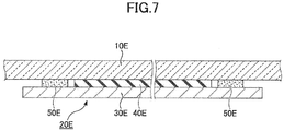
- Fig. 7 is a cross-sectional view of a window plate with vibration damping member according to a sixth embodiment.
- the window plate with vibration damping member according to the sixth embodiment is different from that of the first embodiment in that a compression member is configured with an adhesion layer.
- a compression member is configured with an adhesion layer.
- the window plate with vibration damping member according to the sixth embodiment includes a window plate 10E and a vibration damping member 20E.
- the vibration damping member 20E is attached to the window plate 10E to reduce vibration of the window plate 10E.
- the vibration damping member 20E includes an opposite plate 30E, a viscoelastic layer 40E, and a compression member 50E.
- the opposite plate 30E is provided at one of the surfaces of the window plate 10E, which is opposite the window plate 10E. Similar to the second embodiment, an opposite plate other than the opposite plate 30E may be provided at the other surface of the window plate 10E.
- the viscoelastic layer 40E is provided between the window plate 10E and the opposite plate 30E.
- the viscoelastic layer 40E absorbs vibration of the window plate 10E by deforming viscoelastically.
- the compression member 50E is provided on the surface of the window plate 10E as viewed in the plate thickness direction of the window plate 10E, which restricts movement of the window plate 10E and the opposite plate 30E in the plate thickness direction relative to each other, and compresses the viscoelastic layer 40E in the plate thickness direction. Therefore, similar to the first embodiment described above, design flexibility of the vibration damping member 20E is high, and a good damping property can be ensured.
- the compression member 50E is configured with an adhesion layer for bonding the window plate 10E and the opposite plate 30E together.
- the adhesion layer constituting the compression member 50E may be formed of a resin having higher rigidity than the viscoelastic layer 40E, that is, may be formed of a resin having higher Young's modulus than the viscoelastic layer 40E.
- the adhesion layer constituting the compression member 50E can restrict movement of the window plate 10E and the opposite plate 30E in the plate thickness direction relative to each other by adhesive force of the adhesion layer, and can compress the viscoelastic layer 40E.
- the compression member is configured with one of a unit of a male screw and a female screw, a clip, a rivet, and an adhesion layer.
- the compression member may be configured with multiple parts described above. The combinations are not limited to a specific combination.
- an adhesive layer may be provided between the window plate and the viscoelastic layer for bonding them together.
- an adhesive layer may be provided between the opposite plate and the viscoelastic layer for bonding them together.
- the compression member is configured with an adhesive layer.
- the adhesive layer does not compress the viscoelastic layer in the plate thickness direction, a good damping property can be ensured.
- the reason presumed is that vibration occurring at the window plate 10 is propagated to the opposite plate 30 more easily since the opposite plate is firmly fixed on the glass via the adhesive layer.
Landscapes
- Engineering & Computer Science (AREA)
- Mechanical Engineering (AREA)
- Civil Engineering (AREA)
- Structural Engineering (AREA)
- Vibration Prevention Devices (AREA)
- Vibration Dampers (AREA)
- Bolts, Nuts, And Washers (AREA)
- Buildings Adapted To Withstand Abnormal External Influences (AREA)
Abstract
Description
- The present invention relates to a window plate with vibration damping member, and a vibration damping member.
- A vibration damping member for reducing vibration of window plate has been developed. In Patent Document 1, structures of vibration damping members are disclosed. For example, (1) a structure of a vibration damping member such that a U-shaped metal channel clips a lower side of a window plate via rubber, and (2) a structure of a vibration damping member in which a rubber plate and a metal plate are laminated, are disclosed.
- [PTL 1] Japanese Patent No.
3849453 - However, the following problems exist in the related art. First, (1) if a vibration damping member is configured such that a U-shaped metal channel clips a lower side of a window plate via rubber, the U-shaped channel needs to be placed within a peripheral edge area including an end surface of the window plate. Accordingly, design flexibility was not high.
- Next, (2) the structure in which a rubber plate and a metal plate are laminated does not have sufficient damping property.
- The present invention is made in light of the above problems, and provides a window plate with vibration damping member in which design flexibility of the vibration damping member and damping property are improved.
- According to an aspect of the present invention, there is provision for a window plate with vibration damping member including a window plate to be mounted on a window frame and a vibration damping member for reducing vibration of the window plate. The vibration damping member includes an opposite plate that is provided at one or both surfaces of the window plate so as to be opposite the window plate, a viscoelastic layer provided between the window plate and the opposite plate, and a compression member provided on the surface of the window plate as viewed in a plate thickness direction to compress the viscoelastic layer in the plate thickness direction.
- According to an aspect of the present invention, a window plate with vibration damping member can be provided, in which design flexibility of the vibration damping member and damping property are improved.
- Other objects, features and advantages of the present invention will become more apparent from the following detailed description when read in conjunction with the accompanying drawings.
- [
FIGURE 1 ]
Fig. 1 is a front view of a window plate with vibration damping member according to a first embodiment. - [
FIGURE 2 ]
Fig. 2 is a cross-sectional view of the window plate with vibration damping member taken along a line II-II inFIG. 1 . - [
FIGURE 3 ]
Fig. 3 is a cross-sectional view of a window plate with vibration damping member according to a second embodiment. - [
FIGURE 4 ]
Fig. 4 is a cross-sectional view of a window plate with vibration damping member according to a third embodiment. - [
FIGURE 5 ]
Fig. 5 is a cross-sectional view of a window plate with vibration damping member according to a fourth embodiment. - [
FIGURE 6 ]
Fig. 6 is a cross-sectional view of a window plate with vibration damping member according to a fifth embodiment. - [
FIGURE 7 ]
Fig. 7 is a cross-sectional view of a window plate with vibration damping member according to a sixth embodiment. - In the following, with reference to drawings, embodiments of the present invention will be described. In each drawing, the same reference symbol is assigned to the same component, and redundant explanation will be omitted.
-
Fig. 1 is a front view of a window plate with vibration damping member according to a first embodiment.Fig. 2 is a cross-sectional view of the window plate with vibration damping member taken along a line II-II inFIG. 1 . The window plate with vibration damping member includes awindow plate 10 and avibration damping member 20. - The
window plate 10 is mounted on a window frame. Thewindow plate 10 is mounted, for example, on a window frame of a side door of a car, such that the window plate can be vertically moved between a closed position in which a window of the window frame is closed and an open position in which the window of the window frame is opened. Thewindow plate 10 is formed of a transparent material such as glass or a resin. - Types of the window frame to which the
window plate 10 is to be mounted are not limited to specific ones. Thewindow plate 10 may be mounted on a window frame of a vehicle such as a car or a train, or on a window frame of a building. Further, thewindow plate 10 may be fixed on the window frame such that thewindow plate 10 cannot be moved vertically. When the vehicle or the building on which thewindow plate 10 is mounted vibrates, thewindow plate 10 also vibrates regardless of whether thewindow plate 10 is fixed on the window frame or is mounted on the window frame in a vertically movable state. - The
vibration damping member 20 is attached to thewindow plate 10 to reduce vibration of thewindow plate 10. Thevibration damping member 20 includes anopposite plate 30, aviscoelastic layer 40, and acompression member 50. - The
opposite plate 30 is provided at one of the surfaces of the window plate 10 (interior or exterior of the window plate 10), and is opposite thewindow plate 10. Theopposite plate 30 has higher rigidity than theviscoelastic layer 40. That is, a Young's modulus of theopposite plate 30 is higher than that of theviscoelastic layer 40. Theopposite plate 30 is formed of metal, a resin, or the like. - The
viscoelastic layer 40 is provided between thewindow plate 10 and theopposite plate 30. Theviscoelastic layer 40 absorbs the vibration of thewindow plate 10 by deforming viscoelastically. Theviscoelastic layer 40 is formed of rubber or a resin. Examples of rubber forming theviscoelastic layer 40 are, butadiene rubber, ethylene-propylene-diene rubber, isoprene rubber, chloroprene rubber, nitrile rubber, neoprene rubber, butyl rubber, acrylic rubber, urethane rubber, silicone rubber, and fluororubber, but are not limited to those mentioned here. Also, examples of resin forming theviscoelastic layer 40 are, acrylic resin, urethane resin, and vinyl chloride resin, but are not limited to those mentioned here. Further, theviscoelastic layer 40 may be provided on the whole surface of theopposite plate 30 that is opposite thewindow plate 10, or may be provided on a part of the surface of theopposite plate 30 that is opposite thewindow plate 10. - The
compression member 50 is provided on the surface of thewindow plate 10 as viewed in a plate thickness direction of thewindow plate 10, as illustrated inFIG. 1 . Four units of thecompression members 50 are provided inFIG. 1 , but the number of thecompression members 50 is not limited to four. One ormore compression members 50 should be provided. Thecompression member 50 restricts movement of thewindow plate 10 and theopposite plate 30 in the plate thickness direction relative to each other, and compresses theviscoelastic layer 40 in the plate thickness direction. - According to the present embodiment, the
compression member 50 is provided on the surface of thewindow plate 10 as viewed in the plate thickness direction of thewindow plate 10, and does not protrude beyond the planar area of thewindow plate 10. Therefore, thecompression member 50 is less likely to be affected by the surrounding structure of thewindow plate 10. - In addition, since the
vibration damping member 20 can be arranged on any locations at thewindow plate 10 by using thecompression member 50, the design flexibility of thevibration damping member 20 improves compared with the conventional vibration damping members. Further, if thevibration damping member 20 is provided on the surface of thewindow plate 10 as viewed in the plate thickness direction of thewindow plate 10 so as not to protrude beyond the planar area of thewindow plate 10, thevibration damping member 20 is less likely to be affected by surrounding environment of thewindow plate 10. - Further, since the
compression member 50 compresses theviscoelastic layer 40 in the plate thickness direction of thewindow plate 10, damping property improves. With respect to improving the damping property by compressing theviscoelastic layer 40, the following reasons (1) to (3) may be considered: (1) compressing theviscoelastic layer 40 makes a distance between thewindow plate 10 and theopposite plate 30 shorter, which makes propagation of vibration from thewindow plate 10 to theopposite plate 30 easier, (2) compressing theviscoelastic layer 40 increases hardness of theviscoelastic layer 40, which makes propagation of vibration from thewindow plate 10 to theopposite plate 30 easier, (3) by compressing theviscoelastic layer 40, molecules of theviscoelastic layer 40 are more densely arranged between thewindow plate 10 and theopposite plate 30, which makes propagation of vibration from thewindow plate 10 to theopposite plate 30 easier. - It is desirable that the
compression member 50 compresses theviscoelastic layer 40 in the plate thickness direction of thewindow plate 10, such that thickness of theviscoelastic layer 40 becomes equal to or less than 90% of theviscoelastic layer 40 in a natural state (a state in which no external force is applied to the viscoelastic layer 40). If the thickness of theviscoelastic layer 40 becomes, by compression, equal to or less than 90% of theviscoelastic layer 40 in the natural state, a good damping property can be ensured. Theviscoelastic layer 40 is more preferably compressed such that the thickness becomes equal to or less than 80% of theviscoelastic layer 40 in the natural state, and further more preferably compressed such that the thickness becomes equal to or less than 70% of theviscoelastic layer 40 in the natural state. By controlling the degree of compression of theviscoelastic layer 40, a desired damping property can be ensured. - A through
hole 11 penetrating thewindow plate 10 in the plate thickness direction may be formed in thewindow plate 10 in order that thecompression member 50 is provided on the surface of thewindow plate 10 as viewed in the plate thickness direction of thewindow plate 10, and thecompression member 50 may be inserted in the throughhole 11. - The
compression member 50 includes, for example, amale screw 51 and afemale screw 52 into which themale screw 51 is screwed. Themale screw 51 is fixed to theopposite plate 30 by means of welding, bonding, screwing, inlaying, or the like, and is inserted in the throughhole 11 of thewindow plate 10. Thefemale screw 52 is attached to a tip of themale screw 51. Thefemale screw 52 is disposed on the side opposite theopposite plate 30 with respect to thewindow plate 10. By rotating thefemale screw 52, thewindow plate 10 and theopposite plate 30 can be fastened in the plate thickness direction, thereby theviscoelastic layer 40 can be compressed in the plate thickness direction. - In the present embodiment, the
male screw 51 is fixed to theopposite plate 30. However, in another embodiment, themale screw 51 may be inserted into a through hole (not illustrated in the drawings) that is formed in theopposite plate 30. In a case where themale screw 51 is inserted into a through hole in theopposite plate 30, a flange having a larger diameter than the through hole in theopposite plate 30 may be formed at a -tip of themale screw 51, and the flange may be disposed on the side opposite thewindow plate 10 with respect to theopposite plate 30. When such a structure is adopted, similar to the case described above, thewindow plate 10 and theopposite plate 30 can be fastened in the plate thickness direction by rotating thefemale screw 52, thereby theviscoelastic layer 40 can be compressed in the plate thickness direction. - When the
compression member 50 includes themale screw 51 and thefemale screw 52, thecompression member 50 may also include astopper 54. Thestopper 54 restricts movement of themale screw 51 and thefemale screw 52 in the plate thickness direction of thewindow plate 10 relative to each other. By providing thestopper 54 to thecompression member 50, compressive force of theviscoelastic layer 40 can be managed such that variation in the compressive force, which may occur because of difference of operators during assembly, can be reduced. - The
stopper 54 may be provided on themale screw 51. For example, themale screw 51 may be a stepped screw. Themale screw 51 includes a male screwmain body 53 which is screwed into thefemale screw 52, and astopper 54 having a larger diameter than the male screwmain body 53. Themale screw 51 is fixed to theopposite plate 30, and is inserted into the throughhole 11 of thewindow plate 10. By contacting thefemale screw 52 with thestopper 54 of themale screw 51, movement of thefemale screw 52 in the plate thickness direction relative to themale screw 51 can be restricted. - The
male screw 51 and thefemale screw 52 are formed of metal, but may be formed of a resin so as to reduce damage to thewindow plate 10. - When at least a part of the
compression member 50 is formed of metal, thevibration damping member 20 may include a cushioningmember 70 in order to avoid contacting thewindow plate 10 with the part of thecompression member 50 formed of metal. Provision of the cushioningmember 70 can reduce damage to thewindow plate 10, which is especially effective when thewindow plate 10 is formed of glass. - The cushioning
member 70 is formed of a resin or rubber, similar to theviscoelastic layer 40. The cushioningmember 70 may have viscoelasticity similar to theviscoelastic layer 40, but may have higher rigidity than theviscoelastic layer 40. That is, the cushioningmember 70 may have a higher Young's modulus than theviscoelastic layer 40. Note that theviscoelastic layer 40 may also serve a same role as the cushioningmember 70. - The cushioning
member 70 may enter the throughhole 11 of thewindow plate 10, which can further avoid contacting thewindow plate 10 with thecompression member 50 inside the throughhole 11. The cushioningmember 70 may include acylindrical member 71 surrounding thecompression member 50, so as to surely avoid contacting thewindow plate 10 with thecompression member 50. -
Fig. 3 is a cross-sectional view of a window plate with vibration damping member according to a second embodiment. The window plate with vibration damping member according to the second embodiment is different from that of the first embodiment in that opposite plates and viscoelastic layers are provided on both surfaces of the window plate. In the following, different points will be mainly described. The window plate with vibration damping member according to the second embodiment includes awindow plate 10A and avibration damping member 20A. - The
vibration damping member 20A is attached to thewindow plate 10A to reduce vibration of thewindow plate 10A. Thevibration damping member 20A includesopposite plates viscoelastic layers compression member 50A. - The
opposite plate 30A is provided at one surface of thewindow plate 10A, and is opposite thewindow plate 10A. Also, theopposite plate 31A is provided at the other surface of thewindow plate 10A, which is opposite thewindow plate 10A. Theopposite plates opposite plates opposite plates opposite plates - The
viscoelastic layer 40A is provided between thewindow plate 10A and theopposite plate 30A. On the other side, theviscoelastic layer 41A is provided between thewindow plate 10A and theopposite plate 31A. Theviscoelastic layers window plate 10A by deforming viscoelastically. Theviscoelastic layers viscoelastic layers viscoelastic layers viscoelastic layers - Similar to the first embodiment, the
compression member 50A is provided on the surface of thewindow plate 10A as viewed in the plate thickness direction of thewindow plate 10A, which restricts movement of thewindow plate 10A and theopposite plates viscoelastic layers vibration damping member 20A is high, and a good damping property can be ensured. - A through
hole 11A penetrating thewindow plate 10A in the plate thickness direction may be formed in thewindow plate 10A in order that thecompression member 50A is provided on the surface of thewindow plate 10A as viewed in the plate thickness direction of thewindow plate 10A, and thecompression member 50A may be inserted in the throughhole 11A. - The
compression member 50A includes, for example, amale screw 51A and afemale screw 52A into which themale screw 51A is screwed. Themale screw 51A is fixed to theopposite plate 30A, and is inserted in a throughhole 32A of theopposite plate 31A and in the throughhole 11A of thewindow plate 10A. Thefemale screw 52A is attached to a tip of themale screw 51A. Thefemale screw 52A is disposed on the side opposite thewindow plate 10A with respect to theopposite plate 31A. By rotating thefemale screw 52A, thewindow plate 10A and theopposite plates viscoelastic layers - In the present embodiment, the
male screw 51A is fixed to theopposite plate 30A. However, in another embodiment, themale screw 51A may be inserted into a through hole (not illustrated in the drawings) that is formed in theopposite plate 30A. In a case where themale screw 51A is inserted into a through hole in theopposite plate 30A, a flange having a larger diameter than the through hole in theopposite plate 30A may be formed at a tip of themale screw 51A. The flange may be disposed on the side opposite thewindow plate 10A with respect to theopposite plate 30A. When such a structure is adopted, similar to the case described above, thewindow plate 10A and theopposite plates female screw 52A, thereby theviscoelastic layers - Similar to the first embodiment, the
compression member 50A may include astopper 54A. Thestopper 54A restricts movement of themale screw 51A and thefemale screw 52A in the plate thickness direction of thewindow plate 10A relative to each other. Accordingly, compressive force of theviscoelastic layers window plate 10A can be managed. Thestopper 54A may be provided on themale screw 51A. For example, themale screw 51A may be a stepped screw. Themale screw 51A includes a male screwmain body 53A which is screwed into thefemale screw 52A, and astopper 54A having a larger diameter than the male screwmain body 53A. - When at least a part of the
compression member 50A is formed of metal, thevibration damping member 20A may include a cushioningmember 70A in order to avoid contacting thewindow plate 10A with the part of thecompression member 50A formed of metal. Provision of the cushioningmember 70A can reduce damage to thewindow plate 10A, which is especially effective when thewindow plate 10A is formed of glass. - The cushioning
member 70A may enter the throughhole 11A of thewindow plate 10A, which can further avoid contacting thewindow plate 10A with thecompression member 50A inside the throughhole 11A. The cushioningmember 70A may include acylindrical member 71A surrounding thecompression member 50A inside the throughhole 11A, so as to surely avoid contacting thewindow plate 10A with thecompression member 50A. -
Fig. 4 is a cross-sectional view of a window plate with vibration damping member according to a third embodiment. The window plate with vibration damping member according to the third embodiment is different from that of the first embodiment in that a stopper is provided on a female screw. In the following, different points will be mainly described. The window plate with vibration damping member according to the third embodiment includes awindow plate 10B and avibration damping member 20B. - The
vibration damping member 20B is attached to thewindow plate 10B to reduce vibration of thewindow plate 10B. Thevibration damping member 20B includes anopposite plate 30B, aviscoelastic layer 40B, and acompression member 50B. - The
opposite plate 30B is provided at one of the surfaces of thewindow plate 10B, and is opposite thewindow plate 10B. Similar to the second embodiment, a opposite plate other than theopposite plate 30B may be provided at the other surface of thewindow plate 10B. - The
viscoelastic layer 40B is provided between thewindow plate 10B and theopposite plate 30B. Theviscoelastic layer 40B absorbs vibration of thewindow plate 10B by deforming viscoelastically. - Similar to the first embodiment, the
compression member 50B is provided on the surface of thewindow plate 10B as viewed in the plate thickness direction of thewindow plate 10B, which restricts movement of thewindow plate 10B and theopposite plate 30B in the plate thickness direction relative to each other, and compresses theviscoelastic layer 40B in the plate thickness direction. Therefore, similar to the first embodiment described above, design flexibility of thevibration damping member 20B is high, and a good damping property can be ensured. - A through
hole 11B penetrating thewindow plate 10B in the plate thickness direction may be formed in thewindow plate 10B in order that thecompression member 50B is provided on the surface of thewindow plate 10B as viewed in the plate thickness direction of thewindow plate 10B, and thecompression member 50B may be inserted in the throughhole 11B. - The
compression member 50B includes, for example, amale screw 51B and afemale screw 52B into which themale screw 51B is screwed. Themale screw 51B is fixed to theopposite plate 30B, and is inserted in the throughhole 11B of thewindow plate 10B. Thefemale screw 52B is attached to a tip of themale screw 51B. By rotating thefemale screw 52B, thewindow plate 10B and theopposite plate 30B can be fastened in the plate thickness direction, thereby theviscoelastic layer 40B can be compressed in the plate thickness direction. - In the present embodiment, the
male screw 51B is fixed to theopposite plate 30B. However, in another embodiment, themale screw 51B may be inserted into a through hole (not illustrated in the drawings) that is formed on theopposite plate 30B. In a case where themale screw 51B is inserted into a through hole on theopposite plate 30B, a flange having a larger diameter than the through hole on theopposite plate 30B may be formed at a tip of themale screw 51B. The flange may be disposed on the side opposite thewindow plate 10B with respect to theopposite plate 30B. When such a structure is adopted, similar to the case described above, thewindow plate 10B and theopposite plate 30B can be fastened in the plate thickness direction by rotating thefemale screw 52B, thereby theviscoelastic layer 40B can be compressed in the plate thickness direction. - The
compression member 50B may include astopper 54B. Thestopper 54B restricts movement of themale screw 51B and thefemale screw 52B in the plate thickness direction of thewindow plate 10B relative to each other. Accordingly, compressive force of theviscoelastic layer 40B can be managed. - The
stopper 54B may be provided on thefemale screw 52B. Thefemale screw 52B includes a female screwmain body 53B having a larger diameter than the throughhole 11B of thewindow plate 10B, and thestopper 54B having a smaller diameter than the throughhole 11B of thewindow plate 10B. The female screwmain body 53B is disposed on the side opposite theopposite plate 30B with respect to thewindow plate 10B, and is screwed into themale screw 51B. Thestopper 54B is also screwed into themale screw 51B. But in another embodiment, thestopper 54B may not be screwed into themale screw 51B. By inserting thestopper 54B into the throughhole 11B of thewindow plate 10B and by contacting thestopper 54B with theopposite plate 30B, movement of thefemale screw 52B in the plate thickness direction relative to themale screw 51B can be restricted. - If the
female screw 52B is inserted in the throughhole 11B and that thestopper 54B can be screwed into themale screw 51B as described in the present embodiment, themale screw 51B is not necessarily inserted in the throughhole 11B. - When at least a part of the
compression member 50B is formed of metal, thevibration damping member 20B may include a cushioningmember 70B in order to avoid contacting thewindow plate 10B with the part of thecompression member 50B formed of metal. Provision of the cushioningmember 70B can reduce damage to thewindow plate 10B, which is especially effective when thewindow plate 10B is formed of glass. - The cushioning
member 70B may enter the throughhole 11B of thewindow plate 10B, which can further avoid contacting thewindow plate 10B with thecompression member 50B inside the throughhole 11B. The cushioningmember 70B may include acylindrical member 71B surrounding thecompression member 50B inside the throughhole 11B, so as to surely avoid contacting thewindow plate 10B with thecompression member 50B. -
Fig. 5 is a cross-sectional view of a window plate with vibration damping member according to a fourth embodiment. The window plate with vibration damping member according to the fourth embodiment is different from that of the first embodiment in that arrangement of a male screw and a female screw is opposite to the arrangement in the first embodiment. In the following, different points will be mainly described. The window plate with vibration damping member according to the fourth embodiment includes awindow plate 10C and a vibration damping member 20C. - The vibration damping member 20C is attached to the
window plate 10C to reduce vibration of thewindow plate 10C. The vibration damping member 20C includes anopposite plate 30C, aviscoelastic layer 40C, and acompression member 50C. - The
opposite plate 30C is provided at one of the surfaces of thewindow plate 10C, and is opposite thewindow plate 10C. Similar to the second embodiment, an opposite plate other than theopposite plate 30C may be provided at the other surface of thewindow plate 10C. - The
viscoelastic layer 40C is provided between thewindow plate 10C and theopposite plate 30C. Theviscoelastic layer 40C absorbs vibration of thewindow plate 10C by deforming viscoelastically. - Similar to the first embodiment, the
compression member 50C is provided on the surface of thewindow plate 10C as viewed in the plate thickness direction of thewindow plate 10C, which restricts movement of thewindow plate 10C and theopposite plate 30C in the plate thickness direction relative to each other, and compresses theviscoelastic layer 40C in the plate thickness direction. Therefore, similar to the first embodiment described above, design flexibility of the vibration damping member 20C is high, and a good damping property can be ensured. - A through hole 11C penetrating the window plate 1OC in the plate thickness direction may be formed on the
window plate 10C in order that thecompression member 50C is provided on the surface of thewindow plate 10C as viewed in the plate thickness direction of thewindow plate 10C, and thecompression member 50C may be inserted in the through hole 11C. - The
compression member 50C includes, for example, amale screw 51C and afemale screw 52C into which themale screw 51C is screwed. Thefemale screw 52C is fixed to theopposite plate 30C, and is inserted in the through hole 11C of thewindow plate 10C. By rotating themale screw 51C while themale screw 51C is being screwed intofemale screw 52C, thewindow plate 10C and theopposite plate 30C can be fastened in the plate thickness direction, thereby theviscoelastic layer 40C can be compressed in the plate thickness direction. - In the present embodiment, the
female screw 52C is fixed to theopposite plate 30C. However, in another embodiment, thefemale screw 52C may not be fixed to theopposite plate 30C. When thefemale screw 52C is not fixed to theopposite plate 30C, a screw hole may be formed in theopposite plate 30C and themale screw 51C may be screwed into the screw hole. When such a structure is adopted, similar to the case described above, thewindow plate 10C and theopposite plate 30C can be fastened in the plate thickness direction by rotating themale screw 51C, thereby theviscoelastic layer 40C can be compressed in the plate thickness direction. On the other hand, when thefemale screw 52C is fixed to theopposite plate 30C, a screw hole may or may not be formed in theopposite plate 30C. Additionally, a cylindrical bore may be formed instead of a screw hole. A screw hole or a cylindrical bore is formed when themale screw 51C (more specifically, a male screwmain body 53C that will be described later) is long. - The
compression member 50C may include astopper 54C. Thestopper 54C restricts movement of themale screw 51C and thefemale screw 52C in the plate thickness direction of thewindow plate 10C relative to each other. Accordingly, compressive force of theviscoelastic layer 40C can be managed. - The
stopper 54C may be provided on themale screw 51C. Themale screw 51C includes a male screwmain body 53C which is screwed into thefemale screw 52C, and thestopper 54C having a larger diameter than the male screwmain body 53C. Thestopper 54C is disposed on the side opposite theopposite plate 30C with respect to thewindow plate 10C. By contacting thestopper 54C with thefemale screw 52C, movement of themale screw 51C in the plate thickness direction relative to thefemale screw 52C can be restricted. - In the present embodiment, the
stopper 54C is provided on themale screw 51C, but in another embodiment, thestopper 54C may be provided on the female screw, similar to thestopper 54B in the third embodiment. - When at least a part of the
compression member 50C is formed of metal, the vibration damping member 20C may include a cushioningmember 70C in order to avoid contacting thewindow plate 10C with the part of thecompression member 50C formed of metal. Provision of the cushioningmember 70C can reduce damage to thewindow plate 10C, which is especially effective when thewindow plate 10C is formed of glass. - The cushioning
member 70C may enter the through hole 11C of thewindow plate 10C, which can further avoid contacting thewindow plate 10C with thecompression member 50C inside the through hole 11C. The cushioningmember 70C may include acylindrical member 71C surrounding thecompression member 50C inside the through hole 11C, so as to surely avoid contacting thewindow plate 10C with thecompression member 50C. -
Fig. 6 is a cross-sectional view of a window plate with vibration damping member according to a fifth embodiment. The window plate with vibration damping member according to the fifth embodiment is different from that of the first embodiment in that a vibration damping member is configured with a clip. In the following, different points will be mainly described. The window plate with vibration damping member according to the fifth embodiment includes awindow plate 10D and avibration damping member 20D. - The
vibration damping member 20D is attached to thewindow plate 10D to reduce vibration of thewindow plate 10D. Thevibration damping member 20D includes anopposite plate 30D, aviscoelastic layer 40D, and acompression member 50D. - The
opposite plate 30D is provided at one of the surfaces of thewindow plate 10D, and is opposite thewindow plate 10D. Similar to the second embodiment, an opposite plate other than theopposite plate 30D may be provided at the other surface of thewindow plate 10D. - The
viscoelastic layer 40D is provided between thewindow plate 10D and theopposite plate 30D. Theviscoelastic layer 40D absorbs vibration of thewindow plate 10D by deforming viscoelastically. - Similar to the first embodiment, the
compression member 50D is provided on the surface of thewindow plate 10D as viewed in the plate thickness direction of thewindow plate 10D, which restricts movement of thewindow plate 10D and theopposite plate 30D in the plate thickness direction relative to each other, and compresses theviscoelastic layer 40D in the plate thickness direction. Therefore, similar to the first embodiment described above, design flexibility of thevibration damping member 20D is high, and a good damping property can be ensured. - A through
hole 11D penetrating thewindow plate 10D in the plate thickness direction may be formed in thewindow plate 10D in order that thecompression member 50D is provided on the surface of thewindow plate 10D as viewed in the plate thickness direction of the window plate 10b, and thecompression member 50D may be inserted in the throughhole 11D. - The
compression member 50D is, for example, configured with a clip, which includes aspindle 55D and anelastic member 56D. Thespindle 55D is fixed on theopposite plate 30D, and is inserted in the throughhole 11D of thewindow plate 10D. Theelastic member 56D is provided on a tip of thespindle 55D, and is disposed on the side opposite theopposite plate 30D with respect to thewindow plate 10D. - A
presser plate 57D may be disposed between theelastic member 56D and thewindow plate 10D to press thewindow plate 10D. Aninsertion hole 58D is formed in thepresser plate 57D, and theelastic member 56D is inserted in theinsertion hole 58D. Theelastic member 56D deforms elastically while passing through theinsertion hole 58D, and starts restoring elastically after passing theinsertion hole 58D. - In the present embodiment, the
presser plate 57D is disposed between theelastic member 56D and thewindow plate 10D, but in another embodiment, thepresser plate 57D may not be provided and theelastic member 56D may directly touch thewindow plate 10D. If such a configuration is adopted, theelastic member 56D deforms elastically while passing through the throughhole 11D of thewindow plate 10D, and starts restoring elastically after passing the throughhole 11D. - Further, if the
presser plate 57D is used, theelastic member 56D does not need to deform elastically while passing through the throughhole 11D of the window plate 100. In this case, the diameter of the throughhole 11D may be larger than that of theelastic member 56D in the natural state. By adopting such a configuration, a scratch on thewindow plate 10D is less likely to be made. - By elastic restoring force of the
elastic member 56D, theelastic member 56D can restrict movement of thewindow plate 10D and theopposite plate 30D in the plate thickness direction relative to each other, and compress theviscoelastic layer 40D. Compressive force of theviscoelastic layer 40D can be managed by appropriately selecting size or shape of theelastic member 56D, or length of thespindle 55D. - The
elastic members 56D may be arranged symmetrically with respect to thespindle 55D. For example, theelastic members 56D are symmetrically arranged on both sides of thespindle 55D. In this arrangement, since elastic restoring force occurs symmetrically with respect to thespindle 55D, good stability can be ensured. The number of theelastic members 56D is not limited to 2. More than twoelastic members 56D may be provided. More than twoelastic members 56D may be arranged around thespindle 55D at regular intervals. Alternatively, only oneelastic member 56D may be provided. When oneelastic member 56D is provided, theelastic member 56D may have a symmetrical shape centered on thespindle 55D. - In the present embodiment, the
spindle 55D is fixed on theopposite plate 30D. But in another embodiment, thespindle 55D may be inserted in a through hole (not illustrated in the drawings) formed in theopposite plate 30D. In a case where thespindle 55D is inserted in the through hole in theopposite plate 30D, a flange having a larger diameter than the through hole in theopposite plate 30D may be formed at a tip of thespindle 55D. The flange may be disposed on the side opposite thewindow plate 10D with respect to theopposite plate 30D. When such a structure is adopted, similar to the case described above, by the elastic restoring force of theelastic member 56D, theelastic member 56D can restrict movement of thewindow plate 10D and theopposite plate 30D in the plate thickness direction relative to each other, and compress theviscoelastic layer 40D. - The
spindle 55D and theelastic member 56D are formed of a resin so as to reduce damage to thewindow plate 10D. But in another embodiment, thespindle 55D and theelastic member 56D may be formed of metal to increase the elastic restoring force. - When at least a part of the
compression member 50D is formed of metal, thevibration damping member 20D may include a cushioning member that is not illustrated in the drawings in order to avoid contacting thewindow plate 10D with the part of thecompression member 50D formed of metal. Provision of the cushioning member can reduce damage to thewindow plate 10D, which is especially effective when thewindow plate 10D is formed of glass. The cushioning member may serve a same role as thepresser plate 57D. - Similar to the first embodiment, the cushioning member may enter the through
hole 11D, which can further avoid contacting thewindow plate 10D with thecompression member 50D inside the throughhole 11D. The cushioning member may include a cylindrical member surrounding thecompression member 50D inside the throughhole 11D, so as to surely avoid contacting thewindow plate 10D with thecompression member 50D. - In the present embodiment, the
compression member 50D is configured with a clip. But in another embodiment, thecompression member 50D may be configured with a rivet having a deformable shaft whose tail can be plastically deformed. The deformable shaft may be a solid shaft, or a tubular shaft. When the tubular shaft is used as the deformable shaft, a mandrel may be provided in the deformable shaft. By pulling the mandrel, the tail of the deformable shaft is plastically deformed. The deformable shaft is fixed on theopposite plate 30D, and is inserted in the throughhole 11D of thewindow plate 10D. The tail of the deformable shaft is plastically deformed after the deformable shaft is inserted in the throughhole 11D, to restrict movement of thewindow plate 10D and theopposite plate 30D in the plate thickness direction relative to each other, and to compress theviscoelastic layer 40D in the plate thickness direction. -
Fig. 7 is a cross-sectional view of a window plate with vibration damping member according to a sixth embodiment. The window plate with vibration damping member according to the sixth embodiment is different from that of the first embodiment in that a compression member is configured with an adhesion layer. In the following, different points will be mainly described. The window plate with vibration damping member according to the sixth embodiment includes awindow plate 10E and avibration damping member 20E. - The
vibration damping member 20E is attached to thewindow plate 10E to reduce vibration of thewindow plate 10E. Thevibration damping member 20E includes anopposite plate 30E, aviscoelastic layer 40E, and acompression member 50E. - The
opposite plate 30E is provided at one of the surfaces of thewindow plate 10E, which is opposite thewindow plate 10E. Similar to the second embodiment, an opposite plate other than theopposite plate 30E may be provided at the other surface of thewindow plate 10E. - The
viscoelastic layer 40E is provided between thewindow plate 10E and theopposite plate 30E. Theviscoelastic layer 40E absorbs vibration of thewindow plate 10E by deforming viscoelastically. - Similar to the first embodiment, the
compression member 50E is provided on the surface of thewindow plate 10E as viewed in the plate thickness direction of thewindow plate 10E, which restricts movement of thewindow plate 10E and theopposite plate 30E in the plate thickness direction relative to each other, and compresses theviscoelastic layer 40E in the plate thickness direction. Therefore, similar to the first embodiment described above, design flexibility of thevibration damping member 20E is high, and a good damping property can be ensured. - The
compression member 50E is configured with an adhesion layer for bonding thewindow plate 10E and theopposite plate 30E together. The adhesion layer constituting thecompression member 50E may be formed of a resin having higher rigidity than theviscoelastic layer 40E, that is, may be formed of a resin having higher Young's modulus than theviscoelastic layer 40E. The adhesion layer constituting thecompression member 50E can restrict movement of thewindow plate 10E and theopposite plate 30E in the plate thickness direction relative to each other by adhesive force of the adhesion layer, and can compress theviscoelastic layer 40E. - As described above, the preferred embodiments and the like for the window plate with vibration damping member have been described. However, the present invention is not limited to the above-described specific embodiments, but various variations and modifications may be made without deviating from the scope of the present invention, described in claims.
- For example, in the embodiments described above, the compression member is configured with one of a unit of a male screw and a female screw, a clip, a rivet, and an adhesion layer. However, the compression member may be configured with multiple parts described above. The combinations are not limited to a specific combination.
- Further, in
FIGS. 2 through 7 , an adhesive layer may be provided between the window plate and the viscoelastic layer for bonding them together. In addition, an adhesive layer may be provided between the opposite plate and the viscoelastic layer for bonding them together. - In the sixth embodiment, an example is described that the compression member is configured with an adhesive layer. In this configuration, even if the adhesive layer does not compress the viscoelastic layer in the plate thickness direction, a good damping property can be ensured. The reason presumed is that vibration occurring at the
window plate 10 is propagated to theopposite plate 30 more easily since the opposite plate is firmly fixed on the glass via the adhesive layer. - The present application is based on and claims the benefit of priority of Japanese Patent Application No.
2015-106394 filed on May 26, 2015 -
- 10
- window plate
- 11
- through hole
- 20
- vibration damping member
- 30
- opposite plate
- 40
- viscoelastic layer
- 50
- compression member
- 51
- male screw
- 52
- female screw
- 54
- stopper
- 70
- cushioning member
- 50D
- compression member
- 55D
- spindle
- 56D
- elastic member
- 57D
- presser plate
- 50E
- compression member (adhesion layer)
Claims (15)
- A window plate with vibration damping member comprising a window plate to be mounted on a window frame and a vibration damping member for reducing vibration of the window plate, the vibration damping member comprising:an opposite plate provided at one or both surfaces of the window plate so as to be opposite the window plate;a viscoelastic layer provided between the window plate and the opposite plate; anda compression member provided on the surface of the window plate as viewed in a plate thickness direction to compress the viscoelastic layer in the plate thickness direction.
- The window plate with vibration damping member according to claim 1, wherein a through hole penetrating the window plate in the plate thickness direction is formed in the window plate, and the compression member is inserted in the through hole.
- The window plate with vibration damping member according to claim 2, wherein the compression member comprises a male screw and a female screw into which the male screw is screwed, and at least one of the male screw and the female screw is inserted in the through hole.
- The window plate with vibration damping member according to claim 3, wherein the compression member comprises a stopper configured to restrict movement of the male screw and the female screw in the plate thickness direction relative to each other.
- The window plate with vibration damping member according to any one of claims 2 to 4, wherein the compression member comprises a spindle to be inserted in the through hole and an elastic member provided on a tip of the spindle, the elastic member being configured, by elastic restoring force of the elastic member, to restrict movement of the window plate and the opposite plate in the plate thickness direction relative to each other, and to compress the viscoelastic layer in the plate thickness direction.
- The window plate with vibration damping member according to any one of claims 2 to 5, wherein a part of the compression member is formed of metal, and the vibration damping member comprises a cushioning member to avoid contacting the window plate with the part of the compression member.
- The window plate with vibration damping member according to claim 6, wherein the cushioning member is configured to enter the through hole.
- The window plate with vibration damping member according to any one of claims 1 to 7, wherein the compression member comprises an adhesion layer to bond the window plate and the opposite plate together.
- A vibration damping member for reducing vibration of a window plate to be mounted on a window frame, the vibration damping member comprising:an opposite plate provided at one or both surfaces of the window plate so as to be opposite the window plate;a viscoelastic layer provided between the window plate and the opposite plate; anda compression member provided on the surface of the window plate as viewed in a plate thickness direction to compress the viscoelastic layer in the plate thickness direction.
- The vibration damping member according to claim 9, wherein the compression member is inserted in a through hole formed on the window plate, the through hole penetrating the window plate in the plate thickness direction.
- The vibration damping member according to claim 10, wherein the compression member comprises a male screw and a female screw into which the male screw is screwed, and at least one of the male screw and the female screw is inserted in the through hole.
- The vibration damping member according to claim 11, wherein the compression member comprises a stopper configured to restrict movement of the male screw and the female screw in the plate thickness direction relative to each other.
- The vibration damping member according to any one of claims 10 to 12, wherein the compression member comprises a spindle to be inserted in the through hole and an elastic member provided on a tip of the spindle, the elastic member being configured, by elastic restoring force of the elastic member, to restrict movement of the window plate and the opposite plate in the plate thickness direction relative to each other, and to compress the viscoelastic layer in the plate thickness direction.
- The vibration damping member according to any one of claims 10 to 13, wherein a part of the compression member is formed of metal, and the vibration damping member comprises a cushioning member to avoid contacting the window plate with the part of the compression member.
- The vibration damping member according to claim 14, wherein the cushioning member is configured to enter the through hole.
Applications Claiming Priority (2)
| Application Number | Priority Date | Filing Date | Title |
|---|---|---|---|
| JP2015106394 | 2015-05-26 | ||
| PCT/JP2016/064129 WO2016190119A1 (en) | 2015-05-26 | 2016-05-12 | Vibration-damping-member-equipped window plate, and vibration damping member |
Publications (2)
| Publication Number | Publication Date |
|---|---|
| EP3306025A1 true EP3306025A1 (en) | 2018-04-11 |
| EP3306025A4 EP3306025A4 (en) | 2019-02-20 |
Family
ID=57392713
Family Applications (1)
| Application Number | Title | Priority Date | Filing Date |
|---|---|---|---|
| EP16799827.7A Withdrawn EP3306025A4 (en) | 2015-05-26 | 2016-05-12 | WINDOW PLATE EQUIPPED WITH VIBRATION DAMPING ELEMENT AND VIBRATION DAMPING ELEMENT |
Country Status (5)
| Country | Link |
|---|---|
| US (1) | US20180094470A1 (en) |
| EP (1) | EP3306025A4 (en) |
| JP (1) | JPWO2016190119A1 (en) |
| CN (1) | CN107614822A (en) |
| WO (1) | WO2016190119A1 (en) |
Cited By (1)
| Publication number | Priority date | Publication date | Assignee | Title |
|---|---|---|---|---|
| EP3222451B1 (en) * | 2016-03-23 | 2019-03-06 | AGC Inc. | Window plate for vehicle |
Families Citing this family (3)
| Publication number | Priority date | Publication date | Assignee | Title |
|---|---|---|---|---|
| CN205755147U (en) * | 2016-05-20 | 2016-11-30 | 中兴通讯股份有限公司 | A kind of shell structure and terminal unit |
| US10500930B2 (en) * | 2018-01-08 | 2019-12-10 | Toyota Motor Engineering & Manufacturing North America, Inc. | Vehicle door glass damping and vehicles including vehicle door glass damping systems |
| KR102689066B1 (en) * | 2023-12-19 | 2024-07-26 | 주식회사 큐원 | Base Isolation Floor System |
Family Cites Families (16)
| Publication number | Priority date | Publication date | Assignee | Title |
|---|---|---|---|---|
| DE2528705A1 (en) * | 1975-06-27 | 1977-01-13 | Kloeckner Humboldt Deutz Ag | Elastic securing bolt for windscreen - having rivet shaped stud with spreading end to secure glass |
| DE4437532C2 (en) * | 1994-10-20 | 1996-12-12 | Brose Fahrzeugteile | Device for connecting a window lifter to the sliding window pane of a motor vehicle |
| JP3870294B2 (en) * | 2001-10-19 | 2007-01-17 | 株式会社ニフコ | Glass holder |
| US20040111970A1 (en) * | 2002-04-18 | 2004-06-17 | Fenelon Paul J. | Window lift mechanism |
| DE102004003712A1 (en) * | 2004-01-24 | 2005-08-18 | Daimlerchrysler Ag | Vibration damping system for sliding windows in vehicles comprises rubber disks mounted between inner side of window and wall of shaft in which it slides and which fit into slots in wall |
| WO2009069899A2 (en) * | 2007-11-26 | 2009-06-04 | Donghwa Tech Co. | Door glass grip for vehicle |
| JP5382710B2 (en) * | 2009-08-26 | 2014-01-08 | 株式会社ニフコ | Glass holder |
| CN103648813B (en) * | 2011-07-11 | 2016-05-18 | 百乐仕株式会社 | Vibration prevention device for vehicle opening and closing body and stopper for vehicle opening and closing body |
| FR2988420B1 (en) * | 2012-03-26 | 2014-11-21 | Inteva Products France Sas | METHOD OF ASSEMBLING A GLASS AND A GLASS HOLDER, ASSEMBLED TOGETHER AND READY TO BE ASSEMBLED |
| DE102012102795B4 (en) * | 2012-03-30 | 2013-11-21 | Küster Holding GmbH | Fastening device for fastening a window pane within a vehicle body of a motor vehicle |
| EP2657440A1 (en) * | 2012-04-24 | 2013-10-30 | Grupo Antolin-Ingenieria, S.A. | Attachment device for attaching a glass pane of a vehicle to a carrier of a window regulator of a vehicle, glass pane assembly, window regulator assembly, and process of assembling and disassembling |
| US20160263968A1 (en) * | 2015-03-10 | 2016-09-15 | Ford Global Technologies, Llc | Adjustable door glass attachment bracket |
| US10773485B2 (en) * | 2015-11-17 | 2020-09-15 | Saint-Gobain Glass France | Composite glass pane with a mounting hole |
| WO2018068873A1 (en) * | 2016-10-13 | 2018-04-19 | Advanced Comfort Systems France Sas - Acs France | Window-raising device for a motor vehicle, corresponding motor vehicle door and assembly method |
| US10487558B2 (en) * | 2017-03-15 | 2019-11-26 | Ford Global Technologies, Llc | Bonding bracket for an operable vehicle window having a partially open adhesive channel |
| JP7147484B2 (en) * | 2017-12-08 | 2022-10-05 | Agc株式会社 | Window glass with holder and manufacturing method thereof |
-
2016
- 2016-05-12 JP JP2017520620A patent/JPWO2016190119A1/en active Pending
- 2016-05-12 EP EP16799827.7A patent/EP3306025A4/en not_active Withdrawn
- 2016-05-12 WO PCT/JP2016/064129 patent/WO2016190119A1/en not_active Ceased
- 2016-05-12 CN CN201680029665.2A patent/CN107614822A/en not_active Withdrawn
-
2017
- 2017-11-10 US US15/809,047 patent/US20180094470A1/en not_active Abandoned
Cited By (1)
| Publication number | Priority date | Publication date | Assignee | Title |
|---|---|---|---|---|
| EP3222451B1 (en) * | 2016-03-23 | 2019-03-06 | AGC Inc. | Window plate for vehicle |
Also Published As
| Publication number | Publication date |
|---|---|
| JPWO2016190119A1 (en) | 2018-03-15 |
| US20180094470A1 (en) | 2018-04-05 |
| WO2016190119A1 (en) | 2016-12-01 |
| EP3306025A4 (en) | 2019-02-20 |
| CN107614822A (en) | 2018-01-19 |
Similar Documents
| Publication | Publication Date | Title |
|---|---|---|
| US20180094470A1 (en) | Window plate with vibration damping member, and vibration damping member | |
| EP2607128A2 (en) | Seal member of automobile door | |
| CN103129496A (en) | Supporting structure of door impact beam for vehicle | |
| EP3135518B1 (en) | Automobile beltline portion sound insulating structure and automobile door glass | |
| US9689184B2 (en) | Door outside handle for vehicle | |
| CN104160171B (en) | For damping stop member of rotation of two parts that damping is connected by joint pin and application thereof and associated vehicle | |
| US20170210275A1 (en) | Passenger compartment illumination device | |
| CN108252995A (en) | Component mounting structure and installs fixture | |
| CN105705398A (en) | Sliding door sealing member, and vehicle | |
| JP2017089247A (en) | Door-nipping detector | |
| KR20080001559A (en) | Hatch fixture assembly and method for reducing the impact of an explosion storm | |
| US9311832B2 (en) | Plate-like member mounting device | |
| MX2007002992A (en) | Acoustic damping section which is disposed between a window panel and the body of a vehicle. | |
| JP2009126290A (en) | Roof device | |
| CN106394191B (en) | Sound insulation structure of the waistline of automobiles and door glass for automobiles | |
| JP6368629B2 (en) | Railway vehicle | |
| CN106470933A (en) | The doorway device of elevator | |
| CN105091470B (en) | Refrigerator doors and the refrigerator for having the refrigerator doors | |
| CN215671890U (en) | Window arrangement and structure including walls | |
| JP6235845B2 (en) | Railway vehicle advertising space | |
| CN106394206A (en) | Automobile beltline portion sound insulating structure and automobile door glass | |
| JP7773022B2 (en) | Partition structure | |
| JP5724457B2 (en) | Body structure | |
| US9713951B2 (en) | Window trim for use with a fixed window of a vehicle | |
| JP6217913B2 (en) | Vehicle sliding door structure |
Legal Events
| Date | Code | Title | Description |
|---|---|---|---|
| PUAI | Public reference made under article 153(3) epc to a published international application that has entered the european phase |
Free format text: ORIGINAL CODE: 0009012 |
|
| 17P | Request for examination filed |
Effective date: 20171120 |
|
| AK | Designated contracting states |
Kind code of ref document: A1 Designated state(s): AL AT BE BG CH CY CZ DE DK EE ES FI FR GB GR HR HU IE IS IT LI LT LU LV MC MK MT NL NO PL PT RO RS SE SI SK SM TR |
|
| AX | Request for extension of the european patent |
Extension state: BA ME |
|
| DAV | Request for validation of the european patent (deleted) | ||
| DAX | Request for extension of the european patent (deleted) | ||
| RAP1 | Party data changed (applicant data changed or rights of an application transferred) |
Owner name: AGC INC. |
|
| A4 | Supplementary search report drawn up and despatched |
Effective date: 20190123 |
|
| RIC1 | Information provided on ipc code assigned before grant |
Ipc: B60J 1/10 20060101ALI20190117BHEP Ipc: E05F 11/38 20060101ALI20190117BHEP Ipc: E06B 7/28 20060101ALI20190117BHEP Ipc: E06B 3/54 20060101AFI20190117BHEP |
|
| STAA | Information on the status of an ep patent application or granted ep patent |
Free format text: STATUS: THE APPLICATION IS DEEMED TO BE WITHDRAWN |
|
| 18D | Application deemed to be withdrawn |
Effective date: 20190820 |