EP3305735A1 - Optical fiber production method - Google Patents
Optical fiber production method Download PDFInfo
- Publication number
- EP3305735A1 EP3305735A1 EP16894557.4A EP16894557A EP3305735A1 EP 3305735 A1 EP3305735 A1 EP 3305735A1 EP 16894557 A EP16894557 A EP 16894557A EP 3305735 A1 EP3305735 A1 EP 3305735A1
- Authority
- EP
- European Patent Office
- Prior art keywords
- optical fiber
- temperature
- glass
- core
- glass forming
- Prior art date
- Legal status (The legal status is an assumption and is not a legal conclusion. Google has not performed a legal analysis and makes no representation as to the accuracy of the status listed.)
- Granted
Links
Images



Classifications
-
- C—CHEMISTRY; METALLURGY
- C03—GLASS; MINERAL OR SLAG WOOL
- C03B—MANUFACTURE, SHAPING, OR SUPPLEMENTARY PROCESSES
- C03B37/00—Manufacture or treatment of flakes, fibres, or filaments from softened glass, minerals, or slags
- C03B37/01—Manufacture of glass fibres or filaments
- C03B37/02—Manufacture of glass fibres or filaments by drawing or extruding, e.g. direct drawing of molten glass from nozzles; Cooling fins therefor
- C03B37/025—Manufacture of glass fibres or filaments by drawing or extruding, e.g. direct drawing of molten glass from nozzles; Cooling fins therefor from reheated softened tubes, rods, fibres or filaments, e.g. drawing fibres from preforms
-
- C—CHEMISTRY; METALLURGY
- C03—GLASS; MINERAL OR SLAG WOOL
- C03B—MANUFACTURE, SHAPING, OR SUPPLEMENTARY PROCESSES
- C03B37/00—Manufacture or treatment of flakes, fibres, or filaments from softened glass, minerals, or slags
- C03B37/01—Manufacture of glass fibres or filaments
- C03B37/02—Manufacture of glass fibres or filaments by drawing or extruding, e.g. direct drawing of molten glass from nozzles; Cooling fins therefor
- C03B37/025—Manufacture of glass fibres or filaments by drawing or extruding, e.g. direct drawing of molten glass from nozzles; Cooling fins therefor from reheated softened tubes, rods, fibres or filaments, e.g. drawing fibres from preforms
- C03B37/027—Fibres composed of different sorts of glass, e.g. glass optical fibres
- C03B37/02718—Thermal treatment of the fibre during the drawing process, e.g. cooling
- C03B37/02727—Annealing or re-heating
-
- C—CHEMISTRY; METALLURGY
- C03—GLASS; MINERAL OR SLAG WOOL
- C03B—MANUFACTURE, SHAPING, OR SUPPLEMENTARY PROCESSES
- C03B37/00—Manufacture or treatment of flakes, fibres, or filaments from softened glass, minerals, or slags
- C03B37/10—Non-chemical treatment
-
- G—PHYSICS
- G02—OPTICS
- G02B—OPTICAL ELEMENTS, SYSTEMS OR APPARATUS
- G02B6/00—Light guides; Structural details of arrangements comprising light guides and other optical elements, e.g. couplings
- G02B6/02—Optical fibres with cladding with or without a coating
-
- C—CHEMISTRY; METALLURGY
- C03—GLASS; MINERAL OR SLAG WOOL
- C03B—MANUFACTURE, SHAPING, OR SUPPLEMENTARY PROCESSES
- C03B2205/00—Fibre drawing or extruding details
- C03B2205/56—Annealing or re-heating the drawn fibre prior to coating
Definitions
- the present invention relates to an optical fiber production method.
- optical fiber communication systems in order to increase the reach and the rate of optical transmission, the optical signal-to-noise ratio has to be increased. Thus, a decrease in transmission losses in optical fibers is demanded.
- transmission losses caused by impurities contained in optical fibers are closed to the lower limits.
- a remaining main cause of transmission losses is scattering losses in association with fluctuations in the structure or composition of glass forming optical fibers. This is inevitable, because optical fibers are formed of glass.
- a method is known to cool molten glass slowly.
- a method of slowly cooling molten glass an attempt is made to slowly cool an optical fiber drawn from a drawing furnace immediately. Specifically, it is investigated to decrease the cooling rate of the optical fiber that an optical fiber drawn from a drawing furnace is heated in an annealing furnace, or an optical fiber drawn from a drawing furnace is surrounded by a heat insulator immediately.
- Patent Literature 1 discloses a method of setting the temperature of a heating furnace (an annealing furnace) is ⁇ 100°C or less of the target temperature found by a recurrence formula in 70% or more of a region from a position at which the outer diameter of a silica based optical fiber having a core and a cladding becomes smaller than 500% of the final outer diameter to a position at which the temperature of the optical fiber is 1,400°C. Since the temperature history of the optical fiber is controlled in this manner, the fictive temperature of glass forming the optical fiber is decreased to reduce transmission losses.
- Patent Literature 1 is required to repeat complex calculations in order to adjust the temperature of the optical fiber to an ideal temperature change found by the recurrence formula.
- the technique disclosed in Patent Literature 1 permits the temperature of the optical fiber to have a temperature shift of as large as ⁇ 50°C to 100°C with respect to the target temperature found by the recurrence formula.
- the temperature shift of the optical fiber is permitted in such a large deviation, it is difficult to say that the temperature history is sufficiently optimized.
- the fictive temperature of glass forming the optical fiber is also changed in a similar range, and only an optical fiber having a fictive temperature that is 100°C higher than a fictive temperature reachable based on a target temperature found by the recurrence formula, transmission losses of the obtained optical fiber caused by light scattering are increased as large as by 0.007 dB/km.
- the temperature history of the optical fiber is not sufficiently optimized, capital investment is excessively spent for elongating the annealing furnace more than necessary, or productivity is degraded by decreasing the drawing rate more than necessary.
- the present inventor found that the transmission losses in the optical fiber caused by light scattering are reduced easily by appropriately setting the temperature of the annealing furnace and appropriately controlling the temperature difference between the fictive temperature of glass forming the optical fiber and the temperature of the optical fiber, because of promoting the relaxation of the structure of glass forming the optical fiber.
- the present invention is to provide an optical fiber production method that easily reduces transmission losses in the optical fiber.
- an optical fiber production method includes: a drawing process of drawing an optical fiber from an optical fiber preform in a drawing furnace; and a slow cooling process of slowly cooling the optical fiber drawn in the drawing process.
- the optical fiber is passed through a plurality of annealing furnaces.
- the present inventors found that the optical fiber is slowly cooled with the temperature difference between the temperature of the optical fiber and the fictive temperature of glass forming the core included in the optical fiber being controlled in the predetermined range and hence the relaxation of the structure of glass forming the core is promoted.
- the relaxation of the structure of glass forming the core scattering losses caused by fluctuations in the structure of glass forming the core in the transmission of light through the core are reduced, and hence transmission losses in the optical fiber are reduced.
- the plurality of annealing furnaces is used in the slow cooling process, the preset temperatures of the annealing furnaces are appropriately controlled, and hence the temperature difference between the temperature of the optical fiber and the fictive temperature of glass forming the core included in the optical fiber is easily controlled in the predetermined range. As a result, the relaxation of the structure of glass forming the core is promoted, and transmission losses in the optical fiber are easily reduced.
- the temperature difference (T f - T n ) between the temperature T n of the optical fiber and the fictive temperature T f of glass forming the core included in the optical fiber is controlled in a more suitable range, and hence the relaxation of the structure of glass forming the core included in the optical fiber is more easily promoted, and transmission losses in the optical fiber are more easily reduced.
- Equation (3) a relationship of Equation (3) below is preferably held, where a preset temperature of the nth annealing furnace is defined as T sn . 20 ° C ⁇ T fn ⁇ T sn ⁇ 100 ° C
- the plurality of annealing furnaces is used in the slow cooling process, the preset temperatures of the annealing furnaces are controlled in a predetermined range with respect to the fictive temperature of glass forming the core at the inlet ports of the annealing furnaces, and hence the temperature difference between the temperature of the optical fiber and the fictive temperature of glass forming the core included in the optical fiber is easily controlled in a predetermined range. As a result, the relaxation of the structure of glass forming the core is promoted, and transmission losses in the optical fiber are easily reduced.
- Equation (4) is preferably held. 40 ° C ⁇ T fn ⁇ T sn ⁇ 60 ° C
- the preset temperatures of the plurality of the annealing furnaces are individually controlled in a more suitable range, and hence the effect of promoting the relaxation of the structure of glass forming the core included in the optical fiber is easily increased, and transmission losses in the optical fiber are more easily reduced.
- a temperature difference between a preset temperature and a fictive temperature of glass forming the core at an inlet port is preferably smaller in the annealing furnace provided on a downstream side than in the annealing furnace provided on an upstream side.
- the present inventors found that when the temperature of glass becomes low, a small temperature difference between the fictive temperature of glass and the temperature of glass easily promotes the relaxation of the structure of glass.
- the temperature of the annealing furnace is set so that the temperature difference between the preset temperature and the fictive temperature of glass forming the core at the inlet port is smaller in the annealing furnace provided on the downstream side than in the annealing furnace provided on the upstream side.
- the relaxation of the structure of glass forming the core can be efficiently promoted. As a result, transmission losses in the optical fiber are more easily reduced.
- the optical fiber is in any one of the plurality of annealing furnaces during at least certain period for which a temperature of the optical fiber is in a range of 1,300°C or more and 1,500°C or less.
- the optical fiber is slowly cooled when the temperature of the optical fiber is in this range, and hence the fictive temperature of glass forming the core included in the optical fiber is easily decreased for a shorter time, and transmission losses in the optical fiber are easily reduced.
- an optical fiber production method that easily reduces transmission losses in the optical fiber is provided.
- FIG. 1 is a flowchart of the processes of an embodiment of an optical fiber production method according to the present invention.
- the optical fiber production method according to the embodiment includes a drawing process P1, a precooling process P2, a slow cooling process P3, and a rapid cooling process P4.
- FIG. 2 is a schematic diagram of the configuration of devices for use in the optical fiber production method according to the embodiment.
- the drawing process P1 is a process in which one end of an optical fiber preform 1P is drawn in a drawing furnace 110.
- the optical fiber preform 1P is prepared.
- the optical fiber preform 1P is formed of glass having refractive index profiles the same as the refractive index profiles of a core and a cladding forming a desired optical fiber 1.
- the optical fiber 1 includes one or a plurality of cores and a cladding surrounding the outer circumferential surface of the core with no gap.
- the core and the cladding are formed of silica glass.
- the refractive index of the core is higher than the refractive index of the cladding.
- the cladding is formed of pure silica glass.
- the cladding is formed of silica glass doped with a dopant, such as fluorine, which decreases the refractive index.
- the optical fiber preform 1P is suspended so that the longitudinal direction is perpendicular.
- the optical fiber preform 1P is disposed in the drawing furnace 110, a heating unit 111 is caused to generate heat, and then the lower end portion of the optical fiber preform 1P is heated.
- the lower end portion of the optical fiber preform 1P is heated at a temperature of 2,000°C, for example, to be molten. From the heated lower end portion of the optical fiber preform 1P, molten glass is drawn out of the drawing furnace 110 at a predetermined drawing rate.
- the precooling process P2 is a process in which the optical fiber drawn out of the drawing furnace 110 in the drawing process P1 is cooled to a predetermined temperature suitable for delivering the optical fiber into an annealing furnace 121, described later.
- a predetermined temperature of the optical fiber suitable for delivering the optical fiber into the annealing furnace 121 will be described later in detail.
- the precooling process P2 is performed by passing the optical fiber drawn in the drawing process P1 through the hollow portion of a tubular body 120 provided directly below the drawing furnace 110.
- the tubular body 120 is provided directly below the drawing furnace 110, causing the atmosphere in the inside of the hollow portion of the tubular body 120 to be almost the same as the atmosphere in the inside of the drawing furnace 110.
- a sudden change in the atmosphere and the temperature around the optical fiber immediately after drawn is reduced.
- the temperature of the optical fiber to be delivered into the annealing furnace 121 is mainly determined by the drawing rate and the atmosphere in the drawing furnace 110.
- the precooling process P2 is provided, which further finely adjusts the cooling rate of the optical fiber for easy adjustment of the incoming temperature of the optical fiber to be delivered into the annealing furnace 121 to a suitable range.
- the distance from the annealing furnace 121 to the drawing furnace 110 and the length of the tubular body 120 can be appropriately selected.
- the tubular body 120 is formed of a metal tube, for example.
- the cooling rate of the optical fiber may be adjusted by air-cooling the metal tube or by providing a heat insulator around the metal tube.
- the slow cooling process P3 is a process in which the optical fiber, which is drawn out in the drawing process P1, is slowly cooled.
- the temperature of the optical fiber is adjusted through the precooling process P2, and then the optical fiber is slowly cooled in the slow cooling process P3.
- the optical fiber is passed through a plurality of annealing furnaces 121a, 121b, 121c, and 121d.
- the annealing furnace 121 in the case in which all the annealing furnaces are collectively referred or in the case in which it is unnecessary to distinguish between the annealing furnaces, they are sometimes simply referred to as "the annealing furnace 121". Note that, in FIG.
- the number of the annealing furnaces is not limited specifically as long as the number is more than one.
- the presence of more than one annealing furnace means that there is a plurality of heat generating units whose temperatures can be set differently.
- a plurality of annealing furnaces is present when a plurality of heat generating units whose temperatures can be set differently is provided even though the heat generating units are housed in one enclosure.
- the temperature in the inside of the annealing furnace 121 is a predetermined temperature different from the temperature of the optical fiber to be delivered into the annealing furnace 121.
- the cooling rate of the optical fiber is decreased by the temperature around the optical fiber delivered into the annealing furnace 121.
- the cooling rate of the optical fiber is decreased in the annealing furnace 121.
- the temperature of the optical fiber is not sufficiently optimized when the optical fiber is delivered into the annealing furnace.
- the optical fiber is sometimes delivered into the annealing furnace with the temperature of the optical fiber being too high or too low.
- the rate to relax the structure of glass forming the optical fiber is too fast, hardly expecting the effect of slowly cooling the optical fiber.
- the temperature of the optical fiber to be delivered into the annealing furnace is too low, the rate to relax the structure of glass forming the optical fiber is decreased, sometimes causing a necessity to heat up again the optical fiber in the annealing furnace, for example.
- the annealing furnace is elongated more than necessary, which might demand an excessive capital investment, or the drawing rate is decreased more than necessary, which might degrade productivity.
- the temperature of the annealing furnace 121 is appropriately set, the temperature difference between the fictive temperature of glass forming the core included in the optical fiber and the temperature of the optical fiber is appropriately controlled, and hence the relaxation of the structure of glass forming the core is promoted.
- the optical fiber 1 having decreased transmission losses can be obtained with no requirement of excessive capital investment and with excellent productivity.
- complex calculation is unnecessary unlike the technique disclosed in Patent Literature 1 described above.
- the time constant ⁇ (T) of the structural relaxation which is thought to correspond to the viscosity flow of glass, follows the Arrhenius equation.
- the time constant ⁇ (T) is expressed as Equation (5) as a function of the temperature T of glass using a constant A and an activation energy E act determined by the composition of glass.
- Equation (5) above shows that the structure of glass is relaxed faster as the temperature of glass is higher and reached faster in the equilibrium state at the given temperature. That is, the fictive temperature of glass more quickly comes close to the temperature of glass faster as the temperature of glass is higher.
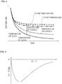
- FIG. 3 shows the relationship of the temperature of glass and the fictive temperature of the glass with time in slowly cooling glass.
- the horizontal axis expresses time
- the vertical axis expresses temperature.
- a solid line expresses the transition of the temperature of glass under certain slow cooling conditions
- a broken line expresses the transition of the fictive temperature of glass at that time.
- a dotted line expresses the transition of the temperature of glass in the case in which the cooling rate is decreased more slowly than under the slow cooling conditions expressed by the solid line
- an alternate long and short dash line expresses the transition of the fictive temperature of glass at that time.
- the fictive temperature of glass is also similarly decreased.
- the rate of the relaxation of the structure of glass forming the optical fiber is very fast.
- the rate of the relaxation of the structure of glass is decreased, and the fictive temperature of glass fails to follow a decrease in the temperature of glass after a while. The temperature difference between the temperature of glass and the fictive temperature of glass is then increased.
- the optical fiber when the cooling rate of glass is slowed, the optical fiber is held in a relatively higher temperature state for a longer time, compared with the case in which the cooling rate is fast.
- the temperature difference between the temperature of glass and the fictive temperature of glass becomes smaller, and the fictive temperature of glass is lower than the example described above. That is, when the cooling rate of glass is slowed, the relaxation of the structure of glass is easily promoted.
- the temperature of the optical fiber in the annealing furnace 121 is preferably 1,600°C or less, and more preferably 1,500°C or less.
- the fictive temperature can be decreased to a lower temperature, but the decrease rate of the fictive temperature is slowed.
- the temperature of the optical fiber in the annealing furnace 121 is preferably 1,300°C or more, and more preferably 1,400°C or more. Therefore, the optical fiber preferably stays in the annealing furnace 121 at least one period during which the temperature of the optical fiber is in a range of temperatures of 1,300°C to 1,500°C, both inclusive. As described above, in the slow cooling process P3, the optical fiber is slowly cooled when the temperature of the optical fiber is in a predetermined range. Thus, the fictive temperature of glass forming the core included in the optical fiber is easily decreased for a shorter time, and transmission losses in the optical fiber are easily reduced.
- the time constant of the relaxation of the structure of glass forming the core included in the optical fiber is defined as ⁇ (T)
- T the temperature of the optical fiber at a certain point in time in the slow cooling process P3
- T f 0 the fictive temperature of glass forming the core at that certain point in time
- T f 0 the fictive temperature of glass forming the core after a lapse of time ⁇ t from the certain point in time
- Equation (6) above shows that the temperature difference (T f - T) between the fictive temperature T f of glass forming the core and the temperature T of the optical fiber depends on the temperature difference (T f 0 - T) between the fictive temperature T f 0 of glass forming the core and the temperature T of the optical fiber at a certain point in time as well as the fictive temperature T f of glass forming the core depends on the time constant ⁇ (T) of the relaxation of the structure.
- the time constant ⁇ (T) of the relaxation of the structure is defined as time until the temperature difference (T f - T) between the fictive temperature T f of glass and the temperature T of glass reaches 1/e when the temperature of glass whose fictive temperature is T f 0 is T.
- a change in the fictive temperature T f per unit time is greater as the temperature difference (T f 0 - T) is greater to some extent.
- FIG. 4 schematically shows the relationship between the temperature difference (T f 0 - T) where the temperature of the optical fiber including the core formed of glass whose fictive temperature is T f 0 is T and a change ((T f - T f 0 )/ ⁇ t) in the fictive temperature T f per unit time.
- the conditions are thought in which the temperature T of the optical fiber is decreased from this point and the temperature difference (T f 0 - T) between the fictive temperature T f 0 of glass forming the core and the temperature T of the optical fiber is increased.
- the time constant ⁇ (T) of the relaxation of the structure of glass forming the core is increased, the change rate of the fictive temperature T f per unit time ((T f - T f 0 )/ ⁇ t) is negatively increased.
- the conditions are thought in which the temperature T of the optical fiber is further decreased and the temperature difference (T f 0 - T) between the fictive temperature T f 0 of glass forming the core and the temperature T of the optical fiber is further increased.
- FIG. 4 shows that as a downward peak expressed in the graph, a change in the fictive temperature per unit time ((T f - T f 0 )/ ⁇ t) takes a minimum value when the temperature difference (T f 0 - T) between the fictive temperature T f 0 of glass forming the core and the temperature T of the optical fiber is a certain value.
- Equation (7) the relationship of Equation (7) below is held between the temperature T of glass and the fictive temperature T f when the decrease rate of the fictive temperature T f of glass is the maximum.
- T 2 + E act / k B ⁇ T ⁇ E act / k B ⁇ T f 0
- the temperature T of glass can be found, at which the fictive temperature T f of glass can be most efficiently decreased.
- the temperature of glass, at which the fictive temperature T f of glass can be most efficiently decreased is sometimes referred to as "the optimized temperature of glass", and the fictive temperature that has been most efficiently decreased is sometimes referred to as "the optimized fictive temperature”.
- T ⁇ E act k B + E act k B 2 + 4 E act k B T f 2
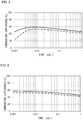
- FIG. 5 These results are shown in FIG. 5 .
- the vertical axis expresses the temperature difference (T f - T) between the fictive temperature T f of glass forming the core and the temperature T of the optical fiber at that fictive temperature T f
- the horizontal axis expresses the slow cooling time of the optical fiber.
- a solid line expresses the result using the constant A and the activation energy E act described in Non-Patent Literature 1
- a broken line expresses the result using the constant A and the activation energy E act described in Non-Patent Literature 2.
- the fictive temperature of glass forming the core where slow cooling time is 0.5 second is found as temperatures of 1,390°C and 1,322°C.
- the temperature difference (T f - T) has to be less than about 60°C
- the temperature T of the optical fiber is controlled so that in almost all the time domains, the temperature difference (T f - T) is kept higher than about 40°C and less than about 60°C, and hence the fictive temperature T f of glass forming the core is efficiently decreased.
- Equation 5 is the maximum, is about 0.01 second, although the time is varied more or less depending on the constant A and the activation energy E act in Equation (5) above, and the temperature T 0 of the optical fiber and the fictive temperature T f 0 of glass forming the core at the beginning of slow cooling, at which slow cooling time is zero second.
- the temperature conditions are the conditions shown on the left side of the minimum value of a change in the fictive temperature per unit time ((T f - T f 0 )/ ⁇ t) shown in the graph in FIG. 4 .
- precooling process P2 is provided before the slow cooling process P3, precooling is performed so that the temperature difference (T f - T) is about 60°C in the precooling process P2, and then the slow cooling process P3 is performed.
- FIG. 6 shows a variation over time of the temperature difference (T f - T) between the value where the fictive temperature T f of glass forming the core takes the lowest value and the temperature T of the optical fiber at that value.
- T f - T the temperature difference
- the vertical axis expresses the temperature difference (T f - T) between the value where the fictive temperature T f of glass forming the core takes the lowest value and the temperature T of the optical fiber at that value, and the horizontal axis expresses the slow cooling time of the optical fiber.
- a solid line expresses the result using the constant A and the activation energy E act described in Non-Patent Literature 1
- a broken line expresses the result using the constant A and the activation energy E act described in Non-Patent Literature 2. As illustrated in FIG.
- the temperature difference (T f - T) is monotonously decreased in all the time domains and the temperature T of the optical fiber is maintained in a range suitable for a decrease in the fictive temperature T f of glass forming the core.
- the fictive temperature of glass forming the core where slow cooling time is 0.5 second is derived as temperatures of 1,387°C and 1,321°C, and the fictive temperature of glass forming the core can be decreased more than the fictive temperature under the conditions shown in FIG. 5 .
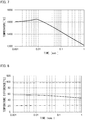
- the temperature conditions are the conditions shown on the right side of the minimum value of a change in the fictive temperature per unit time ((T f - T f 0 )/ ⁇ t) shown in the graph in FIG. 4 . That is, in the case in which the fictive temperature T f of glass forming the core is higher with respect to the temperature T of the optical fiber, the temperature T of the optical fiber is increased and brought close to the fictive temperature T f to decrease the temperature difference (T f - T), which accelerates the relaxation of the structure. Thus, FIG. 7 shows that the temperature T of the optical fiber is temporarily increased from the beginning of slow cooling up to about 0.01 second.
- the temperature T of the optical fiber is monotonously decreased similarly in FIG. 6 .
- the fictive temperature of glass forming the core where slow cooling time is 0.5 second is derived as 1,389°C.
- the fictive temperature of glass forming the core can be decreased more than under the conditions shown in FIG. 5 , the fictive temperature is inferior to that under the conditions shown in FIG. 6 .
- the precooling process P2 is provided subsequent to the drawing process P1 so that the temperature difference (T f - T) between the fictive temperature of glass forming the core and the temperature of the optical fiber is reached at an appropriate level and then the slow cooling process P3 is performed, which allows the efficient relaxation of the structure of glass forming the core with the advantageous use of the duration of the optical fiber in the annealing furnace. That is, the precooling process P2 is performed until the temperature difference (T f - T) between the fictive temperature of glass forming the core and the temperature of the optical fiber is reached at about 60°C, and then the slow cooling process P3 is started, which allows the advantageous use of the duration of the optical fiber in the annealing furnace.
- the plurality of the annealing furnaces 121 is used in a period from the start to the end of the slow cooling process P3, and the optical fiber is in turn delivered into the annealing furnaces 121 with the temperature T being gradually decreased. From the results shown in FIGS. 5 and 6 , the temperature difference (T f - T) between the temperature of the optical fiber and the fictive temperature of glass forming the core included in the optical fiber when the relaxation of the structure is efficiently caused by slow cooling is monotonously decreased with a lapse of slow cooling time.
- T the time constant of the relaxation of the structure of glass forming the core
- T f the temperature of the optical fiber at a certain point in time in the slow cooling process P3
- T f 0 the fictive temperature of glass forming the core at the certain point in time
- T f the fictive temperature of glass forming the core after a lapse of time ⁇ t from the certain point in time
- the temperature of the optical fiber at a point in time when the optical fiber is delivered into the nth annealing furnace 121 from the upstream side is defined as T n
- the fictive temperature of glass forming the core at the point in time when the optical fiber is delivered into the annealing furnace is defined as T fn
- the fictive temperature of glass forming the core after a lapse of time ⁇ t from the point in time when the optical fiber is delivered into the annealing furnace is defined as T f
- Equation (2) below is preferably held.
- the preset temperatures of the annealing furnaces 121 are appropriately controlled, and hence the temperature difference (T f - T) between the temperature T of the optical fiber when delivered into each of the annealing furnaces 121 and the fictive temperature T f of glass forming the core included in the optical fiber is controlled in the predetermined range, and the relaxation of the structure of glass forming the core included in the optical fiber is more easily promoted.
- transmission losses in the optical fiber are easily reduced.
- the conditions for the temperature difference (T f - T) between the temperature T of the optical fiber and the fictive temperature T f of glass forming the core included in the optical fiber in order to most efficiently decrease the fictive temperature T f of glass forming the core are as described above.
- transmission losses in the optical fiber can also be sufficiently reduced under the conditions described below.
- the fictive temperature T f of glass forming the core included in the optical fiber can be tied to transmission losses in the optical fiber by a relational expression below.
- a Rayleigh scattering coefficient R r is proportional to the fictive temperature T f of glass forming the core, and a transmission loss ⁇ T caused by Rayleigh scattering is expressed by Equation (9) below where the wavelength of light to be transmitted is ⁇ ( ⁇ m).
- B 4.0 ⁇ 10 -4 dB/km/ ⁇ m 4 /K.
- a transmission loss at the wavelength ⁇ 1.55 ⁇ m.
- the Rayleigh transmission loss ⁇ T caused by Rayleigh scattering is increased by about 0.001 dB/km. That is, when errors from the optimized fictive temperature T f can be restricted less than 14°C, an increase in the Rayleigh transmission loss ⁇ caused by Rayleigh scattering can be controlled to less than 0.001 dB/km.
- the optical fiber only has to be delivered into the annealing furnace 121 under the temperature conditions in which the temperature difference (T f - T) between the fictive temperature T f of glass forming the core and the temperature of the optical fiber is higher than about 20°C and lower than about 100°C as described below.
- T f - T the fictive temperature T f 0 of glass forming the core of the optical fiber at the beginning of slow cooling, at which slow cooling time is zero second, is 1,560°C, and the temperature difference (T f - T) is almost constant during the slow cooling process P3.
- Recurrence formula (6) is solved using the values described in Non-Patent Literature 1 above for the constant A and the activation energy E act , and then a graph shown in FIG. 8 is obtained.
- a broken line expresses the upper limit of the variation over time of the temperature difference (T f - T) in the case in which the amount of an increase in a transmission loss expressed from the fictive temperature T f of glass forming the core when the optical fiber is slowly cooled for 0.5 second at the temperature difference (T f - T) expressed by the solid line in FIG. 6 is 0.001 dB/km or less, and an alternate long and short dash line expresses the lower limit.
- the temperature difference (T f - T) expressed by the solid line in FIG. 6 is again expressed by a solid line.
- the result shown in FIG. 8 reveals the following.
- the temperature of the annealing furnace 121 only has to be set so as to control the temperature history of the optical fiber in which the temperature difference (T f - T) is in a range of above about 20°C and less than about 100°C during the slow cooling process P3
- an increase in the fictive temperature of glass forming the core is restricted up to a rise of about 14°C with respect to the optimized fictive temperature T f .
- an increase can be restricted to an increase of 0.001 dB/km or less with respect to the values under the optimized conditions under which transmission losses are most decreased.
- the temperature of the optical fiber at a point in time when the optical fiber is delivered into the nth annealing furnace from the upstream side is defined as T n
- the fictive temperature of glass forming the core at the point in time when the optical fiber is delivered into the annealing furnace is defined as T fn
- the fictive temperature of glass forming the core after a lapse of time ⁇ t from the point in time when the optical fiber is delivered into the annealing furnace is defined as T f
- Equation (1) below is preferably held.
- the optical fiber only has to be delivered into the annealing furnace 121 under the temperature conditions in which the temperature difference (T f - T) between the fictive temperature T f of glass forming the core and the temperature of the optical fiber is higher than about 20°C and lower than about 100°C.
- Equation (2) or (1) above a specific example for easily satisfying the conditions of Equation (2) or (1) above will be described.
- four annealing furnaces 121a, 121b, 121c, and 121d are used in the slow cooling process P3.
- the plurality of the annealing furnaces 121 is used in this manner, and hence the temperature difference between the temperature of the optical fiber and the fictive temperature of glass forming the core is easily controlled in a predetermined range. That is, in the slow cooling process P3, when the optical fiber is passed through the plurality of the annealing furnaces 121 and the preset temperature of the nth annealing furnace 121 from the upstream side is defined as T sn , the relationship of Equation (3) below is to be held. 20 ° C ⁇ T fn ⁇ T sn ⁇ 100 ° C
- the optical fiber is slowly cooled with the temperature difference (T f - T) between the temperature of the optical fiber and the fictive temperature of glass forming the core included in the optical fiber being controlled in a predetermined range, and hence the relaxation of the structure of glass forming the core is promoted.
- T f - T temperature difference between the temperature of the optical fiber and the fictive temperature of glass forming the core included in the optical fiber
- the plurality of the annealing furnaces 121 is used, and the preset temperatures of the annealing furnaces 121 is controlled in a predetermined range with respect to the fictive temperature of glass forming the core in slow cooling time until which the optical fiber is reached at the inlet port of each of the annealing furnaces 121, and hence the temperature difference between the temperature of the optical fiber and the fictive temperature of glass forming the core included in the optical fiber is easily controlled in a predetermined range. As a result, the relaxation of the structure of glass forming the core is promoted, and transmission losses in the optical fiber are reduced. Referring to FIG. 9 , this will be described more in detail below.
- FIG. 9 shows a change in the optimized fictive temperature of glass forming the core (a solid line) calculated from Equation (5) when assuming initial values where the temperature T 0 of the optical fiber is 1,500°C and the fictive temperature T f 0 of glass forming the core at this time is 1,560°C, the preset temperatures of the annealing furnaces 121a, 121b, 121c, and 121d (an alternate long and short dash line), and the expected fictive temperature of glass forming the core in slow cooling time until which the optical fiber is reached at the inlet ports or the outlet ports of the annealing furnaces 121a, 121b, 121c, and 121d.
- the lengths of the annealing furnaces 121 are each 0.5 m and the drawing rate is 20 m/second.
- the optimized fictive temperature T f is calculated as temperatures of 1,560°C, 1,517°C, 1,493°C, 1,477°C, and 1,464°C, respectively.
- the preset temperatures of the annealing furnaces 121a, 121b, 121c, and 121d are then set as expressed by the alternate long and short dash line in FIG.
- the temperatures of the annealing furnaces 121 are set to a temperature lower than the optimized fictive temperature T f of glass forming the core at the slow cooling time at which the optical fiber is reached at the inlet port of each of the annealing furnaces 121 by 70°C.
- T f - T the temperature difference between the fictive temperature of glass and the temperature of the optical fiber at that fictive temperature
- the actual fictive temperature of glass is more gently decreased and close to the preset temperature of the annealing furnace, the actual fictive temperature is slightly higher than optimized fictive temperatures expressed by the solid triangles and slightly lower than the fictive temperatures expressed by the solid circles. However, this is errors in a tolerable range.
- the temperature difference between the fictive temperature of glass through a fictive temperature history after slow cooling for 0.100 second and the optimized fictive temperature is 1.1°C, which the different in the scattering loss is only less than 0.001 dB/km.
- Equation (4) is preferably held. 40 ° C ⁇ T fn ⁇ T sn ⁇ 60 ° C
- the preset temperature of the annealing furnace 121 is controlled in a more appropriate range, and hence the effect of promoting the relaxation of the structure of glass forming the core included in the optical fiber is easily increased, and transmission losses in the optical fiber are easily reduced.
- the temperature difference between the preset temperature and the fictive temperature of glass forming the core at the inlet port is preferably smaller in the annealing furnace 121 provided on the downstream side than in the annealing furnace 121 provided on the upstream side. For example, as expressed by the solid line in FIG.
- the temperature difference between the optimized temperature of glass and the optimized fictive temperature of glass forming the core at slow cooling time of 0.025 second, 0.050 second, 0.075 second, and 0.100 second is temperatures of 55°C, 54°C, 53°C, and 52°C, respectively.
- the temperature difference is preferably smaller toward the downstream side.
- the temperature of the annealing furnace is set so that the temperature difference between the preset temperature and the fictive temperature of glass forming the core at the inlet port is smaller in the annealing furnace provided on the downstream side than in the annealing furnace provided on the upstream side.
- the relaxation of the structure of glass forming the core can be efficiently promoted. As a result, transmission losses in the optical fiber are more easily reduced.
- the relationship between the temperature T of the optical fiber and the fictive temperature T f of glass forming the core depends solely on the slow cooling time t when the composition of the optical fiber is the same, and the slow cooling time t, the length L of the annealing furnace, and the drawing rate v can be correlated with one another based on the relationship of Equation (10) below.
- t L / v
- the slow cooling time t needs about 0.1 second to set the fictive temperature T f to 1,500°C.
- the length L of the annealing furnace needs two meters.
- the slow cooling time t needs about 0.4 second in order to set the fictive temperature T f to 1,400°C, for example.
- the drawing rate v is set to 10 m/second
- the length L of the annealing furnace needs four meters.
- the length L of the annealing furnace has only two meters, it is revealed that it is necessary to set the drawing rate v to 5 m/second.
- the drawing rate v is preferably selected in a range of about 10 to 50 m/second
- the length L of the annealing furnace is preferably selected in a range of about one to ten meters
- the slow cooling time t is preferably one second or less.
- the optical fiber is covered with a coating layer to enhance the resistance against external flaws, for example.
- this coating layer is formed of an ultraviolet curable resin.
- the temperature of the optical fiber affects the viscosity of a resin to be applied, and as a result, this affects the thickness of the coating layer.
- a suitable temperature of the optical fiber in forming the coating layer is appropriately determined suitable for the properties of a resin forming the coating layer.
- the optical fiber production method according to the embodiment since the annealing furnace 121 is provided between the drawing furnace 110 and a coater 131, the section for sufficiently cooling the optical fiber is decreased. More specifically, the optical fiber production method according to the embodiment also includes the precooling process P2, further decreasing the section sufficiently cooling the optical fiber.
- the optical fiber production method according to the embodiment includes the rapid cooling process P4 in which the optical fiber delivered out of the annealing furnace 121 is rapidly cooled using a cooling device 122. In the rapid cooling process P4, the optical fiber is rapidly cooled faster than in the slow cooling process P3. Since the rapid cooling process P4 performed in this manner is provided the temperature of the optical fiber can be sufficiently decreased in a shorter section, easily forming the coating layer.
- the temperature of the optical fiber when it is delivered out of the cooling device 122 is in a range of temperatures of 40°C to 50°C, for example.
- the optical fiber which has been passed through the cooling device 122 and cooled to a predetermined temperature, is passed through a coater 131 containing an ultraviolet curable resin to be the coating layer that covers the optical fiber, and the optical fiber is covered with this ultraviolet curable resin.
- the optical fiber is further passed through an ultraviolet irradiator 132, ultraviolet rays are applied to the optical fiber, the coating layer is formed, and then the optical fiber 1 is formed.
- the coating layer is typically formed of two layers. In the case of forming a two-layer coating layer, after the optical fiber is covered with ultraviolet curable resins forming the respective layers, the ultraviolet curable resins are cured at one time, and then the two-layer coating layer can be formed. Alternatively, after forming a first coating layer, a second coating layer may be formed. The direction of the optical fiber 1 is changed by a turn pulley 141, and then the optical fiber 1 is wound on a reel 142.
- the present invention is described with the preferred embodiment taken as an example.
- the present invention is not limited to this embodiment. That is, the optical fiber production method according to the present invention only has to include the drawing process and the slow cooling process described above. The precooling process and the rapid cooling process are not essential processes.
- the optical fiber production method according to the present invention is applicable to the manufacture of any types of optical fibers.
- the optical fiber production method according to the present invention is applicable also to production methods for optical fibers having different materials, such as chalcogenide glass and fluorine glass, as a principal component, as well as production methods for optical fibers having silica glass as a principal component, if the constant A and the activation energy E act in Equation (5) above are derived.
- an optical fiber production method with which an optical fiber with decreased transmission losses can be manufactured, and the method can be used in the field of optical fiber communications.
- the method can also be used for optical fiber production methods for use in fiber laser devices and other devices using optical fibers.
Landscapes
- Engineering & Computer Science (AREA)
- Chemical & Material Sciences (AREA)
- Physics & Mathematics (AREA)
- Manufacturing & Machinery (AREA)
- General Life Sciences & Earth Sciences (AREA)
- Geochemistry & Mineralogy (AREA)
- Life Sciences & Earth Sciences (AREA)
- Materials Engineering (AREA)
- Organic Chemistry (AREA)
- Thermal Sciences (AREA)
- General Physics & Mathematics (AREA)
- Optics & Photonics (AREA)
- Manufacture, Treatment Of Glass Fibers (AREA)
Abstract
Description
- The present invention relates to an optical fiber production method.
- In optical fiber communication systems, in order to increase the reach and the rate of optical transmission, the optical signal-to-noise ratio has to be increased. Thus, a decrease in transmission losses in optical fibers is demanded. Nowadays, since an optical fiber production method is highly sophisticated, transmission losses caused by impurities contained in optical fibers are closed to the lower limits. A remaining main cause of transmission losses is scattering losses in association with fluctuations in the structure or composition of glass forming optical fibers. This is inevitable, because optical fibers are formed of glass.
- As a method of decreasing fluctuations in the structure of glass, a method is known to cool molten glass slowly. As a method of slowly cooling molten glass, an attempt is made to slowly cool an optical fiber drawn from a drawing furnace immediately. Specifically, it is investigated to decrease the cooling rate of the optical fiber that an optical fiber drawn from a drawing furnace is heated in an annealing furnace, or an optical fiber drawn from a drawing furnace is surrounded by a heat insulator immediately.
-
Patent Literature 1 below discloses a method of setting the temperature of a heating furnace (an annealing furnace) is ±100°C or less of the target temperature found by a recurrence formula in 70% or more of a region from a position at which the outer diameter of a silica based optical fiber having a core and a cladding becomes smaller than 500% of the final outer diameter to a position at which the temperature of the optical fiber is 1,400°C. Since the temperature history of the optical fiber is controlled in this manner, the fictive temperature of glass forming the optical fiber is decreased to reduce transmission losses. - [Patent Literature 1]
JP2014-62021A - However, the technique disclosed in
Patent Literature 1 above is required to repeat complex calculations in order to adjust the temperature of the optical fiber to an ideal temperature change found by the recurrence formula. The technique disclosed inPatent Literature 1 permits the temperature of the optical fiber to have a temperature shift of as large as ±50°C to 100°C with respect to the target temperature found by the recurrence formula. When the temperature shift of the optical fiber is permitted in such a large deviation, it is difficult to say that the temperature history is sufficiently optimized. For example, supposing that the temperature of the optical fiber slowly cooled is changed in a range of ±100°C, the fictive temperature of glass forming the optical fiber is also changed in a similar range, and only an optical fiber having a fictive temperature that is 100°C higher than a fictive temperature reachable based on a target temperature found by the recurrence formula, transmission losses of the obtained optical fiber caused by light scattering are increased as large as by 0.007 dB/km. In such the disclosed production methods in which the temperature history of the optical fiber is not sufficiently optimized, capital investment is excessively spent for elongating the annealing furnace more than necessary, or productivity is degraded by decreasing the drawing rate more than necessary. - The present inventor found that the transmission losses in the optical fiber caused by light scattering are reduced easily by appropriately setting the temperature of the annealing furnace and appropriately controlling the temperature difference between the fictive temperature of glass forming the optical fiber and the temperature of the optical fiber, because of promoting the relaxation of the structure of glass forming the optical fiber.
- Therefore, the present invention is to provide an optical fiber production method that easily reduces transmission losses in the optical fiber.
- To solve the problem, an optical fiber production method according to the present invention includes: a drawing process of drawing an optical fiber from an optical fiber preform in a drawing furnace; and a slow cooling process of slowly cooling the optical fiber drawn in the drawing process. In the slow cooling process, the optical fiber is passed through a plurality of annealing furnaces. Equation (1) below is held in a given period in the slow cooling process, where a time constant of relaxation of a structure of glass forming a core included in the optical fiber is defined as τ(Tn), a temperature of the optical fiber at a point in time when the optical fiber is delivered into an nth annealing furnace from an upstream side in the slow cooling process is defined as Tn, a fictive temperature of glass forming the core at the point in time when the optical fiber is delivered is defined as Tfn, and a fictive temperature of glass forming the core after a lapse of time Δt from the point in time when the optical fiber is delivered is defined as Tf.

- The present inventors found that the optical fiber is slowly cooled with the temperature difference between the temperature of the optical fiber and the fictive temperature of glass forming the core included in the optical fiber being controlled in the predetermined range and hence the relaxation of the structure of glass forming the core is promoted. With the promotion of the relaxation of the structure of glass forming the core, scattering losses caused by fluctuations in the structure of glass forming the core in the transmission of light through the core are reduced, and hence transmission losses in the optical fiber are reduced. As described above, the plurality of annealing furnaces is used in the slow cooling process, the preset temperatures of the annealing furnaces are appropriately controlled, and hence the temperature difference between the temperature of the optical fiber and the fictive temperature of glass forming the core included in the optical fiber is easily controlled in the predetermined range. As a result, the relaxation of the structure of glass forming the core is promoted, and transmission losses in the optical fiber are easily reduced.
- In the optical fiber production method according to the present invention, Equation (2) below is preferably held in a given period in the slow cooling process.

- In this manner, in the slow cooling process, the temperature difference (Tf - Tn) between the temperature Tn of the optical fiber and the fictive temperature Tf of glass forming the core included in the optical fiber is controlled in a more suitable range, and hence the relaxation of the structure of glass forming the core included in the optical fiber is more easily promoted, and transmission losses in the optical fiber are more easily reduced.
- In the optical fiber production method according to the present invention, a relationship of Equation (3) below is preferably held, where a preset temperature of the nth annealing furnace is defined as Tsn.

- As described above, the plurality of annealing furnaces is used in the slow cooling process, the preset temperatures of the annealing furnaces are controlled in a predetermined range with respect to the fictive temperature of glass forming the core at the inlet ports of the annealing furnaces, and hence the temperature difference between the temperature of the optical fiber and the fictive temperature of glass forming the core included in the optical fiber is easily controlled in a predetermined range. As a result, the relaxation of the structure of glass forming the core is promoted, and transmission losses in the optical fiber are easily reduced.
- In the optical fiber production method according to the present invention, Equation (4) below is preferably held.

- In this manner, the preset temperatures of the plurality of the annealing furnaces are individually controlled in a more suitable range, and hence the effect of promoting the relaxation of the structure of glass forming the core included in the optical fiber is easily increased, and transmission losses in the optical fiber are more easily reduced.
- In the optical fiber production method according to the present invention, a temperature difference between a preset temperature and a fictive temperature of glass forming the core at an inlet port is preferably smaller in the annealing furnace provided on a downstream side than in the annealing furnace provided on an upstream side.
- The present inventors found that when the temperature of glass becomes low, a small temperature difference between the fictive temperature of glass and the temperature of glass easily promotes the relaxation of the structure of glass. Thus, the temperature of the annealing furnace is set so that the temperature difference between the preset temperature and the fictive temperature of glass forming the core at the inlet port is smaller in the annealing furnace provided on the downstream side than in the annealing furnace provided on the upstream side. Thus, the relaxation of the structure of glass forming the core can be efficiently promoted. As a result, transmission losses in the optical fiber are more easily reduced.
- Preferably, the optical fiber is in any one of the plurality of annealing furnaces during at least certain period for which a temperature of the optical fiber is in a range of 1,300°C or more and 1,500°C or less.
- The optical fiber is slowly cooled when the temperature of the optical fiber is in this range, and hence the fictive temperature of glass forming the core included in the optical fiber is easily decreased for a shorter time, and transmission losses in the optical fiber are easily reduced.
- As described above, according to the present invention, an optical fiber production method that easily reduces transmission losses in the optical fiber is provided.
-
-
FIG. 1 is a flowchart of the processes of an optical fiber production method according to the present invention. -
FIG. 2 is a schematic diagram of the configuration of devices for use in an optical fiber production method according to the present invention. -
FIG. 3 is a graph of the relationship of the temperature of glass and the fictive temperature of the glass with slow cooling time. -
FIG. 4 is a graph schematically showing the relationship of the temperature difference (Tf 0 - T) between the fictive temperature of glass and the temperature of glass with the decrease rate ((Tf - Tf 0)/Δt) of the fictive temperature of glass per unit time. -
FIG. 5 is a graph of a temporal change in the temperature difference between the fictive temperature of glass and the temperature of glass. -
FIG. 6 is a graph of a temporal change in the temperature difference between the fictive temperature of glass and the temperature of glass under the initial conditions different from those inFIG. 5 . -
FIG. 7 is a graph of a temporal change in the temperature of glass under the initial conditions different from those inFIGS. 5 and 6 . -
FIG. 8 is a graph of the upper limit and the lower limit of the variation over time in the optimized temperature difference (Tf - T) depicted by a solid line inFIG. 6 and the temperature difference (Tf - T) in which a transmission loss caused by scattering is not increased by 0.001 dB/km or more. -
FIG. 9 is a graph of the preset temperatures of annealing furnaces, the optimized fictive temperature of glass at the inlet ports of the annealing furnaces, and the fictive temperature of glass through the fictive temperature history at the inlet ports of the annealing furnaces. - In the following, a preferred embodiment of an optical fiber production method according to the present invention will be described in detail with reference to the drawings.
-
FIG. 1 is a flowchart of the processes of an embodiment of an optical fiber production method according to the present invention. As illustrated inFIG. 1 , the optical fiber production method according to the embodiment includes a drawing process P1, a precooling process P2, a slow cooling process P3, and a rapid cooling process P4. In the following, these processes will be described. Note that,FIG. 2 is a schematic diagram of the configuration of devices for use in the optical fiber production method according to the embodiment. - The drawing process P1 is a process in which one end of an
optical fiber preform 1P is drawn in adrawing furnace 110. First, theoptical fiber preform 1P is prepared. Theoptical fiber preform 1P is formed of glass having refractive index profiles the same as the refractive index profiles of a core and a cladding forming a desiredoptical fiber 1. Theoptical fiber 1 includes one or a plurality of cores and a cladding surrounding the outer circumferential surface of the core with no gap. The core and the cladding are formed of silica glass. The refractive index of the core is higher than the refractive index of the cladding. For example, in the case in which the core is formed of silica glass doped with a dopant, such as germanium, which increases the refractive index, the cladding is formed of pure silica glass. For example, in the case in which the core is formed of pure silica glass, the cladding is formed of silica glass doped with a dopant, such as fluorine, which decreases the refractive index. - Subsequently, the
optical fiber preform 1P is suspended so that the longitudinal direction is perpendicular. Theoptical fiber preform 1P is disposed in thedrawing furnace 110, aheating unit 111 is caused to generate heat, and then the lower end portion of theoptical fiber preform 1P is heated. At this time, the lower end portion of theoptical fiber preform 1P is heated at a temperature of 2,000°C, for example, to be molten. From the heated lower end portion of theoptical fiber preform 1P, molten glass is drawn out of thedrawing furnace 110 at a predetermined drawing rate. - The precooling process P2 is a process in which the optical fiber drawn out of the
drawing furnace 110 in the drawing process P1 is cooled to a predetermined temperature suitable for delivering the optical fiber into anannealing furnace 121, described later. A predetermined temperature of the optical fiber suitable for delivering the optical fiber into theannealing furnace 121 will be described later in detail. - In the optical fiber production method according to the embodiment, the precooling process P2 is performed by passing the optical fiber drawn in the drawing process P1 through the hollow portion of a
tubular body 120 provided directly below the drawingfurnace 110. Thetubular body 120 is provided directly below the drawingfurnace 110, causing the atmosphere in the inside of the hollow portion of thetubular body 120 to be almost the same as the atmosphere in the inside of thedrawing furnace 110. Thus, a sudden change in the atmosphere and the temperature around the optical fiber immediately after drawn is reduced. - The temperature of the optical fiber to be delivered into the
annealing furnace 121 is mainly determined by the drawing rate and the atmosphere in thedrawing furnace 110. The precooling process P2 is provided, which further finely adjusts the cooling rate of the optical fiber for easy adjustment of the incoming temperature of the optical fiber to be delivered into theannealing furnace 121 to a suitable range. Based on the temperatures of the optical fiber drawn out of thedrawing furnace 110 and suitable for delivering the optical fiber into theannealing furnace 121, the distance from theannealing furnace 121 to thedrawing furnace 110 and the length of thetubular body 120 can be appropriately selected. Thetubular body 120 is formed of a metal tube, for example. The cooling rate of the optical fiber may be adjusted by air-cooling the metal tube or by providing a heat insulator around the metal tube. - The slow cooling process P3 is a process in which the optical fiber, which is drawn out in the drawing process P1, is slowly cooled. In the optical fiber production method according to the embodiment, the temperature of the optical fiber is adjusted through the precooling process P2, and then the optical fiber is slowly cooled in the slow cooling process P3. In the slow cooling process P3, the optical fiber is passed through a plurality of
annealing furnaces annealing furnace 121". Note that, inFIG. 2 , fourannealing furnaces - The temperature in the inside of the
annealing furnace 121 is a predetermined temperature different from the temperature of the optical fiber to be delivered into theannealing furnace 121. The cooling rate of the optical fiber is decreased by the temperature around the optical fiber delivered into theannealing furnace 121. The cooling rate of the optical fiber is decreased in theannealing furnace 121. Thus, the structure of glass forming the core included in the optical fiber is relaxed, and theoptical fiber 1 with decreased scattering losses is obtained, as described below. - In the disclosed optical fiber production methods having the slow cooling process, the temperature of the optical fiber is not sufficiently optimized when the optical fiber is delivered into the annealing furnace. Specifically, the optical fiber is sometimes delivered into the annealing furnace with the temperature of the optical fiber being too high or too low. When the temperature of the optical fiber to be delivered into the annealing furnace is too high, the rate to relax the structure of glass forming the optical fiber is too fast, hardly expecting the effect of slowly cooling the optical fiber. On the other hand, when the temperature of the optical fiber to be delivered into the annealing furnace is too low, the rate to relax the structure of glass forming the optical fiber is decreased, sometimes causing a necessity to heat up again the optical fiber in the annealing furnace, for example. As described above, in the disclosed slow cooling processes, it is difficult to say that the relaxation of the structure of glass forming the optical fiber is efficiently performed. Thus, the annealing furnace is elongated more than necessary, which might demand an excessive capital investment, or the drawing rate is decreased more than necessary, which might degrade productivity.
- According to the optical fiber production method of the embodiment, in the slow cooling process P3, the temperature of the
annealing furnace 121 is appropriately set, the temperature difference between the fictive temperature of glass forming the core included in the optical fiber and the temperature of the optical fiber is appropriately controlled, and hence the relaxation of the structure of glass forming the core is promoted. As a result, theoptical fiber 1 having decreased transmission losses can be obtained with no requirement of excessive capital investment and with excellent productivity. According to the optical fiber production method of the embodiment, complex calculation is unnecessary unlike the technique disclosed inPatent Literature 1 described above. - In silica glass classified as so-called strong glass, the time constant τ(T) of the structural relaxation, which is thought to correspond to the viscosity flow of glass, follows the Arrhenius equation. Thus, the time constant τ(T) is expressed as Equation (5) as a function of the temperature T of glass using a constant A and an activation energy Eact determined by the composition of glass. Note that, kB is Boltzmann constant.

- Equation (5) above shows that the structure of glass is relaxed faster as the temperature of glass is higher and reached faster in the equilibrium state at the given temperature. That is, the fictive temperature of glass more quickly comes close to the temperature of glass faster as the temperature of glass is higher.
-
FIG. 3 shows the relationship of the temperature of glass and the fictive temperature of the glass with time in slowly cooling glass. In the graph ofFIG. 3 , the horizontal axis expresses time, and the vertical axis expresses temperature. InFIG. 3 , a solid line expresses the transition of the temperature of glass under certain slow cooling conditions, and a broken line expresses the transition of the fictive temperature of glass at that time. A dotted line expresses the transition of the temperature of glass in the case in which the cooling rate is decreased more slowly than under the slow cooling conditions expressed by the solid line, and an alternate long and short dash line expresses the transition of the fictive temperature of glass at that time. - As expressed by the solid line and the broken line in
FIG. 3 , when the temperature of glass is decreased over a lapse of time in the high temperature area, the fictive temperature of glass is also similarly decreased. As described above, in the state in which the temperature of glass is sufficiently high, the rate of the relaxation of the structure of glass forming the optical fiber is very fast. However, as the temperature of glass is decreased, the rate of the relaxation of the structure of glass is decreased, and the fictive temperature of glass fails to follow a decrease in the temperature of glass after a while. The temperature difference between the temperature of glass and the fictive temperature of glass is then increased. Here, when the cooling rate of glass is slowed, the optical fiber is held in a relatively higher temperature state for a longer time, compared with the case in which the cooling rate is fast. Thus, as expressed by the dotted line and the alternate long and short dash line inFIG. 3 , the temperature difference between the temperature of glass and the fictive temperature of glass becomes smaller, and the fictive temperature of glass is lower than the example described above. That is, when the cooling rate of glass is slowed, the relaxation of the structure of glass is easily promoted. - As described above, when the temperature of glass is high, the structure of glass is relaxed fast. However, the fictive temperature of glass does not reach to the below of the temperature of glass. Thus, when the temperature of glass is high, the fictive temperature of the glass also remains high. That is, when the temperature of glass is too high, the effects obtained by slow cooling are poor. From this viewpoint, the temperature of the optical fiber in the
annealing furnace 121 is preferably 1,600°C or less, and more preferably 1,500°C or less. On the other hand, in the case in which the temperature of glass is low, the fictive temperature can be decreased to a lower temperature, but the decrease rate of the fictive temperature is slowed. That is, when the temperature of glass is too low, it will take longer time for slow cooling in order to sufficiently decrease the fictive temperature. From this viewpoint, the temperature of the optical fiber in theannealing furnace 121 is preferably 1,300°C or more, and more preferably 1,400°C or more. Therefore, the optical fiber preferably stays in theannealing furnace 121 at least one period during which the temperature of the optical fiber is in a range of temperatures of 1,300°C to 1,500°C, both inclusive. As described above, in the slow cooling process P3, the optical fiber is slowly cooled when the temperature of the optical fiber is in a predetermined range. Thus, the fictive temperature of glass forming the core included in the optical fiber is easily decreased for a shorter time, and transmission losses in the optical fiber are easily reduced. - Next, the following is the description in which the relaxation of the structure of glass forming the core is efficiently promoted to reduce transmission losses in the optical fiber by what manner of slowly cooling the optical fiber by means of the relationship between the temperature of glass and the fictive temperature of glass.
- Under the conditions in which the time constant of the relaxation of the structure of glass forming the core included in the optical fiber is defined as τ(T), the temperature of the optical fiber at a certain point in time in the slow cooling process P3 is defined as T, and the fictive temperature of glass forming the core at that certain point in time is defined as Tf 0, the fictive temperature Tf of glass forming the core after a lapse of time Δt from the certain point in time is expressed as Equation (6) below based on Equation (5) above. Note that, Δt is a short period of time, and the temperature of the optical fiber T for this period is supposed to be constant.

- Equation (6) above shows that the temperature difference (Tf - T) between the fictive temperature Tf of glass forming the core and the temperature T of the optical fiber depends on the temperature difference (Tf 0 - T) between the fictive temperature Tf 0 of glass forming the core and the temperature T of the optical fiber at a certain point in time as well as the fictive temperature Tf of glass forming the core depends on the time constant τ(T) of the relaxation of the structure. The time constant τ(T) of the relaxation of the structure is defined as time until the temperature difference (Tf - T) between the fictive temperature Tf of glass and the temperature T of glass reaches 1/e when the temperature of glass whose fictive temperature is Tf 0 is T.
A change in the fictive temperature Tf per unit time is greater as the temperature difference (Tf 0 - T) is greater to some extent. -
FIG. 4 schematically shows the relationship between the temperature difference (Tf 0 - T) where the temperature of the optical fiber including the core formed of glass whose fictive temperature is Tf 0 is T and a change ((Tf - Tf 0)/Δt) in the fictive temperature Tf per unit time. As shown inFIG. 4 , under the conditions in which the fictive temperature Tf 0 of glass forming the core coincides with the temperature T of the optical fiber (Tf 0 = T), the relaxation of the structure of glass forming the core does not occur, and a change in the fictive temperature per unit time is zero ((Tf - Tf 0)/Δt = 0). The conditions are thought in which the temperature T of the optical fiber is decreased from this point and the temperature difference (Tf 0 - T) between the fictive temperature Tf 0 of glass forming the core and the temperature T of the optical fiber is increased. Under the conditions, although the time constant τ(T) of the relaxation of the structure of glass forming the core is increased, the change rate of the fictive temperature Tf per unit time ((Tf - Tf 0)/Δt) is negatively increased. However, the conditions are thought in which the temperature T of the optical fiber is further decreased and the temperature difference (Tf 0 - T) between the fictive temperature Tf 0 of glass forming the core and the temperature T of the optical fiber is further increased. Under the conditions, the time constant τ(T) of the relaxation of the structure of glass forming the core is now increased, and the absolute value of a change in the fictive temperature Tf per unit time ((Tf - Tf 0)/Δt) is decreased. That is,FIG. 4 shows that as a downward peak expressed in the graph, a change in the fictive temperature per unit time ((Tf - Tf 0)/Δt) takes a minimum value when the temperature difference (Tf 0 - T) between the fictive temperature Tf 0 of glass forming the core and the temperature T of the optical fiber is a certain value. - Here, solving Equation (6) above shows that the relationship of Equation (7) below is held between the temperature T of glass and the fictive temperature Tf when the decrease rate of the fictive temperature Tf of glass is the maximum.

- When Equation (7) above is further solved on T as Equation (8) below, the temperature T of glass can be found, at which the fictive temperature Tf of glass can be most efficiently decreased. In the following, the temperature of glass, at which the fictive temperature Tf of glass can be most efficiently decreased, is sometimes referred to as "the optimized temperature of glass", and the fictive temperature that has been most efficiently decreased is sometimes referred to as "the optimized fictive temperature".

- As described so far, when the temperature difference (Tf 0 - T) between the fictive temperature Tf 0 of glass and the temperature T of glass at a certain point in time is a predetermined value, a change in the fictive temperature Tf of glass per unit time is maximized. That is, when the fictive temperature Tf after a lapse of a certain time Δt of glass having the fictive temperature Tf 0 is thought, the temperature T of glass is present, at which fictive temperature Tf can be minimum value.
- On a standard single-mode optical fiber having a core doped with GeO2, a variation over time of the temperature difference (Tf - T) between the value where the fictive temperature Tf of glass forming the core, which is found from Equation (6) above, takes the lowest value and the temperature T of the optical fiber at that value. Here, it is supposed that the slow cooling process P3 is performed immediately after the optical fiber preform is heated and molten in the drawing process P1. Supposing that a temperature T0 of the optical fiber is 1,800°C at the beginning of slow cooling, at which slow cooling time is zero second, time required for relaxing the structure of glass forming the core at this temperature is as very short as less than 0.001 second. Thus, it can be thought that the fictive temperature Tf 0 of glass forming the core at the beginning of slow cooling is also 1,800°C. That is, the initial value is assumed as Tf 0 - T0 = 0°C. For the constant A and the activation energy Eact in Equations (5) and (7) above, values described in Non-Patent Literature 1 (K. Saito, et al., Journal of the American Ceramic Society, Vol. 89, pp. 65-69 (2006)), and Non-Patent Literature 2 (K. Saito, et al., Applied Physics Letters, Vol. 83, pp. 5175-5177 (2003)) are adopted, and Δt is calculated as 0.0005 second. These results are shown in
FIG. 5 . In the graph shown inFIG. 5 , the vertical axis expresses the temperature difference (Tf - T) between the fictive temperature Tf of glass forming the core and the temperature T of the optical fiber at that fictive temperature Tf, and the horizontal axis expresses the slow cooling time of the optical fiber. InFIG. 5 , a solid line expresses the result using the constant A and the activation energy Eact described inNon-Patent Literature 1, and a broken line expresses the result using the constant A and the activation energy Eact described in Non-Patent Literature 2. Under these conditions, the fictive temperature of glass forming the core where slow cooling time is 0.5 second is found as temperatures of 1,390°C and 1,322°C. - Regarding the variation over time of the temperature difference (Tf - T) between the fictive temperature of glass forming the core and the temperature of the optical fiber derived from the assumption, it is shown that in the time domain from the beginning of slow cooling up to about 0.01 second, the temperature difference (Tf - T) has to be gradually increased, whereas in the time domain from about 0.01 second and later after the beginning of slow cooling, the temperature difference (Tf - T) has to be gradually decreased. It is shown that in all the time domains, the temperature difference (Tf - T) has to be less than about 60°C, the temperature T of the optical fiber is controlled so that in almost all the time domains, the temperature difference (Tf - T) is kept higher than about 40°C and less than about 60°C, and hence the fictive temperature Tf of glass forming the core is efficiently decreased. Time at which the temperature difference (Tf - T) shown in
FIG. 5 is the maximum, is about 0.01 second, although the time is varied more or less depending on the constant A and the activation energy Eact in Equation (5) above, and the temperature T0 of the optical fiber and the fictive temperature Tf 0 of glass forming the core at the beginning of slow cooling, at which slow cooling time is zero second. - In the time domain from the beginning of slow cooling to 0.01 second where the temperature difference (Tf - T) observed here is reached at about 60°C, the temperature conditions are the conditions shown on the left side of the minimum value of a change in the fictive temperature per unit time ((Tf - Tf 0)/Δt) shown in the graph in
FIG. 4 . Thus, in the case in which slow cooling is started under the condition Tf 0 - T0 = 0°C as described above, it is thought that the relaxation of the structure due to slow cooling is not efficiently performed. Therefore, it was assumed that the precooling process P2 is provided before the slow cooling process P3, precooling is performed so that the temperature difference (Tf - T) is about 60°C in the precooling process P2, and then the slow cooling process P3 is performed. - Therefore, initial values where Tf 0 - T0 = 60°C are assumed for further investigation. That is, initial values are assumed where the temperature T0 of the optical fiber at the beginning of slow cooling, at which slow cooling time is zero second, is 1,500°C, and the fictive temperature Tf 0 of glass forming the core at this time is 1,560°C. Similarly to the results shown in
FIG. 5, FIG. 6 shows a variation over time of the temperature difference (Tf - T) between the value where the fictive temperature Tf of glass forming the core takes the lowest value and the temperature T of the optical fiber at that value. In the graph inFIG. 6 , the vertical axis expresses the temperature difference (Tf - T) between the value where the fictive temperature Tf of glass forming the core takes the lowest value and the temperature T of the optical fiber at that value, and the horizontal axis expresses the slow cooling time of the optical fiber. A solid line expresses the result using the constant A and the activation energy Eact described inNon-Patent Literature 1, and a broken line expresses the result using the constant A and the activation energy Eact described in Non-Patent Literature 2. As illustrated inFIG. 6 , it is shown that the temperature difference (Tf - T) is monotonously decreased in all the time domains and the temperature T of the optical fiber is maintained in a range suitable for a decrease in the fictive temperature Tf of glass forming the core. Under these conditions, the fictive temperature of glass forming the core where slow cooling time is 0.5 second is derived as temperatures of 1,387°C and 1,321°C, and the fictive temperature of glass forming the core can be decreased more than the fictive temperature under the conditions shown inFIG. 5 . - Subsequently, under the condition Tf 0 - T0 = 120°C, initial values are assumed where the temperature difference between the fictive temperature Tf of glass forming the core and the temperature T of the optical fiber is large for further investigation. That is, initial values are assumed where the temperature T0 of the optical fiber at the beginning of slow cooling, at which slow cooling time is zero second, is 1,500°C, and the fictive temperature Tf 0 of glass forming the core at this time is 1,620°C.
FIG. 7 shows the variation over time of the temperature T of the optical fiber when the fictive temperature Tf of glass forming the core takes the lowest value. The values described inNon-Patent Literature 1 were used for the constant A and the activation energy Eact. In the case in which the initial temperature difference (Tf - T) is large, the temperature conditions are the conditions shown on the right side of the minimum value of a change in the fictive temperature per unit time ((Tf - Tf 0)/Δt) shown in the graph inFIG. 4 . That is, in the case in which the fictive temperature Tf of glass forming the core is higher with respect to the temperature T of the optical fiber, the temperature T of the optical fiber is increased and brought close to the fictive temperature Tf to decrease the temperature difference (Tf - T), which accelerates the relaxation of the structure. Thus,FIG. 7 shows that the temperature T of the optical fiber is temporarily increased from the beginning of slow cooling up to about 0.01 second. After the temperature difference (Tf - T) is reached at an appropriate level, the temperature T of the optical fiber is monotonously decreased similarly inFIG. 6 . As described above, in the case in which the temperature difference (Tf - T) in the initial slow cooling is large, the optical fiber once cooled has to be again heated up after the optical fiber is delivered into the annealing furnace. Thus, the optical fiber is uselessly heated, resulting in insufficient slow cooling within the duration of the optical fiber in the annealing furnace. Under these conditions, the fictive temperature of glass forming the core where slow cooling time is 0.5 second is derived as 1,389°C. Although the fictive temperature of glass forming the core can be decreased more than under the conditions shown inFIG. 5 , the fictive temperature is inferior to that under the conditions shown inFIG. 6 . - The assumptions show that the precooling process P2 is provided subsequent to the drawing process P1 so that the temperature difference (Tf - T) between the fictive temperature of glass forming the core and the temperature of the optical fiber is reached at an appropriate level and then the slow cooling process P3 is performed, which allows the efficient relaxation of the structure of glass forming the core with the advantageous use of the duration of the optical fiber in the annealing furnace. That is, the precooling process P2 is performed until the temperature difference (Tf - T) between the fictive temperature of glass forming the core and the temperature of the optical fiber is reached at about 60°C, and then the slow cooling process P3 is started, which allows the advantageous use of the duration of the optical fiber in the annealing furnace.
- The results shown in
FIGS. 5 and 6 reveal the following. That is, even though slight differences are present in the values of the constant A and the activation energy Eact determined based on the composition of glass, it is revealed that when the temperature difference (Tf - T) between the fictive temperature of glass and the temperature of glass is about 60°C at the point in time at which the slow cooling process P3 is started, the fictive temperature of glass is efficiently decreased. Thus, in so-called typical optical fibers in which the concentration of dopant is low and its principal component is silica glass, slow cooling of the optical fiber is started under the conditions in which the temperature difference (Tf - T) between the fictive temperature of glass forming the optical fiber and the temperature of the optical fiber is about 60°C, and hence the fictive temperature of glass forming the optical fiber is efficiently decreased. For example, also in cores made of silica glass doped with a dopant, such as GeO2, and claddings substantially made of pure silica glass, or in cores substantially made of pure silica glass and claddings made of silica glass doped with a dopant, such as fluorine, the fictive temperature is efficiently decreased. - According to the optical fiber production method of the embodiment, the plurality of the
annealing furnaces 121 is used in a period from the start to the end of the slow cooling process P3, and the optical fiber is in turn delivered into the annealingfurnaces 121 with the temperature T being gradually decreased. From the results shown inFIGS. 5 and 6 , the temperature difference (Tf - T) between the temperature of the optical fiber and the fictive temperature of glass forming the core included in the optical fiber when the relaxation of the structure is efficiently caused by slow cooling is monotonously decreased with a lapse of slow cooling time. That is, when the time constant of the relaxation of the structure of glass forming the core is defined as τ(T), the temperature of the optical fiber at a certain point in time in the slow cooling process P3 is defined as T, the fictive temperature of glass forming the core at the certain point in time is defined as Tf 0, and the fictive temperature of glass forming the core after a lapse of time Δt from the certain point in time is defined as Tf, Equation (2') below is preferably held.
- Therefore, in the slow cooling process P3, the temperature of the optical fiber at a point in time when the optical fiber is delivered into the
nth annealing furnace 121 from the upstream side is defined as Tn, the fictive temperature of glass forming the core at the point in time when the optical fiber is delivered into the annealing furnace is defined as Tfn, and the fictive temperature of glass forming the core after a lapse of time Δt from the point in time when the optical fiber is delivered into the annealing furnace is defined as Tf, Equation (2) below is preferably held.
- In the case in which the plurality of the
annealing furnaces 121 is used in the slow cooling process P3 in this manner, the preset temperatures of theannealing furnaces 121 are appropriately controlled, and hence the temperature difference (Tf - T) between the temperature T of the optical fiber when delivered into each of theannealing furnaces 121 and the fictive temperature Tf of glass forming the core included in the optical fiber is controlled in the predetermined range, and the relaxation of the structure of glass forming the core included in the optical fiber is more easily promoted. Thus, transmission losses in the optical fiber are easily reduced. - Note that, the conditions for the temperature difference (Tf - T) between the temperature T of the optical fiber and the fictive temperature Tf of glass forming the core included in the optical fiber in order to most efficiently decrease the fictive temperature Tf of glass forming the core are as described above. However, transmission losses in the optical fiber can also be sufficiently reduced under the conditions described below.
- The fictive temperature Tf of glass forming the core included in the optical fiber can be tied to transmission losses in the optical fiber by a relational expression below. A Rayleigh scattering coefficient Rr is proportional to the fictive temperature Tf of glass forming the core, and a transmission loss αT caused by Rayleigh scattering is expressed by Equation (9) below where the wavelength of light to be transmitted is λ (µm).

- Here, based on Non-Patent Literature 2 above, B = 4.0 × 10⁻⁴ dB/km/µm4/K. Let us consider a transmission loss at the wavelength λ = 1.55 µm. When the fictive temperature Tf of glass forming the core is increased by 14°C, the Rayleigh transmission loss αT caused by Rayleigh scattering is increased by about 0.001 dB/km. That is, when errors from the optimized fictive temperature Tf can be restricted less than 14°C, an increase in the Rayleigh transmission loss α caused by Rayleigh scattering can be controlled to less than 0.001 dB/km.
- As described above, in the case of taking into account of permissive errors based on the fictive temperature Tf of glass forming the core, at which the fictive temperature Tf is most efficiently decreased, the optical fiber only has to be delivered into the
annealing furnace 121 under the temperature conditions in which the temperature difference (Tf - T) between the fictive temperature Tf of glass forming the core and the temperature of the optical fiber is higher than about 20°C and lower than about 100°C as described below. - The temperature difference (Tf - T), at which an increase in the scattering loss expected from the fictive temperature Tf of glass forming the core when the optical fiber is slowly cooled for 0.5 second at the temperature difference (Tf - T) expressed by the solid line in
FIG. 6 can be restricted to less than 0.001 dB/km, can be predicted from Recurrence formula (6) above. Similarly to the assumption shown inFIG. 6 , it is assumed that the fictive temperature Tf 0 of glass forming the core of the optical fiber at the beginning of slow cooling, at which slow cooling time is zero second, is 1,560°C, and the temperature difference (Tf - T) is almost constant during the slow cooling process P3. Recurrence formula (6) is solved using the values described inNon-Patent Literature 1 above for the constant A and the activation energy Eact, and then a graph shown inFIG. 8 is obtained. InFIG. 8 , a broken line expresses the upper limit of the variation over time of the temperature difference (Tf - T) in the case in which the amount of an increase in a transmission loss expressed from the fictive temperature Tf of glass forming the core when the optical fiber is slowly cooled for 0.5 second at the temperature difference (Tf - T) expressed by the solid line inFIG. 6 is 0.001 dB/km or less, and an alternate long and short dash line expresses the lower limit. InFIG. 8 , the temperature difference (Tf - T) expressed by the solid line inFIG. 6 is again expressed by a solid line. - The result shown in
FIG. 8 reveals the following. When the temperature of theannealing furnace 121 only has to be set so as to control the temperature history of the optical fiber in which the temperature difference (Tf - T) is in a range of above about 20°C and less than about 100°C during the slow cooling process P3, an increase in the fictive temperature of glass forming the core is restricted up to a rise of about 14°C with respect to the optimized fictive temperature Tf. As a result, an increase can be restricted to an increase of 0.001 dB/km or less with respect to the values under the optimized conditions under which transmission losses are most decreased. - Thus, the temperature difference (Tf - T) between the temperature T of the optical fiber and the fictive temperature Tf of glass forming the core included in the optical fiber is maintained in a range of above about 20°C and less than about 100°C also in a given period from the start to the end of the slow cooling process P3, and hence the relaxation of the structure of glass forming the core included in the optical fiber is easily promoted, and transmission losses in the optical fiber are easily reduced. That is, Equation (1') below is preferably held.

- Therefore, in the slow cooling process P3, the temperature of the optical fiber at a point in time when the optical fiber is delivered into the nth annealing furnace from the upstream side is defined as Tn, the fictive temperature of glass forming the core at the point in time when the optical fiber is delivered into the annealing furnace is defined as Tfn, and the fictive temperature of glass forming the core after a lapse of time Δt from the point in time when the optical fiber is delivered into the annealing furnace is defined as Tf, Equation (1) below is preferably held.

- That is, the optical fiber only has to be delivered into the
annealing furnace 121 under the temperature conditions in which the temperature difference (Tf - T) between the fictive temperature Tf of glass forming the core and the temperature of the optical fiber is higher than about 20°C and lower than about 100°C. - Next, a specific example for easily satisfying the conditions of Equation (2) or (1) above will be described. In the optical fiber production method according to the embodiment, four
annealing furnaces annealing furnaces 121 is used in this manner, and hence the temperature difference between the temperature of the optical fiber and the fictive temperature of glass forming the core is easily controlled in a predetermined range. That is, in the slow cooling process P3, when the optical fiber is passed through the plurality of theannealing furnaces 121 and the preset temperature of thenth annealing furnace 121 from the upstream side is defined as Tsn, the relationship of Equation (3) below is to be held.
- As described above, the optical fiber is slowly cooled with the temperature difference (Tf - T) between the temperature of the optical fiber and the fictive temperature of glass forming the core included in the optical fiber being controlled in a predetermined range, and hence the relaxation of the structure of glass forming the core is promoted. With the promotion of the relaxation of the structure of glass forming the core, scattering losses caused by fluctuations in the structure of glass forming the core in the transmission of light through the core are reduced, and hence transmission losses in the optical fiber are reduced. As described above, in the slow cooling process P3, the plurality of the
annealing furnaces 121 is used, and the preset temperatures of theannealing furnaces 121 is controlled in a predetermined range with respect to the fictive temperature of glass forming the core in slow cooling time until which the optical fiber is reached at the inlet port of each of theannealing furnaces 121, and hence the temperature difference between the temperature of the optical fiber and the fictive temperature of glass forming the core included in the optical fiber is easily controlled in a predetermined range. As a result, the relaxation of the structure of glass forming the core is promoted, and transmission losses in the optical fiber are reduced. Referring toFIG. 9 , this will be described more in detail below. -
FIG. 9 shows a change in the optimized fictive temperature of glass forming the core (a solid line) calculated from Equation (5) when assuming initial values where the temperature T0 of the optical fiber is 1,500°C and the fictive temperature Tf 0 of glass forming the core at this time is 1,560°C, the preset temperatures of theannealing furnaces annealing furnaces FIG. 9 , it is assumed that the lengths of theannealing furnaces 121 are each 0.5 m and the drawing rate is 20 m/second. - As shown by solid triangles in
FIG. 9 , the optimized fictive temperature Tf of glass forming the core when the optical fiber is delivered into each of theannealing furnaces 121 and when the optical fiber is delivered out of the mostdownstream annealing furnace 121d, i.e. when the slow cooling time is 0.000 second, 0.025 second, 0.050 second, 0.075 second, and 0.100 second, the optimized fictive temperature Tf is calculated as temperatures of 1,560°C, 1,517°C, 1,493°C, 1,477°C, and 1,464°C, respectively. The preset temperatures of theannealing furnaces FIG. 9 . That is, the temperatures of theannealing furnaces 121 are set to a temperature lower than the optimized fictive temperature Tf of glass forming the core at the slow cooling time at which the optical fiber is reached at the inlet port of each of theannealing furnaces 121 by 70°C. As a result, since the temperature of the optical fiber is close to the preset temperatures of theannealing furnaces 121 near the outlet ports of theannealing furnaces 121, the temperature difference (Tf - T) between the fictive temperature of glass and the temperature of the optical fiber at that fictive temperature is further deceased near the outlet ports of theannealing furnaces 121. With the sudden change in the temperature of glass forming the optical fiber delivered into the annealingfurnaces 121, which is immediately almost comparable with the preset temperatures of theannealing furnaces 121, the temperature of the glass temporarily deviates from the conditions of Equation (1). The glass through such fictive temperature history is expected to have the fictive temperatures expressed by solid circles inFIG. 9 . - Since the actual temperature of glass is more gently decreased and close to the preset temperature of the annealing furnace, the actual fictive temperature is slightly higher than optimized fictive temperatures expressed by the solid triangles and slightly lower than the fictive temperatures expressed by the solid circles. However, this is errors in a tolerable range. In the example shown in
FIG. 9 , the temperature difference between the fictive temperature of glass through a fictive temperature history after slow cooling for 0.100 second and the optimized fictive temperature is 1.1°C, which the different in the scattering loss is only less than 0.001 dB/km. - Based on the viewpoint described above, from the viewpoint of controlling the temperature difference between the temperature of the optical fiber and the fictive temperature of glass forming the core in a more appropriate range, i.e. from the viewpoint of easily satisfying Equation (2) above, Equation (4) below is preferably held.

- In this manner, the preset temperature of the
annealing furnace 121 is controlled in a more appropriate range, and hence the effect of promoting the relaxation of the structure of glass forming the core included in the optical fiber is easily increased, and transmission losses in the optical fiber are easily reduced. - As illustrated in
FIGS. 5 and 6 , when the temperature of glass becomes low, a small temperature difference between the fictive temperature of glass and the temperature of glass easily promotes the relaxation of the structure of glass. Thus, the temperature difference between the preset temperature and the fictive temperature of glass forming the core at the inlet port is preferably smaller in theannealing furnace 121 provided on the downstream side than in theannealing furnace 121 provided on the upstream side. For example, as expressed by the solid line inFIG. 6 , the temperature difference between the optimized temperature of glass and the optimized fictive temperature of glass forming the core at slow cooling time of 0.025 second, 0.050 second, 0.075 second, and 0.100 second is temperatures of 55°C, 54°C, 53°C, and 52°C, respectively. The temperature difference is preferably smaller toward the downstream side. As described above, the temperature of the annealing furnace is set so that the temperature difference between the preset temperature and the fictive temperature of glass forming the core at the inlet port is smaller in the annealing furnace provided on the downstream side than in the annealing furnace provided on the upstream side. Thus, the relaxation of the structure of glass forming the core can be efficiently promoted. As a result, transmission losses in the optical fiber are more easily reduced. - Note that, the relationship between the temperature T of the optical fiber and the fictive temperature Tf of glass forming the core depends solely on the slow cooling time t when the composition of the optical fiber is the same, and the slow cooling time t, the length L of the annealing furnace, and the drawing rate v can be correlated with one another based on the relationship of Equation (10) below.

- Therefore, when the targeted fictive temperature Tf of glass forming the core included in the optical fiber to be manufactured is set and the drawing rate v taking into account of productivity is determined, a necessary length L of the annealing furnace is derived. For example, the slow cooling time t needs about 0.1 second to set the fictive temperature Tf to 1,500°C. Thus, it is revealed that in the case in which the drawing rate v is set to 20 m/second, the length L of the annealing furnace needs two meters. For example, the slow cooling time t needs about 0.4 second in order to set the fictive temperature Tf to 1,400°C, for example. Thus, it is revealed that in the case in which the drawing rate v is set to 10 m/second, the length L of the annealing furnace needs four meters. On the other hand, when the length L of the annealing furnace has only two meters, it is revealed that it is necessary to set the drawing rate v to 5 m/second. However, from the viewpoint of productivity, for example, the drawing rate v is preferably selected in a range of about 10 to 50 m/second, the length L of the annealing furnace is preferably selected in a range of about one to ten meters, and the slow cooling time t is preferably one second or less.
- After the slow cooling process P3, the optical fiber is covered with a coating layer to enhance the resistance against external flaws, for example. Typically, this coating layer is formed of an ultraviolet curable resin. In order to form such a coating layer, it is necessary to sufficiently cool the optical fiber at a low temperature for preventing the coating layer from being burn, for example. The temperature of the optical fiber affects the viscosity of a resin to be applied, and as a result, this affects the thickness of the coating layer. A suitable temperature of the optical fiber in forming the coating layer is appropriately determined suitable for the properties of a resin forming the coating layer.
- In the optical fiber production method according to the embodiment, since the
annealing furnace 121 is provided between the drawingfurnace 110 and acoater 131, the section for sufficiently cooling the optical fiber is decreased. More specifically, the optical fiber production method according to the embodiment also includes the precooling process P2, further decreasing the section sufficiently cooling the optical fiber. Thus, the optical fiber production method according to the embodiment includes the rapid cooling process P4 in which the optical fiber delivered out of theannealing furnace 121 is rapidly cooled using acooling device 122. In the rapid cooling process P4, the optical fiber is rapidly cooled faster than in the slow cooling process P3. Since the rapid cooling process P4 performed in this manner is provided the temperature of the optical fiber can be sufficiently decreased in a shorter section, easily forming the coating layer. The temperature of the optical fiber when it is delivered out of thecooling device 122 is in a range of temperatures of 40°C to 50°C, for example. - As described above, the optical fiber, which has been passed through the
cooling device 122 and cooled to a predetermined temperature, is passed through acoater 131 containing an ultraviolet curable resin to be the coating layer that covers the optical fiber, and the optical fiber is covered with this ultraviolet curable resin. The optical fiber is further passed through anultraviolet irradiator 132, ultraviolet rays are applied to the optical fiber, the coating layer is formed, and then theoptical fiber 1 is formed. Note that, the coating layer is typically formed of two layers. In the case of forming a two-layer coating layer, after the optical fiber is covered with ultraviolet curable resins forming the respective layers, the ultraviolet curable resins are cured at one time, and then the two-layer coating layer can be formed. Alternatively, after forming a first coating layer, a second coating layer may be formed. The direction of theoptical fiber 1 is changed by aturn pulley 141, and then theoptical fiber 1 is wound on areel 142. - As described above, the present invention is described with the preferred embodiment taken as an example. The present invention is not limited to this embodiment. That is, the optical fiber production method according to the present invention only has to include the drawing process and the slow cooling process described above. The precooling process and the rapid cooling process are not essential processes. The optical fiber production method according to the present invention is applicable to the manufacture of any types of optical fibers. For example, the optical fiber production method according to the present invention is applicable also to production methods for optical fibers having different materials, such as chalcogenide glass and fluorine glass, as a principal component, as well as production methods for optical fibers having silica glass as a principal component, if the constant A and the activation energy Eact in Equation (5) above are derived.
- According to the present invention, there is provided an optical fiber production method with which an optical fiber with decreased transmission losses can be manufactured, and the method can be used in the field of optical fiber communications. The method can also be used for optical fiber production methods for use in fiber laser devices and other devices using optical fibers.
-
- 1 ... optical fiber
- 1P ... optical fiber preform
- 110 ... drawing furnace
- 111 ... heating unit
- 120 ... tubular product
- 121 ... annealing furnace
- 122 ... cooling device
- 131 ... coater
- 132 ... ultraviolet irradiator
- 141 ... turn pulley
- 142 ... reel
- P1 ... drawing process
- P2 ... precooling process
- P3 ... slow cooling process
- P4 ... rapid cooling process
Claims (6)
- An optical fiber production method comprising:a drawing process of drawing an optical fiber from an optical fiber preform in a drawing furnace; anda slow cooling process of slowly cooling the optical fiber drawn in the drawing process, whereinin the slow cooling process, the optical fiber is passed through a plurality of annealing furnaces; andEquation (1) below is held in a given period in the slow cooling process, where a time constant of relaxation of a structure of glass forming a core included in the optical fiber is defined as τ(Tn), a temperature of the optical fiber at a point in time when the optical fiber is delivered into an nth annealing furnace from an upstream side in the slow cooling process is defined as Tn, a fictive temperature of glass forming the core at the point in time when the optical fiber is delivered is defined as Tfn, and a fictive temperature of glass forming the core after a lapse of time Δt from the point in time when the optical fiber is delivered is defined as Tf.

- The optical fiber production method according to claim 1, wherein
Equation (2) below is held in a given period in the slow cooling process.
- The optical fiber production method according to claim 1 or 2, wherein
a relationship of Equation (3) below is held, where a preset temperature of the nth annealing furnace is defined as Tsn .
- The optical fiber production method according to claim 3, wherein
Equation (4) below is held.
- The optical fiber production method according to any one of claims 1 to 4, wherein
a temperature difference between a preset temperature and a fictive temperature of glass forming the core at an inlet port is smaller in the annealing furnace provided on a downstream side than in the annealing furnace provided on an upstream side. - The optical fiber production method according to any one of claims 1 to 5, wherein
the optical fiber is in any one of the plurality of annealing furnaces during at least certain period for which a temperature of the optical fiber is in a range of 1,300°C or more and 1,500°C or less.
Applications Claiming Priority (2)
| Application Number | Priority Date | Filing Date | Title |
|---|---|---|---|
| JP2016052314A JP6254628B2 (en) | 2016-03-16 | 2016-03-16 | Optical fiber manufacturing method |
| PCT/JP2016/085178 WO2017158940A1 (en) | 2016-03-16 | 2016-11-28 | Optical fiber production method |
Publications (3)
| Publication Number | Publication Date |
|---|---|
| EP3305735A1 true EP3305735A1 (en) | 2018-04-11 |
| EP3305735A4 EP3305735A4 (en) | 2019-02-27 |
| EP3305735B1 EP3305735B1 (en) | 2020-09-02 |
Family
ID=59850651
Family Applications (1)
| Application Number | Title | Priority Date | Filing Date |
|---|---|---|---|
| EP16894557.4A Active EP3305735B1 (en) | 2016-03-16 | 2016-11-28 | Optical fiber production method |
Country Status (5)
| Country | Link |
|---|---|
| US (1) | US10927033B2 (en) |
| EP (1) | EP3305735B1 (en) |
| JP (1) | JP6254628B2 (en) |
| CN (1) | CN107406298A (en) |
| WO (1) | WO2017158940A1 (en) |
Families Citing this family (4)
| Publication number | Priority date | Publication date | Assignee | Title |
|---|---|---|---|---|
| JP2017081796A (en) * | 2015-10-29 | 2017-05-18 | 株式会社フジクラ | Method for manufacturing optical fiber |
| JP7610611B2 (en) * | 2020-02-14 | 2025-01-08 | コーニング インコーポレイテッド | System and method for processing optical fiber - Patents.com |
| CN115515909B (en) | 2020-05-08 | 2024-09-24 | 康宁股份有限公司 | Slow cooling of optical fibers with halogen-doped cores |
| WO2022159782A1 (en) * | 2021-01-22 | 2022-07-28 | Macleon, LLC | Optical fiber cable and system and method of distributing ultra high power using the same |
Family Cites Families (11)
| Publication number | Priority date | Publication date | Assignee | Title |
|---|---|---|---|---|
| JP3175310B2 (en) * | 1992-07-02 | 2001-06-11 | 日本板硝子株式会社 | Method for producing glass substrate with low heat shrinkage |
| FR2803287B1 (en) * | 1999-12-30 | 2002-05-31 | Cit Alcatel | METHOD FOR COOLING AN OPTICAL FIBER DURING FIBRATION |
| AU773229B2 (en) * | 2000-08-28 | 2004-05-20 | Sumitomo Electric Industries, Ltd. | Optical fiber and method of making the same |
| JP4244925B2 (en) * | 2002-07-10 | 2009-03-25 | 住友電気工業株式会社 | Optical fiber manufacturing method |
| JP4558368B2 (en) * | 2004-04-09 | 2010-10-06 | 古河電気工業株式会社 | Optical fiber manufacturing method |
| JP4663277B2 (en) * | 2004-08-18 | 2011-04-06 | 株式会社フジクラ | Optical fiber and manufacturing method thereof |
| JP4444926B2 (en) * | 2006-03-07 | 2010-03-31 | 日本電信電話株式会社 | Method for determining annealing time in optical fiber manufacturing. |
| US8263511B2 (en) * | 2008-12-31 | 2012-09-11 | Corning Incorporated | High purity fused silica with low absolute refractive index |
| JP5621194B2 (en) | 2009-01-22 | 2014-11-05 | 住友電気工業株式会社 | Optical fiber manufacturing method and optical fiber manufacturing apparatus |
| US8596094B2 (en) | 2009-10-21 | 2013-12-03 | Corning Incorporated | Synthetic silica glass with uniform fictive temperature |
| JP6048031B2 (en) | 2012-09-24 | 2016-12-21 | 住友電気工業株式会社 | Optical fiber manufacturing method |
-
2016
- 2016-03-16 JP JP2016052314A patent/JP6254628B2/en active Active
- 2016-11-28 WO PCT/JP2016/085178 patent/WO2017158940A1/en not_active Ceased
- 2016-11-28 CN CN201680013038.XA patent/CN107406298A/en active Pending
- 2016-11-28 US US15/740,246 patent/US10927033B2/en active Active
- 2016-11-28 EP EP16894557.4A patent/EP3305735B1/en active Active
Also Published As
| Publication number | Publication date |
|---|---|
| CN107406298A (en) | 2017-11-28 |
| JP2017165614A (en) | 2017-09-21 |
| US20180186682A1 (en) | 2018-07-05 |
| EP3305735A4 (en) | 2019-02-27 |
| EP3305735B1 (en) | 2020-09-02 |
| US10927033B2 (en) | 2021-02-23 |
| JP6254628B2 (en) | 2017-12-27 |
| WO2017158940A1 (en) | 2017-09-21 |
Similar Documents
| Publication | Publication Date | Title |
|---|---|---|
| US11008245B2 (en) | Optical fiber production method | |
| US11091385B2 (en) | Method for manufacturing optical fiber | |
| CN104661975B (en) | Methods for optical fiber manufacture | |
| EP1243568A1 (en) | Production device and method for optical fiber | |
| US10710924B2 (en) | Optical fiber production method | |
| JP4663277B2 (en) | Optical fiber and manufacturing method thereof | |
| EP3305735B1 (en) | Optical fiber production method | |
| JP6295234B2 (en) | Optical fiber manufacturing method | |
| EP1205449A1 (en) | Production device and method for optical fiber | |
| JP2000335935A (en) | Apparatus and method for manufacturing optical fiber | |
| JP6397109B2 (en) | Optical fiber manufacturing method | |
| JP2014001115A (en) | Method for manufacturing optical fiber | |
| JP2002356343A (en) | Optical fiber, manufacturing method thereof, and long-period fiber grating | |
| JP6402471B2 (en) | Optical fiber manufacturing method |
Legal Events
| Date | Code | Title | Description |
|---|---|---|---|
| STAA | Information on the status of an ep patent application or granted ep patent |
Free format text: STATUS: THE INTERNATIONAL PUBLICATION HAS BEEN MADE |
|
| PUAI | Public reference made under article 153(3) epc to a published international application that has entered the european phase |
Free format text: ORIGINAL CODE: 0009012 |
|
| STAA | Information on the status of an ep patent application or granted ep patent |
Free format text: STATUS: REQUEST FOR EXAMINATION WAS MADE |
|
| 17P | Request for examination filed |
Effective date: 20180104 |
|
| AK | Designated contracting states |
Kind code of ref document: A1 Designated state(s): AL AT BE BG CH CY CZ DE DK EE ES FI FR GB GR HR HU IE IS IT LI LT LU LV MC MK MT NL NO PL PT RO RS SE SI SK SM TR |
|
| AX | Request for extension of the european patent |
Extension state: BA ME |
|
| A4 | Supplementary search report drawn up and despatched |
Effective date: 20190130 |
|
| RIC1 | Information provided on ipc code assigned before grant |
Ipc: G02B 6/02 20060101ALI20190124BHEP Ipc: C03B 37/027 20060101ALI20190124BHEP Ipc: C03B 37/025 20060101AFI20190124BHEP |
|
| DAV | Request for validation of the european patent (deleted) | ||
| DAX | Request for extension of the european patent (deleted) | ||
| GRAP | Despatch of communication of intention to grant a patent |
Free format text: ORIGINAL CODE: EPIDOSNIGR1 |
|
| STAA | Information on the status of an ep patent application or granted ep patent |
Free format text: STATUS: GRANT OF PATENT IS INTENDED |
|
| INTG | Intention to grant announced |
Effective date: 20200417 |
|
| GRAS | Grant fee paid |
Free format text: ORIGINAL CODE: EPIDOSNIGR3 |
|
| GRAA | (expected) grant |
Free format text: ORIGINAL CODE: 0009210 |
|
| STAA | Information on the status of an ep patent application or granted ep patent |
Free format text: STATUS: THE PATENT HAS BEEN GRANTED |
|
| AK | Designated contracting states |
Kind code of ref document: B1 Designated state(s): AL AT BE BG CH CY CZ DE DK EE ES FI FR GB GR HR HU IE IS IT LI LT LU LV MC MK MT NL NO PL PT RO RS SE SI SK SM TR |
|
| REG | Reference to a national code |
Ref country code: GB Ref legal event code: FG4D |
|
| REG | Reference to a national code |
Ref country code: AT Ref legal event code: REF Ref document number: 1308620 Country of ref document: AT Kind code of ref document: T Effective date: 20200915 Ref country code: CH Ref legal event code: EP |
|
| REG | Reference to a national code |
Ref country code: DE Ref legal event code: R096 Ref document number: 602016043512 Country of ref document: DE |
|
| REG | Reference to a national code |
Ref country code: IE Ref legal event code: FG4D |
|
| REG | Reference to a national code |
Ref country code: LT Ref legal event code: MG4D |
|
| PG25 | Lapsed in a contracting state [announced via postgrant information from national office to epo] |
Ref country code: FI Free format text: LAPSE BECAUSE OF FAILURE TO SUBMIT A TRANSLATION OF THE DESCRIPTION OR TO PAY THE FEE WITHIN THE PRESCRIBED TIME-LIMIT Effective date: 20200902 Ref country code: HR Free format text: LAPSE BECAUSE OF FAILURE TO SUBMIT A TRANSLATION OF THE DESCRIPTION OR TO PAY THE FEE WITHIN THE PRESCRIBED TIME-LIMIT Effective date: 20200902 Ref country code: LT Free format text: LAPSE BECAUSE OF FAILURE TO SUBMIT A TRANSLATION OF THE DESCRIPTION OR TO PAY THE FEE WITHIN THE PRESCRIBED TIME-LIMIT Effective date: 20200902 Ref country code: BG Free format text: LAPSE BECAUSE OF FAILURE TO SUBMIT A TRANSLATION OF THE DESCRIPTION OR TO PAY THE FEE WITHIN THE PRESCRIBED TIME-LIMIT Effective date: 20201202 Ref country code: GR Free format text: LAPSE BECAUSE OF FAILURE TO SUBMIT A TRANSLATION OF THE DESCRIPTION OR TO PAY THE FEE WITHIN THE PRESCRIBED TIME-LIMIT Effective date: 20201203 Ref country code: NO Free format text: LAPSE BECAUSE OF FAILURE TO SUBMIT A TRANSLATION OF THE DESCRIPTION OR TO PAY THE FEE WITHIN THE PRESCRIBED TIME-LIMIT Effective date: 20201202 Ref country code: SE Free format text: LAPSE BECAUSE OF FAILURE TO SUBMIT A TRANSLATION OF THE DESCRIPTION OR TO PAY THE FEE WITHIN THE PRESCRIBED TIME-LIMIT Effective date: 20200902 |
|
| REG | Reference to a national code |
Ref country code: NL Ref legal event code: MP Effective date: 20200902 |
|
| REG | Reference to a national code |
Ref country code: AT Ref legal event code: MK05 Ref document number: 1308620 Country of ref document: AT Kind code of ref document: T Effective date: 20200902 |
|
| PG25 | Lapsed in a contracting state [announced via postgrant information from national office to epo] |
Ref country code: PL Free format text: LAPSE BECAUSE OF FAILURE TO SUBMIT A TRANSLATION OF THE DESCRIPTION OR TO PAY THE FEE WITHIN THE PRESCRIBED TIME-LIMIT Effective date: 20200902 Ref country code: LV Free format text: LAPSE BECAUSE OF FAILURE TO SUBMIT A TRANSLATION OF THE DESCRIPTION OR TO PAY THE FEE WITHIN THE PRESCRIBED TIME-LIMIT Effective date: 20200902 Ref country code: RS Free format text: LAPSE BECAUSE OF FAILURE TO SUBMIT A TRANSLATION OF THE DESCRIPTION OR TO PAY THE FEE WITHIN THE PRESCRIBED TIME-LIMIT Effective date: 20200902 |
|
| PG25 | Lapsed in a contracting state [announced via postgrant information from national office to epo] |
Ref country code: EE Free format text: LAPSE BECAUSE OF FAILURE TO SUBMIT A TRANSLATION OF THE DESCRIPTION OR TO PAY THE FEE WITHIN THE PRESCRIBED TIME-LIMIT Effective date: 20200902 Ref country code: SM Free format text: LAPSE BECAUSE OF FAILURE TO SUBMIT A TRANSLATION OF THE DESCRIPTION OR TO PAY THE FEE WITHIN THE PRESCRIBED TIME-LIMIT Effective date: 20200902 Ref country code: RO Free format text: LAPSE BECAUSE OF FAILURE TO SUBMIT A TRANSLATION OF THE DESCRIPTION OR TO PAY THE FEE WITHIN THE PRESCRIBED TIME-LIMIT Effective date: 20200902 Ref country code: PT Free format text: LAPSE BECAUSE OF FAILURE TO SUBMIT A TRANSLATION OF THE DESCRIPTION OR TO PAY THE FEE WITHIN THE PRESCRIBED TIME-LIMIT Effective date: 20210104 Ref country code: CZ Free format text: LAPSE BECAUSE OF FAILURE TO SUBMIT A TRANSLATION OF THE DESCRIPTION OR TO PAY THE FEE WITHIN THE PRESCRIBED TIME-LIMIT Effective date: 20200902 |
|
| PG25 | Lapsed in a contracting state [announced via postgrant information from national office to epo] |
Ref country code: IS Free format text: LAPSE BECAUSE OF FAILURE TO SUBMIT A TRANSLATION OF THE DESCRIPTION OR TO PAY THE FEE WITHIN THE PRESCRIBED TIME-LIMIT Effective date: 20210102 Ref country code: ES Free format text: LAPSE BECAUSE OF FAILURE TO SUBMIT A TRANSLATION OF THE DESCRIPTION OR TO PAY THE FEE WITHIN THE PRESCRIBED TIME-LIMIT Effective date: 20200902 Ref country code: AL Free format text: LAPSE BECAUSE OF FAILURE TO SUBMIT A TRANSLATION OF THE DESCRIPTION OR TO PAY THE FEE WITHIN THE PRESCRIBED TIME-LIMIT Effective date: 20200902 Ref country code: AT Free format text: LAPSE BECAUSE OF FAILURE TO SUBMIT A TRANSLATION OF THE DESCRIPTION OR TO PAY THE FEE WITHIN THE PRESCRIBED TIME-LIMIT Effective date: 20200902 |
|
| REG | Reference to a national code |
Ref country code: DE Ref legal event code: R119 Ref document number: 602016043512 Country of ref document: DE |
|
| PG25 | Lapsed in a contracting state [announced via postgrant information from national office to epo] |
Ref country code: MC Free format text: LAPSE BECAUSE OF FAILURE TO SUBMIT A TRANSLATION OF THE DESCRIPTION OR TO PAY THE FEE WITHIN THE PRESCRIBED TIME-LIMIT Effective date: 20200902 Ref country code: SK Free format text: LAPSE BECAUSE OF FAILURE TO SUBMIT A TRANSLATION OF THE DESCRIPTION OR TO PAY THE FEE WITHIN THE PRESCRIBED TIME-LIMIT Effective date: 20200902 |
|
| REG | Reference to a national code |
Ref country code: CH Ref legal event code: PL |
|
| PLBE | No opposition filed within time limit |
Free format text: ORIGINAL CODE: 0009261 |
|
| STAA | Information on the status of an ep patent application or granted ep patent |
Free format text: STATUS: NO OPPOSITION FILED WITHIN TIME LIMIT |
|
| PG25 | Lapsed in a contracting state [announced via postgrant information from national office to epo] |
Ref country code: LU Free format text: LAPSE BECAUSE OF NON-PAYMENT OF DUE FEES Effective date: 20201128 |
|
| 26N | No opposition filed |
Effective date: 20210603 |
|
| REG | Reference to a national code |
Ref country code: BE Ref legal event code: MM Effective date: 20201130 |
|
| GBPC | Gb: european patent ceased through non-payment of renewal fee |
Effective date: 20201202 |
|
| PG25 | Lapsed in a contracting state [announced via postgrant information from national office to epo] |
Ref country code: LI Free format text: LAPSE BECAUSE OF NON-PAYMENT OF DUE FEES Effective date: 20201130 Ref country code: DK Free format text: LAPSE BECAUSE OF FAILURE TO SUBMIT A TRANSLATION OF THE DESCRIPTION OR TO PAY THE FEE WITHIN THE PRESCRIBED TIME-LIMIT Effective date: 20200902 Ref country code: SI Free format text: LAPSE BECAUSE OF FAILURE TO SUBMIT A TRANSLATION OF THE DESCRIPTION OR TO PAY THE FEE WITHIN THE PRESCRIBED TIME-LIMIT Effective date: 20200902 Ref country code: CH Free format text: LAPSE BECAUSE OF NON-PAYMENT OF DUE FEES Effective date: 20201130 |
|
| PG25 | Lapsed in a contracting state [announced via postgrant information from national office to epo] |
Ref country code: IE Free format text: LAPSE BECAUSE OF NON-PAYMENT OF DUE FEES Effective date: 20201128 Ref country code: FR Free format text: LAPSE BECAUSE OF NON-PAYMENT OF DUE FEES Effective date: 20201130 |
|
| PG25 | Lapsed in a contracting state [announced via postgrant information from national office to epo] |
Ref country code: GB Free format text: LAPSE BECAUSE OF NON-PAYMENT OF DUE FEES Effective date: 20201202 Ref country code: DE Free format text: LAPSE BECAUSE OF NON-PAYMENT OF DUE FEES Effective date: 20210601 |
|
| PG25 | Lapsed in a contracting state [announced via postgrant information from national office to epo] |
Ref country code: IS Free format text: LAPSE BECAUSE OF FAILURE TO SUBMIT A TRANSLATION OF THE DESCRIPTION OR TO PAY THE FEE WITHIN THE PRESCRIBED TIME-LIMIT Effective date: 20210102 Ref country code: TR Free format text: LAPSE BECAUSE OF FAILURE TO SUBMIT A TRANSLATION OF THE DESCRIPTION OR TO PAY THE FEE WITHIN THE PRESCRIBED TIME-LIMIT Effective date: 20200902 Ref country code: MT Free format text: LAPSE BECAUSE OF FAILURE TO SUBMIT A TRANSLATION OF THE DESCRIPTION OR TO PAY THE FEE WITHIN THE PRESCRIBED TIME-LIMIT Effective date: 20200902 Ref country code: CY Free format text: LAPSE BECAUSE OF FAILURE TO SUBMIT A TRANSLATION OF THE DESCRIPTION OR TO PAY THE FEE WITHIN THE PRESCRIBED TIME-LIMIT Effective date: 20200902 |
|
| PG25 | Lapsed in a contracting state [announced via postgrant information from national office to epo] |
Ref country code: MK Free format text: LAPSE BECAUSE OF FAILURE TO SUBMIT A TRANSLATION OF THE DESCRIPTION OR TO PAY THE FEE WITHIN THE PRESCRIBED TIME-LIMIT Effective date: 20200902 |
|
| PG25 | Lapsed in a contracting state [announced via postgrant information from national office to epo] |
Ref country code: BE Free format text: LAPSE BECAUSE OF NON-PAYMENT OF DUE FEES Effective date: 20201130 |
|
| PG25 | Lapsed in a contracting state [announced via postgrant information from national office to epo] |
Ref country code: NL Free format text: LAPSE BECAUSE OF NON-PAYMENT OF DUE FEES Effective date: 20200923 |
|
| PGFP | Annual fee paid to national office [announced via postgrant information from national office to epo] |
Ref country code: IT Payment date: 20251022 Year of fee payment: 10 |