EP3305560A1 - Tire facilitating a check of the wear condition - Google Patents
Tire facilitating a check of the wear condition Download PDFInfo
- Publication number
- EP3305560A1 EP3305560A1 EP17192061.4A EP17192061A EP3305560A1 EP 3305560 A1 EP3305560 A1 EP 3305560A1 EP 17192061 A EP17192061 A EP 17192061A EP 3305560 A1 EP3305560 A1 EP 3305560A1
- Authority
- EP
- European Patent Office
- Prior art keywords
- wear
- tread
- tire
- check
- groove part
- Prior art date
- Legal status (The legal status is an assumption and is not a legal conclusion. Google has not performed a legal analysis and makes no representation as to the accuracy of the status listed.)
- Granted
Links
Images



Classifications
-
- B—PERFORMING OPERATIONS; TRANSPORTING
- B60—VEHICLES IN GENERAL
- B60C—VEHICLE TYRES; TYRE INFLATION; TYRE CHANGING; CONNECTING VALVES TO INFLATABLE ELASTIC BODIES IN GENERAL; DEVICES OR ARRANGEMENTS RELATED TO TYRES
- B60C11/00—Tyre tread bands; Tread patterns; Anti-skid inserts
- B60C11/24—Wear-indicating arrangements
-
- B—PERFORMING OPERATIONS; TRANSPORTING
- B60—VEHICLES IN GENERAL
- B60C—VEHICLE TYRES; TYRE INFLATION; TYRE CHANGING; CONNECTING VALVES TO INFLATABLE ELASTIC BODIES IN GENERAL; DEVICES OR ARRANGEMENTS RELATED TO TYRES
- B60C11/00—Tyre tread bands; Tread patterns; Anti-skid inserts
- B60C11/03—Tread patterns
-
- B—PERFORMING OPERATIONS; TRANSPORTING
- B60—VEHICLES IN GENERAL
- B60C—VEHICLE TYRES; TYRE INFLATION; TYRE CHANGING; CONNECTING VALVES TO INFLATABLE ELASTIC BODIES IN GENERAL; DEVICES OR ARRANGEMENTS RELATED TO TYRES
- B60C2200/00—Tyres specially adapted for particular applications
- B60C2200/04—Tyres specially adapted for particular applications for road vehicles, e.g. passenger cars
Definitions
- the present invention relates to a tire facilitating a check of wear condition, and more particularly, to a tire facilitating a check of wear condition capable of estimating a replacement time of a tire by recognizing information on wear condition of the tire.
- a wear level for evaluating how long the tire can be used is one of important performances of the tire. Information on wear of a tire is essential in order for a user to safely drive from a time when the user buys the tire until the tire is used for driving of a certain distance and discarded.
- the tire can sufficiently support a load of a vehicle and absorb and attenuate shock from a road surface, and sufficiently transfer a driving force, a braking force, a lateral force, and the like.
- Korean Patent Laid-Open Publication No. 10-1997-0020488 discloses an apparatus for checking tire wear condition of a vehicle, which includes a first sensor means disposed to detect a height to an outer circumferential surface of a tire, a second sensor means disposed to detect a height to a groove surface of the tire, and a circuit device having a display means displaying wear condition of the tire based on a difference in input obtained by comparing heights input from the first and second sensor means.
- the apparatus for checking wear condition of a tire of the related art is disadvantageous in that the user cannot frequently check the condition of the tire regardless of place and time as necessary.
- Patent Document 1 Korean Patent Laid-Open Publication No. 10-1997-0020488
- Another object of the present invention is to provide a tire facilitating a check of wear condition that may significantly reduce defects by applying a mold with a simple shape in a vertical direction to prevent a tearing phenomenon during mass production of tires.
- a tire facilitating a check of wear condition including: a wear mark which is engraved in a tread to provide information on a degree of wear of the tread, wherein the wear mark includes: a pair of guide groove parts which are formed in the tread with being engraved so as to be symmetric to each other with a predetermined distance therebetween; and an indicator groove part which is formed in the tread with being engraved while having a depth increased from one side toward the other side in a longitudinal direction between the guide groove parts.
- depth is meant to indicate the distance measured from the road contact surface of the tire radially into the tire.
- a depth of the guide groove part may be identical to or shallower than a depth of a groove of the tread.
- the guide groove part may preferably be formed to have a curved shape forming a sandglass shape in the tread.
- the indicator groove part may include a plurality, i.e. 1, 2, 3, or more of grooves, and the grooves may be formed with a difference in depths for each stage from one side to the other side of the guide groove part at a predetermined distance.
- the indicator groove part may include one groove, and the groove may be formed in an inclined shape so as to have a difference in depths from one side to the other side of the guide groove part.
- the groove formed on the other side of the guide groove part may have a projection member which is formed in the tread so as to display a warning symbol at the time of reaching a wear threshold of the tread.
- a plurality of wear marks formed in a tread are worn and worn out in stages, thereby allowing a user to visually check information on a degree of wear of the tire.
- FIGS. 1(a) to (d) are schematic views of a first mold provided to implement a tire facilitating a check of wear condition according to a first embodiment of the present invention.
- a first mold 100' includes a plate 100a', first molding parts 110', and a second molding part 120'.
- the plate 100a' is formed in a flat-plate shape.
- the first molding parts 110' extend in an erected shape from the plate 100a', are formed in pair to be symmetric to each other with a predetermined distance therebetween.
- the first molding parts 110' are preferably formed in a sandglass shape in which middle portions thereof are concavely bent in directions opposite to each other.
- the second molding part 120' is disposed between the first molding parts 110', extends in an erected shape from the plate 100a', and is formed with a difference in lengths from one side to the other side in a longitudinal direction of the first molding part 110'.
- the second molding part 120' may include a first molding protrusion 121' positioned on one side of the first molding part 110', a second molding protrusion 122' that is separated toward the other side of the first molding part 110' from the first molding protrusion 121', a third molding protrusion 123' that is separated toward the other side of the first molding part 110' from the second molding protrusion 122', and a fourth molding protrusion 124' that is separated toward the other side of the first molding part 110' from the third molding protrusion 123'.
- the second molding part 120' including the first to fourth molding protrusions 121', 122', 123' and 124' is merely illustrated as an example, thus a configuration of the second molding part 120' is not limited thereto, but may be formed in various shapes.
- Using the first mold 100' is to significantly reduce defects by a simple shape to prevent a tearing phenomenon during mass production of a tire with being engraved in a tread 1 to be described below.
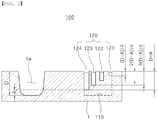
- FIG. 2 is a schematic cross-sectional view of the tire facilitating a check of wear condition according to the first embodiment of the present invention, which is formed by applying the first mold of FIG. 1 to a tread.
- the tire facilitating a check of wear condition includes a wear mark 100 engraved in the tread 1 to provide information on a degree of wear of the tread 1.
- the wear mark 100 is formed in the tread 1 by the first mold 100'.
- the wear mark 100 includes guide groove parts 110 and an indicator groove part 120, wherein the guide groove parts 110 are formed in pair with being engraved in the tread 1 to be symmetric to each other with a predetermined_ distance therebetween, and the indicator groove part 120 is formed with being engraved between the guide groove parts 110 in the tread 1 with a difference in depths from one side to the other side in the length direction.
- the guide groove parts 110 are preferably formed in a sandglass shape in the tread 1 by the first molding parts 110', and a depth of the guide groove part 110 may be identical to or shallower than a wear threshold (D-A) of the tread 1, that is, a depth of a groove 1a thereof.
- D-A wear threshold
- the indicator groove part 120 includes a plurality of grooves in the tread 1 by the second molding part 120', and the grooves are formed with a difference in depths for each stage from one side to the other side of the guide groove part 110 at a predetermined distance.
- the indicator groove part 120 includes a first groove 121 formed by the first molding protrusion 121', a second groove 122 formed by the second molding protrusion 122', a third groove 123 formed by the third molding protrusion 123', and a fourth groove 124 formed by the fourth molding protrusion 124'.
- the first groove 121 is formed at a depth of (D-A)/4 within the wear threshold (D-A), and the second groove 122 is formed at a depth of 2(D-A)/4 within the wear threshold (D-A) .
- the third groove 123 is formed at a depth of 3(D-A)/4 within the wear threshold (D-A), and the fourth groove 124 is formed at a depth of the wear threshold (D-A).
- the indicator groove part 120 has a difference in depths for each stage in order to be worn out in an order from one side toward the other side of the guide groove part 110 according to the degree of wear of the tread 1.
- the wear condition of the tire can be checked through the indicator groove part 120, and the degree of wear of the tire can be recognized by depths of the first to fourth grooves 121 to 124 in an order from the first groove to the fourth groove.
- FIGS. 3(a) to (e) are schematic views illustrating use states in an order of wear of the tire facilitating a check of wear condition according to the first embodiment of the present invention of FIG. 2 .
- the wear mark 100 is formed with being engraved in the tread 1 by the first mold 100' illustrated in FIG. 1 .
- the guide groove part 110 and the indicator groove part 120 are formed in the tread 1, and the indicator groove part 120 is worn out from one side toward the other side of the guide groove part 120 according to the degree of wear of the tread 1.
- the indicator groove part 120 is worn out in an order from FIG. 3(a) to FIG. 3(b) , from FIG. 3(b) to FIG. 3(c) , from FIG. 3(c) to FIG. 3(d) , from FIG. 3(d) to FIG. 3(e) , and in the case of FIG. 3(e) , it shows that the tire needs to be replaced for safe driving of the vehicle, as the indicator groove part 120 is completely worn out to reach the wear threshold.
- the wear mark 100 is preferably formed in a sandglass shape, thus has a visual effect of indicating the wear of the tread 1 in progress.
- FIGS. 4(a) to (d) are schematic views of a second mold provided to implement a tire facilitating a check of wear condition according to a second embodiment of the present invention.
- a second mold 200' includes a plate 200a', first molding parts 210', and a second molding part 220'.
- the second mold 200' is different only in a shape of the second molding part 220'.
- the second molding part 220' is formed in an inclined shape from one side to the other side of the first molding part 210', and a projection molding groove 220a' is formed on one side of the second molding part 220' to form a projection member 220a to be described below in the tread 1.
- the second molding part 220' has a shape in which a middle portion thereof that is separated from a position of a concave portion 210a formed in the first molding part 210' is inclined to the other side thereof.
- the second mold 200' of FIG. 4 is quite similar to that described with reference to FIG. 1 , therefore will not be described in detail.
- FIG. 5 is a schematic cross-sectional view of the tire facilitating a check of wear condition according to the second embodiment of the present invention, which is formed by applying the second mold of FIG. 4 to a tread.
- the tire facilitating a check of wear condition includes a wear mark 200 engraved in the tread 1 to provide information on a degree of wear of the tread 1, and the wear mart 200 includes guide groove parts 210 and an indicator groove part 220.
- the wear mark 200 is engraved in such a way that the second mold 200' is applied to the tread 1 so that the wear mark 200 is formed therein.
- the wear mark 200 is different only in a shape of the indicator groove part 220.
- the indicator groove part 220 includes one groove, and the groove has a difference in depths from one side to the other side of the guide groove part 210 so that the tread 1 is formed in an inclined shape.
- a wear threshold may be D-A.
- the guide groove part 210 is processed to have an inclined surface, and a curved surface of the inclined surface is formed with being engraved so that the curved surface is inclined by a depth of 3(D-A)/4 within the wear threshold (D-A).
- the groove is formed on the other side of the guide groove part 210 with being engraved so that the projection member 220a is formed in the tread 1 to display a warning symbol at the time of reaching the wear threshold of the tread 1.
- the indicator groove part 220 is formed in the inclined shape with a difference in depths in order to be gradually worn out in an order from one side toward the other side of the guide groove part 210 according to the degree of wear of the tread 1.
- the wear mark 200 of FIG. 5 is the same as that described with reference to FIG. 3 , therefore will not be described in detail.
- FIGS. 6(a) to (e) are schematic views illustrating use states in an order of wear of the tire facilitating a check of wear condition according to the second embodiment of the present invention of FIG. 5 .
- the wear mark 200 is formed with being engraved in the tread 1 by the first mold 200' illustrated in FIG. 4 .
- the indicator groove part 220 is worn out in an order from FIG. 6(a) to FIG. 6(b) , from FIG. 6(b) to FIG. 6(c) , from FIG. 6(c) to FIG. 6(d) , from FIG. 6(d) to FIG. 6(e) , and in the case of FIG. 6(e) , it shows that the tire needs to be replaced for safe driving of the vehicle, as the indicator groove part 220 is completely worn out to reach the wear threshold.
- the projection member 220a is shown while a warning symbol of e.g. "! shape appears.
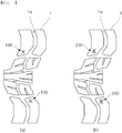
- FIGS. 7(a) and (b) are schematic views illustrating use states of the tires facilitating a check of wear condition according to the first and second embodiments of the present invention.
- the wear marks 100 and 200 may be formed at any portion with being engraved in the tread 1 contacting a road surface.
Landscapes
- Engineering & Computer Science (AREA)
- Mechanical Engineering (AREA)
- Tires In General (AREA)
- Moulds For Moulding Plastics Or The Like (AREA)
Abstract
Description
- The present invention relates to a tire facilitating a check of wear condition, and more particularly, to a tire facilitating a check of wear condition capable of estimating a replacement time of a tire by recognizing information on wear condition of the tire.
- In accordance with recent development of vehicle industries, development of a tire industry field has also been accelerated. Products optimized for each condition such as road condition, weather, a type of vehicle, fuel efficiency, connectivity with IT devices, and the like have been developed from a simple functional purpose of a circular wheel of simply rolling to move, and have been released. To this end, detailed elements with functional purpose in a tire have been increased. One of the elements is a wear level information display device.
- A wear level for evaluating how long the tire can be used is one of important performances of the tire. Information on wear of a tire is essential in order for a user to safely drive from a time when the user buys the tire until the tire is used for driving of a certain distance and discarded.
- In order to effectively deliver the information to the user, display devices are applied to a tire. Generally, the tire can sufficiently support a load of a vehicle and absorb and attenuate shock from a road surface, and sufficiently transfer a driving force, a braking force, a lateral force, and the like.
- Further, in order to prevent a decrease in functions of the driving force, the braking force, and the lateral force of the tire, a check of wear condition of the tire should be essentially performed.
- If a vehicle is driven with an excessively worn tire, hydroplaning may easily occur on a wet road, and a braking distance on a road surface is increased, thereby causing a vehicle accident.
- As an example of a related art, Korean Patent Laid-Open Publication No.
10-1997-0020488 - However, the apparatus for checking wear condition of a tire of the related art is disadvantageous in that the user cannot frequently check the condition of the tire regardless of place and time as necessary.
- (Patent Document 1) Korean Patent Laid-Open Publication No.
10-1997-0020488 - In consideration of the above-mentioned circumstances, it is an object of the present invention to provide a tire facilitating a check of wear condition that allows a user to visually check a progress of wear and information on a wear threshold of the tire.
- Another object of the present invention is to provide a tire facilitating a check of wear condition that may significantly reduce defects by applying a mold with a simple shape in a vertical direction to prevent a tearing phenomenon during mass production of tires.
- In order to achieve the above-described object, according to the present invention, there is provided a tire facilitating a check of wear condition, including: a wear mark which is engraved in a tread to provide information on a degree of wear of the tread, wherein the wear mark includes: a pair of guide groove parts which are formed in the tread with being engraved so as to be symmetric to each other with a predetermined distance therebetween; and an indicator groove part which is formed in the tread with being engraved while having a depth increased from one side toward the other side in a longitudinal direction between the guide groove parts. Throughout the specification and the claims the term "depth" is meant to indicate the distance measured from the road contact surface of the tire radially into the tire.
- In the present invention, a depth of the guide groove part may be identical to or shallower than a depth of a groove of the tread.
- In the present invention, the guide groove part may preferably be formed to have a curved shape forming a sandglass shape in the tread.
- In the present invention, the indicator groove part may include a plurality, i.e. 1, 2, 3, or more of grooves, and the grooves may be formed with a difference in depths for each stage from one side to the other side of the guide groove part at a predetermined distance.
- In the present invention, the indicator groove part may include one groove, and the groove may be formed in an inclined shape so as to have a difference in depths from one side to the other side of the guide groove part.
- In the present invention, the groove formed on the other side of the guide groove part may have a projection member which is formed in the tread so as to display a warning symbol at the time of reaching a wear threshold of the tread.
- According to the tire facilitating a check of wear condition in accordance with the present invention, a plurality of wear marks formed in a tread are worn and worn out in stages, thereby allowing a user to visually check information on a degree of wear of the tire.
-
-
FIGS. 1(a) to (d) are schematic views of a first mold provided to implement a tire facilitating a check of wear condition according to a first embodiment of the present invention. -
FIG. 2 is a schematic cross-sectional view of the tire facilitating a check of wear condition according to the first embodiment of the present invention, which is formed by applying the first mold ofFIG. 1 to a tread. -
FIGS. 3(a) to (e) are schematic views illustrating use states in an order of wear of the tire facilitating a check of wear condition according to the first embodiment of the present invention ofFIG. 2 . -
FIGS. 4(a) to (d) are schematic views of a second mold provided to implement a tire facilitating a check of wear condition according to a second embodiment of the present invention. -
FIG. 5 is a schematic cross-sectional view of the tire facilitating a check of wear condition according to the second embodiment of the present invention, which is formed by applying the second mold ofFIG. 4 to the tread. -
FIGS. 6(a) to (e) are schematic views illustrating use states in an order of wear of the tire facilitating a check of wear condition according to the second embodiment of the present invention ofFIG. 5 . -
FIGS. 7(a) and (b) are schematic views illustrating use states of the tires facilitating a check of wear condition according to the first and second embodiments of the present invention. - Hereinafter, preferred embodiments of the present invention will be described in terms of a configuration and an operation thereof with reference to the accompanying drawings in detail. In describing the present invention, to facilitate overall understanding, identical reference numerals will be denoted to portions performing similar functions and operations throughout the accompanying drawings, and the identical components will not be described.
-
FIGS. 1(a) to (d) are schematic views of a first mold provided to implement a tire facilitating a check of wear condition according to a first embodiment of the present invention. - As illustrated in
FIG. 1 , a first mold 100' includes aplate 100a', first molding parts 110', and a second molding part 120'. - The
plate 100a' is formed in a flat-plate shape. - The first molding parts 110' extend in an erected shape from the
plate 100a', are formed in pair to be symmetric to each other with a predetermined distance therebetween. In addition, the first molding parts 110' are preferably formed in a sandglass shape in which middle portions thereof are concavely bent in directions opposite to each other. - The second molding part 120' is disposed between the first molding parts 110', extends in an erected shape from the
plate 100a', and is formed with a difference in lengths from one side to the other side in a longitudinal direction of the first molding part 110'. - The second molding part 120' may include a first molding protrusion 121' positioned on one side of the first molding part 110', a second molding protrusion 122' that is separated toward the other side of the first molding part 110' from the first molding protrusion 121', a third molding protrusion 123' that is separated toward the other side of the first molding part 110' from the second molding protrusion 122', and a fourth molding protrusion 124' that is separated toward the other side of the first molding part 110' from the third molding protrusion 123'.
- The second molding part 120' including the first to fourth molding protrusions 121', 122', 123' and 124' is merely illustrated as an example, thus a configuration of the second molding part 120' is not limited thereto, but may be formed in various shapes.
- Using the first mold 100' is to significantly reduce defects by a simple shape to prevent a tearing phenomenon during mass production of a tire with being engraved in a
tread 1 to be described below. -
FIG. 2 is a schematic cross-sectional view of the tire facilitating a check of wear condition according to the first embodiment of the present invention, which is formed by applying the first mold ofFIG. 1 to a tread. - As illustrated in
FIG. 2 , the tire facilitating a check of wear condition includes awear mark 100 engraved in thetread 1 to provide information on a degree of wear of thetread 1. - The
wear mark 100 is formed in thetread 1 by the first mold 100'. - The
wear mark 100 includesguide groove parts 110 and anindicator groove part 120, wherein theguide groove parts 110 are formed in pair with being engraved in thetread 1 to be symmetric to each other with a predetermined_ distance therebetween, and theindicator groove part 120 is formed with being engraved between theguide groove parts 110 in thetread 1 with a difference in depths from one side to the other side in the length direction. - As described above with reference to
FIG. 1 , theguide groove parts 110 are preferably formed in a sandglass shape in thetread 1 by the first molding parts 110', and a depth of theguide groove part 110 may be identical to or shallower than a wear threshold (D-A) of thetread 1, that is, a depth of agroove 1a thereof. - As described above with reference to
FIG. 1 , theindicator groove part 120 includes a plurality of grooves in thetread 1 by the second molding part 120', and the grooves are formed with a difference in depths for each stage from one side to the other side of theguide groove part 110 at a predetermined distance. - The
indicator groove part 120 includes afirst groove 121 formed by the first molding protrusion 121', asecond groove 122 formed by the second molding protrusion 122', athird groove 123 formed by the third molding protrusion 123', and afourth groove 124 formed by the fourth molding protrusion 124'. - The
first groove 121 is formed at a depth of (D-A)/4 within the wear threshold (D-A), and thesecond groove 122 is formed at a depth of 2(D-A)/4 within the wear threshold (D-A) . - Further, the
third groove 123 is formed at a depth of 3(D-A)/4 within the wear threshold (D-A), and thefourth groove 124 is formed at a depth of the wear threshold (D-A). - The
indicator groove part 120 has a difference in depths for each stage in order to be worn out in an order from one side toward the other side of theguide groove part 110 according to the degree of wear of thetread 1. - Accordingly, the wear condition of the tire can be checked through the
indicator groove part 120, and the degree of wear of the tire can be recognized by depths of the first tofourth grooves 121 to 124 in an order from the first groove to the fourth groove. -
FIGS. 3(a) to (e) are schematic views illustrating use states in an order of wear of the tire facilitating a check of wear condition according to the first embodiment of the present invention ofFIG. 2 . - The
wear mark 100 is formed with being engraved in thetread 1 by the first mold 100' illustrated inFIG. 1 . - As illustrated in
FIG. 3 , theguide groove part 110 and theindicator groove part 120 are formed in thetread 1, and theindicator groove part 120 is worn out from one side toward the other side of theguide groove part 120 according to the degree of wear of thetread 1. - The
indicator groove part 120 is worn out in an order fromFIG. 3(a) to FIG. 3(b) , fromFIG. 3(b) to FIG. 3(c) , fromFIG. 3(c) to FIG. 3(d) , fromFIG. 3(d) to FIG. 3(e) , and in the case ofFIG. 3(e) , it shows that the tire needs to be replaced for safe driving of the vehicle, as theindicator groove part 120 is completely worn out to reach the wear threshold. - Further, the
wear mark 100 is preferably formed in a sandglass shape, thus has a visual effect of indicating the wear of thetread 1 in progress. -
FIGS. 4(a) to (d) are schematic views of a second mold provided to implement a tire facilitating a check of wear condition according to a second embodiment of the present invention. - As illustrated in
FIG. 4 , a second mold 200' includes aplate 200a', first molding parts 210', and a second molding part 220'. - When comparing with the first mold 100' of
FIG. 1 , the second mold 200' is different only in a shape of the second molding part 220'. - The second molding part 220' is formed in an inclined shape from one side to the other side of the first molding part 210', and a
projection molding groove 220a' is formed on one side of the second molding part 220' to form aprojection member 220a to be described below in thetread 1. - The second molding part 220' has a shape in which a middle portion thereof that is separated from a position of a
concave portion 210a formed in the first molding part 210' is inclined to the other side thereof. - In terms of a shape and a technical configuration, the second mold 200' of
FIG. 4 is quite similar to that described with reference toFIG. 1 , therefore will not be described in detail. -
FIG. 5 is a schematic cross-sectional view of the tire facilitating a check of wear condition according to the second embodiment of the present invention, which is formed by applying the second mold ofFIG. 4 to a tread. - As illustrated in
FIG. 5 , the tire facilitating a check of wear condition includes awear mark 200 engraved in thetread 1 to provide information on a degree of wear of thetread 1, and thewear mart 200 includesguide groove parts 210 and anindicator groove part 220. - The
wear mark 200 is engraved in such a way that the second mold 200' is applied to thetread 1 so that thewear mark 200 is formed therein. - When comparing with the
wear mark 100 illustrated inFIG. 2 , thewear mark 200 is different only in a shape of theindicator groove part 220. - The
indicator groove part 220 includes one groove, and the groove has a difference in depths from one side to the other side of theguide groove part 210 so that thetread 1 is formed in an inclined shape. - Further, when a depth of the
groove 1a is D, a wear threshold may be D-A. Theguide groove part 210 is processed to have an inclined surface, and a curved surface of the inclined surface is formed with being engraved so that the curved surface is inclined by a depth of 3(D-A)/4 within the wear threshold (D-A). - Further, the groove is formed on the other side of the
guide groove part 210 with being engraved so that theprojection member 220a is formed in thetread 1 to display a warning symbol at the time of reaching the wear threshold of thetread 1. - The
indicator groove part 220 is formed in the inclined shape with a difference in depths in order to be gradually worn out in an order from one side toward the other side of theguide groove part 210 according to the degree of wear of thetread 1. - In terms of a technical configuration, a shape, and an organic combination thereof, the
wear mark 200 ofFIG. 5 is the same as that described with reference toFIG. 3 , therefore will not be described in detail. -
FIGS. 6(a) to (e) are schematic views illustrating use states in an order of wear of the tire facilitating a check of wear condition according to the second embodiment of the present invention ofFIG. 5 . - The
wear mark 200 is formed with being engraved in thetread 1 by the first mold 200' illustrated inFIG. 4 . - As illustrated in
FIG. 6 , theindicator groove part 220 is worn out in an order fromFIG. 6(a) to FIG. 6(b) , fromFIG. 6(b) to FIG. 6(c) , fromFIG. 6(c) to FIG. 6(d) , fromFIG. 6(d) to FIG. 6(e) , and in the case ofFIG. 6(e) , it shows that the tire needs to be replaced for safe driving of the vehicle, as theindicator groove part 220 is completely worn out to reach the wear threshold. - To prevent the wear of the
tread 1 from further advancing, theprojection member 220a is shown while a warning symbol of e.g. "!" shape appears. -
FIGS. 7(a) and (b) are schematic views illustrating use states of the tires facilitating a check of wear condition according to the first and second embodiments of the present invention. - The wear marks 100 and 200 may be formed at any portion with being engraved in the
tread 1 contacting a road surface. - While the present invention has been described with reference to the preferred embodiments and modified examples, the present invention is not limited to the above-described specific embodiments and the modified examples, and it will be understood by those skilled in the related art that various modifications and variations may be made therein without departing from the scope of the present invention as defined by the appended claims, as well as these modifications and variations should not be understood separately from the technical spirit and prospect of the present invention.
-
- 100': first mold, 200': second mold
- 100'a, 200'a: plate, 110', 210': first molding part
- 120, 220': second molding part, 121': first molding protrusion
- 122': second molding protrusion, 123': third molding protrusion
- 124': fourth molding protrusion, 220a': projection molding groove
- 1: tread, 1a: groove
- 100,200: wear mark, 110, 210: guide groove part
- 110a, 210a: concave portion, 120, 220: indicator groove part
- 121: first groove, 122: second groove
- 123: third groove, 124: fourth groove
- 220a: projection member
Claims (6)
- A tire facilitating a check of wear condition, comprising:a wear mark which is engraved in a tread to provide information on a degree of wear of the tread,wherein the wear mark comprises:a pair of guide groove parts which are formed in the tread with being engraved so as to be symmetric to each other with a distance therebetween; andan indicator groove part which is formed in the tread with being engraved while having a depth increased from one side toward the other side in a longitudinal direction between the guide groove parts.
- The tire facilitating a check of wear condition of claim 1, wherein a depth of the guide groove part is identical to or shallower than a depth of a groove of the tread.
- The tire facilitating a check of wear condition of claim 1 or 2, wherein the guide groove part is formed to have a curved shape forming a sandglass shape in the tread.
- The tire facilitating a check of wear condition of claim 1, 2 or 3, wherein the indicator groove part includes a plurality of grooves, and
the grooves are formed with a difference in depths for each stage from one side to the other side of the guide groove part at a distance. - The tire facilitating a check of wear condition of claim 1, 2 or 3, wherein the indicator groove part includes one groove, and
the groove is formed in an inclined shape so as to have a difference in depths from one side to the other side of the guide groove part. - The tire facilitating a check of wear condition of claim 5, wherein the groove formed on the other side of the guide groove part has a projection member which is formed in the tread so as to display a warning symbol at the time of reaching a wear threshold of the tread.
Applications Claiming Priority (1)
| Application Number | Priority Date | Filing Date | Title |
|---|---|---|---|
| KR1020160128268A KR101911823B1 (en) | 2016-10-05 | 2016-10-05 | Easy tire to check the wear state |
Publications (2)
| Publication Number | Publication Date |
|---|---|
| EP3305560A1 true EP3305560A1 (en) | 2018-04-11 |
| EP3305560B1 EP3305560B1 (en) | 2019-08-28 |
Family
ID=59923299
Family Applications (1)
| Application Number | Title | Priority Date | Filing Date |
|---|---|---|---|
| EP17192061.4A Active EP3305560B1 (en) | 2016-10-05 | 2017-09-20 | Tire facilitating a check of the wear condition |
Country Status (3)
| Country | Link |
|---|---|
| EP (1) | EP3305560B1 (en) |
| KR (1) | KR101911823B1 (en) |
| CN (1) | CN107914521B (en) |
Families Citing this family (3)
| Publication number | Priority date | Publication date | Assignee | Title |
|---|---|---|---|---|
| KR20210001643U (en) | 2020-01-08 | 2021-07-16 | 한국타이어앤테크놀로지 주식회사 | Wear index block using pattern block shape |
| KR102409036B1 (en) * | 2020-11-17 | 2022-06-16 | 넥센타이어 주식회사 | Bicycle tire for easy recognition of wear |
| CN117416159A (en) * | 2023-11-03 | 2024-01-19 | 山东玲珑轮胎股份有限公司 | A vehicle pneumatic tire |
Citations (5)
| Publication number | Priority date | Publication date | Assignee | Title |
|---|---|---|---|---|
| KR970020488A (en) | 1995-10-31 | 1997-05-28 | 배순훈 | Tire wear check device |
| JP2006232152A (en) * | 2005-02-25 | 2006-09-07 | Bridgestone Corp | Tire |
| US20150035971A1 (en) * | 2012-04-19 | 2015-02-05 | Continental Reifen Deutschland Gmbh | Method for determining the tread depth of a vehicle pneumatic tire |
| DE102014217151A1 (en) * | 2014-08-28 | 2016-03-03 | Continental Reifen Deutschland Gmbh | Vehicle tires |
| JP2016159712A (en) * | 2015-02-27 | 2016-09-05 | 横浜ゴム株式会社 | Pneumatic tire |
Family Cites Families (8)
| Publication number | Priority date | Publication date | Assignee | Title |
|---|---|---|---|---|
| DE3627832A1 (en) * | 1986-08-16 | 1988-02-18 | Continental Gummi Werke Ag | Pneumatic vehicle tyre having a wear indicator |
| JPH1076814A (en) * | 1996-09-03 | 1998-03-24 | Takashi Morita | Tire which indicates wear by color |
| KR20010036391A (en) * | 1999-10-08 | 2001-05-07 | 조충환 | Wear limit indicator for tire |
| CN2759814Y (en) * | 2004-11-26 | 2006-02-22 | 诺基安轮胎有限公司 | Wear indicator used for vehicle tire |
| KR200419721Y1 (en) * | 2005-12-20 | 2006-06-23 | 노키안 타이어스 피엘씨 | Wear indicators for vehicle tires |
| CN201148104Y (en) * | 2007-07-25 | 2008-11-12 | 东莞市贝司通橡胶有限公司 | Motor vehicle tyre with wear warning mark |
| FR3010349A1 (en) * | 2013-09-11 | 2015-03-13 | Michelin & Cie | TIRE DESIGNED AS EVOLUTIVE ASYMMETRIC SCULPTURE |
| JP6557996B2 (en) * | 2015-03-04 | 2019-08-14 | 横浜ゴム株式会社 | Pneumatic tire |
-
2016
- 2016-10-05 KR KR1020160128268A patent/KR101911823B1/en active Active
-
2017
- 2017-09-20 EP EP17192061.4A patent/EP3305560B1/en active Active
- 2017-09-27 CN CN201710892710.3A patent/CN107914521B/en active Active
Patent Citations (5)
| Publication number | Priority date | Publication date | Assignee | Title |
|---|---|---|---|---|
| KR970020488A (en) | 1995-10-31 | 1997-05-28 | 배순훈 | Tire wear check device |
| JP2006232152A (en) * | 2005-02-25 | 2006-09-07 | Bridgestone Corp | Tire |
| US20150035971A1 (en) * | 2012-04-19 | 2015-02-05 | Continental Reifen Deutschland Gmbh | Method for determining the tread depth of a vehicle pneumatic tire |
| DE102014217151A1 (en) * | 2014-08-28 | 2016-03-03 | Continental Reifen Deutschland Gmbh | Vehicle tires |
| JP2016159712A (en) * | 2015-02-27 | 2016-09-05 | 横浜ゴム株式会社 | Pneumatic tire |
Also Published As
| Publication number | Publication date |
|---|---|
| EP3305560B1 (en) | 2019-08-28 |
| KR20180037726A (en) | 2018-04-13 |
| KR101911823B1 (en) | 2019-01-04 |
| CN107914521A (en) | 2018-04-17 |
| CN107914521B (en) | 2019-12-03 |
Similar Documents
| Publication | Publication Date | Title |
|---|---|---|
| CN102046398B (en) | tires for driving on ice | |
| US12083829B2 (en) | Three-dimensional tire sipe | |
| EP3305560A1 (en) | Tire facilitating a check of the wear condition | |
| EP3594024B1 (en) | Tire | |
| US9616715B2 (en) | Tread for tire of a drive axle of a heavy goods vehicle and tire | |
| EP2329967A1 (en) | Tire tread wear indicator and molding device therefore | |
| KR20060053205A (en) | Tire tread and molding device | |
| CN107107671B (en) | tire attachment elements | |
| CN104853936A (en) | Optimal tire performance indicator | |
| EP3335909A1 (en) | A pneumatic tire, a tread band, and a tread block comprising a sipe, and a lamella plate for the manufacture thereof | |
| JP2018069859A (en) | tire | |
| WO2015134158A1 (en) | Tire tread featuring a sipe | |
| JP2015171865A (en) | tire | |
| EP2517867A1 (en) | Blade for a mold, mold segment or mold comprising such a blade and method of securing a mold blade to a mold segment | |
| RU2015121952A (en) | MARKING SIGNS ON TIRE SIDES DECREASING THE AERODYNAMIC RESISTANCE | |
| JP5769427B2 (en) | Pneumatic tire | |
| US10864777B2 (en) | Tire wear monitoring device | |
| JP5454165B2 (en) | Tire molding mold and pneumatic tire | |
| WO2018078937A1 (en) | Stud pin and pneumatic tire provided with stud pin | |
| US20180354313A1 (en) | Tire Tread Comprising Incisions | |
| RU2579386C2 (en) | Antiskid stud | |
| KR20070055872A (en) | Pneumatic tire | |
| US1619426A (en) | Tire tool | |
| CN104742663A (en) | Tire with abrasion pits | |
| US20240399796A1 (en) | Three-dimensional tire sipe |
Legal Events
| Date | Code | Title | Description |
|---|---|---|---|
| PUAI | Public reference made under article 153(3) epc to a published international application that has entered the european phase |
Free format text: ORIGINAL CODE: 0009012 |
|
| STAA | Information on the status of an ep patent application or granted ep patent |
Free format text: STATUS: THE APPLICATION HAS BEEN PUBLISHED |
|
| AK | Designated contracting states |
Kind code of ref document: A1 Designated state(s): AL AT BE BG CH CY CZ DE DK EE ES FI FR GB GR HR HU IE IS IT LI LT LU LV MC MK MT NL NO PL PT RO RS SE SI SK SM TR |
|
| AX | Request for extension of the european patent |
Extension state: BA ME |
|
| STAA | Information on the status of an ep patent application or granted ep patent |
Free format text: STATUS: REQUEST FOR EXAMINATION WAS MADE |
|
| 17P | Request for examination filed |
Effective date: 20181011 |
|
| RBV | Designated contracting states (corrected) |
Designated state(s): AL AT BE BG CH CY CZ DE DK EE ES FI FR GB GR HR HU IE IS IT LI LT LU LV MC MK MT NL NO PL PT RO RS SE SI SK SM TR |
|
| GRAP | Despatch of communication of intention to grant a patent |
Free format text: ORIGINAL CODE: EPIDOSNIGR1 |
|
| STAA | Information on the status of an ep patent application or granted ep patent |
Free format text: STATUS: GRANT OF PATENT IS INTENDED |
|
| INTG | Intention to grant announced |
Effective date: 20190329 |
|
| GRAS | Grant fee paid |
Free format text: ORIGINAL CODE: EPIDOSNIGR3 |
|
| GRAA | (expected) grant |
Free format text: ORIGINAL CODE: 0009210 |
|
| STAA | Information on the status of an ep patent application or granted ep patent |
Free format text: STATUS: THE PATENT HAS BEEN GRANTED |
|
| AK | Designated contracting states |
Kind code of ref document: B1 Designated state(s): AL AT BE BG CH CY CZ DE DK EE ES FI FR GB GR HR HU IE IS IT LI LT LU LV MC MK MT NL NO PL PT RO RS SE SI SK SM TR |
|
| REG | Reference to a national code |
Ref country code: GB Ref legal event code: FG4D |
|
| REG | Reference to a national code |
Ref country code: CH Ref legal event code: EP |
|
| REG | Reference to a national code |
Ref country code: AT Ref legal event code: REF Ref document number: 1171961 Country of ref document: AT Kind code of ref document: T Effective date: 20190915 |
|
| REG | Reference to a national code |
Ref country code: IE Ref legal event code: FG4D |
|
| REG | Reference to a national code |
Ref country code: DE Ref legal event code: R096 Ref document number: 602017006504 Country of ref document: DE |
|
| REG | Reference to a national code |
Ref country code: SE Ref legal event code: TRGR |
|
| REG | Reference to a national code |
Ref country code: NL Ref legal event code: MP Effective date: 20190828 |
|
| REG | Reference to a national code |
Ref country code: LT Ref legal event code: MG4D |
|
| PG25 | Lapsed in a contracting state [announced via postgrant information from national office to epo] |
Ref country code: NL Free format text: LAPSE BECAUSE OF FAILURE TO SUBMIT A TRANSLATION OF THE DESCRIPTION OR TO PAY THE FEE WITHIN THE PRESCRIBED TIME-LIMIT Effective date: 20190828 Ref country code: PT Free format text: LAPSE BECAUSE OF FAILURE TO SUBMIT A TRANSLATION OF THE DESCRIPTION OR TO PAY THE FEE WITHIN THE PRESCRIBED TIME-LIMIT Effective date: 20191230 Ref country code: HR Free format text: LAPSE BECAUSE OF FAILURE TO SUBMIT A TRANSLATION OF THE DESCRIPTION OR TO PAY THE FEE WITHIN THE PRESCRIBED TIME-LIMIT Effective date: 20190828 Ref country code: NO Free format text: LAPSE BECAUSE OF FAILURE TO SUBMIT A TRANSLATION OF THE DESCRIPTION OR TO PAY THE FEE WITHIN THE PRESCRIBED TIME-LIMIT Effective date: 20191128 Ref country code: FI Free format text: LAPSE BECAUSE OF FAILURE TO SUBMIT A TRANSLATION OF THE DESCRIPTION OR TO PAY THE FEE WITHIN THE PRESCRIBED TIME-LIMIT Effective date: 20190828 Ref country code: BG Free format text: LAPSE BECAUSE OF FAILURE TO SUBMIT A TRANSLATION OF THE DESCRIPTION OR TO PAY THE FEE WITHIN THE PRESCRIBED TIME-LIMIT Effective date: 20191128 Ref country code: LT Free format text: LAPSE BECAUSE OF FAILURE TO SUBMIT A TRANSLATION OF THE DESCRIPTION OR TO PAY THE FEE WITHIN THE PRESCRIBED TIME-LIMIT Effective date: 20190828 |
|
| PG25 | Lapsed in a contracting state [announced via postgrant information from national office to epo] |
Ref country code: IS Free format text: LAPSE BECAUSE OF FAILURE TO SUBMIT A TRANSLATION OF THE DESCRIPTION OR TO PAY THE FEE WITHIN THE PRESCRIBED TIME-LIMIT Effective date: 20191228 Ref country code: ES Free format text: LAPSE BECAUSE OF FAILURE TO SUBMIT A TRANSLATION OF THE DESCRIPTION OR TO PAY THE FEE WITHIN THE PRESCRIBED TIME-LIMIT Effective date: 20190828 Ref country code: RS Free format text: LAPSE BECAUSE OF FAILURE TO SUBMIT A TRANSLATION OF THE DESCRIPTION OR TO PAY THE FEE WITHIN THE PRESCRIBED TIME-LIMIT Effective date: 20190828 Ref country code: GR Free format text: LAPSE BECAUSE OF FAILURE TO SUBMIT A TRANSLATION OF THE DESCRIPTION OR TO PAY THE FEE WITHIN THE PRESCRIBED TIME-LIMIT Effective date: 20191129 Ref country code: AL Free format text: LAPSE BECAUSE OF FAILURE TO SUBMIT A TRANSLATION OF THE DESCRIPTION OR TO PAY THE FEE WITHIN THE PRESCRIBED TIME-LIMIT Effective date: 20190828 Ref country code: LV Free format text: LAPSE BECAUSE OF FAILURE TO SUBMIT A TRANSLATION OF THE DESCRIPTION OR TO PAY THE FEE WITHIN THE PRESCRIBED TIME-LIMIT Effective date: 20190828 |
|
| REG | Reference to a national code |
Ref country code: AT Ref legal event code: MK05 Ref document number: 1171961 Country of ref document: AT Kind code of ref document: T Effective date: 20190828 |
|
| PG25 | Lapsed in a contracting state [announced via postgrant information from national office to epo] |
Ref country code: TR Free format text: LAPSE BECAUSE OF FAILURE TO SUBMIT A TRANSLATION OF THE DESCRIPTION OR TO PAY THE FEE WITHIN THE PRESCRIBED TIME-LIMIT Effective date: 20190828 |
|
| PG25 | Lapsed in a contracting state [announced via postgrant information from national office to epo] |
Ref country code: PL Free format text: LAPSE BECAUSE OF FAILURE TO SUBMIT A TRANSLATION OF THE DESCRIPTION OR TO PAY THE FEE WITHIN THE PRESCRIBED TIME-LIMIT Effective date: 20190828 Ref country code: RO Free format text: LAPSE BECAUSE OF FAILURE TO SUBMIT A TRANSLATION OF THE DESCRIPTION OR TO PAY THE FEE WITHIN THE PRESCRIBED TIME-LIMIT Effective date: 20190828 Ref country code: EE Free format text: LAPSE BECAUSE OF FAILURE TO SUBMIT A TRANSLATION OF THE DESCRIPTION OR TO PAY THE FEE WITHIN THE PRESCRIBED TIME-LIMIT Effective date: 20190828 Ref country code: AT Free format text: LAPSE BECAUSE OF FAILURE TO SUBMIT A TRANSLATION OF THE DESCRIPTION OR TO PAY THE FEE WITHIN THE PRESCRIBED TIME-LIMIT Effective date: 20190828 Ref country code: DK Free format text: LAPSE BECAUSE OF FAILURE TO SUBMIT A TRANSLATION OF THE DESCRIPTION OR TO PAY THE FEE WITHIN THE PRESCRIBED TIME-LIMIT Effective date: 20190828 Ref country code: IT Free format text: LAPSE BECAUSE OF FAILURE TO SUBMIT A TRANSLATION OF THE DESCRIPTION OR TO PAY THE FEE WITHIN THE PRESCRIBED TIME-LIMIT Effective date: 20190828 |
|
| PG25 | Lapsed in a contracting state [announced via postgrant information from national office to epo] |
Ref country code: IS Free format text: LAPSE BECAUSE OF FAILURE TO SUBMIT A TRANSLATION OF THE DESCRIPTION OR TO PAY THE FEE WITHIN THE PRESCRIBED TIME-LIMIT Effective date: 20200224 Ref country code: SM Free format text: LAPSE BECAUSE OF FAILURE TO SUBMIT A TRANSLATION OF THE DESCRIPTION OR TO PAY THE FEE WITHIN THE PRESCRIBED TIME-LIMIT Effective date: 20190828 Ref country code: CZ Free format text: LAPSE BECAUSE OF FAILURE TO SUBMIT A TRANSLATION OF THE DESCRIPTION OR TO PAY THE FEE WITHIN THE PRESCRIBED TIME-LIMIT Effective date: 20190828 Ref country code: MC Free format text: LAPSE BECAUSE OF FAILURE TO SUBMIT A TRANSLATION OF THE DESCRIPTION OR TO PAY THE FEE WITHIN THE PRESCRIBED TIME-LIMIT Effective date: 20190828 Ref country code: SK Free format text: LAPSE BECAUSE OF FAILURE TO SUBMIT A TRANSLATION OF THE DESCRIPTION OR TO PAY THE FEE WITHIN THE PRESCRIBED TIME-LIMIT Effective date: 20190828 |
|
| REG | Reference to a national code |
Ref country code: DE Ref legal event code: R097 Ref document number: 602017006504 Country of ref document: DE |
|
| PLBE | No opposition filed within time limit |
Free format text: ORIGINAL CODE: 0009261 |
|
| STAA | Information on the status of an ep patent application or granted ep patent |
Free format text: STATUS: NO OPPOSITION FILED WITHIN TIME LIMIT |
|
| PG2D | Information on lapse in contracting state deleted |
Ref country code: IS |
|
| PG25 | Lapsed in a contracting state [announced via postgrant information from national office to epo] |
Ref country code: IE Free format text: LAPSE BECAUSE OF NON-PAYMENT OF DUE FEES Effective date: 20190920 Ref country code: LU Free format text: LAPSE BECAUSE OF NON-PAYMENT OF DUE FEES Effective date: 20190920 |
|
| 26N | No opposition filed |
Effective date: 20200603 |
|
| REG | Reference to a national code |
Ref country code: BE Ref legal event code: MM Effective date: 20190930 |
|
| PG25 | Lapsed in a contracting state [announced via postgrant information from national office to epo] |
Ref country code: BE Free format text: LAPSE BECAUSE OF NON-PAYMENT OF DUE FEES Effective date: 20190930 Ref country code: SI Free format text: LAPSE BECAUSE OF FAILURE TO SUBMIT A TRANSLATION OF THE DESCRIPTION OR TO PAY THE FEE WITHIN THE PRESCRIBED TIME-LIMIT Effective date: 20190828 |
|
| PG25 | Lapsed in a contracting state [announced via postgrant information from national office to epo] |
Ref country code: FR Free format text: LAPSE BECAUSE OF NON-PAYMENT OF DUE FEES Effective date: 20191028 |
|
| REG | Reference to a national code |
Ref country code: CH Ref legal event code: PL |
|
| PG25 | Lapsed in a contracting state [announced via postgrant information from national office to epo] |
Ref country code: CY Free format text: LAPSE BECAUSE OF FAILURE TO SUBMIT A TRANSLATION OF THE DESCRIPTION OR TO PAY THE FEE WITHIN THE PRESCRIBED TIME-LIMIT Effective date: 20190828 |
|
| PG25 | Lapsed in a contracting state [announced via postgrant information from national office to epo] |
Ref country code: HU Free format text: LAPSE BECAUSE OF FAILURE TO SUBMIT A TRANSLATION OF THE DESCRIPTION OR TO PAY THE FEE WITHIN THE PRESCRIBED TIME-LIMIT; INVALID AB INITIO Effective date: 20170920 Ref country code: MT Free format text: LAPSE BECAUSE OF FAILURE TO SUBMIT A TRANSLATION OF THE DESCRIPTION OR TO PAY THE FEE WITHIN THE PRESCRIBED TIME-LIMIT Effective date: 20190828 |
|
| PG25 | Lapsed in a contracting state [announced via postgrant information from national office to epo] |
Ref country code: CH Free format text: LAPSE BECAUSE OF NON-PAYMENT OF DUE FEES Effective date: 20200930 Ref country code: LI Free format text: LAPSE BECAUSE OF NON-PAYMENT OF DUE FEES Effective date: 20200930 |
|
| GBPC | Gb: european patent ceased through non-payment of renewal fee |
Effective date: 20210920 |
|
| PG25 | Lapsed in a contracting state [announced via postgrant information from national office to epo] |
Ref country code: MK Free format text: LAPSE BECAUSE OF FAILURE TO SUBMIT A TRANSLATION OF THE DESCRIPTION OR TO PAY THE FEE WITHIN THE PRESCRIBED TIME-LIMIT Effective date: 20190828 |
|
| PG25 | Lapsed in a contracting state [announced via postgrant information from national office to epo] |
Ref country code: GB Free format text: LAPSE BECAUSE OF NON-PAYMENT OF DUE FEES Effective date: 20210920 |
|
| REG | Reference to a national code |
Ref country code: DE Ref legal event code: R082 Ref document number: 602017006504 Country of ref document: DE Representative=s name: DR. MUELLER PATENTANWAELTE, DE |
|
| PGFP | Annual fee paid to national office [announced via postgrant information from national office to epo] |
Ref country code: DE Payment date: 20250930 Year of fee payment: 9 |
|
| PGFP | Annual fee paid to national office [announced via postgrant information from national office to epo] |
Ref country code: SE Payment date: 20250918 Year of fee payment: 9 |