EP3305535A1 - Portable printer - Google Patents
Portable printer Download PDFInfo
- Publication number
- EP3305535A1 EP3305535A1 EP17194588.4A EP17194588A EP3305535A1 EP 3305535 A1 EP3305535 A1 EP 3305535A1 EP 17194588 A EP17194588 A EP 17194588A EP 3305535 A1 EP3305535 A1 EP 3305535A1
- Authority
- EP
- European Patent Office
- Prior art keywords
- connector
- female
- side connector
- casing
- control board
- Prior art date
- Legal status (The legal status is an assumption and is not a legal conclusion. Google has not performed a legal analysis and makes no representation as to the accuracy of the status listed.)
- Granted
Links
Images



Classifications
-
- H—ELECTRICITY
- H01—ELECTRIC ELEMENTS
- H01R—ELECTRICALLY-CONDUCTIVE CONNECTIONS; STRUCTURAL ASSOCIATIONS OF A PLURALITY OF MUTUALLY-INSULATED ELECTRICAL CONNECTING ELEMENTS; COUPLING DEVICES; CURRENT COLLECTORS
- H01R12/00—Structural associations of a plurality of mutually-insulated electrical connecting elements, specially adapted for printed circuits, e.g. printed circuit boards [PCB], flat or ribbon cables, or like generally planar structures, e.g. terminal strips, terminal blocks; Coupling devices specially adapted for printed circuits, flat or ribbon cables, or like generally planar structures; Terminals specially adapted for contact with, or insertion into, printed circuits, flat or ribbon cables, or like generally planar structures
- H01R12/70—Coupling devices
- H01R12/71—Coupling devices for rigid printing circuits or like structures
- H01R12/712—Coupling devices for rigid printing circuits or like structures co-operating with the surface of the printed circuit or with a coupling device exclusively provided on the surface of the printed circuit
- H01R12/716—Coupling device provided on the PCB
-
- B—PERFORMING OPERATIONS; TRANSPORTING
- B41—PRINTING; LINING MACHINES; TYPEWRITERS; STAMPS
- B41J—TYPEWRITERS; SELECTIVE PRINTING MECHANISMS, i.e. MECHANISMS PRINTING OTHERWISE THAN FROM A FORME; CORRECTION OF TYPOGRAPHICAL ERRORS
- B41J3/00—Typewriters or selective printing or marking mechanisms characterised by the purpose for which they are constructed
- B41J3/36—Typewriters or selective printing or marking mechanisms characterised by the purpose for which they are constructed for portability, i.e. hand-held printers or laptop printers
-
- B—PERFORMING OPERATIONS; TRANSPORTING
- B41—PRINTING; LINING MACHINES; TYPEWRITERS; STAMPS
- B41J—TYPEWRITERS; SELECTIVE PRINTING MECHANISMS, i.e. MECHANISMS PRINTING OTHERWISE THAN FROM A FORME; CORRECTION OF TYPOGRAPHICAL ERRORS
- B41J2/00—Typewriters or selective printing mechanisms characterised by the printing or marking process for which they are designed
- B41J2/315—Typewriters or selective printing mechanisms characterised by the printing or marking process for which they are designed characterised by selective application of heat to a heat sensitive printing or impression-transfer material
-
- B—PERFORMING OPERATIONS; TRANSPORTING
- B41—PRINTING; LINING MACHINES; TYPEWRITERS; STAMPS
- B41J—TYPEWRITERS; SELECTIVE PRINTING MECHANISMS, i.e. MECHANISMS PRINTING OTHERWISE THAN FROM A FORME; CORRECTION OF TYPOGRAPHICAL ERRORS
- B41J2/00—Typewriters or selective printing mechanisms characterised by the printing or marking process for which they are designed
- B41J2/315—Typewriters or selective printing mechanisms characterised by the printing or marking process for which they are designed characterised by selective application of heat to a heat sensitive printing or impression-transfer material
- B41J2/32—Typewriters or selective printing mechanisms characterised by the printing or marking process for which they are designed characterised by selective application of heat to a heat sensitive printing or impression-transfer material using thermal heads
-
- B—PERFORMING OPERATIONS; TRANSPORTING
- B41—PRINTING; LINING MACHINES; TYPEWRITERS; STAMPS
- B41J—TYPEWRITERS; SELECTIVE PRINTING MECHANISMS, i.e. MECHANISMS PRINTING OTHERWISE THAN FROM A FORME; CORRECTION OF TYPOGRAPHICAL ERRORS
- B41J29/00—Details of, or accessories for, typewriters or selective printing mechanisms not otherwise provided for
- B41J29/02—Framework
-
- B—PERFORMING OPERATIONS; TRANSPORTING
- B41—PRINTING; LINING MACHINES; TYPEWRITERS; STAMPS
- B41J—TYPEWRITERS; SELECTIVE PRINTING MECHANISMS, i.e. MECHANISMS PRINTING OTHERWISE THAN FROM A FORME; CORRECTION OF TYPOGRAPHICAL ERRORS
- B41J29/00—Details of, or accessories for, typewriters or selective printing mechanisms not otherwise provided for
- B41J29/02—Framework
- B41J29/023—Framework with reduced dimensions
-
- B—PERFORMING OPERATIONS; TRANSPORTING
- B41—PRINTING; LINING MACHINES; TYPEWRITERS; STAMPS
- B41J—TYPEWRITERS; SELECTIVE PRINTING MECHANISMS, i.e. MECHANISMS PRINTING OTHERWISE THAN FROM A FORME; CORRECTION OF TYPOGRAPHICAL ERRORS
- B41J29/00—Details of, or accessories for, typewriters or selective printing mechanisms not otherwise provided for
- B41J29/12—Guards, shields or dust excluders
- B41J29/13—Cases or covers
-
- H—ELECTRICITY
- H01—ELECTRIC ELEMENTS
- H01Q—ANTENNAS, i.e. RADIO AERIALS
- H01Q1/00—Details of, or arrangements associated with, antennas
- H01Q1/12—Supports; Mounting means
- H01Q1/22—Supports; Mounting means by structural association with other equipment or articles
- H01Q1/2291—Supports; Mounting means by structural association with other equipment or articles used in Bluetooth® or Wi-Fi® devices of Wireless Local Area Networks [WLAN]
-
- H—ELECTRICITY
- H01—ELECTRIC ELEMENTS
- H01R—ELECTRICALLY-CONDUCTIVE CONNECTIONS; STRUCTURAL ASSOCIATIONS OF A PLURALITY OF MUTUALLY-INSULATED ELECTRICAL CONNECTING ELEMENTS; COUPLING DEVICES; CURRENT COLLECTORS
- H01R13/00—Details of coupling devices of the kinds covered by groups H01R12/70 or H01R24/00 - H01R33/00
- H01R13/02—Contact members
- H01R13/22—Contacts for co-operating by abutting
- H01R13/24—Contacts for co-operating by abutting resilient; resiliently-mounted
-
- H—ELECTRICITY
- H01—ELECTRIC ELEMENTS
- H01R—ELECTRICALLY-CONDUCTIVE CONNECTIONS; STRUCTURAL ASSOCIATIONS OF A PLURALITY OF MUTUALLY-INSULATED ELECTRICAL CONNECTING ELEMENTS; COUPLING DEVICES; CURRENT COLLECTORS
- H01R13/00—Details of coupling devices of the kinds covered by groups H01R12/70 or H01R24/00 - H01R33/00
- H01R13/46—Bases; Cases
-
- H—ELECTRICITY
- H01—ELECTRIC ELEMENTS
- H01R—ELECTRICALLY-CONDUCTIVE CONNECTIONS; STRUCTURAL ASSOCIATIONS OF A PLURALITY OF MUTUALLY-INSULATED ELECTRICAL CONNECTING ELEMENTS; COUPLING DEVICES; CURRENT COLLECTORS
- H01R13/00—Details of coupling devices of the kinds covered by groups H01R12/70 or H01R24/00 - H01R33/00
- H01R13/46—Bases; Cases
- H01R13/50—Bases; Cases formed as an integral body
-
- H—ELECTRICITY
- H01—ELECTRIC ELEMENTS
- H01R—ELECTRICALLY-CONDUCTIVE CONNECTIONS; STRUCTURAL ASSOCIATIONS OF A PLURALITY OF MUTUALLY-INSULATED ELECTRICAL CONNECTING ELEMENTS; COUPLING DEVICES; CURRENT COLLECTORS
- H01R13/00—Details of coupling devices of the kinds covered by groups H01R12/70 or H01R24/00 - H01R33/00
- H01R13/46—Bases; Cases
- H01R13/516—Means for holding or embracing insulating body, e.g. casing, hoods
-
- H—ELECTRICITY
- H01—ELECTRIC ELEMENTS
- H01R—ELECTRICALLY-CONDUCTIVE CONNECTIONS; STRUCTURAL ASSOCIATIONS OF A PLURALITY OF MUTUALLY-INSULATED ELECTRICAL CONNECTING ELEMENTS; COUPLING DEVICES; CURRENT COLLECTORS
- H01R13/00—Details of coupling devices of the kinds covered by groups H01R12/70 or H01R24/00 - H01R33/00
- H01R13/46—Bases; Cases
- H01R13/52—Dustproof, splashproof, drip-proof, waterproof, or flameproof cases
- H01R13/5202—Sealing means between parts of housing or between housing part and a wall, e.g. sealing rings
-
- H—ELECTRICITY
- H01—ELECTRIC ELEMENTS
- H01R—ELECTRICALLY-CONDUCTIVE CONNECTIONS; STRUCTURAL ASSOCIATIONS OF A PLURALITY OF MUTUALLY-INSULATED ELECTRICAL CONNECTING ELEMENTS; COUPLING DEVICES; CURRENT COLLECTORS
- H01R13/00—Details of coupling devices of the kinds covered by groups H01R12/70 or H01R24/00 - H01R33/00
- H01R13/56—Means for preventing chafing or fracture of flexible leads at outlet from coupling part
- H01R13/567—Traverse cable outlet or wire connection
-
- H—ELECTRICITY
- H01—ELECTRIC ELEMENTS
- H01R—ELECTRICALLY-CONDUCTIVE CONNECTIONS; STRUCTURAL ASSOCIATIONS OF A PLURALITY OF MUTUALLY-INSULATED ELECTRICAL CONNECTING ELEMENTS; COUPLING DEVICES; CURRENT COLLECTORS
- H01R13/00—Details of coupling devices of the kinds covered by groups H01R12/70 or H01R24/00 - H01R33/00
- H01R13/62—Means for facilitating engagement or disengagement of coupling parts or for holding them in engagement
- H01R13/639—Additional means for holding or locking coupling parts together, after engagement, e.g. separate keylock, retainer strap
-
- H—ELECTRICITY
- H01—ELECTRIC ELEMENTS
- H01R—ELECTRICALLY-CONDUCTIVE CONNECTIONS; STRUCTURAL ASSOCIATIONS OF A PLURALITY OF MUTUALLY-INSULATED ELECTRICAL CONNECTING ELEMENTS; COUPLING DEVICES; CURRENT COLLECTORS
- H01R24/00—Two-part coupling devices, or either of their cooperating parts, characterised by their overall structure
- H01R24/60—Contacts spaced along planar side wall transverse to longitudinal axis of engagement
-
- H—ELECTRICITY
- H01—ELECTRIC ELEMENTS
- H01R—ELECTRICALLY-CONDUCTIVE CONNECTIONS; STRUCTURAL ASSOCIATIONS OF A PLURALITY OF MUTUALLY-INSULATED ELECTRICAL CONNECTING ELEMENTS; COUPLING DEVICES; CURRENT COLLECTORS
- H01R2107/00—Four or more poles
Definitions
- the present invention relates to a portable printer.
- the portable printer of this type includes a casing in which a printer module is accommodated, and a control board accommodated in the casing and connected to the printer module.
- a portable printer to which a female-side connector for USB is provided.
- the female-side connector is mounted to the control board, and is exposed to an outside of the casing through a connector opening formed in the casing.
- a male-side connector (USB terminal) is mounted to the female-side connector at the time of, for example, communication between the portable printer and the host device, or charging of the portable printer.
- the above-mentioned female-side connector may be supported by the control board under a state of being away from the casing (for example, inner peripheral surface of connector opening) in some cases.
- an external force generated by twisting the male-side connector hereinafter simply referred to as "twisting force" is liable to be transmitted to a mounting portion between the female-side connector and the control board.
- the female-side connector may also be fixed to the casing (inner peripheral surface of connector opening) so that the above-mentioned twisting force is prevented from being transmitted to the mounting portion.
- fixing the female-side connector to the casing causes the external force such as a drop impact, which is generated when the portable printer falls to be transmitted to the mounting portion through intermediation of the casing. Therefore, in the related-art portable printer, among the external forces transmitted to the mounting portion, it is difficult to reduce both the external forces of an external force directly acting on the female-side connector (for example, twisting force) and an external force acting through intermediation of the casing (for example, drop impact).
- the female-side connector is separated from the control board. Accordingly, there still remains room for improvement of durability and reliability of the portable printer.
- a portable printer including: a casing accommodating a printer module; a control board accommodated in the casing and electrically connected to the printer module; a female-side connector mounted on the control board and exposed to an outside of the casing through a connector opening formed in the casing, the female-side connector detachably mounting a male-side connector; and an elastic member interposed between an inner peripheral surface of the connector opening and an outer peripheral surface of the female-side connector.
- the elastic member is interposed between the inner peripheral surface of the connector opening and the outer peripheral surface of the female-side connector along an entire circumference of the female-side connector.
- an outer dimension of the elastic member when a part of the elastic member being positioned in the connector opening is viewed in an opening direction of the connector opening, is larger than an inner dimension of the connector opening when the connector opening is viewed in the opening direction, and wherein the elastic member is arranged in the connector opening under a state of being elastically deformed.
- the elastic member includes a buffer portion arranged between the inner peripheral surface of the connector opening and the outer peripheral surface of the female-side connector; and a regulation portion engaged with the female-side connector, the regulation portion regulating a movement of the elastic member to the outside of the casing through the connector opening with respect to the female-side connector.
- a part of the control board, to which the female-side connector is mounted constitutes a connector mounting portion configured to elastically support the female-side connector.
- control board includes a pair of slits formed therein, and wherein a part of the control board, which is positioned between the pair of slits, constitutes the connector mounting portion.
- control board includes an electronic component, which is cooperative with a functional portion exposed to an outer surface of the casing.
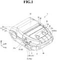
- FIG. 1 is a perspective view of a portable printer 1, for illustrating a state in which a paper cover 12 takes a closed position.
- FIG. 2 is a perspective view of the portable printer 1, for illustrating a state in which the paper cover 12 takes an opened position.
- the arrow FR in the drawings represents a forward direction
- the arrow LH represents a leftward direction
- the arrow UP represents an upward direction.
- the portable printer 1 of this embodiment is configured so as to be portable by a user.
- the portable printer 1 is configured to output (print) information, which is input to a host device (not shown), on a recording paper P (heat-sensitive paper) by communicating with the host device.
- the portable printer 1 has a structure in which a printer module 2 (see FIG. 2 ), a battery 3, a control unit 4, or other components are accommodated in a casing 5.
- the casing 5 includes a casing main body 11 and the paper cover 12.
- the casing main body 11 and the paper cover 12 are made of a resin material (for example, polycarbonate).
- the casing main body 11 is formed of an upper case 14 and a lower case 15 that are coupled in a vertical direction.
- the casing main body 11 has a component accommodating portion 21 positioned in a front portion of the casing main body 11, and a roll sheet receiving portion 22 positioned in a rear portion of the casing main body 11.
- the component accommodating portion 21 is formed into a box shape opening rearward.
- Functional portions 23 to 25, which are configured to perform various operations of the portable printer 1, are arranged on an upper wall 21a of the component accommodating portion 21 (casing main body 11).
- the functional portions 23 to 25 include various function switches 23 (for example, power switch and Feed switch), display windows 24 configured to display states of the portable printer 1 (for example, power ON/OFF state and presence/absence of error), and an open button 25.
- function switches 23 for example, power switch and Feed switch
- display windows 24 configured to display states of the portable printer 1 (for example, power ON/OFF state and presence/absence of error)
- an open button 25 In the illustrated example, two function switches 23 are arranged side by side in a lateral direction. Further, on the upper wall 21a of the component accommodating portion 21, two display windows 24 are arranged side by side in the lateral direction at portions positioned rearward with respect to the function switches 23.
- the open button 25 is arranged at a left side portion of the component accommodating portion 21 (corner
- the connector opening 31 is formed into a rectangular shape when viewed from the side in the lateral direction.
- the connector opening 31 is defined by a mating surface between the upper case 14 and the lower case 15.
- the connector opening 31 is defined by an inner peripheral surface of a cutout portion 32 formed in the upper case 14 and an upper end surface of the lower case 15.
- the connector opening 31 may be formed only in the upper case 14, or may be formed only in the lower case 15.
- the roll sheet receiving portion 22 is formed into a box shape opening upward.
- the roll sheet receiving portion 22 is continuous with a rear end portion of the component accommodating portion 21.
- a roll sheet R is put into the roll sheet receiving portion 22 from above.
- the roll sheet R of this embodiment is formed by rolling up the recording paper P.
- the paper cover 12 is rotatably coupled to a rear end portion of the roll sheet receiving portion 22 (casing main body 11).
- the paper cover 12 is configured to open or close the roll sheet receiving portion 22 along with rotary operations.
- a gap which is formed between a front end edge of the paper cover 12 and a rear end edge of the upper wall 21a of the component accommodating portion 21, serves as a discharge port 33 configured to discharge the recording paper P.
- a cutting blade 35 configured to cut the recording paper P discharged through the discharge port 33.
- the printer module 2 includes a head unit 41 having a thermal head, and a platen roller 42.
- the printer module 2 is configured to perform printing on the recording paper P by heating the recording paper P through use of the thermal head (not shown) under a state in which the recording paper P is nipped between the platen roller 42 and the thermal head. In this manner, a printed surface of the recording paper P is colored.
- the head unit 41 is accommodated in a rear portion of the component accommodating portion 21. Specifically, the head unit 41 is assembled to the component accommodating portion 21 so that the thermal head faces an inside of the roll sheet receiving portion 22 from the front.
- the platen roller 42 is arranged at a front end portion of a lower surface of the paper cover 12. As illustrated in FIG. 2 , a platen support portion 43 is formed at the front end portion of the lower surface of the paper cover 12. The platen roller 42 is supported by the platen support portion 43 in a rotatable manner about an axis extending in the lateral direction. Further, the platen roller 42 is configured so as to be removably mountable to the head unit 41 along with opening and closing operations of the paper cover 12. That is, the platen roller 42 is coupled to the head unit 41 at the closed position of the paper cover 12. Meanwhile, through the pressing operation of the above-mentioned open button 25, an engagement between the head unit 41 and the platen roller 42 is released so that the paper cover 12 takes an opened position.
- the battery 3 is accommodated in a lower portion of the component accommodating portion 21.
- the battery 3 is configured to supply electric power to the printer module 2 or other components through the control unit 4. Further, the battery 3 is charged by an external power supply (not shown) through a female-side connector 75, or a charging terminal 45 arranged at a front end portion of the component accommodating portion 21, which are described later.
- the charging terminal 45 is partially exposed to an outside from the front end portion of the component accommodating portion 21, and is connectable to an external terminal (not shown) of a cradle.
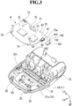
- FIG. 3 is an exploded perspective view for illustrating the control unit 4 and the upper case 14. As illustrated in FIG. 1 and FIG. 3 , the control unit 4 is accommodated above the above-mentioned battery 3 in a front portion of the component accommodating portion 21.
- the control unit 4 has various electronic components mounted on a control board 51, which has wiring patterns (not shown) formed thereon.
- the control board 51 is arranged in the component accommodating portion 21 under a state in which the vertical direction matches with a thickness direction of the control board 51.
- the control board 51 is fixed to board support portions 52 formed in the upper case 14 with screws and the like.
- the control board 51 is fixed to the upper case 14 so that a lower surface of the control board 51 is positioned above a lower surface of the upper case 14.
- the control board 51 may be fixed to the lower case 15.
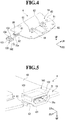
- FIG. 4 is a perspective view for illustrating the control unit 4 when viewed from above.
- switching elements 61 on an upper surface of the control board 51, switching elements 61, LEDs 62, and a Bluetooth (registered trademark) module 63 are mounted, for example.
- the switching elements 61 are respectively arranged at positions of the control board 51, which overlap with the above-mentioned function switches 23 (see FIG. 1 ) when viewed from the vertical direction. That is, the switching elements 61 are operable in response to pressing operation of each of the function switches 23.
- the LEDs 62 are respectively arranged at positions of the control board 51, which overlap with the above-mentioned display windows 24 (see FIG. 1 ) when viewed from the vertical direction.
- Light beams emitted from the LEDs 62 are propagated in light-guiding members 65 (see FIG. 3 ) which are arranged between the respective LEDs 62 and the upper wall 21a of the component accommodating portion 21. Then, the light beams exit to an outside of the casing 5 through the display windows 24.
- the Bluetooth (registered trademark) module 63 is configured to perform wireless communication between the portable printer 1 and the host device.
- a printer adapter 71 As illustrated in FIG. 3 , on the lower surface of the control board 51, a printer adapter 71, a battery adapter 72, a driver IC 73, charging electrodes 74, the female-side connector 75, and other components are mounted.
- the printer adapter 71 is mounted to a rear end portion of the control board 51.
- a printer wire (not shown) which is drawn out from the printer module 2 (thermal head) is connected to the printer adapter 71.
- the battery adapter 72 is mounted to the rear end portion of the control board 51 on the left with respect to the printer adapter 71.
- a battery wire (not shown) which is drawn out from the battery 3 (see FIG. 1 ) is connected to the battery adapter 72.
- the charging electrodes 74 are formed at a front end portion of the control board 51.
- the charging electrodes 74 are connected to the above-mentioned charging terminal 45 (see FIG. 1 ) in the component accommodating portion 21, and to the battery adapter 72 and other components through the wiring patterns (not shown). It is possible to appropriately change a type, a layout, and other factors of the electronic components mounted to the control board 51.
- FIG. 5 is a perspective view for illustrating a periphery of the female-side connector 75 of the control unit 4.
- FIG. 6 is a sectional view taken along the line VI-VI of FIG. 1 .
- FIG. 7 is a sectional view taken along the line VII-VII of FIG. 1 .
- the female-side connector 75 is mounted to a right-side end portion of the lower surface of the control board 51.
- a USB (micro-B) connector is used as the female-side connector 75, for example.
- the female-side connector 75 is mounted to the control board 51 under a state in which an opening 75a is oriented rightward.
- a right-side end portion of the female-side connector 75 protrudes rightward with respect to the control board 51.
- the right-side end portion of the female-side connector 75 enters the above-mentioned connector opening 31 from the left.
- FIG. 8 is an enlarged side view of the portable printer 1 when viewed from the right side.
- the female-side connector 75 is exposed to the outside of the casing 5 through the above-mentioned connector opening 31.
- the female-side connector 75 is configured so that the male-side connector (not shown) is removably mountable through the connector opening 31.
- the female-side connector 75 is used for, for example, wired communication between the portable printer 1 and the host device, or charging from the external power supply.
- slits 81 are respectively formed at portions which are positioned on both front and rear sides of the control board 51 with respect to the portion to which the female-side connector 75 is mounted. Each of the slits 81 passes through the control board 51 in the vertical direction, and extends in the lateral direction. Each of the slits 81 is opened in a right-side end surface of the control board 51.
- control board 51 of this embodiment is divided into a connector mounting portion 82 to which, among the above-mentioned electronic components, the female-side connector 75 is mounted, and a main body mounting portion 83 to which the electronic components other than the female-side connector 75 (for example, switching elements 61, LEDs 62, and charging electrodes 74) are mounted.
- the connector mounting portion 82 can be bendingly deformable while protruding rightward from the main body mounting portion 83 in a cantilever manner. Therefore, the female-side connector 75 is elastically supported by the control board 51 through intermediation of the connector mounting portion 82.
- a right-side end surface of the connector mounting portion 82 slightly protrudes rightward with respect to a right-side end surface of the main body mounting portion 83.
- the right-side end surface of the connector mounting portion 82 may be flush with the right-side end surface of the main body mounting portion 83, or may be arranged leftward with respect to the right-side end surface of the main body mounting portion 83.
- a connector cover 100 is mounted to the female-side connector 75.
- the connector cover 100 is made of an elastically deformable material (for example, polyurethane or rubber).
- the connector cover 100 is formed into a box shape opening upward and rightward.
- the above-mentioned connector cover 100 includes a buffer portion 101 fitted onto the right-side end portion of the female-side connector 75.
- the buffer portion 101 is formed into a rectangular frame shape. That is, the buffer portion 101 circumferentially surrounds a periphery of the right-side end portion of the female-side connector 75. When viewed from the side in the lateral direction, an inner dimension of the buffer portion 101 is smaller than an outer dimension of the female-side connector 75. Specifically, it is preferred that the buffer portion 101 secure an interference between the buffer portion 101 and the female-side connector 75. With this structure, the buffer portion 101 is fitted onto the female-side connector 75 under a state of being elastically deformed.
- the buffer portion 101 is interposed between an outer peripheral surface of the female-side connector 75 and an inner peripheral surface of the connector opening 31 (upper end surface of lower case 15 and inner peripheral surface of cutout portion 32).
- the buffer portion 101 is fitted into the connector opening 31.
- the female-side connector 75 and the buffer portion 101 are exposed to the outside of the casing 5 through the connector opening 31.
- an outer dimension of the buffer portion 101 is larger than an inner dimension of the connector opening 31. That is, it is preferred that the buffer portion 101 secure an interference between the buffer portion 101 and the connector opening 31.
- the buffer portion 101 is fitted into the connector opening 31 under the state of being elastically deformed.
- the above-mentioned buffer portion 101 is arranged between the outer peripheral surface of the female-side connector 75 and the inner peripheral surface of the connector opening 31 along an entire circumference of the female-side connector 75 without any gap. Further, it is preferred that a right-side end surface of the buffer portion 101 be arranged at the same position as a right end edge of the female-side connector 75, or on the left with respect to the female-side connector 75. With this structure, when the connectors are mounted, an interference between the buffer portion 101 and the male-side connector can be prevented.
- the connector cover 100 includes a connection portion 102 extending leftward from the buffer portion 101.
- the connection portion 102 is formed integrally with the buffer portion 101.
- the connection portion 102 surrounds a lower surface and both front and rear surfaces of the female-side connector 75.
- the connector cover 100 includes a regulation portion 103 continuous with a left-side end portion of the connection portion 102.
- the regulation portion 103 is formed integrally with the connection portion 102 and the buffer portion 101.
- the regulation portion 103 covers a left-side end surface of the female-side connector 75 from the left. That is, the regulation portion 103 is engaged with (held in abutment against) the left-side end surface of the female-side connector 75 from the left.
- the regulation portion 103 regulates a movement of the connector cover 100 to the right with respect to the female-side connector 75 (movement to outside of casing 5 through connector opening 31).
- the regulation portion 103 may be away from the left-side end surface of the female-side connector 75.
- upper end surfaces of the connection portion 102 and the regulation portion 103 are close to or held in abutment against the control board 51 (connector mounting portion 82) from the lower side.
- a part defined by an upper portion of the buffer portion 101, and upper end portions of the connection portion 102 and the regulation portion 103 form a mounting opening 104 opening upward.
- the female-side connector 75 is caused to enter the connector cover 100 from the lower side through the mounting opening 104, while fitting the female-side connector 75 into the buffer portion 101 from the left. In this manner, as described above, the connector cover 100 is mounted to the female-side connector 75.
- the connector cover 100 (buffer portion 101) is interposed between the inner peripheral surface of the connector opening 31 and the outer peripheral surface of the female-side connector 75.
- the female-side connector 75 can be prevented from shifting along with, for example, twisting of the male-side connector.
- a twisting force generated when mounting or removing the male-side connector can be reduced, thereby being capable of reducing a twisting force transmitted to a mounting portion between the female-side connector 75 and the control board 51.
- the connector cover 100 is interposed between the inner peripheral surface of the connector opening 31 and the outer peripheral surface of the female-side connector 75, thereby being capable of alleviating a drop impact input to the casing 5 by the connector cover 100.
- the drop impact can be prevented from being transmitted to the mounting portion. Accordingly, in the portable printer 1 of this embodiment, there can be reduced, among external forces transmitted to the mounting portion, both external forces of an external force directly acting on the female-side connector 75 (for example, twisting force) and an external force acting through intermediation of the casing 5 (for example, drop impact). As a result, for example, separation of the female-side connector 75 from the control board 51 is prevented, thereby being capable of enhancing durability and reliability of the portable printer 1.
- the connector cover 100 is made of the elastically deformable material so that the shift amount can be absorbed by the elastic deformation of the connector cover 100, even when the position of the female-side connector 75 with respect to the connector opening 31 is shifted from a desired position due to tolerance. Accordingly, the control board 51 can be arranged in the casing 5 without considering a positional accuracy of the female-side connector 75. Therefore, the other electronic components mounted to the control board 51 can be arranged in the casing 5 at a higher accuracy as compared to a case in which the control board 51 is mounted to the casing 5 with reference to the female-side connector 75.
- the female-side connector 75 and the other electronic components can be mounted to a single control board 51, thereby being capable of achieving downsizing and cost reduction of the control board 51. Therefore, the downsized and low-cost portable printer 1 can be provided.
- the connector cover 100 is arranged in the connector opening 31 under the state of being elastically deformed. Therefore, the connector cover 100 can be arranged between the inner peripheral surface of the connector opening 31 and the outer peripheral surface of the female-side connector 75 without any gap. With this structure, both the twisting force and the drop impact, which act on the mounting portion, can reliably be reduced. Further, it is possible to prevent dust and liquid from entering the casing 5 through a gap between the inner peripheral surface of the connector opening 31 and the outer peripheral surface of the female-side connector 75. At the same time, it is possible to prevent static electricity or noise from transmitting to the control board 51 through the above-mentioned gap. As a result, the reliability of the portable printer 1 can be enhanced more.
- the connector cover 100 of this embodiment includes the regulation portion 103 for regulating the movement of the connector cover 100 to the outside of the casing 5 through the connector opening 31.
- the connector cover 100 can be prevented from falling off from the female-side connector 75.
- the control board 51 includes the connector mounting portion 82 for elastically supporting the female-side connector 75.
- the connector mounting portion 82 is bendingly deformed.
- the part of the control board 51 positioned between a pair of the slits 81 forms the connector mounting portion 82.
- the control board 51 can be downsized.
- the casing main body 11 component accommodating portion 21
- the portable printer 1 can further be downsized.
- cooperative electronic components switching elements 61, LEDs 62, and charging electrodes 74
- the functional portions for example, function switches 23, display windows 24, and charging terminal 45
- the other electronic components which are mounted to a single control board 51 together with the female-side connector 75, in the casing 5 at a high accuracy without considering the positional tolerance of the female-side connector 75 in this embodiment. Therefore, positional shift between the cooperative electronic components and the functional portions can be suppressed. As a result, excellent operability (for example, pressing operability or visibility) can be provided to the functional portions.
- the thermal printer is used as the printer module 2.
- the present invention is not limited to the structure, and various printer modules (for example, dot impact type) can be used.
- description is made of the structure in which the USB connector is used as the female-side connector 75.
- the present invention is not limited to the structure, and the female-side connector having various standards (for example, serial connector) can be used.
- an outer shape of the female-side connector 75 is not limited to a rectangular shape.
- the present invention is not limited to the structure.
- the connector cover only needs to be interposed at least between the inner peripheral surface of the connector opening 31 and the outer peripheral surface of the female-side connector 75 (part corresponding to buffer portion 101).
- description is made of the structure in which the regulation portion 103 is engaged with the left-side end surface of the female-side connector 75.
- the regulation portion may be formed at any position and into any shapes as long as the regulation portion regulates the movement of the connector cover to the outside of the casing 5 through the connector opening 31.
- the present invention is not limited to the structure, and the connector mounting portion 82 may protrude with respect to the right-side end surface of the main body mounting portion 83.
Landscapes
- Engineering & Computer Science (AREA)
- Computer Networks & Wireless Communication (AREA)
- Accessory Devices And Overall Control Thereof (AREA)
- Printers Characterized By Their Purpose (AREA)
- Electrophotography Configuration And Component (AREA)
Abstract
Description
- The present invention relates to a portable printer.
- There have been known portable printers configured to output (print) information, which is input to a host device (for example, personal digital assistant (PDA)), at visiting places or the like. The portable printer of this type includes a casing in which a printer module is accommodated, and a control board accommodated in the casing and connected to the printer module.
- Among the above-mentioned portable printers, there is a portable printer to which a female-side connector for USB is provided. The female-side connector is mounted to the control board, and is exposed to an outside of the casing through a connector opening formed in the casing. A male-side connector (USB terminal) is mounted to the female-side connector at the time of, for example, communication between the portable printer and the host device, or charging of the portable printer.
- Incidentally, the above-mentioned female-side connector may be supported by the control board under a state of being away from the casing (for example, inner peripheral surface of connector opening) in some cases. In this case, at the time of, for example, mounting or removing the male-side connector, an external force generated by twisting the male-side connector (hereinafter simply referred to as "twisting force") is liable to be transmitted to a mounting portion between the female-side connector and the control board.
- Meanwhile, the female-side connector may also be fixed to the casing (inner peripheral surface of connector opening) so that the above-mentioned twisting force is prevented from being transmitted to the mounting portion. However, there is a disadvantage in that fixing the female-side connector to the casing causes the external force such as a drop impact, which is generated when the portable printer falls to be transmitted to the mounting portion through intermediation of the casing. Therefore, in the related-art portable printer, among the external forces transmitted to the mounting portion, it is difficult to reduce both the external forces of an external force directly acting on the female-side connector (for example, twisting force) and an external force acting through intermediation of the casing (for example, drop impact). Thus, there is a risk in that, for example, the female-side connector is separated from the control board. Accordingly, there still remains room for improvement of durability and reliability of the portable printer.
- Further, when the female-side connector is fixed to the casing, there is a need to position the female-side connector and the casing at a high accuracy. However, when tolerance (for example, mounting tolerance of female-side connector to control board, dimensional tolerance of casing, control board, or other components, or coupling tolerance of the casing with the control board) is considered, there is a problem in that it is difficult to arrange the female-side connector at a desired position of the casing. In particular, in recent years, in order to achieve downsizing or lower cost, there is a case in which other electronic components such as LEDs and switching elements are collectively mounted on a single control board in addition to the female-side connector. In this case, when the control board is coupled to the casing with reference to the above-mentioned other electronic components, it is difficult to align the female-side connector and the connector opening, and there is a risk in that the female-side connector cannot be arranged at the desired position of the casing. Meanwhile, when the control board is coupled to the casing with reference to the female-side connector, there is a risk in that the other electronic components cannot be arranged at the desired position of the casing.
- Further, when the female-side connector is away from the casing, and further a guide member configured to guide a mold part of the male-side connector and a cable of the male-side connector is arranged in the casing, it is conceivable that both the twisting force and the drop impact, which act on the mounting portion, can be reduced. However, the above-mentioned mold part and cable are not standardized, and hence it is difficult to form the guide member in conformity to various shapes. Moreover, there is a problem in that designability is lowered through provision of the guide member to the casing.
- In view of the above-mentioned circumstances, in the portable printer of this type, it has been demanded that the durability and reliability be enhanced at the same time of achieving the simplification and the suppression of the lowering of the designability.
- According to one embodiment of the present invention, there is provided a portable printer, including: a casing accommodating a printer module; a control board accommodated in the casing and electrically connected to the printer module; a female-side connector mounted on the control board and exposed to an outside of the casing through a connector opening formed in the casing, the female-side connector detachably mounting a male-side connector; and an elastic member interposed between an inner peripheral surface of the connector opening and an outer peripheral surface of the female-side connector.
- In the above-mentioned portable printer according to the one embodiment of the present invention, the elastic member is interposed between the inner peripheral surface of the connector opening and the outer peripheral surface of the female-side connector along an entire circumference of the female-side connector.
- In the above-mentioned portable printer according to the one embodiment of the present invention, an outer dimension of the elastic member, when a part of the elastic member being positioned in the connector opening is viewed in an opening direction of the connector opening, is larger than an inner dimension of the connector opening when the connector opening is viewed in the opening direction, and wherein the elastic member is arranged in the connector opening under a state of being elastically deformed.
- In the above-mentioned portable printer according to the one embodiment of the present invention, the elastic member includes a buffer portion arranged between the inner peripheral surface of the connector opening and the outer peripheral surface of the female-side connector; and a regulation portion engaged with the female-side connector, the regulation portion regulating a movement of the elastic member to the outside of the casing through the connector opening with respect to the female-side connector.
- In the above-mentioned portable printer according to the one embodiment of the present invention, a part of the control board, to which the female-side connector is mounted, constitutes a connector mounting portion configured to elastically support the female-side connector.
- In the above-mentioned portable printer according to the one embodiment of the present invention, the control board includes a pair of slits formed therein, and wherein a part of the control board, which is positioned between the pair of slits, constitutes the connector mounting portion.
- In the above-mentioned portable printer according to the one embodiment of the present invention, the control board includes an electronic component, which is cooperative with a functional portion exposed to an outer surface of the casing.
- Embodiments of the present invention will now be described by way of further example only and with reference to the accompanying drawings, in which:
-
FIG. 1 is a perspective view of a portable printer according to an embodiment of the present invention, for illustrating a state in which a paper cover takes a closed position. -
FIG. 2 is a perspective view of the portable printer according to the embodiment, for illustrating a state in which the paper cover takes an opened position. -
FIG. 3 is an exploded perspective view for illustrating a control unit and an upper case of the portable printer according to the embodiment. -
FIG. 4 is a perspective view for illustrating the control unit of the portable printer according to the embodiment, when viewed from above. -
FIG. 5 is a perspective view for illustrating a periphery of a female-side connector of the control unit of the portable printer according to the embodiment. -
FIG. 6 is a sectional view taken along the line VI-VI ofFIG. 1 . -
FIG. 7 is a sectional view taken along the line VII-VII ofFIG. 1 . -
FIG. 8 is an enlarged side view of the portable printer according to the embodiment when viewed from the right side. -
FIG. 1 is a perspective view of aportable printer 1, for illustrating a state in which apaper cover 12 takes a closed position.FIG. 2 is a perspective view of theportable printer 1, for illustrating a state in which thepaper cover 12 takes an opened position. In the following description, for the sake of convenience, the arrow FR in the drawings represents a forward direction, the arrow LH represents a leftward direction, and the arrow UP represents an upward direction. As illustrated inFIG. 1 andFIG. 2 , theportable printer 1 of this embodiment is configured so as to be portable by a user. Theportable printer 1 is configured to output (print) information, which is input to a host device (not shown), on a recording paper P (heat-sensitive paper) by communicating with the host device. - The
portable printer 1 has a structure in which a printer module 2 (seeFIG. 2 ), abattery 3, acontrol unit 4, or other components are accommodated in acasing 5. - The
casing 5 includes a casingmain body 11 and thepaper cover 12. The casingmain body 11 and thepaper cover 12 are made of a resin material (for example, polycarbonate). The casingmain body 11 is formed of anupper case 14 and alower case 15 that are coupled in a vertical direction. The casingmain body 11 has acomponent accommodating portion 21 positioned in a front portion of the casingmain body 11, and a rollsheet receiving portion 22 positioned in a rear portion of the casingmain body 11. - The
component accommodating portion 21 is formed into a box shape opening rearward.Functional portions 23 to 25, which are configured to perform various operations of theportable printer 1, are arranged on anupper wall 21a of the component accommodating portion 21 (casing main body 11). Thefunctional portions 23 to 25 include various function switches 23 (for example, power switch and Feed switch), displaywindows 24 configured to display states of the portable printer 1 (for example, power ON/OFF state and presence/absence of error), and anopen button 25. In the illustrated example, twofunction switches 23 are arranged side by side in a lateral direction. Further, on theupper wall 21a of thecomponent accommodating portion 21, twodisplay windows 24 are arranged side by side in the lateral direction at portions positioned rearward with respect to thefunction switches 23. Theopen button 25 is arranged at a left side portion of the component accommodating portion 21 (corner portion formed betweenupper wall 21a andleft side wall 21b) so as to be pressable. - A connector opening 31, which passes through a
right side wall 21c in the lateral direction, is formed in theright side wall 21c of thecomponent accommodating portion 21. Theconnector opening 31 is formed into a rectangular shape when viewed from the side in the lateral direction. The connector opening 31 is defined by a mating surface between theupper case 14 and thelower case 15. Specifically, theconnector opening 31 is defined by an inner peripheral surface of acutout portion 32 formed in theupper case 14 and an upper end surface of thelower case 15. Theconnector opening 31 may be formed only in theupper case 14, or may be formed only in thelower case 15. - As illustrated in
FIG. 2 , the rollsheet receiving portion 22 is formed into a box shape opening upward. The rollsheet receiving portion 22 is continuous with a rear end portion of thecomponent accommodating portion 21. A roll sheet R is put into the rollsheet receiving portion 22 from above. The roll sheet R of this embodiment is formed by rolling up the recording paper P. - The
paper cover 12 is rotatably coupled to a rear end portion of the roll sheet receiving portion 22 (casing main body 11). Thepaper cover 12 is configured to open or close the rollsheet receiving portion 22 along with rotary operations. At a closed position of thepaper cover 12 illustrated inFIG. 1 , a gap, which is formed between a front end edge of thepaper cover 12 and a rear end edge of theupper wall 21a of thecomponent accommodating portion 21, serves as a discharge port 33 configured to discharge the recording paper P. At the rear end edge of theupper wall 21a, there is arranged acutting blade 35 configured to cut the recording paper P discharged through the discharge port 33. - As the
printer module 2, a thermal printer is used, for example. Theprinter module 2 includes ahead unit 41 having a thermal head, and aplaten roller 42. Theprinter module 2 is configured to perform printing on the recording paper P by heating the recording paper P through use of the thermal head (not shown) under a state in which the recording paper P is nipped between theplaten roller 42 and the thermal head. In this manner, a printed surface of the recording paper P is colored. - The
head unit 41 is accommodated in a rear portion of thecomponent accommodating portion 21. Specifically, thehead unit 41 is assembled to thecomponent accommodating portion 21 so that the thermal head faces an inside of the rollsheet receiving portion 22 from the front. - The
platen roller 42 is arranged at a front end portion of a lower surface of thepaper cover 12. As illustrated inFIG. 2 , aplaten support portion 43 is formed at the front end portion of the lower surface of thepaper cover 12. Theplaten roller 42 is supported by theplaten support portion 43 in a rotatable manner about an axis extending in the lateral direction. Further, theplaten roller 42 is configured so as to be removably mountable to thehead unit 41 along with opening and closing operations of thepaper cover 12. That is, theplaten roller 42 is coupled to thehead unit 41 at the closed position of thepaper cover 12. Meanwhile, through the pressing operation of the above-mentionedopen button 25, an engagement between thehead unit 41 and theplaten roller 42 is released so that thepaper cover 12 takes an opened position. - The
battery 3 is accommodated in a lower portion of thecomponent accommodating portion 21. Thebattery 3 is configured to supply electric power to theprinter module 2 or other components through thecontrol unit 4. Further, thebattery 3 is charged by an external power supply (not shown) through a female-side connector 75, or a chargingterminal 45 arranged at a front end portion of thecomponent accommodating portion 21, which are described later. The chargingterminal 45 is partially exposed to an outside from the front end portion of thecomponent accommodating portion 21, and is connectable to an external terminal (not shown) of a cradle. -
FIG. 3 is an exploded perspective view for illustrating thecontrol unit 4 and theupper case 14. As illustrated inFIG. 1 andFIG. 3 , thecontrol unit 4 is accommodated above the above-mentionedbattery 3 in a front portion of thecomponent accommodating portion 21. Thecontrol unit 4 has various electronic components mounted on acontrol board 51, which has wiring patterns (not shown) formed thereon. - As illustrated in
FIG. 3 , thecontrol board 51 is arranged in thecomponent accommodating portion 21 under a state in which the vertical direction matches with a thickness direction of thecontrol board 51. Specifically, thecontrol board 51 is fixed toboard support portions 52 formed in theupper case 14 with screws and the like. In the illustrated example, thecontrol board 51 is fixed to theupper case 14 so that a lower surface of thecontrol board 51 is positioned above a lower surface of theupper case 14. Thecontrol board 51 may be fixed to thelower case 15. -
FIG. 4 is a perspective view for illustrating thecontrol unit 4 when viewed from above. As illustrated inFIG. 4 , on an upper surface of thecontrol board 51, switchingelements 61,LEDs 62, and a Bluetooth (registered trademark)module 63 are mounted, for example. The switchingelements 61 are respectively arranged at positions of thecontrol board 51, which overlap with the above-mentioned function switches 23 (seeFIG. 1 ) when viewed from the vertical direction. That is, the switchingelements 61 are operable in response to pressing operation of each of the function switches 23. - The
LEDs 62 are respectively arranged at positions of thecontrol board 51, which overlap with the above-mentioned display windows 24 (seeFIG. 1 ) when viewed from the vertical direction. Light beams emitted from theLEDs 62 are propagated in light-guiding members 65 (seeFIG. 3 ) which are arranged between therespective LEDs 62 and theupper wall 21a of thecomponent accommodating portion 21. Then, the light beams exit to an outside of thecasing 5 through thedisplay windows 24. The Bluetooth (registered trademark)module 63 is configured to perform wireless communication between theportable printer 1 and the host device. - As illustrated in
FIG. 3 , on the lower surface of thecontrol board 51, aprinter adapter 71, abattery adapter 72, adriver IC 73, chargingelectrodes 74, the female-side connector 75, and other components are mounted. Theprinter adapter 71 is mounted to a rear end portion of thecontrol board 51. A printer wire (not shown) which is drawn out from the printer module 2 (thermal head) is connected to theprinter adapter 71. Thebattery adapter 72 is mounted to the rear end portion of thecontrol board 51 on the left with respect to theprinter adapter 71. A battery wire (not shown) which is drawn out from the battery 3 (seeFIG. 1 ) is connected to thebattery adapter 72. The chargingelectrodes 74 are formed at a front end portion of thecontrol board 51. The chargingelectrodes 74 are connected to the above-mentioned charging terminal 45 (seeFIG. 1 ) in thecomponent accommodating portion 21, and to thebattery adapter 72 and other components through the wiring patterns (not shown). It is possible to appropriately change a type, a layout, and other factors of the electronic components mounted to thecontrol board 51. -
FIG. 5 is a perspective view for illustrating a periphery of the female-side connector 75 of thecontrol unit 4.FIG. 6 is a sectional view taken along the line VI-VI ofFIG. 1 .FIG. 7 is a sectional view taken along the line VII-VII ofFIG. 1 . As illustrated inFIG. 5 to FIG. 7 , the female-side connector 75 is mounted to a right-side end portion of the lower surface of thecontrol board 51. A USB (micro-B) connector is used as the female-side connector 75, for example. The female-side connector 75 is mounted to thecontrol board 51 under a state in which anopening 75a is oriented rightward. A right-side end portion of the female-side connector 75 protrudes rightward with respect to thecontrol board 51. The right-side end portion of the female-side connector 75 enters the above-mentionedconnector opening 31 from the left. -
FIG. 8 is an enlarged side view of theportable printer 1 when viewed from the right side. As illustrated inFIG. 6 to FIG. 8 , the female-side connector 75 is exposed to the outside of thecasing 5 through the above-mentionedconnector opening 31. The female-side connector 75 is configured so that the male-side connector (not shown) is removably mountable through theconnector opening 31. In this embodiment, the female-side connector 75 is used for, for example, wired communication between theportable printer 1 and the host device, or charging from the external power supply. - As illustrated in
FIG. 3 andFIG. 4 , slits 81 are respectively formed at portions which are positioned on both front and rear sides of thecontrol board 51 with respect to the portion to which the female-side connector 75 is mounted. Each of theslits 81 passes through thecontrol board 51 in the vertical direction, and extends in the lateral direction. Each of theslits 81 is opened in a right-side end surface of thecontrol board 51. - Further, the
control board 51 of this embodiment is divided into aconnector mounting portion 82 to which, among the above-mentioned electronic components, the female-side connector 75 is mounted, and a mainbody mounting portion 83 to which the electronic components other than the female-side connector 75 (for example, switchingelements 61,LEDs 62, and charging electrodes 74) are mounted. In this case, theconnector mounting portion 82 can be bendingly deformable while protruding rightward from the mainbody mounting portion 83 in a cantilever manner. Therefore, the female-side connector 75 is elastically supported by thecontrol board 51 through intermediation of theconnector mounting portion 82. In the illustrated example, a right-side end surface of theconnector mounting portion 82 slightly protrudes rightward with respect to a right-side end surface of the mainbody mounting portion 83. The right-side end surface of theconnector mounting portion 82 may be flush with the right-side end surface of the mainbody mounting portion 83, or may be arranged leftward with respect to the right-side end surface of the mainbody mounting portion 83. - As illustrated in
FIG. 4 and FIG. 5 , aconnector cover 100 is mounted to the female-side connector 75. Theconnector cover 100 is made of an elastically deformable material (for example, polyurethane or rubber). Theconnector cover 100 is formed into a box shape opening upward and rightward. - Specifically, the above-mentioned
connector cover 100 includes abuffer portion 101 fitted onto the right-side end portion of the female-side connector 75. Thebuffer portion 101 is formed into a rectangular frame shape. That is, thebuffer portion 101 circumferentially surrounds a periphery of the right-side end portion of the female-side connector 75. When viewed from the side in the lateral direction, an inner dimension of thebuffer portion 101 is smaller than an outer dimension of the female-side connector 75. Specifically, it is preferred that thebuffer portion 101 secure an interference between thebuffer portion 101 and the female-side connector 75. With this structure, thebuffer portion 101 is fitted onto the female-side connector 75 under a state of being elastically deformed. - As illustrated in
FIG. 6 to FIG. 8 , in the above-mentionedconnector opening 31, thebuffer portion 101 is interposed between an outer peripheral surface of the female-side connector 75 and an inner peripheral surface of the connector opening 31 (upper end surface oflower case 15 and inner peripheral surface of cutout portion 32). In this embodiment, thebuffer portion 101 is fitted into theconnector opening 31. With this structure, the female-side connector 75 and thebuffer portion 101 are exposed to the outside of thecasing 5 through theconnector opening 31. When viewed from the side in the lateral direction, an outer dimension of thebuffer portion 101 is larger than an inner dimension of theconnector opening 31. That is, it is preferred that thebuffer portion 101 secure an interference between thebuffer portion 101 and theconnector opening 31. With this structure, thebuffer portion 101 is fitted into theconnector opening 31 under the state of being elastically deformed. - The above-mentioned
buffer portion 101 is arranged between the outer peripheral surface of the female-side connector 75 and the inner peripheral surface of theconnector opening 31 along an entire circumference of the female-side connector 75 without any gap. Further, it is preferred that a right-side end surface of thebuffer portion 101 be arranged at the same position as a right end edge of the female-side connector 75, or on the left with respect to the female-side connector 75. With this structure, when the connectors are mounted, an interference between thebuffer portion 101 and the male-side connector can be prevented. - As illustrated in
FIG. 4 and FIG. 5 , theconnector cover 100 includes aconnection portion 102 extending leftward from thebuffer portion 101. Theconnection portion 102 is formed integrally with thebuffer portion 101. Theconnection portion 102 surrounds a lower surface and both front and rear surfaces of the female-side connector 75. - As illustrated in
FIG. 6 andFIG. 7 , theconnector cover 100 includes aregulation portion 103 continuous with a left-side end portion of theconnection portion 102. Theregulation portion 103 is formed integrally with theconnection portion 102 and thebuffer portion 101. Theregulation portion 103 covers a left-side end surface of the female-side connector 75 from the left. That is, theregulation portion 103 is engaged with (held in abutment against) the left-side end surface of the female-side connector 75 from the left. Specifically, theregulation portion 103 regulates a movement of theconnector cover 100 to the right with respect to the female-side connector 75 (movement to outside ofcasing 5 through connector opening 31). However, theregulation portion 103 may be away from the left-side end surface of the female-side connector 75. Further, in the illustrated example, upper end surfaces of theconnection portion 102 and theregulation portion 103 are close to or held in abutment against the control board 51 (connector mounting portion 82) from the lower side. - As illustrated in
FIG. 4 andFIG. 6 , in theconnector cover 100, a part defined by an upper portion of thebuffer portion 101, and upper end portions of theconnection portion 102 and theregulation portion 103 form a mountingopening 104 opening upward. In this embodiment, in order to mount theconnector cover 100 to the female-side connector 75, for example, the female-side connector 75 is caused to enter theconnector cover 100 from the lower side through the mountingopening 104, while fitting the female-side connector 75 into thebuffer portion 101 from the left. In this manner, as described above, theconnector cover 100 is mounted to the female-side connector 75. - As described above, in this embodiment, the connector cover 100 (buffer portion 101) is interposed between the inner peripheral surface of the
connector opening 31 and the outer peripheral surface of the female-side connector 75. According to this structure, the female-side connector 75 can be prevented from shifting along with, for example, twisting of the male-side connector. Thus, a twisting force generated when mounting or removing the male-side connector can be reduced, thereby being capable of reducing a twisting force transmitted to a mounting portion between the female-side connector 75 and thecontrol board 51. Further, theconnector cover 100 is interposed between the inner peripheral surface of theconnector opening 31 and the outer peripheral surface of the female-side connector 75, thereby being capable of alleviating a drop impact input to thecasing 5 by theconnector cover 100. In this manner, the drop impact can be prevented from being transmitted to the mounting portion. Accordingly, in theportable printer 1 of this embodiment, there can be reduced, among external forces transmitted to the mounting portion, both external forces of an external force directly acting on the female-side connector 75 (for example, twisting force) and an external force acting through intermediation of the casing 5 (for example, drop impact). As a result, for example, separation of the female-side connector 75 from thecontrol board 51 is prevented, thereby being capable of enhancing durability and reliability of theportable printer 1. - Moreover, the
connector cover 100 is made of the elastically deformable material so that the shift amount can be absorbed by the elastic deformation of theconnector cover 100, even when the position of the female-side connector 75 with respect to theconnector opening 31 is shifted from a desired position due to tolerance. Accordingly, thecontrol board 51 can be arranged in thecasing 5 without considering a positional accuracy of the female-side connector 75. Therefore, the other electronic components mounted to thecontrol board 51 can be arranged in thecasing 5 at a higher accuracy as compared to a case in which thecontrol board 51 is mounted to thecasing 5 with reference to the female-side connector 75. In this case, in order to secure the positional accuracy of the female-side connector 75 with respect to theconnector opening 31, there is no need to separate a board to which the female-side connector 75 is mounted and a board to which the other electronic components are mounted. That is, the female-side connector 75 and the other electronic components can be mounted to asingle control board 51, thereby being capable of achieving downsizing and cost reduction of thecontrol board 51. Therefore, the downsized and low-costportable printer 1 can be provided. - Further, in order to reduce both the twisting force and the drop impact, which act on the mounting portion, there is no need to arrange a guide member for the male-side connector in the
casing 5, thereby being capable of suppressing lowering of the designability and complication of the structure. As described above, in theportable printer 1 of this embodiment, it is possible to suppress the lowering of the designability, achieve simplification, and enhance the durability and reliability. - In this embodiment, it is possible to reliably suppress both the twisting force and drop impact, which act on the mounting portion, because the connector cover 100 (buffer portion 101) is interposed between the inner peripheral surface of the
connector opening 31 and the outer peripheral surface of the female-side connector 75 along the entire circumference of the female-side connector 75. - In this embodiment, the
connector cover 100 is arranged in theconnector opening 31 under the state of being elastically deformed. Therefore, theconnector cover 100 can be arranged between the inner peripheral surface of theconnector opening 31 and the outer peripheral surface of the female-side connector 75 without any gap. With this structure, both the twisting force and the drop impact, which act on the mounting portion, can reliably be reduced. Further, it is possible to prevent dust and liquid from entering thecasing 5 through a gap between the inner peripheral surface of theconnector opening 31 and the outer peripheral surface of the female-side connector 75. At the same time, it is possible to prevent static electricity or noise from transmitting to thecontrol board 51 through the above-mentioned gap. As a result, the reliability of theportable printer 1 can be enhanced more. - The
connector cover 100 of this embodiment includes theregulation portion 103 for regulating the movement of theconnector cover 100 to the outside of thecasing 5 through theconnector opening 31. Thus, theconnector cover 100 can be prevented from falling off from the female-side connector 75. - In this embodiment, the
control board 51 includes theconnector mounting portion 82 for elastically supporting the female-side connector 75. Thus, when the twisting force and the drop impact are input to the female-side connector 75, theconnector mounting portion 82 is bendingly deformed. With this structure, the twisting force and the drop impact, which act in a thickness direction of the mounting portion (vertical direction), can more effectively be reduced. - In this embodiment, the part of the
control board 51 positioned between a pair of theslits 81 forms theconnector mounting portion 82. Thus, as compared to a case in which theconnector mounting portion 82 protrudes with respect to an outer peripheral edge of the mainbody mounting portion 83, thecontrol board 51 can be downsized. In this case, in the casing main body 11 (component accommodating portion 21), it is possible to prevent a dead space from being formed at a part which is positioned on both front and rear sides of theconnector mounting portion 82. As a result, theportable printer 1 can further be downsized. - In this embodiment, cooperative electronic components (switching
elements 61,LEDs 62, and charging electrodes 74), which are cooperative with the functional portions (for example, function switches 23,display windows 24, and charging terminal 45) exposed to an outer surface of thecasing 5, are mounted to asingle control board 51 together with the female-side connector 75. According to this structure, as described above, it is possible to arrange the other electronic components, which are mounted to asingle control board 51 together with the female-side connector 75, in thecasing 5 at a high accuracy without considering the positional tolerance of the female-side connector 75 in this embodiment. Therefore, positional shift between the cooperative electronic components and the functional portions can be suppressed. As a result, excellent operability (for example, pressing operability or visibility) can be provided to the functional portions. - The technical scope of the present invention is not limited to the above-mentioned embodiment, but various modifications may be made without departing from the scope of the present invention as defined by the claims.
- In the above-mentioned embodiment, description is made of the structure in which the thermal printer is used as the
printer module 2. However, the present invention is not limited to the structure, and various printer modules (for example, dot impact type) can be used. In the above-mentioned embodiment, description is made of the structure in which the USB connector is used as the female-side connector 75. However, the present invention is not limited to the structure, and the female-side connector having various standards (for example, serial connector) can be used. Further, an outer shape of the female-side connector 75 is not limited to a rectangular shape. - In the above-mentioned embodiment, description is made of the structure in which the
connector cover 100 covers all parts of the female-side connector 75 except for theopening 75a and the mounting surface with thecontrol board 51. However, the present invention is not limited to the structure. For example, the connector cover only needs to be interposed at least between the inner peripheral surface of theconnector opening 31 and the outer peripheral surface of the female-side connector 75 (part corresponding to buffer portion 101). Further, in the above-mentioned embodiment, description is made of the structure in which theregulation portion 103 is engaged with the left-side end surface of the female-side connector 75. However, the present invention is not limited to the structure. The regulation portion may be formed at any position and into any shapes as long as the regulation portion regulates the movement of the connector cover to the outside of thecasing 5 through theconnector opening 31. - In the above-mentioned embodiment, description is made of the structure in which the part of the
control board 51, which is positioned between theslits 81, forms theconnector mounting portion 82. However, the present invention is not limited to the structure, and theconnector mounting portion 82 may protrude with respect to the right-side end surface of the mainbody mounting portion 83. - Besides the above, the components in the above-mentioned embodiment may be replaced by well-known components as appropriate without departing from the scope of the present invention as defined by the claims. The above-mentioned modification examples may be combined with each other as appropriate.
Claims (7)
- A portable printer, comprising:a casing (5) accommodating a printer module (2);a control board (51) accommodated in the casing (5) and electrically connected to the printer module (2);a female-side connector (75) mounted on the control board (51) and exposed to an outside of the casing (5) through a connector opening (31) formed in the casing (5) for detachably mounting a male-side connector; andan elastic member (100) interposed between an inner peripheral surface of the connector opening (31) and an outer peripheral surface of the female-side connector (75).
- A portable printer according to claim 1,
wherein the elastic member (100) is interposed between the inner peripheral surface of the connector opening (31) and the outer peripheral surface of the female-side connector (75) along an entire circumference of the female-side connector (75). - A portable printer according to claim 1 or claim 2,
wherein an outer dimension of the elastic member (100), when a part of the elastic member (100) to be positioned in the connector opening (31) is viewed in an opening direction of the connector opening (31), is larger than an inner dimension of the connector opening (31) when the connector opening (31) is viewed in the opening direction, and
wherein the elastic member (100) is arranged in the connector opening (31) under a state of being elastically deformed. - A portable printer according to any one of the preceding claims,
wherein the elastic member (100) comprises:a buffer portion (101) arranged between the inner peripheral surface of the connector opening (31) and the outer peripheral surface of the female-side connector (75); anda regulation portion (103) engaged with the female-side connector (75), the regulation portion (103) regulating a movement of the elastic member (100) to the outside of the casing (5) through the connector opening (31) with respect to the female-side connector (75). - A portable printer according to any one of the preceding claims,
wherein a part of the control board (51), to which the female-side connector (75) is mounted, constitutes a connector mounting portion (82) configured to elastically support the female-side connector (75). - A portable printer according to claim 5,
wherein the control board (51) includes a pair of slits (81) formed therein, and
wherein a part of the control board (51), which is positioned between the pair of slits (81), constitutes the connector mounting portion (82). - A portable printer according to any one of the preceding claims,
wherein the control board (51) includes an electronic component, which is cooperative with a functional portion (23, 24, 45) exposed to an outer surface of the casing (5).
Applications Claiming Priority (1)
| Application Number | Priority Date | Filing Date | Title |
|---|---|---|---|
| JP2016197505A JP6797628B2 (en) | 2016-10-05 | 2016-10-05 | Portable printer |
Publications (2)
| Publication Number | Publication Date |
|---|---|
| EP3305535A1 true EP3305535A1 (en) | 2018-04-11 |
| EP3305535B1 EP3305535B1 (en) | 2019-09-18 |
Family
ID=60119808
Family Applications (1)
| Application Number | Title | Priority Date | Filing Date |
|---|---|---|---|
| EP17194588.4A Not-in-force EP3305535B1 (en) | 2016-10-05 | 2017-10-03 | Portable printer |
Country Status (6)
| Country | Link |
|---|---|
| US (1) | US10326224B2 (en) |
| EP (1) | EP3305535B1 (en) |
| JP (1) | JP6797628B2 (en) |
| KR (1) | KR102431592B1 (en) |
| CN (2) | CN207310863U (en) |
| TW (1) | TWI716638B (en) |
Families Citing this family (4)
| Publication number | Priority date | Publication date | Assignee | Title |
|---|---|---|---|---|
| JP6797628B2 (en) * | 2016-10-05 | 2020-12-09 | セイコーインスツル株式会社 | Portable printer |
| JP2019148956A (en) * | 2018-02-27 | 2019-09-05 | セイコーエプソン株式会社 | Terminal device, communication system, program, and method for displaying control |
| JP7739913B2 (en) * | 2021-09-30 | 2025-09-17 | ブラザー工業株式会社 | printer |
| JP7901526B2 (en) * | 2022-12-27 | 2026-08-06 | 株式会社サトー | printer |
Citations (5)
| Publication number | Priority date | Publication date | Assignee | Title |
|---|---|---|---|---|
| US4732502A (en) * | 1984-11-19 | 1988-03-22 | Brother Kogyo Kabushiki Kaisha | Printer |
| WO2002009054A2 (en) * | 2000-07-25 | 2002-01-31 | Khyber Technologies Corporation | Wearable point-of-sale device having a detachable handheld unit and a printing holster |
| US20050224569A1 (en) * | 2004-01-21 | 2005-10-13 | Silverbrook Research Pty Ltd | Printhead assembly with dual power input |
| US20160036157A1 (en) * | 2014-07-31 | 2016-02-04 | Dai-Ichi Seiko Co., Ltd. | Waterproof connector |
| WO2017077859A1 (en) * | 2015-11-04 | 2017-05-11 | 株式会社オートネットワーク技術研究所 | Connector |
Family Cites Families (13)
| Publication number | Priority date | Publication date | Assignee | Title |
|---|---|---|---|---|
| FR2669556B1 (en) * | 1990-11-27 | 1993-01-15 | Inst Francais Du Petrole | DEVICE FOR AGITATING AND SUSPENDING THE PARTICLES OF A POLYPHASTIC FLOW. |
| JPH07171990A (en) * | 1993-10-30 | 1995-07-11 | Asahi Optical Co Ltd | Thermal printer |
| JP2004230737A (en) * | 2003-01-30 | 2004-08-19 | Canon Inc | Image reading and recording device |
| TWM254780U (en) * | 2003-12-09 | 2005-01-01 | Hon Hai Prec Ind Co Ltd | Electrical connector |
| JP2006032288A (en) * | 2004-07-21 | 2006-02-02 | Fujitsu Ltd | Electronic equipment with connectors |
| JP2008000907A (en) * | 2006-06-20 | 2008-01-10 | Funai Electric Co Ltd | Image forming apparatus |
| JP4954923B2 (en) * | 2008-03-07 | 2012-06-20 | 富士フイルム株式会社 | Radiation imaging apparatus and cradle |
| EP2323226B1 (en) * | 2008-07-10 | 2018-04-18 | Chengdu Argangle Technology Co., Ltd. | Water-proof insulation connector |
| JP4645699B2 (en) * | 2008-08-25 | 2011-03-09 | ブラザー工業株式会社 | Tape printer |
| JP5644155B2 (en) * | 2009-04-15 | 2014-12-24 | 日本精機株式会社 | Display device |
| JP5631119B2 (en) * | 2010-08-26 | 2014-11-26 | シチズンホールディングス株式会社 | Portable printer |
| JP2016103671A (en) * | 2014-11-27 | 2016-06-02 | セイコーエプソン株式会社 | Image reader and recording device |
| JP6797628B2 (en) * | 2016-10-05 | 2020-12-09 | セイコーインスツル株式会社 | Portable printer |
-
2016
- 2016-10-05 JP JP2016197505A patent/JP6797628B2/en active Active
-
2017
- 2017-09-13 US US15/703,076 patent/US10326224B2/en active Active
- 2017-09-18 TW TW106131888A patent/TWI716638B/en not_active IP Right Cessation
- 2017-09-29 CN CN201721264468.7U patent/CN207310863U/en not_active Withdrawn - After Issue
- 2017-09-29 CN CN201710903766.4A patent/CN107914473B/en active Active
- 2017-09-29 KR KR1020170127291A patent/KR102431592B1/en not_active Expired - Fee Related
- 2017-10-03 EP EP17194588.4A patent/EP3305535B1/en not_active Not-in-force
Patent Citations (5)
| Publication number | Priority date | Publication date | Assignee | Title |
|---|---|---|---|---|
| US4732502A (en) * | 1984-11-19 | 1988-03-22 | Brother Kogyo Kabushiki Kaisha | Printer |
| WO2002009054A2 (en) * | 2000-07-25 | 2002-01-31 | Khyber Technologies Corporation | Wearable point-of-sale device having a detachable handheld unit and a printing holster |
| US20050224569A1 (en) * | 2004-01-21 | 2005-10-13 | Silverbrook Research Pty Ltd | Printhead assembly with dual power input |
| US20160036157A1 (en) * | 2014-07-31 | 2016-02-04 | Dai-Ichi Seiko Co., Ltd. | Waterproof connector |
| WO2017077859A1 (en) * | 2015-11-04 | 2017-05-11 | 株式会社オートネットワーク技術研究所 | Connector |
Also Published As
| Publication number | Publication date |
|---|---|
| CN207310863U (en) | 2018-05-04 |
| JP2018058273A (en) | 2018-04-12 |
| US10326224B2 (en) | 2019-06-18 |
| US20180097302A1 (en) | 2018-04-05 |
| KR20180037905A (en) | 2018-04-13 |
| EP3305535B1 (en) | 2019-09-18 |
| JP6797628B2 (en) | 2020-12-09 |
| TWI716638B (en) | 2021-01-21 |
| TW201825308A (en) | 2018-07-16 |
| KR102431592B1 (en) | 2022-08-11 |
| CN107914473A (en) | 2018-04-17 |
| CN107914473B (en) | 2021-07-06 |
Similar Documents
| Publication | Publication Date | Title |
|---|---|---|
| US10326224B2 (en) | Portable printer | |
| US7878666B2 (en) | Multi-function device with pivoting display | |
| JP4251151B2 (en) | Electronics | |
| US9242483B2 (en) | Handheld printer | |
| US8262048B2 (en) | Display supports and electronic devices including such display supports | |
| JP2019171875A (en) | Printer | |
| US10131159B2 (en) | Printing device provided with abutting part for suppressing cover from opening due to impact from fall | |
| US7808683B2 (en) | Electrical appliance equipped with liquid crystal display | |
| JP2022144023A (en) | image forming device | |
| JP5641294B2 (en) | Battery compartment cover for portable electronic devices, portable electronic devices | |
| JP2008260303A (en) | Electronics | |
| JP5864115B2 (en) | Printer | |
| JP4775569B2 (en) | Image recording device | |
| US20150282368A1 (en) | Electronic apparatus | |
| JP5660365B2 (en) | Portable printer | |
| CN218782517U (en) | Developing box | |
| US12269257B2 (en) | Printer including main body casing provided with recessed portion having depth not less than thickness of medium | |
| JP5601037B2 (en) | Portable printer | |
| CN116829364A (en) | Printing device and printing device main body | |
| JP2023063906A (en) | printer | |
| WO2012165010A1 (en) | Electronic apparatus | |
| JP2006297704A (en) | Electronic equipment, battery, recording device, liquid ejecting device |
Legal Events
| Date | Code | Title | Description |
|---|---|---|---|
| PUAI | Public reference made under article 153(3) epc to a published international application that has entered the european phase |
Free format text: ORIGINAL CODE: 0009012 |
|
| STAA | Information on the status of an ep patent application or granted ep patent |
Free format text: STATUS: THE APPLICATION HAS BEEN PUBLISHED |
|
| AK | Designated contracting states |
Kind code of ref document: A1 Designated state(s): AL AT BE BG CH CY CZ DE DK EE ES FI FR GB GR HR HU IE IS IT LI LT LU LV MC MK MT NL NO PL PT RO RS SE SI SK SM TR |
|
| AX | Request for extension of the european patent |
Extension state: BA ME |
|
| STAA | Information on the status of an ep patent application or granted ep patent |
Free format text: STATUS: REQUEST FOR EXAMINATION WAS MADE |
|
| 17P | Request for examination filed |
Effective date: 20180625 |
|
| RBV | Designated contracting states (corrected) |
Designated state(s): AL AT BE BG CH CY CZ DE DK EE ES FI FR GB GR HR HU IE IS IT LI LT LU LV MC MK MT NL NO PL PT RO RS SE SI SK SM TR |
|
| RIC1 | Information provided on ipc code assigned before grant |
Ipc: H01R 13/52 20060101ALI20190405BHEP Ipc: H01R 13/50 20060101ALI20190405BHEP Ipc: H01R 13/56 20060101ALI20190405BHEP Ipc: B41J 29/02 20060101AFI20190405BHEP Ipc: H01R 13/46 20060101ALI20190405BHEP Ipc: B41J 29/13 20060101ALI20190405BHEP |
|
| GRAP | Despatch of communication of intention to grant a patent |
Free format text: ORIGINAL CODE: EPIDOSNIGR1 |
|
| STAA | Information on the status of an ep patent application or granted ep patent |
Free format text: STATUS: GRANT OF PATENT IS INTENDED |
|
| INTG | Intention to grant announced |
Effective date: 20190517 |
|
| GRAS | Grant fee paid |
Free format text: ORIGINAL CODE: EPIDOSNIGR3 |
|
| GRAA | (expected) grant |
Free format text: ORIGINAL CODE: 0009210 |
|
| STAA | Information on the status of an ep patent application or granted ep patent |
Free format text: STATUS: THE PATENT HAS BEEN GRANTED |
|
| AK | Designated contracting states |
Kind code of ref document: B1 Designated state(s): AL AT BE BG CH CY CZ DE DK EE ES FI FR GB GR HR HU IE IS IT LI LT LU LV MC MK MT NL NO PL PT RO RS SE SI SK SM TR |
|
| REG | Reference to a national code |
Ref country code: GB Ref legal event code: FG4D |
|
| REG | Reference to a national code |
Ref country code: CH Ref legal event code: EP |
|
| REG | Reference to a national code |
Ref country code: DE Ref legal event code: R096 Ref document number: 602017007132 Country of ref document: DE |
|
| REG | Reference to a national code |
Ref country code: AT Ref legal event code: REF Ref document number: 1180820 Country of ref document: AT Kind code of ref document: T Effective date: 20191015 |
|
| REG | Reference to a national code |
Ref country code: IE Ref legal event code: FG4D |
|
| REG | Reference to a national code |
Ref country code: NL Ref legal event code: MP Effective date: 20190918 |
|
| PG25 | Lapsed in a contracting state [announced via postgrant information from national office to epo] |
Ref country code: FI Free format text: LAPSE BECAUSE OF FAILURE TO SUBMIT A TRANSLATION OF THE DESCRIPTION OR TO PAY THE FEE WITHIN THE PRESCRIBED TIME-LIMIT Effective date: 20190918 Ref country code: HR Free format text: LAPSE BECAUSE OF FAILURE TO SUBMIT A TRANSLATION OF THE DESCRIPTION OR TO PAY THE FEE WITHIN THE PRESCRIBED TIME-LIMIT Effective date: 20190918 Ref country code: LT Free format text: LAPSE BECAUSE OF FAILURE TO SUBMIT A TRANSLATION OF THE DESCRIPTION OR TO PAY THE FEE WITHIN THE PRESCRIBED TIME-LIMIT Effective date: 20190918 Ref country code: BG Free format text: LAPSE BECAUSE OF FAILURE TO SUBMIT A TRANSLATION OF THE DESCRIPTION OR TO PAY THE FEE WITHIN THE PRESCRIBED TIME-LIMIT Effective date: 20191218 Ref country code: SE Free format text: LAPSE BECAUSE OF FAILURE TO SUBMIT A TRANSLATION OF THE DESCRIPTION OR TO PAY THE FEE WITHIN THE PRESCRIBED TIME-LIMIT Effective date: 20190918 Ref country code: NO Free format text: LAPSE BECAUSE OF FAILURE TO SUBMIT A TRANSLATION OF THE DESCRIPTION OR TO PAY THE FEE WITHIN THE PRESCRIBED TIME-LIMIT Effective date: 20191218 |
|
| REG | Reference to a national code |
Ref country code: LT Ref legal event code: MG4D |
|
| PG25 | Lapsed in a contracting state [announced via postgrant information from national office to epo] |
Ref country code: AL Free format text: LAPSE BECAUSE OF FAILURE TO SUBMIT A TRANSLATION OF THE DESCRIPTION OR TO PAY THE FEE WITHIN THE PRESCRIBED TIME-LIMIT Effective date: 20190918 Ref country code: GR Free format text: LAPSE BECAUSE OF FAILURE TO SUBMIT A TRANSLATION OF THE DESCRIPTION OR TO PAY THE FEE WITHIN THE PRESCRIBED TIME-LIMIT Effective date: 20191219 Ref country code: LV Free format text: LAPSE BECAUSE OF FAILURE TO SUBMIT A TRANSLATION OF THE DESCRIPTION OR TO PAY THE FEE WITHIN THE PRESCRIBED TIME-LIMIT Effective date: 20190918 Ref country code: RS Free format text: LAPSE BECAUSE OF FAILURE TO SUBMIT A TRANSLATION OF THE DESCRIPTION OR TO PAY THE FEE WITHIN THE PRESCRIBED TIME-LIMIT Effective date: 20190918 |
|
| REG | Reference to a national code |
Ref country code: AT Ref legal event code: MK05 Ref document number: 1180820 Country of ref document: AT Kind code of ref document: T Effective date: 20190918 |
|
| PG25 | Lapsed in a contracting state [announced via postgrant information from national office to epo] |
Ref country code: PL Free format text: LAPSE BECAUSE OF FAILURE TO SUBMIT A TRANSLATION OF THE DESCRIPTION OR TO PAY THE FEE WITHIN THE PRESCRIBED TIME-LIMIT Effective date: 20190918 Ref country code: EE Free format text: LAPSE BECAUSE OF FAILURE TO SUBMIT A TRANSLATION OF THE DESCRIPTION OR TO PAY THE FEE WITHIN THE PRESCRIBED TIME-LIMIT Effective date: 20190918 Ref country code: NL Free format text: LAPSE BECAUSE OF FAILURE TO SUBMIT A TRANSLATION OF THE DESCRIPTION OR TO PAY THE FEE WITHIN THE PRESCRIBED TIME-LIMIT Effective date: 20190918 Ref country code: PT Free format text: LAPSE BECAUSE OF FAILURE TO SUBMIT A TRANSLATION OF THE DESCRIPTION OR TO PAY THE FEE WITHIN THE PRESCRIBED TIME-LIMIT Effective date: 20200120 Ref country code: RO Free format text: LAPSE BECAUSE OF FAILURE TO SUBMIT A TRANSLATION OF THE DESCRIPTION OR TO PAY THE FEE WITHIN THE PRESCRIBED TIME-LIMIT Effective date: 20190918 Ref country code: IT Free format text: LAPSE BECAUSE OF FAILURE TO SUBMIT A TRANSLATION OF THE DESCRIPTION OR TO PAY THE FEE WITHIN THE PRESCRIBED TIME-LIMIT Effective date: 20190918 Ref country code: AT Free format text: LAPSE BECAUSE OF FAILURE TO SUBMIT A TRANSLATION OF THE DESCRIPTION OR TO PAY THE FEE WITHIN THE PRESCRIBED TIME-LIMIT Effective date: 20190918 Ref country code: ES Free format text: LAPSE BECAUSE OF FAILURE TO SUBMIT A TRANSLATION OF THE DESCRIPTION OR TO PAY THE FEE WITHIN THE PRESCRIBED TIME-LIMIT Effective date: 20190918 |
|
| PG25 | Lapsed in a contracting state [announced via postgrant information from national office to epo] |
Ref country code: SM Free format text: LAPSE BECAUSE OF FAILURE TO SUBMIT A TRANSLATION OF THE DESCRIPTION OR TO PAY THE FEE WITHIN THE PRESCRIBED TIME-LIMIT Effective date: 20190918 Ref country code: SK Free format text: LAPSE BECAUSE OF FAILURE TO SUBMIT A TRANSLATION OF THE DESCRIPTION OR TO PAY THE FEE WITHIN THE PRESCRIBED TIME-LIMIT Effective date: 20190918 Ref country code: IS Free format text: LAPSE BECAUSE OF FAILURE TO SUBMIT A TRANSLATION OF THE DESCRIPTION OR TO PAY THE FEE WITHIN THE PRESCRIBED TIME-LIMIT Effective date: 20200224 Ref country code: CZ Free format text: LAPSE BECAUSE OF FAILURE TO SUBMIT A TRANSLATION OF THE DESCRIPTION OR TO PAY THE FEE WITHIN THE PRESCRIBED TIME-LIMIT Effective date: 20190918 |
|
| REG | Reference to a national code |
Ref country code: DE Ref legal event code: R097 Ref document number: 602017007132 Country of ref document: DE |
|
| PLBE | No opposition filed within time limit |
Free format text: ORIGINAL CODE: 0009261 |
|
| STAA | Information on the status of an ep patent application or granted ep patent |
Free format text: STATUS: NO OPPOSITION FILED WITHIN TIME LIMIT |
|
| PG2D | Information on lapse in contracting state deleted |
Ref country code: IS |
|
| PG25 | Lapsed in a contracting state [announced via postgrant information from national office to epo] |
Ref country code: LU Free format text: LAPSE BECAUSE OF NON-PAYMENT OF DUE FEES Effective date: 20191003 Ref country code: DK Free format text: LAPSE BECAUSE OF FAILURE TO SUBMIT A TRANSLATION OF THE DESCRIPTION OR TO PAY THE FEE WITHIN THE PRESCRIBED TIME-LIMIT Effective date: 20190918 Ref country code: IS Free format text: LAPSE BECAUSE OF FAILURE TO SUBMIT A TRANSLATION OF THE DESCRIPTION OR TO PAY THE FEE WITHIN THE PRESCRIBED TIME-LIMIT Effective date: 20200119 |
|
| REG | Reference to a national code |
Ref country code: BE Ref legal event code: MM Effective date: 20191031 |
|
| 26N | No opposition filed |
Effective date: 20200619 |
|
| PG25 | Lapsed in a contracting state [announced via postgrant information from national office to epo] |
Ref country code: SI Free format text: LAPSE BECAUSE OF FAILURE TO SUBMIT A TRANSLATION OF THE DESCRIPTION OR TO PAY THE FEE WITHIN THE PRESCRIBED TIME-LIMIT Effective date: 20190918 Ref country code: MC Free format text: LAPSE BECAUSE OF FAILURE TO SUBMIT A TRANSLATION OF THE DESCRIPTION OR TO PAY THE FEE WITHIN THE PRESCRIBED TIME-LIMIT Effective date: 20190918 Ref country code: BE Free format text: LAPSE BECAUSE OF NON-PAYMENT OF DUE FEES Effective date: 20191031 |
|
| PG25 | Lapsed in a contracting state [announced via postgrant information from national office to epo] |
Ref country code: IE Free format text: LAPSE BECAUSE OF NON-PAYMENT OF DUE FEES Effective date: 20191003 Ref country code: FR Free format text: LAPSE BECAUSE OF NON-PAYMENT OF DUE FEES Effective date: 20191118 |
|
| PG25 | Lapsed in a contracting state [announced via postgrant information from national office to epo] |
Ref country code: CY Free format text: LAPSE BECAUSE OF FAILURE TO SUBMIT A TRANSLATION OF THE DESCRIPTION OR TO PAY THE FEE WITHIN THE PRESCRIBED TIME-LIMIT Effective date: 20190918 |
|
| REG | Reference to a national code |
Ref country code: CH Ref legal event code: PL |
|
| PG25 | Lapsed in a contracting state [announced via postgrant information from national office to epo] |
Ref country code: LI Free format text: LAPSE BECAUSE OF FAILURE TO SUBMIT A TRANSLATION OF THE DESCRIPTION OR TO PAY THE FEE WITHIN THE PRESCRIBED TIME-LIMIT Effective date: 20201031 Ref country code: CH Free format text: LAPSE BECAUSE OF FAILURE TO SUBMIT A TRANSLATION OF THE DESCRIPTION OR TO PAY THE FEE WITHIN THE PRESCRIBED TIME-LIMIT Effective date: 20201031 |
|
| PG25 | Lapsed in a contracting state [announced via postgrant information from national office to epo] |
Ref country code: MT Free format text: LAPSE BECAUSE OF FAILURE TO SUBMIT A TRANSLATION OF THE DESCRIPTION OR TO PAY THE FEE WITHIN THE PRESCRIBED TIME-LIMIT Effective date: 20190918 Ref country code: HU Free format text: LAPSE BECAUSE OF FAILURE TO SUBMIT A TRANSLATION OF THE DESCRIPTION OR TO PAY THE FEE WITHIN THE PRESCRIBED TIME-LIMIT; INVALID AB INITIO Effective date: 20171003 |
|
| PG25 | Lapsed in a contracting state [announced via postgrant information from national office to epo] |
Ref country code: TR Free format text: LAPSE BECAUSE OF FAILURE TO SUBMIT A TRANSLATION OF THE DESCRIPTION OR TO PAY THE FEE WITHIN THE PRESCRIBED TIME-LIMIT Effective date: 20190918 |
|
| GBPC | Gb: european patent ceased through non-payment of renewal fee |
Effective date: 20211003 |
|
| PG25 | Lapsed in a contracting state [announced via postgrant information from national office to epo] |
Ref country code: MK Free format text: LAPSE BECAUSE OF FAILURE TO SUBMIT A TRANSLATION OF THE DESCRIPTION OR TO PAY THE FEE WITHIN THE PRESCRIBED TIME-LIMIT Effective date: 20190918 |
|
| PG25 | Lapsed in a contracting state [announced via postgrant information from national office to epo] |
Ref country code: GB Free format text: LAPSE BECAUSE OF NON-PAYMENT OF DUE FEES Effective date: 20211003 |
|
| P01 | Opt-out of the competence of the unified patent court (upc) registered |
Effective date: 20230509 |
|
| PGFP | Annual fee paid to national office [announced via postgrant information from national office to epo] |
Ref country code: DE Payment date: 20240828 Year of fee payment: 8 |
|
| REG | Reference to a national code |
Ref country code: DE Ref legal event code: R119 Ref document number: 602017007132 Country of ref document: DE |
|
| PG25 | Lapsed in a contracting state [announced via postgrant information from national office to epo] |
Ref country code: DE Free format text: LAPSE BECAUSE OF NON-PAYMENT OF DUE FEES Effective date: 20260501 |