EP3305509A1 - Variable radius laminated composite radius filler - Google Patents
Variable radius laminated composite radius filler Download PDFInfo
- Publication number
- EP3305509A1 EP3305509A1 EP17186590.0A EP17186590A EP3305509A1 EP 3305509 A1 EP3305509 A1 EP 3305509A1 EP 17186590 A EP17186590 A EP 17186590A EP 3305509 A1 EP3305509 A1 EP 3305509A1
- Authority
- EP
- European Patent Office
- Prior art keywords
- radius filler
- base portion
- ply
- stack
- degree ply
- Prior art date
- Legal status (The legal status is an assumption and is not a legal conclusion. Google has not performed a legal analysis and makes no representation as to the accuracy of the status listed.)
- Granted
Links
Images










Classifications
-
- B—PERFORMING OPERATIONS; TRANSPORTING
- B29—WORKING OF PLASTICS; WORKING OF SUBSTANCES IN A PLASTIC STATE IN GENERAL
- B29C—SHAPING OR JOINING OF PLASTICS; SHAPING OF MATERIAL IN A PLASTIC STATE, NOT OTHERWISE PROVIDED FOR; AFTER-TREATMENT OF THE SHAPED PRODUCTS, e.g. REPAIRING
- B29C70/00—Shaping composites, i.e. plastics material comprising reinforcements, fillers or preformed parts, e.g. inserts
- B29C70/04—Shaping composites, i.e. plastics material comprising reinforcements, fillers or preformed parts, e.g. inserts comprising reinforcements only, e.g. self-reinforcing plastics
- B29C70/28—Shaping operations therefor
- B29C70/30—Shaping by lay-up, i.e. applying fibres, tape or broadsheet on a mould, former or core; Shaping by spray-up, i.e. spraying of fibres on a mould, former or core
- B29C70/34—Shaping by lay-up, i.e. applying fibres, tape or broadsheet on a mould, former or core; Shaping by spray-up, i.e. spraying of fibres on a mould, former or core and shaping or impregnating by compression, i.e. combined with compressing after the lay-up operation
- B29C70/345—Shaping by lay-up, i.e. applying fibres, tape or broadsheet on a mould, former or core; Shaping by spray-up, i.e. spraying of fibres on a mould, former or core and shaping or impregnating by compression, i.e. combined with compressing after the lay-up operation using matched moulds
-
- B—PERFORMING OPERATIONS; TRANSPORTING
- B64—AIRCRAFT; AVIATION; COSMONAUTICS
- B64C—AEROPLANES; HELICOPTERS
- B64C3/00—Wings
-
- B—PERFORMING OPERATIONS; TRANSPORTING
- B29—WORKING OF PLASTICS; WORKING OF SUBSTANCES IN A PLASTIC STATE IN GENERAL
- B29C—SHAPING OR JOINING OF PLASTICS; SHAPING OF MATERIAL IN A PLASTIC STATE, NOT OTHERWISE PROVIDED FOR; AFTER-TREATMENT OF THE SHAPED PRODUCTS, e.g. REPAIRING
- B29C66/00—General aspects of processes or apparatus for joining preformed parts
- B29C66/01—General aspects dealing with the joint area or with the area to be joined
- B29C66/05—Particular design of joint configurations
- B29C66/10—Particular design of joint configurations particular design of the joint cross-sections
- B29C66/13—Single flanged joints; Fin-type joints; Single hem joints; Edge joints; Interpenetrating fingered joints; Other specific particular designs of joint cross-sections not provided for in groups B29C66/11 - B29C66/12
- B29C66/131—Single flanged joints, i.e. one of the parts to be joined being rigid and flanged in the joint area
-
- B—PERFORMING OPERATIONS; TRANSPORTING
- B29—WORKING OF PLASTICS; WORKING OF SUBSTANCES IN A PLASTIC STATE IN GENERAL
- B29C—SHAPING OR JOINING OF PLASTICS; SHAPING OF MATERIAL IN A PLASTIC STATE, NOT OTHERWISE PROVIDED FOR; AFTER-TREATMENT OF THE SHAPED PRODUCTS, e.g. REPAIRING
- B29C66/00—General aspects of processes or apparatus for joining preformed parts
- B29C66/70—General aspects of processes or apparatus for joining preformed parts characterised by the composition, physical properties or the structure of the material of the parts to be joined; Joining with non-plastics material
- B29C66/72—General aspects of processes or apparatus for joining preformed parts characterised by the composition, physical properties or the structure of the material of the parts to be joined; Joining with non-plastics material characterised by the structure of the material of the parts to be joined
- B29C66/721—Fibre-reinforced materials
- B29C66/7212—Fibre-reinforced materials characterised by the composition of the fibres
-
- B—PERFORMING OPERATIONS; TRANSPORTING
- B29—WORKING OF PLASTICS; WORKING OF SUBSTANCES IN A PLASTIC STATE IN GENERAL
- B29C—SHAPING OR JOINING OF PLASTICS; SHAPING OF MATERIAL IN A PLASTIC STATE, NOT OTHERWISE PROVIDED FOR; AFTER-TREATMENT OF THE SHAPED PRODUCTS, e.g. REPAIRING
- B29C66/00—General aspects of processes or apparatus for joining preformed parts
- B29C66/70—General aspects of processes or apparatus for joining preformed parts characterised by the composition, physical properties or the structure of the material of the parts to be joined; Joining with non-plastics material
- B29C66/72—General aspects of processes or apparatus for joining preformed parts characterised by the composition, physical properties or the structure of the material of the parts to be joined; Joining with non-plastics material characterised by the structure of the material of the parts to be joined
- B29C66/723—General aspects of processes or apparatus for joining preformed parts characterised by the composition, physical properties or the structure of the material of the parts to be joined; Joining with non-plastics material characterised by the structure of the material of the parts to be joined being multi-layered
-
- B—PERFORMING OPERATIONS; TRANSPORTING
- B29—WORKING OF PLASTICS; WORKING OF SUBSTANCES IN A PLASTIC STATE IN GENERAL
- B29C—SHAPING OR JOINING OF PLASTICS; SHAPING OF MATERIAL IN A PLASTIC STATE, NOT OTHERWISE PROVIDED FOR; AFTER-TREATMENT OF THE SHAPED PRODUCTS, e.g. REPAIRING
- B29C70/00—Shaping composites, i.e. plastics material comprising reinforcements, fillers or preformed parts, e.g. inserts
- B29C70/04—Shaping composites, i.e. plastics material comprising reinforcements, fillers or preformed parts, e.g. inserts comprising reinforcements only, e.g. self-reinforcing plastics
- B29C70/06—Fibrous reinforcements only
- B29C70/10—Fibrous reinforcements only characterised by the structure of fibrous reinforcements, e.g. hollow fibres
- B29C70/16—Fibrous reinforcements only characterised by the structure of fibrous reinforcements, e.g. hollow fibres using fibres of substantial or continuous length
- B29C70/20—Fibrous reinforcements only characterised by the structure of fibrous reinforcements, e.g. hollow fibres using fibres of substantial or continuous length oriented in a single direction, e.g. roofing or other parallel fibres
- B29C70/205—Fibrous reinforcements only characterised by the structure of fibrous reinforcements, e.g. hollow fibres using fibres of substantial or continuous length oriented in a single direction, e.g. roofing or other parallel fibres the structure being shaped to form a three-dimensional configuration
- B29C70/207—Fibrous reinforcements only characterised by the structure of fibrous reinforcements, e.g. hollow fibres using fibres of substantial or continuous length oriented in a single direction, e.g. roofing or other parallel fibres the structure being shaped to form a three-dimensional configuration arranged in parallel planes of fibres crossing at substantial angles
-
- B—PERFORMING OPERATIONS; TRANSPORTING
- B29—WORKING OF PLASTICS; WORKING OF SUBSTANCES IN A PLASTIC STATE IN GENERAL
- B29C—SHAPING OR JOINING OF PLASTICS; SHAPING OF MATERIAL IN A PLASTIC STATE, NOT OTHERWISE PROVIDED FOR; AFTER-TREATMENT OF THE SHAPED PRODUCTS, e.g. REPAIRING
- B29C70/00—Shaping composites, i.e. plastics material comprising reinforcements, fillers or preformed parts, e.g. inserts
- B29C70/04—Shaping composites, i.e. plastics material comprising reinforcements, fillers or preformed parts, e.g. inserts comprising reinforcements only, e.g. self-reinforcing plastics
- B29C70/28—Shaping operations therefor
- B29C70/30—Shaping by lay-up, i.e. applying fibres, tape or broadsheet on a mould, former or core; Shaping by spray-up, i.e. spraying of fibres on a mould, former or core
-
- B—PERFORMING OPERATIONS; TRANSPORTING
- B29—WORKING OF PLASTICS; WORKING OF SUBSTANCES IN A PLASTIC STATE IN GENERAL
- B29C—SHAPING OR JOINING OF PLASTICS; SHAPING OF MATERIAL IN A PLASTIC STATE, NOT OTHERWISE PROVIDED FOR; AFTER-TREATMENT OF THE SHAPED PRODUCTS, e.g. REPAIRING
- B29C70/00—Shaping composites, i.e. plastics material comprising reinforcements, fillers or preformed parts, e.g. inserts
- B29C70/04—Shaping composites, i.e. plastics material comprising reinforcements, fillers or preformed parts, e.g. inserts comprising reinforcements only, e.g. self-reinforcing plastics
- B29C70/28—Shaping operations therefor
- B29C70/30—Shaping by lay-up, i.e. applying fibres, tape or broadsheet on a mould, former or core; Shaping by spray-up, i.e. spraying of fibres on a mould, former or core
- B29C70/34—Shaping by lay-up, i.e. applying fibres, tape or broadsheet on a mould, former or core; Shaping by spray-up, i.e. spraying of fibres on a mould, former or core and shaping or impregnating by compression, i.e. combined with compressing after the lay-up operation
-
- B—PERFORMING OPERATIONS; TRANSPORTING
- B29—WORKING OF PLASTICS; WORKING OF SUBSTANCES IN A PLASTIC STATE IN GENERAL
- B29D—PRODUCING PARTICULAR ARTICLES FROM PLASTICS OR FROM SUBSTANCES IN A PLASTIC STATE
- B29D99/00—Subject matter not provided for in other groups of this subclass
- B29D99/0003—Producing profiled members, e.g. beams
- B29D99/0005—Producing noodles, i.e. composite gap fillers, characterised by their construction
-
- B—PERFORMING OPERATIONS; TRANSPORTING
- B32—LAYERED PRODUCTS
- B32B—LAYERED PRODUCTS, i.e. PRODUCTS BUILT-UP OF STRATA OF FLAT OR NON-FLAT, e.g. CELLULAR OR HONEYCOMB, FORM
- B32B27/00—Layered products comprising a layer of synthetic resin
- B32B27/06—Layered products comprising a layer of synthetic resin as the main or only constituent of a layer, which is next to another layer of the same or of a different material
- B32B27/08—Layered products comprising a layer of synthetic resin as the main or only constituent of a layer, which is next to another layer of the same or of a different material of synthetic resin
-
- B—PERFORMING OPERATIONS; TRANSPORTING
- B32—LAYERED PRODUCTS
- B32B—LAYERED PRODUCTS, i.e. PRODUCTS BUILT-UP OF STRATA OF FLAT OR NON-FLAT, e.g. CELLULAR OR HONEYCOMB, FORM
- B32B27/00—Layered products comprising a layer of synthetic resin
- B32B27/38—Layered products comprising a layer of synthetic resin comprising epoxy resins
-
- B—PERFORMING OPERATIONS; TRANSPORTING
- B32—LAYERED PRODUCTS
- B32B—LAYERED PRODUCTS, i.e. PRODUCTS BUILT-UP OF STRATA OF FLAT OR NON-FLAT, e.g. CELLULAR OR HONEYCOMB, FORM
- B32B5/00—Layered products characterised by the non- homogeneity or physical structure, i.e. comprising a fibrous, filamentary, particulate or foam layer; Layered products characterised by having a layer differing constitutionally or physically in different parts
- B32B5/02—Layered products characterised by the non- homogeneity or physical structure, i.e. comprising a fibrous, filamentary, particulate or foam layer; Layered products characterised by having a layer differing constitutionally or physically in different parts characterised by structural features of a fibrous or filamentary layer
- B32B5/12—Layered products characterised by the non- homogeneity or physical structure, i.e. comprising a fibrous, filamentary, particulate or foam layer; Layered products characterised by having a layer differing constitutionally or physically in different parts characterised by structural features of a fibrous or filamentary layer characterised by the relative arrangement of fibres or filaments of different layers, e.g. the fibres or filaments being parallel or perpendicular to each other
-
- B—PERFORMING OPERATIONS; TRANSPORTING
- B32—LAYERED PRODUCTS
- B32B—LAYERED PRODUCTS, i.e. PRODUCTS BUILT-UP OF STRATA OF FLAT OR NON-FLAT, e.g. CELLULAR OR HONEYCOMB, FORM
- B32B5/00—Layered products characterised by the non- homogeneity or physical structure, i.e. comprising a fibrous, filamentary, particulate or foam layer; Layered products characterised by having a layer differing constitutionally or physically in different parts
- B32B5/22—Layered products characterised by the non- homogeneity or physical structure, i.e. comprising a fibrous, filamentary, particulate or foam layer; Layered products characterised by having a layer differing constitutionally or physically in different parts characterised by the presence of two or more layers which are next to each other and are fibrous, filamentary, formed of particles or foamed
- B32B5/24—Layered products characterised by the non- homogeneity or physical structure, i.e. comprising a fibrous, filamentary, particulate or foam layer; Layered products characterised by having a layer differing constitutionally or physically in different parts characterised by the presence of two or more layers which are next to each other and are fibrous, filamentary, formed of particles or foamed one layer being a fibrous or filamentary layer
-
- B—PERFORMING OPERATIONS; TRANSPORTING
- B32—LAYERED PRODUCTS
- B32B—LAYERED PRODUCTS, i.e. PRODUCTS BUILT-UP OF STRATA OF FLAT OR NON-FLAT, e.g. CELLULAR OR HONEYCOMB, FORM
- B32B5/00—Layered products characterised by the non- homogeneity or physical structure, i.e. comprising a fibrous, filamentary, particulate or foam layer; Layered products characterised by having a layer differing constitutionally or physically in different parts
- B32B5/22—Layered products characterised by the non- homogeneity or physical structure, i.e. comprising a fibrous, filamentary, particulate or foam layer; Layered products characterised by having a layer differing constitutionally or physically in different parts characterised by the presence of two or more layers which are next to each other and are fibrous, filamentary, formed of particles or foamed
- B32B5/24—Layered products characterised by the non- homogeneity or physical structure, i.e. comprising a fibrous, filamentary, particulate or foam layer; Layered products characterised by having a layer differing constitutionally or physically in different parts characterised by the presence of two or more layers which are next to each other and are fibrous, filamentary, formed of particles or foamed one layer being a fibrous or filamentary layer
- B32B5/26—Layered products characterised by the non- homogeneity or physical structure, i.e. comprising a fibrous, filamentary, particulate or foam layer; Layered products characterised by having a layer differing constitutionally or physically in different parts characterised by the presence of two or more layers which are next to each other and are fibrous, filamentary, formed of particles or foamed one layer being a fibrous or filamentary layer another layer next to it also being fibrous or filamentary
-
- B—PERFORMING OPERATIONS; TRANSPORTING
- B64—AIRCRAFT; AVIATION; COSMONAUTICS
- B64C—AEROPLANES; HELICOPTERS
- B64C3/00—Wings
- B64C3/18—Spars; Ribs; Stringers
-
- B—PERFORMING OPERATIONS; TRANSPORTING
- B64—AIRCRAFT; AVIATION; COSMONAUTICS
- B64C—AEROPLANES; HELICOPTERS
- B64C3/00—Wings
- B64C3/18—Spars; Ribs; Stringers
- B64C3/182—Stringers, longerons
-
- B—PERFORMING OPERATIONS; TRANSPORTING
- B64—AIRCRAFT; AVIATION; COSMONAUTICS
- B64C—AEROPLANES; HELICOPTERS
- B64C3/00—Wings
- B64C3/18—Spars; Ribs; Stringers
- B64C3/185—Spars
-
- B—PERFORMING OPERATIONS; TRANSPORTING
- B64—AIRCRAFT; AVIATION; COSMONAUTICS
- B64C—AEROPLANES; HELICOPTERS
- B64C3/00—Wings
- B64C3/20—Integral or sandwich constructions
-
- B—PERFORMING OPERATIONS; TRANSPORTING
- B29—WORKING OF PLASTICS; WORKING OF SUBSTANCES IN A PLASTIC STATE IN GENERAL
- B29C—SHAPING OR JOINING OF PLASTICS; SHAPING OF MATERIAL IN A PLASTIC STATE, NOT OTHERWISE PROVIDED FOR; AFTER-TREATMENT OF THE SHAPED PRODUCTS, e.g. REPAIRING
- B29C70/00—Shaping composites, i.e. plastics material comprising reinforcements, fillers or preformed parts, e.g. inserts
- B29C70/04—Shaping composites, i.e. plastics material comprising reinforcements, fillers or preformed parts, e.g. inserts comprising reinforcements only, e.g. self-reinforcing plastics
- B29C70/06—Fibrous reinforcements only
- B29C70/10—Fibrous reinforcements only characterised by the structure of fibrous reinforcements, e.g. hollow fibres
- B29C70/16—Fibrous reinforcements only characterised by the structure of fibrous reinforcements, e.g. hollow fibres using fibres of substantial or continuous length
- B29C70/20—Fibrous reinforcements only characterised by the structure of fibrous reinforcements, e.g. hollow fibres using fibres of substantial or continuous length oriented in a single direction, e.g. roofing or other parallel fibres
-
- B—PERFORMING OPERATIONS; TRANSPORTING
- B29—WORKING OF PLASTICS; WORKING OF SUBSTANCES IN A PLASTIC STATE IN GENERAL
- B29K—INDEXING SCHEME ASSOCIATED WITH SUBCLASSES B29B, B29C OR B29D, RELATING TO MOULDING MATERIALS OR TO MATERIALS FOR MOULDS, REINFORCEMENTS, FILLERS OR PREFORMED PARTS, e.g. INSERTS
- B29K2063/00—Use of EP, i.e. epoxy resins or derivatives thereof, as moulding material
-
- B—PERFORMING OPERATIONS; TRANSPORTING
- B29—WORKING OF PLASTICS; WORKING OF SUBSTANCES IN A PLASTIC STATE IN GENERAL
- B29K—INDEXING SCHEME ASSOCIATED WITH SUBCLASSES B29B, B29C OR B29D, RELATING TO MOULDING MATERIALS OR TO MATERIALS FOR MOULDS, REINFORCEMENTS, FILLERS OR PREFORMED PARTS, e.g. INSERTS
- B29K2105/00—Condition, form or state of moulded material or of the material to be shaped
- B29K2105/06—Condition, form or state of moulded material or of the material to be shaped containing reinforcements, fillers or inserts
- B29K2105/08—Condition, form or state of moulded material or of the material to be shaped containing reinforcements, fillers or inserts of continuous length, e.g. cords, rovings, mats, fabrics, strands or yarns
- B29K2105/0872—Prepregs
- B29K2105/0881—Prepregs unidirectional
-
- B—PERFORMING OPERATIONS; TRANSPORTING
- B29—WORKING OF PLASTICS; WORKING OF SUBSTANCES IN A PLASTIC STATE IN GENERAL
- B29K—INDEXING SCHEME ASSOCIATED WITH SUBCLASSES B29B, B29C OR B29D, RELATING TO MOULDING MATERIALS OR TO MATERIALS FOR MOULDS, REINFORCEMENTS, FILLERS OR PREFORMED PARTS, e.g. INSERTS
- B29K2307/00—Use of elements other than metals as reinforcement
- B29K2307/04—Carbon
-
- B—PERFORMING OPERATIONS; TRANSPORTING
- B29—WORKING OF PLASTICS; WORKING OF SUBSTANCES IN A PLASTIC STATE IN GENERAL
- B29L—INDEXING SCHEME ASSOCIATED WITH SUBCLASS B29C, RELATING TO PARTICULAR ARTICLES
- B29L2031/00—Other particular articles
- B29L2031/30—Vehicles, e.g. ships or aircraft, or body parts thereof
- B29L2031/3076—Aircrafts
- B29L2031/3085—Wings
-
- B—PERFORMING OPERATIONS; TRANSPORTING
- B32—LAYERED PRODUCTS
- B32B—LAYERED PRODUCTS, i.e. PRODUCTS BUILT-UP OF STRATA OF FLAT OR NON-FLAT, e.g. CELLULAR OR HONEYCOMB, FORM
- B32B2250/00—Layers arrangement
- B32B2250/44—Number of layers variable across the laminate
-
- B—PERFORMING OPERATIONS; TRANSPORTING
- B32—LAYERED PRODUCTS
- B32B—LAYERED PRODUCTS, i.e. PRODUCTS BUILT-UP OF STRATA OF FLAT OR NON-FLAT, e.g. CELLULAR OR HONEYCOMB, FORM
- B32B2260/00—Layered product comprising an impregnated, embedded, or bonded layer wherein the layer comprises an impregnation, embedding, or binder material
- B32B2260/04—Impregnation, embedding, or binder material
- B32B2260/046—Synthetic resin
-
- B—PERFORMING OPERATIONS; TRANSPORTING
- B32—LAYERED PRODUCTS
- B32B—LAYERED PRODUCTS, i.e. PRODUCTS BUILT-UP OF STRATA OF FLAT OR NON-FLAT, e.g. CELLULAR OR HONEYCOMB, FORM
- B32B2262/00—Composition or structural features of fibres which form a fibrous or filamentary layer or are present as additives
- B32B2262/10—Inorganic fibres
- B32B2262/106—Carbon fibres, e.g. graphite fibres
-
- B—PERFORMING OPERATIONS; TRANSPORTING
- B32—LAYERED PRODUCTS
- B32B—LAYERED PRODUCTS, i.e. PRODUCTS BUILT-UP OF STRATA OF FLAT OR NON-FLAT, e.g. CELLULAR OR HONEYCOMB, FORM
- B32B2307/00—Properties of the layers or laminate
- B32B2307/30—Properties of the layers or laminate having particular thermal properties
- B32B2307/308—Heat stability
-
- B—PERFORMING OPERATIONS; TRANSPORTING
- B32—LAYERED PRODUCTS
- B32B—LAYERED PRODUCTS, i.e. PRODUCTS BUILT-UP OF STRATA OF FLAT OR NON-FLAT, e.g. CELLULAR OR HONEYCOMB, FORM
- B32B2307/00—Properties of the layers or laminate
- B32B2307/70—Other properties
- B32B2307/732—Dimensional properties
-
- B—PERFORMING OPERATIONS; TRANSPORTING
- B32—LAYERED PRODUCTS
- B32B—LAYERED PRODUCTS, i.e. PRODUCTS BUILT-UP OF STRATA OF FLAT OR NON-FLAT, e.g. CELLULAR OR HONEYCOMB, FORM
- B32B2605/00—Vehicles
- B32B2605/18—Aircraft
-
- B—PERFORMING OPERATIONS; TRANSPORTING
- B64—AIRCRAFT; AVIATION; COSMONAUTICS
- B64C—AEROPLANES; HELICOPTERS
- B64C1/00—Fuselages; Constructional features common to fuselages, wings, stabilising surfaces or the like
- B64C2001/0054—Fuselage structures substantially made from particular materials
- B64C2001/0072—Fuselage structures substantially made from particular materials from composite materials
-
- Y—GENERAL TAGGING OF NEW TECHNOLOGICAL DEVELOPMENTS; GENERAL TAGGING OF CROSS-SECTIONAL TECHNOLOGIES SPANNING OVER SEVERAL SECTIONS OF THE IPC; TECHNICAL SUBJECTS COVERED BY FORMER USPC CROSS-REFERENCE ART COLLECTIONS [XRACs] AND DIGESTS
- Y02—TECHNOLOGIES OR APPLICATIONS FOR MITIGATION OR ADAPTATION AGAINST CLIMATE CHANGE
- Y02T—CLIMATE CHANGE MITIGATION TECHNOLOGIES RELATED TO TRANSPORTATION
- Y02T50/00—Aeronautics or air transport
- Y02T50/40—Weight reduction
-
- Y—GENERAL TAGGING OF NEW TECHNOLOGICAL DEVELOPMENTS; GENERAL TAGGING OF CROSS-SECTIONAL TECHNOLOGIES SPANNING OVER SEVERAL SECTIONS OF THE IPC; TECHNICAL SUBJECTS COVERED BY FORMER USPC CROSS-REFERENCE ART COLLECTIONS [XRACs] AND DIGESTS
- Y10—TECHNICAL SUBJECTS COVERED BY FORMER USPC
- Y10T—TECHNICAL SUBJECTS COVERED BY FORMER US CLASSIFICATION
- Y10T428/00—Stock material or miscellaneous articles
- Y10T428/24—Structurally defined web or sheet [e.g., overall dimension, etc.]
- Y10T428/24058—Structurally defined web or sheet [e.g., overall dimension, etc.] including grain, strips, or filamentary elements in respective layers or components in angular relation
- Y10T428/24074—Strand or strand-portions
- Y10T428/24091—Strand or strand-portions with additional layer[s]
- Y10T428/24099—On each side of strands or strand-portions
-
- Y—GENERAL TAGGING OF NEW TECHNOLOGICAL DEVELOPMENTS; GENERAL TAGGING OF CROSS-SECTIONAL TECHNOLOGIES SPANNING OVER SEVERAL SECTIONS OF THE IPC; TECHNICAL SUBJECTS COVERED BY FORMER USPC CROSS-REFERENCE ART COLLECTIONS [XRACs] AND DIGESTS
- Y10—TECHNICAL SUBJECTS COVERED BY FORMER USPC
- Y10T—TECHNICAL SUBJECTS COVERED BY FORMER US CLASSIFICATION
- Y10T428/00—Stock material or miscellaneous articles
- Y10T428/24—Structurally defined web or sheet [e.g., overall dimension, etc.]
- Y10T428/24058—Structurally defined web or sheet [e.g., overall dimension, etc.] including grain, strips, or filamentary elements in respective layers or components in angular relation
- Y10T428/24124—Fibers
Definitions
- the present disclosure relates generally to composite structures and, more particularly, to a composite radius filler for a composite structure.
- Composite structures are used in a wide variety of applications due to their high strength-to-weight ratio, corrosion resistance, and other favorable properties.
- composites are used in increasing quantities to form the fuselage, wings, horizontal and vertical stabilizer, and other components.
- the wing of an aircraft may be formed of composite skin panels co-cured or co-bonded to internal composite structures such as composite stringers and composite spars.
- the composite stringers and spars may extend along a spanwise direction from the wing root to the wing tip and may generally taper in thickness along the spanwise direction to gradually reduce the stiffness of the stringer or spar.
- Composite stringers and spars may be provided in a variety of cross-sectional shapes.
- a composite stringer may be formed in a hat-shaped cross section and referred to as a vent stringer or hat stringer.
- a composite stringer may be formed in a T-shaped cross section referred to as a blade stringer.
- a blade stringer may be formed by bonding together two L-shaped charges in back-to-back arrangement. Each one of the L-shaped charges may have a flange and a web interconnected by a radiused web-flange transition.
- a lengthwise notch or part cavity (e.g., a radius filler region) is formed between the opposing web-flange transitions.
- the part cavity is typically filled with a radius filler which may be referred to as a noodle and which is typically formed of composite material.
- Composite radius fillers suffer from several drawbacks which detract from their overall utility. For example, certain radius fillers may exhibit reduced structural performance due to susceptibility to cracking which may correspond to a relatively low pull-off strength at the bond between the stringer and a skin panel to which the stringer is bonded. Furthermore, certain radius filler configurations have inside radii that vary along a lengthwise direction which may prevent non-destructive inspection (NDI) of the inside radii using acoustic inspection methods. In addition, certain radius filler configurations require the assembly of multiple components to form the radius filler, and which has an adverse impact on manufacturing cost and schedule. Furthermore, certain stringer configurations require a radius filler having an asymmetric shape which is difficult to manufacture using existing radius filler configurations.
- NDI non-destructive inspection
- a radius filler that provides improved structural performance including reduced susceptibility to cracking, improved ability to tailor the stiffness characteristics, and improved pull-off strength. Furthermore, there exists a need in the art for a radius filler that improves the inspectability of the composite structure containing the radius filler, and which can also be manufactured in a low-cost and timely manner.
- the above-noted needs associated with radius fillers for composite structures are specifically addressed and alleviated by the present disclosure which provides a composite radius filler including a base portion and a tip portion.
- the base portion is formed of composite plies varying in overall width along an overall lengthwise direction and defining a variable cross-sectional shape of the base portion along the lengthwise direction.
- the base portion includes at least one transition zone having a transition start and a transition end along the lengthwise direction.
- the composite plies of the base portion are arranged in one or more stacks each having a predetermined fiber orientation angle sequence and a stack width that changes within the transition zone.
- the tip portion includes a plurality of composite plies formed into a generally triangular cross-sectional shape and stacked on top of the base portion.
- a composite structure including a pair of composite charges in back-to-back contact with one another and forming a lengthwise part cavity.
- the composite structure includes a radius filler installed in the part cavity.
- the radius filler is made up of a base portion and a tip portion.
- the base portion is formed of composite plies varying in overall width along an overall lengthwise direction and defining a variable cross-sectional shape of the base portion along the lengthwise direction.
- the base portion includes at least one transition zone.
- the composite plies of the base portion are arranged in one or more stacks each having a predetermined fiber orientation angle sequence and a stack width that changes within the transition zone.
- the tip portion includes a plurality of composite plies formed into a generally triangular cross-sectional shape and stacked on top of the base portion.
- the method includes providing a base portion formed of composite plies varying in overall width along at least a portion of an overall lengthwise direction and defining a variable cross-sectional shape of the base portion along the lengthwise direction.
- the base portion including at least one transition zone.
- the composite plies of the base portion are arranged in one or more stacks of composite plies having a predetermined fiber orientation angle sequence and having a stack width.
- the stack width of at least one of the stacks changes within the transition zone.
- the method may additionally include providing a tip portion having a generally triangular cross-sectional shape, and assembling the tip portion with the base portion to form a radius filler in an as-stacked condition.
- the method may additionally include applying heat and/or pressure to the radius filler to produce a radius filler having a variable cross-sectional shape.
- FIG. 1 is an aircraft 100 having a fuselage 102 extending from a forward end to an aft end of the aircraft 100.
- the aft end may include one or more tail surfaces for directional control of the aircraft 100 such as a vertical stabilizer 108 and a pair of horizontal stabilizers 110.
- the aircraft 100 may further include a pair of wings 106 extending outwardly from the fuselage 102 and one or more propulsion units 104.
- the fuselage 102, the wings 106, the vertical stabilizer 108, the horizontal stabilizers 110, and other aircraft components may be formed as composite structures 118, one or more of which may incorporate one or more composite radius fillers 200 ( Figure 3 ) as disclosed herein.
- the wings 106 of an aircraft 100 may be include a plurality of internal composite stringers 120 and composite spars 170 (e.g., Figure 32 ), each of which include one or more radius fillers 200 and which may be co-cured or co-bonded to a skin panel 116.
- the stringers 120 and spars 170 may be oriented along a spanwise direction of each wing 106 and may generally taper in thickness or gauge along the spanwise direction as a means to gradually reduce the stiffness of the stringer 120.
- Figure 2 is a side view of a composite stringer 120 incorporating a radius filler 200 ( Figure 3 ) as disclosed herein.
- the stringer 120 is configured as a blade stringer 121 ( Figure 3 ).
- the stringer gauge may generally vary (e.g., decrease) along a lengthwise direction 202 of the stringer 120.
- the stringer gauge may be reduced at the stringer ends 126 (e.g., at the runouts 124 - Figure 18 ) to reduce the stringer 120 stiffness and thereby avoid stress concentrations at the stringer ends 126.
- Figure 3 is a sectional view of an example of a stringer 120 (i.e., a blade stringer 121) having a T-shaped cross section.
- Figure 4 is an exploded view of the stringer 120 of Figure 3.
- Figures 3-4 illustrate a pair of L-shaped charges 130, a base charge 128, and a radius filler 200 that make up the stringer 120.
- the L-shaped charges 130 and the base charge 128 are each formed as a laminate of composite plies 258.
- Each one of the L-shaped charges 130 includes a flange 134 and a web 132 interconnected by a web-flange transition 136.
- the web-flange transitions 136 have an inside radius 138 and an outside radius 140.
- the webs 132 may be oriented relative to the flanges 134 at a web angle 218 ranging from 90° down to 75° or less.
- the web angle 218 may vary along the lengthwise direction of the stringer 121.
- the web angle 218 of a blade stringer 121 may be constant along the lengthwise direction of the stringer 121.
- the webs 132 of the L-shaped charges 130 may be placed in back-to-back contact with one another resulting in a lengthwise part cavity 142 (e.g., a radius filler region) between the opposing web-flange transitions 136 of the L-shaped charges 130.
- the radius filler 200 is sized and configured to fill the part cavity 142 when the base charge 128 is assembled to the L-shaped charges 130. After assembly, the L-shaped charges 130, the radius filler 200, and the base charge 128 may be co-bonded or co-cured to a skin panel 116 ( Figure 1 ).
- the base charge 128 may be omitted, and the L-shaped charges 130 and radius filler 200 may be assembled directly onto a skin panel 116 for co-bonding or co-curing.
- radius filler 200 of the present disclosure is initially described in the context of a blade stringer 121 ( Figures 3-4 ), the radius filler 200 may be incorporated into any one a variety of different stringer and spar configurations, and is not limited to a blade stringer 121.
- radius fillers 200 having an asymmetric shape 214 may be incorporated into a stringer 120 having a hat-shaped cross section and which may be referred to as a hat stringer 172 ( Figures 24-25 ).
- the radius filler 200 may be incorporated into a composite structure 118 such as a composite spar 170 ( Figure 32 ) having an I-beam cross-section (not shown).
- the presently-disclosed radius filler 200 may be incorporated into any one a variety of different composite structure configurations, and is not limited to incorporation into a composite stringer 120 or a composite spar 170.
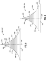
- Figure 5 is a sectional view of the composite radius filler 200 of Figure 4 in an as-formed condition 206 (e.g., Figures 17 and 30 ).
- the radius filler 200 in the as-formed condition 206 is an intermediate shape between the as-stacked condition (e.g., Figures 6 and 27 ) and the as-assembled condition 207 (e.g., Figures 3 and 25 ).
- the radius filler 200 in the as-formed condition 206 is configured to be installed within a part cavity 142 of a composite structure 118.
- a radius filler 200 in an as-formed condition 206 may be installed within a part cavity 142 between the back-to-back L-shaped charges 130 ( Figures 3-4 ) of a blade stringer 121.
- the part cavity 142 has opposing cavity sides 144 ( Figures 3-4 ) defined by the corresponding opposing outside radii 140 ( Figure 4 ) of the web-flange transitions 136.
- the radius filler sides 210 may have a variable radius along a lengthwise direction 202 of at least a portion of the radius filler 200 to accommodate variable outside radii 140 of the part cavity 142 along the lengthwise direction 202.
- the opposing radius filler sides 210 are preferably contoured complementary to the cavity sides 144.
- the radius filler 200 in the as-formed condition 206 is installed in the part cavity 142, the radius filler 200 assumes the as-assembled condition 207 (e.g., Figures 3 and 25 ) wherein the radius filler sides 210 conform to the outside radii 140 of the part cavity sides 144.
- the contour (e.g., the radii) of the radius filler sides 210 in the as-assembled condition 207 may be slightly different (e.g., different radii) than the contour (e.g., the radii) of the radius filler sides 210 in the as-formed condition 206.
- Figure 6 is a sectional view of the radius filler 200 of Figure 5 in an as-stacked condition 204 prior to forming into the as-formed condition 206.
- the radius filler 200 includes a base portion 238 and a tip portion 220 positioned on top of the base portion 238.
- the base portion 238 is formed of composite plies 258 that vary in overall width along the lengthwise direction 202 ( Figure 2 ) of the transition zone 294 ( Figure 18 ).
- the base portion 238 has a variable cross-sectional shape within the transition zone 294.
- the transition zone 294 ( Figure 18 ) has a transition start 296 ( Figure 18 ) and a transition end 298 ( Figure 18 ) as described below.
- the composite plies 258 of the base portion 238 are arranged in one or more stacks 250.
- Each stack 250 is formed as a laminated charge of composite plies 258 arranged in a predetermined fiber orientation angle 262 sequence, as shown in Figure 13 , 21 , and 23 , and described below.
- the composite ply material may be a pre-impregnated fiber-reinforced polymer matrix material (i.e., prepreg) having a plurality of reinforcing fibers impregnated with thermosetting or thermoplastic matrix material or resin.
- the prepreg material may be an epoxy resin/carbon-fiber prepreg.
- the prepreg may be provided in a relatively small ply thickness (e.g., Figure 21 ).
- the prepreg may be provided in a standard ply thickness 260 of approximately 0.0193 cm (0.0076 inch), although the composite plies 258 used to form the presently-disclosed radius filler 200 may be provided in any thickness, without limitation.
- prepreg plies may be provided in thicknesses as small (several thousandths of 2,54 cm (an inch)), as large as one or more ten thousandths of 2,54 cm (an inch), or in any thickness in between.
- each one of the stacks 250 in the base portion 238 has a stack width 278, 282 (e.g., Figure 31 ) that is complementary to the width of the part cavity 142 (e.g., the part cavity in the composite spar 170 of Figure 32 ) at the vertical location of the stack 250.
- the stack width 278, 282 of at least one of the stacks 250 in the base portion 238 changes or tapers within the transition zone 294 ( Figure 34 ) of the radius filler 200.
- the stacks 250 have a constant stack width 278, 282.
- the stack width 278, 282 are constant in the acreage 122 ( Figure 34 ) and the runout 124 ( Figure 34 ) of the radius filler 200, as described below.
- the tip portion 220 is made up of a plurality of composite plies 258 formed into a generally triangular cross-sectional shape and stacked on top of the base portion 238.
- the composite plies 258 in the tip portion 220 are unidirectional slit tape tows 222.
- Unidirectional slit tape tows 222 may be formed by slitting sheets of prepreg composite ply material along a lengthwise direction to form a plurality of relatively narrow-width tows.
- slit tape tow 222 may be provided in widths of 0.635 cm, 1.27 cm (1 ⁇ 4 inch, 1 ⁇ 2 inch), or any one a variety of different tow widths.
- each unidirectional slit tape tow 222 are oriented in a single direction which is parallel to the lengthwise direction of the slit tape tow 222.
- the tip portion 220 may be made up of other forms of tow, and is not limited to unidirectional slit tape tow 222.
- Figure 7 shows an example of a system for manufacturing the tip portion 220 of a radius filler 200.
- a plurality of unidirectional slit tape tows 222 are drawn from spools 224 and are passed through a pultrusion die 310.
- Figure 8 illustrates a lengthwise section of a unidirectional slit tape tow 222 which may be drawn from a spool 224.
- the slit tape tow 222 has a relatively small ply thickness 260 (e.g., approximately 0.019304 cm (0.0076 inch)) and may have a tow width 226 of between approximately 0.3048 and 1.27cm (0.12 and 0.50 inch) prior to pultruding with other slit tape tows 222 through the pultrusion die 310.
- the tip portion 220 of the radius filler 200 may be comprised of anywhere from 4 to 9 slit tape tows 222 each having a tow width 226 of approximately 0.635 cm (0.25 inch). However, a tip portion 220 may be fabricated with less than 4 tows or more than 9 tows.
- a tip portion 220 may be fabricated with slit tape tows 222 having a tow width 226 of other than 0.635 cm (0.25 inch) .
- a tip portion 220 may be fabricated with slit tape tows 222 in two or more different tow widths 226.
- Figure 9 is a perspective view of an example of a pultrusion die 310 having a die opening through which the slit tape tows 222 are passed to conform and consolidate the slit tape tows 222 into a triangular cross-sectional shape.
- Figure 10 illustrates a lengthwise section of the tip portion 220 which may have a cross-sectional size and shape that is generally constant along the length of the tip portion 220.
- a tip portion 220 may be fabricated in a manner such that the tip portion 220 has a variable cross-sectional shape along one or more lengthwise sections of the tip portion 220.
- one or more slit tape tows 222 may be added or dropped during the process of manufacturing (e.g., pultruding) a tip portion 220, resulting in the tip portion 220 having a variable cross-sectional size and/or shape along the lengthwise direction 202.
- the tip portion 220 cross-sectional size and/or shape may be configured to vary in correspondence with the changing outside radii ( Figure 3-4 ) of the part cavity 142 ( Figures 3-4 ) of a composite structure 118.
- FIG 11 is a sectional view of the tip portion 220 of Figure 10 illustrating the non-planar cross-sectional shape of each slit tape tow 222 as a result of the slit tap tows 222 being smashed together during pultrusion through the pultrusion die 310.
- the tip portion 220 has a tip portion apex 236, opposing tip portion sides 234, and a tip portion bottom surface 228.
- the tip portion bottom surface 228 may be generally planar to facilitate the stacking of the tip portion 220 on top of the base portion 238.
- fabricating the tip portion 220 from unidirectional slit tape tows 222 improves manufacturability and structural performance of the radius filler 200 relative to radius filler 200 having tip portions 220 that include laminated composite plies 258.
- Figure 12 is a sectional view of an example of a base portion 238 of a radius filler 200 assembled from a plurality of three-ply stacks 254 each containing three composite plies 258.
- the base portion 238 has a stepped pyramidal cross-sectional shape made up of a bottom stack 276 and one or more mid stacks 280 assembled on top of the bottom stack 276.
- the base portion 238 may include anywhere from 3 to 20 stacks 250 (e.g., including the bottom stack 276 and the mid stacks 280) of composite plies 258.
- a base portion 238 may include any number of stacks 250.
- the section of the base portion 238 containing three-ply stacks 254 is located in the acreage 122 ( Figure 18 ) of the radius filler 200.
- the base portion 238 includes a plurality of two-ply stacks 256 due to the ply termination 274 of the 0 degree plies 264 within the transition zone 294 interconnecting the acreage 122 to the runout 124.
- FIG 13 is a perspective view of the top two three-ply stacks 254 of the base portion 238 of Figure 12 wherein each three-ply stack 254 consists of a +non-zero degree ply 266, a -non-zero degree ply 270, and a 0 degree ply 264 located between the +non-zero degree ply 266 and the -non-zero degree ply 270.
- Each one of the composite plies 258 in the three-ply stack 254 is a unidirectional ply having reinforcing fibers oriented in a single direction.
- each three-ply stack 254 has a stack thickness 252 of approximately 0.057912 cm (0.0228 inch).
- the absolute value of the fiber orientation angle 262 of the +non-zero degree ply 266 and the -non-zero degree ply 270 is equal, such that each three-ply stack 254 is a balanced layup to minimize residual thermal stresses during curing.
- the fiber orientation angle 262 of the +non-zero degree ply 266 and the -non-zero degree ply 270 is preferably less than 45 degrees.
- the fiber orientation angle 262 sequence of each three-ply stack 254 consists of a +30 degree ply 268, a - 30 degree ply 272, and a 0 degree ply 264 located between the +30 degree ply 268 and the -30 degree ply 272.
- the bending stiffness characteristics of the radius filler 200 along the lengthwise direction 202 can be more precisely controlled by adding or dropping stacks 250.
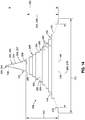
- Figure 14 is a sectional view of a radius filler 200 in an as-stacked condition 204 (shown in solid lines) illustrating a vertical overfill 248 of the radius filler 200 relative to the cross-sectional profile of the part cavity 142 (shown in dashed lines) into which the radius filler 200 in the as-formed condition 206 (e.g., Figure 17 ) is to be installed.
- the dashed lines in Figure 14 represent the shape and size of the part cavity 142 as defined by the opposing cavity sides 144 which extend from the cavity base 146 to the cavity apex 148. The distance from the cavity base 146 to the cavity apex 148 defines the cavity height 150.
- the opposing cavity sides 144 are defined by the opposing outside radii 140 of the back-to-back composite charges of the stringer 120, such as the back-to-back L-shaped charges 130 shown in Figures 3-4 .
- the cavity base 146 is defined by the base charge 128 ( Figure 3-4 ) or skin panel 116 ( Figure 1 ) to which the stringer 120 is ultimately co-cured or co-bonded.
- the radius filler 200 in the as-formed condition 206 (e.g., Figures 17 and 30 ) is installed in the part cavity 142
- the radius filler 200 assumes the as-assembled condition 207 (e.g., Figures 3 and 25 ) wherein the radius filler sides 210 conform to the outside radii 140 of the part cavity sides 144.
- the contour (e.g., the radii) of the radius filler sides 210 in the as-assembled condition 207 may be slightly different (e.g., different radii) than the contour (e.g., the radii) of the radius filler sides 210 in the as-formed condition 206.
- the vertical overfill 248 may be provided by a radius filler 200 in the as-stacked condition 204 having a cross-sectional area that overfills the cross-sectional area of the part cavity 142.
- the tip portion 220 has a tip portion bottom surface 228, and the base portion 238 has a base portion bottom surface 246 and a base portion height.
- the base portion 238 is designed to provide the radius filler 200 in the as-stacked condition 204 with a vertical overfill 248 of the part cavity 142 according to the following criteria: (1) the as-stacked base portion height 242 of the radius filler 200 in the as-stacked condition 204 is at least 5 percent greater than an as-assembled base portion height 243 of the radius filler 200 in the as-assembled condition 207 and, (2) the as-stacked base portion height 242 of the radius filler 200 in the as-stacked condition 204 is at least one additional ply thickness 260 (e.g., Figures 21 and 23 ) beyond the as-assembled base portion height 243.
- the as-stacked base portion height 242 extends from the base portion bottom surface 246 to the tip portion bottom surface 228 of the radius filler 200 in the as-stacked condition 204.
- the as-assembled base portion height 243 extends from the cavity base 146 to the location of the tip portion bottom surface 228 if the tip portion 220 were installed in the part cavity 142 such that the tip portion 220 is in the as-assembled condition 207.
- the location of the tip portion bottom surface 228 when the radius filler 200 is in the as-assembled condition 207 may be determined by analysis or by measuring (e.g., physically, ultrasonically in a laboratory, etc.) the location of the tip portion bottom surface 228 relative to the cavity base 146 with the tip portion in the part cavity 142 and conformed to the part cavity sides 144 in the as-assembled condition 207.
- the location of the tip portion bottom surface 228 is such that the cross-sectional area of the tip portion 220 in the as-assembled condition 207 is equal to the cross-sectional area of the tip portion 220 in the as-stacked condition 204.
- the width of the one or more composite plies 258 added to meet the above-described vertical overfill 248 criteria may be substantially equivalent (e.g., within ⁇ 0.0254 cm ( ⁇ 0.010 inch)) to the part cavity width 152 at the intersection 285 of the cavity sides 144 with a mid-plane 284 of the additional composite plies 258.
- the one or more additional composite plies 258 for vertical overfill 248 may be added on top of the mid-stacks 280 of the base portion 238 in the as-stacked condition 204.
- the one or more composite plies 258 added to meet the vertical overfill 248 criteria comprises three additional composite plies 258 (e.g., a three-ply stack 254) added to meet the vertical overfill 248 criteria.
- the addition of one or more composite plies 258 for vertical overfill 248 may either be a single composite ply 258, two composite plies 258, or more than three composite plies 258 added to meet the above-described vertical overfill 248 requirements at any lengthwise section of a stringer 120.
- the vertical overfill 248 criteria may be met by adding at least one three-ply stack 254 (as described above), such as in the acreage 122 of a stringer 120.
- the vertical overfill 248 criteria may be met by adding at least one two-ply stack 256 (as described below).
- the vertical overfill 248 is at least 5 percent as described above, the vertical overfill 248 is not necessarily constant along the length of the radius filler 200, and may vary with changes in the stringer gauge and/or with changes in the web angle 218 ( Figures 25-27 ) between the webs 132 and flanges 134, as described below.
- the tip portion 220 has a tip portion height 232, a tip portion width 230, and a tip portion side 234 shape that may change with changes in the stringer gauge and/or web angle 218, as described in greater detail below.
- the part cavity 142 has opposing cavity sides 144 respectively defined by the opposing outside radii 140 of the back-to-back composite charges ( Figures 3-4 ).
- the base portion 238 consists of a single bottom stack 276 and a plurality of mid stacks 280 on top of the bottom stack 276. Each one of the mid stacks 280 has a mid stack width 282 which is set to the nominal width of the part cavity 142.
- the base portion 238 in the as-stacked condition 204 may be designed with minimal or non-existent overfill in the horizontal direction.
- the mid stack width 282 of each one of the mid stacks 280 of the base portion 238 in the as-stacked condition 204 is substantially equivalent (e.g., within ⁇ 0.0254 cm ( ⁇ 0.010 inch)) to the part cavity width 152 at the intersection 285 of the cavity sides 144 with a mid-plane 284 of the respective mid stack 280.
- the bottom stack 276 has a bottom stack width 278 that is less than the part cavity width 152 at the part cavity 142 bottom surface.
- the bottom stack width 278 is approximately 0.254 cm (0.10 inch) ⁇ 0.0254 cm ( ⁇ 0.010 inch) less than the part cavity bottom width 153 which may be defined as the distance between the intersections or tangency of the cavity sides 144 with the base charge 128 ( Figure 3 ) or skin panel 116 to which the stringer 120 is co-bonded or co-cured.
- the radius filler 200 to have a vertical overfill 248 and minimal or non-existent horizontal overfill significantly improves compaction of the radius filler 200 and reduces susceptibility to cracking in the radius filler 200, relative to the reduced amount of compaction provided by radius fillers that rely on horizontal overfill.
- the improved compaction and reduced crack susceptibility due to the use of vertical overfill 248 in the presently-disclosed radius filler 200 advantageously improves the structural performance of the stringer 120 such as improved pull-off capability.
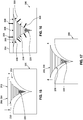
- Figure 15 shows a radius filler 200 in an as-stacked condition 204 and inverted prior to installation into a die cavity 302 of a forming die 300 in a non-limiting example of a system for forming the as-stacked condition 204 of the radius filler 200 into an as-formed condition 206.
- any one of a variety of systems may be implemented for forming an as-stacked 204 radius filler 200 into an as-formed 206 radius filler 200.
- the die cavity 302 may substantially duplicate the size and shape of the part cavity 142 of the composite structure 118 into which the radius filler 200 is to be installed in the as-formed condition 206.
- the die cavity 302 may be contoured complementary to lengthwise variations in the opposing outside radii 140 ( Figures 3-4 ) of the part cavity 142.
- Figure 16 shows the radius filler 200 installed in the forming die 300 and encapsulated by a pressure plate 304 mounted on top of the forming die 300. Also shown is the application of heat 308 and/or pressure 306 to the radius filler 200 within the forming die 300.
- the heat 308 and/or pressure 306 may be applied to the radius filler 200 in a predetermined heat-pressure cycle to debulk and/or consolidate the radius filler 200.
- the application of heat 308 may reduce the resin viscosity in the prepreg composite plies 258 and the slit tape tows 222 that make up the radius filler 200, allowing the composite material under pressure 306 to conform to the cross-sectional shape of the die cavity 302.
- Figure 17 shows the radius filler 200 in the as-formed condition 206 after removal from the forming die 300.
- heat 308 may be applied in a manner avoiding full cure of the resin such that the radius filler 200 may be removed from the die cavity 302 in a partially-cured green state.
- the radius filler 200 in the as-formed condition 206 may be installed into the part cavity 142 of a composite structure 118 such that the radius filler 200 conforms to the contour of the part cavity side 144 and wherein the radius filler 200 is in an as-assembled condition 207 as described above, for final co-curing and/or co-bonding with the composite charges that make up the stringer 120.
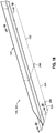
- Figure 18 shows a lengthwise section of an example of a blade stringer 121 having a constant-gauge acreage 122 section connected by a varying-gauge transition zone 294 to a constant-gauge runout 124 at the stringer end 126 of the stringer 120.
- the acreage 122 of the stringer 120 and radius filler 200 may be described as a constant gauge section that is not located at the runout 124.
- the transition zone 294 may be described as a section of the stringer 120 and radius filler 200 that is of varying gauge from one constant-gauge section to another constant-gauge section.
- the runout 124 may be described as a constant-gauge section of the stringer 120 and radius filler 200.
- a runout 124 may be located at one stringer end 126 or at both stringer ends 126.
- the radius filler 200 may include a runout 124 at the inboard end 112 ( Figure 38 ) of the stringer 120, at the outboard end 114 ( Figure 38 ) of the stringer 120, or at both the inboard end 112 and the outboard end 114 of the stringer 120.
- the thickness or gauge of the stringer 120 and the radius filler 200 in a runout 124 is relatively thin compared to the thickness in the constant-gauge acreage 122 sections of the radius filler 200.
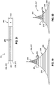
- Figure 19 is a sectional view of the radius filler 200 in the as-formed condition 206 and which may be assembled with the stringer 120 of Figure 18 in the constant-gauge acreage 122 of the stringer 120.
- the tip portion 220 of the radius filler 200 in the acreage 122 preferably includes from 4 to 9 slit tape tows 222, each of which may be approximately 0.635 cm (0.25 inch) wide. However, the tip portion 220 may include any number of slit tape tows 222 of any tow width 226.
- the base portion 238 of the radius filler 200 in the acreage 122 preferably includes from 5 to 17 three-ply stacks 254, although the base portion may include any number of three-ply stacks 254.
- Figures 19 is an example of a radius filler 200 as may be installed in in a relatively heavy-gauge acreage 122 section of a stringer 120.
- the radius filler 200 may have a tip portion 220 containing 16 continuous slit tape tows 222 each having a tow width 226 of approximately 0.3175 cm (0.125 inch), or 8 continuous slit tape tows 222 each having a tow width 226 of approximately 0.635 cm(0.25 inch).
- the base portion 238 of the radius filler 200 in Figure 19 consists of 14 three-ply stacks 254.
- the bottom stack 276 of the base portion 238 may have a bottom stack width (not shown) of approximately 2.794 cm (1.1 inch) and the uppermost mid stack 286 (e.g., located directly below the tip portion 220) may have a stack width (not shown) of approximately 0.4064 cm (0.16 inch).
- Figure 20 illustrates an example of a radius filler 200 in an as-formed condition 206 for a relatively light-gauge acreage 122 section, and wherein the above-described tip portion 220 contains the above-mentioned 8 slit tape tows 222 of 0.635 cm (0.25 inch) width.
- the base portion 238 of the radius filler 200 in Figure 20 consists of 6 three-ply stacks 254.
- the bottom stack 276 of the base portion 238 has a bottom stack width (not shown) of approximately 1.8542 cm (0.73 inch) and the uppermost mid stack 286 may have a mid stack width (not shown) of approximately 0.508 cm (0.20 inch).
- Figure 21 is a sectional view of the uppermost 286 three-ply stack 254 of the base portion 238 of Figures 19 and 20 and illustrating the three composite plies 258 that make up the three-ply stack 254.
- the stack thickness 252 of each three-ply stack 254 is approximately 0.057912 cm (0.0228 inch).
- Each three-ply stack 254 in the base portion 238 of the acreage 122 preferably has a fiber orientation angle 262 sequence consisting of a +30 degree ply 268, a -30 degree ply 272, and a 0 degree ply 264 located between the +30 degree ply 268 and the -30 degree ply 272.
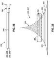
- Figure 22 is a sectional view of the radius filler 200 taken in the constant-gauge runout 124 of the stringer 120 of Figure 18 .
- the tip portion 220 in a runout 124 preferably includes from 4 to 9 slit tape tows 222 of 0.635 cm (0.25 inch) width.
- the base portion 238 of the radius filler 200 in a runout 124 preferably includes from 5 to 10 two-ply stacks 256.
- a two-ply stack 256 contains no 0 degree plies 264, and is formed due to the termination in the transition zone 294 of the 0 degree ply 264 of the three-ply stack 254.
- each two-ply stack 256 in the base portion 238 of a runout 124 preferably has a fiber orientation angle 262 sequence consisting of a +30 degree ply 268 and a -30 degree ply 272.
- the base portion 238 consists of 6 three-ply stacks 254.
- Figure 23 is a sectional view of the uppermost 286 two-ply stack 256 of the base portion 238 of Figure 22 .
- the two composite plies 258 that make up the two-ply stack 256 are a +30 degree ply 268 and a -30 degree ply 272 and which are a continuation of such plies in the three-ply stack 254.
- the stack thickness 252 of a two-ply stack 256 is approximately 0.038608 cm (0.0152 inch).
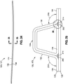
- Figure 24 is a side view of a hat stringer 172 having a hat-shaped cross-section.
- Figure 25 is a sectional view of the hat stringer 172 taken along line 25 of Figure 24 and illustrating a pair of asymmetric radius fillers installed in the hat stringer 172.
- the hat stringer 172 may be made up of a planar base charge 128, a trapezoidal wrap charge 178, a hat-shaped primary charge 176, and a pair of asymmetric radius fillers 200.
- the base charge 128, wrap charge 178, and primary charge 176 may each be separately formed as a laminate of composite plies 258. The assembly of the base charge 128, wrap charge 178, and primary charge 176 results in a pair of part cavities 142.
- the webs 132 may be oriented at a non-perpendicular web angle 218 to the flanges 134.
- the web angle 218 on each side of the hat stringer 172 may be up to 105° or more.
- a hat stringer 172 may have webs 132 that are oriented at a perpendicular web angle 218 relative to the flanges 134.
- the part cavity 142 has opposing outside radii 140 that may be unequal.
- the opposing outside radii 140 may be equal along one or more lengthwise sections and unequal along one or more other lengthwise sections of a hat stringer 172 having either perpendicular web angles 218 or non-perpendicular web angles 218.
- the web angle 218 for a hat stringer 172 may be constant along the lengthwise direction of the stringer 172. However, in other examples, the web angle 218 for a hat stringer 172 may vary along the lengthwise direction of the stringer 172.
- the radius filler 200 in the as-stacked condition 204 is sized and configured to fill the part cavity 142 when the base charge 128 is assembled with the wrap charge 178 and primary charge 176.
- the base charge 128, wrap charge 178, primary charge 176, and radius fillers 200 may be co-bonded or co-cured to a skin panel 116 ( Figure 1 ).
- the base charge 128 may be omitted, and the wrap charge 178, primary charge 176, and radius fillers 200 may be assembled directly onto a skin panel (not shown) for co-curing or co-bonding.
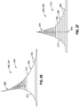
- Figure 26 is a sectional view of a radius filler 200 in an as-formed condition 206 as may be installed in a part cavity of the hat stringer 172 of Figure 25 .
- the radius filler 200 in an as-formed condition 206 has an asymmetric shape 214 wherein the opposing radius filler sides 210 have unequal outside radii 140, as distinguished from a radius filler 200 having a symmetric shape 212 about a vertical centerline as shown in Figure 5 wherein the outside radii 140 of the opposing radius filler sides 210 are equal.
- the asymmetrically-shaped radius filler 200 of Figure 26 includes the tip portion 220 and the base portion 238, and is constructed in a manner similar to the above-described construction of a symmetrically-shaped radius filler 200.
- the radius filler 200 of Figure 26 incorporates the above-described vertical overfill 248 criteria.
- Figure 27 is a sectional view of an example of a radius filler 200 in an as-stacked condition 204 having an asymmetric shape 214.
- the asymmetric radius filler 200 may be formed into an as-formed condition 207 (e.g., see Figures 28-30 ) and assembled with a stringer 120 to result in the as as-assembled condition 207 of the radius filler 200 shown in Figure 25 .
- a symmetrically-shaped radius filler 200 in an as-stacked condition 204 may be formed into a radius filler 200 in an as-formed condition 206 having an asymmetric shape 214, and which may be assembled with a stringer 120 to result in the as-assembled condition 207 shown in Figure 26 .
- Figures 28-30 illustrate an example of a process of forming a radius filler 200 having an asymmetric shape 214 in an as-stacked condition 204 into a radius filler 200 having an asymmetric shape 214 in an as-formed condition 206.
- Figure 28 illustrates a radius filler 200 having an asymmetric shape 214 in an as-stacked condition 204 prior to installation into an asymmetrically-shaped die cavity 302 of a forming die 300 which may substantially duplicate the asymmetrical shape of a part cavity 142 into which the radius filler 200 is to be installed. Insertion of the radius filler 200 into the die cavity 302 and/or the application of heat 308 and/or pressure 306 causes the tip portion 220 and the base portion 238 to conform to the contour of the die cavity 302.
- Figure 29 shows the application of heat 308 and/or pressure 306 to the radius filler 200 within the forming die 300 after a pressure plate 304 is mounted on top of the forming die 300.
- the application of pressure 306 and the reduction in resin viscosity due to the application of heat 308 causes the base portion 238 and tip portion 220 to conform to the sides of the die cavity 302.
- Figure 30 shows the radius filler 200 in the as-formed condition 206 having an asymmetric shape 214 after removal from the forming die 300.
- the radius filler 200 in the as-formed condition 207 may be installed in a part cavity of a stringer 120 to result in the radius filler shown in the as-assembled condition 207 in Figure 25 .
- a radius filler 200 in the as-stacked condition 204, the as-formed condition 206, and/or the as-assembled condition 207 may have a symmetric shape 212 that is constant along an entire length of the radius filler 208.
- a radius filler 200 in the as-stacked condition 204, the as-formed condition 206, and/or the as-assembled condition 207 may have an asymmetric shape 214 that is constant along an entire length of the radius filler 208.
- a radius filler 200 in the as-stacked condition 204, the as-formed condition 206, and/or the as-assembled condition 207 may include one or more lengthwise sections that have a symmetric shape 212 that transitions along the length of the radius filler 200 into an asymmetric shape 214.
- a radius filler 200 may have a symmetric shape 212 ( Figure 9 ) in an as-stacked condition 204 along an entire length of the radius filler 200, and at least a portion of the length of the symmetrically-shaped radius filler 200 in the as-stacked condition 204 may be formed into an asymmetric shape 214 ( Figure 26 ) and/or assembled into an asymmetric part cavity 142.
- a radius filler 200 may be provided in a symmetric shape 212 in an as-stacked condition 204 and an as-formed condition 206, and may have an asymmetric shape 214 in an as-assembled condition 207 along at least a lengthwise portion of the radius filler 200 when installed in the part cavity 142 of the blade stringer 121.
- a radius filler 200 may be provided in an asymmetric shape 214 in an as-stacked condition 204 and an as-formed condition 206, and may have an asymmetric shape 214 in an as-assembled condition 207 along at least a lengthwise portion of the radius filler 200 when installed in the part cavity 142 of the hat stringer 172.
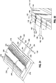
- Figure 31 is a perspective view of a lengthwise section of a base portion 238 made up of a plurality of stacks 250.
- the base portion 238 has a variable cross-sectional shape as a result of tapers in the stack widths 278, 282 of one or more of the stacks 250.
- Figure 31 illustrates the termination of the uppermost stack 286 of the base portion 238.
- a terminating end of a stack 250 may have a non-square shape such as a generally pointed shape or a rounded shape (not shown), and which may improve the ability of the radius filler 200 to fill the volume of the part cavity 142.
- a terminating end of a stack 250 may have a square shape (not shown).
- transition zones 294 of a radius filler 200 changes in stack width 278, 282 and additions or dropping of stacks 250 are limited to the transition zones 294 of a radius filler 200.
- the acreage 122 and the runout 124 of a radius filler 200 have constant stack widths 278, 282 and do not have any additions or dropping of stacks 250.
- a transition zone 294 may interconnect a pair of acreage 122 sections, or a transition zone 294 may connect an acreage 122 section to a runout 124 ( Figure 37-38 ) located at one or both of opposing ends of a radius filler 200.
- the transition zone 294 comprises a change in at least one of a general base portion width 240 ( Figure 14 ) and a base portion height 242 ( Figure 14 ) in correspondence with the location of ply drops 156 and/or ply additions 162 along the lengthwise direction 202 of the composite structure 118 into which the radius filler 200 is to be installed.
- Figure 32 shows a lengthwise section of a composite spar 170 illustrating a part cavity 142 into which a radius filler 200 is to be installed. Also shown is the changing thickness of the spar 170 along the lengthwise direction 202 as a result of localized ply additions 162 and ply drops 156 in the spar 170. Ply additions 162 and ply drops 156 may result in variations in the outside radii 140 ( Figures 3-4 ) along the lengthwise direction 202 of the spar 170.
- the variable cross-sectional shape of the radius filler 200 is complementary to the variations in outside radii 140 of the spar 170.
- the inside radii 138 ( Figures 3-4 ) of the spar 170 may be substantially constant along the lengthwise direction 202 which may improve the inspectability of the spar 170 and may reduce manufacturing costs.
- a symmetric radius filler 200 e.g., Figure 5
- a composite structure e.g., a symmetric composite spar
- the lengthwise location of the transition zones 294 are slightly offset from the lengthwise location of ply drops 156 and/or ply adds in the composite structure.
- Figure 33 is a schematic top view of a bottom stack 276 of a base portion 238 of a symmetric radius filler 200 (e.g., Figure 5 ) showing the offset 154 of a transition zone 294 from the start 158 and end 160 of a ply drop 156 in a stringer 120 having a symmetric cross-section (e.g., Figure 3 ), and showing the offset 154 of another transition zone 294 from the start 164 and end 166 of a ply addition 162 to the stringer 120.
- the transition start 296 of a transition zone 294 may be located after the start 158 of a ply drop 156, and the transition end 298 of the transition zone 294 may be located after the end 160 of the ply drop 156.
- the transition start 296 of a transition zone 294 may be located before the start 164 of a ply addition 162, and the transition end 298 of the transition zone 294 may be located before the end 166 of the ply addition 162.
- a transition zone 294 may be offset 154 from the start of a ply drop 156 or ply addition 162 by a distance of approximately 0.254 to 1.27 cm (0.10 to 0.50 inch) or more.
- the transition zone 294 may not be offset from ply drops 156 or ply additions 162.
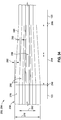
- Figure 34 is a top view of a base portion 238 of a radius filler 200 in an as-stacked condition 204 and illustrating a transition zone 294 interconnecting two acreage 122 sections.
- the stack widths 278, 282 of the stacks 250 in the base portion 238 are constant, and there are no additions or dropping of stacks 250 (i.e., no stack terminations), the combined effect of which results in the radius filler sides 210 ( Figure 5 ) having a constant radius along the length of the acreages 122.
- one or more stacks 250 may be added or dropped.
- all of the plies 258 in the stack 250 terminate at the same location as shown in Figure 35 described below.
- a radius filler 200 may include any number of transitions zones 294 at any location along the lengthwise direction 202 of the radius filler 200 in correspondence with ply drops 156 and ply additions 162 in the stringer 120.
- the spacing between the stack terminations 288 and the transition start 296 and transition end 298 may be equal to the length of the transition zone 294 divided by the total quantity of stack terminations 288.
- the stack widths 278, 282 of one or more of the stacks 250 may change or vary linearly between adjacent acreage 122 sections.
- a change in stack width 278, 282 may comprise a taper 290 that extends from the transition start 296 to the transition end 298.
- the stacks 250 have taper angles 292 that differ from one another.
- the combined effect of stack terminations 288 and changes in stack width 278, 282 in a transition zone 294 results in the radius filler sides 210 ( Figure 5 ) having a varying radius along the lengthwise direction 202 of the transition zone 294.
- Figure 35 is a diagrammatic side sectional view of a base portion 238 of a radius filler 200 in the as-stacked condition 204 and illustrating a stack termination 288 of a three-ply stack 254 within a transition zone 294 interconnecting two acreage 122 sections in the approximate lengthwise middle of the radius filler 200. Also shown are ply terminations 274 of the 0 degree plies 264 at a transition zone 294 at each of the inboard end 112 and the outboard end 114 of the radius filler 200, and wherein each transition zone 294 connects an acreage 122 to a runout 124.
- the 0 degree ply 264 in each of the three-ply stacks 254 terminates at a ply termination 274 located either at the transition start 296, at the transition end 298, or within the transition zone 294.
- a plurality of three-ply stacks 254 can be manufactured by laying up a three-ply laminate (not shown) consisting of a +non-zero degree ply sheet (not shown), a -non-zero degree ply sheet (not shown), and a 0 degree ply sheet (not shown) located between the sheets (not shown) of the +non-zero degree ply and the -non-zero degree ply.
- a sheet for the 0 degree ply 264 of a stack 250 may be provided in a length that will extend from the transition zone 294 at one stringer end 126 to the transition zone 294 at the opposite stringer end 126.
- a 0 degree ply 264 may extend beyond an end of the radius filler 200.
- a sheet for the +non-zero degree ply 266 and the -non-zero degree ply 270 may each be provided in equal lengths.
- a sheet for the +non-zero degree ply 266 and the -non-zero degree ply 270 may each be longer than the sheet for the 0 degree ply 264 such that the stacks 250 will extend beyond the ends of the part (e.g., ends of the stringer) and can be trimmed off at a later time.
- the +non-zero degree ply 266 sheet and the -non-zero degree ply 270 sheet may each be provided in a length such that the ends of the +non-zero degree ply 266 and the -non-zero degree ply 270 extend beyond each one of the opposing ends of the 0 degree ply 264, as shown in Figure 35 .
- the three-ply laminate sheet can be slit along a lengthwise direction 202 into a plurality of individual three-ply stacks 254, each having the required stack width 278, 282 as described above with regard to Figure 14 .
- the individual three-ply stacks 254 may be stacked on top of one another to form the stepped pyramidal cross-sectional shape of the base portion 238 with the required vertical overfill 248, as described above and illustrated in Figure 14 .
- the individual stacks 250 can be staggered along a lengthwise direction 202 such that at the transition zones 294, the ply terminations 274 of the 0 degree plies 264 are spaced apart from one another. More specifically, for the transition zone 294 on at least one stringer end 126, the ply terminations 274 are spaced apart from one another and from the transition start 296 and transition end 298 by a distance approximately equal to the length of the transition zone 294 divided by the total quantity of ply terminations 274 (e.g., of 0 degree plies 264) at the transition start 296, at the transition end 298, and/or within the transition zone 294.
- the ply terminations 274 are spaced apart from one another and from the transition start 296 and transition end 298 by a distance approximately equal to the length of the transition zone 294 divided by the total quantity of ply terminations 274 (e.g., of 0 degree plies 264) at the transition start 296, at the transition end 298, and/or within the transition zone 294.
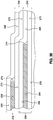
- Figure 37 is a top view rotated 180° of the transition zone 294 at the inboard end 112 of the base portion 238 of Figure 35 and showing the equal spacing s between the ply terminations 274 of the 0 degree plies 264.
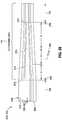
- Figure 38 is a top view of the transition zone 294 at the outboard end 114 of the base portion 238 of Figure 35 and showing the spacing s of the zero-degree ply terminations 274.
- a stringer 120 may be configured such that the transition zone 294 at one end of the stringer 120 is a different length than the transition zone 294 at the opposite end of the stringer 120.
- the transition zone 294 at the inboard end 112 is longer than the transition zone 294 at the outboard end 114.
- Figure 39 is a top view of an example of a two-ply stack 256 added to the runout 124 and terminating at a stack termination 288 within the transition zone 294 of the radius filler 200.
- the two-ply stack 256 may be added to increase the height of the base portion 238 in the runout 124 in order to meet the above-mentioned vertical overfill 248 ( Figure 14 ) criteria.
- the vertical overfill 248 improves compaction of the stringer 120 and reduces crack susceptibility which improves the structural performance of the stringer 120 such as improved pull-off strength.
- the stack termination 288 of the added two-ply stack 256 may be located midway between the transition start 296 and the transition end 298.
- the stack terminations 288 may be equally spaced from one another and from the transition start 296 and the transition end 298.
- FIG 40 is a flow diagram illustrating one or more operations that may be included in a method 400 of manufacturing a composite radius filler 200.
- Step 402 of the method 400 includes providing a base portion 238 formed of composite plies 258 varying in overall width along at least a portion of an overall lengthwise direction 202 and defining a variable cross-sectional shape of the base portion 238 along the lengthwise direction 202.
- the base portion 238 includes at least one transition zone 294 having a transition start 296 and a transition end 298 along the lengthwise direction 202.
- the composite plies 258 of the base portion 238 are arranged in one or more stacks 250.
- Each stack 250 comprises a laminated charge of composite plies 258 having a predetermined fiber orientation angle 262 sequence and having a stack width 278, 282.
- the stack width 278, 282 of at least one of the stacks 250 changes within the transition zone 294.
- the step of providing the base portion 238 includes providing at least one stack 250 of the base portion 238 as a laminated charge in the form of a three-ply stack 254 ( Figure 13 ) consisting of a +non-zero degree ply 266, a -non-zero degree ply 270, and a 0 degree ply 264 laminated between the +non-zero degree ply 266 and the -non-zero degree ply 270.
- the absolute value of the fiber orientation angle 262 of the +non-zero degree ply 266 and the -non-zero degree ply 270 is equal (e.g., ⁇ 5 degrees).
- the step of providing at least one stack 250 of the base portion 238 can include providing at least one stack 250 of the base portion 238 as a laminated charge consisting of a +30 degree ply 268, a -30 degree ply 272, and a 0 degree ply 264 located between the +30 degree ply 268 and the -30 degree ply 272.
- changes in stack width 278, 282 are limited to the transition zone 294, and do not occur in the acreage 122 or the runout 124 which are constant-gauge sections of the radius filler 200.
- the changes in stack width 278, 282 are linearly varying and form a taper 290 ( Figure 34 ) extending from the transition start 296 to the transition end 298. At least two of the stacks 250 have taper angles 292 that differ from one another.
- Figure 34 illustrates a taper 290 in each one of the stacks 250 in the transition zone 294 which is shown interconnecting a pair of acreage 122 sections on opposite sides of the transition zone 294.
- the method may further include terminating, in at least one of the stacks 250, the 0 degree ply 264 at a ply termination 274 located within a transition zone 294.
- a three-ply stack 254 e.g., in an acreage 122 transitions to a two-ply stack 256 which consists of the +non-zero degree ply 266 (e.g., a +30 degree ply 268) and the -non-zero degree ply 270 (e.g., a -30 degree ply 272) in back-to-back contact with one another as illustrated in Figure 36 .
- the step of terminating a 0 degree ply 264 comprises locating the ply termination 274 at either the transition start 296, within the transition zone 294 (i.e., between the transition start 296 and transition end 298), or at the transition end 298.
- a plurality of 0 degree plies 264 may be terminated such as illustrated in Figure 38 .
- the method may include spacing the ply terminations 274 of the 0 degree plies 264 apart from one another and from the transition start 296 and transition end 298 at a spacing s approximately equal to the length of the transition zone 294 divided by the total quantity of ply terminations 274 at the transition start 296, within the transition zone 294, and at the transition end 298, similar to the arrangement shown in Figure 37 .
- the ply terminations 274 at an opposite end of the radius filler 200 may also utilize the same spacing between some of the ply terminations 274 and may have a different distance d between the ply termination 274 located nearest the transition, similar to the arrangement described above with regard to Figure 38 .
- Step 404 of the method 400 includes providing a tip portion 220 which has a generally triangular cross-sectional shape as shown in Figure 6 .
- the step of providing the tip portion 220 may include pultruding a plurality of prepreg unidirectional slit tape tows 222 into the generally triangular cross-sectional shape.
- Figure 7 illustrates an example of a system that may be implemented for drawing a plurality of unidirectional slit tape tows 222 from spools 224 and passing the slit tape tows 222 through a pultrusion die 310 as shown in Figure 9 .
- the unidirectional slit tape tows 222 may be provided in a tow width 226 of between approximately 0.03048 to 1.27 cm (0.12 to 0.50 inch) prior to pultruding into the generally triangular cross-sectional shape, although other tow widths 226 are contemplated.
- Step 406 of the method 400 includes stacking the tip portion 220 onto the base portion 238 to form a radius filler 200 in an as-stacked condition 204, an example of which is illustrated in the above-described Figure 6 .
- the radius filler 200 is configured to be installed in a part cavity 142 of a composite structure 118.
- the part cavity 142 has a cavity height 150 measured from a cavity base 146 to a cavity apex 148.
- the tip portion 220 has a tip portion bottom surface 228.
- the base portion 238 has a base portion bottom surface 246 and a base portion height 242.
- the method 400 includes forming the radius filler 200 with a vertical overfill 248 ( Figure 14 ) of the part cavity 142.
- vertical overfill 248 may be achieved by designing the radius filler 200 such that: (1) the as-stacked base portion height 242 of the radius filler 200 in the as-stacked condition 204 is at least 5 percent greater than an as-assembled base portion height 243 of the radius filler 200 in the as-assembled condition 207, and (2) the as-stacked base portion height 242 of the radius filler 200 in the as-stacked condition 204 is at least one additional ply thickness 260 (e.g., Figures 21 , 23 ) beyond the as-assembled base portion height 243.
- vertical overfill 248 of the radius filler 200 into a part cavity 142 advantageously results in improved compaction of the composite structure 118 (e.g., stringer 120) and reduces susceptibility to cracking which translates into an improvement in the structural performance of the stringer 120, including improved pull-off strength of the stringer 120.
- the radius filler 200 may be formed with vertical overfill 248 and without horizontal overfill.
- the method may include forming the base portion 238 from a single bottom stack 276 and a plurality of mid stacks 280 each having a stack width 282 that matches the nominal width of the part cavity 142 as shown in Figure 14 .
- the method may include forming the radius filler 200 in the as-stacked condition 204 such that the stack width 282 of each of the mid stacks 280 is substantially equivalent (within ⁇ 0.0254 cm ( ⁇ 0.010 inch)) to the part cavity width 152 at the intersection of the cavity sides 144 with the mid-plane 284 of the mid stack 250, as described above with regard to Figure 14 .
- the bottom stack 276 has a bottom stack width 278 that is less than the part cavity width 152 at a part cavity 142 bottom surface ( Figure 14 ).
- the bottom stack width 278 is approximately 0.254 cm ⁇ 0.0254 cm ((0.10 inch) ( ⁇ 0.010 inch)) less than the part cavity bottom width 153.
- Step 408 of the method 400 includes applying heat 308 and/or pressure 306 to the radius filler 200 to produce a radius filler 200 in as as-formed condition 206.
- the radius filler 200 may be assembled into a symmetric shape 212 ( Figure 6 ) in an as-stacked condition 204, which may be formed into a symmetric shape 212 in an as formed condition 206, such as by applying heat 308 and/or pressure 306 to the as-stacked radius filler 200 within a forming die 300 as described above with regard to Figures 15-17 .
- a radius filler 200 may be assembled into an asymmetric shape 214 ( Figure 27 ) in an as-stacked condition 204.
- At least a lengthwise section of a radius filler 200 with an asymmetric shape 214 in the as-stacked condition 204 may be formed into an asymmetric shape 214 in an as-formed condition 206, such as by using a forming die 300 having an asymmetrical die cavity 302 as described above with regard to Figures 28-30 , or by using any one of a variety of alternative forming means.
- the method may include forming the opposing radius filler sides 210 of the radius filler 200 into a contour that is complementary to the corresponding cavity sides 144 of the part cavity 142 ( Figures 3-4 ) which extends along the lengthwise direction 202 of the composite structure 118.
- each one of the radius filler sides 210 may be formed into a radius that substantially matches the radius of the cavity sides 144.
Landscapes
- Engineering & Computer Science (AREA)
- Mechanical Engineering (AREA)
- Chemical & Material Sciences (AREA)
- Composite Materials (AREA)
- Aviation & Aerospace Engineering (AREA)
- Textile Engineering (AREA)
- Moulding By Coating Moulds (AREA)
- Laminated Bodies (AREA)
Abstract
Description
- The present disclosure relates generally to composite structures and, more particularly, to a composite radius filler for a composite structure.
- Composite structures are used in a wide variety of applications due to their high strength-to-weight ratio, corrosion resistance, and other favorable properties. In aircraft construction, composites are used in increasing quantities to form the fuselage, wings, horizontal and vertical stabilizer, and other components. For example, the wing of an aircraft may be formed of composite skin panels co-cured or co-bonded to internal composite structures such as composite stringers and composite spars. The composite stringers and spars may extend along a spanwise direction from the wing root to the wing tip and may generally taper in thickness along the spanwise direction to gradually reduce the stiffness of the stringer or spar.
- Composite stringers and spars may be provided in a variety of cross-sectional shapes. For example, a composite stringer may be formed in a hat-shaped cross section and referred to as a vent stringer or hat stringer. In another example, a composite stringer may be formed in a T-shaped cross section referred to as a blade stringer. A blade stringer may be formed by bonding together two L-shaped charges in back-to-back arrangement. Each one of the L-shaped charges may have a flange and a web interconnected by a radiused web-flange transition. When the webs of two L-shaped charges are joined back-to-back, a lengthwise notch or part cavity (e.g., a radius filler region) is formed between the opposing web-flange transitions. To improve the strength, stiffness, and durability of the stringer and the bond between the stringer and a skin panel, the part cavity is typically filled with a radius filler which may be referred to as a noodle and which is typically formed of composite material.
- Composite radius fillers suffer from several drawbacks which detract from their overall utility. For example, certain radius fillers may exhibit reduced structural performance due to susceptibility to cracking which may correspond to a relatively low pull-off strength at the bond between the stringer and a skin panel to which the stringer is bonded. Furthermore, certain radius filler configurations have inside radii that vary along a lengthwise direction which may prevent non-destructive inspection (NDI) of the inside radii using acoustic inspection methods. In addition, certain radius filler configurations require the assembly of multiple components to form the radius filler, and which has an adverse impact on manufacturing cost and schedule. Furthermore, certain stringer configurations require a radius filler having an asymmetric shape which is difficult to manufacture using existing radius filler configurations.
- As can be seen, there exists a need in the art for a radius filler that provides improved structural performance including reduced susceptibility to cracking, improved ability to tailor the stiffness characteristics, and improved pull-off strength. Furthermore, there exists a need in the art for a radius filler that improves the inspectability of the composite structure containing the radius filler, and which can also be manufactured in a low-cost and timely manner.
- The above-noted needs associated with radius fillers for composite structures are specifically addressed and alleviated by the present disclosure which provides a composite radius filler including a base portion and a tip portion. The base portion is formed of composite plies varying in overall width along an overall lengthwise direction and defining a variable cross-sectional shape of the base portion along the lengthwise direction. The base portion includes at least one transition zone having a transition start and a transition end along the lengthwise direction. The composite plies of the base portion are arranged in one or more stacks each having a predetermined fiber orientation angle sequence and a stack width that changes within the transition zone. The tip portion includes a plurality of composite plies formed into a generally triangular cross-sectional shape and stacked on top of the base portion.
- Also disclosed is a composite structure including a pair of composite charges in back-to-back contact with one another and forming a lengthwise part cavity. In addition, the composite structure includes a radius filler installed in the part cavity. The radius filler is made up of a base portion and a tip portion. The base portion is formed of composite plies varying in overall width along an overall lengthwise direction and defining a variable cross-sectional shape of the base portion along the lengthwise direction. The base portion includes at least one transition zone. The composite plies of the base portion are arranged in one or more stacks each having a predetermined fiber orientation angle sequence and a stack width that changes within the transition zone. The tip portion includes a plurality of composite plies formed into a generally triangular cross-sectional shape and stacked on top of the base portion.
- Also disclosed is a method of manufacturing a radius filler. The method includes providing a base portion formed of composite plies varying in overall width along at least a portion of an overall lengthwise direction and defining a variable cross-sectional shape of the base portion along the lengthwise direction. The base portion including at least one transition zone. The composite plies of the base portion are arranged in one or more stacks of composite plies having a predetermined fiber orientation angle sequence and having a stack width. The stack width of at least one of the stacks changes within the transition zone. The method may additionally include providing a tip portion having a generally triangular cross-sectional shape, and assembling the tip portion with the base portion to form a radius filler in an as-stacked condition. The method may additionally include applying heat and/or pressure to the radius filler to produce a radius filler having a variable cross-sectional shape.
- These and other features of the present disclosure will become more apparent upon reference to the drawings wherein like numbers refer to like parts throughout and wherein:
-
Figure 1 is a diagrammatic representation of a perspective view of an aircraft comprised of one or more composite structures incorporating one or more composite radius fillers as disclosed herein; -
Figure 2 is a diagrammatic representation of a side view of an example of a composite stringer configured as a blade stringer and having a radius filler as disclosed herein; -
Figure 3 is a diagrammatic representation of a sectional view of a composite stringer (e.g., blade stringer) taken alongline 3 ofFigure 2 ; -
Figure 4 is a diagrammatic representation of an exploded sectional view of a composite stringer ofFigure 3 and illustrating a pair of L-shaped charges, a base charge, and a radius filler; -
Figure 5 is a diagrammatic representation of a sectional view of the radius filler ofFigure 4 in an as-formed condition and which may be assembled with the stringer ofFigure 4 ; -
Figure 6 is a diagrammatic representation of a sectional view of the radius filler ofFigure 5 in an as-stacked condition and illustrating a base portion and a tip portion; -
Figure 7 is a diagrammatic representation of a perspective view of a plurality of unidirectional slit tape tows passing through a pultrusion die; -
Figure 8 is a diagrammatic representation of a perspective view of a lengthwise section of a unidirectional slit tape tow; -
Figure 9 is a perspective view of the pultrusion die ofFigure 7 ; -
Figure 10 is a diagrammatic representation of a perspective view of a lengthwise section of a tip portion having a triangular cross-sectional shape; -
Figure 11 is a diagrammatic representation of a sectional view of the tip portion taken alongline 11 ofFigure 10 and illustrating the non-planar cross-sectional shape of the slit tape tows as a result of being pultruded through the pultrusion die ofFigure 9 ; -
Figure 12 is a diagrammatic representation of a sectional view of an example of a base portion of a radius filler in an as-stacked condition and being assembled of a plurality of three-ply stacks wherein each stack contains three composite plies; -
Figure 13 is a diagrammatic representation of a perspective view of the top two stacks of the base portion ofFigure 12 and illustrating each three-ply stack being having a +non-zero degree ply, a -non-zero degree ply, and a zero degree ply in between the +non-zero degree ply and the -non-zero degree ply; -
Figure 14 is a diagrammatic representation of a sectional view of a radius filler in an as-stacked condition and further illustrating a vertical overfill of the radius filler relative to a cross-sectional profile of a part cavity into which the radius filler in an as-formed condition is to be installed; -
Figure 15 is a diagrammatic representation of a sectional view of a radius filler in an as-stacked condition prior to installation into a forming die; -
Figure 16 is a diagrammatic representation of a sectional view of the application of heat and pressure to the radius filler within the forming die; -
Figure 17 is a diagrammatic representation of a sectional view of the radius filler in the as-formed condition after removal from the forming die; -
Figure 18 is a diagrammatic representation of a perspective view of a lengthwise section of a blade stringer having a constant-gauge acreage interconnected by a varying-gauge transition zone to a constant-gauge runout at an end of the stringer; -
Figure 19 is a diagrammatic representation of a sectional view of a radius filler taken alongline 19 ofFigure 18 and illustrating the radius filler in as-formed condition and which may be installed in a heavy-gauge section in the acreage of the stringer ofFigure 18 ; -
Figure 20 is a diagrammatic representation of a sectional view of a radius filler in as-formed condition for a light-gauge section of a stringer (not shown); -
Figure 21 is a diagrammatic representation of a sectional view of the uppermost three-ply stack of the base portion ofFigures 19 and 20 and illustrating the three composite plies that make up the three-ply stack; -
Figure 22 is a diagrammatic representation of a sectional view of a radius filler taken alongline 22 ofFigure 18 and illustrating the radius filler in as-formed condition and which may be installed in the runout of the stringer ofFigure 18 ; -
Figure 23 is a diagrammatic representation of a sectional view of the uppermost two-ply stack of the base portion ofFigure 22 and illustrating the two composite plies that make up the two-ply stack; -
Figure 24 is a diagrammatic representation of a side view of a composite stringer configured as a hat stringer; -
Figure 25 is a diagrammatic representation of a sectional view of the stringer taken alongline 25 ofFigure 24 and illustrating a pair of asymmetric radius fillers installed in the hat stringer; -
Figure 26 is a diagrammatic representation of a sectional view of a radius filler taken alongsection 26 ofFigure 27 and illustrating the radius filler having an asymmetric shape in an as-formed condition; -
Figure 27 is a diagrammatic representation of a sectional view of a radius filler in an as-stacked condition having an asymmetric shape and which may be formed into the asymmetric shape of the radius filler ofFigure 26 in an as-formed condition for installation into a part cavity resulting in the radius filler having an asymmetric shape in the as-assembled condition; -
Figure 28 is a diagrammatic representation of a sectional view of a radius filler having an asymmetric shape in the as-stacked condition prior to installation into an asymmetrically-shaped forming die; -
Figure 29 is a diagrammatic representation of a sectional view of the application of heat and pressure to the radius filler within the forming die; -
Figure 30 is a diagrammatic representation of a sectional view of the radius filler having an asymmetric shape in an as-formed condition after removal from the forming die; -
Figure 31 is a diagrammatic representation of a perspective view of a lengthwise section of a base portion of a radius filler illustrating the variable cross-sectional shape of the base portion and further illustrating a stack termination of one of the stacks in the base portion; -
Figure 32 is a diagrammatic representation of a perspective view of an example of a lengthwise section of a composite spar having a lengthwise part cavity into which a radius filler is to be installed and further illustrating localized ply additions and ply drops in the stringer corresponding to the transition zones in the base portion of the radius filler; -
Figure 33 is a diagrammatic representation of a schematic top view of a bottom stack of a base portion of a symmetric radius filler having transition zones that are offset from the start of a ply drop or a ply addition in a stringer into which the radius filler is to be installed; -
Figure 34 is a diagrammatic representation of a top view of a base portion of a radius filler illustrating a transition zone within which one of the stacks of the base portion terminates; -
Figure 35 is a diagrammatic representation of a side sectional view of a base portion illustrating the ply termination of the 0 degree plies within the transition zone at each of opposing ends of the radius filler; -
Figure 36 is a diagrammatic representation of a magnified view of the top two stacks of the base portion and illustrating the ply termination within the transition zone of the 0 degree plies of each one of the stacks; -
Figure 37 is a diagrammatic representation of a top view rotated 180° of the transition zone at an inboard end of the base portion ofFigure 35 and illustrating the spacing of the zero-degree ply terminations; -
Figure 38 is a diagrammatic representation of a top view of the transition zone at the outboard end of the base portion ofFigure 35 and illustrating the spacing of the zero-degree ply terminations; -
Figure 39 is a diagrammatic representation of a top view of an example of a two-ply stack added to the runout and terminating within the transition zone of the radius filler; -
Figure 40 is a flow diagram illustrating one or more operations that may be included in a method of manufacturing a composite radius filler. - Referring now to the drawings shown in
Figure 1 is anaircraft 100 having afuselage 102 extending from a forward end to an aft end of theaircraft 100. The aft end may include one or more tail surfaces for directional control of theaircraft 100 such as avertical stabilizer 108 and a pair ofhorizontal stabilizers 110. Theaircraft 100 may further include a pair ofwings 106 extending outwardly from thefuselage 102 and one ormore propulsion units 104. Thefuselage 102, thewings 106, thevertical stabilizer 108, thehorizontal stabilizers 110, and other aircraft components may be formed ascomposite structures 118, one or more of which may incorporate one or more composite radius fillers 200 (Figure 3 ) as disclosed herein. For example, as shown inFigure 1 , thewings 106 of anaircraft 100 may be include a plurality of internalcomposite stringers 120 and composite spars 170 (e.g.,Figure 32 ), each of which include one ormore radius fillers 200 and which may be co-cured or co-bonded to askin panel 116. Thestringers 120 and spars 170 may be oriented along a spanwise direction of eachwing 106 and may generally taper in thickness or gauge along the spanwise direction as a means to gradually reduce the stiffness of thestringer 120. -
Figure 2 is a side view of acomposite stringer 120 incorporating a radius filler 200 (Figure 3 ) as disclosed herein. In the example shown, thestringer 120 is configured as a blade stringer 121 (Figure 3 ). As described in greater detail below, the stringer gauge may generally vary (e.g., decrease) along alengthwise direction 202 of thestringer 120. In addition, the stringer gauge may be reduced at the stringer ends 126 (e.g., at the runouts 124 -Figure 18 ) to reduce thestringer 120 stiffness and thereby avoid stress concentrations at the stringer ends 126. -
Figure 3 is a sectional view of an example of a stringer 120 (i.e., a blade stringer 121) having a T-shaped cross section.Figure 4 is an exploded view of thestringer 120 ofFigure 3. Figures 3-4 illustrate a pair of L-shapedcharges 130, abase charge 128, and aradius filler 200 that make up thestringer 120. The L-shapedcharges 130 and thebase charge 128 are each formed as a laminate of composite plies 258. Each one of the L-shapedcharges 130 includes aflange 134 and aweb 132 interconnected by a web-flange transition 136. The web-flange transitions 136 have aninside radius 138 and anoutside radius 140. In ablade stringer 121, thewebs 132 may be oriented relative to theflanges 134 at aweb angle 218 ranging from 90° down to 75° or less. In ablade stringer 121, theweb angle 218 may vary along the lengthwise direction of thestringer 121. However, in some examples, theweb angle 218 of ablade stringer 121 may be constant along the lengthwise direction of thestringer 121. - The
webs 132 of the L-shapedcharges 130 may be placed in back-to-back contact with one another resulting in a lengthwise part cavity 142 (e.g., a radius filler region) between the opposing web-flange transitions 136 of the L-shapedcharges 130. Theradius filler 200 is sized and configured to fill thepart cavity 142 when thebase charge 128 is assembled to the L-shapedcharges 130. After assembly, the L-shapedcharges 130, theradius filler 200, and thebase charge 128 may be co-bonded or co-cured to a skin panel 116 (Figure 1 ). Thebase charge 128 may be omitted, and the L-shapedcharges 130 andradius filler 200 may be assembled directly onto askin panel 116 for co-bonding or co-curing. - Although the
radius filler 200 of the present disclosure is initially described in the context of a blade stringer 121 (Figures 3-4 ), theradius filler 200 may be incorporated into any one a variety of different stringer and spar configurations, and is not limited to ablade stringer 121. For example, as described below,radius fillers 200 having an asymmetric shape 214 (Figure 26 ) may be incorporated into astringer 120 having a hat-shaped cross section and which may be referred to as a hat stringer 172 (Figures 24-25 ). In addition, theradius filler 200 may be incorporated into acomposite structure 118 such as a composite spar 170 (Figure 32 ) having an I-beam cross-section (not shown). However, the presently-disclosedradius filler 200 may be incorporated into any one a variety of different composite structure configurations, and is not limited to incorporation into acomposite stringer 120 or a composite spar 170. -
Figure 5 is a sectional view of thecomposite radius filler 200 ofFigure 4 in an as-formed condition 206 (e.g.,Figures 17 and30 ). Theradius filler 200 in the as-formed condition 206 is an intermediate shape between the as-stacked condition (e.g.,Figures 6 and27 ) and the as-assembled condition 207 (e.g.,Figures 3 and25 ). Theradius filler 200 in the as-formed condition 206 is configured to be installed within apart cavity 142 of acomposite structure 118. For example, aradius filler 200 in an as-formed condition 206 may be installed within apart cavity 142 between the back-to-back L-shaped charges 130 (Figures 3-4 ) of ablade stringer 121. Thepart cavity 142 has opposing cavity sides 144 (Figures 3-4 ) defined by the corresponding opposing outside radii 140 (Figure 4 ) of the web-flange transitions 136. - The
radius filler sides 210 may have a variable radius along alengthwise direction 202 of at least a portion of theradius filler 200 to accommodate variableoutside radii 140 of thepart cavity 142 along thelengthwise direction 202. In the as-formed condition 206, the opposingradius filler sides 210 are preferably contoured complementary to the cavity sides 144. When theradius filler 200 in the as-formed condition 206 is installed in thepart cavity 142, theradius filler 200 assumes the as-assembled condition 207 (e.g.,Figures 3 and25 ) wherein theradius filler sides 210 conform to theoutside radii 140 of the part cavity sides 144. The contour (e.g., the radii) of theradius filler sides 210 in the as-assembled condition 207 may be slightly different (e.g., different radii) than the contour (e.g., the radii) of theradius filler sides 210 in the as-formed condition 206. -
Figure 6 is a sectional view of theradius filler 200 ofFigure 5 in an as-stacked condition 204 prior to forming into the as-formed condition 206. Theradius filler 200 includes abase portion 238 and atip portion 220 positioned on top of thebase portion 238. Thebase portion 238 is formed ofcomposite plies 258 that vary in overall width along the lengthwise direction 202 (Figure 2 ) of the transition zone 294 (Figure 18 ). In this regard, thebase portion 238 has a variable cross-sectional shape within thetransition zone 294. The transition zone 294 (Figure 18 ) has a transition start 296 (Figure 18 ) and a transition end 298 (Figure 18 ) as described below. - As shown in
Figures 5-6 , the composite plies 258 of thebase portion 238 are arranged in one ormore stacks 250. Eachstack 250 is formed as a laminated charge ofcomposite plies 258 arranged in a predeterminedfiber orientation angle 262 sequence, as shown inFigure 13 ,21 , and23 , and described below. The composite ply material may be a pre-impregnated fiber-reinforced polymer matrix material (i.e., prepreg) having a plurality of reinforcing fibers impregnated with thermosetting or thermoplastic matrix material or resin. In one example, the prepreg material may be an epoxy resin/carbon-fiber prepreg. The prepreg may be provided in a relatively small ply thickness (e.g.,Figure 21 ). For example, the prepreg may be provided in astandard ply thickness 260 of approximately 0.0193 cm (0.0076 inch), although the composite plies 258 used to form the presently-disclosedradius filler 200 may be provided in any thickness, without limitation. For example, prepreg plies may be provided in thicknesses as small (several thousandths of 2,54 cm (an inch)), as large as one or more ten thousandths of 2,54 cm (an inch), or in any thickness in between. - In
Figure 6 , each one of thestacks 250 in thebase portion 238 has astack width 278, 282 (e.g.,Figure 31 ) that is complementary to the width of the part cavity 142 (e.g., the part cavity in the composite spar 170 ofFigure 32 ) at the vertical location of thestack 250. As described below, thestack width stacks 250 in thebase portion 238 changes or tapers within the transition zone 294 (Figure 34 ) of theradius filler 200. However, in sections of theradius filler 200 outside of thetransition zone 294, thestacks 250 have aconstant stack width stack width Figure 34 ) and the runout 124 (Figure 34 ) of theradius filler 200, as described below. - In
Figure 6 , thetip portion 220 is made up of a plurality ofcomposite plies 258 formed into a generally triangular cross-sectional shape and stacked on top of thebase portion 238. In one example, the composite plies 258 in thetip portion 220 are unidirectional slit tape tows 222. Unidirectional slit tape tows 222 may be formed by slitting sheets of prepreg composite ply material along a lengthwise direction to form a plurality of relatively narrow-width tows. For example, slittape tow 222 may be provided in widths of 0.635 cm, 1.27 cm (¼ inch, ½ inch), or any one a variety of different tow widths. The reinforcing fibers in each unidirectionalslit tape tow 222 are oriented in a single direction which is parallel to the lengthwise direction of theslit tape tow 222. However, thetip portion 220 may be made up of other forms of tow, and is not limited to unidirectionalslit tape tow 222. -
Figure 7 shows an example of a system for manufacturing thetip portion 220 of aradius filler 200. In the example shown, a plurality of unidirectional slit tape tows 222 are drawn fromspools 224 and are passed through apultrusion die 310.Figure 8 illustrates a lengthwise section of a unidirectionalslit tape tow 222 which may be drawn from aspool 224. Theslit tape tow 222 has a relatively small ply thickness 260 (e.g., approximately 0.019304 cm (0.0076 inch)) and may have atow width 226 of between approximately 0.3048 and 1.27cm (0.12 and 0.50 inch) prior to pultruding with other slit tape tows 222 through the pultrusion die 310. Thetip portion 220 of theradius filler 200 may be comprised of anywhere from 4 to 9 slit tape tows 222 each having atow width 226 of approximately 0.635 cm (0.25 inch). However, atip portion 220 may be fabricated with less than 4 tows or more than 9 tows. In addition, atip portion 220 may be fabricated with slit tape tows 222 having atow width 226 of other than 0.635 cm (0.25 inch) . Furthermore, atip portion 220 may be fabricated with slit tape tows 222 in two or moredifferent tow widths 226.Figure 9 is a perspective view of an example of apultrusion die 310 having a die opening through which the slit tape tows 222 are passed to conform and consolidate the slit tape tows 222 into a triangular cross-sectional shape. -
Figure 10 illustrates a lengthwise section of thetip portion 220 which may have a cross-sectional size and shape that is generally constant along the length of thetip portion 220. However, atip portion 220 may be fabricated in a manner such that thetip portion 220 has a variable cross-sectional shape along one or more lengthwise sections of thetip portion 220. For example, one or more slit tape tows 222 may be added or dropped during the process of manufacturing (e.g., pultruding) atip portion 220, resulting in thetip portion 220 having a variable cross-sectional size and/or shape along thelengthwise direction 202. Thetip portion 220 cross-sectional size and/or shape may be configured to vary in correspondence with the changing outside radii (Figure 3-4 ) of the part cavity 142 (Figures 3-4 ) of acomposite structure 118. -
Figure 11 is a sectional view of thetip portion 220 ofFigure 10 illustrating the non-planar cross-sectional shape of each slittape tow 222 as a result of the slit tap tows 222 being smashed together during pultrusion through the pultrusion die 310. Thetip portion 220 has atip portion apex 236, opposing tip portion sides 234, and a tipportion bottom surface 228. The tipportion bottom surface 228 may be generally planar to facilitate the stacking of thetip portion 220 on top of thebase portion 238. Advantageously, fabricating thetip portion 220 from unidirectional slit tape tows 222 improves manufacturability and structural performance of theradius filler 200 relative toradius filler 200 havingtip portions 220 that include laminated composite plies 258. -
Figure 12 is a sectional view of an example of abase portion 238 of aradius filler 200 assembled from a plurality of three-ply stacks 254 each containing threecomposite plies 258. Thebase portion 238 has a stepped pyramidal cross-sectional shape made up of abottom stack 276 and one or moremid stacks 280 assembled on top of thebottom stack 276. Depending upon the lengthwise location on theradius filler 200, thebase portion 238 may include anywhere from 3 to 20 stacks 250 (e.g., including thebottom stack 276 and the mid stacks 280) of composite plies 258. However, abase portion 238 may include any number ofstacks 250. The section of thebase portion 238 containing three-ply stacks 254 is located in the acreage 122 (Figure 18 ) of theradius filler 200. As described below, in arunout 124 of theradius filler 200, thebase portion 238 includes a plurality of two-ply stacks 256 due to theply termination 274 of the 0 degree plies 264 within thetransition zone 294 interconnecting theacreage 122 to therunout 124. -
Figure 13 is a perspective view of the top two three-ply stacks 254 of thebase portion 238 ofFigure 12 wherein each three-ply stack 254 consists of a +non-zero degree ply 266, a -non-zero degree ply 270, and a 0 degree ply 264 located between the +non-zero degree ply 266 and the -non-zero degree ply 270. Each one of the composite plies 258 in the three-ply stack 254 is a unidirectional ply having reinforcing fibers oriented in a single direction. For arrangements wherein the composite plies 258 each have a thickness of approximately 0.019304 cm (0.0076 inch), each three-ply stack 254 has astack thickness 252 of approximately 0.057912 cm (0.0228 inch). The absolute value of thefiber orientation angle 262 of the +non-zero degree ply 266 and the -non-zero degree ply 270 is equal, such that each three-ply stack 254 is a balanced layup to minimize residual thermal stresses during curing. Thefiber orientation angle 262 of the +non-zero degree ply 266 and the -non-zero degree ply 270 is preferably less than 45 degrees. For example, thefiber orientation angle 262 sequence of each three-ply stack 254 consists of a +30 degree ply 268, a - 30 degree ply 272, and a 0 degree ply 264 located between the +30 degree ply 268 and the -30 degree ply 272. Advantageously, by assembling thebase portion 238 from three-ply stacks 254 instead ofstacks 250 having four or more composite plies 258, the bending stiffness characteristics of theradius filler 200 along thelengthwise direction 202 can be more precisely controlled by adding or droppingstacks 250. -
Figure 14 is a sectional view of aradius filler 200 in an as-stacked condition 204 (shown in solid lines) illustrating avertical overfill 248 of theradius filler 200 relative to the cross-sectional profile of the part cavity 142 (shown in dashed lines) into which theradius filler 200 in the as-formed condition 206 (e.g.,Figure 17 ) is to be installed. The dashed lines inFigure 14 represent the shape and size of thepart cavity 142 as defined by the opposingcavity sides 144 which extend from thecavity base 146 to thecavity apex 148. The distance from thecavity base 146 to thecavity apex 148 defines thecavity height 150. As mentioned above, the opposingcavity sides 144 are defined by the opposing outsideradii 140 of the back-to-back composite charges of thestringer 120, such as the back-to-back L-shapedcharges 130 shown inFigures 3-4 . Thecavity base 146 is defined by the base charge 128 (Figure 3-4 ) or skin panel 116 (Figure 1 ) to which thestringer 120 is ultimately co-cured or co-bonded. As mentioned above, when theradius filler 200 in the as-formed condition 206 (e.g.,Figures 17 and30 ) is installed in thepart cavity 142, theradius filler 200 assumes the as-assembled condition 207 (e.g.,Figures 3 and25 ) wherein theradius filler sides 210 conform to theoutside radii 140 of the part cavity sides 144. The contour (e.g., the radii) of theradius filler sides 210 in the as-assembled condition 207 may be slightly different (e.g., different radii) than the contour (e.g., the radii) of theradius filler sides 210 in the as-formed condition 206. - In
Figure 14 , thevertical overfill 248 may be provided by aradius filler 200 in the as-stacked condition 204 having a cross-sectional area that overfills the cross-sectional area of thepart cavity 142. In this regard, thetip portion 220 has a tipportion bottom surface 228, and thebase portion 238 has a baseportion bottom surface 246 and a base portion height. Thebase portion 238 is designed to provide theradius filler 200 in the as-stacked condition 204 with avertical overfill 248 of thepart cavity 142 according to the following criteria: (1) the as-stackedbase portion height 242 of theradius filler 200 in the as-stacked condition 204 is at least 5 percent greater than an as-assembled base portion height 243 of theradius filler 200 in the as-assembled condition 207 and, (2) the as-stackedbase portion height 242 of theradius filler 200 in the as-stacked condition 204 is at least one additional ply thickness 260 (e.g.,Figures 21 and23 ) beyond the as-assembled base portion height 243. The as-stackedbase portion height 242 extends from the baseportion bottom surface 246 to the tipportion bottom surface 228 of theradius filler 200 in the as-stacked condition 204. The as-assembled base portion height 243 extends from thecavity base 146 to the location of the tipportion bottom surface 228 if thetip portion 220 were installed in thepart cavity 142 such that thetip portion 220 is in the as-assembled condition 207. - The location of the tip
portion bottom surface 228 when theradius filler 200 is in the as-assembled condition 207 may be determined by analysis or by measuring (e.g., physically, ultrasonically in a laboratory, etc.) the location of the tipportion bottom surface 228 relative to thecavity base 146 with the tip portion in thepart cavity 142 and conformed to the part cavity sides 144 in the as-assembled condition 207. The location of the tipportion bottom surface 228 is such that the cross-sectional area of thetip portion 220 in the as-assembled condition 207 is equal to the cross-sectional area of thetip portion 220 in the as-stacked condition 204. The width of the one or more composite plies 258 added to meet the above-describedvertical overfill 248 criteria may be substantially equivalent (e.g., within ± 0.0254 cm (± 0.010 inch)) to thepart cavity width 152 at theintersection 285 of the cavity sides 144 with a mid-plane 284 of the additional composite plies 258. The one or more additionalcomposite plies 258 forvertical overfill 248 may be added on top of themid-stacks 280 of thebase portion 238 in the as-stacked condition 204. - In the example of
Figure 14 , the one or more composite plies 258 added to meet thevertical overfill 248 criteria comprises three additional composite plies 258 (e.g., a three-ply stack 254) added to meet thevertical overfill 248 criteria. However, in other examples, the addition of one or more composite plies 258 forvertical overfill 248 may either be a singlecomposite ply 258, twocomposite plies 258, or more than threecomposite plies 258 added to meet the above-describedvertical overfill 248 requirements at any lengthwise section of astringer 120. In one example, thevertical overfill 248 criteria may be met by adding at least one three-ply stack 254 (as described above), such as in theacreage 122 of astringer 120. In therunout 124 of astringer 120, thevertical overfill 248 criteria may be met by adding at least one two-ply stack 256 (as described below). Although thevertical overfill 248 is at least 5 percent as described above, thevertical overfill 248 is not necessarily constant along the length of theradius filler 200, and may vary with changes in the stringer gauge and/or with changes in the web angle 218 (Figures 25-27 ) between thewebs 132 andflanges 134, as described below. In this regard, thetip portion 220 has a tip portion height 232, atip portion width 230, and atip portion side 234 shape that may change with changes in the stringer gauge and/orweb angle 218, as described in greater detail below. - Referring still to
Figure 14 , as mentioned above, thepart cavity 142 has opposingcavity sides 144 respectively defined by the opposing outsideradii 140 of the back-to-back composite charges (Figures 3-4 ). Thebase portion 238 consists of asingle bottom stack 276 and a plurality ofmid stacks 280 on top of thebottom stack 276. Each one of themid stacks 280 has amid stack width 282 which is set to the nominal width of thepart cavity 142. In this regard, thebase portion 238 in the as-stacked condition 204 may be designed with minimal or non-existent overfill in the horizontal direction. More specifically, themid stack width 282 of each one of themid stacks 280 of thebase portion 238 in the as-stacked condition 204 is substantially equivalent (e.g., within ± 0.0254 cm (± 0.010 inch)) to thepart cavity width 152 at theintersection 285 of the cavity sides 144 with a mid-plane 284 of the respectivemid stack 280. - In addition, the
bottom stack 276 has abottom stack width 278 that is less than thepart cavity width 152 at thepart cavity 142 bottom surface. Preferably, thebottom stack width 278 is approximately 0.254 cm (0.10 inch) ± 0.0254 cm (± 0.010 inch) less than the part cavitybottom width 153 which may be defined as the distance between the intersections or tangency of the cavity sides 144 with the base charge 128 (Figure 3 ) orskin panel 116 to which thestringer 120 is co-bonded or co-cured. Advantageously, it has been discovered that designing theradius filler 200 to have avertical overfill 248 and minimal or non-existent horizontal overfill significantly improves compaction of theradius filler 200 and reduces susceptibility to cracking in theradius filler 200, relative to the reduced amount of compaction provided by radius fillers that rely on horizontal overfill. The improved compaction and reduced crack susceptibility due to the use ofvertical overfill 248 in the presently-disclosedradius filler 200 advantageously improves the structural performance of thestringer 120 such as improved pull-off capability. -
Figure 15 shows aradius filler 200 in an as-stacked condition 204 and inverted prior to installation into adie cavity 302 of a formingdie 300 in a non-limiting example of a system for forming the as-stacked condition 204 of theradius filler 200 into an as-formed condition 206. In this regard, any one of a variety of systems (not shown) may be implemented for forming an as-stacked 204radius filler 200 into an as-formed 206radius filler 200. InFigure 15 , thedie cavity 302 may substantially duplicate the size and shape of thepart cavity 142 of thecomposite structure 118 into which theradius filler 200 is to be installed in the as-formed condition 206. Although not shown, thedie cavity 302 may be contoured complementary to lengthwise variations in the opposing outside radii 140 (Figures 3-4 ) of thepart cavity 142. -
Figure 16 shows theradius filler 200 installed in the formingdie 300 and encapsulated by apressure plate 304 mounted on top of the formingdie 300. Also shown is the application ofheat 308 and/orpressure 306 to theradius filler 200 within the formingdie 300. Theheat 308 and/orpressure 306 may be applied to theradius filler 200 in a predetermined heat-pressure cycle to debulk and/or consolidate theradius filler 200. The application ofheat 308 may reduce the resin viscosity in the prepreg composite plies 258 and the slit tape tows 222 that make up theradius filler 200, allowing the composite material underpressure 306 to conform to the cross-sectional shape of thedie cavity 302. -
Figure 17 shows theradius filler 200 in the as-formed condition 206 after removal from the formingdie 300. When theradius filler 200 is inside the formingdie 300,heat 308 may be applied in a manner avoiding full cure of the resin such that theradius filler 200 may be removed from thedie cavity 302 in a partially-cured green state. Theradius filler 200 in the as-formed condition 206 may be installed into thepart cavity 142 of acomposite structure 118 such that theradius filler 200 conforms to the contour of thepart cavity side 144 and wherein theradius filler 200 is in an as-assembled condition 207 as described above, for final co-curing and/or co-bonding with the composite charges that make up thestringer 120. -
Figure 18 shows a lengthwise section of an example of ablade stringer 121 having a constant-gauge acreage 122 section connected by a varying-gauge transition zone 294 to a constant-gauge runout 124 at thestringer end 126 of thestringer 120. As mentioned above, theacreage 122 of thestringer 120 andradius filler 200 may be described as a constant gauge section that is not located at therunout 124. Thetransition zone 294 may be described as a section of thestringer 120 andradius filler 200 that is of varying gauge from one constant-gauge section to another constant-gauge section. Therunout 124 may be described as a constant-gauge section of thestringer 120 andradius filler 200. Arunout 124 may be located at onestringer end 126 or at both stringer ends 126. In the example of astringer 120 of a wing skin, theradius filler 200 may include arunout 124 at the inboard end 112 (Figure 38 ) of thestringer 120, at the outboard end 114 (Figure 38 ) of thestringer 120, or at both theinboard end 112 and theoutboard end 114 of thestringer 120. The thickness or gauge of thestringer 120 and theradius filler 200 in arunout 124 is relatively thin compared to the thickness in the constant-gauge acreage 122 sections of theradius filler 200. -
Figure 19 is a sectional view of theradius filler 200 in the as-formed condition 206 and which may be assembled with thestringer 120 ofFigure 18 in the constant-gauge acreage 122 of thestringer 120. Thetip portion 220 of theradius filler 200 in theacreage 122 preferably includes from 4 to 9 slit tape tows 222, each of which may be approximately 0.635 cm (0.25 inch) wide. However, thetip portion 220 may include any number of slit tape tows 222 of anytow width 226. Thebase portion 238 of theradius filler 200 in theacreage 122 preferably includes from 5 to 17 three-ply stacks 254, although the base portion may include any number of three-ply stacks 254. -
Figures 19 is an example of aradius filler 200 as may be installed in in a relatively heavy-gauge acreage 122 section of astringer 120. Theradius filler 200 may have atip portion 220 containing 16 continuous slit tape tows 222 each having atow width 226 of approximately 0.3175 cm (0.125 inch), or 8 continuous slit tape tows 222 each having atow width 226 of approximately 0.635 cm(0.25 inch). Thebase portion 238 of theradius filler 200 inFigure 19 consists of 14 three-ply stacks 254. In the as-stacked condition (not shown), thebottom stack 276 of thebase portion 238 may have a bottom stack width (not shown) of approximately 2.794 cm (1.1 inch) and the uppermost mid stack 286 (e.g., located directly below the tip portion 220) may have a stack width (not shown) of approximately 0.4064 cm (0.16 inch). -
Figure 20 illustrates an example of aradius filler 200 in an as-formed condition 206 for a relatively light-gauge acreage 122 section, and wherein the above-describedtip portion 220 contains the above-mentioned 8 slit tape tows 222 of 0.635 cm (0.25 inch) width. Thebase portion 238 of theradius filler 200 inFigure 20 consists of 6 three-ply stacks 254. InFigure 20 , in the as-stacked condition (not shown), thebottom stack 276 of thebase portion 238 has a bottom stack width (not shown) of approximately 1.8542 cm (0.73 inch) and the uppermostmid stack 286 may have a mid stack width (not shown) of approximately 0.508 cm (0.20 inch). -
Figure 21 is a sectional view of the uppermost 286 three-ply stack 254 of thebase portion 238 ofFigures 19 and 20 and illustrating the threecomposite plies 258 that make up the three-ply stack 254. As mentioned above, for aply thickness 260 of approximately 0.019304 cm (0.0076 inch), thestack thickness 252 of each three-ply stack 254 is approximately 0.057912 cm (0.0228 inch). Each three-ply stack 254 in thebase portion 238 of theacreage 122 preferably has afiber orientation angle 262 sequence consisting of a +30 degree ply 268, a -30 degree ply 272, and a 0 degree ply 264 located between the +30 degree ply 268 and the -30 degree ply 272. -
Figure 22 is a sectional view of theradius filler 200 taken in the constant-gauge runout 124 of thestringer 120 ofFigure 18 . Thetip portion 220 in arunout 124 preferably includes from 4 to 9 slit tape tows 222 of 0.635 cm (0.25 inch) width. Thebase portion 238 of theradius filler 200 in arunout 124 preferably includes from 5 to 10 two-ply stacks 256. A two-ply stack 256 contains no 0 degree plies 264, and is formed due to the termination in thetransition zone 294 of the 0 degree ply 264 of the three-ply stack 254. In this regard, the termination of the 0 degree ply 264 in thetransition zone 294 results in therunout 124 consisting of the +non-zero degree ply 266 and the -non-zero degree ply 270 in back-to-back contact with one another. Each two-ply stack 256 in thebase portion 238 of arunout 124 preferably has afiber orientation angle 262 sequence consisting of a +30 degree ply 268 and a -30 degree ply 272. In the cross-section of theradius filler 200 illustrated inFigure 22 , thebase portion 238 consists of 6 three-ply stacks 254. -
Figure 23 is a sectional view of the uppermost 286 two-ply stack 256 of thebase portion 238 ofFigure 22 . The twocomposite plies 258 that make up the two-ply stack 256 are a +30 degree ply 268 and a -30 degree ply 272 and which are a continuation of such plies in the three-ply stack 254. For aply thickness 260 of approximately 0.019304 cm (0.0076 inch), thestack thickness 252 of a two-ply stack 256 is approximately 0.038608 cm (0.0152 inch). -
Figure 24 is a side view of a hat stringer 172 having a hat-shaped cross-section.Figure 25 is a sectional view of the hat stringer 172 taken alongline 25 ofFigure 24 and illustrating a pair of asymmetric radius fillers installed in the hat stringer 172. The hat stringer 172 may be made up of aplanar base charge 128, atrapezoidal wrap charge 178, a hat-shapedprimary charge 176, and a pair ofasymmetric radius fillers 200. Thebase charge 128, wrapcharge 178, andprimary charge 176 may each be separately formed as a laminate of composite plies 258. The assembly of thebase charge 128, wrapcharge 178, andprimary charge 176 results in a pair ofpart cavities 142. In the hat stringer 172, thewebs 132 may be oriented at anon-perpendicular web angle 218 to theflanges 134. In some examples, theweb angle 218 on each side of the hat stringer 172 may be up to 105° or more. However, a hat stringer 172 may havewebs 132 that are oriented at aperpendicular web angle 218 relative to theflanges 134. For hat stringer 172 examples where thewebs 132 are oriented at anon-perpendicular web angle 218, thepart cavity 142 has opposingoutside radii 140 that may be unequal. However, the opposing outsideradii 140 may be equal along one or more lengthwise sections and unequal along one or more other lengthwise sections of a hat stringer 172 having either perpendicular web angles 218 or non-perpendicular web angles 218. Theweb angle 218 for a hat stringer 172 may be constant along the lengthwise direction of the stringer 172. However, in other examples, theweb angle 218 for a hat stringer 172 may vary along the lengthwise direction of the stringer 172. - In
Figure 25 , theradius filler 200 in the as-stacked condition 204 is sized and configured to fill thepart cavity 142 when thebase charge 128 is assembled with thewrap charge 178 andprimary charge 176. After assembly, thebase charge 128, wrapcharge 178,primary charge 176, andradius fillers 200 may be co-bonded or co-cured to a skin panel 116 (Figure 1 ). Thebase charge 128 may be omitted, and thewrap charge 178,primary charge 176, andradius fillers 200 may be assembled directly onto a skin panel (not shown) for co-curing or co-bonding. -
Figure 26 is a sectional view of aradius filler 200 in an as-formed condition 206 as may be installed in a part cavity of the hat stringer 172 ofFigure 25 . Theradius filler 200 in an as-formed condition 206 has anasymmetric shape 214 wherein the opposingradius filler sides 210 have unequaloutside radii 140, as distinguished from aradius filler 200 having asymmetric shape 212 about a vertical centerline as shown inFigure 5 wherein theoutside radii 140 of the opposingradius filler sides 210 are equal. The asymmetrically-shapedradius filler 200 ofFigure 26 includes thetip portion 220 and thebase portion 238, and is constructed in a manner similar to the above-described construction of a symmetrically-shapedradius filler 200. In addition, theradius filler 200 ofFigure 26 incorporates the above-describedvertical overfill 248 criteria. -
Figure 27 is a sectional view of an example of aradius filler 200 in an as-stacked condition 204 having anasymmetric shape 214. Theasymmetric radius filler 200 may be formed into an as-formed condition 207 (e.g., seeFigures 28-30 ) and assembled with astringer 120 to result in the as as-assembled condition 207 of theradius filler 200 shown inFigure 25 . However, a symmetrically-shapedradius filler 200 in an as-stacked condition 204 may be formed into aradius filler 200 in an as-formed condition 206 having anasymmetric shape 214, and which may be assembled with astringer 120 to result in the as-assembled condition 207 shown inFigure 26 . -
Figures 28-30 illustrate an example of a process of forming aradius filler 200 having anasymmetric shape 214 in an as-stacked condition 204 into aradius filler 200 having anasymmetric shape 214 in an as-formed condition 206.Figure 28 illustrates aradius filler 200 having anasymmetric shape 214 in an as-stacked condition 204 prior to installation into an asymmetrically-shapeddie cavity 302 of a formingdie 300 which may substantially duplicate the asymmetrical shape of apart cavity 142 into which theradius filler 200 is to be installed. Insertion of theradius filler 200 into thedie cavity 302 and/or the application ofheat 308 and/orpressure 306 causes thetip portion 220 and thebase portion 238 to conform to the contour of thedie cavity 302. -
Figure 29 shows the application ofheat 308 and/orpressure 306 to theradius filler 200 within the forming die 300 after apressure plate 304 is mounted on top of the formingdie 300. The application ofpressure 306 and the reduction in resin viscosity due to the application ofheat 308 causes thebase portion 238 andtip portion 220 to conform to the sides of thedie cavity 302.Figure 30 shows theradius filler 200 in the as-formed condition 206 having anasymmetric shape 214 after removal from the formingdie 300. As indicated above, theradius filler 200 in the as-formed condition 207 may be installed in a part cavity of astringer 120 to result in the radius filler shown in the as-assembled condition 207 inFigure 25 . - As disclosed herein, a
radius filler 200 in the as-stacked condition 204, the as-formed condition 206, and/or the as-assembled condition 207 may have asymmetric shape 212 that is constant along an entire length of theradius filler 208. As disclosed herein aradius filler 200 in the as-stacked condition 204, the as-formed condition 206, and/or the as-assembled condition 207 may have anasymmetric shape 214 that is constant along an entire length of theradius filler 208. However, aradius filler 200 in the as-stacked condition 204, the as-formed condition 206, and/or the as-assembled condition 207 may include one or more lengthwise sections that have asymmetric shape 212 that transitions along the length of theradius filler 200 into anasymmetric shape 214. Aradius filler 200 may have a symmetric shape 212 (Figure 9 ) in an as-stacked condition 204 along an entire length of theradius filler 200, and at least a portion of the length of the symmetrically-shapedradius filler 200 in the as-stacked condition 204 may be formed into an asymmetric shape 214 (Figure 26 ) and/or assembled into anasymmetric part cavity 142. Preferably aradius filler 200 may be provided in asymmetric shape 212 in an as-stacked condition 204 and an as-formed condition 206, and may have anasymmetric shape 214 in an as-assembled condition 207 along at least a lengthwise portion of theradius filler 200 when installed in thepart cavity 142 of theblade stringer 121. Preferably aradius filler 200 may be provided in anasymmetric shape 214 in an as-stacked condition 204 and an as-formed condition 206, and may have anasymmetric shape 214 in an as-assembled condition 207 along at least a lengthwise portion of theradius filler 200 when installed in thepart cavity 142 of the hat stringer 172. -
Figure 31 is a perspective view of a lengthwise section of abase portion 238 made up of a plurality ofstacks 250. Thebase portion 238 has a variable cross-sectional shape as a result of tapers in thestack widths stacks 250. In addition,Figure 31 illustrates the termination of theuppermost stack 286 of thebase portion 238. As shown, a terminating end of astack 250 may have a non-square shape such as a generally pointed shape or a rounded shape (not shown), and which may improve the ability of theradius filler 200 to fill the volume of thepart cavity 142. However, a terminating end of astack 250 may have a square shape (not shown). As mentioned above, changes instack width stacks 250 are limited to thetransition zones 294 of aradius filler 200. Theacreage 122 and therunout 124 of aradius filler 200 haveconstant stack widths stacks 250. Atransition zone 294 may interconnect a pair ofacreage 122 sections, or atransition zone 294 may connect anacreage 122 section to a runout 124 (Figure 37-38 ) located at one or both of opposing ends of aradius filler 200. Thetransition zone 294 comprises a change in at least one of a general base portion width 240 (Figure 14 ) and a base portion height 242 (Figure 14 ) in correspondence with the location of ply drops 156 and/or plyadditions 162 along thelengthwise direction 202 of thecomposite structure 118 into which theradius filler 200 is to be installed. -
Figure 32 shows a lengthwise section of a composite spar 170 illustrating apart cavity 142 into which aradius filler 200 is to be installed. Also shown is the changing thickness of the spar 170 along thelengthwise direction 202 as a result oflocalized ply additions 162 and ply drops 156 in the spar 170. Plyadditions 162 and ply drops 156 may result in variations in the outside radii 140 (Figures 3-4 ) along thelengthwise direction 202 of the spar 170. Advantageously, the variable cross-sectional shape of theradius filler 200 is complementary to the variations inoutside radii 140 of the spar 170. In this manner, the inside radii 138 (Figures 3-4 ) of the spar 170 may be substantially constant along thelengthwise direction 202 which may improve the inspectability of the spar 170 and may reduce manufacturing costs. As described below, a symmetric radius filler 200 (e.g.,Figure 5 ) may be assembled to a composite structure (e.g., a symmetric composite spar) in a manner such that the lengthwise location of thetransition zones 294 are slightly offset from the lengthwise location of ply drops 156 and/or ply adds in the composite structure. -
Figure 33 is a schematic top view of abottom stack 276 of abase portion 238 of a symmetric radius filler 200 (e.g.,Figure 5 ) showing the offset 154 of atransition zone 294 from thestart 158 and end 160 of aply drop 156 in astringer 120 having a symmetric cross-section (e.g.,Figure 3 ), and showing the offset 154 of anothertransition zone 294 from thestart 164 and end 166 of aply addition 162 to thestringer 120. The transition start 296 of atransition zone 294 may be located after thestart 158 of aply drop 156, and thetransition end 298 of thetransition zone 294 may be located after theend 160 of theply drop 156. Forply additions 162 to thestringer 120, the transition start 296 of atransition zone 294 may be located before thestart 164 of aply addition 162, and thetransition end 298 of thetransition zone 294 may be located before theend 166 of theply addition 162. For radius fillers having a symmetric shape (e.g.,Figure 5 ), atransition zone 294 may be offset 154 from the start of aply drop 156 or plyaddition 162 by a distance of approximately 0.254 to 1.27 cm (0.10 to 0.50 inch) or more. As indicated above, offsetting thetransition zone 294 from the start and end of ply drops 156 and plyadditions 162 in thestringer 120 improves the ability of theradius filler 200 to fill thepart cavity 142, and which results in an improvement in the strength, stiffness, and inspectability of thecomposite structure 118. For asymmetric radius fillers 200 (e.g.,Figure 28 ), thetransition zones 294 may not be offset from ply drops 156 or plyadditions 162. -
Figure 34 is a top view of abase portion 238 of aradius filler 200 in an as-stacked condition 204 and illustrating atransition zone 294 interconnecting twoacreage 122 sections. As indicated above, within eachacreage 122 section, thestack widths stacks 250 in thebase portion 238 are constant, and there are no additions or dropping of stacks 250 (i.e., no stack terminations), the combined effect of which results in the radius filler sides 210 (Figure 5 ) having a constant radius along the length of theacreages 122. Within thetransition zones 294, one ormore stacks 250 may be added or dropped. In astack termination 288, all of theplies 258 in thestack 250 terminate at the same location as shown inFigure 35 described below. In the example ofFigure 34 , thestack termination 288 is shown located approximately midway between thetransition start 296 and thetransition end 298. However, aradius filler 200 may include any number oftransitions zones 294 at any location along thelengthwise direction 202 of theradius filler 200 in correspondence with ply drops 156 and plyadditions 162 in thestringer 120. - For
transition zones 294 having two ormore stack terminations 288, the spacing between thestack terminations 288 and thetransition start 296 andtransition end 298 may be equal to the length of thetransition zone 294 divided by the total quantity ofstack terminations 288. In addition, within eachtransition zone 294, thestack widths stacks 250 may change or vary linearly betweenadjacent acreage 122 sections. InFigure 34 , a change instack width taper 290 that extends from the transition start 296 to thetransition end 298. In the example shown, thestacks 250 havetaper angles 292 that differ from one another. The combined effect ofstack terminations 288 and changes instack width transition zone 294 results in the radius filler sides 210 (Figure 5 ) having a varying radius along thelengthwise direction 202 of thetransition zone 294. -
Figure 35 is a diagrammatic side sectional view of abase portion 238 of aradius filler 200 in the as-stacked condition 204 and illustrating astack termination 288 of a three-ply stack 254 within atransition zone 294 interconnecting twoacreage 122 sections in the approximate lengthwise middle of theradius filler 200. Also shown are plyterminations 274 of the 0 degree plies 264 at atransition zone 294 at each of theinboard end 112 and theoutboard end 114 of theradius filler 200, and wherein eachtransition zone 294 connects anacreage 122 to arunout 124. In thetransition zones 294 at theinboard end 112 and theoutboard end 114, the 0 degree ply 264 in each of the three-ply stacks 254 terminates at aply termination 274 located either at thetransition start 296, at thetransition end 298, or within thetransition zone 294. - Advantageously, prior to layup of the
base portion 238, a plurality of three-ply stacks 254 can be manufactured by laying up a three-ply laminate (not shown) consisting of a +non-zero degree ply sheet (not shown), a -non-zero degree ply sheet (not shown), and a 0 degree ply sheet (not shown) located between the sheets (not shown) of the +non-zero degree ply and the -non-zero degree ply. As shown inFigure 35 , a sheet for the 0 degree ply 264 of astack 250 may be provided in a length that will extend from thetransition zone 294 at onestringer end 126 to thetransition zone 294 at theopposite stringer end 126. However, although not shown, the present disclosure contemplates that a 0 degree ply 264 may extend beyond an end of theradius filler 200. A sheet for the +non-zero degree ply 266 and the -non-zero degree ply 270 may each be provided in equal lengths. In addition, a sheet for the +non-zero degree ply 266 and the -non-zero degree ply 270 may each be longer than the sheet for the 0 degree ply 264 such that thestacks 250 will extend beyond the ends of the part (e.g., ends of the stringer) and can be trimmed off at a later time. In addition, the +non-zero degree ply 266 sheet and the -non-zero degree ply 270 sheet may each be provided in a length such that the ends of the +non-zero degree ply 266 and the -non-zero degree ply 270 extend beyond each one of the opposing ends of the 0 degree ply 264, as shown inFigure 35 . After assembly, the three-ply laminate sheet can be slit along alengthwise direction 202 into a plurality of individual three-ply stacks 254, each having the requiredstack width Figure 14 . The individual three-ply stacks 254 may be stacked on top of one another to form the stepped pyramidal cross-sectional shape of thebase portion 238 with the requiredvertical overfill 248, as described above and illustrated inFigure 14 . - Referring still to
Figure 35 , when assembling thestacks 250 to form thebase portion 238, theindividual stacks 250 can be staggered along alengthwise direction 202 such that at thetransition zones 294, theply terminations 274 of the 0 degree plies 264 are spaced apart from one another. More specifically, for thetransition zone 294 on at least onestringer end 126, theply terminations 274 are spaced apart from one another and from thetransition start 296 andtransition end 298 by a distance approximately equal to the length of thetransition zone 294 divided by the total quantity of ply terminations 274 (e.g., of 0 degree plies 264) at thetransition start 296, at thetransition end 298, and/or within thetransition zone 294. The termination of the 0 degree ply 264 of a three-ply stack 254 results in a two-ply stack 256 containing a +non-zero degree ply 266 and a -non-zero degree ply 270 in back-to-back contact with one another, as shown inFigure 36 . -
Figure 37 is a top view rotated 180° of thetransition zone 294 at theinboard end 112 of thebase portion 238 ofFigure 35 and showing the equal spacing s between theply terminations 274 of the 0 degree plies 264.Figure 38 is a top view of thetransition zone 294 at theoutboard end 114 of thebase portion 238 ofFigure 35 and showing the spacing s of the zero-degree ply terminations 274. The spacing s at theinboard end 112 and theoutboard end 114 may be determined using the following relationship:


- TZin = length of the
transition zone 294 at theinboard end 112 - TZout = length of the
transition zone 294 at theoutboard end 114 - TZin ≠ TZout
- din = quantity of 0 degree plies 264 dropped at the
runout 124 at theinboard end 112 - dout = quantity of 0 degree plies 264 dropped at the
runout 124 at theoutboard end 114 - As indicated above, a
stringer 120 may be configured such that thetransition zone 294 at one end of thestringer 120 is a different length than thetransition zone 294 at the opposite end of thestringer 120. For example, inFigures 37-38 , thetransition zone 294 at theinboard end 112 is longer than thetransition zone 294 at theoutboard end 114. In such case, the distance d from thetransition end 298 to the nearest 0 degree ply 264 termination may be described using the following relationship:
-
Figure 39 is a top view of an example of a two-ply stack 256 added to therunout 124 and terminating at astack termination 288 within thetransition zone 294 of theradius filler 200. The two-ply stack 256 may be added to increase the height of thebase portion 238 in therunout 124 in order to meet the above-mentioned vertical overfill 248 (Figure 14 ) criteria. As indicated above, thevertical overfill 248 improves compaction of thestringer 120 and reduces crack susceptibility which improves the structural performance of thestringer 120 such as improved pull-off strength. In the example shown, thestack termination 288 of the added two-ply stack 256 may be located midway between thetransition start 296 and thetransition end 298. Fortransition zones 294 having two or more stack terminations 288 (not shown) of two-ply stacks 256 originating in therunout 124, thestack terminations 288 may be equally spaced from one another and from thetransition start 296 and thetransition end 298. -
Figure 40 is a flow diagram illustrating one or more operations that may be included in amethod 400 of manufacturing acomposite radius filler 200. Step 402 of themethod 400 includes providing abase portion 238 formed ofcomposite plies 258 varying in overall width along at least a portion of an overalllengthwise direction 202 and defining a variable cross-sectional shape of thebase portion 238 along thelengthwise direction 202. As described above, thebase portion 238 includes at least onetransition zone 294 having atransition start 296 and atransition end 298 along thelengthwise direction 202. The composite plies 258 of thebase portion 238 are arranged in one ormore stacks 250. Eachstack 250 comprises a laminated charge ofcomposite plies 258 having a predeterminedfiber orientation angle 262 sequence and having astack width stack width stacks 250 changes within thetransition zone 294. - The step of providing the
base portion 238 includes providing at least onestack 250 of thebase portion 238 as a laminated charge in the form of a three-ply stack 254 (Figure 13 ) consisting of a +non-zero degree ply 266, a -non-zero degree ply 270, and a 0 degree ply 264 laminated between the +non-zero degree ply 266 and the -non-zero degree ply 270. The absolute value of thefiber orientation angle 262 of the +non-zero degree ply 266 and the -non-zero degree ply 270 is equal (e.g., ± 5 degrees). The step of providing at least onestack 250 of thebase portion 238 can include providing at least onestack 250 of thebase portion 238 as a laminated charge consisting of a +30 degree ply 268, a -30 degree ply 272, and a 0 degree ply 264 located between the +30 degree ply 268 and the -30 degree ply 272. - As mentioned above, changes in
stack width transition zone 294, and do not occur in theacreage 122 or therunout 124 which are constant-gauge sections of theradius filler 200. The changes instack width Figure 34 ) extending from the transition start 296 to thetransition end 298. At least two of thestacks 250 havetaper angles 292 that differ from one another. For example,Figure 34 illustrates ataper 290 in each one of thestacks 250 in thetransition zone 294 which is shown interconnecting a pair ofacreage 122 sections on opposite sides of thetransition zone 294. - In addition to tapering the
stack widths transition zone 294, the method may further include terminating, in at least one of thestacks 250, the 0 degree ply 264 at aply termination 274 located within atransition zone 294. As a result of theply termination 274 of a 0 degree ply, a three-ply stack 254 (e.g., in an acreage 122) transitions to a two-ply stack 256 which consists of the +non-zero degree ply 266 (e.g., a +30 degree ply 268) and the -non-zero degree ply 270 (e.g., a -30 degree ply 272) in back-to-back contact with one another as illustrated inFigure 36 . The step of terminating a 0 degree ply 264 comprises locating theply termination 274 at either thetransition start 296, within the transition zone 294 (i.e., between thetransition start 296 and transition end 298), or at thetransition end 298. In some examples, a plurality of 0 degree plies 264 may be terminated such as illustrated inFigure 38 . In such an arrangement, the method may include spacing theply terminations 274 of the 0 degree plies 264 apart from one another and from thetransition start 296 andtransition end 298 at a spacing s approximately equal to the length of thetransition zone 294 divided by the total quantity ofply terminations 274 at thetransition start 296, within thetransition zone 294, and at thetransition end 298, similar to the arrangement shown inFigure 37 . Theply terminations 274 at an opposite end of theradius filler 200 may also utilize the same spacing between some of theply terminations 274 and may have a different distance d between theply termination 274 located nearest the transition, similar to the arrangement described above with regard toFigure 38 . - Step 404 of the
method 400 includes providing atip portion 220 which has a generally triangular cross-sectional shape as shown inFigure 6 . The step of providing thetip portion 220 may include pultruding a plurality of prepreg unidirectional slit tape tows 222 into the generally triangular cross-sectional shape. For example,Figure 7 illustrates an example of a system that may be implemented for drawing a plurality of unidirectional slit tape tows 222 fromspools 224 and passing the slit tape tows 222 through apultrusion die 310 as shown inFigure 9 . In one example, the unidirectional slit tape tows 222 (Figure 8 ) may be provided in atow width 226 of between approximately 0.03048 to 1.27 cm (0.12 to 0.50 inch) prior to pultruding into the generally triangular cross-sectional shape, althoughother tow widths 226 are contemplated. - Step 406 of the
method 400 includes stacking thetip portion 220 onto thebase portion 238 to form aradius filler 200 in an as-stacked condition 204, an example of which is illustrated in the above-describedFigure 6 . As mentioned above, theradius filler 200 is configured to be installed in apart cavity 142 of acomposite structure 118. Thepart cavity 142 has acavity height 150 measured from acavity base 146 to acavity apex 148. Thetip portion 220 has a tipportion bottom surface 228. Thebase portion 238 has a baseportion bottom surface 246 and abase portion height 242. - The
method 400 includes forming theradius filler 200 with a vertical overfill 248 (Figure 14 ) of thepart cavity 142. As mentioned above,vertical overfill 248 may be achieved by designing theradius filler 200 such that: (1) the as-stackedbase portion height 242 of theradius filler 200 in the as-stacked condition 204 is at least 5 percent greater than an as-assembled base portion height 243 of theradius filler 200 in the as-assembled condition 207, and (2) the as-stackedbase portion height 242 of theradius filler 200 in the as-stacked condition 204 is at least one additional ply thickness 260 (e.g.,Figures 21 ,23 ) beyond the as-assembled base portion height 243. As mentioned above,vertical overfill 248 of theradius filler 200 into apart cavity 142 advantageously results in improved compaction of the composite structure 118 (e.g., stringer 120) and reduces susceptibility to cracking which translates into an improvement in the structural performance of thestringer 120, including improved pull-off strength of thestringer 120. - In some examples, the
radius filler 200 may be formed withvertical overfill 248 and without horizontal overfill. In this regard, the method may include forming thebase portion 238 from asingle bottom stack 276 and a plurality ofmid stacks 280 each having astack width 282 that matches the nominal width of thepart cavity 142 as shown inFigure 14 . In this regard, the method may include forming theradius filler 200 in the as-stacked condition 204 such that thestack width 282 of each of themid stacks 280 is substantially equivalent (within ± 0.0254 cm (± 0.010 inch)) to thepart cavity width 152 at the intersection of the cavity sides 144 with themid-plane 284 of themid stack 250, as described above with regard toFigure 14 . Thebottom stack 276 has abottom stack width 278 that is less than thepart cavity width 152 at apart cavity 142 bottom surface (Figure 14 ). For example, thebottom stack width 278 is approximately 0.254 cm ± 0.0254 cm ((0.10 inch) (± 0.010 inch)) less than the part cavitybottom width 153. - Step 408 of the
method 400 includes applyingheat 308 and/orpressure 306 to theradius filler 200 to produce aradius filler 200 in as as-formed condition 206. In some examples, theradius filler 200 may be assembled into a symmetric shape 212 (Figure 6 ) in an as-stacked condition 204, which may be formed into asymmetric shape 212 in an as formed condition 206, such as by applyingheat 308 and/orpressure 306 to the as-stackedradius filler 200 within a formingdie 300 as described above with regard toFigures 15-17 . In other examples, aradius filler 200 may be assembled into an asymmetric shape 214 (Figure 27 ) in an as-stacked condition 204. In some examples, at least a lengthwise section of aradius filler 200 with anasymmetric shape 214 in the as-stacked condition 204 may be formed into anasymmetric shape 214 in an as-formed condition 206, such as by using a formingdie 300 having anasymmetrical die cavity 302 as described above with regard toFigures 28-30 , or by using any one of a variety of alternative forming means. - When forming the as-stacked
radius filler 200 into the as-formed condition 206, the method may include forming the opposingradius filler sides 210 of theradius filler 200 into a contour that is complementary to the corresponding cavity sides 144 of the part cavity 142 (Figures 3-4 ) which extends along thelengthwise direction 202 of thecomposite structure 118. For example, each one of theradius filler sides 210 may be formed into a radius that substantially matches the radius of the cavity sides 144. - Further, the disclosure comprises the following clauses which are not to be confused with the claims:
-
Clause 1. A composite radius filler, comprising:- a base portion formed of composite plies varying in overall width along an overall lengthwise direction and defining a variable cross-sectional shape of the base portion along the lengthwise direction, the base portion including at least one transition zone having a transition start and a transition end along the lengthwise direction;
- the composite plies of the base portion being arranged in one or more stacks, at least one of the one or more stacks comprising a laminated charge of composite plies having a predetermined fiber orientation angle sequence and having a stack width, the stack width of at least one of the stacks changing within the transition zone; and
- a tip portion comprised of a plurality of composite plies formed into a generally triangular cross-sectional shape and stacked on top of the base portion.
-
Clause 2. The radius filler ofClause 1, wherein:- the composite plies in the tip portion are pultruded unidirectional slit tape tows.
-
Clause 3. The radius filler of any of Clauses 1-2, wherein:- the radius filler has a symmetric shape in an as-stacked condition.
- Clause 4. The radius filler of any of Clauses 1-3, wherein:
- the radius filler has an asymmetric shape in an as-stacked condition.
- Clause 5. The radius filler of any of Clauses 1-4, wherein:
- at least one of the one or more stacks has a fiber orientation angle sequence comprising a +non-zero degree ply, a -non-zero degree ply, and a 0 degree ply in between the +non-zero degree ply and the -non-zero degree ply; and
- the absolute value of a fiber orientation angle of the +non-zero degree ply and the -non-zero degree ply being equal.
- Clause 6. The radius filler of Clause 5, wherein:
- the fiber orientation angle sequence of the at least one of the one or more stacks comprising a +30 degree ply, a -30 degree ply, and a 0 degree ply in between the +30 degree ply and the -30 degree ply.
- Clause 7. The radius filler of any of Clauses 5-6, wherein:
- in at least one of the stacks, the 0 degree ply terminates at a ply termination, and resulting in at least one lengthwise portion of the stack comprising the +non-zero degree ply and the -non-zero degree ply in back-to-back contact with one another.
Clause 8. The radius filler of Clause 5, wherein the ply termination of the 0 degree ply is located at one of the following: - at the transition start;
- within the transition zone; and,
- at the transition end.
- in at least one of the stacks, the 0 degree ply terminates at a ply termination, and resulting in at least one lengthwise portion of the stack comprising the +non-zero degree ply and the -non-zero degree ply in back-to-back contact with one another.
-
Clause 9. The radius filler of any of Clauses 1-8, wherein:- the radius filler is configured to be installed in a part cavity of a composite structure and in an as-assembled condition within the part cavity, the part cavity having a cavity base;
- the tip portion having a tip portion bottom surface;
- the base portion having a base portion bottom surface and a base portion height;
- the base portion providing the radius filler with a vertical overfill of the part cavity wherein:
- an as-stacked base portion height of the radius filler in the as-stacked condition is at least 5 percent greater than an as-assembled base portion height of the radius filler in the as-assembled condition; and
- the as-stacked base portion height is at least one additional ply thickness beyond the as-assembled base portion height;
- the as-stacked base portion height extending from the base portion bottom surface to the tip portion bottom surface of the radius filler in the as-stacked condition; and
- the as-assembled base portion height extending from the cavity base to the location of the tip portion bottom surface if the tip portion were in the part cavity in the as-assembled condition.
-
Clause 10. The radius filler of Clause 6, wherein:- the part cavity has opposing cavity sides respectively defined by opposing outside radii of the composite structure;
- the base portion including a single bottom stack and a plurality of mid stacks each having a stack width; and
- the stack width of all of the mid stacks being substantially equivalent to a part cavity width at an intersection of the cavity sides with a mid-plane of the respective mid stack.
-
Clause 11. A composite structure, comprising:- a pair of composite charges in back-to-back contact with one another and forming a lengthwise part cavity;
- a radius filler installed in the part cavity and including:
- a base portion formed of composite plies varying in overall width along an overall lengthwise direction and defining a variable cross-sectional shape of the base portion along the lengthwise direction, the base portion including at least one transition zone having a transition start and a transition end along the lengthwise direction;
- the composite plies of the base portion being arranged in one or more stacks, at least one of the one or more stacks comprising a laminated charge of composite plies having a predetermined fiber orientation angle sequence and having a stack width, the stack width of at least one of the stacks changing within the transition zone; and
- a tip portion comprised of a plurality of composite plies formed into a generally triangular cross-sectional shape and stacked on top of the base portion.
- Clause 12. A method of manufacturing a radius filler, comprising the steps of:
- providing a base portion formed of composite plies varying in overall width along at least a portion of an overall lengthwise direction and defining a variable cross-sectional shape of the base portion along the lengthwise direction, the base portion including at least one transition zone having a transition start and a transition end along the lengthwise direction, the composite plies of the base portion being arranged in one or more stacks, at least one of the one or more stacks comprising a laminated charge of composite plies having a predetermined fiber orientation angle sequence and having a stack width, the stack width of at least one of the stacks changing within the transition zone;
- providing a tip portion having a generally triangular cross-sectional shape;
- stacking the tip portion onto the base portion to form a radius filler in an as-stacked condition; and
- applying at least one of heat and pressure to the radius filler to produce a radius filler in as as-formed condition having a variable cross-sectional shape.
Clause 13. The method of Clause 12, wherein the step of providing the tip portion comprises:- pultruding a plurality of unidirectional slit tape tows into the generally triangular cross-sectional shape.
- Clause 14. The method of any of Clauses 12-13, further including:
- forming the radius filler into a symmetric shape in an as-stacked condition.
- Clause 15. The method of any of Clauses 8-14, further including:
- forming the radius filler into an asymmetric shape in an as-stacked condition.
- Clause 16. The method of any of Clauses 8-15, wherein the step of providing the base portion includes:
- providing at least one stack of the base portion as a laminated charge comprising a +non-zero degree ply, a -non-zero degree ply, and a 0 degree ply in between the +non-zero degree ply and the -non-zero degree ply, the absolute value of a fiber orientation angle of the +non-zero degree ply and the -non-zero degree ply being equal.
- Clause 17. The method of Clause 16, wherein the step of providing at least one stack of the base portion as a laminated charge includes:
- providing at least one stack of the base portion as a laminated charge comprising a +30 degree ply, a -30 degree ply, and a 0 degree ply in between the +30 degree ply and the -30 degree ply.
- Clause 18. The method of any of Clauses 16-17, further including:
- terminating, in at least one of the stacks, the 0 degree ply at a ply termination located within an overall length of the radius filler, such that in at least one lengthwise section of the radius filler, the stack comprising the +non-zero degree ply and the - non-zero degree ply in back-to-back contact with one another.
-
Clause 19. The method of Clause 18, wherein the step of terminating the 0 degree ply comprises locating the ply termination at one of the following:- at the transition start;
- within the transition zone; and,
- at the transition end.
- Clause 20. The method of any of Clauses 12-19, wherein the radius filler is configured to be installed in a part cavity of a composite structure and in an as-assembled condition within the part cavity, the part cavity having a cavity base, the tip portion having a tip portion bottom surface, the base portion having a base portion bottom surface and a base portion height, the method further including:
- forming the radius filler with a vertical overfill of the part cavity wherein:
- an as-stacked base portion height of the radius filler in the as-stacked condition is at least 5 percent greater than an as-assembled base portion height of the radius filler in the as-assembled condition; and
- the as-stacked base portion height is at least one additional ply thickness beyond the as-assembled base portion height;
- the as-stacked base portion height extending from the base portion bottom surface to the tip portion bottom surface of the radius filler in the as-stacked condition; and
- the as-assembled base portion height extending from the cavity base to the location of the tip portion bottom surface if the tip portion were in the part cavity in the as-assembled condition.
- forming the radius filler with a vertical overfill of the part cavity wherein:
-
Clause 21. The method of Clause 20, wherein the part cavity has opposing cavity sides respectively defined by opposing outside radii of the composite structure, the method further including:- forming the base portion from a single bottom stack and a plurality of mid stacks each having a stack width; and
- forming the radius filler in an as-stacked condition such that the stack width of all of the mid stacks is substantially equivalent to a part cavity width at an intersection of a cavity side with a mid-plane of the respective mid stack.
-
Clause 22. The method ofClause 21, wherein:- the bottom stack has a bottom stack width that is less than the part cavity width at a part cavity bottom surface.
- Many modifications and other configurations of the disclosure will come to mind to one skilled in the art, to which this disclosure pertains, having the benefit of the teachings presented in the foregoing descriptions and the associated drawings. The configurations described herein are meant to be illustrative and are not intended to be limiting or exhaustive. Although specific terms are employed herein, they are used in a generic and descriptive sense only and not for purposes of limitation.
Claims (15)
- A composite radius filler (200), comprising:a base portion (238) formed of composite plies (258) varying in overall width along an overall lengthwise direction (202) and defining a variable cross-sectional shape of the base portion (238) along the lengthwise direction (202), the base portion (238) including at least one transition zone (294) having a transition start (296) and a transition end (298) along the lengthwise direction (202);the composite plies (258) of the base portion (238) being arranged in one or more stacks (250), at least one of the one or more stacks (250) comprising a laminated charge (178) of composite plies (258) having a predetermined fiber orientation angle (262) sequence and having a stack width (278, 282), the stack width (278, 282) of at least one of the stacks (250) changing within the transition zone (294); anda tip portion (220) comprised of a plurality of composite plies (258) formed into a generally triangular cross-sectional shape and stacked on top of the base portion (238).
- The radius filler (200) of Claim 1, having one or more of the following:• wherein the composite plies (258) in the tip portion (220) are pultruded unidirectional slit tape tows (222),• wherein the radius filler (200) has a symmetric shape (212) in an as-stacked condition (206),• wherein the radius filler (200) has an asymmetric shape (214) in an as-stacked condition (206).
- The radius filler (200) according to claims 1 or 2 wherein:at least one of the one or more stacks (250) has a fiber orientation angle (262) sequence comprising a +non-zero degree ply (266), a -non-zero degree ply (270), and a 0 degree ply (264) in between the +non-zero degree ply (266) and the -non-zero degree ply (270); andthe absolute value of a fiber orientation angle (262) of the +non-zero degree ply (266) and the -non-zero degree ply (270) being equal.
- The radius filler (200) of Claim 3 wherein:the fiber orientation angle (262) sequence of the at least one of the one or more stacks (250) comprising a +30 degree ply (268), a -30 degree ply (272), and a 0 degree ply (264) in between the +30 degree ply (268) and the -30 degree ply (272).
- The radius filler (200) of any of Claims 3 or 4, wherein:in at least one of the stacks (250), the 0 degree ply (264) terminates at a ply termination (274), and resulting in at least one lengthwise portion of the stack comprising the +non-zero degree ply (266) and the -non-zero degree ply (270) in back-to-back contact with one another.
- The radius filler (200) of any of Claims 1-5, wherein:the radius filler (200) is configured to be installed in a part cavity (142) of a composite structure (118) and in an as-assembled condition (206) within the part cavity (142), the part cavity (142) having a cavity base (146);the tip portion (220) having a tip portion bottom surface (228);the base portion (238) having a base portion bottom surface (246) and a base portion height (243);the base portion (238) providing the radius filler (200) with a vertical overfill (248) of the part cavity (142) wherein:an as-stacked base portion height (242) of the radius filler (200) in the as-stacked condition (206) is at least 5 percent greater than an as-assembled base portion height (243) of the radius filler (200) in the as-assembled condition (206); andthe as-stacked base portion height (242) is at least one additional ply thickness beyond the as-assembled base portion height (243);the as-stacked base portion height (242) extending from the base portion bottom surface (246) to the tip portion bottom surface (228) of the radius filler (200) in the as-stacked condition (206); andthe as-assembled base portion height (243) extending from the cavity base (146) to the location of the tip portion bottom surface (228) if the tip portion (220) were in the part cavity (142) in the as-assembled condition (206).
- The radius filler (200) of Claim 6, wherein:the part cavity (142) has opposing cavity sides (144) respectively defined by opposing outside radii (140) of the composite structure (118);the base portion (238) including a single bottom stack (276) and a plurality of mid stacks (280) each having a stack width (278, 282); andthe stack width (278, 282) of all of the mid stacks (280) being substantially equivalent to a part cavity (142) width at an intersection (285) of the cavity sides (144) with a mid-plane (284) of the respective mid stack (280).
- A method of manufacturing a radius filler (200), comprising the steps of:providing a base portion (238) formed of composite plies (258) varying in overall width along at least a portion of an overall lengthwise direction (202) and defining a variable cross-sectional shape of the base portion (238) along the lengthwise direction (202), the base portion (238) including at least one transition zone (294) having a transition start (296) and a transition end (298) along the lengthwise direction (202), the composite plies (258) of the base portion (238) being arranged in one or more stacks (250), at least one of the one or more stacks (250) comprising a laminated charge (178) of composite plies (258) having a predetermined fiber orientation angle (262) sequence and having a stack width (278, 282), the stack width (278, 282) of at least one of the stacks (250) changing within the transition zone (294);providing a tip portion (220) having a generally triangular cross-sectional shape;stacking the tip portion (220) onto the base portion (238) to form a radius filler (200) in an as-stacked condition (206); andapplying at least one of heat (308) and pressure (306) to the radius filler (200) to produce a radius filler (200) in as as-formed condition having a variable cross-sectional shape.
- The method of Claim 8, wherein the step of providing the tip portion (220) comprises:pultruding a plurality of unidirectional slit tape tows (222) into the generally triangular cross-sectional shape.
- The method of any of Claims 8-9 further including:forming the radius filler (200) into a symmetric shape (212) in an as-stacked condition (206).
- The method of any of Claims 8-10, further including:forming the radius filler (200) into an asymmetric shape (214) in an as-stacked condition (206).
- The method of any of Claims 8-11, wherein the step of providing the base portion (238) includes:providing at least one stack (250) of the base portion (238) as a laminated charge (178) comprising a +non-zero degree ply (266), a -non-zero degree ply (270), and a 0 degree ply (264) in between the +non-zero degree ply (266) and the -non-zero degree ply (270), the absolute value of a fiber orientation angle (262) of the +non-zero degree ply (266) and the -non-zero degree ply (270) being equal.
- The method of any of Claims 8-12, wherein the step of providing at least one stack of the base portion (238) as a laminated charge (178) includes:providing at least one stack of the base portion (238) as a laminated charge (178) comprising a +30 degree ply (268), a -30 degree ply (272), and a 0 degree ply (264) in between the +30 degree ply (268) and the -30 degree ply (272).
- A composite structure comprising a radius filler according to any of the preceding claims 1-7.
- An aircraft comprising a composite structure according to claim 14.
Applications Claiming Priority (1)
| Application Number | Priority Date | Filing Date | Title |
|---|---|---|---|
| US15/282,616 US10046525B2 (en) | 2016-09-30 | 2016-09-30 | Advanced variable radius laminated composite radius filler |
Publications (2)
| Publication Number | Publication Date |
|---|---|
| EP3305509A1 true EP3305509A1 (en) | 2018-04-11 |
| EP3305509B1 EP3305509B1 (en) | 2023-07-26 |
Family
ID=59677078
Family Applications (1)
| Application Number | Title | Priority Date | Filing Date |
|---|---|---|---|
| EP17186590.0A Active EP3305509B1 (en) | 2016-09-30 | 2017-08-17 | Variable radius laminated composite radius filler |
Country Status (4)
| Country | Link |
|---|---|
| US (1) | US10046525B2 (en) |
| EP (1) | EP3305509B1 (en) |
| CN (1) | CN107878726B (en) |
| BR (1) | BR102017020215B1 (en) |
Cited By (3)
| Publication number | Priority date | Publication date | Assignee | Title |
|---|---|---|---|---|
| EP3501804A1 (en) * | 2017-12-22 | 2019-06-26 | The Boeing Company | Stiffened stringer panel with integral indexing laminate stacks |
| CN111590917A (en) * | 2020-05-20 | 2020-08-28 | 航天海鹰(镇江)特种材料有限公司 | A kind of filling method of variable cross-section R angle void carbon twisted yarn |
| EP3736116A1 (en) * | 2019-05-09 | 2020-11-11 | The Boeing Company | Composite structure having a variable gage and methods for forming a composite structure having a variable gage |
Families Citing this family (22)
| Publication number | Priority date | Publication date | Assignee | Title |
|---|---|---|---|---|
| US11479333B2 (en) * | 2016-12-16 | 2022-10-25 | Manuel Torres Martinez | Method for manufacturing a one-piece reinforced structure and obtained structure |
| US10703053B2 (en) * | 2017-07-06 | 2020-07-07 | The Boeing Company | Method and system for manufacturing noodles of structural joints |
| US10800128B2 (en) * | 2018-01-24 | 2020-10-13 | General Electric Company | Composite components having T or L-joints and methods for forming same |
| US10780971B2 (en) * | 2018-04-26 | 2020-09-22 | The Boeing Company | Methods of manufacturing a panel having a composite stringer for a vehicle |
| US11135789B2 (en) | 2018-04-26 | 2021-10-05 | The Boeing Company | Methods and devices of forming a tensioned stringer for a vehicle |
| US10864688B2 (en) | 2018-04-26 | 2020-12-15 | The Boeing Company | Method and apparatus of modular punch forming plates for alignment of a stringer for a vehicle |
| US20190390555A1 (en) * | 2018-06-22 | 2019-12-26 | United Technologies Corporation | Composite airfoil with cleft in platform |
| US11180238B2 (en) * | 2018-11-19 | 2021-11-23 | The Boeing Company | Shear ties for aircraft wing |
| US11966671B2 (en) * | 2018-12-03 | 2024-04-23 | The Boeing Company | Method for determining noodle and interface residual stresses and properties under hygrothermal-mechanical loadings |
| US11358345B2 (en) * | 2019-01-02 | 2022-06-14 | The Boeing Company | Internal tooling for composite parts |
| US10919256B2 (en) | 2019-05-09 | 2021-02-16 | The Boeing Company | Composite structure having a variable gage and methods for forming a composite structure having a variable gage |
| US11325688B2 (en) | 2019-05-09 | 2022-05-10 | The Boeing Company | Composite stringer and methods for forming a composite stringer |
| US11325689B2 (en) | 2019-05-09 | 2022-05-10 | The Boeing Company | Composite stringer and methods for forming a composite stringer |
| US10919260B2 (en) * | 2019-05-09 | 2021-02-16 | The Boeing Company | Composite structure having a variable gage and methods for forming a composite structure having a variable gage |
| US10857751B2 (en) * | 2019-05-09 | 2020-12-08 | The Boeing Company | Composite stringer and methods for forming a composite stringer |
| CN110815858B (en) * | 2019-11-28 | 2021-08-31 | 航天海鹰(镇江)特种材料有限公司 | Manufacturing method for carbon twisted yarn in R-angle area |
| US11884053B2 (en) * | 2020-01-02 | 2024-01-30 | 9T Labs Ag | Fiber-reinforced composite device and forming method |
| US12220890B2 (en) * | 2020-02-18 | 2025-02-11 | The Boeing Company | Methods for fabricating solid laminate stringers on a composite panel |
| CN112208787B (en) * | 2020-10-14 | 2025-02-18 | 中国商用飞机有限责任公司北京民用飞机技术研究中心 | Composite long stringer fillet transition zone structure and composite reinforced wall panel |
| GB2600099A (en) * | 2020-10-16 | 2022-04-27 | Airbus Operations Ltd | Method of manufacturing aircraft aerofoil |
| US20250367888A1 (en) * | 2024-05-31 | 2025-12-04 | The Boeing Company | Composite radius fillers, assemblies including composite radius fillers, and systems and methods of forming the same |
| US20250367889A1 (en) * | 2024-05-31 | 2025-12-04 | The Boeing Company | Composite radius fillers, assemblies including composite radius fillers, and systems and methods of forming the same |
Citations (3)
| Publication number | Priority date | Publication date | Assignee | Title |
|---|---|---|---|---|
| US20130105072A1 (en) * | 2011-10-27 | 2013-05-02 | The Boeing Company | Method and Apparatus for Producing Composite Fillers |
| US20150125655A1 (en) * | 2013-11-07 | 2015-05-07 | The Boeing Company | Laminated composite radius filler with geometric shaped filler element and method of forming the same |
| US9327470B1 (en) * | 2012-12-05 | 2016-05-03 | The Boeing Company | Variable-radius laminated radius filler and system and method for manufacturing same |
Family Cites Families (13)
| Publication number | Priority date | Publication date | Assignee | Title |
|---|---|---|---|---|
| US5939007A (en) | 1994-08-31 | 1999-08-17 | Sikorsky Aircraft Corporation | Method for manufacture of a fiber reinforced composite spar for rotary wing aircraft |
| AU2001262912A1 (en) | 2000-02-25 | 2001-09-03 | The Boeing Company | Laminated composite radius filler |
| GB0122050D0 (en) | 2001-09-13 | 2001-10-31 | Bae Systems Plc | Composite material structure |
| ES2304843B1 (en) * | 2006-04-25 | 2009-10-29 | Serra Soldadura S.A. | METHOD AND APPARATUS FOR MANUFACTURE OF MACIZE PROFILES FROM FIBER BAND PREIMPREGNATED WITH RESIN. |
| US7871040B2 (en) | 2006-11-10 | 2011-01-18 | The Boeing Company | Composite aircraft structures with hat stiffeners |
| US7968169B2 (en) | 2007-08-07 | 2011-06-28 | The Boeing Company | Compound contoured composite beams and fabrication methods |
| US8540833B2 (en) | 2008-05-16 | 2013-09-24 | The Boeing Company | Reinforced stiffeners and method for making the same |
| FR2936488B1 (en) | 2008-09-30 | 2011-04-15 | Airbus France | AIRCRAFT FUSELAGE TRUNK IN COMPOSITE MATERIAL WITH INTERNAL CONSTANT PROFILE |
| US20120074265A1 (en) | 2009-06-11 | 2012-03-29 | Saab Ab | Nano-reinforced radius filler for an aircraft structure and a method of producing an aircraft structure comprising such filler |
| US20110143081A1 (en) | 2010-06-29 | 2011-06-16 | General Electric Company | Modified ply drops for composite laminate materials |
| US8679616B2 (en) * | 2010-12-14 | 2014-03-25 | The Boeing Company | Skew-angle radius filler |
| US9370921B2 (en) * | 2012-11-01 | 2016-06-21 | The Boeing Company | Composite radius fillers and methods of forming the same |
| US9205634B2 (en) * | 2013-05-16 | 2015-12-08 | The Boeing Company | Composite structure and method |
-
2016
- 2016-09-30 US US15/282,616 patent/US10046525B2/en active Active
-
2017
- 2017-08-17 EP EP17186590.0A patent/EP3305509B1/en active Active
- 2017-09-11 CN CN201710812018.5A patent/CN107878726B/en active Active
- 2017-09-21 BR BR102017020215-1A patent/BR102017020215B1/en active IP Right Grant
Patent Citations (3)
| Publication number | Priority date | Publication date | Assignee | Title |
|---|---|---|---|---|
| US20130105072A1 (en) * | 2011-10-27 | 2013-05-02 | The Boeing Company | Method and Apparatus for Producing Composite Fillers |
| US9327470B1 (en) * | 2012-12-05 | 2016-05-03 | The Boeing Company | Variable-radius laminated radius filler and system and method for manufacturing same |
| US20150125655A1 (en) * | 2013-11-07 | 2015-05-07 | The Boeing Company | Laminated composite radius filler with geometric shaped filler element and method of forming the same |
Cited By (4)
| Publication number | Priority date | Publication date | Assignee | Title |
|---|---|---|---|---|
| EP3501804A1 (en) * | 2017-12-22 | 2019-06-26 | The Boeing Company | Stiffened stringer panel with integral indexing laminate stacks |
| EP3736116A1 (en) * | 2019-05-09 | 2020-11-11 | The Boeing Company | Composite structure having a variable gage and methods for forming a composite structure having a variable gage |
| EP4086067A1 (en) * | 2019-05-09 | 2022-11-09 | The Boeing Company | Composite structure having a variable gage and methods for forming a composite structure having a variable gage |
| CN111590917A (en) * | 2020-05-20 | 2020-08-28 | 航天海鹰(镇江)特种材料有限公司 | A kind of filling method of variable cross-section R angle void carbon twisted yarn |
Also Published As
| Publication number | Publication date |
|---|---|
| US10046525B2 (en) | 2018-08-14 |
| US20180093431A1 (en) | 2018-04-05 |
| CN107878726B (en) | 2023-04-28 |
| EP3305509B1 (en) | 2023-07-26 |
| BR102017020215B1 (en) | 2023-03-07 |
| CN107878726A (en) | 2018-04-06 |
| BR102017020215A2 (en) | 2018-05-02 |
Similar Documents
| Publication | Publication Date | Title |
|---|---|---|
| EP3305509B1 (en) | Variable radius laminated composite radius filler | |
| EP3138769B1 (en) | Radius filler containing vertical ply stacks and thin plies | |
| US9550332B2 (en) | Wing and blade structure using pultruded composites | |
| US11613341B2 (en) | Wing assembly having wing joints joining outer wing structures to center wing structure | |
| EP2336021B1 (en) | High pull-off capability hat stringer | |
| EP2303560B1 (en) | A method of making a reinforced stiffener. | |
| EP2822852B1 (en) | Bonded splice joint | |
| US10308345B2 (en) | Structure | |
| EP2689918B1 (en) | Laminated composite bending and stiffening members with reinforcement by inter-laminar metal sheets | |
| CN103547438B (en) | The stacking strip piece pulled for the high power capacity of composite stringers | |
| CN101547786B (en) | Composite structure | |
| US10155581B2 (en) | Bonded and tailorable composite assembly | |
| EP3549755B1 (en) | Solid laminate stringer | |
| EP2246256B1 (en) | Tension-torque-transmission element for a fenestron blade and method for producing it | |
| EP2977192B1 (en) | Fabric jacketed unidirectional noodle and its method of construction | |
| EP2965983A1 (en) | Clip for ribs and stringers in an aircraft structure | |
| CN103832575A (en) | Vertically integrated stringers | |
| EP2246259B1 (en) | Rotor wing with integrated tension-torque-transmission element and method for its production | |
| US8708279B2 (en) | Composite structural member with progressive rigidity | |
| EP2977313A1 (en) | Rib foot | |
| EP3970954B1 (en) | Composite laminate for an airframe lifting surface and method for manufacturing thereof | |
| US11623733B2 (en) | Bead-stiffened movable surfaces | |
| US11685503B2 (en) | Stringer assemblies and methods of forming thereof |
Legal Events
| Date | Code | Title | Description |
|---|---|---|---|
| PUAI | Public reference made under article 153(3) epc to a published international application that has entered the european phase |
Free format text: ORIGINAL CODE: 0009012 |
|
| STAA | Information on the status of an ep patent application or granted ep patent |
Free format text: STATUS: REQUEST FOR EXAMINATION WAS MADE |
|
| 17P | Request for examination filed |
Effective date: 20170817 |
|
| AK | Designated contracting states |
Kind code of ref document: A1 Designated state(s): AL AT BE BG CH CY CZ DE DK EE ES FI FR GB GR HR HU IE IS IT LI LT LU LV MC MK MT NL NO PL PT RO RS SE SI SK SM TR |
|
| AX | Request for extension of the european patent |
Extension state: BA ME |
|
| STAA | Information on the status of an ep patent application or granted ep patent |
Free format text: STATUS: EXAMINATION IS IN PROGRESS |
|
| 17Q | First examination report despatched |
Effective date: 20210506 |
|
| GRAP | Despatch of communication of intention to grant a patent |
Free format text: ORIGINAL CODE: EPIDOSNIGR1 |
|
| STAA | Information on the status of an ep patent application or granted ep patent |
Free format text: STATUS: GRANT OF PATENT IS INTENDED |
|
| INTG | Intention to grant announced |
Effective date: 20230220 |
|
| RAP3 | Party data changed (applicant data changed or rights of an application transferred) |
Owner name: THE BOEING COMPANY |
|
| GRAS | Grant fee paid |
Free format text: ORIGINAL CODE: EPIDOSNIGR3 |
|
| GRAA | (expected) grant |
Free format text: ORIGINAL CODE: 0009210 |
|
| STAA | Information on the status of an ep patent application or granted ep patent |
Free format text: STATUS: THE PATENT HAS BEEN GRANTED |
|
| AK | Designated contracting states |
Kind code of ref document: B1 Designated state(s): AL AT BE BG CH CY CZ DE DK EE ES FI FR GB GR HR HU IE IS IT LI LT LU LV MC MK MT NL NO PL PT RO RS SE SI SK SM TR |
|
| REG | Reference to a national code |
Ref country code: CH Ref legal event code: EP |
|
| REG | Reference to a national code |
Ref country code: DE Ref legal event code: R096 Ref document number: 602017071715 Country of ref document: DE |
|
| P01 | Opt-out of the competence of the unified patent court (upc) registered |
Effective date: 20230712 |
|
| REG | Reference to a national code |
Ref country code: IE Ref legal event code: FG4D |
|
| REG | Reference to a national code |
Ref country code: LT Ref legal event code: MG9D |
|
| REG | Reference to a national code |
Ref country code: NL Ref legal event code: MP Effective date: 20230726 |
|
| REG | Reference to a national code |
Ref country code: AT Ref legal event code: MK05 Ref document number: 1591502 Country of ref document: AT Kind code of ref document: T Effective date: 20230726 |
|
| PG25 | Lapsed in a contracting state [announced via postgrant information from national office to epo] |
Ref country code: NL Free format text: LAPSE BECAUSE OF FAILURE TO SUBMIT A TRANSLATION OF THE DESCRIPTION OR TO PAY THE FEE WITHIN THE PRESCRIBED TIME-LIMIT Effective date: 20230726 |
|
| PG25 | Lapsed in a contracting state [announced via postgrant information from national office to epo] |
Ref country code: GR Free format text: LAPSE BECAUSE OF FAILURE TO SUBMIT A TRANSLATION OF THE DESCRIPTION OR TO PAY THE FEE WITHIN THE PRESCRIBED TIME-LIMIT Effective date: 20231027 |
|
| PG25 | Lapsed in a contracting state [announced via postgrant information from national office to epo] |
Ref country code: IS Free format text: LAPSE BECAUSE OF FAILURE TO SUBMIT A TRANSLATION OF THE DESCRIPTION OR TO PAY THE FEE WITHIN THE PRESCRIBED TIME-LIMIT Effective date: 20231126 |
|
| PG25 | Lapsed in a contracting state [announced via postgrant information from national office to epo] |
Ref country code: SE Free format text: LAPSE BECAUSE OF FAILURE TO SUBMIT A TRANSLATION OF THE DESCRIPTION OR TO PAY THE FEE WITHIN THE PRESCRIBED TIME-LIMIT Effective date: 20230726 Ref country code: RS Free format text: LAPSE BECAUSE OF FAILURE TO SUBMIT A TRANSLATION OF THE DESCRIPTION OR TO PAY THE FEE WITHIN THE PRESCRIBED TIME-LIMIT Effective date: 20230726 Ref country code: PT Free format text: LAPSE BECAUSE OF FAILURE TO SUBMIT A TRANSLATION OF THE DESCRIPTION OR TO PAY THE FEE WITHIN THE PRESCRIBED TIME-LIMIT Effective date: 20231127 Ref country code: NO Free format text: LAPSE BECAUSE OF FAILURE TO SUBMIT A TRANSLATION OF THE DESCRIPTION OR TO PAY THE FEE WITHIN THE PRESCRIBED TIME-LIMIT Effective date: 20231026 Ref country code: LV Free format text: LAPSE BECAUSE OF FAILURE TO SUBMIT A TRANSLATION OF THE DESCRIPTION OR TO PAY THE FEE WITHIN THE PRESCRIBED TIME-LIMIT Effective date: 20230726 Ref country code: LT Free format text: LAPSE BECAUSE OF FAILURE TO SUBMIT A TRANSLATION OF THE DESCRIPTION OR TO PAY THE FEE WITHIN THE PRESCRIBED TIME-LIMIT Effective date: 20230726 Ref country code: IS Free format text: LAPSE BECAUSE OF FAILURE TO SUBMIT A TRANSLATION OF THE DESCRIPTION OR TO PAY THE FEE WITHIN THE PRESCRIBED TIME-LIMIT Effective date: 20231126 Ref country code: HR Free format text: LAPSE BECAUSE OF FAILURE TO SUBMIT A TRANSLATION OF THE DESCRIPTION OR TO PAY THE FEE WITHIN THE PRESCRIBED TIME-LIMIT Effective date: 20230726 Ref country code: GR Free format text: LAPSE BECAUSE OF FAILURE TO SUBMIT A TRANSLATION OF THE DESCRIPTION OR TO PAY THE FEE WITHIN THE PRESCRIBED TIME-LIMIT Effective date: 20231027 Ref country code: FI Free format text: LAPSE BECAUSE OF FAILURE TO SUBMIT A TRANSLATION OF THE DESCRIPTION OR TO PAY THE FEE WITHIN THE PRESCRIBED TIME-LIMIT Effective date: 20230726 Ref country code: AT Free format text: LAPSE BECAUSE OF FAILURE TO SUBMIT A TRANSLATION OF THE DESCRIPTION OR TO PAY THE FEE WITHIN THE PRESCRIBED TIME-LIMIT Effective date: 20230726 |
|
| PG25 | Lapsed in a contracting state [announced via postgrant information from national office to epo] |
Ref country code: PL Free format text: LAPSE BECAUSE OF FAILURE TO SUBMIT A TRANSLATION OF THE DESCRIPTION OR TO PAY THE FEE WITHIN THE PRESCRIBED TIME-LIMIT Effective date: 20230726 |
|
| REG | Reference to a national code |
Ref country code: CH Ref legal event code: PL |
|
| PG25 | Lapsed in a contracting state [announced via postgrant information from national office to epo] |
Ref country code: LU Free format text: LAPSE BECAUSE OF NON-PAYMENT OF DUE FEES Effective date: 20230817 |
|
| PG25 | Lapsed in a contracting state [announced via postgrant information from national office to epo] |
Ref country code: ES Free format text: LAPSE BECAUSE OF FAILURE TO SUBMIT A TRANSLATION OF THE DESCRIPTION OR TO PAY THE FEE WITHIN THE PRESCRIBED TIME-LIMIT Effective date: 20230726 |
|
| REG | Reference to a national code |
Ref country code: DE Ref legal event code: R097 Ref document number: 602017071715 Country of ref document: DE |
|
| PG25 | Lapsed in a contracting state [announced via postgrant information from national office to epo] |
Ref country code: SM Free format text: LAPSE BECAUSE OF FAILURE TO SUBMIT A TRANSLATION OF THE DESCRIPTION OR TO PAY THE FEE WITHIN THE PRESCRIBED TIME-LIMIT Effective date: 20230726 Ref country code: RO Free format text: LAPSE BECAUSE OF FAILURE TO SUBMIT A TRANSLATION OF THE DESCRIPTION OR TO PAY THE FEE WITHIN THE PRESCRIBED TIME-LIMIT Effective date: 20230726 Ref country code: LU Free format text: LAPSE BECAUSE OF NON-PAYMENT OF DUE FEES Effective date: 20230817 Ref country code: ES Free format text: LAPSE BECAUSE OF FAILURE TO SUBMIT A TRANSLATION OF THE DESCRIPTION OR TO PAY THE FEE WITHIN THE PRESCRIBED TIME-LIMIT Effective date: 20230726 Ref country code: EE Free format text: LAPSE BECAUSE OF FAILURE TO SUBMIT A TRANSLATION OF THE DESCRIPTION OR TO PAY THE FEE WITHIN THE PRESCRIBED TIME-LIMIT Effective date: 20230726 Ref country code: DK Free format text: LAPSE BECAUSE OF FAILURE TO SUBMIT A TRANSLATION OF THE DESCRIPTION OR TO PAY THE FEE WITHIN THE PRESCRIBED TIME-LIMIT Effective date: 20230726 Ref country code: CZ Free format text: LAPSE BECAUSE OF FAILURE TO SUBMIT A TRANSLATION OF THE DESCRIPTION OR TO PAY THE FEE WITHIN THE PRESCRIBED TIME-LIMIT Effective date: 20230726 Ref country code: CH Free format text: LAPSE BECAUSE OF NON-PAYMENT OF DUE FEES Effective date: 20230831 Ref country code: MC Free format text: LAPSE BECAUSE OF FAILURE TO SUBMIT A TRANSLATION OF THE DESCRIPTION OR TO PAY THE FEE WITHIN THE PRESCRIBED TIME-LIMIT Effective date: 20230726 Ref country code: SK Free format text: LAPSE BECAUSE OF FAILURE TO SUBMIT A TRANSLATION OF THE DESCRIPTION OR TO PAY THE FEE WITHIN THE PRESCRIBED TIME-LIMIT Effective date: 20230726 |
|
| REG | Reference to a national code |
Ref country code: BE Ref legal event code: MM Effective date: 20230831 |
|
| REG | Reference to a national code |
Ref country code: IE Ref legal event code: MM4A |
|
| PG25 | Lapsed in a contracting state [announced via postgrant information from national office to epo] |
Ref country code: IT Free format text: LAPSE BECAUSE OF FAILURE TO SUBMIT A TRANSLATION OF THE DESCRIPTION OR TO PAY THE FEE WITHIN THE PRESCRIBED TIME-LIMIT Effective date: 20230726 |
|
| PLBE | No opposition filed within time limit |
Free format text: ORIGINAL CODE: 0009261 |
|
| STAA | Information on the status of an ep patent application or granted ep patent |
Free format text: STATUS: NO OPPOSITION FILED WITHIN TIME LIMIT |
|
| 26N | No opposition filed |
Effective date: 20240429 |
|
| PG25 | Lapsed in a contracting state [announced via postgrant information from national office to epo] |
Ref country code: IE Free format text: LAPSE BECAUSE OF NON-PAYMENT OF DUE FEES Effective date: 20230817 |
|
| PG25 | Lapsed in a contracting state [announced via postgrant information from national office to epo] |
Ref country code: IE Free format text: LAPSE BECAUSE OF NON-PAYMENT OF DUE FEES Effective date: 20230817 Ref country code: SI Free format text: LAPSE BECAUSE OF FAILURE TO SUBMIT A TRANSLATION OF THE DESCRIPTION OR TO PAY THE FEE WITHIN THE PRESCRIBED TIME-LIMIT Effective date: 20230726 |
|
| PG25 | Lapsed in a contracting state [announced via postgrant information from national office to epo] |
Ref country code: BE Free format text: LAPSE BECAUSE OF NON-PAYMENT OF DUE FEES Effective date: 20230831 |
|
| PG25 | Lapsed in a contracting state [announced via postgrant information from national office to epo] |
Ref country code: BG Free format text: LAPSE BECAUSE OF FAILURE TO SUBMIT A TRANSLATION OF THE DESCRIPTION OR TO PAY THE FEE WITHIN THE PRESCRIBED TIME-LIMIT Effective date: 20230726 |
|
| PG25 | Lapsed in a contracting state [announced via postgrant information from national office to epo] |
Ref country code: BG Free format text: LAPSE BECAUSE OF FAILURE TO SUBMIT A TRANSLATION OF THE DESCRIPTION OR TO PAY THE FEE WITHIN THE PRESCRIBED TIME-LIMIT Effective date: 20230726 |
|
| PG25 | Lapsed in a contracting state [announced via postgrant information from national office to epo] |
Ref country code: CY Free format text: LAPSE BECAUSE OF FAILURE TO SUBMIT A TRANSLATION OF THE DESCRIPTION OR TO PAY THE FEE WITHIN THE PRESCRIBED TIME-LIMIT; INVALID AB INITIO Effective date: 20170817 |
|
| PG25 | Lapsed in a contracting state [announced via postgrant information from national office to epo] |
Ref country code: HU Free format text: LAPSE BECAUSE OF FAILURE TO SUBMIT A TRANSLATION OF THE DESCRIPTION OR TO PAY THE FEE WITHIN THE PRESCRIBED TIME-LIMIT; INVALID AB INITIO Effective date: 20170817 |
|
| PGFP | Annual fee paid to national office [announced via postgrant information from national office to epo] |
Ref country code: DE Payment date: 20250827 Year of fee payment: 9 |
|
| PGFP | Annual fee paid to national office [announced via postgrant information from national office to epo] |
Ref country code: GB Payment date: 20250827 Year of fee payment: 9 |
|
| PGFP | Annual fee paid to national office [announced via postgrant information from national office to epo] |
Ref country code: FR Payment date: 20250825 Year of fee payment: 9 |
|
| PG25 | Lapsed in a contracting state [announced via postgrant information from national office to epo] |
Ref country code: TR Free format text: LAPSE BECAUSE OF FAILURE TO SUBMIT A TRANSLATION OF THE DESCRIPTION OR TO PAY THE FEE WITHIN THE PRESCRIBED TIME-LIMIT Effective date: 20230726 |