EP3305466A1 - Method of manufacturing an airfoil with a thin trailing edge - Google Patents
Method of manufacturing an airfoil with a thin trailing edge Download PDFInfo
- Publication number
- EP3305466A1 EP3305466A1 EP17193398.9A EP17193398A EP3305466A1 EP 3305466 A1 EP3305466 A1 EP 3305466A1 EP 17193398 A EP17193398 A EP 17193398A EP 3305466 A1 EP3305466 A1 EP 3305466A1
- Authority
- EP
- European Patent Office
- Prior art keywords
- airfoil
- edge portion
- trailing edge
- leading edge
- removing material
- Prior art date
- Legal status (The legal status is an assumption and is not a legal conclusion. Google has not performed a legal analysis and makes no representation as to the accuracy of the status listed.)
- Granted
Links
Images




Classifications
-
- B—PERFORMING OPERATIONS; TRANSPORTING
- B23—MACHINE TOOLS; METAL-WORKING NOT OTHERWISE PROVIDED FOR
- B23P—METAL-WORKING NOT OTHERWISE PROVIDED FOR; COMBINED OPERATIONS; UNIVERSAL MACHINE TOOLS
- B23P15/00—Making specific metal objects by operations not covered by a single other subclass or a group in this subclass
- B23P15/02—Making specific metal objects by operations not covered by a single other subclass or a group in this subclass turbine or like blades from one piece
-
- A—HUMAN NECESSITIES
- A23—FOODS OR FOODSTUFFS; TREATMENT THEREOF, NOT COVERED BY OTHER CLASSES
- A23L—FOODS, FOODSTUFFS OR NON-ALCOHOLIC BEVERAGES, NOT OTHERWISE PROVIDED FOR; PREPARATION OR TREATMENT THEREOF
- A23L33/00—Modifying nutritive qualities of foods; Dietetic products; Preparation or treatment thereof
- A23L33/10—Modifying nutritive qualities of foods; Dietetic products; Preparation or treatment thereof using additives
- A23L33/17—Amino acids, peptides or proteins
- A23L33/175—Amino acids
-
- A—HUMAN NECESSITIES
- A61—MEDICAL OR VETERINARY SCIENCE; HYGIENE
- A61K—PREPARATIONS FOR MEDICAL, DENTAL OR TOILETRY PURPOSES
- A61K31/00—Medicinal preparations containing organic active ingredients
- A61K31/185—Acids; Anhydrides, halides or salts thereof, e.g. sulfur acids, imidic, hydrazonic or hydroximic acids
- A61K31/19—Carboxylic acids, e.g. valproic acid
- A61K31/195—Carboxylic acids, e.g. valproic acid having an amino group
- A61K31/197—Carboxylic acids, e.g. valproic acid having an amino group the amino and the carboxyl groups being attached to the same acyclic carbon chain, e.g. gamma-aminobutyric acid [GABA], beta-alanine, epsilon-aminocaproic acid or pantothenic acid
- A61K31/198—Alpha-amino acids, e.g. alanine or edetic acid [EDTA]
-
- A—HUMAN NECESSITIES
- A61—MEDICAL OR VETERINARY SCIENCE; HYGIENE
- A61K—PREPARATIONS FOR MEDICAL, DENTAL OR TOILETRY PURPOSES
- A61K31/00—Medicinal preparations containing organic active ingredients
- A61K31/33—Heterocyclic compounds
- A61K31/395—Heterocyclic compounds having nitrogen as a ring hetero atom, e.g. guanethidine or rifamycins
- A61K31/435—Heterocyclic compounds having nitrogen as a ring hetero atom, e.g. guanethidine or rifamycins having six-membered rings with one nitrogen as the only ring hetero atom
- A61K31/44—Non condensed pyridines; Hydrogenated derivatives thereof
- A61K31/445—Non condensed piperidines, e.g. piperocaine
- A61K31/4523—Non condensed piperidines, e.g. piperocaine containing further heterocyclic ring systems
- A61K31/4525—Non condensed piperidines, e.g. piperocaine containing further heterocyclic ring systems containing a five-membered ring with oxygen as a ring hetero atom
-
- A—HUMAN NECESSITIES
- A61—MEDICAL OR VETERINARY SCIENCE; HYGIENE
- A61P—SPECIFIC THERAPEUTIC ACTIVITY OF CHEMICAL COMPOUNDS OR MEDICINAL PREPARATIONS
- A61P25/00—Drugs for disorders of the nervous system
- A61P25/28—Drugs for disorders of the nervous system for treating neurodegenerative disorders of the central nervous system, e.g. nootropic agents, cognition enhancers, drugs for treating Alzheimer's disease or other forms of dementia
-
- F—MECHANICAL ENGINEERING; LIGHTING; HEATING; WEAPONS; BLASTING
- F01—MACHINES OR ENGINES IN GENERAL; ENGINE PLANTS IN GENERAL; STEAM ENGINES
- F01D—NON-POSITIVE DISPLACEMENT MACHINES OR ENGINES, e.g. STEAM TURBINES
- F01D5/00—Blades; Blade-carrying members; Heating, heat-insulating, cooling or antivibration means on the blades or the members
- F01D5/005—Repairing methods or devices
-
- F—MECHANICAL ENGINEERING; LIGHTING; HEATING; WEAPONS; BLASTING
- F01—MACHINES OR ENGINES IN GENERAL; ENGINE PLANTS IN GENERAL; STEAM ENGINES
- F01D—NON-POSITIVE DISPLACEMENT MACHINES OR ENGINES, e.g. STEAM TURBINES
- F01D5/00—Blades; Blade-carrying members; Heating, heat-insulating, cooling or antivibration means on the blades or the members
- F01D5/12—Blades
- F01D5/14—Form or construction
- F01D5/141—Shape, i.e. outer, aerodynamic form
-
- F—MECHANICAL ENGINEERING; LIGHTING; HEATING; WEAPONS; BLASTING
- F05—INDEXING SCHEMES RELATING TO ENGINES OR PUMPS IN VARIOUS SUBCLASSES OF CLASSES F01-F04
- F05D—INDEXING SCHEME FOR ASPECTS RELATING TO NON-POSITIVE-DISPLACEMENT MACHINES OR ENGINES, GAS-TURBINES OR JET-PROPULSION PLANTS
- F05D2220/00—Application
- F05D2220/30—Application in turbines
- F05D2220/32—Application in turbines in gas turbines
-
- F—MECHANICAL ENGINEERING; LIGHTING; HEATING; WEAPONS; BLASTING
- F05—INDEXING SCHEMES RELATING TO ENGINES OR PUMPS IN VARIOUS SUBCLASSES OF CLASSES F01-F04
- F05D—INDEXING SCHEME FOR ASPECTS RELATING TO NON-POSITIVE-DISPLACEMENT MACHINES OR ENGINES, GAS-TURBINES OR JET-PROPULSION PLANTS
- F05D2230/00—Manufacture
- F05D2230/10—Manufacture by removing material
-
- Y—GENERAL TAGGING OF NEW TECHNOLOGICAL DEVELOPMENTS; GENERAL TAGGING OF CROSS-SECTIONAL TECHNOLOGIES SPANNING OVER SEVERAL SECTIONS OF THE IPC; TECHNICAL SUBJECTS COVERED BY FORMER USPC CROSS-REFERENCE ART COLLECTIONS [XRACs] AND DIGESTS
- Y02—TECHNOLOGIES OR APPLICATIONS FOR MITIGATION OR ADAPTATION AGAINST CLIMATE CHANGE
- Y02T—CLIMATE CHANGE MITIGATION TECHNOLOGIES RELATED TO TRANSPORTATION
- Y02T50/00—Aeronautics or air transport
- Y02T50/60—Efficient propulsion technologies, e.g. for aircraft
-
- Y—GENERAL TAGGING OF NEW TECHNOLOGICAL DEVELOPMENTS; GENERAL TAGGING OF CROSS-SECTIONAL TECHNOLOGIES SPANNING OVER SEVERAL SECTIONS OF THE IPC; TECHNICAL SUBJECTS COVERED BY FORMER USPC CROSS-REFERENCE ART COLLECTIONS [XRACs] AND DIGESTS
- Y10—TECHNICAL SUBJECTS COVERED BY FORMER USPC
- Y10T—TECHNICAL SUBJECTS COVERED BY FORMER US CLASSIFICATION
- Y10T29/00—Metal working
- Y10T29/49—Method of mechanical manufacture
- Y10T29/49316—Impeller making
- Y10T29/49336—Blade making
- Y10T29/49337—Composite blade
Definitions
- the present disclosure relates to gas turbine engines, and more specifically, to airfoil aerodynamics in gas turbine engines.
- a gas turbine engine typically includes a fan section, a compressor section, a combustor section, and a turbine section.
- a fan section may drive air along a bypass flowpath while a compressor section may drive air along a core flowpath.
- air is pressurized in the compressor section and is mixed with fuel and burned in the combustor section to generate hot combustion gases.
- the hot combustion gases flow through the turbine section, which extracts energy from the hot combustion gases to power the compressor section and other gas turbine engine loads.
- the compressor section typically includes low pressure and high pressure compressors, and the turbine section includes low pressure and high pressure turbines.
- the fan section, compressor section, and turbine section typically include a series of rotor systems and stator systems.
- Rotor systems typically include a disk and a plurality of circumferentially spaced airfoils (e.g., blades).
- the shape, dimensions, orientation, and configuration of the airfoils contributes to the overall efficiency of a gas turbine engine.
- a wake of an airfoil is proportional to the thickness of a trailing edge of the airfoil. That is, the thicker the trailing edge of an airfoil is, the more pressure drag the airfoil experiences, thus adversely affecting the operational efficiency of the gas turbine engine.
- reducing the thickness of the trailing edge of airfoils by conventional manufacturing methods may be exorbitantly expensive, labor intensive, and/or time-consuming.
- the present disclosure provides a method of manufacturing an airfoil of a gas turbine engine.
- the method may include fixing the airfoil in a workpiece space, detecting a position of the airfoil in the workpiece space using a force-sensing element, and removing material from the airfoil to reduce a dimension of the airfoil.
- detecting the position of the airfoil includes moving the force-sensing element across a surface of the airfoil.
- the surface of the airfoil may be a first surface, wherein removing material from the airfoil to reduce the dimension of the airfoil comprises removing material from a second surface of the airfoil opposite the first surface. Removing material from the second surface of the airfoil may be performed without moving the force-sensing element across the second surface of the airfoil.
- removing material from the second surface of the airfoil is performed substantially simultaneously as moving the force-sensing element across the first surface of the airfoil by using a clamp force-sensing element that has a sensing portion and a cutting portion.
- removing material from the airfoil to reduce a thickness of the airfoil comprises utilizing a diamond cutter to cut away material.
- the method includes fixing the airfoil in a workpiece space, the airfoil having a leading edge, a leading edge portion, a trailing edge, and a trailing edge portion.
- the method also includes detecting a position of the airfoil in the workpiece space using a force-sensing element, and removing material from at least one of the leading edge portion and the trailing edge portion of the airfoil to reduce a dimension of the one of the leading edge portion and the trailing edge portion.
- detecting the position of the airfoil includes moving the force-sensing element across a surface of the one of the leading edge portion and the trailing edge portion.
- surface is a first surface, wherein removing material from the at least one of the leading edge portion and the trailing edge portion of the airfoil includes removing material from a second surface of the one of the leading edge portion and the trailing edge portion of the airfoil, the second surface being opposite the first surface.
- removing material from the second surface is performed without moving the force-sensing element across the second surface of the at least one of the leading edge portion and the trailing edge portion of the airfoil.
- the dimension is a thickness of the one of the leading edge portion and the trailing edge portion between the first surface and the second surface.
- removing material from the second surface of the at least one of the leading edge portion and the trailing edge portion of the airfoil includes blending a transition from a pressure side of the airfoil to the second surface.
- removing material from the second surface of the at least one of the leading edge portion and the trailing edge portion of the airfoil includes blending a transition from a suction side of the airfoil to the second surface.
- Removing material from the at least one of the leading edge portion and the trailing edge portion of the airfoil may include utilizing a diamond cutter to cut away material.
- the method may include casting the airfoil from raw materials to form the leading edge, the leading edge portion, the trailing edge, and the trailing edge portion.
- removing material from at least one of the leading edge portion and the trailing edge portion of the airfoil includes removing body material of the airfoil.
- removing material from at least one of the leading edge portion and the trailing edge portion of the airfoil includes removing coating material of the airfoil.
- removing material from the at least one of the leading edge portion and the trailing edge portion of the airfoil includes reducing the dimension by between about 25% and about 75%. In various embodiments, removing material from the one of the leading edge portion and the trailing edge portion of the airfoil is performed while the airfoil is uncooled.
- the method includes fixing the airfoil in a workpiece space, the airfoil having a leading edge, a leading edge portion, a trailing edge, a trailing edge portion, a suction side, and a pressure side.
- the method also includes detecting a position of the airfoil in the workpiece space by moving a force-sensing element across a first surface of one of the leading edge portion and the trailing edge portion of the airfoil.
- the method includes removing material from a second surface, opposite the first surface, of the one of the leading edge portion and the trailing edge portion of the airfoil to reduce a dimension of the one of the leading edge portion and the trailing edge portion of the airfoil and to blend a transition from one of the pressure side and the suction side of the airfoil to the second surface.
- Gas turbine engine 20 may be a two-spool turbofan that generally incorporates a fan section 22, a compressor section 24, a combustor section 26 and a turbine section 28.
- Alternative engines may include, for example, an augmentor section among other systems or features.
- fan section 22 can drive coolant (e.g., air) along a bypass flow-path B while compressor section 24 can drive coolant along a core flow-path C for compression and communication into combustor section 26 then expansion through turbine section 28.
- coolant e.g., air
- compressor section 24 can drive coolant along a core flow-path C for compression and communication into combustor section 26 then expansion through turbine section 28.
- Gas turbine engine 20 may generally comprise a low speed spool 30 and a high speed spool 32 mounted for rotation about an engine central longitudinal axis A-A' relative to an engine static structure 36 or engine case via several bearing systems 38, 38-1, and 38-2.
- Engine central longitudinal axis A-A' is oriented in the z direction on the provided xyz axis. It should be understood that various bearing systems 38 at various locations may alternatively or additionally be provided, including for example, bearing system 38, bearing system 38-1, and bearing system 38-2.
- Low speed spool 30 may generally comprise an inner shaft 40 that interconnects a fan 42, a low pressure compressor 44 and a low pressure turbine 46.
- Inner shaft 40 may be connected to fan 42 through a geared architecture 48 that can drive fan 42 at a lower speed than low speed spool 30.
- Geared architecture 48 may comprise a gear assembly 60 enclosed within a gear housing 62.
- Gear assembly 60 couples inner shaft 40 to a rotating fan structure.
- High speed spool 32 may comprise an outer shaft 50 that interconnects a high pressure compressor 52 and high pressure turbine 54.
- a combustor 56 may be located between high pressure compressor 52 and high pressure turbine 54.
- a mid-turbine frame 57 of engine static structure 36 may be located generally between high pressure turbine 54 and low pressure turbine 46.
- Mid-turbine frame 57 may support one or more bearing systems 38 in turbine section 28.
- Inner shaft 40 and outer shaft 50 may be concentric and rotate via bearing systems 38 about the engine central longitudinal axis A-A', which is collinear with their longitudinal axes.
- A-A' the engine central longitudinal axis A-A'
- the core airflow C may be compressed by low pressure compressor 44 then high pressure compressor 52, mixed and burned with fuel in combustor 56, then expanded over high pressure turbine 54 and low pressure turbine 46.
- Turbines 46, 54 rotationally drive the respective low speed spool 30 and high speed spool 32 in response to the expansion.
- geared architecture 48 may be an epicyclic gear train, such as a star gear system (sun gear in meshing engagement with a plurality of star gears supported by a carrier and in meshing engagement with a ring gear) or other gear system.
- Geared architecture 48 may have a gear reduction ratio of greater than about 2.3 and low pressure turbine 46 may have a pressure ratio that is greater than about five (5).
- the bypass ratio of gas turbine engine 20 is greater than about ten (10:1).
- the diameter of fan 42 may be significantly larger than that of the low pressure compressor 44, and the low pressure turbine 46 may have a pressure ratio that is greater than about five (5:1).
- Low pressure turbine 46 pressure ratio may be measured prior to inlet of low pressure turbine 46 as related to the pressure at the outlet of low pressure turbine 46 prior to an exhaust nozzle. It should be understood, however, that the above parameters are exemplary of various embodiments of a suitable geared architecture engine and that the present disclosure contemplates other gas turbine engines including direct drive turbofans.
- a gas turbine engine may comprise an industrial gas turbine (IGT) or a geared aircraft engine, such as a geared turbofan, or non-geared aircraft engine, such as a turbofan, or may comprise any gas turbine engine as desired.
- IGT industrial gas turbine
- a geared aircraft engine such as a geared turbofan
- non-geared aircraft engine such as a turbofan
- the fan section 22, the compressor section 24 and the turbine section 28 may each comprise rotor systems including blade assemblies having one or more sets of rotating blades, which may rotate about engine central longitudinal axis A-A'.
- improving the aerodynamics of flowpath components, such as airfoils generally leads to more efficient engine performance.
- Streamlining the shape and dimensions of flowpath components, such as airfoils decreases the size of the wake downstream of the flowpath components and thus decreases the pressure drag experienced by such components, thereby requiring less energy expenditure for moving internal engine parts.
- airfoil refers to rotor components and stator components that are present in the flowpath(s) of the gas turbine engine 20. That is, in various embodiments the term “airfoil” may refer to rotors such as fan blades, compressor blades, and/or turbine blades. In various embodiments, the term “airfoil” may refer to stators such as fan vanes, compressor vanes, and/or turbine vanes.
- an airfoil 100 having a body 110 may include a hub end 111 for attaching the airfoil 100 to a hub of, for example, a rotor system.
- the airfoil 100 may also have a radially outer edge or tip located radially outward from the hub end 111.
- the airfoil 100 may have a leading edge 101 opposite a trailing edge 102.
- the airfoil 100 may further include a generally concave pressure surface 103 and a generally convex suction 104 surface joined together at the respective leading edge 101 and trailing edge 102.
- the airfoil 100 may be curved and twisted relative to, for example, a plane extending radially from the disk, in terms of the overall geometry of the airfoil 100.
- airfoils for gas turbine engines may be provided in a variety of sizes, shapes and geometries. Accordingly, the airfoil 100 of the present disclosure is not limited to the specific geometry, size, and shape shown in the figures. Further, as mentioned above, the disclosed airfoil 100 is not necessarily limited to the turbine section 28 of a gas turbine engine 20, but instead may be implemented in other sections of the gas turbine engine 20 and/or may be adapted for use in other types of jet engines, propellers, rotors, stators, etc.
- the body 110 of the airfoil 100 may be fabricated from a metallic material, such as a metal and/or a metal alloy.
- a metallic material such as a metal and/or a metal alloy.
- the body 110 of the airfoil 100 may be fabricated from aluminum, an aluminum alloy, titanium, a titanium alloy, and/or a nickel chromium alloy, monolithic ceramic, or ceramic matrix composites, among other suitable materials.
- the aerodynamics of the airfoil 100 may contribute to the efficiency of the gas turbine engine 20. Accordingly, manufacturing the airfoil 100 to have desired a shape and desired dimensions may improve operation of the gas turbine engine 20.
- the dimension, shape, and thickness of a leading edge portion 106 (a section of the airfoil 100 proximate the leading edge 101) and a trailing edge portion 107 (a section of the airfoil 100 proximate the trailing edge 102) may be particularly influential on the overall aerodynamic performance of the airfoil 100.
- the thickness of the trailing edge portion 107 of the airfoil 100 is generally proportional to the size of the wake located downstream of the trailing edge 102 and thus contributes to the magnitude of the pressure drag experienced by the airfoil 100. Additionally, the shape and/or geometry of the trailing edge portion 107 as it transitions/tapers to the trailing edge 102 also contributes to the magnitude of the pressure drag exerted on the airfoil 100.
- a trailing edge portion has an abrupt transition to the trailing edge or if the trailing edge were blunt, the fluid (e.g., air, gas) flowing around the airfoil would separate from the surface of the airfoil, creating a low-pressure region (i.e., a "wake") that would create pressure drag.
- a low-pressure region i.e., a "wake”
- the present disclosure provides a method 390 for manufacturing the airfoil 100 to improve its aerodynamic properties.
- the method 390 includes steps for streamlining the shape and geometry of the airfoil 100 after it has been cast, according to various embodiments.
- steps for streamlining the shape and geometry of the airfoil 100 after it has been cast according to various embodiments.
- due to cost, labor, and/or time constraints it may be impractical, using conventional methods, to cast or otherwise form an airfoil having the desired geometry and dimensions. It may also be impractical, using conventional methods, to improve the aerodynamic properties of a conventional airfoil.
- the method 390 includes, according to various embodiments, fixing the airfoil 100 in a workpiece space 82 (step 392).
- the workpiece space 82 is defined herein as the working area of a robotic assembly 80. That is, the airfoil is mounted in a fixed manner in workable proximity to a robotic assembly 80 or other computer controlled machining assembly.
- the method 390 further includes detecting the position of the airfoil 100 in the workpiece space 82 using a force-sensing element 84 (step 394).
- step 394 includes utilizing a force-sensing element 84 attached to a robotic assembly 80 that perceives the airfoil to determine the relative position of the airfoil 100 with respect to the robotic assembly 80 (e.g., with respect to the workable volume/space of the robotic 80 assembly).
- step 390 further includes, according to various embodiments, removing material from the airfoil 100 to reduce a dimension of the airfoil 100 (step 396).
- step 396 includes utilizing a cutting, milling, plasma, or laser tool, among others, that is attached to the same robotic assembly 80 (or at least a robotic assembly that has access to the detected relative position of the airfoil 100 and is calibrated to the workpiece space 82) to remove material from the airfoil 100.
- step 396 may include utilizing a diamond cutting device to remove material from the airfoil 100.
- the material removed may be material from the body 110 of the airfoil 100 and/or the material removed may be a coating material that was applied over the surface(s) of the airfoil 100.
- step 394 includes moving the force-sensing element 84 across a first surface of the airfoil 100, thereby determining a geometry and the position of the first surface of the airfoil 100.
- step 396 may include removing material from a second surface of the airfoil 100, the second surface being different than the first surface.
- the second surface may be opposite (e.g., a suction side is opposite a pressure side of an airfoil) the first surface.
- the step of removing material from the airfoil may include removing material from a surface of the airfoil that has not been perceived (.e.g., touched/engaged) by the force-sensing element 84 during step 394.
- the steps of determining the position of the airfoil 100 (step 394) and removing material from the airfoil (step 396) may be performed substantially simultaneously.
- the force-sensing element 84 may have a clamping structure that includes a sensing portion and a cutting portion. The cutting portion of the clamping structure of the force-sensing element 84 may remove material from the second surface of the airfoil 100 as the sensing portion of clamping structure of the force-sensing element 84 moves along and follows the first surface of the airfoil.
- the method 490 includes steps 492, 494, 496 that are similar to the like numbered steps described above with reference to FIG. 3 . Accordingly, the method 490 includes fixing the airfoil 100 in the workpiece space 82.
- the airfoil 100 includes a leading edge 101, a leading edge portion 106, a trailing edge 102, and a trailing edge portion 107, according to various embodiments.
- leading edge portion 106 is the section of the airfoil 100 that is in proximity to and/or that immediately surrounds the leading edge 101 of the airfoil 100 and the trailing edge portion 107 is the section of the airfoil 100 that is in proximity to and/or that immediately surrounds the trailing edge 102 of the airfoil.
- the method 490 further includes, according to various embodiments, detecting the position of the airfoil in the workpiece space 82 using the force-sensing element 84 (step 494).
- This detecting step 494 may include moving the force-sensing element 84, via an automated scan managed by the robotic assembly 80, across a surface of the either the leading edge portion 106 or the trailing edge portion 107, according to various embodiments.
- the surface across which the force-sensing element 84 moves to determine the position of the airfoil may be the leading edge portion 106 of the pressure side 103 of the airfoil 100, the leading edge portion 106 of the suction side 104 of the airfoil 100, the trailing edge portion 107 of the pressure side 103 of the airfoil 100, or the trailing edge portion 107 of the suction side 104 of the airfoil 100.
- step 494 may include moving the force-sensing element 84 across a plurality of the above mentioned surfaces.
- the method 490 may further include removing material from the leading edge portion 106 (the pressure side 103, the suction side 104, or both) and/or the trailing edge portion 107 (the pressure side 103, the suction side 104, or both) to reduce a dimension of the airfoil 100.
- the trailing edge portion 107 of the airfoil 100 is shown with a material to be removed 105.
- step 496 of the method 490 may include utilizing a cutting tool that is attached to and moved by a robotic assembly 80 to cut away at the pressure side 103 of the trailing edge portion 107 to remove material 105, thereby changing the dimension of the trailing edge portion 107 from a first thickness 108 to a second thickness 109 that is less than the first thickness 108.
- FIG. 7 illustrates how the trailing edge portion 107 of the airfoil 100 looks after removal of the material 105 via step 496.
- step 496 of the method 490 includes reducing the dimension of the airfoil by between about 25% and about 75%.
- the first thickness 108 (i.e., pre-removal step) of the trailing edge portion 107 of the airfoil 100 may be about 0.020 inches (0.051 centimeters) and the second thickness 109 (i.e., post-removal step) of the airfoil 100 may be between about 0.015 inches (0.038 centimeters) and about 0.005 inches (0.013 centimeters).
- step 496 of the method 490 includes reducing the dimension of the airfoil by about 50%.
- the first thickness 108 (i.e., pre-removal step) of the trailing edge portion 107 of the airfoil 100 may be about 0.020 inches (0.051 centimeters) and the second thickness 109 (i.e., post-removal step) of the airfoil 100 may be about 0.010 inches (0.025 centimeters).
- the step 496 of the method 490 may include, in addition to removing material (e.g., material 105) from the leading edge portion 106 or the trailing edge portion 107 (or both), blending the leading edge portion 106 and/or the trailing edge portion 107 to transition to the geometry of the pressure side 103 or the suction side 104 of the airfoil. That is, in various embodiments the step 496 of the method 490 includes smoothing a transition between the leading edge portion 106 and/or the trailing edge portion 107 to the pressure side 103 of the suction side 104 of the airfoil 100.
- material e.g., material 105
- the step 496 of the method 490 includes smoothing a transition between the leading edge portion 106 and/or the trailing edge portion 107 to the pressure side 103 of the suction side 104 of the airfoil 100.
- the method 490 may be performed when the trailing edge portion of the airfoil is uncooled.
- the airfoil 100 may be internally convectively cooled and/or may have film holes upstream of the trailing edge 102 (e.g., in the trailing edge portion 107) of the airfoil 100.
- the method 590 includes, according to various embodiments, fixing the airfoil in a workpiece space 82, the airfoil having a leading edge, a leading edge portion, a trailing edge, a trailing edge portion, a suction side, and a pressure side (step 592).
- the method 590 may further include detecting a position of the airfoil in the workpiece space 82 by moving a force-sensing element 84 across a first surface of one of the leading edge portion and the trailing edge portion of the airfoil (step 594).
- the method 590 may also include removing material from a second surface, opposite the first surface, of the one of the leading edge portion and the trailing edge portion of the airfoil to reduce a dimension of the one of the leading edge portion and the trailing edge portion of the airfoil and to blend a transition from one of the pressure side and the suction side of the airfoil to the second surface (step 596).
- aft refers to the direction associated with the exhaust (e.g., the back end) of a gas turbine engine.
- forward refers to the direction associated with the intake (e.g., the front end) of a gas turbine engine.
- a first component that is "axially outward" of a second component means that a first component is positioned at a greater distance in the aft or forward direction away from the longitudinal center of the gas turbine along the longitudinal axis of the gas turbine, than the second component.
- a first component that is "axially inward” of a second component means that the first component is positioned closer to the longitudinal center of the gas turbine along the longitudinal axis of the gas turbine, than the second component.
- a first component that is "radially outward" of a second component means that the first component is positioned at a greater distance away from the engine central longitudinal axis than the second component.
- a first component that is “radially inward” of a second component means that the first component is positioned closer to the engine central longitudinal axis than the second component.
- a first component that is radially inward of a second component rotates through a circumferentially shorter path than the second component.
- the terminology “radially outward” and “radially inward” may also be used relative to references other than the engine central longitudinal axis. For example, a first component of a combustor that is radially inward or radially outward of a second component of a combustor is positioned relative to the central longitudinal axis of the combustor.
- any of the method or process descriptions may be executed in any order and are not necessarily limited to the order presented.
- any reference to singular includes plural embodiments, and any reference to more than one component or step may include a singular embodiment or step.
- Elements and steps in the figures are illustrated for simplicity and clarity and have not necessarily been rendered according to any particular sequence. For example, steps that may be performed concurrently or in different order are illustrated in the figures to help to improve understanding of embodiments of the present disclosure.
- Any reference to attached, fixed, connected or the like may include permanent, removable, temporary, partial, full and/or any other possible attachment option. Additionally, any reference to without contact (or similar phrases) may also include reduced contact or minimal contact. Surface shading lines may be used throughout the figures to denote different parts or areas but not necessarily to denote the same or different materials. In some cases, reference coordinates may be specific to each figure.
- references to "one embodiment”, “an embodiment”, “various embodiments”, etc. indicate that the embodiment described may include a particular feature, structure, or characteristic, but every embodiment may not necessarily include the particular feature, structure, or characteristic. Moreover, such phrases are not necessarily referring to the same embodiment. Further, when a particular feature, structure, or characteristic is described in connection with an embodiment, it is submitted that it is within the knowledge of one skilled in the art to affect such feature, structure, or characteristic in connection with other embodiments whether or not explicitly described. After reading the description, it will be apparent to one skilled in the relevant art(s) how to implement the disclosure in alternative embodiments.
Landscapes
- Engineering & Computer Science (AREA)
- Health & Medical Sciences (AREA)
- Mechanical Engineering (AREA)
- Life Sciences & Earth Sciences (AREA)
- General Engineering & Computer Science (AREA)
- Chemical & Material Sciences (AREA)
- Pharmacology & Pharmacy (AREA)
- Animal Behavior & Ethology (AREA)
- General Health & Medical Sciences (AREA)
- Medicinal Chemistry (AREA)
- Public Health (AREA)
- Veterinary Medicine (AREA)
- Physics & Mathematics (AREA)
- Fluid Mechanics (AREA)
- Epidemiology (AREA)
- Neurosurgery (AREA)
- Neurology (AREA)
- Biomedical Technology (AREA)
- Bioinformatics & Cheminformatics (AREA)
- Hospice & Palliative Care (AREA)
- Organic Chemistry (AREA)
- Nuclear Medicine, Radiotherapy & Molecular Imaging (AREA)
- General Chemical & Material Sciences (AREA)
- Chemical Kinetics & Catalysis (AREA)
- Psychiatry (AREA)
- Proteomics, Peptides & Aminoacids (AREA)
- Mycology (AREA)
- Nutrition Science (AREA)
- Food Science & Technology (AREA)
- Polymers & Plastics (AREA)
- Turbine Rotor Nozzle Sealing (AREA)
- Medicinal Preparation (AREA)
- Pharmaceuticals Containing Other Organic And Inorganic Compounds (AREA)
Abstract

Description
- The present disclosure relates to gas turbine engines, and more specifically, to airfoil aerodynamics in gas turbine engines.
- A gas turbine engine typically includes a fan section, a compressor section, a combustor section, and a turbine section. A fan section may drive air along a bypass flowpath while a compressor section may drive air along a core flowpath. In general, during operation, air is pressurized in the compressor section and is mixed with fuel and burned in the combustor section to generate hot combustion gases. The hot combustion gases flow through the turbine section, which extracts energy from the hot combustion gases to power the compressor section and other gas turbine engine loads. The compressor section typically includes low pressure and high pressure compressors, and the turbine section includes low pressure and high pressure turbines.
- The fan section, compressor section, and turbine section typically include a series of rotor systems and stator systems. Rotor systems, for example, typically include a disk and a plurality of circumferentially spaced airfoils (e.g., blades). The shape, dimensions, orientation, and configuration of the airfoils contributes to the overall efficiency of a gas turbine engine. For example, a wake of an airfoil is proportional to the thickness of a trailing edge of the airfoil. That is, the thicker the trailing edge of an airfoil is, the more pressure drag the airfoil experiences, thus adversely affecting the operational efficiency of the gas turbine engine. However, reducing the thickness of the trailing edge of airfoils by conventional manufacturing methods may be exorbitantly expensive, labor intensive, and/or time-consuming.
- In various embodiments, the present disclosure provides a method of manufacturing an airfoil of a gas turbine engine. The method may include fixing the airfoil in a workpiece space, detecting a position of the airfoil in the workpiece space using a force-sensing element, and removing material from the airfoil to reduce a dimension of the airfoil. In various embodiments, detecting the position of the airfoil includes moving the force-sensing element across a surface of the airfoil. For example, the surface of the airfoil may be a first surface, wherein removing material from the airfoil to reduce the dimension of the airfoil comprises removing material from a second surface of the airfoil opposite the first surface. Removing material from the second surface of the airfoil may be performed without moving the force-sensing element across the second surface of the airfoil.
- In various embodiments, removing material from the second surface of the airfoil is performed substantially simultaneously as moving the force-sensing element across the first surface of the airfoil by using a clamp force-sensing element that has a sensing portion and a cutting portion. In various embodiments, removing material from the airfoil to reduce a thickness of the airfoil comprises utilizing a diamond cutter to cut away material.
- Also disclosed herein, according to various embodiments, is another method of manufacturing an airfoil of a gas turbine engine. The method includes fixing the airfoil in a workpiece space, the airfoil having a leading edge, a leading edge portion, a trailing edge, and a trailing edge portion. The method also includes detecting a position of the airfoil in the workpiece space using a force-sensing element, and removing material from at least one of the leading edge portion and the trailing edge portion of the airfoil to reduce a dimension of the one of the leading edge portion and the trailing edge portion.
- In various embodiments, detecting the position of the airfoil includes moving the force-sensing element across a surface of the one of the leading edge portion and the trailing edge portion. In various embodiments, surface is a first surface, wherein removing material from the at least one of the leading edge portion and the trailing edge portion of the airfoil includes removing material from a second surface of the one of the leading edge portion and the trailing edge portion of the airfoil, the second surface being opposite the first surface.
- In various embodiments, removing material from the second surface is performed without moving the force-sensing element across the second surface of the at least one of the leading edge portion and the trailing edge portion of the airfoil. In various embodiments, the dimension is a thickness of the one of the leading edge portion and the trailing edge portion between the first surface and the second surface. According to various embodiments, removing material from the second surface of the at least one of the leading edge portion and the trailing edge portion of the airfoil includes blending a transition from a pressure side of the airfoil to the second surface.
- In various embodiments, removing material from the second surface of the at least one of the leading edge portion and the trailing edge portion of the airfoil includes blending a transition from a suction side of the airfoil to the second surface. Removing material from the at least one of the leading edge portion and the trailing edge portion of the airfoil may include utilizing a diamond cutter to cut away material. The method may include casting the airfoil from raw materials to form the leading edge, the leading edge portion, the trailing edge, and the trailing edge portion. In various embodiments, removing material from at least one of the leading edge portion and the trailing edge portion of the airfoil includes removing body material of the airfoil. In various embodiments, removing material from at least one of the leading edge portion and the trailing edge portion of the airfoil includes removing coating material of the airfoil.
- In various embodiments, removing material from the at least one of the leading edge portion and the trailing edge portion of the airfoil includes reducing the dimension by between about 25% and about 75%. In various embodiments, removing material from the one of the leading edge portion and the trailing edge portion of the airfoil is performed while the airfoil is uncooled.
- Also disclosed herein, according to various embodiments, is another method of manufacturing an airfoil of a gas turbine engine. The method includes fixing the airfoil in a workpiece space, the airfoil having a leading edge, a leading edge portion, a trailing edge, a trailing edge portion, a suction side, and a pressure side. The method also includes detecting a position of the airfoil in the workpiece space by moving a force-sensing element across a first surface of one of the leading edge portion and the trailing edge portion of the airfoil. Further, the method includes removing material from a second surface, opposite the first surface, of the one of the leading edge portion and the trailing edge portion of the airfoil to reduce a dimension of the one of the leading edge portion and the trailing edge portion of the airfoil and to blend a transition from one of the pressure side and the suction side of the airfoil to the second surface.
- The forgoing features and elements may be combined in various combinations without exclusivity, unless expressly indicated herein otherwise. These features and elements as well as the operation of the disclosed embodiments will become more apparent in light of the following description and accompanying drawings.
-
-
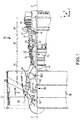
FIG. 1 illustrates a cross-sectional view of an exemplary gas turbine engine, in accordance with various embodiments; -
FIG. 2A illustrates a perspective cross-sectional view of an airfoil, in accordance with various embodiments; -
FIG. 2B illustrates a schematic view of an airfoil fixed within a workpiece space of a robotic assembly, in accordance with various embodiments; -
FIG. 3 is a schematic flowchart diagram of a method of manufacturing an airfoil, in accordance with various embodiments; -
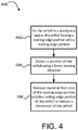
FIG. 4 is a schematic flowchart diagram of another method of manufacturing an airfoil, in accordance with various embodiments; -
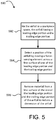
FIG. 5 is a schematic flowchart diagram of yet another method of manufacturing an airfoil, in accordance with various embodiments; -
FIG. 6 illustrates a cross-sectional view, including a magnified cross-sectional view, of an airfoil, in accordance with various embodiments; and -
FIG. 7 illustrates a cross-sectional view, including a magnified cross-sectional view, of an airfoil, in accordance with various embodiments. - The subject matter of the present disclosure is particularly pointed out and distinctly claimed in the concluding portion of the specification. A more complete understanding of the present disclosure, however, may best be obtained by referring to the detailed description and claims when considered in connection with the drawing figures, wherein like numerals denote like elements.
- The detailed description of exemplary embodiments herein makes reference to the accompanying drawings, which show exemplary embodiments by way of illustration. While these exemplary embodiments are described in sufficient detail to enable those skilled in the art to practice the disclosure, it should be understood that other embodiments may be realized and that logical changes and adaptations in design and construction may be made in accordance with this disclosure and the teachings herein without departing from the spirit and scope of the disclosure. Thus, the detailed description herein is presented for purposes of illustration only and not of limitation.
- In various embodiments and with reference to
FIG. 1 , agas turbine engine 20 is provided.Gas turbine engine 20 may be a two-spool turbofan that generally incorporates afan section 22, acompressor section 24, acombustor section 26 and aturbine section 28. Alternative engines may include, for example, an augmentor section among other systems or features. In operation,fan section 22 can drive coolant (e.g., air) along a bypass flow-path B whilecompressor section 24 can drive coolant along a core flow-path C for compression and communication intocombustor section 26 then expansion throughturbine section 28. Although depicted as a turbofangas turbine engine 20 herein, it should be understood that the concepts described herein are not limited to use with turbofans as the teachings may be applied to other types of turbine engines including three-spool architectures. -
Gas turbine engine 20 may generally comprise alow speed spool 30 and ahigh speed spool 32 mounted for rotation about an engine central longitudinal axis A-A' relative to an enginestatic structure 36 or engine case viaseveral bearing systems 38, 38-1, and 38-2. Engine central longitudinal axis A-A' is oriented in the z direction on the provided xyz axis. It should be understood that various bearingsystems 38 at various locations may alternatively or additionally be provided, including for example, bearingsystem 38, bearing system 38-1, and bearing system 38-2. -
Low speed spool 30 may generally comprise aninner shaft 40 that interconnects afan 42, alow pressure compressor 44 and alow pressure turbine 46.Inner shaft 40 may be connected to fan 42 through a gearedarchitecture 48 that can drivefan 42 at a lower speed thanlow speed spool 30.Geared architecture 48 may comprise agear assembly 60 enclosed within agear housing 62.Gear assembly 60 couplesinner shaft 40 to a rotating fan structure.High speed spool 32 may comprise anouter shaft 50 that interconnects ahigh pressure compressor 52 andhigh pressure turbine 54. Acombustor 56 may be located betweenhigh pressure compressor 52 andhigh pressure turbine 54. Amid-turbine frame 57 of enginestatic structure 36 may be located generally betweenhigh pressure turbine 54 andlow pressure turbine 46.Mid-turbine frame 57 may support one ormore bearing systems 38 inturbine section 28.Inner shaft 40 andouter shaft 50 may be concentric and rotate via bearingsystems 38 about the engine central longitudinal axis A-A', which is collinear with their longitudinal axes. As used herein, a "high pressure" compressor or turbine experiences a higher pressure than a corresponding "low pressure" compressor or turbine. - The core airflow C may be compressed by
low pressure compressor 44 thenhigh pressure compressor 52, mixed and burned with fuel incombustor 56, then expanded overhigh pressure turbine 54 andlow pressure turbine 46.Turbines low speed spool 30 andhigh speed spool 32 in response to the expansion. - In various embodiments, geared
architecture 48 may be an epicyclic gear train, such as a star gear system (sun gear in meshing engagement with a plurality of star gears supported by a carrier and in meshing engagement with a ring gear) or other gear system.Geared architecture 48 may have a gear reduction ratio of greater than about 2.3 andlow pressure turbine 46 may have a pressure ratio that is greater than about five (5). In various embodiments, the bypass ratio ofgas turbine engine 20 is greater than about ten (10:1). In various embodiments, the diameter offan 42 may be significantly larger than that of thelow pressure compressor 44, and thelow pressure turbine 46 may have a pressure ratio that is greater than about five (5:1).Low pressure turbine 46 pressure ratio may be measured prior to inlet oflow pressure turbine 46 as related to the pressure at the outlet oflow pressure turbine 46 prior to an exhaust nozzle. It should be understood, however, that the above parameters are exemplary of various embodiments of a suitable geared architecture engine and that the present disclosure contemplates other gas turbine engines including direct drive turbofans. A gas turbine engine may comprise an industrial gas turbine (IGT) or a geared aircraft engine, such as a geared turbofan, or non-geared aircraft engine, such as a turbofan, or may comprise any gas turbine engine as desired. - The
fan section 22, thecompressor section 24 and theturbine section 28 may each comprise rotor systems including blade assemblies having one or more sets of rotating blades, which may rotate about engine central longitudinal axis A-A'. In a gas turbine engine, improving the aerodynamics of flowpath components, such as airfoils, generally leads to more efficient engine performance. Streamlining the shape and dimensions of flowpath components, such as airfoils, decreases the size of the wake downstream of the flowpath components and thus decreases the pressure drag experienced by such components, thereby requiring less energy expenditure for moving internal engine parts. - In various embodiments, an airfoil is disclosed herein. The term "airfoil" refers to rotor components and stator components that are present in the flowpath(s) of the
gas turbine engine 20. That is, in various embodiments the term "airfoil" may refer to rotors such as fan blades, compressor blades, and/or turbine blades. In various embodiments, the term "airfoil" may refer to stators such as fan vanes, compressor vanes, and/or turbine vanes. Accordingly, while numerous details and depictions included herein may be in reference to rotors and/or blades, the scope of the present disclosure is not limited to rotor blades and thus the subject matter of the present disclosure may be applicable to a variety of airfoil flowpath components, both stators and rotors. - With reference to
FIG. 2A , anairfoil 100 having abody 110 is disclosed. Theairfoil 100 may include ahub end 111 for attaching theairfoil 100 to a hub of, for example, a rotor system. Theairfoil 100 may also have a radially outer edge or tip located radially outward from thehub end 111. Theairfoil 100 may have aleading edge 101 opposite a trailingedge 102. In various embodiments, theairfoil 100 may further include a generallyconcave pressure surface 103 and a generallyconvex suction 104 surface joined together at the respectiveleading edge 101 and trailingedge 102. Theairfoil 100 may be curved and twisted relative to, for example, a plane extending radially from the disk, in terms of the overall geometry of theairfoil 100. - It will be noted that airfoils for gas turbine engines may be provided in a variety of sizes, shapes and geometries. Accordingly, the
airfoil 100 of the present disclosure is not limited to the specific geometry, size, and shape shown in the figures. Further, as mentioned above, the disclosedairfoil 100 is not necessarily limited to theturbine section 28 of agas turbine engine 20, but instead may be implemented in other sections of thegas turbine engine 20 and/or may be adapted for use in other types of jet engines, propellers, rotors, stators, etc. - In various embodiments, the
body 110 of theairfoil 100 may be fabricated from a metallic material, such as a metal and/or a metal alloy. In various embodiments, for example, thebody 110 of theairfoil 100 may be fabricated from aluminum, an aluminum alloy, titanium, a titanium alloy, and/or a nickel chromium alloy, monolithic ceramic, or ceramic matrix composites, among other suitable materials. - As mentioned above, the aerodynamics of the
airfoil 100 may contribute to the efficiency of thegas turbine engine 20. Accordingly, manufacturing theairfoil 100 to have desired a shape and desired dimensions may improve operation of thegas turbine engine 20. In various embodiments, and with reference toFIG. 6 , the dimension, shape, and thickness of a leading edge portion 106 (a section of theairfoil 100 proximate the leading edge 101) and a trailing edge portion 107 (a section of theairfoil 100 proximate the trailing edge 102) may be particularly influential on the overall aerodynamic performance of theairfoil 100. For example, the thickness of the trailingedge portion 107 of theairfoil 100 is generally proportional to the size of the wake located downstream of the trailingedge 102 and thus contributes to the magnitude of the pressure drag experienced by theairfoil 100. Additionally, the shape and/or geometry of the trailingedge portion 107 as it transitions/tapers to the trailingedge 102 also contributes to the magnitude of the pressure drag exerted on theairfoil 100. For example, if a trailing edge portion has an abrupt transition to the trailing edge or if the trailing edge were blunt, the fluid (e.g., air, gas) flowing around the airfoil would separate from the surface of the airfoil, creating a low-pressure region (i.e., a "wake") that would create pressure drag. - In various embodiments, and with reference to
FIGS. 2B and3 , the present disclosure provides amethod 390 for manufacturing theairfoil 100 to improve its aerodynamic properties. Themethod 390 includes steps for streamlining the shape and geometry of theairfoil 100 after it has been cast, according to various embodiments. As mentioned above, due to cost, labor, and/or time constraints, it may be impractical, using conventional methods, to cast or otherwise form an airfoil having the desired geometry and dimensions. It may also be impractical, using conventional methods, to improve the aerodynamic properties of a conventional airfoil. - The
method 390 includes, according to various embodiments, fixing theairfoil 100 in a workpiece space 82 (step 392). Theworkpiece space 82 is defined herein as the working area of arobotic assembly 80. That is, the airfoil is mounted in a fixed manner in workable proximity to arobotic assembly 80 or other computer controlled machining assembly. Themethod 390, according to various embodiments, further includes detecting the position of theairfoil 100 in theworkpiece space 82 using a force-sensing element 84 (step 394). In various embodiments,step 394 includes utilizing a force-sensingelement 84 attached to arobotic assembly 80 that perceives the airfoil to determine the relative position of theairfoil 100 with respect to the robotic assembly 80 (e.g., with respect to the workable volume/space of the robotic 80 assembly). - With the relative position of the
airfoil 100 known, themethod 390 further includes, according to various embodiments, removing material from theairfoil 100 to reduce a dimension of the airfoil 100 (step 396). In various embodiments,step 396 includes utilizing a cutting, milling, plasma, or laser tool, among others, that is attached to the same robotic assembly 80 (or at least a robotic assembly that has access to the detected relative position of theairfoil 100 and is calibrated to the workpiece space 82) to remove material from theairfoil 100. In various embodiments,step 396 may include utilizing a diamond cutting device to remove material from theairfoil 100. In various embodiments, the material removed may be material from thebody 110 of theairfoil 100 and/or the material removed may be a coating material that was applied over the surface(s) of theairfoil 100. - In various embodiments,
step 394 includes moving the force-sensingelement 84 across a first surface of theairfoil 100, thereby determining a geometry and the position of the first surface of theairfoil 100. Accordingly,step 396, according to various embodiments, may include removing material from a second surface of theairfoil 100, the second surface being different than the first surface. In various embodiments, as described in greater detail below, the second surface may be opposite (e.g., a suction side is opposite a pressure side of an airfoil) the first surface. That is, according to various embodiments, the step of removing material from the airfoil (step 396) may include removing material from a surface of the airfoil that has not been perceived (.e.g., touched/engaged) by the force-sensingelement 84 duringstep 394. - In various embodiments, the steps of determining the position of the airfoil 100 (step 394) and removing material from the airfoil (step 396) may be performed substantially simultaneously. In various embodiments, for example, the force-sensing
element 84 may have a clamping structure that includes a sensing portion and a cutting portion. The cutting portion of the clamping structure of the force-sensingelement 84 may remove material from the second surface of theairfoil 100 as the sensing portion of clamping structure of the force-sensingelement 84 moves along and follows the first surface of the airfoil. - Disclosed herein with reference to
FIG. 4 in conjunction withFIGS. 6 and7 is anothermethod 490 of manufacturing theairfoil 100, according to various embodiments. Themethod 490 includessteps FIG. 3 . Accordingly, themethod 490 includes fixing theairfoil 100 in theworkpiece space 82. Theairfoil 100, with reference toFIG. 6 , includes aleading edge 101, aleading edge portion 106, a trailingedge 102, and a trailingedge portion 107, according to various embodiments. As briefly described above, the leadingedge portion 106 is the section of theairfoil 100 that is in proximity to and/or that immediately surrounds theleading edge 101 of theairfoil 100 and the trailingedge portion 107 is the section of theairfoil 100 that is in proximity to and/or that immediately surrounds the trailingedge 102 of the airfoil. - The
method 490 further includes, according to various embodiments, detecting the position of the airfoil in theworkpiece space 82 using the force-sensing element 84 (step 494). This detectingstep 494 may include moving the force-sensingelement 84, via an automated scan managed by therobotic assembly 80, across a surface of the either theleading edge portion 106 or the trailingedge portion 107, according to various embodiments. That is, in various embodiments, the surface across which the force-sensingelement 84 moves to determine the position of the airfoil may be theleading edge portion 106 of thepressure side 103 of theairfoil 100, the leadingedge portion 106 of thesuction side 104 of theairfoil 100, the trailingedge portion 107 of thepressure side 103 of theairfoil 100, or the trailingedge portion 107 of thesuction side 104 of theairfoil 100. In various embodiments,step 494 may include moving the force-sensingelement 84 across a plurality of the above mentioned surfaces. - The
method 490 may further include removing material from the leading edge portion 106 (thepressure side 103, thesuction side 104, or both) and/or the trailing edge portion 107 (thepressure side 103, thesuction side 104, or both) to reduce a dimension of theairfoil 100. In various embodiments, and with reference toFIG. 6 , the trailingedge portion 107 of theairfoil 100 is shown with a material to be removed 105. That is,step 496 of themethod 490 may include utilizing a cutting tool that is attached to and moved by arobotic assembly 80 to cut away at thepressure side 103 of the trailingedge portion 107 to removematerial 105, thereby changing the dimension of the trailingedge portion 107 from afirst thickness 108 to asecond thickness 109 that is less than thefirst thickness 108.FIG. 7 illustrates how the trailingedge portion 107 of theairfoil 100 looks after removal of thematerial 105 viastep 496. - The amount of material removed 105 and the relative size, orientation, geometry, and shape of the trailing
edge portion 107 of theairfoil 100 shown inFIGS. 6 and7 is exaggerated, according to various embodiments, in order to clearly depict the results of themethod 490. Thus, the scope of the present disclosure is not to be limited by the relative size of the features shown/depicted in the figures. In various embodiments, step 496 of themethod 490 includes reducing the dimension of the airfoil by between about 25% and about 75%. For example, the first thickness 108 (i.e., pre-removal step) of the trailingedge portion 107 of theairfoil 100 may be about 0.020 inches (0.051 centimeters) and the second thickness 109 (i.e., post-removal step) of theairfoil 100 may be between about 0.015 inches (0.038 centimeters) and about 0.005 inches (0.013 centimeters). In various embodiments, step 496 of themethod 490 includes reducing the dimension of the airfoil by about 50%. For example, the first thickness 108 (i.e., pre-removal step) of the trailingedge portion 107 of theairfoil 100 may be about 0.020 inches (0.051 centimeters) and the second thickness 109 (i.e., post-removal step) of theairfoil 100 may be about 0.010 inches (0.025 centimeters). - In various embodiments, the
step 496 of themethod 490 may include, in addition to removing material (e.g., material 105) from theleading edge portion 106 or the trailing edge portion 107 (or both), blending theleading edge portion 106 and/or the trailingedge portion 107 to transition to the geometry of thepressure side 103 or thesuction side 104 of the airfoil. That is, in various embodiments thestep 496 of themethod 490 includes smoothing a transition between theleading edge portion 106 and/or the trailingedge portion 107 to thepressure side 103 of thesuction side 104 of theairfoil 100. In various embodiments, themethod 490, or at least step 496 of themethod 490, may be performed when the trailing edge portion of the airfoil is uncooled. In various embodiments, theairfoil 100 may be internally convectively cooled and/or may have film holes upstream of the trailing edge 102 (e.g., in the trailing edge portion 107) of theairfoil 100. - In various embodiments, and with reference to
FIG. 5 , anothermethod 590 for manufacturing theairfoil 100 is disclosed. Themethod 590 includes, according to various embodiments, fixing the airfoil in aworkpiece space 82, the airfoil having a leading edge, a leading edge portion, a trailing edge, a trailing edge portion, a suction side, and a pressure side (step 592). Themethod 590 may further include detecting a position of the airfoil in theworkpiece space 82 by moving a force-sensingelement 84 across a first surface of one of the leading edge portion and the trailing edge portion of the airfoil (step 594). Themethod 590 may also include removing material from a second surface, opposite the first surface, of the one of the leading edge portion and the trailing edge portion of the airfoil to reduce a dimension of the one of the leading edge portion and the trailing edge portion of the airfoil and to blend a transition from one of the pressure side and the suction side of the airfoil to the second surface (step 596). - As used herein, "aft" refers to the direction associated with the exhaust (e.g., the back end) of a gas turbine engine. As used herein, "forward" refers to the direction associated with the intake (e.g., the front end) of a gas turbine engine.
- A first component that is "axially outward" of a second component means that a first component is positioned at a greater distance in the aft or forward direction away from the longitudinal center of the gas turbine along the longitudinal axis of the gas turbine, than the second component. A first component that is "axially inward" of a second component means that the first component is positioned closer to the longitudinal center of the gas turbine along the longitudinal axis of the gas turbine, than the second component.
- A first component that is "radially outward" of a second component means that the first component is positioned at a greater distance away from the engine central longitudinal axis than the second component. A first component that is "radially inward" of a second component means that the first component is positioned closer to the engine central longitudinal axis than the second component. In the case of components that rotate circumferentially about the engine central longitudinal axis, a first component that is radially inward of a second component rotates through a circumferentially shorter path than the second component. The terminology "radially outward" and "radially inward" may also be used relative to references other than the engine central longitudinal axis. For example, a first component of a combustor that is radially inward or radially outward of a second component of a combustor is positioned relative to the central longitudinal axis of the combustor.
- Benefits, other advantages, and solutions to problems have been described herein with regard to specific embodiments. Furthermore, the connecting lines shown in the various figures contained herein are intended to represent exemplary functional relationships and/or physical couplings between the various elements. It should be noted that many alternative or additional functional relationships or physical connections may be present in a practical system. However, the benefits, advantages, solutions to problems, and any elements that may cause any benefit, advantage, or solution to occur or become more pronounced are not to be construed as critical, required, or essential features or elements of the disclosure.
- The scope of the disclosure is accordingly to be limited by nothing other than the appended claims, in which reference to an element in the singular is not intended to mean "one and only one" unless explicitly so stated, but rather "one or more." It is to be understood that unless specifically stated otherwise, references to "a," "an," and/or "the" may include one or more than one and that reference to an item in the singular may also include the item in the plural. All ranges and ratio limits disclosed herein may be combined.
- Moreover, where a phrase similar to "at least one of A, B, and C" is used in the claims, it is intended that the phrase be interpreted to mean that A alone may be present in an embodiment, B alone may be present in an embodiment, C alone may be present in an embodiment, or that any combination of the elements A, B and C may be present in a single embodiment; for example, A and B, A and C, B and C, or A and B and C. Different cross-hatching is used throughout the figures to denote different parts but not necessarily to denote the same or different materials.
- The steps recited in any of the method or process descriptions may be executed in any order and are not necessarily limited to the order presented. Furthermore, any reference to singular includes plural embodiments, and any reference to more than one component or step may include a singular embodiment or step. Elements and steps in the figures are illustrated for simplicity and clarity and have not necessarily been rendered according to any particular sequence. For example, steps that may be performed concurrently or in different order are illustrated in the figures to help to improve understanding of embodiments of the present disclosure.
- Any reference to attached, fixed, connected or the like may include permanent, removable, temporary, partial, full and/or any other possible attachment option. Additionally, any reference to without contact (or similar phrases) may also include reduced contact or minimal contact. Surface shading lines may be used throughout the figures to denote different parts or areas but not necessarily to denote the same or different materials. In some cases, reference coordinates may be specific to each figure.
- Systems, methods and apparatus are provided herein. In the detailed description herein, references to "one embodiment", "an embodiment", "various embodiments", etc., indicate that the embodiment described may include a particular feature, structure, or characteristic, but every embodiment may not necessarily include the particular feature, structure, or characteristic. Moreover, such phrases are not necessarily referring to the same embodiment. Further, when a particular feature, structure, or characteristic is described in connection with an embodiment, it is submitted that it is within the knowledge of one skilled in the art to affect such feature, structure, or characteristic in connection with other embodiments whether or not explicitly described. After reading the description, it will be apparent to one skilled in the relevant art(s) how to implement the disclosure in alternative embodiments.
- Furthermore, no element, component, or method step in the present disclosure is intended to be dedicated to the public regardless of whether the element, component, or method step is explicitly recited in the claims. No claim element is intended to invoke 35 U.S.C. 112(f) unless the element is expressly recited using the phrase "means for." As used herein, the terms "comprises", "comprising", or any other variation thereof, are intended to cover a non-exclusive inclusion, such that a process, method, article, or apparatus that comprises a list of elements does not include only those elements but may include other elements not expressly listed or inherent to such process, method, article, or apparatus.
Claims (15)
- A method of manufacturing an airfoil of a gas turbine engine, the method comprising:fixing the airfoil in a workpiece space;detecting a position of the airfoil in the workpiece space using a force-sensing element; andremoving material from the airfoil to reduce a dimension of the airfoil.
- The method of claim 1, wherein detecting the position of the airfoil comprises moving the force-sensing element across a surface of the airfoil.
- The method of claim 2, wherein the surface of the airfoil is a first surface, wherein removing material from the airfoil to reduce the dimension of the airfoil comprises removing material from a second surface of the airfoil opposite the first surface.
- The method of claim 3, wherein removing material from the second surface of the airfoil is performed without moving the force-sensing element across the second surface of the airfoil, or wherein removing material from the second surface of the airfoil is performed substantially simultaneously as moving the force-sensing element across the first surface of the airfoil by using a clamp force-sensing element having a sensing portion and a cutting portion.
- The method of any preceding claim, wherein removing material from the airfoil to reduce a thickness of the airfoil comprises utilizing a diamond cutter to cut away material.
- A method of manufacturing an airfoil of a gas turbine engine, the method comprising:fixing the airfoil in a workpiece space, the airfoil having a leading edge, a leading edge portion, a trailing edge, and a trailing edge portion;detecting a position of the airfoil in the workpiece space using a force-sensing element; andremoving material from at least one of the leading edge portion and the trailing edge portion of the airfoil to reduce a dimension of the one of the leading edge portion and the trailing edge portion.
- The method of claim 6, wherein detecting the position of the airfoil comprises moving the force-sensing element across a surface of the one of the leading edge portion and the trailing edge portion.
- The method of claim 7, wherein the surface is a first surface, wherein removing material from the at least one of the leading edge portion and the trailing edge portion of the airfoil comprises removing material from a second surface of the one of the leading edge portion and the trailing edge portion of the airfoil, the second surface being opposite the first surface.
- The method of claim 8, wherein removing material from the second surface is performed without moving the force-sensing element across the second surface of the at least one of the leading edge portion and the trailing edge portion of the airfoil, and/or wherein optionally, the dimension is a thickness of the one of the leading edge portion and the trailing edge portion between the first surface and the second surface.
- The method of claim 8, wherein removing material from the second surface of the at least one of the leading edge portion and the trailing edge portion of the airfoil comprises blending a transition from a pressure side of the airfoil to the second surface, and/or wherein optionally, removing material from the second surface of the at least one of the leading edge portion and the trailing edge portion of the airfoil comprises blending a transition from a suction side of the airfoil to the second surface.
- The method of any of claims 6 to 10, wherein removing material from the at least one of the leading edge portion and the trailing edge portion of the airfoil comprises utilizing a diamond cutter to cut away material.
- The method of any of claims 6 to 11, further comprising casting the airfoil from raw materials to form the leading edge, the leading edge portion, the trailing edge, and the trailing edge portion.
- The method of any of claims 6 to 12, wherein removing material from at least one of the leading edge portion and the trailing edge portion of the airfoil comprises removing body material of the airfoil.
- The method of any of claims 6 to 12, wherein removing material from at least one of the leading edge portion and the trailing edge portion of the airfoil comprises removing coating material of the airfoil, and/or wherein optionally, removing material from the at least one of the leading edge portion and the trailing edge portion of the airfoil comprises reducing the dimension by between about 25% and about 75%, and/or wherein optionally, removing material from the one of the leading edge portion and the trailing edge portion of the airfoil is performed while the trailing edge portion of the airfoil is uncooled.
- A method of manufacturing an airfoil of a gas turbine engine, the method comprising:fixing the airfoil in a workpiece space, the airfoil having a leading edge, a leading edge portion, a trailing edge, a trailing edge portion, a suction side, and a pressure side;detecting a position of the airfoil in the workpiece space by moving a force-sensing element across a first surface of one of the leading edge portion and the trailing edge portion of the airfoil; andremoving material from a second surface, opposite the first surface, of the one of the leading edge portion and the trailing edge portion of the airfoil to reduce a dimension of the one of the leading edge portion and the trailing edge portion of the airfoil and to blend a transition from one of the pressure side and the suction side of the airfoil to the second surface.
Applications Claiming Priority (1)
| Application Number | Priority Date | Filing Date | Title |
|---|---|---|---|
| US15/289,801 US10399189B2 (en) | 2016-10-10 | 2016-10-10 | Airfoil aerodynamics |
Publications (2)
| Publication Number | Publication Date |
|---|---|
| EP3305466A1 true EP3305466A1 (en) | 2018-04-11 |
| EP3305466B1 EP3305466B1 (en) | 2020-01-08 |
Family
ID=59974203
Family Applications (1)
| Application Number | Title | Priority Date | Filing Date |
|---|---|---|---|
| EP17193398.9A Active EP3305466B1 (en) | 2016-10-10 | 2017-09-27 | Method of manufacturing an airfoil with a thin trailing edge |
Country Status (2)
| Country | Link |
|---|---|
| US (2) | US10399189B2 (en) |
| EP (1) | EP3305466B1 (en) |
Families Citing this family (2)
| Publication number | Priority date | Publication date | Assignee | Title |
|---|---|---|---|---|
| US11066942B2 (en) * | 2019-05-13 | 2021-07-20 | Rolls-Royce Plc | Systems and method for determining turbine assembly flow characteristics |
| US20220100919A1 (en) * | 2020-09-30 | 2022-03-31 | General Electric Company | Probabilistic fatigue and blend limit assessment and visualization methods for airfoils |
Citations (4)
| Publication number | Priority date | Publication date | Assignee | Title |
|---|---|---|---|---|
| EP0453391A2 (en) * | 1990-04-20 | 1991-10-23 | United Technologies Corporation | Method for machining airfoils |
| US20020091459A1 (en) * | 2000-11-10 | 2002-07-11 | Reinhold Meier | Method for reconditioning blades |
| US20150081074A1 (en) * | 2012-04-24 | 2015-03-19 | Snecma | Method for machining the trailing edge of a turbine engine blade |
| US20150361799A1 (en) * | 2014-06-16 | 2015-12-17 | United Technologies Corporation | Method for creating a film cooled article for a gas turbine engine |
Family Cites Families (4)
| Publication number | Priority date | Publication date | Assignee | Title |
|---|---|---|---|---|
| JP2008019484A (en) * | 2006-07-13 | 2008-01-31 | Chuo Motor Wheel Co Ltd | Metal composite and method for producing metal composite |
| EP2623229B1 (en) * | 2010-09-27 | 2019-09-11 | Hitachi Metals, Ltd. | Manufacturing method for blade material |
| US20130318787A1 (en) * | 2012-06-05 | 2013-12-05 | Seth J. Thomen | Manufacturing a family of airfoils |
| US20140075754A1 (en) * | 2012-09-18 | 2014-03-20 | United Technologies Corporation | System method for machining aircraft components |
-
2016
- 2016-10-10 US US15/289,801 patent/US10399189B2/en active Active
-
2017
- 2017-09-27 EP EP17193398.9A patent/EP3305466B1/en active Active
-
2019
- 2019-11-08 US US16/678,622 patent/US20200316731A1/en not_active Abandoned
Patent Citations (4)
| Publication number | Priority date | Publication date | Assignee | Title |
|---|---|---|---|---|
| EP0453391A2 (en) * | 1990-04-20 | 1991-10-23 | United Technologies Corporation | Method for machining airfoils |
| US20020091459A1 (en) * | 2000-11-10 | 2002-07-11 | Reinhold Meier | Method for reconditioning blades |
| US20150081074A1 (en) * | 2012-04-24 | 2015-03-19 | Snecma | Method for machining the trailing edge of a turbine engine blade |
| US20150361799A1 (en) * | 2014-06-16 | 2015-12-17 | United Technologies Corporation | Method for creating a film cooled article for a gas turbine engine |
Non-Patent Citations (1)
| Title |
|---|
| BREMER C: "KOMPRESSOR-UND TURBINENSCHAUFELN AUTOMATISCH REPARIEREN", WERKSTATT + BETRIEB, CARL HANSER VERLAG, MÜNCHEN DE, vol. 129, no. 7/08, 1 August 1996 (1996-08-01), pages 672 - 674, XP000678763, ISSN: 0043-2792 * |
Also Published As
| Publication number | Publication date |
|---|---|
| US10399189B2 (en) | 2019-09-03 |
| EP3305466B1 (en) | 2020-01-08 |
| US20200316731A1 (en) | 2020-10-08 |
| US20180099362A1 (en) | 2018-04-12 |
Similar Documents
| Publication | Publication Date | Title |
|---|---|---|
| US11193496B2 (en) | Gas turbine engine airfoil | |
| EP2543867B1 (en) | Efficient, low pressure ratio propulsor for gas turbine engines | |
| US10590775B2 (en) | Gas turbine engine airfoil | |
| EP3231994A1 (en) | Compressor secondary flow aft cone cooling scheme | |
| US11041396B2 (en) | Axial-radial cooling slots on inner air seal | |
| EP3043026A2 (en) | Gas turbine component, airfoil component and corresponding method of vectoring cooling air | |
| US10280759B2 (en) | Mechanically retained fan blade cover | |
| US12535007B2 (en) | Cover plate connections for a hollow fan blade | |
| US20190337102A1 (en) | Interlocking Stage of Airfoils | |
| US10526905B2 (en) | Asymmetric vane assembly | |
| EP3108119B1 (en) | Turbofan engine with geared architecture and lpc blade airfoils | |
| EP3305466B1 (en) | Method of manufacturing an airfoil with a thin trailing edge | |
| US20190323359A1 (en) | Blade and a method of manufacturing a blade | |
| EP3108102A1 (en) | Gas turbine engine airfoil | |
| EP3287603B1 (en) | Chamfered stator vane rail | |
| US11098604B2 (en) | Radial-axial cooling slots | |
| US10605259B2 (en) | Gas turbine engine airfoil | |
| EP3299587B1 (en) | Gas turbine engine airfoil | |
| US20200291806A1 (en) | Boas and methods of making a boas having fatigue resistant cooling inlets | |
| EP3293361A1 (en) | Fluid flow assembly, gas turbine engine and corresponding method of manufacturing |
Legal Events
| Date | Code | Title | Description |
|---|---|---|---|
| PUAI | Public reference made under article 153(3) epc to a published international application that has entered the european phase |
Free format text: ORIGINAL CODE: 0009012 |
|
| STAA | Information on the status of an ep patent application or granted ep patent |
Free format text: STATUS: THE APPLICATION HAS BEEN PUBLISHED |
|
| AK | Designated contracting states |
Kind code of ref document: A1 Designated state(s): AL AT BE BG CH CY CZ DE DK EE ES FI FR GB GR HR HU IE IS IT LI LT LU LV MC MK MT NL NO PL PT RO RS SE SI SK SM TR |
|
| AX | Request for extension of the european patent |
Extension state: BA ME |
|
| STAA | Information on the status of an ep patent application or granted ep patent |
Free format text: STATUS: REQUEST FOR EXAMINATION WAS MADE |
|
| 17P | Request for examination filed |
Effective date: 20181011 |
|
| RBV | Designated contracting states (corrected) |
Designated state(s): AL AT BE BG CH CY CZ DE DK EE ES FI FR GB GR HR HU IE IS IT LI LT LU LV MC MK MT NL NO PL PT RO RS SE SI SK SM TR |
|
| GRAP | Despatch of communication of intention to grant a patent |
Free format text: ORIGINAL CODE: EPIDOSNIGR1 |
|
| STAA | Information on the status of an ep patent application or granted ep patent |
Free format text: STATUS: GRANT OF PATENT IS INTENDED |
|
| RIC1 | Information provided on ipc code assigned before grant |
Ipc: F01D 5/14 20060101ALI20190711BHEP Ipc: B23P 15/02 20060101AFI20190711BHEP Ipc: F01D 5/00 20060101ALI20190711BHEP |
|
| INTG | Intention to grant announced |
Effective date: 20190801 |
|
| GRAS | Grant fee paid |
Free format text: ORIGINAL CODE: EPIDOSNIGR3 |
|
| GRAA | (expected) grant |
Free format text: ORIGINAL CODE: 0009210 |
|
| STAA | Information on the status of an ep patent application or granted ep patent |
Free format text: STATUS: THE PATENT HAS BEEN GRANTED |
|
| AK | Designated contracting states |
Kind code of ref document: B1 Designated state(s): AL AT BE BG CH CY CZ DE DK EE ES FI FR GB GR HR HU IE IS IT LI LT LU LV MC MK MT NL NO PL PT RO RS SE SI SK SM TR |
|
| REG | Reference to a national code |
Ref country code: GB Ref legal event code: FG4D |
|
| REG | Reference to a national code |
Ref country code: CH Ref legal event code: EP |
|
| REG | Reference to a national code |
Ref country code: DE Ref legal event code: R096 Ref document number: 602017010601 Country of ref document: DE |
|
| REG | Reference to a national code |
Ref country code: IE Ref legal event code: FG4D |
|
| REG | Reference to a national code |
Ref country code: AT Ref legal event code: REF Ref document number: 1222099 Country of ref document: AT Kind code of ref document: T Effective date: 20200215 |
|
| REG | Reference to a national code |
Ref country code: NL Ref legal event code: MP Effective date: 20200108 |
|
| REG | Reference to a national code |
Ref country code: LT Ref legal event code: MG4D |
|
| PG25 | Lapsed in a contracting state [announced via postgrant information from national office to epo] |
Ref country code: NL Free format text: LAPSE BECAUSE OF FAILURE TO SUBMIT A TRANSLATION OF THE DESCRIPTION OR TO PAY THE FEE WITHIN THE PRESCRIBED TIME-LIMIT Effective date: 20200108 Ref country code: PT Free format text: LAPSE BECAUSE OF FAILURE TO SUBMIT A TRANSLATION OF THE DESCRIPTION OR TO PAY THE FEE WITHIN THE PRESCRIBED TIME-LIMIT Effective date: 20200531 Ref country code: FI Free format text: LAPSE BECAUSE OF FAILURE TO SUBMIT A TRANSLATION OF THE DESCRIPTION OR TO PAY THE FEE WITHIN THE PRESCRIBED TIME-LIMIT Effective date: 20200108 Ref country code: RS Free format text: LAPSE BECAUSE OF FAILURE TO SUBMIT A TRANSLATION OF THE DESCRIPTION OR TO PAY THE FEE WITHIN THE PRESCRIBED TIME-LIMIT Effective date: 20200108 Ref country code: NO Free format text: LAPSE BECAUSE OF FAILURE TO SUBMIT A TRANSLATION OF THE DESCRIPTION OR TO PAY THE FEE WITHIN THE PRESCRIBED TIME-LIMIT Effective date: 20200408 Ref country code: LT Free format text: LAPSE BECAUSE OF FAILURE TO SUBMIT A TRANSLATION OF THE DESCRIPTION OR TO PAY THE FEE WITHIN THE PRESCRIBED TIME-LIMIT Effective date: 20200108 |
|
| PG25 | Lapsed in a contracting state [announced via postgrant information from national office to epo] |
Ref country code: SE Free format text: LAPSE BECAUSE OF FAILURE TO SUBMIT A TRANSLATION OF THE DESCRIPTION OR TO PAY THE FEE WITHIN THE PRESCRIBED TIME-LIMIT Effective date: 20200108 Ref country code: LV Free format text: LAPSE BECAUSE OF FAILURE TO SUBMIT A TRANSLATION OF THE DESCRIPTION OR TO PAY THE FEE WITHIN THE PRESCRIBED TIME-LIMIT Effective date: 20200108 Ref country code: BG Free format text: LAPSE BECAUSE OF FAILURE TO SUBMIT A TRANSLATION OF THE DESCRIPTION OR TO PAY THE FEE WITHIN THE PRESCRIBED TIME-LIMIT Effective date: 20200408 Ref country code: IS Free format text: LAPSE BECAUSE OF FAILURE TO SUBMIT A TRANSLATION OF THE DESCRIPTION OR TO PAY THE FEE WITHIN THE PRESCRIBED TIME-LIMIT Effective date: 20200508 Ref country code: GR Free format text: LAPSE BECAUSE OF FAILURE TO SUBMIT A TRANSLATION OF THE DESCRIPTION OR TO PAY THE FEE WITHIN THE PRESCRIBED TIME-LIMIT Effective date: 20200409 Ref country code: HR Free format text: LAPSE BECAUSE OF FAILURE TO SUBMIT A TRANSLATION OF THE DESCRIPTION OR TO PAY THE FEE WITHIN THE PRESCRIBED TIME-LIMIT Effective date: 20200108 |
|
| REG | Reference to a national code |
Ref country code: DE Ref legal event code: R097 Ref document number: 602017010601 Country of ref document: DE |
|
| PG25 | Lapsed in a contracting state [announced via postgrant information from national office to epo] |
Ref country code: SM Free format text: LAPSE BECAUSE OF FAILURE TO SUBMIT A TRANSLATION OF THE DESCRIPTION OR TO PAY THE FEE WITHIN THE PRESCRIBED TIME-LIMIT Effective date: 20200108 Ref country code: SK Free format text: LAPSE BECAUSE OF FAILURE TO SUBMIT A TRANSLATION OF THE DESCRIPTION OR TO PAY THE FEE WITHIN THE PRESCRIBED TIME-LIMIT Effective date: 20200108 Ref country code: ES Free format text: LAPSE BECAUSE OF FAILURE TO SUBMIT A TRANSLATION OF THE DESCRIPTION OR TO PAY THE FEE WITHIN THE PRESCRIBED TIME-LIMIT Effective date: 20200108 Ref country code: DK Free format text: LAPSE BECAUSE OF FAILURE TO SUBMIT A TRANSLATION OF THE DESCRIPTION OR TO PAY THE FEE WITHIN THE PRESCRIBED TIME-LIMIT Effective date: 20200108 Ref country code: CZ Free format text: LAPSE BECAUSE OF FAILURE TO SUBMIT A TRANSLATION OF THE DESCRIPTION OR TO PAY THE FEE WITHIN THE PRESCRIBED TIME-LIMIT Effective date: 20200108 Ref country code: EE Free format text: LAPSE BECAUSE OF FAILURE TO SUBMIT A TRANSLATION OF THE DESCRIPTION OR TO PAY THE FEE WITHIN THE PRESCRIBED TIME-LIMIT Effective date: 20200108 Ref country code: RO Free format text: LAPSE BECAUSE OF FAILURE TO SUBMIT A TRANSLATION OF THE DESCRIPTION OR TO PAY THE FEE WITHIN THE PRESCRIBED TIME-LIMIT Effective date: 20200108 |
|
| PLBE | No opposition filed within time limit |
Free format text: ORIGINAL CODE: 0009261 |
|
| STAA | Information on the status of an ep patent application or granted ep patent |
Free format text: STATUS: NO OPPOSITION FILED WITHIN TIME LIMIT |
|
| REG | Reference to a national code |
Ref country code: AT Ref legal event code: MK05 Ref document number: 1222099 Country of ref document: AT Kind code of ref document: T Effective date: 20200108 |
|
| 26N | No opposition filed |
Effective date: 20201009 |
|
| PG25 | Lapsed in a contracting state [announced via postgrant information from national office to epo] |
Ref country code: AT Free format text: LAPSE BECAUSE OF FAILURE TO SUBMIT A TRANSLATION OF THE DESCRIPTION OR TO PAY THE FEE WITHIN THE PRESCRIBED TIME-LIMIT Effective date: 20200108 Ref country code: IT Free format text: LAPSE BECAUSE OF FAILURE TO SUBMIT A TRANSLATION OF THE DESCRIPTION OR TO PAY THE FEE WITHIN THE PRESCRIBED TIME-LIMIT Effective date: 20200108 |
|
| PG25 | Lapsed in a contracting state [announced via postgrant information from national office to epo] |
Ref country code: SI Free format text: LAPSE BECAUSE OF FAILURE TO SUBMIT A TRANSLATION OF THE DESCRIPTION OR TO PAY THE FEE WITHIN THE PRESCRIBED TIME-LIMIT Effective date: 20200108 Ref country code: PL Free format text: LAPSE BECAUSE OF FAILURE TO SUBMIT A TRANSLATION OF THE DESCRIPTION OR TO PAY THE FEE WITHIN THE PRESCRIBED TIME-LIMIT Effective date: 20200108 |
|
| REG | Reference to a national code |
Ref country code: CH Ref legal event code: PL |
|
| REG | Reference to a national code |
Ref country code: BE Ref legal event code: MM Effective date: 20200930 |
|
| PG25 | Lapsed in a contracting state [announced via postgrant information from national office to epo] |
Ref country code: LU Free format text: LAPSE BECAUSE OF NON-PAYMENT OF DUE FEES Effective date: 20200927 |
|
| PG25 | Lapsed in a contracting state [announced via postgrant information from national office to epo] |
Ref country code: LI Free format text: LAPSE BECAUSE OF NON-PAYMENT OF DUE FEES Effective date: 20200930 Ref country code: IE Free format text: LAPSE BECAUSE OF NON-PAYMENT OF DUE FEES Effective date: 20200927 Ref country code: CH Free format text: LAPSE BECAUSE OF NON-PAYMENT OF DUE FEES Effective date: 20200930 Ref country code: BE Free format text: LAPSE BECAUSE OF NON-PAYMENT OF DUE FEES Effective date: 20200930 |
|
| PG25 | Lapsed in a contracting state [announced via postgrant information from national office to epo] |
Ref country code: TR Free format text: LAPSE BECAUSE OF FAILURE TO SUBMIT A TRANSLATION OF THE DESCRIPTION OR TO PAY THE FEE WITHIN THE PRESCRIBED TIME-LIMIT Effective date: 20200108 Ref country code: MT Free format text: LAPSE BECAUSE OF FAILURE TO SUBMIT A TRANSLATION OF THE DESCRIPTION OR TO PAY THE FEE WITHIN THE PRESCRIBED TIME-LIMIT Effective date: 20200108 Ref country code: CY Free format text: LAPSE BECAUSE OF FAILURE TO SUBMIT A TRANSLATION OF THE DESCRIPTION OR TO PAY THE FEE WITHIN THE PRESCRIBED TIME-LIMIT Effective date: 20200108 |
|
| PG25 | Lapsed in a contracting state [announced via postgrant information from national office to epo] |
Ref country code: MK Free format text: LAPSE BECAUSE OF FAILURE TO SUBMIT A TRANSLATION OF THE DESCRIPTION OR TO PAY THE FEE WITHIN THE PRESCRIBED TIME-LIMIT Effective date: 20200108 Ref country code: MC Free format text: LAPSE BECAUSE OF FAILURE TO SUBMIT A TRANSLATION OF THE DESCRIPTION OR TO PAY THE FEE WITHIN THE PRESCRIBED TIME-LIMIT Effective date: 20200108 Ref country code: AL Free format text: LAPSE BECAUSE OF FAILURE TO SUBMIT A TRANSLATION OF THE DESCRIPTION OR TO PAY THE FEE WITHIN THE PRESCRIBED TIME-LIMIT Effective date: 20200108 |
|
| REG | Reference to a national code |
Ref country code: DE Ref legal event code: R081 Ref document number: 602017010601 Country of ref document: DE Owner name: RAYTHEON TECHNOLOGIES CORPORATION (N.D.GES.D.S, US Free format text: FORMER OWNER: UNITED TECHNOLOGIES CORPORATION, FARMINGTON, CONN., US Ref country code: DE Ref legal event code: R081 Ref document number: 602017010601 Country of ref document: DE Owner name: RTX CORPORATION (N.D.GES.D. STAATES DELAWARE),, US Free format text: FORMER OWNER: UNITED TECHNOLOGIES CORPORATION, FARMINGTON, CONN., US |
|
| P01 | Opt-out of the competence of the unified patent court (upc) registered |
Effective date: 20230520 |
|
| PGFP | Annual fee paid to national office [announced via postgrant information from national office to epo] |
Ref country code: DE Payment date: 20250820 Year of fee payment: 9 |
|
| PGFP | Annual fee paid to national office [announced via postgrant information from national office to epo] |
Ref country code: GB Payment date: 20250822 Year of fee payment: 9 |
|
| PGFP | Annual fee paid to national office [announced via postgrant information from national office to epo] |
Ref country code: FR Payment date: 20250821 Year of fee payment: 9 |
|
| REG | Reference to a national code |
Ref country code: DE Ref legal event code: R081 Ref document number: 602017010601 Country of ref document: DE Owner name: RTX CORPORATION (N.D.GES.D. STAATES DELAWARE),, US Free format text: FORMER OWNER: RAYTHEON TECHNOLOGIES CORPORATION (N.D.GES.D.STAATES DELAWARE), ARLINGTON, VA, US |