EP3305457A1 - Machine tool - Google Patents
Machine tool Download PDFInfo
- Publication number
- EP3305457A1 EP3305457A1 EP15894106.2A EP15894106A EP3305457A1 EP 3305457 A1 EP3305457 A1 EP 3305457A1 EP 15894106 A EP15894106 A EP 15894106A EP 3305457 A1 EP3305457 A1 EP 3305457A1
- Authority
- EP
- European Patent Office
- Prior art keywords
- pump
- nozzle
- liquid
- machine tool
- workpiece
- Prior art date
- Legal status (The legal status is an assumption and is not a legal conclusion. Google has not performed a legal analysis and makes no representation as to the accuracy of the status listed.)
- Granted
Links
Images

Classifications
-
- B—PERFORMING OPERATIONS; TRANSPORTING
- B23—MACHINE TOOLS; METAL-WORKING NOT OTHERWISE PROVIDED FOR
- B23K—SOLDERING OR UNSOLDERING; WELDING; CLADDING OR PLATING BY SOLDERING OR WELDING; CUTTING BY APPLYING HEAT LOCALLY, e.g. FLAME CUTTING; WORKING BY LASER BEAM
- B23K26/00—Working by laser beam, e.g. welding, cutting or boring
- B23K26/14—Working by laser beam, e.g. welding, cutting or boring using a fluid stream, e.g. a jet of gas, in conjunction with the laser beam; Nozzles therefor
- B23K26/146—Working by laser beam, e.g. welding, cutting or boring using a fluid stream, e.g. a jet of gas, in conjunction with the laser beam; Nozzles therefor the fluid stream containing a liquid
-
- B—PERFORMING OPERATIONS; TRANSPORTING
- B23—MACHINE TOOLS; METAL-WORKING NOT OTHERWISE PROVIDED FOR
- B23K—SOLDERING OR UNSOLDERING; WELDING; CLADDING OR PLATING BY SOLDERING OR WELDING; CUTTING BY APPLYING HEAT LOCALLY, e.g. FLAME CUTTING; WORKING BY LASER BEAM
- B23K26/00—Working by laser beam, e.g. welding, cutting or boring
- B23K26/70—Auxiliary operations or equipment
- B23K26/702—Auxiliary equipment
-
- F—MECHANICAL ENGINEERING; LIGHTING; HEATING; WEAPONS; BLASTING
- F16—ENGINEERING ELEMENTS AND UNITS; GENERAL MEASURES FOR PRODUCING AND MAINTAINING EFFECTIVE FUNCTIONING OF MACHINES OR INSTALLATIONS; THERMAL INSULATION IN GENERAL
- F16L—PIPES; JOINTS OR FITTINGS FOR PIPES; SUPPORTS FOR PIPES, CABLES OR PROTECTIVE TUBING; MEANS FOR THERMAL INSULATION IN GENERAL
- F16L55/00—Devices or appurtenances for use in, or in connection with, pipes or pipe systems
- F16L55/04—Devices damping pulsations or vibrations in fluids
Definitions
- the present invention relates to a machine tool that performs machining, while ejecting a pressurized liquid toward a workpiece, and reduces the pressure pulsations in the liquid.
- Patent Literature 1 describes a hybrid laser processing method, comprising a pump that pumps a high-pressure liquid, an accumulator for storing the liquid transferred from the pump and for discharging the stored liquid, and a processing head for forming the liquid into a columnar shape and spraying the liquid toward a workpiece, as well as for irradiating the workpiece with laser light having passed through the columnar liquid, wherein the processing head and the workpiece are moved relative to each other so as to perform the required processing on the workpiece.
- Patent Literature 1 JP-A-2007-098418
- the technical task of the present invention is to solve such problems of the prior art, and an object of the present invention is to provide a machine tool for performing processing while ejecting a pressurized liquid toward a workpiece, wherein pressure pulsations of the pressurized liquid ejected toward the workpiece are reduced or eliminated without the use of a pressurized gas such as from an accumulator.
- a machine tool for processing a workpiece while ejecting a pressurized liquid comprising a pump configured to pressurize the liquid, a nozzle configured to eject the liquid pressurized by the pump toward the workpiece, and a pulsation removing pipe provided between a discharge port of the pump and the nozzle, the pulsation removing pipe is formed with a pile wound a plurality of turns or bent zigzagged a plurality of times is provided.
- a pulsation removing pipe is provided between the pump and the nozzle.
- FIG. 1 shows an optical head of a laser processing machine as an example of a machine tool to which the present invention is applicable.
- an optical head 10 includes a laser irradiation head 16 which is arranged in a housing 12, receives laser light from a laser oscillator 14 via a light guide member 14a, such as an optical fiber, and which irradiates the light onto a collimation lens 18.
- the laser light from the laser irradiation head 16 is collimated by the collimation lens 18, and is reflected by a first mirror 20 toward a second mirror 22, and is reflected by the second mirror 22 toward a focus lens 24.
- the laser light focused by the focus lens 24 is irradiated to the outside of the housing 12 through the nozzle head 26.
- the optical axis of the laser beam irradiated by the optical head 10 is substantially parallel to the Z-axis.
- the first and second mirrors 20, 22 have planar reflecting surfaces, and have motors 20a, 22a as mirror orientation adjusting means for adjusting the directions of the reflecting surfaces (the directions perpendicular to the reflecting surfaces) and adjusting the direction of the laser beam irradiated from the optical head 10.
- the first and second mirrors 20, 22, in particular the second mirror 22 which reflects the laser light toward the focus lens 24, include a dielectric multilayer film which is adapted to the wavelength of the laser light emitted from the laser oscillator 14, reflects the laser light of the adaptable wavelength, and allows light of wavelengths other than the adaptable wavelength to be transmitted therethrough. More specifically, such dielectric multilayer film is formed by vapor deposition on a glass plate.
- the nozzle head 26 is a hollow member that receives a supply of water from a water supply device 40 via a supply line 28.
- a nozzle 26b for ejecting a water jet is provided on the bottom wall of the nozzle head 26 facing the table 36, and a window 26a, which is made of a transparent member such as glass, is provided on the upper surface of the nozzle facing the focus lens 24 on the opposite side of the bottom wall.
- the nozzle 26b is communicable with the outside of the housing 12 through an aperture formed in the bottom surface of the housing 12 of the optical head 10.
- a table 34 of the laser processing machine is arranged on the underside of the housing 12, and a workpiece W is fixed to the table 34 via a fixture 36 so as to face the nozzle 26b.
- the water supply device 40 is equipped with a tank 42 for storing liquids, in particular water, a pump 44 for pressurizing the water of the tank 42 and supplying the water to the optical head 10, a pressure regulating valve 46 provided in the supply line 28, and a pulsation removing pipe 50 provided in the discharge line 48 of the pump 44.
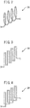
- the pulsation removing pipe 50 can be, for example, in the form of a spiral wound a plurality of times, as shown in FIG. 2 , in the form consisting of straight pipe portions and bent pipe portions alternately and repeatedly arranged, as shown in FIG. 3 , or in the form consisting of straight pipe portions and bent pipe portions alternately and repeatedly wound a plurality of times, as shown in FIG. 4 .
- the pulsation removing pipe 50 may be formed by an elastically deformable hose.
- the liquid stored in the tank 42 is pressurized by the pump 44, sent to the pressure regulating valve 46 via the discharge line 48 and the pulsation removing pipe 50, and after the pressure thereof is reduced to a predetermined pressure required by the laser processing by the pressure regulating valve 46, the liquid is ejected from the nozzle 26a of the nozzle head 26 in the shape of a water column 30 toward the workpiece W via the supply line 28.
- the liquid to be supplied to the nozzle head 26 must be pressurized to a high pressure, such as, for example, 100 MPa, and a high-pressure pump, such as a double-headed piston pump, is used as the pump 44.
- a high-pressure pump such as a double-headed piston pump
- the pressure of the liquid discharged from the pump 44 fluctuates or pulsates in synch with the operation of the pistons.
- the pulsation removing pipe 50 is disposed between the pump 44 and the nozzle 26b, more preferably, between the pump 44 and the pressure regulating valve 46, so that the length of the line from the pump 44 to the nozzle 26b is lengthened and the volume of the line from the pump 44 to the nozzle 26b is increases, whereby pressure pulsations in the liquid supplied to the nozzle 26b are eliminated. Furthermore, by forming the pulsation removing pipe 50 from a high-pressure elastic hose, the pulsation removing effect can be further enhanced.
Landscapes
- Engineering & Computer Science (AREA)
- Mechanical Engineering (AREA)
- Physics & Mathematics (AREA)
- Optics & Photonics (AREA)
- General Engineering & Computer Science (AREA)
- Plasma & Fusion (AREA)
- Laser Beam Processing (AREA)
Abstract
Description
- The present invention relates to a machine tool that performs machining, while ejecting a pressurized liquid toward a workpiece, and reduces the pressure pulsations in the liquid.
- Patent Literature 1 describes a hybrid laser processing method, comprising a pump that pumps a high-pressure liquid, an accumulator for storing the liquid transferred from the pump and for discharging the stored liquid, and a processing head for forming the liquid into a columnar shape and spraying the liquid toward a workpiece, as well as for irradiating the workpiece with laser light having passed through the columnar liquid, wherein the processing head and the workpiece are moved relative to each other so as to perform the required processing on the workpiece.
- Patent Literature 1:
JP-A-2007-098418 - However, since extremely high-pressure water is supplied to the laser processing machine as described in Patent Document 1, the gas pressure of the accumulator is also high. Thus, for example, when transporting the laser processing machine from the manufacturing facility to a factory of the user by aircraft, it is necessary to remove the high-pressure gas from the accumulator prior to transportation and after the laser processing machine is installed in the factory of the user, it is necessary to refill the accumulator with high-pressure gas. Therefore, an increase in the cost is required for installation of the laser processing machine.
- The technical task of the present invention is to solve such problems of the prior art, and an object of the present invention is to provide a machine tool for performing processing while ejecting a pressurized liquid toward a workpiece, wherein pressure pulsations of the pressurized liquid ejected toward the workpiece are reduced or eliminated without the use of a pressurized gas such as from an accumulator.
- In order to achieve the above object, according to the present invention, a machine tool for processing a workpiece while ejecting a pressurized liquid, comprising a pump configured to pressurize the liquid, a nozzle configured to eject the liquid pressurized by the pump toward the workpiece, and a pulsation removing pipe provided between a discharge port of the pump and the nozzle, the pulsation removing pipe is formed with a pile wound a plurality of turns or bent zigzagged a plurality of times is provided.
- According to the present invention, a pulsation removing pipe is provided between the pump and the nozzle. By increasing the length of the pipe from the pump to the nozzle, and by increasing the volume of the pipe from the pump to the nozzle, pressure pulsations of the liquid supplied to the nozzle are reduced or eliminated.
-
-
Figure 1 is a schematic cross-sectional view of an optical head of a laser processing machine as an example of a machine tool to which the present invention is applied. -
Figure 2 is a schematic view showing the pulsation removing pipe in a form which is spirally wound a plurality of turns. -
Figure 3 is a schematic view showing the pulsation removing pipe in a form in which straight pipe portions and bent pipe portions are alternately and repeatedly arranged. -
Figure 4 is a schematic view showing the pulsation removing pipe in a form in which straight pipe portions and bent pipe portions are alternately and repeatedly wound a plurality of turns. -
FIG. 1 shows an optical head of a laser processing machine as an example of a machine tool to which the present invention is applicable. InFIG. 1 , anoptical head 10 includes alaser irradiation head 16 which is arranged in ahousing 12, receives laser light from alaser oscillator 14 via alight guide member 14a, such as an optical fiber, and which irradiates the light onto acollimation lens 18. The laser light from thelaser irradiation head 16 is collimated by thecollimation lens 18, and is reflected by afirst mirror 20 toward asecond mirror 22, and is reflected by thesecond mirror 22 toward afocus lens 24. The laser light focused by thefocus lens 24 is irradiated to the outside of thehousing 12 through thenozzle head 26. Here, the optical axis of the laser beam irradiated by theoptical head 10 is substantially parallel to the Z-axis. - The first and
second mirrors motors 20a, 22a as mirror orientation adjusting means for adjusting the directions of the reflecting surfaces (the directions perpendicular to the reflecting surfaces) and adjusting the direction of the laser beam irradiated from theoptical head 10. Furthermore, the first andsecond mirrors second mirror 22 which reflects the laser light toward thefocus lens 24, include a dielectric multilayer film which is adapted to the wavelength of the laser light emitted from thelaser oscillator 14, reflects the laser light of the adaptable wavelength, and allows light of wavelengths other than the adaptable wavelength to be transmitted therethrough. More specifically, such dielectric multilayer film is formed by vapor deposition on a glass plate. By forming thesecond mirror 22 from the dielectric multilayer film, it is possible to monitor the positional relationship between the laser beam irradiated from thenozzle 26b and thenozzle 26b using thecamera 32. - The
nozzle head 26 is a hollow member that receives a supply of water from awater supply device 40 via asupply line 28. Anozzle 26b for ejecting a water jet is provided on the bottom wall of thenozzle head 26 facing the table 36, and awindow 26a, which is made of a transparent member such as glass, is provided on the upper surface of the nozzle facing thefocus lens 24 on the opposite side of the bottom wall. Thenozzle 26b is communicable with the outside of thehousing 12 through an aperture formed in the bottom surface of thehousing 12 of theoptical head 10. A table 34 of the laser processing machine is arranged on the underside of thehousing 12, and a workpiece W is fixed to the table 34 via afixture 36 so as to face thenozzle 26b. - The
water supply device 40 is equipped with atank 42 for storing liquids, in particular water, apump 44 for pressurizing the water of thetank 42 and supplying the water to theoptical head 10, apressure regulating valve 46 provided in thesupply line 28, and apulsation removing pipe 50 provided in thedischarge line 48 of thepump 44. Thepulsation removing pipe 50 can be, for example, in the form of a spiral wound a plurality of times, as shown inFIG. 2 , in the form consisting of straight pipe portions and bent pipe portions alternately and repeatedly arranged, as shown inFIG. 3 , or in the form consisting of straight pipe portions and bent pipe portions alternately and repeatedly wound a plurality of times, as shown inFIG. 4 . Furthermore, thepulsation removing pipe 50 may be formed by an elastically deformable hose. - Thus, the liquid stored in the
tank 42 is pressurized by thepump 44, sent to thepressure regulating valve 46 via thedischarge line 48 and thepulsation removing pipe 50, and after the pressure thereof is reduced to a predetermined pressure required by the laser processing by thepressure regulating valve 46, the liquid is ejected from thenozzle 26a of thenozzle head 26 in the shape of awater column 30 toward the workpiece W via thesupply line 28. - In the laser processing machine, in general, it is necessary to stably eject a
water column 30 having a diameter of 1 mm or less toward the workpiece W. Thus, the liquid to be supplied to thenozzle head 26 must be pressurized to a high pressure, such as, for example, 100 MPa, and a high-pressure pump, such as a double-headed piston pump, is used as thepump 44. As a result, the pressure of the liquid discharged from thepump 44 fluctuates or pulsates in synch with the operation of the pistons. When the pressure of the liquid supplied to theoptical head 10 of the laser processing machine pulsates, astable water column 30 cannot be formed, and the laser beam irradiated toward the workpiece W through thewater column 30 is also unstable. - In the present invention, the
pulsation removing pipe 50 is disposed between thepump 44 and thenozzle 26b, more preferably, between thepump 44 and thepressure regulating valve 46, so that the length of the line from thepump 44 to thenozzle 26b is lengthened and the volume of the line from thepump 44 to thenozzle 26b is increases, whereby pressure pulsations in the liquid supplied to thenozzle 26b are eliminated. Furthermore, by forming thepulsation removing pipe 50 from a high-pressure elastic hose, the pulsation removing effect can be further enhanced. -
- 10
- optical head
- 26
- nozzle head
- 26b
- nozzle
- 28
- supply line
- 30
- water column
- 40
- water supply device
- 42
- tank
- 44
- pump
- 46
- pressure regulating valve
- 48
- discharge line
- 50
- pulsation removing pipe
Claims (3)
- A machine tool for processing a workpiece while ejecting a pressurized liquid, comprising:a pump configured to pressurize the liquid;a nozzle configured to eject the liquid pressurized by the pump toward the workpiece; anda pulsation removing pipe provided between a discharge port of the pump and the nozzle, the pulsation removing pipe is formed with a pile wound a plurality of turns or bent zigzagged a plurality of times.
- The machine tool according to claim 1, wherein the machine tool is a laser processing machine and the nozzle ejects the liquid pressurized by the pump along an optical axis of a laser beam.
- The machine tool according to claim 1 or 2, wherein the pulsation removing pipe is formed by an elastically deformable hose.
Applications Claiming Priority (1)
| Application Number | Priority Date | Filing Date | Title |
|---|---|---|---|
| PCT/JP2015/065649 WO2016194071A1 (en) | 2015-05-29 | 2015-05-29 | Machine tool |
Publications (3)
| Publication Number | Publication Date |
|---|---|
| EP3305457A1 true EP3305457A1 (en) | 2018-04-11 |
| EP3305457A4 EP3305457A4 (en) | 2019-03-06 |
| EP3305457B1 EP3305457B1 (en) | 2020-07-22 |
Family
ID=57440313
Family Applications (1)
| Application Number | Title | Priority Date | Filing Date |
|---|---|---|---|
| EP15894106.2A Active EP3305457B1 (en) | 2015-05-29 | 2015-05-29 | Machine tool |
Country Status (4)
| Country | Link |
|---|---|
| US (1) | US10675710B2 (en) |
| EP (1) | EP3305457B1 (en) |
| JP (1) | JP6490206B2 (en) |
| WO (1) | WO2016194071A1 (en) |
Families Citing this family (5)
| Publication number | Priority date | Publication date | Assignee | Title |
|---|---|---|---|---|
| EP3466597A1 (en) * | 2017-10-05 | 2019-04-10 | Synova S.A. | Apparatus for machining a workpiece with a laser beam |
| JP2019069465A (en) * | 2017-10-11 | 2019-05-09 | 株式会社ディスコ | Laser processing device |
| JP7511902B2 (en) * | 2019-02-13 | 2024-07-08 | 大学共同利用機関法人自然科学研究機構 | Laser processing device and laser processing method |
| JP6884184B2 (en) * | 2019-09-25 | 2021-06-09 | 株式会社牧野フライス製作所 | Water jet laser machine |
| CN116393820A (en) * | 2023-05-12 | 2023-07-07 | 浙江工业大学 | A water-conducting laser coupling device |
Family Cites Families (14)
| Publication number | Priority date | Publication date | Assignee | Title |
|---|---|---|---|---|
| US3503804A (en) * | 1967-04-25 | 1970-03-31 | Hellmut Schneider | Method and apparatus for the production of sonic or ultrasonic waves on a surface |
| US3780208A (en) * | 1972-06-05 | 1973-12-18 | Moore & Co Samuel | Composite hose having a grounding wire enclosed in a sleeve and wrapped about the core tube of the hose |
| JPS5826032Y2 (en) * | 1978-04-06 | 1983-06-04 | 旭大隈産業株式会社 | Airless spray paint pumping device |
| JPS54148665A (en) | 1978-05-13 | 1979-11-21 | Akira Adachi | Storage device for closet |
| US4561251A (en) * | 1982-05-04 | 1985-12-31 | Les Produits Associes Lpa Sa | Hydraulic apparatus |
| JPS6396392A (en) * | 1986-10-14 | 1988-04-27 | 日立電線株式会社 | Piping for power steering equipment |
| JPH1075956A (en) * | 1996-09-02 | 1998-03-24 | Fuji Photo Optical Co Ltd | Deaerated water supply device |
| EP2154369B1 (en) * | 2003-05-15 | 2013-01-02 | LG Electronics Inc. | Compressor with suction muffler |
| JP4457933B2 (en) * | 2005-03-18 | 2010-04-28 | 澁谷工業株式会社 | Hybrid laser processing equipment |
| JP4844715B2 (en) * | 2005-08-25 | 2011-12-28 | 澁谷工業株式会社 | Hybrid laser processing equipment |
| JP4715432B2 (en) * | 2005-09-30 | 2011-07-06 | 澁谷工業株式会社 | Hybrid laser processing method and apparatus |
| JP2008136913A (en) * | 2006-11-30 | 2008-06-19 | Optrex Corp | Cleaning apparatus |
| JP4325679B2 (en) * | 2007-02-08 | 2009-09-02 | 株式会社デンソー | Manufacturing method of mold for forming honeycomb structure |
| US8366667B2 (en) * | 2010-02-11 | 2013-02-05 | Baxter International Inc. | Flow pulsatility dampening devices |
-
2015
- 2015-05-29 US US15/577,937 patent/US10675710B2/en active Active
- 2015-05-29 WO PCT/JP2015/065649 patent/WO2016194071A1/en not_active Ceased
- 2015-05-29 JP JP2017521337A patent/JP6490206B2/en active Active
- 2015-05-29 EP EP15894106.2A patent/EP3305457B1/en active Active
Also Published As
| Publication number | Publication date |
|---|---|
| EP3305457A4 (en) | 2019-03-06 |
| WO2016194071A1 (en) | 2016-12-08 |
| EP3305457B1 (en) | 2020-07-22 |
| US10675710B2 (en) | 2020-06-09 |
| JP6490206B2 (en) | 2019-03-27 |
| JPWO2016194071A1 (en) | 2017-11-24 |
| US20180161930A1 (en) | 2018-06-14 |
Similar Documents
| Publication | Publication Date | Title |
|---|---|---|
| US10675710B2 (en) | Machine tool | |
| KR102360003B1 (en) | Apparatus for supplying treatment liquid, method of supplying treatment liquid and storage medium | |
| US9782791B2 (en) | High frequency uniform droplet maker and method | |
| WO2006100798A1 (en) | Hybrid laser processing system | |
| CN101247919B (en) | Laser compound processing device | |
| WO2007010783A1 (en) | Hybrid laser processing device | |
| US8581220B2 (en) | Target supply apparatus, control system, control apparatus and control circuit thereof | |
| JP3871240B2 (en) | Hybrid processing equipment | |
| CN107457482A (en) | A kind of array type optical waveguide liquid jet device and method | |
| EP2517818A1 (en) | Cutting apparatus for fiber-reinforced resin | |
| US10251253B2 (en) | Extreme ultraviolet light generation device | |
| JP2007029980A (en) | Hybrid laser beam machining apparatus | |
| WO2017145969A1 (en) | Liquid material discharge device comprising booster circuit | |
| JP2019177399A (en) | Laser processing device, pressurizing vessel and laser processing method | |
| JP2006255769A (en) | Hybrid laser processing equipment | |
| JP2017131907A (en) | Laser processing head, laser processing system and laser processing method | |
| US11911849B2 (en) | Laser peening processing apparatus and laser peening processing method | |
| JP2012066269A (en) | Laser beam machining apparatus | |
| JP4715432B2 (en) | Hybrid laser processing method and apparatus | |
| US12377494B2 (en) | Water jet laser processing machine | |
| JP4123390B2 (en) | Hybrid machining apparatus and hybrid machining method | |
| JP2017209709A (en) | Laser peening device | |
| JP5501100B2 (en) | Laser processing equipment | |
| CN102233483B (en) | Equipment and method for processing nozzle body | |
| US20160285229A1 (en) | Laser Assembly |
Legal Events
| Date | Code | Title | Description |
|---|---|---|---|
| STAA | Information on the status of an ep patent application or granted ep patent |
Free format text: STATUS: THE INTERNATIONAL PUBLICATION HAS BEEN MADE |
|
| PUAI | Public reference made under article 153(3) epc to a published international application that has entered the european phase |
Free format text: ORIGINAL CODE: 0009012 |
|
| STAA | Information on the status of an ep patent application or granted ep patent |
Free format text: STATUS: REQUEST FOR EXAMINATION WAS MADE |
|
| 17P | Request for examination filed |
Effective date: 20171123 |
|
| AK | Designated contracting states |
Kind code of ref document: A1 Designated state(s): AL AT BE BG CH CY CZ DE DK EE ES FI FR GB GR HR HU IE IS IT LI LT LU LV MC MK MT NL NO PL PT RO RS SE SI SK SM TR |
|
| AX | Request for extension of the european patent |
Extension state: BA ME |
|
| DAV | Request for validation of the european patent (deleted) | ||
| DAX | Request for extension of the european patent (deleted) | ||
| A4 | Supplementary search report drawn up and despatched |
Effective date: 20190201 |
|
| RIC1 | Information provided on ipc code assigned before grant |
Ipc: B23K 26/146 20140101AFI20190128BHEP Ipc: B23K 26/70 20140101ALI20190128BHEP |
|
| GRAP | Despatch of communication of intention to grant a patent |
Free format text: ORIGINAL CODE: EPIDOSNIGR1 |
|
| STAA | Information on the status of an ep patent application or granted ep patent |
Free format text: STATUS: GRANT OF PATENT IS INTENDED |
|
| RIC1 | Information provided on ipc code assigned before grant |
Ipc: B23K 26/70 20140101ALI20200113BHEP Ipc: B23K 26/146 20140101AFI20200113BHEP |
|
| INTG | Intention to grant announced |
Effective date: 20200211 |
|
| GRAS | Grant fee paid |
Free format text: ORIGINAL CODE: EPIDOSNIGR3 |
|
| GRAA | (expected) grant |
Free format text: ORIGINAL CODE: 0009210 |
|
| STAA | Information on the status of an ep patent application or granted ep patent |
Free format text: STATUS: THE PATENT HAS BEEN GRANTED |
|
| AK | Designated contracting states |
Kind code of ref document: B1 Designated state(s): AL AT BE BG CH CY CZ DE DK EE ES FI FR GB GR HR HU IE IS IT LI LT LU LV MC MK MT NL NO PL PT RO RS SE SI SK SM TR |
|
| REG | Reference to a national code |
Ref country code: GB Ref legal event code: FG4D |
|
| REG | Reference to a national code |
Ref country code: CH Ref legal event code: EP Ref country code: CH Ref legal event code: NV Representative=s name: BUGNION S.A., CH |
|
| REG | Reference to a national code |
Ref country code: DE Ref legal event code: R096 Ref document number: 602015056356 Country of ref document: DE |
|
| REG | Reference to a national code |
Ref country code: AT Ref legal event code: REF Ref document number: 1292957 Country of ref document: AT Kind code of ref document: T Effective date: 20200815 |
|
| REG | Reference to a national code |
Ref country code: IE Ref legal event code: FG4D |
|
| REG | Reference to a national code |
Ref country code: LT Ref legal event code: MG4D |
|
| REG | Reference to a national code |
Ref country code: AT Ref legal event code: MK05 Ref document number: 1292957 Country of ref document: AT Kind code of ref document: T Effective date: 20200722 |
|
| PG25 | Lapsed in a contracting state [announced via postgrant information from national office to epo] |
Ref country code: PT Free format text: LAPSE BECAUSE OF FAILURE TO SUBMIT A TRANSLATION OF THE DESCRIPTION OR TO PAY THE FEE WITHIN THE PRESCRIBED TIME-LIMIT Effective date: 20201123 Ref country code: NO Free format text: LAPSE BECAUSE OF FAILURE TO SUBMIT A TRANSLATION OF THE DESCRIPTION OR TO PAY THE FEE WITHIN THE PRESCRIBED TIME-LIMIT Effective date: 20201022 Ref country code: AT Free format text: LAPSE BECAUSE OF FAILURE TO SUBMIT A TRANSLATION OF THE DESCRIPTION OR TO PAY THE FEE WITHIN THE PRESCRIBED TIME-LIMIT Effective date: 20200722 Ref country code: HR Free format text: LAPSE BECAUSE OF FAILURE TO SUBMIT A TRANSLATION OF THE DESCRIPTION OR TO PAY THE FEE WITHIN THE PRESCRIBED TIME-LIMIT Effective date: 20200722 Ref country code: ES Free format text: LAPSE BECAUSE OF FAILURE TO SUBMIT A TRANSLATION OF THE DESCRIPTION OR TO PAY THE FEE WITHIN THE PRESCRIBED TIME-LIMIT Effective date: 20200722 Ref country code: BG Free format text: LAPSE BECAUSE OF FAILURE TO SUBMIT A TRANSLATION OF THE DESCRIPTION OR TO PAY THE FEE WITHIN THE PRESCRIBED TIME-LIMIT Effective date: 20201022 Ref country code: LT Free format text: LAPSE BECAUSE OF FAILURE TO SUBMIT A TRANSLATION OF THE DESCRIPTION OR TO PAY THE FEE WITHIN THE PRESCRIBED TIME-LIMIT Effective date: 20200722 Ref country code: FI Free format text: LAPSE BECAUSE OF FAILURE TO SUBMIT A TRANSLATION OF THE DESCRIPTION OR TO PAY THE FEE WITHIN THE PRESCRIBED TIME-LIMIT Effective date: 20200722 Ref country code: GR Free format text: LAPSE BECAUSE OF FAILURE TO SUBMIT A TRANSLATION OF THE DESCRIPTION OR TO PAY THE FEE WITHIN THE PRESCRIBED TIME-LIMIT Effective date: 20201023 Ref country code: SE Free format text: LAPSE BECAUSE OF FAILURE TO SUBMIT A TRANSLATION OF THE DESCRIPTION OR TO PAY THE FEE WITHIN THE PRESCRIBED TIME-LIMIT Effective date: 20200722 |
|
| PG25 | Lapsed in a contracting state [announced via postgrant information from national office to epo] |
Ref country code: LV Free format text: LAPSE BECAUSE OF FAILURE TO SUBMIT A TRANSLATION OF THE DESCRIPTION OR TO PAY THE FEE WITHIN THE PRESCRIBED TIME-LIMIT Effective date: 20200722 Ref country code: RS Free format text: LAPSE BECAUSE OF FAILURE TO SUBMIT A TRANSLATION OF THE DESCRIPTION OR TO PAY THE FEE WITHIN THE PRESCRIBED TIME-LIMIT Effective date: 20200722 Ref country code: PL Free format text: LAPSE BECAUSE OF FAILURE TO SUBMIT A TRANSLATION OF THE DESCRIPTION OR TO PAY THE FEE WITHIN THE PRESCRIBED TIME-LIMIT Effective date: 20200722 Ref country code: IS Free format text: LAPSE BECAUSE OF FAILURE TO SUBMIT A TRANSLATION OF THE DESCRIPTION OR TO PAY THE FEE WITHIN THE PRESCRIBED TIME-LIMIT Effective date: 20201122 |
|
| PG25 | Lapsed in a contracting state [announced via postgrant information from national office to epo] |
Ref country code: NL Free format text: LAPSE BECAUSE OF FAILURE TO SUBMIT A TRANSLATION OF THE DESCRIPTION OR TO PAY THE FEE WITHIN THE PRESCRIBED TIME-LIMIT Effective date: 20200722 |
|
| REG | Reference to a national code |
Ref country code: DE Ref legal event code: R097 Ref document number: 602015056356 Country of ref document: DE |
|
| PG25 | Lapsed in a contracting state [announced via postgrant information from national office to epo] |
Ref country code: RO Free format text: LAPSE BECAUSE OF FAILURE TO SUBMIT A TRANSLATION OF THE DESCRIPTION OR TO PAY THE FEE WITHIN THE PRESCRIBED TIME-LIMIT Effective date: 20200722 Ref country code: SM Free format text: LAPSE BECAUSE OF FAILURE TO SUBMIT A TRANSLATION OF THE DESCRIPTION OR TO PAY THE FEE WITHIN THE PRESCRIBED TIME-LIMIT Effective date: 20200722 Ref country code: EE Free format text: LAPSE BECAUSE OF FAILURE TO SUBMIT A TRANSLATION OF THE DESCRIPTION OR TO PAY THE FEE WITHIN THE PRESCRIBED TIME-LIMIT Effective date: 20200722 Ref country code: DK Free format text: LAPSE BECAUSE OF FAILURE TO SUBMIT A TRANSLATION OF THE DESCRIPTION OR TO PAY THE FEE WITHIN THE PRESCRIBED TIME-LIMIT Effective date: 20200722 Ref country code: CZ Free format text: LAPSE BECAUSE OF FAILURE TO SUBMIT A TRANSLATION OF THE DESCRIPTION OR TO PAY THE FEE WITHIN THE PRESCRIBED TIME-LIMIT Effective date: 20200722 |
|
| PLBE | No opposition filed within time limit |
Free format text: ORIGINAL CODE: 0009261 |
|
| STAA | Information on the status of an ep patent application or granted ep patent |
Free format text: STATUS: NO OPPOSITION FILED WITHIN TIME LIMIT |
|
| PG25 | Lapsed in a contracting state [announced via postgrant information from national office to epo] |
Ref country code: AL Free format text: LAPSE BECAUSE OF FAILURE TO SUBMIT A TRANSLATION OF THE DESCRIPTION OR TO PAY THE FEE WITHIN THE PRESCRIBED TIME-LIMIT Effective date: 20200722 |
|
| 26N | No opposition filed |
Effective date: 20210423 |
|
| PG25 | Lapsed in a contracting state [announced via postgrant information from national office to epo] |
Ref country code: SK Free format text: LAPSE BECAUSE OF FAILURE TO SUBMIT A TRANSLATION OF THE DESCRIPTION OR TO PAY THE FEE WITHIN THE PRESCRIBED TIME-LIMIT Effective date: 20200722 |
|
| PG25 | Lapsed in a contracting state [announced via postgrant information from national office to epo] |
Ref country code: SI Free format text: LAPSE BECAUSE OF FAILURE TO SUBMIT A TRANSLATION OF THE DESCRIPTION OR TO PAY THE FEE WITHIN THE PRESCRIBED TIME-LIMIT Effective date: 20200722 |
|
| REG | Reference to a national code |
Ref country code: NL Ref legal event code: MP Effective date: 20200722 |
|
| PG25 | Lapsed in a contracting state [announced via postgrant information from national office to epo] |
Ref country code: MC Free format text: LAPSE BECAUSE OF FAILURE TO SUBMIT A TRANSLATION OF THE DESCRIPTION OR TO PAY THE FEE WITHIN THE PRESCRIBED TIME-LIMIT Effective date: 20200722 Ref country code: LU Free format text: LAPSE BECAUSE OF NON-PAYMENT OF DUE FEES Effective date: 20210529 |
|
| REG | Reference to a national code |
Ref country code: BE Ref legal event code: MM Effective date: 20210531 |
|
| PG25 | Lapsed in a contracting state [announced via postgrant information from national office to epo] |
Ref country code: IE Free format text: LAPSE BECAUSE OF NON-PAYMENT OF DUE FEES Effective date: 20210529 |
|
| PG25 | Lapsed in a contracting state [announced via postgrant information from national office to epo] |
Ref country code: BE Free format text: LAPSE BECAUSE OF NON-PAYMENT OF DUE FEES Effective date: 20210531 |
|
| PG25 | Lapsed in a contracting state [announced via postgrant information from national office to epo] |
Ref country code: CY Free format text: LAPSE BECAUSE OF FAILURE TO SUBMIT A TRANSLATION OF THE DESCRIPTION OR TO PAY THE FEE WITHIN THE PRESCRIBED TIME-LIMIT Effective date: 20200722 |
|
| PG25 | Lapsed in a contracting state [announced via postgrant information from national office to epo] |
Ref country code: HU Free format text: LAPSE BECAUSE OF FAILURE TO SUBMIT A TRANSLATION OF THE DESCRIPTION OR TO PAY THE FEE WITHIN THE PRESCRIBED TIME-LIMIT; INVALID AB INITIO Effective date: 20150529 |
|
| PG25 | Lapsed in a contracting state [announced via postgrant information from national office to epo] |
Ref country code: MK Free format text: LAPSE BECAUSE OF FAILURE TO SUBMIT A TRANSLATION OF THE DESCRIPTION OR TO PAY THE FEE WITHIN THE PRESCRIBED TIME-LIMIT Effective date: 20200722 |
|
| PG25 | Lapsed in a contracting state [announced via postgrant information from national office to epo] |
Ref country code: TR Free format text: LAPSE BECAUSE OF FAILURE TO SUBMIT A TRANSLATION OF THE DESCRIPTION OR TO PAY THE FEE WITHIN THE PRESCRIBED TIME-LIMIT Effective date: 20200722 |
|
| PG25 | Lapsed in a contracting state [announced via postgrant information from national office to epo] |
Ref country code: MT Free format text: LAPSE BECAUSE OF FAILURE TO SUBMIT A TRANSLATION OF THE DESCRIPTION OR TO PAY THE FEE WITHIN THE PRESCRIBED TIME-LIMIT Effective date: 20200722 |
|
| PGFP | Annual fee paid to national office [announced via postgrant information from national office to epo] |
Ref country code: DE Payment date: 20250402 Year of fee payment: 11 |
|
| PGFP | Annual fee paid to national office [announced via postgrant information from national office to epo] |
Ref country code: IT Payment date: 20250422 Year of fee payment: 11 |
|
| PGFP | Annual fee paid to national office [announced via postgrant information from national office to epo] |
Ref country code: FR Payment date: 20250401 Year of fee payment: 11 |
|
| PGFP | Annual fee paid to national office [announced via postgrant information from national office to epo] |
Ref country code: CH Payment date: 20250601 Year of fee payment: 11 |
|
| PGFP | Annual fee paid to national office [announced via postgrant information from national office to epo] |
Ref country code: GB Payment date: 20260323 Year of fee payment: 12 |