EP3305193A1 - Posture detection device, spectacle-type electronic device, posture detection method, and program - Google Patents
Posture detection device, spectacle-type electronic device, posture detection method, and program Download PDFInfo
- Publication number
- EP3305193A1 EP3305193A1 EP16803018.7A EP16803018A EP3305193A1 EP 3305193 A1 EP3305193 A1 EP 3305193A1 EP 16803018 A EP16803018 A EP 16803018A EP 3305193 A1 EP3305193 A1 EP 3305193A1
- Authority
- EP
- European Patent Office
- Prior art keywords
- posture
- acceleration
- posture detection
- accelerations
- basis
- Prior art date
- Legal status (The legal status is an assumption and is not a legal conclusion. Google has not performed a legal analysis and makes no representation as to the accuracy of the status listed.)
- Withdrawn
Links
Images




Classifications
-
- A—HUMAN NECESSITIES
- A61—MEDICAL OR VETERINARY SCIENCE; HYGIENE
- A61B—DIAGNOSIS; SURGERY; IDENTIFICATION
- A61B5/00—Measuring for diagnostic purposes; Identification of persons
- A61B5/103—Measuring devices for testing the shape, pattern, colour, size or movement of the body or parts thereof, for diagnostic purposes
- A61B5/11—Measuring movement of the entire body or parts thereof, e.g. head or hand tremor or mobility of a limb
- A61B5/1116—Determining posture transitions
-
- A—HUMAN NECESSITIES
- A61—MEDICAL OR VETERINARY SCIENCE; HYGIENE
- A61B—DIAGNOSIS; SURGERY; IDENTIFICATION
- A61B5/00—Measuring for diagnostic purposes; Identification of persons
- A61B5/68—Arrangements of detecting, measuring or recording means, e.g. sensors, in relation to patient
- A61B5/6801—Arrangements of detecting, measuring or recording means, e.g. sensors, in relation to patient specially adapted to be attached to or worn on the body surface
- A61B5/6802—Sensor mounted on worn items
- A61B5/6803—Head-worn items, e.g. helmets, masks, headphones or goggles
-
- A—HUMAN NECESSITIES
- A61—MEDICAL OR VETERINARY SCIENCE; HYGIENE
- A61B—DIAGNOSIS; SURGERY; IDENTIFICATION
- A61B2562/00—Details of sensors; Constructional details of sensor housings or probes; Accessories for sensors
- A61B2562/02—Details of sensors specially adapted for in-vivo measurements
- A61B2562/0219—Inertial sensors, e.g. accelerometers, gyroscopes, tilt switches
Definitions
- the present invention relates to a posture detection apparatus, a glasses-type electronic device, a posture detection method, and a program for detecting the posture of a target such as a portion of a human body.
- the posture of a human body at the time of walking may be a parameter indicating a mental activity state or a physical condition of the human body.
- Such a posture at the time of walking can be determined by, for example, detecting a displacement with respect to the axis of a body at the time of walking.
- the acceleration output from an acceleration sensor is affected by acceleration occurring at the time of walking other than gravity, and thus the posture cannot be determined only using the acceleration, and angular velocity that is not affected by the acceleration is necessary.
- a method for calculating an attitude angle of a rigid body in action a method for calculating an attitude angle by integrating the angular velocity measured by a gyro sensor is widely used.
- the present invention has been made in light of such circumstances, and the object thereof is to provide a posture detection apparatus, a glasses-type electronic device, a posture detection method, and a program that enable detection of the posture of a target using a configuration having lower power consumption, a smaller scale, and lower cost.
- a posture detection apparatus has accumulation means that accumulates, within a predetermined period, a plurality of accelerations corresponding to movements of a portion that is a detection target, the accelerations being detected at predetermined time intervals, and posture detection means that detects a posture of the portion on the basis of the accumulated acceleration.
- information closely analogous to information detected using a gyro sensor can be obtained by accumulating, at the predetermined time intervals, the plurality of accelerations corresponding to the movements of the portion that is the detection target at the accumulation means.
- the posture of the portion can be detected on the basis of the accumulated acceleration at the posture detection means.
- Posture detection can be performed on the basis of only acceleration in this manner, and thus the posture of the target can be detected using a configuration having lower power consumption, a smaller scale, and lower cost.
- the accumulation means of the posture detection apparatus accumulates the accelerations in a plurality of directions on a direction basis, and the posture detection means detects the posture of the predetermined portion on the basis of the accelerations accumulated regarding the plurality of directions.
- the posture of the target can be detected in the plurality of directions.
- the posture detection means of the posture detection apparatus detects an inclination of the portion with respect to a predetermined axis.
- the posture of the portion of the target can be detected as the inclination of the portion with respect to the predetermined axis.
- the posture detection apparatus has step count detection means that detects one step of the human body on the basis of the accelerations, the accumulation means accumulates the accelerations using a period of time corresponding to the one step as the predetermined period, and the posture detection means detects an inclination with respect to the axis of the human body on the basis of a cumulative value of the accelerations within the period of time corresponding to the one step.
- the posture detection apparatus further has acceleration detection means that detects the accelerations.
- the accelerations can be obtained by the acceleration detection means.
- the acceleration detection means of the posture detection apparatus according to the present invention is provided on or near the head of a human body.
- the posture of the human body during exercise can be detected with high accuracy by providing the acceleration detection means on or near the head.
- a glasses-type electronic device is provided with the above-described posture detection apparatus.
- a posture detection method has an accumulation step for accumulating, within a predetermined period, a plurality of accelerations corresponding to movements of a portion that is a detection target, the accelerations being detected at predetermined time intervals, and a posture detection step for detecting a posture of the portion on the basis of the accumulated acceleration.
- a program according to the present invention causes a computer to execute: an accumulation process for accumulating, within a predetermined period, a plurality of accelerations corresponding to movements of a portion that is a detection target, the accelerations being detected at predetermined time intervals, and a posture detection process for detecting a posture of the portion on the basis of the accumulated acceleration.
- a posture detection apparatus a glasses-type electronic device, a posture detection method, and a program that enable detection of the posture of a target using a configuration having lower power consumption, a smaller scale, and lower cost can be provided.
- Fig. 1 is an external perspective view of the glasses 1 according to the embodiment of the present invention.
- Fig. 2 is a functional block diagram of the glasses 1 illustrated in Fig. 1 .
- the glasses 1 have, for example, temples 11 and 13 that can be worn over a user's ears, rims 31 and 33 by which lenses 21 and 23 are fixed, a bridge 35 that is interposed between the rims 31 and 33, and nose pads 41 and 43.
- the tips of the rims 31 and 33 are called temple tips 37 and 39.
- hinges 45 and 47 are provided between the temples 11 and 13 and the rims 31 and 33.
- the temples 11 and 13, the rims 31 and 33, the bridge 35 interposed between the rims 31 and 33, the nose pads 41 and 43, the temple tips 37 and 39, and the hinges 45 and 47 are an example of a glasses-type frame according to the present invention.
- a storage box 51 is provided between the nose pads 41 and 43.
- a storage box 53 is fixed on the side where the temple tip 37 of the temple 11 is provided.
- a right nose electrode 61 is provided on a surface of the nose pad 41, and a left nose electrode 63 is provided on a surface of the nose pad 43.
- the right nose electrode 61 In a state in which the user is wearing the glasses 1, the right nose electrode 61 is in contact with (pressed against) a right side surface with respect to the bridge of the nose of the user, and detects an eye electric potential that is the electric potential of the skin that is in contact.
- the left nose electrode 63 In the state in which the user is wearing the glasses 1, the left nose electrode 63 is in contact with a left side surface with respect to the bridge of the nose of the user, and detects an eye electric potential that is the electric potential of the skin that is in contact.
- the right nose electrode 61 and the left nose electrode 63 are symmetrically placed right and left when the nose of the user is viewed from the front while the user is wearing the glasses 1.
- a glabella electrode 65 that is in contact with the root of the nose or the glabella of the user and detects the electric potential of the skin that is in contact in the state in which the user is wearing the glasses 1.
- the right nose electrode 61, the left nose electrode 63, and the glabella electrode 65 are, for example, made of stainless steel or titanium.
- the right nose electrode 61, the left nose electrode 63, and the glabella electrode 65 are formed in shapes that are appropriate for the shapes of human body portions to be in contact.
- the storage box 53 has a storage space inside thereof, and an acceleration sensor 71, a communication unit 73, a battery 75, and a processing unit 77 are stored in the storage space.
- the storage box 51 and the storage box 53 are electrically connected by wiring such as a printed board.
- the acceleration sensor 71 is an acceleration sensor for three axes: X, Y, and Z, and outputs, for each axis, detected acceleration to the processing unit 77.
- the acceleration sensor 71 detects acceleration at predetermined detection time intervals.
- the acceleration sensor 71 stores the detected acceleration in a memory (not illustrated).
- the acceleration sensor 71 when the user is wearing the glasses 1, the acceleration sensor 71 is positioned near his or her ear of his or her head such that the movement of his or her head is appropriately detected.
- the communication unit 73 performs wireless communication using for example Bluetooth® or a wireless LAN, and can transmit, to an external apparatus, the eye electric potentials input from the right nose electrode 61, the left nose electrode 63, and the glabella electrode 65, the acceleration input from the acceleration sensor 71, and so on. High functional processing using high processing performance and a memory capacity can be realized.
- the processing unit 77 generates information regarding the user on the basis of the eye electric potentials input from the right nose electrode 61, the left nose electrode 63, and the glabella electrode 65, and the acceleration input from the acceleration sensor 71.
- the eye electric potentials (skin potentials) input from the right nose electrode 61, the left nose electrode 63, and the glabella electrode 65, and the acceleration input from the acceleration sensor 71 are electric potentials corresponding to perspiration and movement of the user, and reflect the user's physical condition or mental state.
- the processing circuit 77 can detect the user's physical condition or mental state by comparing the input electric potentials and acceleration of the user with the above-described reference data.
- the cornea side of an eyeball is positively charged, and the retina side is negatively charged.
- the eye electric potential of the right nose electrode 61 with reference to the eye electric potential of the glabella electrode 65, and the eye electric potential of the left nose electrode 63 with reference to the glabella electrode 65 become negative.
- the eye electric potential of the right nose electrode 61 with reference to the glabella electrode 65 becomes negative, and the eye electric potential of the left nose electrode 63 with reference to the glabella electrode 65 becomes positive.
- the eye electric potential of the right nose electrode 61 with reference to the glabella electrode 65 becomes positive, and the eye electric potential of the left nose electrode 63 with reference to the glabella electrode 65 becomes negative.
- the eye electric potential of the glabella electrode 65 with reference to a reference electrode may be subtracted from the eye electric potential of the right nose electrode 61 with reference to the reference electrode.
- the eye electric potential of the glabella electrode 65 with reference to the reference electrode may be subtracted from the eye electric potential of the left nose electrode 63 with reference to the reference electrode.
- a ground electrode may be used as the reference electrode.
- the eye electric potential from the right nose electrode 61 is negative and the eye electric potential from the left nose electrode 63 is positive, it can be detected that the user's line of sight is directed rightward, and in the case where the eye electric potential from the right nose electrode 61 is positive and the eye electric potential from the left nose electrode 63 is negative, it can be detected that the user's line of sight is directed leftward.
- Fig. 3 is a functional block diagram regarding posture detection by the processing unit 77 illustrated in Fig. 2 .
- the processing unit 77 includes, for example, a step count detection unit 951, an acceleration accumulation unit 953, and a posture detection unit 955.
- the functions of the units of the processing unit 77 may be realized by executing programs at a processing circuit, or at least some of the functions may be realized using hardware.
- the step count detection unit 951 detects one step (a step count) on the basis of the acceleration from the acceleration sensor 71, and outputs the detection result to the acceleration accumulation unit 953.
- the step count detection unit 951 detects one step, for example, on the condition that a combined value of three-axis accelerations detected by the acceleration sensor 71 becomes lower than 1G and thereafter becomes higher than 1G.
- the acceleration accumulation unit 953 calculates, within a period of time corresponding to the one step detected by the step count detection unit 951, acceleration cumulative values by accumulating the accelerations detected by the acceleration sensor 71.
- the acceleration accumulation unit 953 integrates, for each axis, acceleration in units of one step, and calculates an acceleration cumulative value (simple posture pitch angle) that is the integral of the acceleration.
- the direction in which his or her head is inclined with respect to the axis of his or her body can be determined on the basis of the acceleration cumulative values, the acceleration sensor 71 being provided for his or her head.
- the acceleration accumulation unit 953 can calculate a roll in addition to a pitch on the basis of the acceleration cumulative value for a predetermined axis.
- the acceleration accumulation unit 953 can determine, on the basis of the direction of acceleration, how the acceleration sensor 71 (his or her head) is inclined.
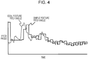
- Fig. 4 is a diagram illustrating a one-axis simple posture pitch angle generated by the glasses 1 illustrated in Fig. 1 and an ideal posture pitch angle generated using a method using a conventional gyro.
- Fig. 5 is a diagram illustrating the relationship between the one-axis simple posture pitch angle and the ideal posture pitch angle illustrated in Fig. 4 .
- the acceleration cumulative value (simple posture pitch angle) generated by the acceleration accumulation unit 953 is closely analogous to the ideal posture pitch angle obtained by using the gyro.
- the simple posture pitch angle can be used instead of the ideal posture pitch angle.
- the posture detection unit 955 detects, on the basis of the acceleration cumulative values calculated by the acceleration accumulation unit 953, the posture of a portion for which the acceleration sensor 71 is provided.
- the posture is an inclination from the axis of his or her body, that is, a pitch angle.
- the posture detection unit 955 detects the inclination of his or her body for every step and determines the left-and-right balance of his or her walking posture.
- his or her age can be determined on the basis of, for example, the displacement and inclination of his or her body. For example, an elderly person has a small displacement.
- a health state of the human can also be checked on the basis of the posture of his or her head by looking at the movement of his or her head.
- the correlation between the displacement and a disease is determined.
- the acceleration sensor 71 is provided for his or her head; however, the acceleration sensor 71 may also be provided for another portion such as a foot of a human body.
- the posture detection unit 955 uses the cumulative values of acceleration within one step and generated by the acceleration accumulation unit 953 in the above-described example, but may also use the mean value of the acceleration.
- Fig. 6 is a flowchart of acceleration detection by the processing unit 77 illustrated in Fig. 2 .
- the acceleration sensor 71 detects acceleration in the three-axis directions at predetermined time intervals, the three axes being X, Y, and Z.
- the acceleration sensor 71 stores, in the memory, the acceleration detected in the three-axis directions in step ST11.
- Fig. 7 is a free chart of an acceleration cumulative value (simple posture pitch angle) generation process by the processing unit of the glasses illustrated in Fig. 2 .
- the process illustrated in Fig. 7 is performed, for example, after the process illustrated in Fig. 6 is completed.
- the acceleration accumulation unit 953 initializes an acceleration cumulative value (for example, 0).
- the acceleration accumulation unit 953 reads out, one after another, acceleration written into the memory in accordance with the flowchart illustrated in Fig. 6 , and adds (accumulates) this to the acceleration cumulative value (simple posture pitch angle).
- step count detection unit 951 It is determined whether the step count detection unit 951 has detected one step (a step count) on the basis of the acceleration from the acceleration sensor 71. In the case where it is determined that one step has been detected, the process proceeds to step ST24.
- the step count detection unit 951 detects one step, for example, on the condition that a combined value of three-axis accelerations detected by the acceleration sensor 71 becomes lower than 1G and thereafter becomes higher than 1G.
- the acceleration accumulation unit 953 stores, in the memory, the latest acceleration cumulative value as a simple posture pitch angle.
- the posture detection unit 955 determines whether a posture detection command has been received. In the case where it is determined that a posture detection command has been received, the process proceeds to step ST26. Otherwise the process returns to step ST21.
- the posture detection unit 955 reads out the simple posture pitch angle from the memory, and detects, on the basis of this, the posture of a portion for which the acceleration sensor 71 is provided.
- the posture is an inclination from the axis of his or her body.
- the posture detection unit 955 detects the inclination of his or her body for every step and determines the left-and-right balance of his or her walking posture.
- various types of information such as the user's physical condition can be determined on the basis of, for example, the displacement and inclination of his or her body.
- Fig. 7 may be individually performed on the accelerations for each of the three axes from the acceleration sensor 71, or may also be performed on combined acceleration obtained by combining these accelerations.
- the glasses 1 generate the user's simple posture pitch angle at the time of walking using the algorithms illustrated in Figs. 6 and 7 , and thus no gyro sensor has to be used, and the user's posture can be detected with lower power consumption and lower cost and on a smaller scale.
- the glasses 1 can achieve a necessary detection accuracy without significant degradation of the detection accuracy of the user's posture, compared with the case where a gyro sensor is used.
- the glasses 1 are superior in design and can be worn daily without awkwardness.
- the present invention is not limited to the above-described embodiment.
- the acceleration sensor 71 is provided in the storage box 53 positioned on the side where the temple tip 37 of the temple 11 is provided has been exemplified in the above-described embodiment; however, the acceleration sensor 71 may also be provided at another position of the glasses 1. In addition, a plurality of acceleration sensors may be provided at different positions of the glasses 1.
- the present invention is applied to the glasses 1 provided with the lenses 21 and 23 ; however, the present invention may also be applied to eyewear or the like having no lens.
- the present invention can be used for a posture detection apparatus that detects the posture of a portion of a human body.
Landscapes
- Health & Medical Sciences (AREA)
- Life Sciences & Earth Sciences (AREA)
- Heart & Thoracic Surgery (AREA)
- Medical Informatics (AREA)
- Physics & Mathematics (AREA)
- Veterinary Medicine (AREA)
- Biophysics (AREA)
- Pathology (AREA)
- Engineering & Computer Science (AREA)
- Biomedical Technology (AREA)
- Public Health (AREA)
- General Health & Medical Sciences (AREA)
- Molecular Biology (AREA)
- Surgery (AREA)
- Animal Behavior & Ethology (AREA)
- Oral & Maxillofacial Surgery (AREA)
- Physiology (AREA)
- Dentistry (AREA)
- Measurement Of The Respiration, Hearing Ability, Form, And Blood Characteristics Of Living Organisms (AREA)
- User Interface Of Digital Computer (AREA)
Abstract
Description
- The present invention relates to a posture detection apparatus, a glasses-type electronic device, a posture detection method, and a program for detecting the posture of a target such as a portion of a human body.
- For example, the posture of a human body at the time of walking may be a parameter indicating a mental activity state or a physical condition of the human body.
- Such a posture at the time of walking can be determined by, for example, detecting a displacement with respect to the axis of a body at the time of walking.
- By the way, the acceleration output from an acceleration sensor is affected by acceleration occurring at the time of walking other than gravity, and thus the posture cannot be determined only using the acceleration, and angular velocity that is not affected by the acceleration is necessary.
- At present, as a method for calculating an attitude angle of a rigid body in action, a method for calculating an attitude angle by integrating the angular velocity measured by a gyro sensor is widely used.
- However, there is a problem in that a gyro sensor has higher power consumption, a larger scale, and higher cost than an acceleration sensor.
- In contrast, when the acceleration detected by an acceleration sensor at the time of walking is simply used as is, it is affected by acceleration caused by walking, and thus there is a problem in that a large posture detection error occurs.
- The present invention has been made in light of such circumstances, and the object thereof is to provide a posture detection apparatus, a glasses-type electronic device, a posture detection method, and a program that enable detection of the posture of a target using a configuration having lower power consumption, a smaller scale, and lower cost.
- In order to solve the problems of the above-described existing technology and to achieve the above-described object, a posture detection apparatus according to the present invention has accumulation means that accumulates, within a predetermined period, a plurality of accelerations corresponding to movements of a portion that is a detection target, the accelerations being detected at predetermined time intervals, and posture detection means that detects a posture of the portion on the basis of the accumulated acceleration.
- With this configuration, information closely analogous to information detected using a gyro sensor can be obtained by accumulating, at the predetermined time intervals, the plurality of accelerations corresponding to the movements of the portion that is the detection target at the accumulation means. Thus, the posture of the portion can be detected on the basis of the accumulated acceleration at the posture detection means. Posture detection can be performed on the basis of only acceleration in this manner, and thus the posture of the target can be detected using a configuration having lower power consumption, a smaller scale, and lower cost.
- Preferably, the accumulation means of the posture detection apparatus according to the present invention accumulates the accelerations in a plurality of directions on a direction basis, and the posture detection means detects the posture of the predetermined portion on the basis of the accelerations accumulated regarding the plurality of directions.
- With this configuration, the posture of the target can be detected in the plurality of directions.
- Preferably, the posture detection means of the posture detection apparatus according to the present invention detects an inclination of the portion with respect to a predetermined axis.
- With this configuration, the posture of the portion of the target can be detected as the inclination of the portion with respect to the predetermined axis.
- Preferably, the posture detection apparatus according to the present invention has step count detection means that detects one step of the human body on the basis of the accelerations, the accumulation means accumulates the accelerations using a period of time corresponding to the one step as the predetermined period, and the posture detection means detects an inclination with respect to the axis of the human body on the basis of a cumulative value of the accelerations within the period of time corresponding to the one step.
- With this configuration, the inclination with respect to the axis of the human body at the time when the human body is walking can be detected.
- Preferably, the posture detection apparatus according to the present invention further has acceleration detection means that detects the accelerations. With this configuration m, the accelerations can be obtained by the acceleration detection means.
- Preferably, the acceleration detection means of the posture detection apparatus according to the present invention is provided on or near the head of a human body.
- With this configuration, the posture of the human body during exercise can be detected with high accuracy by providing the acceleration detection means on or near the head.
- A glasses-type electronic device according to the present invention is provided with the above-described posture detection apparatus.
- A posture detection method according to the present invention has an accumulation step for accumulating, within a predetermined period, a plurality of accelerations corresponding to movements of a portion that is a detection target, the accelerations being detected at predetermined time intervals, and a posture detection step for detecting a posture of the portion on the basis of the accumulated acceleration.
- A program according to the present invention causes a computer to execute: an accumulation process for accumulating, within a predetermined period, a plurality of accelerations corresponding to movements of a portion that is a detection target, the accelerations being detected at predetermined time intervals, and a posture detection process for detecting a posture of the portion on the basis of the accumulated acceleration.
- According to the present invention, a posture detection apparatus, a glasses-type electronic device, a posture detection method, and a program that enable detection of the posture of a target using a configuration having lower power consumption, a smaller scale, and lower cost can be provided. Brief Description of Drawings
- [
Fig. 1] Fig. 1 is an external perspective view of glasses according to an embodiment of the present invention. - [
Fig. 2] Fig. 2 is a functional block diagram according to posture detection by the glasses illustrated inFig. 1 . - [
Fig. 3] Fig. 3 is a functional block diagram of a processing unit of the glasses illustrated inFig. 2 . - [
Fig. 4] Fig. 4 is a diagram illustrating a simple posture pitch angle generated by the glasses illustrated inFig. 1 and an ideal posture pitch angle generated using a method using a conventional gyro. - [
Fig. 5] Fig. 5 is a diagram illustrating the relationship between the simple posture pitch angle and the ideal posture pitch angle illustrated inFig. 4 . - [
Fig. 6] Fig. 6 is a flowchart of acceleration detection by the processing unit illustrated inFig. 2 . - [
Fig. 7] Fig. 7 is a free chart of an acceleration cumulative value (simple posture pitch angle) generation process by the processing unit of the glasses illustrated inFig. 2 . - The inventor found that the posture of a portion of a target can be detected, without the use of angular acceleration, by accumulating accelerations of the portion at predetermined time intervals.
- In the present embodiment, a case will be exemplified in which the acceleration from an acceleration sensor provided for the head of a human body is accumulated over a period of time corresponding to one step, and the displacement of the head from the axis of the body is determined on the basis of the cumulative value, and the posture of the head is determined from the displacement.
- In the following,
glasses 1 according to the embodiment of the present invention will be described. -
Fig. 1 is an external perspective view of theglasses 1 according to the embodiment of the present invention.Fig. 2 is a functional block diagram of theglasses 1 illustrated inFig. 1 . - As illustrated in
Fig. 1 , theglasses 1 have, for example,temples rims 31 and 33 by whichlenses bridge 35 that is interposed between therims 31 and 33, andnose pads rims 31 and 33 are calledtemple tips hinges temples rims 31 and 33. - The
temples rims 31 and 33, thebridge 35 interposed between therims 31 and 33, thenose pads temple tips hinges - As illustrated in
Fig. 2 , astorage box 51 is provided between thenose pads - In addition, a
storage box 53 is fixed on the side where thetemple tip 37 of thetemple 11 is provided. - A
right nose electrode 61 is provided on a surface of thenose pad 41, and aleft nose electrode 63 is provided on a surface of thenose pad 43. - In a state in which the user is wearing the
glasses 1, theright nose electrode 61 is in contact with (pressed against) a right side surface with respect to the bridge of the nose of the user, and detects an eye electric potential that is the electric potential of the skin that is in contact. - In the state in which the user is wearing the
glasses 1, theleft nose electrode 63 is in contact with a left side surface with respect to the bridge of the nose of the user, and detects an eye electric potential that is the electric potential of the skin that is in contact. - The
right nose electrode 61 and theleft nose electrode 63 are symmetrically placed right and left when the nose of the user is viewed from the front while the user is wearing theglasses 1. - At the
storage box 51, there is provided aglabella electrode 65 that is in contact with the root of the nose or the glabella of the user and detects the electric potential of the skin that is in contact in the state in which the user is wearing theglasses 1. - The
right nose electrode 61, theleft nose electrode 63, and theglabella electrode 65 are, for example, made of stainless steel or titanium. - The
right nose electrode 61, theleft nose electrode 63, and theglabella electrode 65 are formed in shapes that are appropriate for the shapes of human body portions to be in contact. - The
storage box 53 has a storage space inside thereof, and an acceleration sensor 71, acommunication unit 73, abattery 75, and aprocessing unit 77 are stored in the storage space. - The
storage box 51 and thestorage box 53 are electrically connected by wiring such as a printed board. - The acceleration sensor 71 is an acceleration sensor for three axes: X, Y, and Z, and outputs, for each axis, detected acceleration to the
processing unit 77. The acceleration sensor 71 detects acceleration at predetermined detection time intervals. The acceleration sensor 71 stores the detected acceleration in a memory (not illustrated). - In the present embodiment, when the user is wearing the
glasses 1, the acceleration sensor 71 is positioned near his or her ear of his or her head such that the movement of his or her head is appropriately detected. - The
communication unit 73 performs wireless communication using for example Bluetooth® or a wireless LAN, and can transmit, to an external apparatus, the eye electric potentials input from theright nose electrode 61, theleft nose electrode 63, and theglabella electrode 65, the acceleration input from the acceleration sensor 71, and so on. High functional processing using high processing performance and a memory capacity can be realized. - The
processing unit 77 generates information regarding the user on the basis of the eye electric potentials input from theright nose electrode 61, theleft nose electrode 63, and theglabella electrode 65, and the acceleration input from the acceleration sensor 71. - The eye electric potentials (skin potentials) input from the
right nose electrode 61, theleft nose electrode 63, and theglabella electrode 65, and the acceleration input from the acceleration sensor 71 are electric potentials corresponding to perspiration and movement of the user, and reflect the user's physical condition or mental state. Thus, by preparing, in advance, reference data in which eye electric potentials and acceleration are associated with the user's physical conditions or mental states, theprocessing circuit 77 can detect the user's physical condition or mental state by comparing the input electric potentials and acceleration of the user with the above-described reference data. - The cornea side of an eyeball is positively charged, and the retina side is negatively charged. Thus, when the user's line of sight moves upward, the eye electric potential of the
right nose electrode 61 with reference to the eye electric potential of theglabella electrode 65, and the eye electric potential of theleft nose electrode 63 with reference to theglabella electrode 65 become negative. - In contrast, when the user's line of sight moves downward, the eye electric potential of the
right nose electrode 61 with reference to the eye electric potential of theglabella electrode 65, and the eye electric potential of theleft nose electrode 63 with reference to the eye electric potential of theglabella electrode 65 become positive. - When the user's line of sight moves rightward, the eye electric potential of the
right nose electrode 61 with reference to theglabella electrode 65 becomes negative, and the eye electric potential of theleft nose electrode 63 with reference to theglabella electrode 65 becomes positive. - When the user's line of sight moves leftward, the eye electric potential of the
right nose electrode 61 with reference to theglabella electrode 65 becomes positive, and the eye electric potential of theleft nose electrode 63 with reference to theglabella electrode 65 becomes negative. - Note that instead of detection of the eye electric potential of the
right nose electrode 61 with reference to the eye electric potential of theglabella electrode 65 theglabella electrode 65, the eye electric potential of theglabella electrode 65 with reference to a reference electrode may be subtracted from the eye electric potential of theright nose electrode 61 with reference to the reference electrode. Likewise, instead of detection of the eye electric potential of theleft nose electrode 63 with reference to the eye electric potential of theglabella electrode 65, the eye electric potential of theglabella electrode 65 with reference to the reference electrode may be subtracted from the eye electric potential of theleft nose electrode 63 with reference to the reference electrode. A ground electrode may be used as the reference electrode. - In this manner, in the case where a positive detection eye electric potential is indicated, it can be detected that the user's line of sight is directed upward. In the case where a negative detection eye electric potential is indicated, it can be detected that the user's line of sight is directed downward.
- Furthermore, in the case where the eye electric potential from the
right nose electrode 61 is negative and the eye electric potential from theleft nose electrode 63 is positive, it can be detected that the user's line of sight is directed rightward, and in the case where the eye electric potential from theright nose electrode 61 is positive and the eye electric potential from theleft nose electrode 63 is negative, it can be detected that the user's line of sight is directed leftward. - In the following, a function regarding human-body posture detection by the
glasses 1 will be described. -
Fig. 3 is a functional block diagram regarding posture detection by theprocessing unit 77 illustrated inFig. 2 . - As illustrated in
Fig. 3 , theprocessing unit 77 includes, for example, a stepcount detection unit 951, anacceleration accumulation unit 953, and aposture detection unit 955. - The functions of the units of the
processing unit 77 may be realized by executing programs at a processing circuit, or at least some of the functions may be realized using hardware. - The step
count detection unit 951 detects one step (a step count) on the basis of the acceleration from the acceleration sensor 71, and outputs the detection result to theacceleration accumulation unit 953. - The step
count detection unit 951 detects one step, for example, on the condition that a combined value of three-axis accelerations detected by the acceleration sensor 71 becomes lower than 1G and thereafter becomes higher than 1G. - The
acceleration accumulation unit 953 calculates, within a period of time corresponding to the one step detected by the stepcount detection unit 951, acceleration cumulative values by accumulating the accelerations detected by the acceleration sensor 71. - In this manner, the
acceleration accumulation unit 953 integrates, for each axis, acceleration in units of one step, and calculates an acceleration cumulative value (simple posture pitch angle) that is the integral of the acceleration. The direction in which his or her head is inclined with respect to the axis of his or her body can be determined on the basis of the acceleration cumulative values, the acceleration sensor 71 being provided for his or her head. - Note that an up-down action occurs when he or she walks. The
acceleration accumulation unit 953 can calculate a roll in addition to a pitch on the basis of the acceleration cumulative value for a predetermined axis. - The
acceleration accumulation unit 953 can determine, on the basis of the direction of acceleration, how the acceleration sensor 71 (his or her head) is inclined. -
Fig. 4 is a diagram illustrating a one-axis simple posture pitch angle generated by theglasses 1 illustrated inFig. 1 and an ideal posture pitch angle generated using a method using a conventional gyro.Fig. 5 is a diagram illustrating the relationship between the one-axis simple posture pitch angle and the ideal posture pitch angle illustrated inFig. 4 . - As illustrated in
Figs. 4 and5 , the acceleration cumulative value (simple posture pitch angle) generated by theacceleration accumulation unit 953 is closely analogous to the ideal posture pitch angle obtained by using the gyro. Thus, in order to detect the posture of the human body, the simple posture pitch angle can be used instead of the ideal posture pitch angle. - The
posture detection unit 955 detects, on the basis of the acceleration cumulative values calculated by theacceleration accumulation unit 953, the posture of a portion for which the acceleration sensor 71 is provided. The posture is an inclination from the axis of his or her body, that is, a pitch angle. - From the detected posture of the portion (his or her head) as described above, the
posture detection unit 955 detects the inclination of his or her body for every step and determines the left-and-right balance of his or her walking posture. - Through a posture determination at the time of walking, his or her age can be determined on the basis of, for example, the displacement and inclination of his or her body. For example, an elderly person has a small displacement.
- That is, since a human walks while losing balance between left and right, a health state of the human can also be checked on the basis of the posture of his or her head by looking at the movement of his or her head. When the displacement from the axis of his or her body is large at the time of walking, the correlation between the displacement and a disease is determined.
- The case where the acceleration sensor 71 is provided for his or her head has been exemplified in the present embodiment; however, the acceleration sensor 71 may also be provided for another portion such as a foot of a human body.
- The
posture detection unit 955 uses the cumulative values of acceleration within one step and generated by theacceleration accumulation unit 953 in the above-described example, but may also use the mean value of the acceleration. - In the following, an operation of the
glasses 1 according to the embodiment of the present invention will be described. -
Fig. 6 is a flowchart of acceleration detection by theprocessing unit 77 illustrated inFig. 2 . - The acceleration sensor 71 detects acceleration in the three-axis directions at predetermined time intervals, the three axes being X, Y, and Z.
- The acceleration sensor 71 stores, in the memory, the acceleration detected in the three-axis directions in step ST11.
-
Fig. 7 is a free chart of an acceleration cumulative value (simple posture pitch angle) generation process by the processing unit of the glasses illustrated inFig. 2 . - The process illustrated in
Fig. 7 is performed, for example, after the process illustrated inFig. 6 is completed. - The
acceleration accumulation unit 953 initializes an acceleration cumulative value (for example, 0). - The
acceleration accumulation unit 953 reads out, one after another, acceleration written into the memory in accordance with the flowchart illustrated inFig. 6 , and adds (accumulates) this to the acceleration cumulative value (simple posture pitch angle). - It is determined whether the step
count detection unit 951 has detected one step (a step count) on the basis of the acceleration from the acceleration sensor 71. In the case where it is determined that one step has been detected, the process proceeds to step ST24. The stepcount detection unit 951 detects one step, for example, on the condition that a combined value of three-axis accelerations detected by the acceleration sensor 71 becomes lower than 1G and thereafter becomes higher than 1G. - The
acceleration accumulation unit 953 stores, in the memory, the latest acceleration cumulative value as a simple posture pitch angle. - The
posture detection unit 955 determines whether a posture detection command has been received. In the case where it is determined that a posture detection command has been received, the process proceeds to step ST26. Otherwise the process returns to step ST21. - The
posture detection unit 955 reads out the simple posture pitch angle from the memory, and detects, on the basis of this, the posture of a portion for which the acceleration sensor 71 is provided. The posture is an inclination from the axis of his or her body. - From the posture of the detected portion (his or her head) as described above, the
posture detection unit 955 detects the inclination of his or her body for every step and determines the left-and-right balance of his or her walking posture. - Through a posture determination at the time of walking, various types of information such as the user's physical condition can be determined on the basis of, for example, the displacement and inclination of his or her body.
- Note that the above-described process of
Fig. 7 may be individually performed on the accelerations for each of the three axes from the acceleration sensor 71, or may also be performed on combined acceleration obtained by combining these accelerations. - As described above, the
glasses 1 generate the user's simple posture pitch angle at the time of walking using the algorithms illustrated inFigs. 6 and7 , and thus no gyro sensor has to be used, and the user's posture can be detected with lower power consumption and lower cost and on a smaller scale. - In addition, as illustrated in
Figs. 4 and5 , theglasses 1 can achieve a necessary detection accuracy without significant degradation of the detection accuracy of the user's posture, compared with the case where a gyro sensor is used. - In addition, since the acceleration sensor 71, the
communication unit 73, thebattery 75, and theprocessing unit 77 are stored in thestorage box 53, theglasses 1 are superior in design and can be worn daily without awkwardness. - In addition, high functional processing using the high processing performance and memory capacity of an external apparatus such as a portable communication apparatus can be realized using the
glasses 1 by transmitting signals (data) to the external apparatus via thecommunication unit 73 within thestorage box 53. - The present invention is not limited to the above-described embodiment.
- That is, those skilled in the art may add various changes to, make combinations and subcombinations from among, and perform replacements for the constituent elements of the above-described embodiment within the technical scope of the present invention or its equivalent scope.
- In the above-described embodiment, the case where the posture of a human body is detected from his or her walking action has been exemplified; however, his or her posture or the like may be detected on the basis of an action other than the walking action, or generation of a portion of a certain target in action other than a human body may be detected.
- In addition, the case where the acceleration sensor 71 is provided in the
storage box 53 positioned on the side where thetemple tip 37 of thetemple 11 is provided has been exemplified in the above-described embodiment; however, the acceleration sensor 71 may also be provided at another position of theglasses 1. In addition, a plurality of acceleration sensors may be provided at different positions of theglasses 1. - In addition, the case where the present invention is applied to the
glasses 1 provided with thelenses - The present invention can be used for a posture detection apparatus that detects the posture of a portion of a human body.
-
- 1
- glasses
- 11, 13
- temple
- 21, 23
- lens
- 31, 33
- rim
- 37, 39
- temple tip
- 35
- bridge
- 45, 47
- hinge
- 51, 53
- storage box
- 61
- right nose electrode
- 63
- left nose electrode
- 65
- glabella electrode
- 71
- acceleration sensor
- 73
- communication unit
- 75
- battery
- 77
- processing unit
- 951
- step count detection unit
- 953
- acceleration accumulation unit
- 955
- posture detection unit
Claims (9)
- A posture detection apparatus comprising:accumulation means that accumulates, within a predetermined period, a plurality of accelerations corresponding to movements of a portion that is a detection target, the accelerations being detected at predetermined time intervals; andposture detection means that detects a posture of the portion on the basis of the accumulated acceleration.
- The posture detection apparatus according to Claim 1, wherein
the accumulation means accumulates the accelerations in a plurality of directions on a direction basis, and
the posture detection means detects the posture of the predetermined portion on the basis of the accelerations accumulated regarding the plurality of directions. - The posture detection apparatus according to Claim 1 or 2, wherein
the posture detection means detects an inclination of the portion with respect to a predetermined axis. - The posture detection apparatus according to any one of Claims 1 to 3, comprising:step count detection means that detects one step of the human body on the basis of the accelerations, whereinthe accumulation means accumulates the accelerations using a period of time corresponding to the one step as the predetermined period, andthe posture detection means detects an inclination with respect to the axis of the human body on the basis of a cumulative value of the accelerations within the period of time corresponding to the one step.
- The posture detection apparatus according to any one of Claims 1 to 4, further comprising:acceleration detection means that detects the accelerations.
- The posture detection apparatus according to any one of Claims 1 to 5, wherein
the acceleration detection means is provided on or near the head of a human body. - A glasses-type electronic device comprising: the posture detection apparatus according to any one of Claims 1 to 6.
- A posture detection method comprising:an accumulation step for accumulating, within a predetermined period, a plurality of accelerations corresponding to movements of a portion that is a detection target, the accelerations being detected at predetermined time intervals; anda posture detection step for detecting a posture of the portion on the basis of the accumulated acceleration.
- A program causing a computer to execute:an accumulation process for accumulating, within a predetermined period, a plurality of accelerations corresponding to movements of a portion that is a detection target, the accelerations being detected at predetermined time intervals; anda posture detection process for detecting a posture of the portion on the basis of the accumulated acceleration.
Applications Claiming Priority (2)
| Application Number | Priority Date | Filing Date | Title |
|---|---|---|---|
| JP2015110241 | 2015-05-29 | ||
| PCT/JP2016/064268 WO2016194581A1 (en) | 2015-05-29 | 2016-05-13 | Posture detection device, spectacle-type electronic device, posture detection method, and program |
Publications (2)
| Publication Number | Publication Date |
|---|---|
| EP3305193A1 true EP3305193A1 (en) | 2018-04-11 |
| EP3305193A4 EP3305193A4 (en) | 2019-01-09 |
Family
ID=57442050
Family Applications (1)
| Application Number | Title | Priority Date | Filing Date |
|---|---|---|---|
| EP16803018.7A Withdrawn EP3305193A4 (en) | 2015-05-29 | 2016-05-13 | Posture detection device, spectacle-type electronic device, posture detection method, and program |
Country Status (5)
| Country | Link |
|---|---|
| US (1) | US20180064371A1 (en) |
| EP (1) | EP3305193A4 (en) |
| JP (1) | JP6629313B2 (en) |
| CN (1) | CN107708552B (en) |
| WO (1) | WO2016194581A1 (en) |
Families Citing this family (7)
| Publication number | Priority date | Publication date | Assignee | Title |
|---|---|---|---|---|
| JP6691928B2 (en) * | 2018-02-07 | 2020-05-13 | 株式会社ジンズホールディングス | Eyewear set and signal processing unit |
| WO2019176164A1 (en) * | 2018-11-12 | 2019-09-19 | Ootaki Architect&Craftsmen Ltd. | Auxiliary pedal system |
| CN109916594A (en) * | 2019-03-15 | 2019-06-21 | 北京艾索健康科技有限公司 | A kind of device of automatic detection protective spectacles wearing state |
| JP6957695B1 (en) * | 2020-07-30 | 2021-11-02 | 株式会社ジンズホールディングス | Programs, information processing methods, and information processing equipment |
| CN112237426B (en) * | 2020-10-14 | 2024-08-20 | 北京爱笔科技有限公司 | Method, device, detection equipment and computer storage medium for detecting steps |
| CN115531867A (en) * | 2022-10-24 | 2022-12-30 | 深圳十米网络科技有限公司 | The operation method of the running somatosensory game |
| CN116884091B (en) * | 2023-07-20 | 2026-01-30 | 中国工商银行股份有限公司 | Methods, devices, processors, and electronic devices for predicting object pose |
Family Cites Families (11)
| Publication number | Priority date | Publication date | Assignee | Title |
|---|---|---|---|---|
| US5919149A (en) * | 1996-03-19 | 1999-07-06 | Allum; John H. | Method and apparatus for angular position and velocity based determination of body sway for the diagnosis and rehabilitation of balance and gait disorders |
| JP2001314392A (en) * | 2000-05-10 | 2001-11-13 | Yoshiaki Yamada | Cephalic presentation and posture recording device for daily living activity |
| JP4547537B2 (en) * | 2004-11-29 | 2010-09-22 | 独立行政法人産業技術総合研究所 | BODY STATE DETECTION DEVICE, DETECTION METHOD AND DETECTION PROGRAM |
| JP5120795B2 (en) * | 2005-11-15 | 2013-01-16 | 学校法人日本大学 | Human posture motion discrimination device and energy consumption calculation device |
| GB0602127D0 (en) * | 2006-02-02 | 2006-03-15 | Imp Innovations Ltd | Gait analysis |
| US8909330B2 (en) * | 2009-05-20 | 2014-12-09 | Sotera Wireless, Inc. | Body-worn device and associated system for alarms/alerts based on vital signs and motion |
| JP5628560B2 (en) * | 2010-06-02 | 2014-11-19 | 富士通株式会社 | Portable electronic device, walking trajectory calculation program, and walking posture diagnosis method |
| CH703381B1 (en) * | 2010-06-16 | 2018-12-14 | Myotest Sa | Integrated portable device and method for calculating biomechanical parameters of the stride. |
| US20130178958A1 (en) * | 2012-01-09 | 2013-07-11 | Garmin Switzerland Gmbh | Method and system for determining user performance characteristics |
| CN103479361B (en) * | 2013-09-03 | 2016-06-22 | 罗华 | Intelligent glasses and using method thereof |
| CN103529563A (en) * | 2013-10-31 | 2014-01-22 | 南京安讯科技有限责任公司 | Eyewear device capable of monitoring and preventing cervical vertebra diseases in real time |
-
2016
- 2016-05-13 WO PCT/JP2016/064268 patent/WO2016194581A1/en not_active Ceased
- 2016-05-13 EP EP16803018.7A patent/EP3305193A4/en not_active Withdrawn
- 2016-05-13 JP JP2017521770A patent/JP6629313B2/en active Active
- 2016-05-13 CN CN201680034194.4A patent/CN107708552B/en active Active
-
2017
- 2017-10-27 US US15/796,283 patent/US20180064371A1/en not_active Abandoned
Also Published As
| Publication number | Publication date |
|---|---|
| WO2016194581A1 (en) | 2016-12-08 |
| US20180064371A1 (en) | 2018-03-08 |
| EP3305193A4 (en) | 2019-01-09 |
| CN107708552A (en) | 2018-02-16 |
| CN107708552B (en) | 2021-04-27 |
| JPWO2016194581A1 (en) | 2018-02-22 |
| JP6629313B2 (en) | 2020-01-15 |
Similar Documents
| Publication | Publication Date | Title |
|---|---|---|
| US20180064371A1 (en) | Posture detection apparatus, glasses-type electronic device, posture detection method, and program | |
| CN110520824B (en) | Multi-modal eye tracking | |
| US10512819B2 (en) | Gait monitor and a method of monitoring the gait of a person | |
| US20160070122A1 (en) | Computerized replacement temple for standard eyewear | |
| JP5724237B2 (en) | Walking change judgment device | |
| JP7101835B2 (en) | Motion recognition system | |
| KR102353762B1 (en) | A method and apparatus for determining directions of forward, backward, left and right in posture sensor worn on the user's head | |
| EP3355783A1 (en) | Wearable and connected gait analytics system | |
| EP3364150B1 (en) | Wearable device, method for measuring orientation of same, and program | |
| TW201837550A (en) | Capacitive sensing circuits and methods for determining eyelid position using the same | |
| KR102043104B1 (en) | Motion sensing method and apparatus | |
| WO2018017997A1 (en) | Glasses compliance monitor and associated method | |
| US12569181B2 (en) | ECG waveform display method and medium thereof, and electronic device | |
| US11029754B2 (en) | Calibration method, portable device, and computer-readable storage medium | |
| US20180125394A1 (en) | Apparatus and method for determining a sedentary state of a subject | |
| CN110366388A (en) | Information processing method, information processing device, and program | |
| WO2015159861A1 (en) | Detection control device, mounting fixture, ocular potential information processing system and program | |
| WO2015159850A1 (en) | Ocular potential information processing device, ocular potential information processing system, mounting fixture and program | |
| WO2024008411A1 (en) | Method for calibrating a head-mounted device | |
| JP2017227941A (en) | Program, information processing apparatus, and eyewear | |
| JP2018010329A (en) | Program, information processing apparatus, and eyewear | |
| US20240041351A1 (en) | Method for determining front-back and left-right directions of pose sensor worn on head of user | |
| CN121694719A (en) | Heart rate detection method and glasses | |
| JP2017099457A (en) | Human body potential detection device, spectacle type electronic apparatus, and human body potential detection method and program |
Legal Events
| Date | Code | Title | Description |
|---|---|---|---|
| STAA | Information on the status of an ep patent application or granted ep patent |
Free format text: STATUS: THE INTERNATIONAL PUBLICATION HAS BEEN MADE |
|
| PUAI | Public reference made under article 153(3) epc to a published international application that has entered the european phase |
Free format text: ORIGINAL CODE: 0009012 |
|
| STAA | Information on the status of an ep patent application or granted ep patent |
Free format text: STATUS: REQUEST FOR EXAMINATION WAS MADE |
|
| 17P | Request for examination filed |
Effective date: 20171025 |
|
| AK | Designated contracting states |
Kind code of ref document: A1 Designated state(s): AL AT BE BG CH CY CZ DE DK EE ES FI FR GB GR HR HU IE IS IT LI LT LU LV MC MK MT NL NO PL PT RO RS SE SI SK SM TR |
|
| AX | Request for extension of the european patent |
Extension state: BA ME |
|
| DAV | Request for validation of the european patent (deleted) | ||
| DAX | Request for extension of the european patent (deleted) | ||
| A4 | Supplementary search report drawn up and despatched |
Effective date: 20181212 |
|
| RIC1 | Information provided on ipc code assigned before grant |
Ipc: A61B 5/107 20060101AFI20181206BHEP Ipc: A61B 5/11 20060101ALI20181206BHEP Ipc: G06M 3/00 20060101ALI20181206BHEP Ipc: A61B 5/00 20060101ALI20181206BHEP |
|
| RAP1 | Party data changed (applicant data changed or rights of an application transferred) |
Owner name: ALPS ALPINE CO., LTD. |
|
| STAA | Information on the status of an ep patent application or granted ep patent |
Free format text: STATUS: EXAMINATION IS IN PROGRESS |
|
| 17Q | First examination report despatched |
Effective date: 20220119 |
|
| STAA | Information on the status of an ep patent application or granted ep patent |
Free format text: STATUS: THE APPLICATION IS DEEMED TO BE WITHDRAWN |
|
| 18D | Application deemed to be withdrawn |
Effective date: 20220531 |