EP3305177B1 - Apparatus for rapidly screening for brain disease - Google Patents
Apparatus for rapidly screening for brain disease Download PDFInfo
- Publication number
- EP3305177B1 EP3305177B1 EP16802611.0A EP16802611A EP3305177B1 EP 3305177 B1 EP3305177 B1 EP 3305177B1 EP 16802611 A EP16802611 A EP 16802611A EP 3305177 B1 EP3305177 B1 EP 3305177B1
- Authority
- EP
- European Patent Office
- Prior art keywords
- patient
- unit
- processing unit
- eyeballs
- screening device
- Prior art date
- Legal status (The legal status is an assumption and is not a legal conclusion. Google has not performed a legal analysis and makes no representation as to the accuracy of the status listed.)
- Active
Links
Images



Classifications
-
- G—PHYSICS
- G06—COMPUTING OR CALCULATING; COUNTING
- G06T—IMAGE DATA PROCESSING OR GENERATION, IN GENERAL
- G06T7/00—Image analysis
- G06T7/0002—Inspection of images, e.g. flaw detection
- G06T7/0012—Biomedical image inspection
-
- A—HUMAN NECESSITIES
- A61—MEDICAL OR VETERINARY SCIENCE; HYGIENE
- A61B—DIAGNOSIS; SURGERY; IDENTIFICATION
- A61B5/00—Measuring for diagnostic purposes; Identification of persons
- A61B5/40—Detecting, measuring or recording for evaluating the nervous system
- A61B5/4058—Detecting, measuring or recording for evaluating the nervous system for evaluating the central nervous system
- A61B5/4064—Evaluating the brain
-
- A—HUMAN NECESSITIES
- A61—MEDICAL OR VETERINARY SCIENCE; HYGIENE
- A61B—DIAGNOSIS; SURGERY; IDENTIFICATION
- A61B3/00—Apparatus for testing the eyes; Instruments for examining the eyes
- A61B3/10—Objective types, i.e. instruments for examining the eyes independent of the patients' perceptions or reactions
- A61B3/113—Objective types, i.e. instruments for examining the eyes independent of the patients' perceptions or reactions for determining or recording eye movement
-
- A—HUMAN NECESSITIES
- A61—MEDICAL OR VETERINARY SCIENCE; HYGIENE
- A61B—DIAGNOSIS; SURGERY; IDENTIFICATION
- A61B5/00—Measuring for diagnostic purposes; Identification of persons
-
- A—HUMAN NECESSITIES
- A61—MEDICAL OR VETERINARY SCIENCE; HYGIENE
- A61B—DIAGNOSIS; SURGERY; IDENTIFICATION
- A61B5/00—Measuring for diagnostic purposes; Identification of persons
- A61B5/103—Measuring devices for testing the shape, pattern, colour, size or movement of the body or parts thereof, for diagnostic purposes
- A61B5/11—Measuring movement of the entire body or parts thereof, e.g. head or hand tremor or mobility of a limb
-
- A—HUMAN NECESSITIES
- A61—MEDICAL OR VETERINARY SCIENCE; HYGIENE
- A61B—DIAGNOSIS; SURGERY; IDENTIFICATION
- A61B5/00—Measuring for diagnostic purposes; Identification of persons
- A61B5/48—Other medical applications
- A61B5/4863—Measuring or inducing nystagmus
-
- A—HUMAN NECESSITIES
- A61—MEDICAL OR VETERINARY SCIENCE; HYGIENE
- A61B—DIAGNOSIS; SURGERY; IDENTIFICATION
- A61B5/00—Measuring for diagnostic purposes; Identification of persons
- A61B5/68—Arrangements of detecting, measuring or recording means, e.g. sensors, in relation to patient
- A61B5/6801—Arrangements of detecting, measuring or recording means, e.g. sensors, in relation to patient specially adapted to be attached to or worn on the body surface
- A61B5/6802—Sensor mounted on worn items
- A61B5/6803—Head-worn items, e.g. helmets, masks, headphones or goggles
-
- G—PHYSICS
- G06—COMPUTING OR CALCULATING; COUNTING
- G06T—IMAGE DATA PROCESSING OR GENERATION, IN GENERAL
- G06T2207/00—Indexing scheme for image analysis or image enhancement
- G06T2207/10—Image acquisition modality
- G06T2207/10004—Still image; Photographic image
-
- G—PHYSICS
- G06—COMPUTING OR CALCULATING; COUNTING
- G06T—IMAGE DATA PROCESSING OR GENERATION, IN GENERAL
- G06T2207/00—Indexing scheme for image analysis or image enhancement
- G06T2207/30—Subject of image; Context of image processing
- G06T2207/30004—Biomedical image processing
- G06T2207/30041—Eye; Retina; Ophthalmic
Definitions
- the present invention is related to the field of neural diagnosis devices, particularly a rapid screening device for brain disease, which determines symptoms of cranial nerve by detecting the states of a patient's eyeballs.
- the possibility that the cause of the symptoms is wrongfully diagnosed is about 5% during the diagnosis in an emergency room, and the possibility that the cause of the symptoms diagnosed by an emergency physician is different from that by a medical specialist is even up to 50%.
- the 50% possibility if it happens to be the cause not appertaining to benignancy (of which the possibility is 10%), the instant wrongful diagnosis may result in irreversible consequences.
- CT computed tomography
- MRI magnetic resonance imaging
- the present invention therefore provides a rapid screening device for brain disease to lower the possibility of wrongful diagnosis and the waste of resources, further raising the survival rate and cure rate of patients.
- WO2015/051272 A1 describes an on-site eye tracker to detect mild traumatic brain injury comprising an eye cover unit with two micro-cameras and two infrared LED lights mounted inside the unit.
- the unit can be a pair of virtual reality goggles or a eye covering unit which shields substantially all external light from a user's eyes.
- a first objective of the present invention is to provide a rapid screening device for brain disease, which is capable of assisting doctors to manipulate neural examination such as headache or vertigo in order to lower the possibility of wrongful diagnosis.
- the neural examination may be, for example, optic nerve examination (such as examining if there is defect in visual field and if the opening rate of pupils are different, etc.), eyeball examination (such as examining oculomotor, trochlea, strabismus, oscillation of eyeballs (or nystagmus) etc.), trigeminus examination (such as examining the perception of both sides of face), vestibular nerve examination (such as oscillation of eyeballs (or nystagmus) and hearing examination) and facial nerve examination (such as examining the slant of face).
- optic nerve examination such as examining if there is defect in visual field and if the opening rate of pupils are different, etc.
- eyeball examination such as examining oculomotor, trochlea, strabismus, oscillation of eyeballs
- a second objective of the present invention is to provide the rapid screening device for brain disease, which may effectively assist a doctor to diagnose the cause of the headache or vertigo after inquiring a patient' s medical history.
- a third objective of the present invention is to provide the rapid screening device for brain disease, which can be utilized, for example, at triage in an emergency room or after inquiry by a doctor, in order to enhance the accuracy of diagnosis.
- a fourth objective of the present invention is to provide the rapid screening device for brain disease, which can be easily operated by a patient first in order to self-conclude if a disease of cranial nerves may possibly happen, is happening or had happened.
- a fifth objective of the present invention is to provide the rapid screening device for brain disease so that the diagnosis may be proceeded under the conditions that the patient is conscious, with eye-opening, suffering eye disease, with drooping eyelids, with half-closed eyes or with fully-closed eyes.
- a sixth objective of the present invention is to provide the rapid screening device for brain disease, which owns advantages of small volume, simple equipment, easy to maintain, convenient to operate in consultation room, low cost, rapid screening, functional check, easy to carry/use and flexible diversity etc.
- the rapid screening device for brain disease 10 may be used to diagnose a patient's disease of cranial nerves by the states of the patient's 2 eyeball(s) 2', wherein the states of the eyeball(s) 2' may be oscillation (nystagmus), displacement, eye-opening, eye-closing, structure of eyeball(s) and fundus etc., and the disease of cranial nerves may be apoplexia, cerebral hemorrhage , headache, vertigo and cerebral infarct, etc.
- the form factor of the rapid screening device for brain disease 10 may be glasses-clipped-on type, table-machine type, head-mounted type, hand-held type and necklace-hitched type etc.
- the rapid screening device for brain disease 10 is described by an example of glasses-clipped-on type.
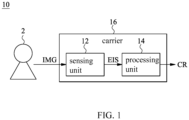
- the rapid screening device for brain disease 10 comprises a sensing unit 12, a processing unit 14 and a carrier 16. Besides, please refer to FIG. 2 as well.
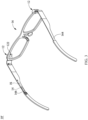
- FIG. 2 is a structural diagram which illustrates the rapid screening device for brain disease 10 in FIG. 1 .
- the sensing unit 12 may capture an image IMG of the states of patient's 2 eyeball(s) 2', such as oscillation of eyes, eye-opening, eye-closing and movements of eyeballs, etc.
- the sensing unit 12 outputs the image signal EIS of the eyeball, wherein the image IMG of at least one eyeball 2' may be resolved from the image signal EIS of the eyeball.
- the sensing unit 12 may be a single or multiple image capture device(s) 122 and the image capture device(s) 122 is (are) provided at the carrier 16 in order to capture the image IMG of the patient's 2 eyeball 2'. In this embodiment, the sensing unit 12 is described by an example of two image capture devices 122.
- the image capture device(s) 122 may be CCD, CMOS, as well as CCD or CMOS capable of capturing IR light. It is worthy to note that, the IR-type CCD or CMOS may capture the image IMG of the eyeball 2' illuminated by an IR light source (not shown in the figure) or the image IMG of the eyeball 2' presented under the natural IR light.
- the processing unit 14 is connected to the sensing unit 12.
- the processing unit 14 retrieves a plurality of the images IMG from the sensing unit 12, and the processing unit 14 executes an algorithm to generate a calculated result CR by the images IMG of the image signals EIS of the eyeball, wherein the calculated result CR is related to the symptoms of cranial nerves.
- the calculated result CR may be used to diagnose or predict the possibility that the disease may happen to the patient or the patient is suffering from the disease.
- the images IMG are the images of eye oscillation.
- the processing unit 14 may retrieve different images IMG within the predetermined time interval from the sensing unit 12.
- the processing unit 14 calculates the images IMG by executing the algorithm in methods of analyzing, matching and fitting etc. so that, for example, a displacement of the eyeball 2' in the images IMG within the predetermined time interval may be resolved.
- the algorithm may determine the frequency of the eye oscillation according to the displacement and the predetermined time interval.
- the processing unit 14 is provided at the carrier 16. In another embodiment, the processing unit 14 may be dispersively provided at the carrier 16 and remote end (or called cloud).
- the carrier 16 is provided with the sensing unit 12 and the processing unit 14.
- the carrier 16 is described by an example of a pair of glasses 16', wherein the patient 2 may be diagnosed with a disease of cranial nerves by wearing the glasses.
- the carrier 16 forms a plurality of hollow spaces 162.
- the sensing unit 12 is provided at a side of the plurality of hollow spaces 162 and, by fixing the sensing unit 12, the image IMG of the patient's 2 eyeball 2' can be captured stably.
- the sensing unit 12 is capable of capturing the image IMG directly, and the patient 2 may still view the external environment out of the carrier 16 from the hollow spaces 162 which are not obstructed by the sensing unit 12.
- the sensing unit 12 may be provided, for example, at the central part of the hollow spaces 162 as well such that the sensing unit 12 may completely obstruct the vision of the patient 2 from viewing the external environment.
- the rapid screening device for brain disease 10 further comprises a communication unit (not shown in the figure), which may connect at least one of the processing unit 14 and the sensing unit 12.
- the communication unit complies with the wireless communication standard or wire communication standard.
- the communication unit may output at least one of the image(s) IMG and the calculated result CR via wireless or wire communication.
- the rapid screening device for brain disease 10' further comprises an indication unit 18 besides the sensing unit 12, the processing unit 14 and the carrier 16 in the first example.
- the indication unit 18 is connected to the processing unit 14.
- the indication unit 18 receives an indication signal IS from the processing unit 14 in order to instruct the patient 2 to change the states of his/her eyeball 2'.
- the indication unit 18 may generate at least one of sound, light, temperature, voice message, vibration, electrical stimulation, pressure (such as hydraulic pressure and pneumatic pressure etc.) and force (such as a force to draw the eyelids) in order to instruct the patient 2 to change the states of his/her eyeball 2'.
- the indication unit 18 may instruct the patient 2 to control the eyeball 2' to be certain states such as moving left, moving right, moving up, moving down, rolling eyeballs, opening eyes, closing eyes, etc. by the speaker 166 provided at the temple 164 of the glasses 16'.
- the processing unit 14 may simultaneously record at least one of the starting timing, the stopping timing and the indicating direction of the indication signal IS to allow the processing unit 14 being able to determine the relation between the image IMG and the indication signal IS.
- the image IMG indicates which state that the eyeball 2' is carrying out.
- the rapid screening device for brain disease 10 further comprises a supporting bracket 20 besides the sensing unit 12, the processing unit 14 and the carrier 16 in the first example.
- the supporting bracket 20 is provided at the hollow spaces 162.
- the supporting bracket 20 is a crossing structure and an annular structure provided in a crossing structure.
- the sensing unit 12 is provided on the supporting bracket 20, and the indication unit 18 in the second example may be provided on the supporting bracket 20 as well.
- the indication unit 18 is light emitted diodes (LEDs) 182, 184, 186, wherein LED 182 indicates “ready to test”, LED 184 indicates the direction that the eyeball 2' shall fixate and LED 186 indicates "test over”.
- the rapid screening device for brain disease 10′′′ further comprises a reflection unit 22 besides the sensing unit 12, the processing unit 14 and the carrier 16 in the first example.
- the reflection unit 22 is provided at a side of the hollow spaces 162.
- the reflection unit 22 is described by an example of a reflection optical lens with IR reflection coating.
- the reflection optical lens is capable of reflecting the light with IR spectrum and allowing the light with non-IR spectrum to transmit.
- the sensing unit 12 captures the image IMG of the patient's 2 eyeball 2' via the reflection unit 22.
- the optical intensity of the image IMG is inadequate because the eyeball 2' is obstructed by the carrier 16.
- the optical intensity of the image IMG may be enhanced by the IR light source (not shown in the figure) so that the image IMG may be directly captured by the sensing unit 12 which is capable of capturing IR spectrum, or the image IMG may be captured by adopting the reflection unit 22 and the sensing unit 12 capable of capturing IR spectrum in the present embodiment.
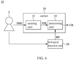
- the rapid screening device for brain disease 10" further comprises a biological detection unit 24 besides the sensing unit 12, the processing unit 14 and the carrier 16 in the first example.
- the biological detection unit 24 is connected to the processing unit 14 in order to stimulate the patient 2 to generate a biological reaction (such as opening eyes, closing eyes, twitching eyelids, quickened pulses, slowed pulses etc.) and detect the corresponding biological reaction to generate biological signal BS.
- the processing unit 14 executes the algorithm to generate the calculated result CR by the images IMG of the image signals EIS of the eyeball and the biological signal BS, wherein the calculated result CR is provided to diagnose that the disease happens to the patient 2.
- the biological detection unit 24 may carry out biologically neural-electrical stimulation, such as generating local electrical shock at somewhere of the patent's 2 head, to stimulate the patient's 2 biological reaction, and according to the biological reaction generated by the patient 2 while the part is electrically shocked, further provide the biological signals BS corresponding to the biological reaction to the processing unit 14, which allows the processing unit 14 to more accurately determine if the disease happens to the patient 2 based on the biological signal BS and the images IMG.
- biologically neural-electrical stimulation such as generating local electrical shock at somewhere of the patent's 2 head
- the biological detection unit 24 may also carry out the measurement of the blood velocity such as detecting the blood velocity in a vein inside a cranium or a cervical part or the difference of the blood velocity between the vein in the cranium and in the cervical part by a meter, which allows the processing unit 14 to more accurately determine if the disease happens to the patient 2 by the biological signal BS of blood velocity (or the difference of the blood velocity) and the images IMG.
Landscapes
- Health & Medical Sciences (AREA)
- Life Sciences & Earth Sciences (AREA)
- Engineering & Computer Science (AREA)
- General Health & Medical Sciences (AREA)
- Physics & Mathematics (AREA)
- Medical Informatics (AREA)
- Animal Behavior & Ethology (AREA)
- Public Health (AREA)
- Biophysics (AREA)
- Veterinary Medicine (AREA)
- Surgery (AREA)
- Biomedical Technology (AREA)
- Heart & Thoracic Surgery (AREA)
- Molecular Biology (AREA)
- Pathology (AREA)
- Neurology (AREA)
- Physiology (AREA)
- Neurosurgery (AREA)
- Psychology (AREA)
- Dentistry (AREA)
- Oral & Maxillofacial Surgery (AREA)
- Nuclear Medicine, Radiotherapy & Molecular Imaging (AREA)
- Radiology & Medical Imaging (AREA)
- Quality & Reliability (AREA)
- Computer Vision & Pattern Recognition (AREA)
- General Physics & Mathematics (AREA)
- Theoretical Computer Science (AREA)
- Ophthalmology & Optometry (AREA)
- Human Computer Interaction (AREA)
- Eye Examination Apparatus (AREA)
- Magnetic Resonance Imaging Apparatus (AREA)
- Measurement And Recording Of Electrical Phenomena And Electrical Characteristics Of The Living Body (AREA)
Description
- The present invention is related to the field of neural diagnosis devices, particularly a rapid screening device for brain disease, which determines symptoms of cranial nerve by detecting the states of a patient's eyeballs.
- According to clinical statistics, one in every two people may ever have headache in a year, and one in every five people may ever have vertigo in a year. In other words, about 20%~50% of the population suffer from headache and/or vertigo (which are called "symptoms" afterwards.).
- Take USA for example, while patients have the symptoms stated above, around 9.6 million patients would resort to the emergency room every year. Take Taiwan for example, while patients have the symptoms, around 0.5 million patients would also resort to the emergency room every year, i.e., averagely more than 1400 patients per day.
- Around 90% of the symptoms are benign, meaning they have no effects on the patients, but the other 10% of the symptoms is not appertaining to benignancy such as cerebral palsy, cerebral edema or cerebroma etc. Most of those not appertaining to benignancy stated above require instant treatment in order to avert endangering patients' lives.
- However, according to the experiences of emergency physicians and academic statistics, the possibility that the cause of the symptoms is wrongfully diagnosed is about 5% during the diagnosis in an emergency room, and the possibility that the cause of the symptoms diagnosed by an emergency physician is different from that by a medical specialist is even up to 50%. In the 50% possibility, if it happens to be the cause not appertaining to benignancy (of which the possibility is 10%), the instant wrongful diagnosis may result in irreversible consequences.
- Conventionally, instruments capable of making precise examination do exist, such as computed tomography (CT) and magnetic resonance imaging (MRI). However, it may be comprehended from certain data that, in the past 10 years, although the number of the patients scanned by the instruments increases, the number of the patients whose cause of the symptoms is certainly determined after scanning decreases. In other words, the results show that it is unnecessary for lots of patients to use the instruments stated above. In USA, adopting CT to scan the patient's brain may cost several hundreds of US dollars while adopting MRI may cost even thousands of US dollars. Therefore, inefficient examinations (i.e., instruments of such precise examination is actually not necessary for all patients) may results in enormous waste in medical cost.
- In view of the disadvantages resulting from the inadequacy in instant diagnosis of the symptoms in convention, such as failure of instant diagnosis for serious diseases, missing the golden timing for treatment, causing medical dispute, generating tension in doctor-patient relationship, waste of medical resources and social cost etc., the present invention therefore provides a rapid screening device for brain disease to lower the possibility of wrongful diagnosis and the waste of resources, further raising the survival rate and cure rate of patients. Some designs are known from
EP 2 853 937 A1US 2013/308099 A1 , fromUS 2014/171756 A1 , fromUS 6 820 979 B1 , fromWO 2014/179558 A1 , fromEP 1 219 243 A1 , fromWO 2006/047816 A1 , and fromWO2015/051272 A1 . In particularWO2015/051272 A1 describes an on-site eye tracker to detect mild traumatic brain injury comprising an eye cover unit with two micro-cameras and two infrared LED lights mounted inside the unit. The unit can be a pair of virtual reality goggles or a eye covering unit which shields substantially all external light from a user's eyes. - A first objective of the present invention is to provide a rapid screening device for brain disease, which is capable of assisting doctors to manipulate neural examination such as headache or vertigo in order to lower the possibility of wrongful diagnosis. The neural examination may be, for example, optic nerve examination (such as examining if there is defect in visual field and if the opening rate of pupils are different, etc.), eyeball examination (such as examining oculomotor, trochlea, strabismus, oscillation of eyeballs (or nystagmus) etc.), trigeminus examination (such as examining the perception of both sides of face), vestibular nerve examination (such as oscillation of eyeballs (or nystagmus) and hearing examination) and facial nerve examination (such as examining the slant of face).
- A second objective of the present invention is to provide the rapid screening device for brain disease, which may effectively assist a doctor to diagnose the cause of the headache or vertigo after inquiring a patient' s medical history.
- A third objective of the present invention is to provide the rapid screening device for brain disease, which can be utilized, for example, at triage in an emergency room or after inquiry by a doctor, in order to enhance the accuracy of diagnosis.
- A fourth objective of the present invention is to provide the rapid screening device for brain disease, which can be easily operated by a patient first in order to self-conclude if a disease of cranial nerves may possibly happen, is happening or had happened.
- A fifth objective of the present invention is to provide the rapid screening device for brain disease so that the diagnosis may be proceeded under the conditions that the patient is conscious, with eye-opening, suffering eye disease, with drooping eyelids, with half-closed eyes or with fully-closed eyes.
- A sixth objective of the present invention is to provide the rapid screening device for brain disease, which owns advantages of small volume, simple equipment, easy to maintain, convenient to operate in consultation room, low cost, rapid screening, functional check, easy to carry/use and flexible diversity etc.
- According to the present invention, a rapid screening device as defined by claim 1 is provided. The dependent claims show some examples thereof.
-
-
FIG. 1 is a block diagram of a rapid screening device for brain disease in a first example, whereinFig. 1 does not show all features of claim 1. -
FIG. 2 is a structural diagram to illustrate a rapid screening device for brain disease which is not according to the invention. -
FIG. 3 is a structural diagram of a rapid screening device for brain disease which is not according to the invention. -
FIG. 4 is a structural diagram of a rapid screening device for brain disease in an embodiment of the present invention. -
FIG. 5 is a structural diagram of a rapid screening device for brain disease which is not according to the invention. -
FIG. 6 is a block diagram of a rapid screening device for brain disease in a further example, whereinFig. 6 does not show all features of claim 1. - Refer to
FIG. 1 , which is a block diagram of a rapid screening device for brain disease in an example. InFIG. 1 , the rapid screening device forbrain disease 10 may be used to diagnose a patient's disease of cranial nerves by the states of the patient's 2 eyeball(s) 2', wherein the states of the eyeball(s) 2' may be oscillation (nystagmus), displacement, eye-opening, eye-closing, structure of eyeball(s) and fundus etc., and the disease of cranial nerves may be apoplexia, cerebral hemorrhage , headache, vertigo and cerebral infarct, etc. Besides, the form factor of the rapid screening device forbrain disease 10 may be glasses-clipped-on type, table-machine type, head-mounted type, hand-held type and necklace-hitched type etc.In this embodiment, the rapid screening device forbrain disease 10 is described by an example of glasses-clipped-on type. - The rapid screening device for
brain disease 10 comprises asensing unit 12, aprocessing unit 14 and acarrier 16. Besides, please refer toFIG. 2 as well.FIG. 2 is a structural diagram which illustrates the rapid screening device forbrain disease 10 inFIG. 1 . - The
sensing unit 12 may capture an image IMG of the states of patient's 2 eyeball(s) 2', such as oscillation of eyes, eye-opening, eye-closing and movements of eyeballs, etc. Thesensing unit 12 outputs the image signal EIS of the eyeball, wherein the image IMG of at least one eyeball 2' may be resolved from the image signal EIS of the eyeball. Thesensing unit 12 may be a single or multiple image capture device(s) 122 and the image capture device(s) 122 is (are) provided at thecarrier 16 in order to capture the image IMG of the patient's 2 eyeball 2'. In this embodiment, thesensing unit 12 is described by an example of twoimage capture devices 122. The image capture device(s) 122 may be CCD, CMOS, as well as CCD or CMOS capable of capturing IR light. It is worthy to note that, the IR-type CCD or CMOS may capture the image IMG of the eyeball 2' illuminated by an IR light source (not shown in the figure) or the image IMG of the eyeball 2' presented under the natural IR light. - The
processing unit 14 is connected to thesensing unit 12. Theprocessing unit 14 retrieves a plurality of the images IMG from thesensing unit 12, and theprocessing unit 14 executes an algorithm to generate a calculated result CR by the images IMG of the image signals EIS of the eyeball, wherein the calculated result CR is related to the symptoms of cranial nerves. In other words, the calculated result CR may be used to diagnose or predict the possibility that the disease may happen to the patient or the patient is suffering from the disease. - For example, the images IMG are the images of eye oscillation. The
processing unit 14 may retrieve different images IMG within the predetermined time interval from thesensing unit 12. Theprocessing unit 14 calculates the images IMG by executing the algorithm in methods of analyzing, matching and fitting etc. so that, for example, a displacement of the eyeball 2' in the images IMG within the predetermined time interval may be resolved. The algorithm may determine the frequency of the eye oscillation according to the displacement and the predetermined time interval. - In the present embodiment, the
processing unit 14 is provided at thecarrier 16. In another embodiment, theprocessing unit 14 may be dispersively provided at thecarrier 16 and remote end (or called cloud). - The
carrier 16 is provided with thesensing unit 12 and theprocessing unit 14. In the present embodiment, thecarrier 16 is described by an example of a pair of glasses 16', wherein thepatient 2 may be diagnosed with a disease of cranial nerves by wearing the glasses. Thecarrier 16 forms a plurality ofhollow spaces 162. Thesensing unit 12 is provided at a side of the plurality ofhollow spaces 162 and, by fixing thesensing unit 12, the image IMG of the patient's 2 eyeball 2' can be captured stably. In the present embodiment, thesensing unit 12 is capable of capturing the image IMG directly, and thepatient 2 may still view the external environment out of thecarrier 16 from thehollow spaces 162 which are not obstructed by thesensing unit 12. In another embodiment, thesensing unit 12 may be provided, for example, at the central part of thehollow spaces 162 as well such that thesensing unit 12 may completely obstruct the vision of thepatient 2 from viewing the external environment. - In another embodiment, the rapid screening device for
brain disease 10 further comprises a communication unit (not shown in the figure), which may connect at least one of theprocessing unit 14 and thesensing unit 12. The communication unit complies with the wireless communication standard or wire communication standard. In other words, the communication unit may output at least one of the image(s) IMG and the calculated result CR via wireless or wire communication. - Refer to
FIG. 3 , which is a structural diagram of the rapid screening device for brain disease in a second example. InFIG. 3 , the rapid screening device for brain disease 10' further comprises an indication unit 18 besides thesensing unit 12, theprocessing unit 14 and thecarrier 16 in the first example. - The indication unit 18 is connected to the
processing unit 14. The indication unit 18 receives an indication signal IS from theprocessing unit 14 in order to instruct thepatient 2 to change the states of his/her eyeball 2'. The indication unit 18 may generate at least one of sound, light, temperature, voice message, vibration, electrical stimulation, pressure (such as hydraulic pressure and pneumatic pressure etc.) and force (such as a force to draw the eyelids) in order to instruct thepatient 2 to change the states of his/her eyeball 2'. In this embodiment, the indication unit 18 may instruct thepatient 2 to control the eyeball 2' to be certain states such as moving left, moving right, moving up, moving down, rolling eyeballs, opening eyes, closing eyes, etc. by thespeaker 166 provided at thetemple 164 of the glasses 16'. - Meanwhile, the
processing unit 14 may simultaneously record at least one of the starting timing, the stopping timing and the indicating direction of the indication signal IS to allow theprocessing unit 14 being able to determine the relation between the image IMG and the indication signal IS. For example, the image IMG indicates which state that the eyeball 2' is carrying out. - Refer to
FIG. 4 , which is a structural diagram of the rapid screening device for brain disease in an embodiment of the present invention. InFIG. 4 , the rapid screening device forbrain disease 10" further comprises a supportingbracket 20 besides thesensing unit 12, theprocessing unit 14 and thecarrier 16 in the first example. - The supporting
bracket 20 is provided at thehollow spaces 162. The supportingbracket 20 is a crossing structure and an annular structure provided in a crossing structure. Thesensing unit 12 is provided on the supportingbracket 20, and the indication unit 18 in the second example may be provided on the supportingbracket 20 as well. The indication unit 18 is light emitted diodes (LEDs) 182, 184, 186, whereinLED 182 indicates "ready to test",LED 184 indicates the direction that the eyeball 2' shall fixate andLED 186 indicates "test over". - Refer to
FIG. 5 , which is a structural diagram of the rapid screening device for brain disease in a third example. InFIG. 5 , the rapid screening device forbrain disease 10‴ further comprises areflection unit 22 besides thesensing unit 12, theprocessing unit 14 and thecarrier 16 in the first example. - The
reflection unit 22 is provided at a side of thehollow spaces 162. In the present embodiment, thereflection unit 22 is described by an example of a reflection optical lens with IR reflection coating. The reflection optical lens is capable of reflecting the light with IR spectrum and allowing the light with non-IR spectrum to transmit. Thesensing unit 12 captures the image IMG of the patient's 2 eyeball 2' via thereflection unit 22. - Generally, when proceeding diagnosis, the optical intensity of the image IMG is inadequate because the eyeball 2' is obstructed by the
carrier 16. The optical intensity of the image IMG may be enhanced by the IR light source (not shown in the figure) so that the image IMG may be directly captured by thesensing unit 12 which is capable of capturing IR spectrum, or the image IMG may be captured by adopting thereflection unit 22 and thesensing unit 12 capable of capturing IR spectrum in the present embodiment. - Refer to
FIG. 6 , which is a structural diagram of the rapid screening device for brain disease in a fourth example. InFIG. 6 , the rapid screening device forbrain disease 10"" further comprises abiological detection unit 24 besides thesensing unit 12, theprocessing unit 14 and thecarrier 16 in the first example. - The
biological detection unit 24 is connected to theprocessing unit 14 in order to stimulate thepatient 2 to generate a biological reaction (such as opening eyes, closing eyes, twitching eyelids, quickened pulses, slowed pulses etc.) and detect the corresponding biological reaction to generate biological signal BS. Theprocessing unit 14 executes the algorithm to generate the calculated result CR by the images IMG of the image signals EIS of the eyeball and the biological signal BS, wherein the calculated result CR is provided to diagnose that the disease happens to thepatient 2. - For example, the
biological detection unit 24 may carry out biologically neural-electrical stimulation, such as generating local electrical shock at somewhere of the patent's 2 head, to stimulate the patient's 2 biological reaction, and according to the biological reaction generated by thepatient 2 while the part is electrically shocked, further provide the biological signals BS corresponding to the biological reaction to theprocessing unit 14, which allows theprocessing unit 14 to more accurately determine if the disease happens to thepatient 2 based on the biological signal BS and the images IMG. - In another embodiment, the
biological detection unit 24 may also carry out the measurement of the blood velocity such as detecting the blood velocity in a vein inside a cranium or a cervical part or the difference of the blood velocity between the vein in the cranium and in the cervical part by a meter, which allows theprocessing unit 14 to more accurately determine if the disease happens to thepatient 2 by the biological signal BS of blood velocity (or the difference of the blood velocity) and the images IMG.
Claims (4)
- A rapid screening device for a brain disease to determine a patient's disease of cranial nerves by states of the patient's eyeballs comprising:a sensing unit (12) consisting of two image capture devices (122) configured to capture images of the eyeballs and output image signals of the eyeballs wherein the images of the eyeballs are resolved from the image signals of the eyeballs;a processing unit (14) connected to the sensing unit (12), wherein the processing unit (14) is configured to retrieve a plurality of the images from the sensing unit within a predetermined time interval and execute an algorithm to generate a calculated result related to the symptoms of cranial nerves from the image signals of the eyeballs, wherein the calculated result is provided to diagnose or predict that the disease happens to the patient;an indication unit (18) consisting of light emitting diodes (182, 184, 186) configured to receive an indication signal from the processing unit and instruct the patient to control the eyeballs; anda carrier (16) provided with the sensing unit (12), the indication unit (18) and the processing unit (14),wherein the carrier (16) is in a form of a pair of glasses,wherein the pair of glasses defines two hollow spaces (162),wherein two supporting brackets (20) are provided at the two hollow spaces (162), respectively,wherein the two image capturing devices (122) are provided at the two supporting brackets (20), respectively,wherein each of the supporting brackets (20) includes a respective crossing structure and a respective annular structure, and wherein the respective annular structure is connected with the respective crossing structure in a respective intersectional manner and surrounds a respective intersecting portion of the respective crossing structure,wherein the light emitting diodes (182, 184, 186) are provided on the annular structure of the supporting brackets,wherein on each of the two supporting brackets (20), on its respective crossing structure, a respective one of the respective two image capturing devices (122) is provided in the center of the annular structure.
- The rapid screening device for brain disease of claim 1, wherein the calculated result is configured to record at least one of a starting time, a stopping time and a direction of indication, which are generated by the indication signal.
- The rapid screening device for brain disease of claim 1, further comprising a communication unit connected to at least one of the processing unit (14) and the sensing unit (12), wherein the communication unit is configured to output at least one of the image and the calculated result.
- The rapid screening device for brain disease of claim 1, further comprising a biological detection unit connected to the processing unit (14) in order to stimulate the patient to generate a biological reaction and detect a corresponding biological reaction to generate a biological signal, wherein the processing unit (14) is configured to execute the algorithm to generate the calculated result related to the symptoms of cranial nerves from the image signals of the eyeballs and the biological signal, and wherein the calculated result is provided to diagnose that the disease happens to the patient.
Applications Claiming Priority (2)
| Application Number | Priority Date | Filing Date | Title |
|---|---|---|---|
| US201562171115P | 2015-06-04 | 2015-06-04 | |
| PCT/CN2016/088293 WO2016192688A1 (en) | 2015-06-04 | 2016-07-04 | Apparatus for rapidly screening for brain disease |
Publications (3)
| Publication Number | Publication Date |
|---|---|
| EP3305177A1 EP3305177A1 (en) | 2018-04-11 |
| EP3305177A4 EP3305177A4 (en) | 2019-02-27 |
| EP3305177B1 true EP3305177B1 (en) | 2023-08-23 |
Family
ID=57440087
Family Applications (1)
| Application Number | Title | Priority Date | Filing Date |
|---|---|---|---|
| EP16802611.0A Active EP3305177B1 (en) | 2015-06-04 | 2016-07-04 | Apparatus for rapidly screening for brain disease |
Country Status (5)
| Country | Link |
|---|---|
| US (1) | US10026169B2 (en) |
| EP (1) | EP3305177B1 (en) |
| CN (1) | CN107847129A (en) |
| TW (1) | TWI616188B (en) |
| WO (1) | WO2016192688A1 (en) |
Families Citing this family (2)
| Publication number | Priority date | Publication date | Assignee | Title |
|---|---|---|---|---|
| WO2022159628A1 (en) * | 2021-01-22 | 2022-07-28 | Zinn Labs, Inc. | Headset integrated into healthcare platform |
| EP4316350B1 (en) * | 2022-08-05 | 2026-01-07 | Siemens Healthineers AG | Image based detection of characteristic eye movements |
Family Cites Families (17)
| Publication number | Priority date | Publication date | Assignee | Title |
|---|---|---|---|---|
| US4456347A (en) * | 1981-08-17 | 1984-06-26 | Limbic Training Systems, Inc. | Method and apparatus for facilitating relaxation |
| US4818091A (en) * | 1985-12-31 | 1989-04-04 | University Of Southern California | System and method of detecting visual field defects |
| US4826308A (en) * | 1985-12-31 | 1989-05-02 | University Of Southern California | Method and system for detecting, characterizing and monitoring optic nerve diseases |
| US6820979B1 (en) * | 1999-04-23 | 2004-11-23 | Neuroptics, Inc. | Pupilometer with pupil irregularity detection, pupil tracking, and pupil response detection capability, glaucoma screening capability, intracranial pressure detection capability, and ocular aberration measurement capability |
| EP1127534A3 (en) * | 2000-02-24 | 2002-05-29 | Matsushita Electric Works, Ltd. | Non-invasive brain function examination |
| EP1219243A1 (en) * | 2000-12-28 | 2002-07-03 | Matsushita Electric Works, Ltd. | Non-invasive brain function examination |
| US7731360B2 (en) * | 2003-11-07 | 2010-06-08 | Neuro Kinetics | Portable video oculography system |
| EP1811890A4 (en) * | 2004-11-01 | 2009-09-09 | Eye Diagnostics Pty Ltd | Device and method for investigating changes in the eye |
| CN101427915A (en) * | 2008-11-14 | 2009-05-13 | 昆明依利科特科技有限公司 | Human brain status information capture and detection apparatus |
| US8911087B2 (en) * | 2011-05-20 | 2014-12-16 | Eyefluence, Inc. | Systems and methods for measuring reactions of head, eyes, eyelids and pupils |
| US9101312B2 (en) * | 2012-04-18 | 2015-08-11 | TBI Diagnostics LLC | System for the physiological evaluation of brain function |
| US9004687B2 (en) * | 2012-05-18 | 2015-04-14 | Sync-Think, Inc. | Eye tracking headset and system for neuropsychological testing including the detection of brain damage |
| BR112015027598A2 (en) * | 2013-05-01 | 2017-09-19 | Musc Found For Res Dev | DEVICE FOR MEDIATING THE BLINK REFLEX IN A HUMAN INDIVIDUAL |
| EP2853937B1 (en) * | 2013-09-26 | 2017-11-01 | Manfred Stickel | Goggle-like mobile apparatus and method for recording images of a pupil of a person |
| AU2014329339B2 (en) * | 2013-10-04 | 2018-10-25 | Indiana University Research And Technology Corporation | Eye movement monitoring of brain function |
| US9905008B2 (en) * | 2013-10-10 | 2018-02-27 | University Of Rochester | Automated fundus image field detection and quality assessment |
| KR20150110254A (en) * | 2014-03-21 | 2015-10-02 | 삼성전자주식회사 | Head mounted display device and operating method thereof |
-
2016
- 2016-06-04 TW TW105117701A patent/TWI616188B/en active
- 2016-06-06 US US15/174,534 patent/US10026169B2/en active Active - Reinstated
- 2016-07-04 EP EP16802611.0A patent/EP3305177B1/en active Active
- 2016-07-04 CN CN201680032303.9A patent/CN107847129A/en active Pending
- 2016-07-04 WO PCT/CN2016/088293 patent/WO2016192688A1/en not_active Ceased
Non-Patent Citations (1)
| Title |
|---|
| BRANDT T ET AL: "General vestibular testing", CLINICAL NEUROPHYSIOLOGY, ELSEVIER, AMSTERDAM, NL, vol. 116, no. 2, 1 February 2005 (2005-02-01), pages 406 - 426, XP027706359, ISSN: 1388-2457, [retrieved on 20050201] * |
Also Published As
| Publication number | Publication date |
|---|---|
| CN107847129A (en) | 2018-03-27 |
| EP3305177A1 (en) | 2018-04-11 |
| WO2016192688A1 (en) | 2016-12-08 |
| TW201705908A (en) | 2017-02-16 |
| US20170039703A1 (en) | 2017-02-09 |
| EP3305177A4 (en) | 2019-02-27 |
| TWI616188B (en) | 2018-03-01 |
| US10026169B2 (en) | 2018-07-17 |
Similar Documents
| Publication | Publication Date | Title |
|---|---|---|
| KR102142841B1 (en) | AI-based ECG reading system | |
| US11684255B2 (en) | Device and method for determination of pupil size in a subject having closed eyelids | |
| US8585609B2 (en) | Quantitative, non-invasive, clinical diagnosis of traumatic brain injury using simulated distance visual stimulus device for neurologic testing | |
| JP7836833B2 (en) | A visual system for diagnosing and monitoring mental health | |
| JP6129161B2 (en) | System and method for measuring head, eye, eyelid and pupil response | |
| US20150223683A1 (en) | System For Synchronously Sampled Binocular Video-Oculography Using A Single Head-Mounted Camera | |
| US20180249941A1 (en) | Oculometric Neurological Examination (ONE) Appliance | |
| KR20190005219A (en) | Augmented Reality Systems and Methods for User Health Analysis | |
| WO2020175759A1 (en) | System and method for analyzing stress of user and managing individual mental health, using hmd device having biosignal sensors mounted therein | |
| KR20200003094A (en) | Head mountable device | |
| WO2014015378A1 (en) | A mobile computing device, application server, computer readable storage medium and system for calculating a vitality indicia, detecting an environmental hazard, vision assistance and detecting disease | |
| US10835120B2 (en) | Extended medical test system | |
| KR101637314B1 (en) | Apparatus to image and analyses the eyes and fundus oculi and its method thereof | |
| Lakshminarayanan et al. | " Smartphone Science" in Eye Care and Medicine | |
| US10026169B2 (en) | Rapid screening device for brain disease | |
| TWI823015B (en) | Decision support system and method thereof for neurological disorders | |
| US11510583B2 (en) | Diagnostic mask and method | |
| US20250025040A1 (en) | Methods, systems, and computer readable media for biometric ocular photometry | |
| US12557984B2 (en) | Method and apparatus for measuring relative afferent pupillary defects | |
| Mantokoudis et al. | Video-oculography in the emergency department: an “ECG” for the eyes in the acute vestibular syndrome | |
| KR20220168883A (en) | Method for Screening Strabismus and Device therefor | |
| CN204351799U (en) | Portable eye checkout facility and system | |
| US20220233134A1 (en) | System and Method for Stroke Detection and Prevention | |
| EP4678091A1 (en) | System and method for monitoring health status | |
| US20250169694A1 (en) | Retinal imaging for detection of biomarkers associated with neurodegenerative diseases |
Legal Events
| Date | Code | Title | Description |
|---|---|---|---|
| STAA | Information on the status of an ep patent application or granted ep patent |
Free format text: STATUS: THE INTERNATIONAL PUBLICATION HAS BEEN MADE |
|
| PUAI | Public reference made under article 153(3) epc to a published international application that has entered the european phase |
Free format text: ORIGINAL CODE: 0009012 |
|
| STAA | Information on the status of an ep patent application or granted ep patent |
Free format text: STATUS: REQUEST FOR EXAMINATION WAS MADE |
|
| 17P | Request for examination filed |
Effective date: 20171201 |
|
| AK | Designated contracting states |
Kind code of ref document: A1 Designated state(s): AL AT BE BG CH CY CZ DE DK EE ES FI FR GB GR HR HU IE IS IT LI LT LU LV MC MK MT NL NO PL PT RO RS SE SI SK SM TR |
|
| AX | Request for extension of the european patent |
Extension state: BA ME |
|
| DAV | Request for validation of the european patent (deleted) | ||
| DAX | Request for extension of the european patent (deleted) | ||
| A4 | Supplementary search report drawn up and despatched |
Effective date: 20190124 |
|
| RIC1 | Information provided on ipc code assigned before grant |
Ipc: A61B 5/11 20060101ALI20190118BHEP Ipc: A61B 3/113 20060101AFI20190118BHEP Ipc: A61B 5/00 20060101ALI20190118BHEP |
|
| STAA | Information on the status of an ep patent application or granted ep patent |
Free format text: STATUS: EXAMINATION IS IN PROGRESS |
|
| 17Q | First examination report despatched |
Effective date: 20201202 |
|
| GRAP | Despatch of communication of intention to grant a patent |
Free format text: ORIGINAL CODE: EPIDOSNIGR1 |
|
| STAA | Information on the status of an ep patent application or granted ep patent |
Free format text: STATUS: GRANT OF PATENT IS INTENDED |
|
| INTG | Intention to grant announced |
Effective date: 20230309 |
|
| GRAS | Grant fee paid |
Free format text: ORIGINAL CODE: EPIDOSNIGR3 |
|
| GRAA | (expected) grant |
Free format text: ORIGINAL CODE: 0009210 |
|
| STAA | Information on the status of an ep patent application or granted ep patent |
Free format text: STATUS: THE PATENT HAS BEEN GRANTED |
|
| RAP1 | Party data changed (applicant data changed or rights of an application transferred) |
Owner name: NEUROBIT TECHNOLOGIES CO., LTD. |
|
| AK | Designated contracting states |
Kind code of ref document: B1 Designated state(s): AL AT BE BG CH CY CZ DE DK EE ES FI FR GB GR HR HU IE IS IT LI LT LU LV MC MK MT NL NO PL PT RO RS SE SI SK SM TR |
|
| REG | Reference to a national code |
Ref country code: GB Ref legal event code: FG4D |
|
| REG | Reference to a national code |
Ref country code: CH Ref legal event code: EP |
|
| REG | Reference to a national code |
Ref country code: IE Ref legal event code: FG4D |
|
| REG | Reference to a national code |
Ref country code: DE Ref legal event code: R096 Ref document number: 602016082158 Country of ref document: DE |
|
| REG | Reference to a national code |
Ref country code: LT Ref legal event code: MG9D |
|
| REG | Reference to a national code |
Ref country code: NL Ref legal event code: MP Effective date: 20230823 |
|
| REG | Reference to a national code |
Ref country code: AT Ref legal event code: MK05 Ref document number: 1601592 Country of ref document: AT Kind code of ref document: T Effective date: 20230823 |
|
| PG25 | Lapsed in a contracting state [announced via postgrant information from national office to epo] |
Ref country code: GR Free format text: LAPSE BECAUSE OF FAILURE TO SUBMIT A TRANSLATION OF THE DESCRIPTION OR TO PAY THE FEE WITHIN THE PRESCRIBED TIME-LIMIT Effective date: 20231124 |
|
| PG25 | Lapsed in a contracting state [announced via postgrant information from national office to epo] |
Ref country code: IS Free format text: LAPSE BECAUSE OF FAILURE TO SUBMIT A TRANSLATION OF THE DESCRIPTION OR TO PAY THE FEE WITHIN THE PRESCRIBED TIME-LIMIT Effective date: 20231223 |
|
| PG25 | Lapsed in a contracting state [announced via postgrant information from national office to epo] |
Ref country code: SE Free format text: LAPSE BECAUSE OF FAILURE TO SUBMIT A TRANSLATION OF THE DESCRIPTION OR TO PAY THE FEE WITHIN THE PRESCRIBED TIME-LIMIT Effective date: 20230823 Ref country code: RS Free format text: LAPSE BECAUSE OF FAILURE TO SUBMIT A TRANSLATION OF THE DESCRIPTION OR TO PAY THE FEE WITHIN THE PRESCRIBED TIME-LIMIT Effective date: 20230823 Ref country code: PT Free format text: LAPSE BECAUSE OF FAILURE TO SUBMIT A TRANSLATION OF THE DESCRIPTION OR TO PAY THE FEE WITHIN THE PRESCRIBED TIME-LIMIT Effective date: 20231226 Ref country code: NO Free format text: LAPSE BECAUSE OF FAILURE TO SUBMIT A TRANSLATION OF THE DESCRIPTION OR TO PAY THE FEE WITHIN THE PRESCRIBED TIME-LIMIT Effective date: 20231123 Ref country code: NL Free format text: LAPSE BECAUSE OF FAILURE TO SUBMIT A TRANSLATION OF THE DESCRIPTION OR TO PAY THE FEE WITHIN THE PRESCRIBED TIME-LIMIT Effective date: 20230823 Ref country code: LV Free format text: LAPSE BECAUSE OF FAILURE TO SUBMIT A TRANSLATION OF THE DESCRIPTION OR TO PAY THE FEE WITHIN THE PRESCRIBED TIME-LIMIT Effective date: 20230823 Ref country code: LT Free format text: LAPSE BECAUSE OF FAILURE TO SUBMIT A TRANSLATION OF THE DESCRIPTION OR TO PAY THE FEE WITHIN THE PRESCRIBED TIME-LIMIT Effective date: 20230823 Ref country code: IS Free format text: LAPSE BECAUSE OF FAILURE TO SUBMIT A TRANSLATION OF THE DESCRIPTION OR TO PAY THE FEE WITHIN THE PRESCRIBED TIME-LIMIT Effective date: 20231223 Ref country code: HR Free format text: LAPSE BECAUSE OF FAILURE TO SUBMIT A TRANSLATION OF THE DESCRIPTION OR TO PAY THE FEE WITHIN THE PRESCRIBED TIME-LIMIT Effective date: 20230823 Ref country code: GR Free format text: LAPSE BECAUSE OF FAILURE TO SUBMIT A TRANSLATION OF THE DESCRIPTION OR TO PAY THE FEE WITHIN THE PRESCRIBED TIME-LIMIT Effective date: 20231124 Ref country code: FI Free format text: LAPSE BECAUSE OF FAILURE TO SUBMIT A TRANSLATION OF THE DESCRIPTION OR TO PAY THE FEE WITHIN THE PRESCRIBED TIME-LIMIT Effective date: 20230823 Ref country code: AT Free format text: LAPSE BECAUSE OF FAILURE TO SUBMIT A TRANSLATION OF THE DESCRIPTION OR TO PAY THE FEE WITHIN THE PRESCRIBED TIME-LIMIT Effective date: 20230823 |
|
| PG25 | Lapsed in a contracting state [announced via postgrant information from national office to epo] |
Ref country code: PL Free format text: LAPSE BECAUSE OF FAILURE TO SUBMIT A TRANSLATION OF THE DESCRIPTION OR TO PAY THE FEE WITHIN THE PRESCRIBED TIME-LIMIT Effective date: 20230823 |
|
| PG25 | Lapsed in a contracting state [announced via postgrant information from national office to epo] |
Ref country code: ES Free format text: LAPSE BECAUSE OF FAILURE TO SUBMIT A TRANSLATION OF THE DESCRIPTION OR TO PAY THE FEE WITHIN THE PRESCRIBED TIME-LIMIT Effective date: 20230823 |
|
| PG25 | Lapsed in a contracting state [announced via postgrant information from national office to epo] |
Ref country code: SM Free format text: LAPSE BECAUSE OF FAILURE TO SUBMIT A TRANSLATION OF THE DESCRIPTION OR TO PAY THE FEE WITHIN THE PRESCRIBED TIME-LIMIT Effective date: 20230823 Ref country code: RO Free format text: LAPSE BECAUSE OF FAILURE TO SUBMIT A TRANSLATION OF THE DESCRIPTION OR TO PAY THE FEE WITHIN THE PRESCRIBED TIME-LIMIT Effective date: 20230823 Ref country code: ES Free format text: LAPSE BECAUSE OF FAILURE TO SUBMIT A TRANSLATION OF THE DESCRIPTION OR TO PAY THE FEE WITHIN THE PRESCRIBED TIME-LIMIT Effective date: 20230823 Ref country code: EE Free format text: LAPSE BECAUSE OF FAILURE TO SUBMIT A TRANSLATION OF THE DESCRIPTION OR TO PAY THE FEE WITHIN THE PRESCRIBED TIME-LIMIT Effective date: 20230823 Ref country code: DK Free format text: LAPSE BECAUSE OF FAILURE TO SUBMIT A TRANSLATION OF THE DESCRIPTION OR TO PAY THE FEE WITHIN THE PRESCRIBED TIME-LIMIT Effective date: 20230823 Ref country code: CZ Free format text: LAPSE BECAUSE OF FAILURE TO SUBMIT A TRANSLATION OF THE DESCRIPTION OR TO PAY THE FEE WITHIN THE PRESCRIBED TIME-LIMIT Effective date: 20230823 Ref country code: SK Free format text: LAPSE BECAUSE OF FAILURE TO SUBMIT A TRANSLATION OF THE DESCRIPTION OR TO PAY THE FEE WITHIN THE PRESCRIBED TIME-LIMIT Effective date: 20230823 |
|
| REG | Reference to a national code |
Ref country code: DE Ref legal event code: R097 Ref document number: 602016082158 Country of ref document: DE |
|
| PG25 | Lapsed in a contracting state [announced via postgrant information from national office to epo] |
Ref country code: IT Free format text: LAPSE BECAUSE OF FAILURE TO SUBMIT A TRANSLATION OF THE DESCRIPTION OR TO PAY THE FEE WITHIN THE PRESCRIBED TIME-LIMIT Effective date: 20230823 |
|
| PLBE | No opposition filed within time limit |
Free format text: ORIGINAL CODE: 0009261 |
|
| STAA | Information on the status of an ep patent application or granted ep patent |
Free format text: STATUS: NO OPPOSITION FILED WITHIN TIME LIMIT |
|
| 26N | No opposition filed |
Effective date: 20240524 |
|
| PG25 | Lapsed in a contracting state [announced via postgrant information from national office to epo] |
Ref country code: SI Free format text: LAPSE BECAUSE OF FAILURE TO SUBMIT A TRANSLATION OF THE DESCRIPTION OR TO PAY THE FEE WITHIN THE PRESCRIBED TIME-LIMIT Effective date: 20230823 |
|
| PGFP | Annual fee paid to national office [announced via postgrant information from national office to epo] |
Ref country code: GB Payment date: 20240723 Year of fee payment: 9 |
|
| PGFP | Annual fee paid to national office [announced via postgrant information from national office to epo] |
Ref country code: FR Payment date: 20240724 Year of fee payment: 9 |
|
| PG25 | Lapsed in a contracting state [announced via postgrant information from national office to epo] |
Ref country code: BG Free format text: LAPSE BECAUSE OF FAILURE TO SUBMIT A TRANSLATION OF THE DESCRIPTION OR TO PAY THE FEE WITHIN THE PRESCRIBED TIME-LIMIT Effective date: 20230823 |
|
| PG25 | Lapsed in a contracting state [announced via postgrant information from national office to epo] |
Ref country code: BG Free format text: LAPSE BECAUSE OF FAILURE TO SUBMIT A TRANSLATION OF THE DESCRIPTION OR TO PAY THE FEE WITHIN THE PRESCRIBED TIME-LIMIT Effective date: 20230823 |
|
| PG25 | Lapsed in a contracting state [announced via postgrant information from national office to epo] |
Ref country code: MC Free format text: LAPSE BECAUSE OF FAILURE TO SUBMIT A TRANSLATION OF THE DESCRIPTION OR TO PAY THE FEE WITHIN THE PRESCRIBED TIME-LIMIT Effective date: 20230823 |
|
| REG | Reference to a national code |
Ref country code: CH Ref legal event code: PL |
|
| PG25 | Lapsed in a contracting state [announced via postgrant information from national office to epo] |
Ref country code: LU Free format text: LAPSE BECAUSE OF NON-PAYMENT OF DUE FEES Effective date: 20240704 |
|
| PG25 | Lapsed in a contracting state [announced via postgrant information from national office to epo] |
Ref country code: LU Free format text: LAPSE BECAUSE OF NON-PAYMENT OF DUE FEES Effective date: 20240704 |
|
| PG25 | Lapsed in a contracting state [announced via postgrant information from national office to epo] |
Ref country code: CH Free format text: LAPSE BECAUSE OF NON-PAYMENT OF DUE FEES Effective date: 20240731 Ref country code: BE Free format text: LAPSE BECAUSE OF NON-PAYMENT OF DUE FEES Effective date: 20240731 |
|
| REG | Reference to a national code |
Ref country code: BE Ref legal event code: MM Effective date: 20240731 |
|
| PG25 | Lapsed in a contracting state [announced via postgrant information from national office to epo] |
Ref country code: IE Free format text: LAPSE BECAUSE OF NON-PAYMENT OF DUE FEES Effective date: 20240704 |
|
| PGFP | Annual fee paid to national office [announced via postgrant information from national office to epo] |
Ref country code: DE Payment date: 20250702 Year of fee payment: 10 |
|
| PG25 | Lapsed in a contracting state [announced via postgrant information from national office to epo] |
Ref country code: CY Free format text: LAPSE BECAUSE OF FAILURE TO SUBMIT A TRANSLATION OF THE DESCRIPTION OR TO PAY THE FEE WITHIN THE PRESCRIBED TIME-LIMIT; INVALID AB INITIO Effective date: 20160704 |
|
| PG25 | Lapsed in a contracting state [announced via postgrant information from national office to epo] |
Ref country code: HU Free format text: LAPSE BECAUSE OF FAILURE TO SUBMIT A TRANSLATION OF THE DESCRIPTION OR TO PAY THE FEE WITHIN THE PRESCRIBED TIME-LIMIT; INVALID AB INITIO Effective date: 20160704 |
|
| GBPC | Gb: european patent ceased through non-payment of renewal fee |
Effective date: 20250704 |
|
| PG25 | Lapsed in a contracting state [announced via postgrant information from national office to epo] |
Ref country code: GB Free format text: LAPSE BECAUSE OF NON-PAYMENT OF DUE FEES Effective date: 20250704 |
|
| PG25 | Lapsed in a contracting state [announced via postgrant information from national office to epo] |
Ref country code: FR Free format text: LAPSE BECAUSE OF NON-PAYMENT OF DUE FEES Effective date: 20250731 |