EP3305050A1 - Link holder - Google Patents
Link holder Download PDFInfo
- Publication number
- EP3305050A1 EP3305050A1 EP17189175.7A EP17189175A EP3305050A1 EP 3305050 A1 EP3305050 A1 EP 3305050A1 EP 17189175 A EP17189175 A EP 17189175A EP 3305050 A1 EP3305050 A1 EP 3305050A1
- Authority
- EP
- European Patent Office
- Prior art keywords
- ball element
- link holder
- hook
- link
- holder
- Prior art date
- Legal status (The legal status is an assumption and is not a legal conclusion. Google has not performed a legal analysis and makes no representation as to the accuracy of the status listed.)
- Granted
Links
Images


Classifications
-
- A—HUMAN NECESSITIES
- A01—AGRICULTURE; FORESTRY; ANIMAL HUSBANDRY; HUNTING; TRAPPING; FISHING
- A01B—SOIL WORKING IN AGRICULTURE OR FORESTRY; PARTS, DETAILS, OR ACCESSORIES OF AGRICULTURAL MACHINES OR IMPLEMENTS, IN GENERAL
- A01B59/00—Devices specially adapted for connection between animals or tractors and agricultural machines or implements
- A01B59/002—Details, component parts
- A01B59/008—Link connectors with spherical surfaces
-
- A—HUMAN NECESSITIES
- A01—AGRICULTURE; FORESTRY; ANIMAL HUSBANDRY; HUNTING; TRAPPING; FISHING
- A01B—SOIL WORKING IN AGRICULTURE OR FORESTRY; PARTS, DETAILS, OR ACCESSORIES OF AGRICULTURAL MACHINES OR IMPLEMENTS, IN GENERAL
- A01B59/00—Devices specially adapted for connection between animals or tractors and agricultural machines or implements
- A01B59/002—Details, component parts
Definitions
- the present invention relates to a link holder on a vehicle or machine and to a ball element component for the same. More specifically, this invention relates to a top link holder on a vehicle, or machine such as an agricultural tractor.
- Vehicles, or machines such as agricultural tractors and agricultural machines are provided with hitch devices to enable an implement to be attached to them.
- a top link holder which can facilitate the handling of a top link of a three-point-hitch device on the rear of a tractor.
- the top link is pivotally attached to the tractor to allow movement about a horizontal axis. Movement about a vertical axis may also be possible. If the top link is not in use a top link holder holds the top link in a parking position which is a substantially vertical position so that it cannot move about the vertical or horizontal axis. If the operator has to couple the top link to an implement, the top link is released from the holder and the top link is pulled downwards to a coupling point of the implement.
- An example of a top link holder is described in the commonly-assigned European patent application EP-A-2790484 .
- top link holders comprise a crude metal rod pivotably attached at one end to a part of the tractor and at the other end having a means to engage and constrain the free end of the top link.
- the free end of the top link is provided with a quick release hook, which hook has a mouth portion of a predetermined size to receive a coupling portion of an implement.
- a lever-operated retaining jaw is movable to partially close the mouth to prevent withdrawal of the coupling portion.
- the coupling portion typically comprises a ball element received in the hook mouth such as to enable a certain degree of pivoting movement of the implement relative to the hook without disengaging therefrom.
- a similar ball element may also be attached to the metal rod as the means to engage and constrain the free end of the top link.
- the lever-operated retaining jaw To engage the top link, the lever-operated retaining jaw is released, the link is raised to a position where the ball element of the link holder engages the mouth of the hook, following which the lever-operated retaining jaw is again operated to lock the ball element into the hook.
- a link holder for constraining movement of a pivotable link terminated by a quick release hook on a vehicle or machine, which hook has a mouth portion with an opening of a predetermined size when the hook is closed
- the link holder comprises an elongated body and a ball element attached to a first end of the elongated body, wherein the opposite end of the elongated body is attachable to the vehicle or machine, and wherein the ball element has a cross-section greater than the predetermined size and is formed to be compressible to a cross-section less than the predetermined size.
- the ball element preferably has a generally C-shaped cross section, and is formed of a resiliently flexible plastics material such as PA6.
- the ball element may have a generally solid cross-section and be formed of a rubber material such as EPDM.
- the ball element may be comprised of first and second arcuate portions with one end of each pivotably connected to the other and further comprising resilient means (such as a spring or body of foam or other resiliently compressible material) positioned to urge the two arcuate portions apart.
- the elongated body may form a part of the ball element and, where the ball element is comprised of first and second arcuate portions with one end of each pivotably connected to the other, the elongated body may suitably form one of the arcuate portions.
- the present invention further provides a ball element for use with the above link holder, having a generally C-shaped cross section wherein the ball element comprises first and second arcuate portions with one end of each pivotably connected to the other and further comprising resilient means positioned to urge the two arcuate portions apart.
- the present invention still further provides an agricultural tractor having a three point implement mounting linkage including a pivotable top link terminated by a quick release hook, and a link holder as recited above deployable to constrain movement of the top link when the ball element is received in the mouth of the hook.
- Figures 1 and 2 show an extendible top link 10 of a three point implement mounting linkage.
- the top link has a pivot joint 12 pivotably attaching the link 10 to the frame of a tractor (not shown).
- the top link has a quick release hook 16, which hook has a mouth 18, a lever-operated retaining bolt or jaw 20, and a jaw operating lever 22.
- the pivot joint 12 allows the top link 10 to be moved about a horizontal axis and a vertical axis.
- the top link 10 extends upwards, and is constrained by a top link holder indicated generally at 24.
- the top link holder comprises an elongated body 26 pivotably attached at one end 28 to the tractor frame. Whilst the elongated body 26 may comprise a simple metal rod, a preferred construction is a Y-shaped frame as shown, having two laterally spaced points of attachment 28A, 28B to the tractor frame which provides improved lateral stability.
- One or more gas springs or dampers 30 are pivotably attached at a lower end to the tractor frame and at an upper end to the elongated body 28 to damp movement of the top link holder. This is particularly required when the top link holder 24 is not engaging the top link 10, but is instead swung downwardly to a non-deployed position as indicated at 24A in Figure 2 .
- a right-angled portion of the body provides a mounting for a ball element 32.
- the ball element 32 is received in the mouth 18 of the quick release hook 16 and prevented from escaping by the lever-operated retaining bolt or jaw 20 which (if not closing it completely) reduces the size of the mouth opening to a dimension smaller than the diameter of the ball element 32.
- Figures 3 to 5 show alternative embodiments of ball element 32.
- a bore 34 through the centre of a body portion 36 receives the right-angled portion of the elongated body 26 which provides a mounting support for the ball element 32.
- the body portion 36 may be generally cylindrical with a central axis on the bore 34 or, as shown, the cross-section through the body portion may vary along the length of the bore 34 such as to give the body portion 36 a substantially spherical shape.
- a radial flange 38 extending out from the bore 34 provides a lip to prevent the ball element from sliding sideways out of the mouth of the hook when engaged.
- a laterally extending flange 40 coplanar with the axis of the bore 34, prevents the ball element 32 from rotating within the mouth of the hook.
- the ball element 32 has a generally C-shaped cross section, with a laterally extending opening 42 following the lateral flange 40.
- a central core 44 contains the bore 34.
- the central core 44 is supported with the outer part of the body portion by a laterally extending fillet 46 joining the two on the opposite side of the body portion to the opening 42.
- the ball element 32 is formed of a resiliently deformable plastics material, such as nylon or PA6.
- the body portion 36 of the ball element 32 has a generally solid cross-section.
- the body portion 36 is formed of a rubber material, such as EPDM, having a greater degree of compressibility than the plastics material used in Figure 3 .
- the ball element 32 has a generally C-shaped cross section, being formed of first and second arcuate portions 50, 52 with one end of each pivotably connected to the other at 54.
- Resilient means 56 in the form of a spring or body of foam or other resiliently compressible material is positioned to urge the two arcuate portions apart.
- one of the arcuate portions 50 is formed from the distal end of the elongated body 26 supporting the ball element 32.
- the hook has a mouth portion with an opening of a predetermined size when the hook is closed, and the ball element has a cross-section greater than the predetermined size and is formed of resiliently flexible material compressible to a cross-section less than the predetermined size. This enables the ball element to engage the hook without opening it.
Landscapes
- Life Sciences & Earth Sciences (AREA)
- Zoology (AREA)
- Engineering & Computer Science (AREA)
- Mechanical Engineering (AREA)
- Soil Sciences (AREA)
- Environmental Sciences (AREA)
- Agricultural Machines (AREA)
Abstract
Description
- The present invention relates to a link holder on a vehicle or machine and to a ball element component for the same. More specifically, this invention relates to a top link holder on a vehicle, or machine such as an agricultural tractor.
- Vehicles, or machines such as agricultural tractors and agricultural machines are provided with hitch devices to enable an implement to be attached to them.
- On an agricultural tractor for example, a top link holder is provided which can facilitate the handling of a top link of a three-point-hitch device on the rear of a tractor. The top link is pivotally attached to the tractor to allow movement about a horizontal axis. Movement about a vertical axis may also be possible. If the top link is not in use a top link holder holds the top link in a parking position which is a substantially vertical position so that it cannot move about the vertical or horizontal axis. If the operator has to couple the top link to an implement, the top link is released from the holder and the top link is pulled downwards to a coupling point of the implement. An example of a top link holder is described in the commonly-assigned European patent application
EP-A-2790484 . - Typically, top link holders comprise a crude metal rod pivotably attached at one end to a part of the tractor and at the other end having a means to engage and constrain the free end of the top link. To facilitate coupling to an implement, the free end of the top link is provided with a quick release hook, which hook has a mouth portion of a predetermined size to receive a coupling portion of an implement. A lever-operated retaining jaw is movable to partially close the mouth to prevent withdrawal of the coupling portion. The coupling portion typically comprises a ball element received in the hook mouth such as to enable a certain degree of pivoting movement of the implement relative to the hook without disengaging therefrom. A similar ball element may also be attached to the metal rod as the means to engage and constrain the free end of the top link. To engage the top link, the lever-operated retaining jaw is released, the link is raised to a position where the ball element of the link holder engages the mouth of the hook, following which the lever-operated retaining jaw is again operated to lock the ball element into the hook.
- In accordance with a first aspect of the present invention there is provided a link holder for constraining movement of a pivotable link terminated by a quick release hook on a vehicle or machine, which hook has a mouth portion with an opening of a predetermined size when the hook is closed, wherein the link holder comprises an elongated body and a ball element attached to a first end of the elongated body, wherein the opposite end of the elongated body is attachable to the vehicle or machine, and wherein the ball element has a cross-section greater than the predetermined size and is formed to be compressible to a cross-section less than the predetermined size. With such a construction, the ball element can be clipped into engagement with a hook without requiring operation of a lever-operated retaining jaw.
- The ball element preferably has a generally C-shaped cross section, and is formed of a resiliently flexible plastics material such as PA6. Alternately, the ball element may have a generally solid cross-section and be formed of a rubber material such as EPDM. Further alternately, the ball element may be comprised of first and second arcuate portions with one end of each pivotably connected to the other and further comprising resilient means (such as a spring or body of foam or other resiliently compressible material) positioned to urge the two arcuate portions apart. The elongated body may form a part of the ball element and, where the ball element is comprised of first and second arcuate portions with one end of each pivotably connected to the other, the elongated body may suitably form one of the arcuate portions.
- The present invention further provides a ball element for use with the above link holder, having a generally C-shaped cross section wherein the ball element comprises first and second arcuate portions with one end of each pivotably connected to the other and further comprising resilient means positioned to urge the two arcuate portions apart.
- The present invention still further provides an agricultural tractor having a three point implement mounting linkage including a pivotable top link terminated by a quick release hook, and a link holder as recited above deployable to constrain movement of the top link when the ball element is received in the mouth of the hook.
- Embodiments of the invention will now be described, by way of example only, and with reference to the accompanying drawings in which:
-
Figure 1 is a side elevation of a top link of a three point implement mounting linkage constrained by a top link holder; -
Figure 2 is a perspective view of the top link and top link holder ofFigure 1 ; -
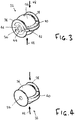
Figure 3 is a perspective view of a first embodiment of ball element for use in the top link holder ofFigures 1 and2 ; -
Figure 4 is a perspective view of a further embodiment of ball element for use in the top link holder ofFigures 1 and2 ; and -
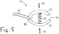
Figure 5 is a perspective view of a still further embodiment of ball element for use in the top link holder ofFigures 1 and2 . -
Figures 1 and2 show an extendibletop link 10 of a three point implement mounting linkage. At a lower end, the top link has apivot joint 12 pivotably attaching thelink 10 to the frame of a tractor (not shown). At the upper end, the top link has aquick release hook 16, which hook has amouth 18, a lever-operated retaining bolt or jaw 20, and ajaw operating lever 22. - The
pivot joint 12 allows thetop link 10 to be moved about a horizontal axis and a vertical axis. In a parked position, as shown, thetop link 10 extends upwards, and is constrained by a top link holder indicated generally at 24. The top link holder comprises anelongated body 26 pivotably attached at oneend 28 to the tractor frame. Whilst theelongated body 26 may comprise a simple metal rod, a preferred construction is a Y-shaped frame as shown, having two laterally spaced points ofattachment dampers 30 are pivotably attached at a lower end to the tractor frame and at an upper end to theelongated body 28 to damp movement of the top link holder. This is particularly required when thetop link holder 24 is not engaging thetop link 10, but is instead swung downwardly to a non-deployed position as indicated at 24A inFigure 2 . - At the free end of the
elongated body 26, a right-angled portion of the body provides a mounting for aball element 32. As shown inFigure 1 , when thetop link holder 24 is deployed, theball element 32 is received in themouth 18 of thequick release hook 16 and prevented from escaping by the lever-operated retaining bolt or jaw 20 which (if not closing it completely) reduces the size of the mouth opening to a dimension smaller than the diameter of theball element 32. -
Figures 3 to 5 show alternative embodiments ofball element 32. In the embodiments ofFigures 3 and 4 , abore 34 through the centre of abody portion 36 receives the right-angled portion of theelongated body 26 which provides a mounting support for theball element 32. Thebody portion 36 may be generally cylindrical with a central axis on thebore 34 or, as shown, the cross-section through the body portion may vary along the length of thebore 34 such as to give the body portion 36 a substantially spherical shape. At either side of the body portion 36 (at either end of the bore 34) aradial flange 38 extending out from thebore 34 provides a lip to prevent the ball element from sliding sideways out of the mouth of the hook when engaged. A laterally extendingflange 40, coplanar with the axis of thebore 34, prevents theball element 32 from rotating within the mouth of the hook. - In the embodiment of
Figure 3 , theball element 32 has a generally C-shaped cross section, with a laterally extending opening 42 following thelateral flange 40. Within the substantially hollow body portion, acentral core 44 contains thebore 34. Thecentral core 44 is supported with the outer part of the body portion by a laterally extendingfillet 46 joining the two on the opposite side of the body portion to theopening 42. Theball element 32 is formed of a resiliently deformable plastics material, such as nylon or PA6. This enables thebody portion 36 to be compressed as indicated by arrows 48 (closing up the lateral opening 42) such as to enable the ball element to be clipped into themouth 18 of thehook 16 without releasing the lever-operated retaining bolt or jaw 20: once past the bolt or jaw 20, thebody portion 36 springs back to its original diameter and cannot escape from the mouth. - In the alternative embodiment of
Figure 4 , thebody portion 36 of theball element 32 has a generally solid cross-section. In order to enable the ball element to be clipped into themouth 18 of thehook 16 without releasing the lever-operated retaining bolt or jaw 20, thebody portion 36 is formed of a rubber material, such as EPDM, having a greater degree of compressibility than the plastics material used inFigure 3 . - In the further alternative embodiment of
Figure 5 , theball element 32 has a generally C-shaped cross section, being formed of first and secondarcuate portions arcuate portions 50 is formed from the distal end of theelongated body 26 supporting theball element 32. - In the foregoing the applicants have described a link holder for constraining movement of a pivotable link terminated by a quick release hook on a vehicle or machine, such as an implement mounting linkage of an agricultural tractor, including a ball element. The hook has a mouth portion with an opening of a predetermined size when the hook is closed, and the ball element has a cross-section greater than the predetermined size and is formed of resiliently flexible material compressible to a cross-section less than the predetermined size. This enables the ball element to engage the hook without opening it.
- From reading the present disclosure, other modifications will be apparent to persons skilled in the art. Such modifications may involve other features which are already known in the field of agricultural machines and component parts thereof and which may be used instead of or in addition to features already described herein, and the scope of the invention is limited only by the following claims.
Claims (12)
- A link holder (24) for constraining movement of a pivotable link (10) terminated by a quick release hook (16) on a vehicle or machine, which hook has a mouth portion with an opening of a predetermined size when the hook is closed, wherein the link holder (24) comprises an elongated body (26) and a ball element (32) attached to a first end of the elongated body, wherein the opposite end of the elongated body (26) is attachable to the vehicle or machine, and wherein the ball element (32) has a cross-section greater than the predetermined size and is formed to be compressible to a cross-section less than the predetermined size.
- A link holder as claimed in claim 1, the ball element (32) having a generally C-shaped cross section.
- A link holder as claimed in claim 2, the ball element (32) formed of a resiliently flexible plastics material.
- A link holder as claimed in claim 3, wherein the plastics material of the ball element (32) is PA6.
- A link holder as claimed in claim 1, the ball element (32) having a generally solid cross-section and being formed of a rubber material.
- A link holder as claimed in claim 5, wherein the rubber material of the ball element (32) is EPDM.
- A link holder as claimed in claim 2, the ball element (32) comprised of first and second arcuate portions (50, 52) with one end of each pivotably connected (54) to the other and further comprising resilient means (56) positioned to urge the two arcuate portions (50, 52) apart.
- A link holder as claimed in claim 7, wherein the resilient means (56) of the ball element (32) is a spring or a body of resiliently compressible material.
- A link holder as claimed in any one of claims 1-8, wherein the elongated body (26) forms a part of the ball element (32).
- A ball element (32) for use with the link holder (24) of claim 1, having a generally C-shaped cross section wherein the ball element (32) comprises first and second arcuate portions (50, 52) with one end of each pivotably connected (54) to the other and further comprising resilient means (56) positioned to urge the two arcuate portions apart.
- A ball element as claimed in claim 10, wherein the resilient means (56) of the ball element (32) is a spring or a body of resiliently compressible material.
- An agricultural tractor having a three point implement mounting linkage including a pivotable top link (10) terminated by a quick release hook (16), and a link holder (24) as claimed in any one of claims 1-9 deployable to constrain movement of the top link when the ball element (32) is received in the mouth of the hook (16).
Applications Claiming Priority (1)
| Application Number | Priority Date | Filing Date | Title |
|---|---|---|---|
| GBGB1617032.6A GB201617032D0 (en) | 2016-10-07 | 2016-10-07 | Link holder |
Publications (2)
| Publication Number | Publication Date |
|---|---|
| EP3305050A1 true EP3305050A1 (en) | 2018-04-11 |
| EP3305050B1 EP3305050B1 (en) | 2021-10-27 |
Family
ID=57610451
Family Applications (1)
| Application Number | Title | Priority Date | Filing Date |
|---|---|---|---|
| EP17189175.7A Active EP3305050B1 (en) | 2016-10-07 | 2017-09-04 | Link holder |
Country Status (2)
| Country | Link |
|---|---|
| EP (1) | EP3305050B1 (en) |
| GB (1) | GB201617032D0 (en) |
Citations (8)
| Publication number | Priority date | Publication date | Assignee | Title |
|---|---|---|---|---|
| GB906761A (en) * | 1960-03-18 | 1962-09-26 | Ford Motor Co | Improvements in or relating to implement linkages for agricultural tractors |
| US3394948A (en) * | 1966-09-28 | 1968-07-30 | Deere & Co | Draft link construction |
| US4241935A (en) * | 1978-07-20 | 1980-12-30 | Jean Walterscheid Gmbh | Coupling hook structure for tractor hitch system |
| EP0229483A1 (en) * | 1985-12-13 | 1987-07-22 | Metallifacture Limited | Top link of a tractor linkage |
| DE3839522C1 (en) * | 1988-11-23 | 1989-11-30 | J I Case Gmbh, 4040 Neuss, De | Device for fixing the unused upper link of a hydraulic three-point mounting apparatus on farm tractors |
| US20070014497A1 (en) * | 2005-07-18 | 2007-01-18 | Deere & Company, A Delaware Corporation | Ball end for a link |
| US20100038882A1 (en) * | 2007-04-23 | 2010-02-18 | Larry Chimento | Adjustable towing hitch |
| EP2790484A1 (en) | 2011-12-15 | 2014-10-22 | AGCO International GmbH | Link holder |
-
2016
- 2016-10-07 GB GBGB1617032.6A patent/GB201617032D0/en not_active Ceased
-
2017
- 2017-09-04 EP EP17189175.7A patent/EP3305050B1/en active Active
Patent Citations (8)
| Publication number | Priority date | Publication date | Assignee | Title |
|---|---|---|---|---|
| GB906761A (en) * | 1960-03-18 | 1962-09-26 | Ford Motor Co | Improvements in or relating to implement linkages for agricultural tractors |
| US3394948A (en) * | 1966-09-28 | 1968-07-30 | Deere & Co | Draft link construction |
| US4241935A (en) * | 1978-07-20 | 1980-12-30 | Jean Walterscheid Gmbh | Coupling hook structure for tractor hitch system |
| EP0229483A1 (en) * | 1985-12-13 | 1987-07-22 | Metallifacture Limited | Top link of a tractor linkage |
| DE3839522C1 (en) * | 1988-11-23 | 1989-11-30 | J I Case Gmbh, 4040 Neuss, De | Device for fixing the unused upper link of a hydraulic three-point mounting apparatus on farm tractors |
| US20070014497A1 (en) * | 2005-07-18 | 2007-01-18 | Deere & Company, A Delaware Corporation | Ball end for a link |
| US20100038882A1 (en) * | 2007-04-23 | 2010-02-18 | Larry Chimento | Adjustable towing hitch |
| EP2790484A1 (en) | 2011-12-15 | 2014-10-22 | AGCO International GmbH | Link holder |
Also Published As
| Publication number | Publication date |
|---|---|
| GB201617032D0 (en) | 2016-11-23 |
| EP3305050B1 (en) | 2021-10-27 |
Similar Documents
| Publication | Publication Date | Title |
|---|---|---|
| US4991893A (en) | Manhole cover lifting device | |
| US7226126B1 (en) | Accessory holder for a chair | |
| US7086696B2 (en) | Vehicle seat | |
| US4909353A (en) | Tree stand | |
| US6609481B1 (en) | Game animal lift assembly for all terrain vehicles | |
| US9484616B2 (en) | Support truss for an antenna or similar device | |
| US11260939B2 (en) | Adjustable height spring-biased support pole | |
| US20110062196A1 (en) | Wagon and luggage pull | |
| US20080173852A1 (en) | Hydraulic Jack with locking mechanism | |
| US5423567A (en) | Tractor trailer fifth wheel lever/cable assembly | |
| US20140252287A1 (en) | Trailer jack plunger pin release lever system | |
| US2661563A (en) | Fishing rod holder | |
| US3865407A (en) | Hitch pin | |
| US5383298A (en) | Fishing rod holder with hook setting trigger | |
| US10226650B2 (en) | Mobile safety fall arrest cart | |
| EP3305050B1 (en) | Link holder | |
| US20240342521A1 (en) | Mobile safety fall arrest cart | |
| US7322146B1 (en) | Fishing net retraction system | |
| US4575112A (en) | Mechanized hitch for tractor or the like | |
| US10995470B2 (en) | Service pin assembly for a machine | |
| US10258020B2 (en) | Vehicle animal motion restraint | |
| US6102451A (en) | Door latch push bar assembly | |
| EP2052601A3 (en) | Angling rod support apparatus | |
| US20100224842A1 (en) | Landing jack lift | |
| EP2790484A1 (en) | Link holder |
Legal Events
| Date | Code | Title | Description |
|---|---|---|---|
| PUAI | Public reference made under article 153(3) epc to a published international application that has entered the european phase |
Free format text: ORIGINAL CODE: 0009012 |
|
| STAA | Information on the status of an ep patent application or granted ep patent |
Free format text: STATUS: THE APPLICATION HAS BEEN PUBLISHED |
|
| AK | Designated contracting states |
Kind code of ref document: A1 Designated state(s): AL AT BE BG CH CY CZ DE DK EE ES FI FR GB GR HR HU IE IS IT LI LT LU LV MC MK MT NL NO PL PT RO RS SE SI SK SM TR |
|
| AX | Request for extension of the european patent |
Extension state: BA ME |
|
| STAA | Information on the status of an ep patent application or granted ep patent |
Free format text: STATUS: REQUEST FOR EXAMINATION WAS MADE |
|
| 17P | Request for examination filed |
Effective date: 20181011 |
|
| RBV | Designated contracting states (corrected) |
Designated state(s): AL AT BE BG CH CY CZ DE DK EE ES FI FR GB GR HR HU IE IS IT LI LT LU LV MC MK MT NL NO PL PT RO RS SE SI SK SM TR |
|
| GRAP | Despatch of communication of intention to grant a patent |
Free format text: ORIGINAL CODE: EPIDOSNIGR1 |
|
| STAA | Information on the status of an ep patent application or granted ep patent |
Free format text: STATUS: GRANT OF PATENT IS INTENDED |
|
| RIC1 | Information provided on ipc code assigned before grant |
Ipc: A01B 59/00 20060101AFI20210526BHEP |
|
| INTG | Intention to grant announced |
Effective date: 20210609 |
|
| GRAS | Grant fee paid |
Free format text: ORIGINAL CODE: EPIDOSNIGR3 |
|
| GRAA | (expected) grant |
Free format text: ORIGINAL CODE: 0009210 |
|
| STAA | Information on the status of an ep patent application or granted ep patent |
Free format text: STATUS: THE PATENT HAS BEEN GRANTED |
|
| AK | Designated contracting states |
Kind code of ref document: B1 Designated state(s): AL AT BE BG CH CY CZ DE DK EE ES FI FR GB GR HR HU IE IS IT LI LT LU LV MC MK MT NL NO PL PT RO RS SE SI SK SM TR |
|
| REG | Reference to a national code |
Ref country code: GB Ref legal event code: FG4D |
|
| REG | Reference to a national code |
Ref country code: CH Ref legal event code: EP |
|
| REG | Reference to a national code |
Ref country code: AT Ref legal event code: REF Ref document number: 1440992 Country of ref document: AT Kind code of ref document: T Effective date: 20211115 |
|
| REG | Reference to a national code |
Ref country code: DE Ref legal event code: R096 Ref document number: 602017048152 Country of ref document: DE |
|
| REG | Reference to a national code |
Ref country code: IE Ref legal event code: FG4D |
|
| REG | Reference to a national code |
Ref country code: LT Ref legal event code: MG9D |
|
| REG | Reference to a national code |
Ref country code: NL Ref legal event code: MP Effective date: 20211027 |
|
| REG | Reference to a national code |
Ref country code: AT Ref legal event code: MK05 Ref document number: 1440992 Country of ref document: AT Kind code of ref document: T Effective date: 20211027 |
|
| PG25 | Lapsed in a contracting state [announced via postgrant information from national office to epo] |
Ref country code: RS Free format text: LAPSE BECAUSE OF FAILURE TO SUBMIT A TRANSLATION OF THE DESCRIPTION OR TO PAY THE FEE WITHIN THE PRESCRIBED TIME-LIMIT Effective date: 20211027 Ref country code: LT Free format text: LAPSE BECAUSE OF FAILURE TO SUBMIT A TRANSLATION OF THE DESCRIPTION OR TO PAY THE FEE WITHIN THE PRESCRIBED TIME-LIMIT Effective date: 20211027 Ref country code: FI Free format text: LAPSE BECAUSE OF FAILURE TO SUBMIT A TRANSLATION OF THE DESCRIPTION OR TO PAY THE FEE WITHIN THE PRESCRIBED TIME-LIMIT Effective date: 20211027 Ref country code: BG Free format text: LAPSE BECAUSE OF FAILURE TO SUBMIT A TRANSLATION OF THE DESCRIPTION OR TO PAY THE FEE WITHIN THE PRESCRIBED TIME-LIMIT Effective date: 20220127 Ref country code: AT Free format text: LAPSE BECAUSE OF FAILURE TO SUBMIT A TRANSLATION OF THE DESCRIPTION OR TO PAY THE FEE WITHIN THE PRESCRIBED TIME-LIMIT Effective date: 20211027 |
|
| PG25 | Lapsed in a contracting state [announced via postgrant information from national office to epo] |
Ref country code: IS Free format text: LAPSE BECAUSE OF FAILURE TO SUBMIT A TRANSLATION OF THE DESCRIPTION OR TO PAY THE FEE WITHIN THE PRESCRIBED TIME-LIMIT Effective date: 20220227 Ref country code: SE Free format text: LAPSE BECAUSE OF FAILURE TO SUBMIT A TRANSLATION OF THE DESCRIPTION OR TO PAY THE FEE WITHIN THE PRESCRIBED TIME-LIMIT Effective date: 20211027 Ref country code: PT Free format text: LAPSE BECAUSE OF FAILURE TO SUBMIT A TRANSLATION OF THE DESCRIPTION OR TO PAY THE FEE WITHIN THE PRESCRIBED TIME-LIMIT Effective date: 20220228 Ref country code: PL Free format text: LAPSE BECAUSE OF FAILURE TO SUBMIT A TRANSLATION OF THE DESCRIPTION OR TO PAY THE FEE WITHIN THE PRESCRIBED TIME-LIMIT Effective date: 20211027 Ref country code: NO Free format text: LAPSE BECAUSE OF FAILURE TO SUBMIT A TRANSLATION OF THE DESCRIPTION OR TO PAY THE FEE WITHIN THE PRESCRIBED TIME-LIMIT Effective date: 20220127 Ref country code: NL Free format text: LAPSE BECAUSE OF FAILURE TO SUBMIT A TRANSLATION OF THE DESCRIPTION OR TO PAY THE FEE WITHIN THE PRESCRIBED TIME-LIMIT Effective date: 20211027 Ref country code: LV Free format text: LAPSE BECAUSE OF FAILURE TO SUBMIT A TRANSLATION OF THE DESCRIPTION OR TO PAY THE FEE WITHIN THE PRESCRIBED TIME-LIMIT Effective date: 20211027 Ref country code: HR Free format text: LAPSE BECAUSE OF FAILURE TO SUBMIT A TRANSLATION OF THE DESCRIPTION OR TO PAY THE FEE WITHIN THE PRESCRIBED TIME-LIMIT Effective date: 20211027 Ref country code: GR Free format text: LAPSE BECAUSE OF FAILURE TO SUBMIT A TRANSLATION OF THE DESCRIPTION OR TO PAY THE FEE WITHIN THE PRESCRIBED TIME-LIMIT Effective date: 20220128 Ref country code: ES Free format text: LAPSE BECAUSE OF FAILURE TO SUBMIT A TRANSLATION OF THE DESCRIPTION OR TO PAY THE FEE WITHIN THE PRESCRIBED TIME-LIMIT Effective date: 20211027 |
|
| REG | Reference to a national code |
Ref country code: DE Ref legal event code: R097 Ref document number: 602017048152 Country of ref document: DE |
|
| PG25 | Lapsed in a contracting state [announced via postgrant information from national office to epo] |
Ref country code: SM Free format text: LAPSE BECAUSE OF FAILURE TO SUBMIT A TRANSLATION OF THE DESCRIPTION OR TO PAY THE FEE WITHIN THE PRESCRIBED TIME-LIMIT Effective date: 20211027 Ref country code: SK Free format text: LAPSE BECAUSE OF FAILURE TO SUBMIT A TRANSLATION OF THE DESCRIPTION OR TO PAY THE FEE WITHIN THE PRESCRIBED TIME-LIMIT Effective date: 20211027 Ref country code: RO Free format text: LAPSE BECAUSE OF FAILURE TO SUBMIT A TRANSLATION OF THE DESCRIPTION OR TO PAY THE FEE WITHIN THE PRESCRIBED TIME-LIMIT Effective date: 20211027 Ref country code: EE Free format text: LAPSE BECAUSE OF FAILURE TO SUBMIT A TRANSLATION OF THE DESCRIPTION OR TO PAY THE FEE WITHIN THE PRESCRIBED TIME-LIMIT Effective date: 20211027 Ref country code: DK Free format text: LAPSE BECAUSE OF FAILURE TO SUBMIT A TRANSLATION OF THE DESCRIPTION OR TO PAY THE FEE WITHIN THE PRESCRIBED TIME-LIMIT Effective date: 20211027 Ref country code: CZ Free format text: LAPSE BECAUSE OF FAILURE TO SUBMIT A TRANSLATION OF THE DESCRIPTION OR TO PAY THE FEE WITHIN THE PRESCRIBED TIME-LIMIT Effective date: 20211027 |
|
| PLBE | No opposition filed within time limit |
Free format text: ORIGINAL CODE: 0009261 |
|
| STAA | Information on the status of an ep patent application or granted ep patent |
Free format text: STATUS: NO OPPOSITION FILED WITHIN TIME LIMIT |
|
| 26N | No opposition filed |
Effective date: 20220728 |
|
| PG25 | Lapsed in a contracting state [announced via postgrant information from national office to epo] |
Ref country code: AL Free format text: LAPSE BECAUSE OF FAILURE TO SUBMIT A TRANSLATION OF THE DESCRIPTION OR TO PAY THE FEE WITHIN THE PRESCRIBED TIME-LIMIT Effective date: 20211027 |
|
| PG25 | Lapsed in a contracting state [announced via postgrant information from national office to epo] |
Ref country code: SI Free format text: LAPSE BECAUSE OF FAILURE TO SUBMIT A TRANSLATION OF THE DESCRIPTION OR TO PAY THE FEE WITHIN THE PRESCRIBED TIME-LIMIT Effective date: 20211027 |
|
| PG25 | Lapsed in a contracting state [announced via postgrant information from national office to epo] |
Ref country code: MC Free format text: LAPSE BECAUSE OF FAILURE TO SUBMIT A TRANSLATION OF THE DESCRIPTION OR TO PAY THE FEE WITHIN THE PRESCRIBED TIME-LIMIT Effective date: 20211027 |
|
| REG | Reference to a national code |
Ref country code: CH Ref legal event code: PL |
|
| GBPC | Gb: european patent ceased through non-payment of renewal fee |
Effective date: 20220904 |
|
| REG | Reference to a national code |
Ref country code: BE Ref legal event code: MM Effective date: 20220930 |
|
| P01 | Opt-out of the competence of the unified patent court (upc) registered |
Effective date: 20230518 |
|
| PG25 | Lapsed in a contracting state [announced via postgrant information from national office to epo] |
Ref country code: LU Free format text: LAPSE BECAUSE OF NON-PAYMENT OF DUE FEES Effective date: 20220904 |
|
| PG25 | Lapsed in a contracting state [announced via postgrant information from national office to epo] |
Ref country code: LI Free format text: LAPSE BECAUSE OF NON-PAYMENT OF DUE FEES Effective date: 20220930 Ref country code: IE Free format text: LAPSE BECAUSE OF NON-PAYMENT OF DUE FEES Effective date: 20220904 Ref country code: CH Free format text: LAPSE BECAUSE OF NON-PAYMENT OF DUE FEES Effective date: 20220930 |
|
| PG25 | Lapsed in a contracting state [announced via postgrant information from national office to epo] |
Ref country code: BE Free format text: LAPSE BECAUSE OF NON-PAYMENT OF DUE FEES Effective date: 20220930 |
|
| PG25 | Lapsed in a contracting state [announced via postgrant information from national office to epo] |
Ref country code: GB Free format text: LAPSE BECAUSE OF NON-PAYMENT OF DUE FEES Effective date: 20220904 |
|
| PG25 | Lapsed in a contracting state [announced via postgrant information from national office to epo] |
Ref country code: HU Free format text: LAPSE BECAUSE OF FAILURE TO SUBMIT A TRANSLATION OF THE DESCRIPTION OR TO PAY THE FEE WITHIN THE PRESCRIBED TIME-LIMIT; INVALID AB INITIO Effective date: 20170904 |
|
| PG25 | Lapsed in a contracting state [announced via postgrant information from national office to epo] |
Ref country code: CY Free format text: LAPSE BECAUSE OF FAILURE TO SUBMIT A TRANSLATION OF THE DESCRIPTION OR TO PAY THE FEE WITHIN THE PRESCRIBED TIME-LIMIT Effective date: 20211027 |
|
| PG25 | Lapsed in a contracting state [announced via postgrant information from national office to epo] |
Ref country code: MK Free format text: LAPSE BECAUSE OF FAILURE TO SUBMIT A TRANSLATION OF THE DESCRIPTION OR TO PAY THE FEE WITHIN THE PRESCRIBED TIME-LIMIT Effective date: 20211027 |
|
| PG25 | Lapsed in a contracting state [announced via postgrant information from national office to epo] |
Ref country code: MT Free format text: LAPSE BECAUSE OF FAILURE TO SUBMIT A TRANSLATION OF THE DESCRIPTION OR TO PAY THE FEE WITHIN THE PRESCRIBED TIME-LIMIT Effective date: 20211027 |
|
| PGFP | Annual fee paid to national office [announced via postgrant information from national office to epo] |
Ref country code: IT Payment date: 20240918 Year of fee payment: 8 |
|
| PGFP | Annual fee paid to national office [announced via postgrant information from national office to epo] |
Ref country code: DE Payment date: 20250919 Year of fee payment: 9 |
|
| PGFP | Annual fee paid to national office [announced via postgrant information from national office to epo] |
Ref country code: FR Payment date: 20250922 Year of fee payment: 9 |
|
| REG | Reference to a national code |
Ref country code: DE Ref legal event code: R084 Ref document number: 602017048152 Country of ref document: DE |
|
| PG25 | Lapsed in a contracting state [announced via postgrant information from national office to epo] |
Ref country code: TR Free format text: LAPSE BECAUSE OF FAILURE TO SUBMIT A TRANSLATION OF THE DESCRIPTION OR TO PAY THE FEE WITHIN THE PRESCRIBED TIME-LIMIT Effective date: 20211027 |
|
| PG25 | Lapsed in a contracting state [announced via postgrant information from national office to epo] |
Ref country code: IT Free format text: LAPSE BECAUSE OF NON-PAYMENT OF DUE FEES Effective date: 20250904 |