EP3302802B1 - Sample processing devices, and methods of use thereof - Google Patents
Sample processing devices, and methods of use thereof Download PDFInfo
- Publication number
- EP3302802B1 EP3302802B1 EP16736297.9A EP16736297A EP3302802B1 EP 3302802 B1 EP3302802 B1 EP 3302802B1 EP 16736297 A EP16736297 A EP 16736297A EP 3302802 B1 EP3302802 B1 EP 3302802B1
- Authority
- EP
- European Patent Office
- Prior art keywords
- tube
- examples
- sample
- cap
- processing device
- Prior art date
- Legal status (The legal status is an assumption and is not a legal conclusion. Google has not performed a legal analysis and makes no representation as to the accuracy of the status listed.)
- Active
Links
Images











Classifications
-
- B—PERFORMING OPERATIONS; TRANSPORTING
- B01—PHYSICAL OR CHEMICAL PROCESSES OR APPARATUS IN GENERAL
- B01L—CHEMICAL OR PHYSICAL LABORATORY APPARATUS FOR GENERAL USE
- B01L3/00—Containers or dishes for laboratory use, e.g. laboratory glassware; Droppers
- B01L3/56—Labware specially adapted for transferring fluids
- B01L3/563—Joints or fittings; Separable fluid transfer means to transfer fluids between at least two containers, e.g. connectors
- B01L3/5635—Joints or fittings; Separable fluid transfer means to transfer fluids between at least two containers, e.g. connectors connecting two containers face to face, e.g. comprising a filter
-
- B—PERFORMING OPERATIONS; TRANSPORTING
- B01—PHYSICAL OR CHEMICAL PROCESSES OR APPARATUS IN GENERAL
- B01L—CHEMICAL OR PHYSICAL LABORATORY APPARATUS FOR GENERAL USE
- B01L3/00—Containers or dishes for laboratory use, e.g. laboratory glassware; Droppers
- B01L3/50—Containers for the purpose of retaining a material to be analysed, e.g. test tubes
-
- B—PERFORMING OPERATIONS; TRANSPORTING
- B01—PHYSICAL OR CHEMICAL PROCESSES OR APPARATUS IN GENERAL
- B01L—CHEMICAL OR PHYSICAL LABORATORY APPARATUS FOR GENERAL USE
- B01L3/00—Containers or dishes for laboratory use, e.g. laboratory glassware; Droppers
- B01L3/50—Containers for the purpose of retaining a material to be analysed, e.g. test tubes
- B01L3/502—Containers for the purpose of retaining a material to be analysed, e.g. test tubes with fluid transport, e.g. in multi-compartment structures
-
- B—PERFORMING OPERATIONS; TRANSPORTING
- B01—PHYSICAL OR CHEMICAL PROCESSES OR APPARATUS IN GENERAL
- B01L—CHEMICAL OR PHYSICAL LABORATORY APPARATUS FOR GENERAL USE
- B01L3/00—Containers or dishes for laboratory use, e.g. laboratory glassware; Droppers
- B01L3/50—Containers for the purpose of retaining a material to be analysed, e.g. test tubes
- B01L3/508—Rigid containers without fluid transport within
-
- B—PERFORMING OPERATIONS; TRANSPORTING
- B01—PHYSICAL OR CHEMICAL PROCESSES OR APPARATUS IN GENERAL
- B01L—CHEMICAL OR PHYSICAL LABORATORY APPARATUS FOR GENERAL USE
- B01L3/00—Containers or dishes for laboratory use, e.g. laboratory glassware; Droppers
- B01L3/56—Labware specially adapted for transferring fluids
- B01L3/561—Tubes; Conduits
-
- C—CHEMISTRY; METALLURGY
- C12—BIOCHEMISTRY; BEER; SPIRITS; WINE; VINEGAR; MICROBIOLOGY; ENZYMOLOGY; MUTATION OR GENETIC ENGINEERING
- C12M—APPARATUS FOR ENZYMOLOGY OR MICROBIOLOGY; APPARATUS FOR CULTURING MICROORGANISMS FOR PRODUCING BIOMASS, FOR GROWING CELLS OR FOR OBTAINING FERMENTATION OR METABOLIC PRODUCTS, i.e. BIOREACTORS OR FERMENTERS
- C12M45/00—Means for pre-treatment of biological substances
- C12M45/06—Means for pre-treatment of biological substances by chemical means or hydrolysis
-
- C—CHEMISTRY; METALLURGY
- C12—BIOCHEMISTRY; BEER; SPIRITS; WINE; VINEGAR; MICROBIOLOGY; ENZYMOLOGY; MUTATION OR GENETIC ENGINEERING
- C12N—MICROORGANISMS OR ENZYMES; COMPOSITIONS THEREOF; PROPAGATING, PRESERVING, OR MAINTAINING MICROORGANISMS; MUTATION OR GENETIC ENGINEERING; CULTURE MEDIA
- C12N15/00—Mutation or genetic engineering; DNA or RNA concerning genetic engineering, vectors, e.g. plasmids, or their isolation, preparation or purification; Use of hosts therefor
- C12N15/09—Recombinant DNA-technology
- C12N15/10—Processes for the isolation, preparation or purification of DNA or RNA
- C12N15/1003—Extracting or separating nucleic acids from biological samples, e.g. pure separation or isolation methods; Conditions, buffers or apparatuses therefor
- C12N15/1017—Extracting or separating nucleic acids from biological samples, e.g. pure separation or isolation methods; Conditions, buffers or apparatuses therefor by filtration, e.g. using filters, frits, membranes
-
- B—PERFORMING OPERATIONS; TRANSPORTING
- B01—PHYSICAL OR CHEMICAL PROCESSES OR APPARATUS IN GENERAL
- B01L—CHEMICAL OR PHYSICAL LABORATORY APPARATUS FOR GENERAL USE
- B01L2200/00—Solutions for specific problems relating to chemical or physical laboratory apparatus
- B01L2200/02—Adapting objects or devices to another
- B01L2200/026—Fluid interfacing between devices or objects, e.g. connectors, inlet details
-
- B—PERFORMING OPERATIONS; TRANSPORTING
- B01—PHYSICAL OR CHEMICAL PROCESSES OR APPARATUS IN GENERAL
- B01L—CHEMICAL OR PHYSICAL LABORATORY APPARATUS FOR GENERAL USE
- B01L2200/00—Solutions for specific problems relating to chemical or physical laboratory apparatus
- B01L2200/06—Fluid handling related problems
- B01L2200/0631—Purification arrangements, e.g. solid phase extraction [SPE]
-
- B—PERFORMING OPERATIONS; TRANSPORTING
- B01—PHYSICAL OR CHEMICAL PROCESSES OR APPARATUS IN GENERAL
- B01L—CHEMICAL OR PHYSICAL LABORATORY APPARATUS FOR GENERAL USE
- B01L2300/00—Additional constructional details
- B01L2300/02—Identification, exchange or storage of information
- B01L2300/021—Identification, e.g. bar codes
-
- B—PERFORMING OPERATIONS; TRANSPORTING
- B01—PHYSICAL OR CHEMICAL PROCESSES OR APPARATUS IN GENERAL
- B01L—CHEMICAL OR PHYSICAL LABORATORY APPARATUS FOR GENERAL USE
- B01L2300/00—Additional constructional details
- B01L2300/04—Closures and closing means
- B01L2300/041—Connecting closures to device or container
- B01L2300/042—Caps; Plugs
-
- B—PERFORMING OPERATIONS; TRANSPORTING
- B01—PHYSICAL OR CHEMICAL PROCESSES OR APPARATUS IN GENERAL
- B01L—CHEMICAL OR PHYSICAL LABORATORY APPARATUS FOR GENERAL USE
- B01L2300/00—Additional constructional details
- B01L2300/04—Closures and closing means
- B01L2300/041—Connecting closures to device or container
- B01L2300/044—Connecting closures to device or container pierceable, e.g. films, membranes
-
- B—PERFORMING OPERATIONS; TRANSPORTING
- B01—PHYSICAL OR CHEMICAL PROCESSES OR APPARATUS IN GENERAL
- B01L—CHEMICAL OR PHYSICAL LABORATORY APPARATUS FOR GENERAL USE
- B01L2300/00—Additional constructional details
- B01L2300/06—Auxiliary integrated devices, integrated components
- B01L2300/0681—Filter
-
- B—PERFORMING OPERATIONS; TRANSPORTING
- B01—PHYSICAL OR CHEMICAL PROCESSES OR APPARATUS IN GENERAL
- B01L—CHEMICAL OR PHYSICAL LABORATORY APPARATUS FOR GENERAL USE
- B01L2300/00—Additional constructional details
- B01L2300/08—Geometry, shape and general structure
- B01L2300/0832—Geometry, shape and general structure cylindrical, tube shaped
-
- B—PERFORMING OPERATIONS; TRANSPORTING
- B01—PHYSICAL OR CHEMICAL PROCESSES OR APPARATUS IN GENERAL
- B01L—CHEMICAL OR PHYSICAL LABORATORY APPARATUS FOR GENERAL USE
- B01L2400/00—Moving or stopping fluids
- B01L2400/04—Moving fluids with specific forces or mechanical means
- B01L2400/0403—Moving fluids with specific forces or mechanical means specific forces
- B01L2400/0457—Moving fluids with specific forces or mechanical means specific forces passive flow or gravitation
Definitions
- the processing of raw biological samples for extraction of DNA for genetic profiling usually requires multiple vessels that are used through a plurality of processing steps.
- separate vessels are used for one or more different biochemical analysis steps, including taking the sample, disrupting the sample with chemical or mechanical means, extracting DNA from the sample, and analyzing the sample.
- the introduction of multiple surfaces and transfer of samples from one vessel to another can increase the risk of contamination that can introduce errors during the downstream sample analysis step. Accordingly, there is a need to integrate and miniaturize various sample processing steps into a unitary or modular device, to significantly reduce or eliminate the need to transfer biological samples between multiple separate vessels.
- a modular design can increase the efficiency of extracting nucleic acids from tissue samples, and increase efficiency by largely eliminating the need to transfer reactants between separate reaction vessels to perform each step of the extraction process. Furthermore, integration of the device with external automation equipment modular designs can allow the extraction process to be performed with only one action from the user, thereby enabling the process to be fully automated after the user initiates the extraction process.
- US2003/134432A1 describes a system for producing a library of oligomer comprising at least two monomers in a positionally determined array comprise a plurality of synthesis supports, a first plurality of support carriers wherein each carrier has a uniform array of distinct support holding positions for the synthesis supports; means for contacting each array of synthesis supports with a different monomer to provide a first chemical transformation of the synthesis supports; a second plurality of support carriers wherein each carrier has a uniform array of distinct support holding positions for receiving the chemically transformed synthesis supports contained in the first plurality of support carriers; transfer apparatus for transferring a selected row or column of synthesis supports from each of the first plurality of carriers to each of the second plurality of carriers to enable the supports in the second to undergo at least a second chemical transformation; and whereby each support position in each carrier identifies the chemical compound thereon.
- tissue dissociators configured to disrupt a biological tissue sample. Aspects of the tissue dissociators may include a housing having a distal end and a proximal end, a cutting blade positioned at the distal end of the housing and a tissue actuator configured to be displaced along a longitudinal axis within the housing. Also described are methods of using the tissue dissociators, as well as kits including the tissue dissociators.
- US2007/014690A1 describes devices and methods for homogenization, processing, detection, and analysis of biological samples such as insects, fungi, bacteria, and plant and animal tissues. Multiple chambers in these devices permit different processing functions to be carried out at each stage, such that the resulting homogenized product can be further processed, purified, analyzed, and/or biomolecules such as metabolites, proteins and nucleic acids, or pharmaceutical products can be detected.
- the device can be used in a hydrostatic pressure apparatus, in which different activities, i.e. incubations, addition or renewal of reagent, and generation and detection of signal can be carried out in the appropriate chamber.
- the method improves the preservation of biomolecules from chemical and enzymatic degradation relative to conventional means. Additionally, this method enables automated sample preparation and analytical processes.
- the present invention comprises a sample processing device and method as defined in the claims.
- a filter kit comprising a center portion, and a first connection portion coupled to a first side of the center portion, where the first connection portion is coupled to a first tube containing a buffer solution. Further, a second connection portion is coupled to a second side of the center portion, where the second connection portion is coupled to a second tube containing a lyophilized master mix. Further, the filter cap includes a first filter at least partially located in the first connection portion, and a second filter at least partially located in the second connection portion. In some further examples, the filter cap comprises a third filter at least partially located in the center portion of the filter cap.
- a tube kit comprising a first tube containing a buffer solution, and a second tube containing a lyophilized master mix.
- the kit also includes a filter cap comprising a center portion, a first connection portion coupled to a first side of the center portion, and a second connection portion coupled to a second side of the center portion. Further, the kit also includes a first filter at least partially located in the first connection portion, and a second filter at least partially located in the second connection portion.
- first connection portion of the filter cap is configured to be positioned in a cavity in the first tube to form at least a partial mechanical seal with the first tube.
- second connection portion of the filter cap is configured to be positioned in a cavity in the second tube to form at least a partial mechanical seal with the second tube.
- Some examples include a first adhesive on the first side of the center portion of the filter cap around the first connection portion, where the first adhesive is configured to form a seal between the filter cap and the first tube. Further, a second adhesive on the second side of the center portion of the filter cap around the second connection portion is configured to form a seal between the filter cap and the second tube.
- a method comprising placing a biological sample in a first tube that is preloaded with a buffer solution, where a biological sample and buffer solution mixture is formed. Further, the method includes positioning a filter cap in the first tube, positioning a second tube on the filter cap, flipping the first tube, the filter cap, and the second cap, and filtering the biological sample and buffer solution mixture with the filter cap as it flows from the first tube to the second tube. Some further examples include positioning the filter cap in the first tube that includes positioning a first connection portion of the filter cap in the first tube. Some other examples include positioning a second tube on the filter cap that includes positioning a second tube on a second connection portion of the filter cap.
- a tube kit comprising a first tube containing a buffer solution, where there is an opening at a first end of the first tube and a seal across a second end of the first tube.
- the tube kit comprises a second tube containing a lyophilized master mix, and a lid with a tip coupled to the lid, where the second end of the first tube is configured to form a seal with the first end of the second tube, and where the tip coupled to the lid is configured to puncture the seal on the second end of the first tube as the lid is placed on the first tube.
- the first tube sits in the second tube. In some further examples, the first tube clips onto the second tube. In other examples, the lid has a bulb top. In some further examples, the second tube includes a filter.
- a method comprising adding a biological sample to a first tube containing a buffer solution, where the biological sample is added through an opening at a first end of the first tube, and positioning a second end of the first tube in a second tube, puncturing a seal on the second end of the first tube with a tip coupled to a lid, and positioning the lid on the first tube to form a seal between the lid and the first tube.
- an inline sample processing device comprising a first chamber configured to receive a tissue sample and a nucleic acid extraction reagent, where the first chamber is configured to permit the tissue sample to be pulverized.
- the method includes a second chamber in flow communication with the first chamber that is configured to receive the extraction reagent and a portion of the pulverized tissue sample.
- the device includes a first separation element disposed between the first chamber and the second chamber and configured to permit a portion of the pulverized tissue sample and the extraction reagent to flow from the first chamber to the second chamber.
- a third chamber is in flow communication with the second chamber, and has a plurality of ports configured to allow a reagent to be delivered to the third chamber, and a second separation element is disposed between the second chamber and the third chamber and is configured to substantially prevent the pulverized tissue from entering the third chamber.
- a sample processing device for pulverization and denaturation comprising a hollow cylindrical portion, a hollow tapered portion, a first cap for covering an end of the cylindrical portion, and a second cap for covering an end of the tapered portion.
- the device can include a plurality of ribs extending along the cylindrical portion, a ring at an end of the plurality of ribs where the cylindrical portion meets the tapered portion, and a pulverizer contained within the cylindrical portion between the ring and the first cap.
- the pulverizer is cylindrical or spherical. In some further examples, the pulverizer is glass, ceramic, stainless steel, or a non-reactive polymer. In some other examples, the plurality of ribs prevents the pulverizer from touching sides of the sample processing device and allows the pulverizer to slide within the cylindrical portion. In some further examples, the ring prevents the pulverizer from entering the tapered portion of the sample processing device.
- a method for pulverizing and denaturing a crude sample comprising placing a pulverizer in a sample processing device.
- the device can comprise a cylindrical portion, a tapered portion, and a plurality of ribs extending along the cylindrical portion, and a ring at an end of the plurality of ribs where the cylindrical portion meets the tapered portion.
- the method can include placing the crude sample in the cylindrical portion of the sample processing device, sealing the sample processing device, and shaking the sample processing device such that the pulverizer macerates the crude sample to create a pulverized sample.
- the method can include adding a denaturing agent into the tapered portion of the sample processing device, sealing the sample processing device, and shaking the sample processing device such that the denaturing agent denatures DNA within the pulverized sample to create a denatured sample.
- Some examples comprise transferring the denatured sample into a testing vessel.
- Other examples include testing the denatured sample in the sample processing device.
- a sample processing device comprising a tube comprising a removable basket with a grid and a plurality of tabs that hang over an edge of the tube, a barcode, and a cap comprising a ring-shaped punch edge for punching a sample out of a crude biological material, and a plurality of fingers or teeth for forcing the sample through the grid of the removable basket in the tube.
- the cap snaps onto the tube. In other examples, the cap twists onto the tube. Some further examples include a sample processing liquid. In other examples, the sample processing liquid is a lysis buffer in the tube. In some further examples, the sample processing liquid is sodium hydroxide contained within a pouch in the tube or the cap. In other examples, the tube further comprises a permeable layer adjacent to the sodium hydroxide pouch. In some examples, the cap further comprises a piercer. In some further examples, the cap further comprises a septum.
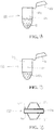
- FIG. 1A is side view of first tube 100.
- the first tube 100 includes body 102 at least partially enclosing or forming the cavity 104, and a lid 106.
- the lid 106 can be coupled or tethered to the body 102.
- the lid 106 can be detached from or independent from the body 102, and later coupled to the body 102 when required.
- the lid 106 can be sized to be positioned in the cavity 104 to at least partially seal the first tube 100.
- the lid 106 can be coupled to the body 102 using any conventional coupling.
- FIG. IB is a side view of second tube 110.
- the second tube 110 shown in FIG. IB can include a body 112, cavity 114, and a lid 116.
- the lid 116 can be coupled to the body 112.
- the lid 116 can be detached from the body 112, and later coupled to the body 112 when required.
- the lid 116 can be sized to be positioned in the cavity 114 to at least partially seal the first tube 110.
- the lid 116 can be coupled to the body 112 using any conventional coupling.
- body 102 and/or body 112 can be used without a lid (i.e., lid 106 and/or lid 116 can be absent).
- the first tube 100 and/or the second tube 110 and include a generally rounded or curved end.
- the first tube 100 and/or the second tube 110 can comprise a closed end that comprises a flat or square end.
- the first tube 100 can contain a volume of buffer solution B in cavity 104 of the body 102.
- the volume of buffer solution B can at least partially fill the first tube 100 (shown in this non- limiting example as filling the closed end of the first tube 100 including the rounded or curved portion).
- more or less volume of buffer solution B can be added or included in the first tube 100 (e.g., in a kit).
- the second tube 110 can contain a lyophilized master mix LMM in cavity 114 of the body 112.
- the volume of lyophilized master mix LMM can at least partially fill the second tube 110 (shown in this non-limiting example as at least partially filling the closed end of the second tube 110 including the rounded or curved portion). In other examples, more or less volume of lyophilized master mix LMM can be added or included in the second tube 110.
- FIG. 1C is a side view of filter cap 120 in accordance with some examples.
- the filter cap 120 can include a first connection portion 122, a second connection portion 124, and a center portion 126 positioned substantially between the first connection portion 122 and the second connection portion 124.
- the filter cap 120 can be coupled with the first tube 100 and/or the second tube 110 and used to perform one or more filtering functions of material within the tubes 100, 110.
- the first connection portion 122 can be coupled to a first side of center portion 126 and second connection portion 124 is coupled to a second side of center portion 126.
- first connection portion 122, and/or the second connection portion 124, and/or the center portion 126 can include one or more filters.
- first connection portion 122 of filter cap 120 can be sized to be positioned in cavity 104 of the first tube 100 to form at least a partial seal between the filter cap 120 and the first tube 100.
- second connection portion 124 of filter cap 120 can be sized to be positioned in cavity 114 of the second tube 110 to form at least a partial seal between filter cap 120 and second tube 110.
- the filter cap 120 can include a first adhesive 128 on the first side of center portion 126 around first connection portion 122, and a second adhesive 129 on the second side of center portion 126 around the second connection portion 124.
- the first adhesive 128 and second adhesive 129 can hold the filter cap 120 in position in the first tube 100 and the second tube 110 when the filter cap 120 is positioned in the first tube 100 and second tube 110.
- the positioning of the filter cap 120 with adhesives 128, 129 can prevent leakage between the filter cap 120 and the first tube 100 and second tube 110.
- the first adhesive 128 and/or second adhesive 129 can be omitted, and the filter cap 120 can at least partially seal against first tube 100 and second tube 110 using a conventional mechanical seal.
- FIG. 2 is a flow chart showing the steps of preparing biological sample S for testing.
- FIG. 2 includes steps 130, 132, 134, 136, and 138.
- the steps of preparing biological sample S for testing can include the order as shown.
- any of the steps 130, 132, 134, 136, 138 can proceed in a different order than shown.
- any of the steps 130, 132, 134, 136, 138 can be included, omitted, or repeated.
- the filter cap 120 can be positioned between the first tube 100 and the second tube 110 to enable filtering a biological sample.
- FIGS. 3-5 show steps 132, 134, and 138, respectively.
- FIG. 3 is a side view of filter cap 120 positioned on first tube 100.
- FIG. 4 is a side view of filter cap 120 positioned between first tube 100 and second tube 110.
- step 130 can include placing biological sample S in a first tube 100 that contains buffer solution B.
- first tube 100 can have buffer solution B placed or pre-loaded in first tube 100 prior to the collection of a biological sample S.
- the buffer solution B in the first tube 100 can vary depending on what biological sample S is to be tested.
- the biological sample S can be pipetted into the first tube 100 to mix with buffer solution B in the first tube 100. In some examples, this can create a biological sample S and buffer solution B mixture (S+B). In some examples, the biological sample and buffer solution mixture S+B can be heated in the first tube 100 if needed.
- step 132 can include positioning a first connection portion 122 of filter cap 120 in first tube 100, as seen in FIG. 3 .
- the first connection portion 122 of filter cap 120 can form at least a partial seal with first tube 100.
- first adhesive 128 can be applied to the first side of center portion 126 of filter cap 120 around the first connection portion 122 to strengthen the seal between filter cap 120 and first tube 100. Further, in some examples, the first adhesive 128 can help to prevent biological sample and buffer solution mixture S+B from leaking out of first tube 100.
- step 134 can include positioning the second tube 110 on the second connection portion 124 of filter cap 120, as seen in FIG. 4 .
- the second tube 110 can have lyophilized master mix LMM placed or pre-loaded in the second tube 110 prior to the collection of biological sample S.
- lyophilized master mix LMM preloaded in second tube 110 can vary depending on what biological sample S is to be tested.
- the second connection portion 124 of filter cap 120 can form at least a partial seal with the second tube 110.
- the second adhesive 129 can be applied to the second side of center portion 126 of filter cap 120 around second connection portion 124 to strengthen the seal between filter cap 120 and second tube 110.
- step 138 can include filtering the biological sample and buffer solution mixture S+B through filter cap 120.
- step 136 can include rotating, turning and/or flipping the first tube 100, filter cap 120, and second tube 110.
- the rotating, turning and/or flipping the first tube 100, filter cap 120, and second tube 110 can include a single rotation, turn or flip.
- the rotating, turning and/or flipping the first tube 100, filter cap 120, and second tube 110 can include multiple or repeated rotating, turning and/or flipping.
- the action of rotating, turning and/or flipping can agitate the contents of the first tube 100 and/or the second tube 110.
- this movement can allow the biological sample and buffer solution mixture S+B to flow through the filter cap 120 into the second tube 110.
- the second adhesive 129 that is positioned between filter cap 120 and second tube 110 can help prevent biological sample and buffer solution mixture S+B from leaking out of filter cap 120 and second tube 100 as the biological sample and buffer solution mixture S+B flows through the filter cap 120 into the second tube 110.
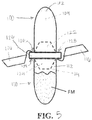
- FIG. 5 is a side view of filter cap 120 positioned between first tube 100 and second tube 110. In this non-limiting example, the positions of the first tube 100 and second tube 110 are flipped about 180° than that illustrated in FIG. 4 , and the biological sample and buffer solution mixture S+B has exited the first tube 100 and entered the second tube 110 through filter cap 120.
- the filter cap 120 can include filters to filter contamination or other unwanted or undesirable material in the biological sample and buffer solution mixture S+B.
- the biological sample and buffer solution mixture S+B can be filtered through filter cap 120, and can mix with the lyophilized master mix LMM in the second tube 110. In some examples, this can create a final mixture FM (which includes biological sample S, buffer solution B, and lyophilized master mix LMM) for testing.
- the filter cap 120 can be removed from second tube 110 and lid 116 of second tube 110 can be positioned in the cavity 114 of the second tube 110 to at least partially seal the final mixture FM in the second tube 110.
- the second tube 110 can then be positioned in a device for testing.
- the filter cap 120 can allow fluid to flow in both directions.
- the filter cap 120 can act as a check valve, and can allow fluid to flow single direction (e.g., from the first tube 100 to the second tube 110 but not from the second tube 110 to the first tube 100).
- filter cap 120 can allow biological sample and buffer solution mixture S+B to flow from the first tube 100 to a second tube 110, but not from the second tube 110 to the first tube 100.
- the first tube 100, second tube 110, and filter cap 120 can allow a user to prepare a crude biological sample S for testing in the field.
- the first tube 100, second tube 110, and filter cap 120 are advantageous, as they can allow a user to prepare biological sample S for testing in the field using minimal instruments.
- the first tube 100 and the second tube 110 can be conventional or standard tubes that are preloaded with a buffer solution B and lyophilized master mix LMM necessary for performing a particular task.
- the crude biological sample S can then be placed in the first tube 100 in the field, and mixed with buffer solution B.
- the filter cap 120 can be positioned on the first tube 100 and second tube 110 can be placed on the filter cap 120.
- the first tube 100, second tube 110, and filter cap 120 can then be flipped and agitated so that at least some portion of the biological sample and buffer solution mixture S+B can flows from the first tube 110 to second tube 120.
- the rotating, turning and/or flipping the first tube 100, filter cap 120, and second tube 110 can include at least one rotation, turn or flip.
- the action of rotating, turning and/or flipping can agitate the contents of the first tube 100 and/or the second tube 110.
- the filter cap 120 can filter contamination or other unwanted or undesirable material out of biological sample and buffer solution mixture S+B.
- the biological sample and buffer solution mixture S+B that flows into second tube 120 can then be mixed with lyophilized master mix LMM in second tube 120. In some examples, this further processes biological sample S to prepare biological sample S for testing.
- the second tube 110 can be removed from the filter cap 120 and lid 116 of second tube 110 can closed. In some examples, the second tube 110 can then be placed in a device for testing.
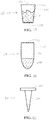
- FIG. 6A is side view of first tube 200.
- the first tube 200 can include a body 202 at least partially enclosing a cavity 204. Further, the first tube 200 can include an opening 206 at one end, and seal 208 at an opposite end. In some examples, the first tube 200 can comprise a generally square or flat end proximate the seal 208.
- FIG. 6B is a side view of second tube 210.
- the second tube 210 can include a body 212, cavity 214 formed in the body 212, and an opening 216 positioned at a first end of the cavity 214. In the non-limiting examples shown, the second tube 210 can include a closed end comprising a generally rounded or curved end.
- the first tube 200 can contain a buffer solution B in the cavity 204 of body 202. Further, in some examples, the second tube 210 can contain a lyophilized master mix LMM positioned in the cavity 214 of body 212.
- FIG. 6C is a side view of lid 220.
- the lid 220 can include a lid portion 222 and pipette tip 224.
- the pipette tip 224 is coupled to and extends from a first side of lid portion 222 of the lid 220.
- the lid 220 can be positioned in a tube (e.g., such as tubes 200, 210) so that pipette tip 224 can extend into the tube, and the lid portion 222 forms at least a partial seal with at least a portion of the tube.
- the first tube 200 and/or the second tube 210 and/or the pipette tip 224 can be configured to process a sample (e.g., such as a biological sample).
- a sample e.g., such as a biological sample.
- FIG. 7 is a flow chart showing the steps of preparing biological sample S for testing.
- FIG. 7 includes steps 230, 232,234, 236, and 238.
- the steps of preparing biological sample S for testing can include the order as shown.
- any of the steps 230, 232, 234, 236, 238 can proceed in a different order than shown.
- any of the steps 230, 232, 234, 236, 238 can be included, omitted, or repeated.
- FIGS. 8-10 illustrate views representing at least one or more of the process steps of FIG. 7 .
- FIG. 8 is a side view of the first tube 200 positioned in the second tube 210
- FIG. 9 is a side view of the first tube 200 positioned in the second tube 210 with lid 220 being placed in the first tube 200.
- FIG. 10 is a side view of the first tube 200 positioned in second tube 210 with lid 220 fully placed on the first tube 200.
- step 230 can include adding biological sample S to a first tube 200 that contains buffer solution B.
- buffer solution B can be placed in the first tube 200 prior to the collection of biological sample S.
- the buffer solution B in first tube 200 can vary depending on the type of biological sample S.
- the biological sample S can be pipetted into opening 206 of first tube 200 to mix with the buffer solution B in the cavity 204 to create a biological sample S and buffer solution B mixture (B+S).
- step 232 includes positioning a second end of the first tube 200 in the second tube 210, as seen in FIG. 8 .
- the second end of first tube 200 has smaller diameter than the diameter of the first end of second tube 210, thereby allowing the insertion of at least a portion of the first tube 200 into the cavity 214.
- the body 202 of first tube 200 include walls that slope based on a smaller diameter of the body 202 at the second end to a larger diameter of the body 202 at the first end.
- the first tube 200 can at least partially slide into the second tube 210 until the outer diameter of first tube 200 is about the diameter of the inner diameter of the first end of the second tube 210. In some examples, this can form at least a partial seal between the first tube 200 and the second tube 210.
- the second tube 210 contains lyophilized master mix LMM. In some examples, the lyophilized master mix LMM in second tube 110 can vary depending on what biological sample S is to be tested.
- step 234 can include positioning the pipette tip 224 of lid 220 in the first tube 200, as seen in FIG. 9 .
- step 236 can include puncturing the seal 208 on the first tube 200 with the pipette tip 224 of lid 220.
- the pipette tip 224 of lid 220 can be longer than the first tube 200, and thus in some examples, as the pipette tip 224 of lid 220 is positioned in first tube 200, the pipette tip 224 can contact the seal 208 of the first tube 200.
- the pipette tip 224 can puncture the seal 208 of the first tube 200 as pipette tip 224 is moved through the first tube 200 and into the second cavity 214.
- pipette tip 224 can be a sharp tip capable of puncturing seal 208 but without pipetting capabilities.
- the puncturing seal 208 can cause biological sample and buffer solution B+S to flow from first tube 200 into second tube 210.
- the biological sample and buffer solution B+S can then mix with lyophilized master mix LMM to form a final mixture FM that is suitable for testing.
- step 238 can include positioning the lid portion 222 of lid 220 on the first tube 200 to form at least a partial seal between the lid 220 and the first tube 200, as seen in FIG. 10 .
- the pipette tip 224 can extend through the first tube 200 and into the second tube 210 until the lid portion 222 of lid 220 comes into contact with first tube 200. In some examples, this can form a seal between the lid 220 and the first tube 200. Further, in some examples, the lid 220, first tube 200, and second tube 210 can then be placed in a device for testing.
- the first tube 200, second tube 210, and lid 220 can allow a user to prepare a crude biological sample S for testing in the field.
- the lid 220, first tube 200, and second tube 210 are advantageous, as they allow a user to prepare biological sample S for testing in the field using minimal instruments.
- the first tube 200 and the second tube 210 can have a buffer solution B and lyophilized master mix LMM added to them, and can then be taken into the field.
- a crude biological sample S can then be collected in the field and placed in the first tube 200, and mixed with buffer solution B.
- the first tube 200 can then be positioned in second tube 210 to form at least a partial seal between first tube 200 and second tube 210.
- the pipette tip 224 of lid 220 can then be positioned in first tube 200 and moved through first tube 200.
- the pipette tip 224 can contact with and puncture the seal 208 on first tube 200 as described earlier. In some examples, this can cause the field-sampled biological sample and buffer solution mixture B+S to flow into the second tube 210, where the biological sample and buffer solution mixture B+S can mix with the lyophilized master mix LMM.
- the steps as described can further process the biological sample S for testing by placing the Lid 220, first tube 200, and second tube 210 in a testing device.
- the first tube 200 and the second tube 210 can be used with alternative types of lid structures.
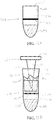
- FIG. 11A is a side view of the lid 220A
- FIG. 11 IB is a side view of the first tube 200 positioned in the second tube 210 with lid 220 A being placed in the first tube 200.
- the lid 220A can include a lid portion 222A, pipette tip 224A, and bulb portion 226A.
- the pipette tip 224A can be coupled to the first side of the lid portion 222A
- the bulb portion 226A can be coupled to a second side of the lid portion 222A.
- the bulb portion 226A can include a cavity that is coupled to a cavity of pipette tip 224A.
- this structure can enable the lid 220A to act as a pipette.
- a user can grasp and squeeze the bulb portion 226A, place the pipette tip 224A in a fluid, and release the bulb portion 226A to suck the fluid into the pipette tip 224A.
- the use of the lid 220 A with the first tube 200 and the second tube 210 can allow a user to use the lid 220A to pipette the biological sample S into the first tube 200 to mix with buffer solution B.
- the pipette tip 224 A of lid 220 A can then be used to puncture the seal 208 in the first tube 200 and lid portion 222A of lid 220A can seal against first tube 200, as described in reference to FIGS. 6A-10 above.
- the second tube 210 can include an integrated filter.
- FIG. 12A is a side view of a second tube 210A.
- FIG. 12B is a side view of the first tube 200 positioned in the second tube 21 OA with the lid 220 being placed in the first tube 200.
- the second tube 21 OA can include body 212A, cavity 214A formed by the body 212A, opening 216A, and filter 218 A positioned in the cavity 214A extending from one side of the body 212 A to an opposite side of the body 212A.
- the opening 216A can be positioned at a first end of the cavity 214A in the second tube 21 OA.
- the second tube 21 OA can contain lyophilized master mix LMM in the cavity 214A of the body 212A of the second tube 21 OA.
- the steps and processes described above in FIGS. 6 A-10 can be performed with the first tube 200 in combination with a second tube including an integrated filter. For example, as seen in FIG.
- the first tube 200 can be positioned above the filter 218A in the second tube 21 OA.
- a biological sample and reagent mixture B+S can flow from the first tube 200 through the filter 218 A into the second tube 21 OA.
- the filter 218 A can filter contamination or other unwanted or undesirable material in the biological sample and buffer solution mixture S+B.
- filtering contamination or other unwanted or undesirable material from the biological sample and reagent mixture B+S can improve the accuracy of testing of biological sample and reagent mixture B+S.
- FIG. 13 A is a cross-sectional view of a first tube 200A.
- the first tube 200A can include body 202A at least partially enclosing the cavity 204A, an opening 206A at one end of the cavity 204A, and a seal 208A at an opposite end of the cavity 204A, and flange 209A.
- the first tube 200A further contains flange 209A positioned around an outside diameter of body 202A.
- the flange 209A can be positioned between the first end and the second end of first tube 200A.
- the flange 209A can include a flat face on a first side and an angled face on a second side.
- FIG. 13B is a cross-sectional view of a second tube 210B.
- the second tube 210B can include body 212B, cavity 214B, opening 216B, and flange 219B.
- the first tube 200 A and second tube 210B can be used to process a sample using a lid such as the lid 220.
- FIG. 13C is a cross-sectional view of the first tube 200A positioned at least partially in the second tube 210B
- FIG. 13D is a cross-sectional view of first tube 200A positioned in second tube 210B with the lid 220 being placed in first tube 200 A.
- the first tube 200A can contain buffer solution B in cavity 204A of body 202A of first tube 200A, and when the first tube 200A is positioned in the second tube 21 OB, as seen in FIGS. 13C-13D , the flanges 209 A can engage the flanges 219B to prevent first tube 200 A from being pulled out of second tube 21 OB.
- the angled faces of flanges 209 A can slide against the angled faces of flange 219B.
- the faces of flanges 209A can slide at least partially past or over the angled faces of flange 219B.
- the flanges 209 A can couple with the inner surface of the second tube 210B, and/or at least a portion of the flange 219B.
- any conventional coupling mechanism can be used to couple the first tube 200A to the second tube 210B, and can be used to substantially retain the first tube 200A in the second tube 210B as shown in FIGS. 13C-13D .
- first tube 200A can be fully positioned in the second tube 210B, the flat face of the flange 209 A can sit against the flat face of flange 219B. In some examples, this engagement can prevent the first tube 200A from being removed from the second tube 210B, and can also prevent contamination from passing into second tube 210B.
- the pipette tip 224 of the lid 220 can then be pushed through first tube 200A to puncture seal 208A on first tube 200A, and the lid 220 can at least partially seal against the first tube 200A.
- the various examples of first tube 200, second tube 210, and lid 220 described in FIGS. 6-13D above can be integrated with one another in any way.
- FIG. 14 is a plan view of multi-chamber inline sample processing device 300.
- the sample processing device 300 can include three inline chambers, which together define an inline flow path of a material through the sample processing device 300.
- the sample processing device 300 can include cap 302, pulverization chamber 304, first separation element 306, extraction chamber 308, second separation element 310, and dilution chamber 312.
- the size and volume of each chamber of device 300 can be scaled to match the quantity of material to be processed. In this way, each of chambers, 304, 308, and 312 can be sized according to the quantity of material to be processed.
- chamber 304 can be sized smaller to process single seeds or leaf punches or sized larger to accommodate a collection of seeds or other material that form a representative sample of a large collection of material to be analyzed.
- each of the chambers 304, 308, 312, cap 302, and separation elements 306, 310 of device 300 can be sized independently based on the application and quantity of materials needed.
- the sample processing device 300 can be formed as a single piece. In some examples, the sample processing device 300 can be formed using a mold and first separation element 306 and second separation element 310 can be press fit into the sample processing device 300. In other examples, each of the chambers 304, 308, and 312 can be separate modules that when coupled together form the sample processing device 300. Additionally, in some examples, each of the chambers 304, 308, and 312 can have other shapes other than the frustoconical shapes depicted in FIG. 14 . As an example, each chamber 304, 308, or 312 can have a cylindrical shape.
- the cap 302 can be coupled to the pulverization chamber 304 at an upstream end of pulverization chamber 304 with respect to a direction F of flow. Terms such as upstream and downstream as used in this description refer to relative positions along the direction of flow F.
- the first separation element 306 can be coupled both to a downstream end of pulverization chamber 304 and to an upstream end of the extraction chamber 308.
- the second separation element 310 can be coupled both to a downstream end of extraction chamber 308 and to an upstream end of dilution chamber 312.
- a biological sample such as a plant tissue, seed, or a combination of material from different sources can be pulverized or mechanically distressed in pulverization chamber 304.
- a portion of the pulverized tissue can be passed through the first separation element 306 and into the extraction chamber 308.
- nucleic acids can be extracted from the plant tissue within the extraction chamber 308.
- the extracted nucleic acids can then pass through the second separation element 310 and into the dilution chamber 312.
- the extracted nucleic acids in the dilution chamber 312, can be neutralized with a neutralization buffer and diluted with water or a dilution buffer. The specific structure and operation of each chamber is described in further detail below.
- FIG. 15A is a plan view of sample processing device 300 showing tissue sample 314 inserted in pulverization chamber 304.
- the tissue sample 314 can be any type or mixture of plant tissue, including, but not limited to, seed, leaf, husk or bark, or any other single type of plant tissue(s) or mixture of plant tissue types.
- the pulverization chamber 304 can include an upstream end 316, a downstream end 318, a side wall 320, an upstream opening 322, and a downstream opening 324.
- the pulverization chamber 304 can be defined by an upstream end 316 and a downstream end 318, which are joined by side wall 320.
- the upstream end 316 can define an upstream opening 322, which has a generally circular shape and is sized to permit tissue sample 314 to be inserted into the pulverization chamber 304, where pulverization of tissue sample 314 can help to break down the components of tissue sample 314, such as cell walls, in order to access nucleic acids.
- the pulverization chamber 304 can include an overall frustoconical shape, which tapers towards the first separation element 306.
- the frustoconical shape of pulverization chamber 304 can help drive materials towards the extraction chamber 308 (not shown in FIG. 15A ).
- the downstream end 318 can define a downstream opening 324, which in some examples, can permit a flow of materials from pulverization chamber 304 to enter the extraction chamber 308.
- FIG. 15B is a plan view of the sample processing device 300 showing pulverization chamber 304 with cap 302 coupled and showing the tissue sample 314 in a pulverized state.
- the cap 302 can cover an upstream opening 322.
- the cap 302 can include ports 326, and grinder 328.
- the cap 302 can be a snap-fit or twist-fit on to the upstream end 316.
- a tissue sample 314 can be loaded into the pulverization chamber 304 and pulverized (e.g., the tissue sample 314 can be broken in smaller pieces.)
- the tissue sample 314 can be pulverized in different ways.
- the side wall 320 of pulverization chamber 304 can be formed from a flexible material that can be compressed by mechanical means (e.g., such as a handheld or machine operated pliers or other constriction.) As the pulverization chamber 304 is compressed, the tissue sample 314 can be crushed into smaller pieces.
- the interior of the pulverization chamber 304 can be configured to include an abrasive or corrugated surface, which can help to break down tissue sample 314.
- conventional pliers, or other mechanical means can also be inserted into the pulverization chamber 304 to directly pulverize the tissue sample 314.
- an abrasive corrugated surface can be inserted into chamber 304, and a friction between the abrasive surface and the grinder 328 of cap 302 can be used to break tissue sample 314 into smaller pieces.
- the grinder 328 can then be spun to break down tissue sample 314.
- the tissue sample 314 can be dehydrated or flash frozen prior to being inserted into pulverization chamber 304 to make the tissue sample 314 more brittle and easier to pulverize.
- FIG. 16 is a plan view of sample processing device 300 showing extraction chamber 308 with tissue sample 314 and extraction buffer 330 disposed therein.
- the extraction chamber 308 can include an upstream end 332, a downstream end 334, a side wall 336, an upstream opening 338, and a downstream opening 340, and a first separation element 306.
- the extraction chamber 308 can be defined by the upstream end 332 and the downstream end 334, which are joined by side wall 336.
- the upstream end 332 can comprise a frustoconical shape which tapers away from the downstream end 334.
- the upstream end 332 can define an upstream opening 338, which permits flow from the pulverization chamber 304 to enter extraction chamber 308.
- the frustoconical shape of the upstream end 332 can help to disperse components within extraction chamber 308 upon entry.
- the downstream end 334 can include a frustoconical shape which tapers away from upstream end 332.
- the downstream end 334 defines a downstream opening 340, which permits flow from extraction chamber 308 to enter dilution chamber 312 (not shown).
- the frustoconical shape of downstream end 334 can help drive components towards dilution chamber 312.
- the tissue sample 314 can be pulverized as described above with respect to FIGS. 15A and 15B .
- an extraction buffer 330 can be supplied to the pulverization chamber 330 through one of ports 326, and the other port 326 can act as a pressure relief vent.
- the extraction buffer 330 can be any one of many conventional buffers or mixtures of conventional buffers, including, but not limited to, Sodium Hydroxide (NaOH) based buffers.
- a suitable buffer can be formed from NaOH and Sodium Dodecyl (luryl) Sulfate (SDS). SDS is a surfactant that can help to solubilize a cell membrane, while NaOH can help to break down the cell wall and disrupts hydrogen bonding between DNA bases (and thus converting the double-stranded DNA into single-stranded DNA.)
- air can be supplied through both of ports 326, shown in order to force material though the first separation element 306 and into extraction chamber 308.
- a vacuum line can be coupled to one of ports 350 shown in FIG. 17A to pull material through first separation element 306 instead of using air pressure supplied through ports 326.
- air pressure can be supplied through ports 326 while a vacuum is applied through ports 350.
- centrifuge action can be used to push material through the first separation element 306 instead of air pressure or vacuum.
- the first separation element 306 can be disposed between the downstream end 318 of the pulverization chamber 304 and the upstream end 332 of extraction chamber 308.
- the first separation element 306 can be configured to filter the flow of materials between the pulverization chamber 304 and extraction chamber 308.
- the first separation element 306 can be a conventional filter or a screen.
- the filter or screen can be designed to block some of the larger pulverized tissue samples 314 but can allow individual cells, organelles, etc. to pass through first separation element 306.
- first separation element 306 can be a bursting membrane configured to burst when the pressure inside pulverization chamber 304 (generated by air passed through ports 326) exceeds a threshold value. When the membrane bursts, all the contents of pulverization chamber 304 can be free to enter extraction chamber 308.
- a portion of the pulverized tissue sample 314 and extraction buffer 330 can enter the extraction chamber 308 after passing through the first separation element 306.
- the extraction buffer 330 can function as stated above to extract nucleic acids such as DNA and/or other components from the pulverized tissue sample 314.
- the tissue 314 and extraction buffer 330 in extraction chamber 308 can be heated. The exact temperature to which the tissue 314 and extraction buffer 330 in extraction chamber 308 is heated can depend on which extraction buffer 330 is used. Typically, tissue 314 and extraction buffer 330 in extraction chamber 308 can be heated to anywhere from about 65 degrees Celsius (about 149 degrees Fahrenheit) to about 80 degrees Celsius (about 176 degrees Fahrenheit).
- heating can be applied either locally to the extraction chamber 308, or generally to the entire device 300.
- the tissue 314 and the extraction buffer 330 in extraction chamber 308 can be cooled to room temperature.
- the extraction chamber 308 can include some pulverized tissue sample 314 and extracted nucleic acids 352.
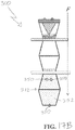
- FIG. 17A is a plan view of sample processing device 300 showing dilution chamber 312.
- the dilution chamber 312 can include an upstream end 342, downstream end 344, side wall 346, upstream opening 348, and ports 350.
- FIG. 17A also shows second separation element 310, and extracted nucleic acids 352 and neutralization buffer 354.
- the dilution chamber 312 can be defined by the upstream end 342 and downstream end 344, which are joined by side wall 346.
- the upstream end 342 can include a frustoconical shape which tapers away from downstream end 344.
- the upstream end 342 defines upstream opening 348, which permits flow from extraction chamber 308 to enter dilution chamber 312.
- the frustoconical shape of upstream end 342 can help to disperse components within dilution chamber 312 upon entry.
- the downstream end 344 has a frustoconical shape which tapers away from upstream end 342.
- the dilution chamber 312 can include ports 350. As illustrated, in some examples, the two of ports 350 can be located proximate to upstream end 342, and one of ports 350 can be located proximate to the downstream end 344. In some examples, the frustoconical shape of downstream end 344 can help drive components towards port 350.
- FIG. 17A shows extracted nucleic acid 352 in dilution chamber 312 and pulverized tissue 314 in extraction chamber 308.
- air can be forced through ports 326 causing extracted nucleic acid 352 to pass through the second separation element 310.
- the second separation element 310 can be disposed between the downstream end 334 of extraction chamber 308 and the upstream end 342 of dilution chamber 312.
- the second separation element 310 can be a filter or screen that is configured to filter smaller particles than first separation element 306.
- the second separation element 310 can be sized to not allow pulverized tissue sample 314 to pass through.
- extracted nucleic acid 352 and pulverized tissue sample 314 can be separated using the process as described.
- a vacuum line can be coupled to one of ports 350 to pull extracted nucleic acid 352 through second separation element 310 instead of using air pressure supplied through ports 326.
- air pressure can be supplied through ports 326 while a vacuum is applied through ports 350.
- a centrifuge action can be used to push extracted nucleic acid 352 through second separation element 310 instead of air pressure or vacuum.
- neutralizing buffer 354 can be supplied through one of the ports 350.
- the neutralizing buffer 354 can serve to bring the pH of the solution in dilution chamber 312 to a suitable level for storing isolated nucleic acid 352.
- suitable neutralizing buffers including, but not limited to Tris-Hydrochloride (TRIS-HCl).
- FIG. 17B is a plan view of sample processing device 300 showing diluted isolated nucleic acid sample 352.
- the solution can be diluted using water or a buffer.
- buffers for dilution of nucleic acids.
- An example of a suitable dilution buffer is Tris-EDTA (TE) buffer.
- TE Tris-EDTA
- the dilution chamber 312 can be removed from sample processing device 300 directly, and isolated nucleic acid 352 can be stored therein.
- the isolated nucleic acid 352 can also be dispensed into a vial through port 350.
- isolated nucleic acid 352 can be amplified using polymerase chain reaction (PCR) and analyzed using fluorescence scanning techniques.
- isolated nucleic acid 352 can also be aspirated through port 350 directly to a sample vial or an inline amplification device that can amplify the nucleic acids and analyze them using fluorescence scanning techniques.
- FIG. 18 is a flow diagram showing a method 356 for performing an inline extraction and amplification of a nucleic acid.
- the method 356 can include an insertion step 358, and/or a pulverization step 360, and/or an injection step 362, and/or a filtration step 364, an/or an extraction step 366, an/or a filtration step 368, and/or a neutralization step 370, and/or a dilution step 372.
- any of the steps 358, 360, 362, 364, 366, 368, 370, 372 can proceed in a different order than shown.
- any of the steps 358, 360, 362, 364, 366, 368, 370, 372 can be included, omitted, or repeated.
- a tissue sample 314 can be loaded into the pulverization chamber 304 of the multi-module inline sample processing device 300.
- the tissue sample 314 can be pulverized into a powder.
- an extraction buffer 330 can be added to the pulverization chamber 304.
- the filtration step 364 can follow the injection step 362.
- the solution of extraction buffer 330 and the pulverized tissue sample 314 can be forced through the first separation element 306 and into extraction chamber 308 of sample processing device 300.
- the solution of extraction buffer 330 and the pulverized tissue sample 314 can be heated and then cooled to room temperature.
- the filtration step 368 follows the extraction step 366.
- extracted nucleic acid 352 can be filtered through the second separation element 310 and into the dilution chamber 312.
- the pulverized tissue sample 314 can remain in the extraction chamber 308.
- a neutralization buffer 354 can be added to dilution chamber 312 to neutralize isolated nucleic acid 352.
- water or a dilution buffer can be added to the dilution chamber 312.
- isolated nucleic acid 352 can be stored, and/or aspirated to an inline device to perform nucleic acid amplification, and/or or dispensed into a sample vial that can be inserted into an amplification device.
- FIG. 19 is a side view of sample processing device 400
- FIG. 20 is a cross-sectional view of the sample processing device 400 along line A-A in FIG. 19
- FIG. 21A is a cross-sectional view of sample processing device 400A, one example of sample processing device 400 shown in FIGS. 1 and 2
- FIG. 21B is a cross-sectional view of sample processing device 400B, another example of sample processing device 400 shown in FIGS. 1 and 2 .
- the sample processing devices 400, 400A, 400B are advantageous because they reduce the risk of contamination when pulverizing and denaturing a sample to prepare the sample for testing. Devices 400, 400A, 400B can eliminate the need to perform pulverization in one vessel and transfer the pulverized sample into another vessel for denaturing, thus reducing opportunities for contamination of the sample.
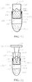
- the sample processing devices 400, 400A, and 400B can be disposable tubes.
- the sample processing devices 400, 400A, and 400B can include a cylindrical portion 402 coupled or integrated with a tapered portion 404, cap 406, cap 408, ribs 410, and ring 412.
- the cylindrical portion 402 and tapered portion 404 can be at least partially hollow.
- the cap 406 can at least partially cover the end of cylindrical portion 402, and the cap 408 can at least partially cover the end of tapered portion 404.
- the ribs 410 and ring 412 can be coupled to the cylindrical portion 402 of the sample processing device 400.
- the ribs 410 can extend along cylindrical portion 402. Some examples include a ring 412 that is located at the end of ribs 410 proximate or adjacent to where the cylindrical portion 402 meets the tapered portion 404.
- sample processing devices 400A and 400B can be similar to sample processing device 400, except sample processing device 400A can include a pulverizer 416A, and sample processing device 400B can include a pulverizer 416B.
- the pulverizer 416A can be cylindrically shaped.
- the pulverizer 416B can be spherically shaped. The following description references sample processing device 400A as shown in FIG. 21A , but the description can apply to both sample processing device 400A and sample processing device 400B.
- the pulverizer 416A can be contained within cylindrical portion 402.
- the ring 412 can prevent the pulverizer 416A from sliding into the tapered portion 404 of the sample processing device 400 A.
- the pulverizer 416A can be any shape that can be contained by ribs 410 and ring 412 within cylindrical portion 402 of sample processing device 400A.
- the ribs 412 can prevent the pulverizer 416A from touching the sides of sample processing device 400, and can allow the pulverizer 416A to slide within cylindrical portion 402.
- the pulverizer 416A can be any non-reactive material such as glass, ceramic, stainless steel, or any non-reactive polymer.
- the sample processing device 400A can enable a crude sample to be both pulverized and denatured in the same vessel.
- the cap 406 in order to pulverize and denature a sample, the cap 406 can be removed from the end of cylindrical portion 402, and pulverizer 416A can be placed within the cylindrical portion 402.
- the crude sample can be placed into the cylindrical portion 402.
- the crude sample can be one or more pieces of corn, one or more seed or seed portions, one or more leaves or leave portions, combinations thereof, or any other solid biological sample.
- the cap 406 can be placed back on the end of cylindrical portion 402.
- the sample processing device 400 A can be manufactured with pulverizer 416A already contained within cylindrical portion 402, and the crude sample can be added into either the cylindrical portion 402 through the cap 406 or the tapered portion 404 through the cap 408.
- the sample processing device 400A can be placed into an instrument, such as a shaker, with the cap 406 facing down.
- the instrument can shake the sample processing device 400A such that the pulverizer 416A can move against the ribs 410 and slide within cylindrical portion 402 to macerate the crude sample.
- the sample processing device 400A can be removed from the instrument.
- the cap 408 can then be removed from the tapered portion 404, and a denaturing agent, such as sodium hydroxide, can be added into the tapered portion 404.
- the tapered shape of the tapered portion 404 and ring 412 can prevent the pulverizer 416A from sliding into the tapered portion 404 when the denaturing agent is added. In some examples, this can reduce the risk of contamination by ensuring that pulverizer 416A is contained within cylindrical portion 402, and is prevented from sliding out of the sample processing device 400A. In some examples, after the denaturing agent has been added, the cap 408 can be placed back on the tapered portion 404.
- the sample processing device 400A can be placed back into the instrument with the cap 408 facing down.
- the instrument can shake the sample processing device 400A such that the denaturing agent at least partially denatures the DNA within at least a portion of the pulverized sample.
- the gaps between the ribs 410 can allow the denaturing agent to flow within the cylindrical portion 402 in addition to the tapered portion 404 in order to denature the entire pulverized sample.
- At least a portion of the denatured sample can be transferred into a separate vessel for testing, or the portion of the denatured sample can be tested in sample processing device 400A.
- the cap 408 can be opened in order to transfer the sample.
- the tapered portion 404 and ring 412 can prevent the pulverizer 416A or pulverizer 416B from sliding out of sample processing device 400A when the denatured sample is being transferred.
- FIG. 22 is a perspective view of sample processing device 500 in accordance with one embodiment of the invention.
- the sample processing device 500 includes tube 502 and cap 504.
- the tube 502 includes basket 506 with grid 508 and tabs 510.
- the tube 502 also includes a barcode 512, and is filled with lysis buffer 514 that can lyse cells within a macerated sample prepared within the device 500 in order to expose the DNA within the cells for further testing.
- the basket 506 is a removable basket that sits in tube 502 with tabs 510 hanging over the edge of the tube 502.
- the cap 504 includes a punch edge 516 and fingers 518.
- the sample processing device 500 is used to take a sample of a crude biological material, such as a leaf, seed, or clip from an ear of corn, and force the sample through the grid 508 of the basket 506 to macerate the sample.
- the macerated sample is combined with the lysis buffer 514 to extract at least some DNA from the sample for further testing.
- the cap 504 is coupled to the tube 502 to at least partially seal the tube 502.
- the cap 504 is a snap top cap.
- the punch edge 516 can punch a sample out of the crude biological sample and into the basket 506.
- the punch edge 516 is a ring-shaped sharp edge suitable for cutting a crude biological sample.
- the fingers 518 force the sample through the grid 508 of basket 506 to macerate the sample. The macerated sample can then fall into lysis buffer 514.
- the grid 508 and fingers 518 may be made of a polymer, a metal (e.g., such as aluminum or stainless steel), a composite material, a ceramic or glass, or combinations thereof.
- the closing cap 504 may cause the tabs 510 to break off of basket 506 such that basket 506 with any macerated sample remaining on the grid 508 can fall into the lysis buffer 514.
- the closing cap 504 may cause the tabs 510 to break off the basket 506 so that the cap 504 can be completely sealed on the tube 502, but the basket 506 does not fall into the lysis buffer 514. This can enable the macerated sample to be kept separate from lysis buffer 514 before combining the macerated sample and lysis buffer 514.
- the tabs 510 may ensure that the sample processing device 500 can be used only once, thus avoiding potential combining of biological samples when collecting multiple samples into multiple sample processing devices.
- sample processing device 500 can be used without lysis buffer 514.
- sample processing device 500 can be used to punch and macerate a sample and store the macerated sample for future testing.
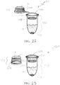
- FIG. 23 is a perspective view of sample processing device 520, another embodiment of sample processing device 500 in FIG. 22 .
- the sample processing device 520 includes a tube 522 with internal threads 523 and cap 524 with external threads 525.
- the cap 524 includes punch edge 536 and teeth 538.
- the tube 522 includes basket 526 with grid 528 and tabs 530.
- the basket 526 is a removable basket that sits in tube 522 with tabs 530 hanging over the edge of tube 522.
- the tube 522 also includes barcode 532, and is filled with lysis buffer 534.
- the sample processing device 520 functions in substantially the same manner as sample processing device 500 in FIG. 22 , except cap 524 includes teeth 538 instead of fingers 518. Further, cap 524 screws into the tube 522 instead of snapping onto tube 522; external threads 525 of cap 524 fit into internal threads 523 of tube 522.
- crude biological material is placed on top of tube 522. As cap 524 is threaded into tube 522, punch edge 536 punches a sample out of the crude biological sample into basket 526. Further, as cap 524 is threaded into tube 522, teeth 518 grind the sample through grid 528 of basket 526 to macerate the sample.
- the teeth 518 comprise a textured surface that grinds the sample through grid 528 which then falls into the lysis buffer 534.
- Closing cap 524 may cause the tabs 530 to break off of the basket 526 so that basket 526 with any macerated sample remaining on grid 528 falls into lysis buffer 534.
- FIG. 24 is a perspective view of sample processing device 540, another embodiment of sample processing device 500 in FIG. 22 .
- the sample processing device 540 includes tube 542 and cap 544.
- the tube 542 includes basket 546 with grid 548 and tabs 550.
- the basket 546 is a removable basket that sits in tube 542 with tabs 550 hanging over the edge of tube 542.
- the tube 542 also includes barcode 552, sodium hydroxide pouch 554, and permeable layer 555.
- the cap 544 includes a punch edge 556 and fingers 558 with piercers 559.
- the sample processing device 540 functions in substantially the same manner as sample processing device 500 in FIG. 22 , except tube 542 includes sodium hydroxide pouch 554 and permeable layer 555 instead of lysis buffer 514, and fingers 558 include piercers 559.
- crude biological material is placed on top of tube 542.
- the cap 544 is used to at least partially seal the tube 542.
- the punch edge 556 can punch a sample out of the crude biological sample into basket 546.
- the fingers 558 force the sample through grid 548 of basket 546 to macerate the sample, and piercers 559 puncture the sodium hydroxide pouch 554.
- cap 544 includes four piercers on fingers 558.
- cap 544 can include a single piercer 559 or multiple piercers 559.
- the piercers 559 comprise sharp tips capable of puncturing the sodium hydroxide pouch 554.
- the permeable layer 555 may be a metal or plastic screen. Closing cap 544 may cause the tabs 550 to break off of basket 546 with any macerated sample remaining on grid 548 falls onto permeable layer 555.
- the permeable layer 555 allows the sodium hydroxide and macerated sample to pass through into the bottom of tube 542, but prevents the basket 546 from passing into the bottom of tube 542.
- the sodium hydroxide denatures DNA within the macerated sample in order to expose the DNA within the cells for further testing.
- FIG. 25 is a perspective view of sample processing device 560, another embodiment of sample processing device 500 in FIG. 22 .
- the sample processing device 560 includes tube 562 with internal threads 563 and cap 564 with external threads 565.
- the tube 562 includes basket 566 with grid 568 and tabs 570.
- the basket 566 is a removable basket that sits in the tube 562 with tabs 570 hanging over the edge of tube 562.
- the tube 562 also includes barcode 572, sodium hydroxide pouch 574, and permeable layer 575.
- the cap 564 includes punch edge 576, teeth 578, and piercer 579.
- the sample processing device 560 functions in substantially the same manner as sample processing device 540 in FIG. 24 , except cap 564 includes teeth 578 instead of fingers 558. Additionally, the cap 564 screws into the tube 562 instead of snapping onto tube 562; external threads 565 of cap 564 fit into internal threads 563 of tube 562.
- crude biological material is placed on top of tube 562. As cap 564 is threaded into the tube 562, the punch edge 576 punches a sample out of the crude biological sample into basket 566.
- the teeth 578 grind the sample through grid 568 of basket 566 to macerate the sample, and piercer 579 punctures the sodium hydroxide pouch 574.
- the piercer 579 comprises a needle-shaped projection.
- sodium hydroxide pouch 574 Once the sodium hydroxide pouch 574 is pierced, sodium hydroxide and macerated sample pass through permeable layer 575 into the bottom of tube 562. Closing the cap 564 may cause the tabs 570 to break off of basket 566 with any macerated sample remaining on the grid 568 falling onto the permeable layer 575.
- the permeable layer 575 allows the sodium hydroxide and macerated sample to pass through into the bottom of the tube 562 but prevents the basket 566 from passing into the bottom of tube 562.
- FIG. 26 is a perspective view of sample processing device 580, another embodiment of sample processing device 500 in FIG. 22 .
- the sample processing device 580 includes tube 582 and cap 584.
- the tube 582 includes basket 586 with grid 588 and tabs 590.
- the basket 586 is a removable basket that sits in tube 582 with tabs 590 hanging over the edge of tube 582.
- the tube 582 also includes barcode 592.
- the cap 584 includes septum 593, sodium hydroxide pouch 594, permeable layer 595, punch edge 596, and fingers 558.
- Sample processing device 580 functions in substantially the same manner as sample processing device 540 in FIG. 24 , except cap 584 includes sodium hydroxide pouch 594 and septum 595, and the tube 582 does not include a sample processing liquid.
- crude biological material is placed on top of the tube 582, and the cap 584 is used to seal the tube 582.
- the punch edge 596 punches a sample out of the crude biological sample and into the basket 586.
- the fingers 598 force the sample through the grid 588 of basket 586 to macerate the sample. Closing the cap 584 may cause the tabs 590 to break off of the basket 586 so that the basket 586 with any macerated sample remaining on the grid 588 falls into the bottom of tube 582.
- a piercing device such as a needle, can be inserted into the septum 593 to pierce the sodium hydroxide pouch 594.
- the septum 593 may be a resealable septum.
- sodium hydroxide pouch 554 is pierced, sodium hydroxide passes through the permeable layer 595 and into the bottom of tube 582.
- the permeable layer 595 may be a metal or plastic screen.
- the cap 584 is made of a compressible material such that sodium hydroxide pouch 594 can be popped by applying pressure to cap 584.
- FIG. 27 is a perspective view of sample processing device 600, another embodiment of sample processing device 500 in FIG. 22 .
- the sample processing device 600 includes tube 602 with internal threads 603 and cap 604 with external threads 605.
- the tube 602 includes basket 606 with grid 608 and tabs 610.
- the basket 606 is a removable basket that sits in tube 602 with tabs 610 hanging over the edge of tube 602.
- the tube 602 also includes barcode 612
- the cap 604 includes septum 613, sodium hydroxide pouch 614, permeable layer 615, punch edge 616, and teeth 618.
- the sample processing device 600 functions in substantially the same manner as sample processing device 580 in FIG. 26 , except cap 604 includes teeth 618 instead of fingers 598. Additionally, the cap 604 screws into the tube 602 instead of snapping onto the tube 602; external threads 605 of cap 604 fit into internal threads 603 of tube 602.
- crude biological material is placed on top of tube 602.
- punch edge 616 punches a sample out of the crude biological sample into basket 606.
- teeth 618 grind the sample through grid 618 of basket 606 to macerate the sample.
- Closing cap 604 may cause tabs 610 to break off of basket 606 such that basket 606 with any macerated sample remaining on grid 608 falls into the bottom of tube 602.
- a piercing device such as a needle, can be inserted into septum 613 to pierce sodium hydroxide pouch 614. Once the sodium hydroxide pouch 614 is pierced, sodium hydroxide passes through permeable layer 615 into the bottom of tube 602.
- the cap 604 is made of a compressible material and the sodium hydroxide pouch 614 can be popped by applying pressure to cap 604.
Landscapes
- Health & Medical Sciences (AREA)
- Chemical & Material Sciences (AREA)
- Life Sciences & Earth Sciences (AREA)
- Clinical Laboratory Science (AREA)
- Chemical Kinetics & Catalysis (AREA)
- General Health & Medical Sciences (AREA)
- Engineering & Computer Science (AREA)
- Analytical Chemistry (AREA)
- Wood Science & Technology (AREA)
- Organic Chemistry (AREA)
- Bioinformatics & Cheminformatics (AREA)
- Zoology (AREA)
- Hematology (AREA)
- Biomedical Technology (AREA)
- Genetics & Genomics (AREA)
- Biotechnology (AREA)
- General Engineering & Computer Science (AREA)
- Biochemistry (AREA)
- Microbiology (AREA)
- Molecular Biology (AREA)
- Sustainable Development (AREA)
- Crystallography & Structural Chemistry (AREA)
- Physics & Mathematics (AREA)
- Biophysics (AREA)
- Plant Pathology (AREA)
- Sampling And Sample Adjustment (AREA)
- Apparatus Associated With Microorganisms And Enzymes (AREA)
Description
- The processing of raw biological samples for extraction of DNA for genetic profiling usually requires multiple vessels that are used through a plurality of processing steps. Typically, separate vessels are used for one or more different biochemical analysis steps, including taking the sample, disrupting the sample with chemical or mechanical means, extracting DNA from the sample, and analyzing the sample. Not only is the use of multiple vessels time-consuming and costly, the introduction of multiple surfaces and transfer of samples from one vessel to another can increase the risk of contamination that can introduce errors during the downstream sample analysis step. Accordingly, there is a need to integrate and miniaturize various sample processing steps into a unitary or modular device, to significantly reduce or eliminate the need to transfer biological samples between multiple separate vessels. A modular design can increase the efficiency of extracting nucleic acids from tissue samples, and increase efficiency by largely eliminating the need to transfer reactants between separate reaction vessels to perform each step of the extraction process. Furthermore, integration of the device with external automation equipment modular designs can allow the extraction process to be performed with only one action from the user, thereby enabling the process to be fully automated after the user initiates the extraction process.
-
US2003/134432A1 describes a system for producing a library of oligomer comprising at least two monomers in a positionally determined array comprise a plurality of synthesis supports, a first plurality of support carriers wherein each carrier has a uniform array of distinct support holding positions for the synthesis supports; means for contacting each array of synthesis supports with a different monomer to provide a first chemical transformation of the synthesis supports; a second plurality of support carriers wherein each carrier has a uniform array of distinct support holding positions for receiving the chemically transformed synthesis supports contained in the first plurality of support carriers; transfer apparatus for transferring a selected row or column of synthesis supports from each of the first plurality of carriers to each of the second plurality of carriers to enable the supports in the second to undergo at least a second chemical transformation; and whereby each support position in each carrier identifies the chemical compound thereon. -
WO2016/036464A1 describes tissue dissociators configured to disrupt a biological tissue sample. Aspects of the tissue dissociators may include a housing having a distal end and a proximal end, a cutting blade positioned at the distal end of the housing and a tissue actuator configured to be displaced along a longitudinal axis within the housing. Also described are methods of using the tissue dissociators, as well as kits including the tissue dissociators. -
US2007/014690A1 describes devices and methods for homogenization, processing, detection, and analysis of biological samples such as insects, fungi, bacteria, and plant and animal tissues. Multiple chambers in these devices permit different processing functions to be carried out at each stage, such that the resulting homogenized product can be further processed, purified, analyzed, and/or biomolecules such as metabolites, proteins and nucleic acids, or pharmaceutical products can be detected. The device can be used in a hydrostatic pressure apparatus, in which different activities, i.e. incubations, addition or renewal of reagent, and generation and detection of signal can be carried out in the appropriate chamber. The method improves the preservation of biomolecules from chemical and enzymatic degradation relative to conventional means. Additionally, this method enables automated sample preparation and analytical processes. - The present invention comprises a sample processing device and method as defined in the claims.
- There is described herein, a filter kit comprising a center portion, and a first connection portion coupled to a first side of the center portion, where the first connection portion is coupled to a first tube containing a buffer solution. Further, a second connection portion is coupled to a second side of the center portion, where the second connection portion is coupled to a second tube containing a lyophilized master mix. Further, the filter cap includes a first filter at least partially located in the first connection portion, and a second filter at least partially located in the second connection portion. In some further examples, the filter cap comprises a third filter at least partially located in the center portion of the filter cap.
- There is also described herein, a tube kit comprising a first tube containing a buffer solution, and a second tube containing a lyophilized master mix. The kit also includes a filter cap comprising a center portion, a first connection portion coupled to a first side of the center portion, and a second connection portion coupled to a second side of the center portion. Further, the kit also includes a first filter at least partially located in the first connection portion, and a second filter at least partially located in the second connection portion.
- In some examples, the first connection portion of the filter cap is configured to be positioned in a cavity in the first tube to form at least a partial mechanical seal with the first tube. In some further examples, the second connection portion of the filter cap is configured to be positioned in a cavity in the second tube to form at least a partial mechanical seal with the second tube.
- Some examples include a first adhesive on the first side of the center portion of the filter cap around the first connection portion, where the first adhesive is configured to form a seal between the filter cap and the first tube. Further, a second adhesive on the second side of the center portion of the filter cap around the second connection portion is configured to form a seal between the filter cap and the second tube.
- There is also described herein, a method comprising placing a biological sample in a first tube that is preloaded with a buffer solution, where a biological sample and buffer solution mixture is formed. Further, the method includes positioning a filter cap in the first tube, positioning a second tube on the filter cap, flipping the first tube, the filter cap, and the second cap, and filtering the biological sample and buffer solution mixture with the filter cap as it flows from the first tube to the second tube. Some further examples include positioning the filter cap in the first tube that includes positioning a first connection portion of the filter cap in the first tube. Some other examples include positioning a second tube on the filter cap that includes positioning a second tube on a second connection portion of the filter cap.
- There is also described herein, a tube kit comprising a first tube containing a buffer solution, where there is an opening at a first end of the first tube and a seal across a second end of the first tube. Further, the tube kit comprises a second tube containing a lyophilized master mix, and a lid with a tip coupled to the lid, where the second end of the first tube is configured to form a seal with the first end of the second tube, and where the tip coupled to the lid is configured to puncture the seal on the second end of the first tube as the lid is placed on the first tube.
- In some examples, the first tube sits in the second tube. In some further examples, the first tube clips onto the second tube. In other examples, the lid has a bulb top. In some further examples, the second tube includes a filter.
- There is also described herein, a method comprising adding a biological sample to a first tube containing a buffer solution, where the biological sample is added through an opening at a first end of the first tube, and positioning a second end of the first tube in a second tube, puncturing a seal on the second end of the first tube with a tip coupled to a lid, and positioning the lid on the first tube to form a seal between the lid and the first tube.
- There is also described herein, an inline sample processing device comprising a first chamber configured to receive a tissue sample and a nucleic acid extraction reagent, where the first chamber is configured to permit the tissue sample to be pulverized. Further, the method includes a second chamber in flow communication with the first chamber that is configured to receive the extraction reagent and a portion of the pulverized tissue sample. Further, the device includes a first separation element disposed between the first chamber and the second chamber and configured to permit a portion of the pulverized tissue sample and the extraction reagent to flow from the first chamber to the second chamber. Further, a third chamber is in flow communication with the second chamber, and has a plurality of ports configured to allow a reagent to be delivered to the third chamber, and a second separation element is disposed between the second chamber and the third chamber and is configured to substantially prevent the pulverized tissue from entering the third chamber.
- There is also described herein, a sample processing device for pulverization and denaturation comprising a hollow cylindrical portion, a hollow tapered portion, a first cap for covering an end of the cylindrical portion, and a second cap for covering an end of the tapered portion. Further, the device can include a plurality of ribs extending along the cylindrical portion, a ring at an end of the plurality of ribs where the cylindrical portion meets the tapered portion, and a pulverizer contained within the cylindrical portion between the ring and the first cap.
- In some examples, the pulverizer is cylindrical or spherical. In some further examples, the pulverizer is glass, ceramic, stainless steel, or a non-reactive polymer. In some other examples, the plurality of ribs prevents the pulverizer from touching sides of the sample processing device and allows the pulverizer to slide within the cylindrical portion. In some further examples, the ring prevents the pulverizer from entering the tapered portion of the sample processing device.
- There is also described herein, a method for pulverizing and denaturing a crude sample comprising placing a pulverizer in a sample processing device. The device can comprise a cylindrical portion, a tapered portion, and a plurality of ribs extending along the cylindrical portion, and a ring at an end of the plurality of ribs where the cylindrical portion meets the tapered portion. The method can include placing the crude sample in the cylindrical portion of the sample processing device, sealing the sample processing device, and shaking the sample processing device such that the pulverizer macerates the crude sample to create a pulverized sample. Further, the method can include adding a denaturing agent into the tapered portion of the sample processing device, sealing the sample processing device, and shaking the sample processing device such that the denaturing agent denatures DNA within the pulverized sample to create a denatured sample. Some examples comprise transferring the denatured sample into a testing vessel. Other examples include testing the denatured sample in the sample processing device.
- There is also described herein, a sample processing device comprising a tube comprising a removable basket with a grid and a plurality of tabs that hang over an edge of the tube, a barcode, and a cap comprising a ring-shaped punch edge for punching a sample out of a crude biological material, and a plurality of fingers or teeth for forcing the sample through the grid of the removable basket in the tube.
- In some examples, the cap snaps onto the tube. In other examples, the cap twists onto the tube. Some further examples include a sample processing liquid. In other examples, the sample processing liquid is a lysis buffer in the tube. In some further examples, the sample processing liquid is sodium hydroxide contained within a pouch in the tube or the cap. In other examples, the tube further comprises a permeable layer adjacent to the sodium hydroxide pouch. In some examples, the cap further comprises a piercer. In some further examples, the cap further comprises a septum.
-
-
FIG. 1A is side view of a first tube. - FIG. IB is a side view of a second tube.
-
FIG. 1C is a side view of a filter cap. -
FIG. 2 is a flow chart showing the steps of preparing a biological sample for testing. -
FIG. 3 is a side view of the filter cap positioned on the first tube. -
FIG. 4 is a side view of the filter cap positioned between the first tube and the second tube. -
FIG. 5 is a side view of the filter cap positioned between the first tube and the second tube. -
FIG. 6A is side view of a first tube. -
FIG. 6B is a side view of a second tube. -
FIG. 6C is a side view of a lid. -
FIG. 7 is a flow chart showing the steps of preparing a biological sample for testing. -
FIG. 8 is a side view of the first example of the first tube positioned in the first example of the second tube. -
FIG. 9 is a side view of the first example of the first tube positioned in the first example of the second tube with the first example of the lid being placed in the first tube. -
FIG. 10 is a side view of the first example of the first tube positioned in the first example of the second tube with the first example of the lid fully placed on the first tube. -
FIG. 11A is a side view of a second example of a lid. -
FIG. 11B is a side view of the first example of the first tube positioned in the first example of the second tube with the second example of the lid being placed in the first tube. -
FIG. 12A is a side view of a second example of the second tube. -
FIG. 12B is a side view of the first example of the first tube positioned in the second example of the second tube with the first example of the lid being placed in the first tube. -
FIG. 13A is a cross-sectional view of a first tube. -
FIG. 13B is a cross-sectional view of a second tube. -
FIG. 13C is a cross-sectional view of the second example of the first tube positioned in the third example of the second tube. -
FIG. 13D is a cross-sectional view of the second example of the first tube positioned in the third example of the second tube with the first example of the lid being placed in the first tube. -
FIG. 14 is a plan view of a multi-chamber inline sample processing device. -
FIG. 15A is a plan view of the sample processing device showing a tissue sample inserted in the pulverization chamber. -
FIG. 15B is a plan view of the sample processing device showing the pulverization chamber with a cap coupled and shows the tissue sample in a pulverized state. -
FIG. 16 is a plan view of the sample processing device showing an extraction chamber with the tissue sample and an extraction buffer disposed therein. -
FIG. 17A is a plan view of the sample processing device showing a dilution chamber. -
FIG. 17B is a plan view of the sample processing device showing a diluted isolated nucleic acid sample. -
FIG. 18 is a flow diagram showing a method for performing an inline extraction of a nucleic acid from a tissue sample. -
FIG. 19 is side view of a sample processing device for pulverizing and denaturing. -
FIG. 20 is a cross-sectional view of the sample processing device ofFIG. 19 along line A-A. -
FIG. 21A is a cross-sectional view of one example of the sample processing device ofFIG. 19 . -
FIG. 21B is a cross-sectional view of another example of the sample processing device ofFIG. 19 . -
FIG. 22 is a perspective view of a sample processing device. -
FIG. 23 is a perspective view of another example of the sample processing device ofFIG. 22 . -
FIG. 24 is a perspective view of another example of the sample processing device ofFIG. 22 . -
FIG. 25 is a perspective view of another example of the sample processing device ofFIG. 22 . -
FIG. 26 is a perspective view of another example of the sample processing device ofFIG. 22 . -
FIG. 27 is a perspective view of another example of the sample processing device ofFIG. 22 . - Before any examples of the disclosure are explained in detail, it is to be understood that the invention is not limited in its application to the details of construction and the arrangement of components set forth in the following description or illustrated in the following drawings. The invention is capable of other examples and of being practiced or of being carried out in various ways. Also, it is to be understood that the phraseology and terminology used herein is for the purpose of description and should not be regarded as limiting. The use of "including," "comprising," or "having" and variations thereof herein is meant to encompass the items listed thereafter and equivalents thereof as well as additional items. Unless specified or limited otherwise, the terms "mounted," "connected," "supported," and "coupled" and variations thereof are used broadly and encompass both direct and indirect mountings, confnections, supports, and couplings. Further, "connected" and "coupled" are not restricted to physical or mechanical connections or couplings. Unless specified or limited otherwise, the terms "tube" or "tubes, and variations thereof are used broadly and encompass any cross-sectional shape and/or any shape of container.
- The following discussion is presented to enable a person skilled in the art to make and use examples of the disclosure. Various modifications to the illustrated examples will be readily apparent to those skilled in the art, and the generic principles herein can be applied to other examples and applications without departing from the scope of the claims. Thus, the invention is not intended to be limited to the examples shown, but is to be accorded the scope of the claims. The following detailed description is to be read with reference to the figures, in which like elements in different figures have like reference numerals. The figures, which are not necessarily to scale, depict selected examples and are not intended to limit the scope of the claims. Skilled artisans will recognize the examples provided herein may have useful alternatives that fall within the scope of the claims.
-
FIG. 1A is side view offirst tube 100. In some examples, thefirst tube 100 includesbody 102 at least partially enclosing or forming thecavity 104, and a lid 106. As illustrated inFIG. 1A , in some examples, the lid 106 can be coupled or tethered to thebody 102. In some other examples, the lid 106 can be detached from or independent from thebody 102, and later coupled to thebody 102 when required. For example, in some examples, the lid 106 can be sized to be positioned in thecavity 104 to at least partially seal thefirst tube 100. In some examples, the lid 106 can be coupled to thebody 102 using any conventional coupling. FIG. IB is a side view ofsecond tube 110. In some examples, thesecond tube 110 shown in FIG. IB can include a body 112, cavity 114, and a lid 116. In some examples, the lid 116 can be coupled to the body 112. In some other examples, the lid 116 can be detached from the body 112, and later coupled to the body 112 when required. For example, in some examples, the lid 116 can be sized to be positioned in the cavity 114 to at least partially seal thefirst tube 110. In some examples, the lid 116 can be coupled to the body 112 using any conventional coupling. In some further examples,body 102 and/or body 112 can be used without a lid (i.e., lid 106 and/or lid 116 can be absent). In some examples, thefirst tube 100 and/or thesecond tube 110 and include a generally rounded or curved end. In other examples, thefirst tube 100 and/or thesecond tube 110 can comprise a closed end that comprises a flat or square end. - Referring again to
FIG. 1 A , in some examples, thefirst tube 100 can contain a volume of buffer solution B incavity 104 of thebody 102. In some examples, the volume of buffer solution B can at least partially fill the first tube 100 (shown in this non- limiting example as filling the closed end of thefirst tube 100 including the rounded or curved portion). In other examples, more or less volume of buffer solution B can be added or included in the first tube 100 (e.g., in a kit). Referring again to FIG. IB, in some examples, thesecond tube 110 can contain a lyophilized master mix LMM in cavity 114 of the body 112. In some examples, the volume of lyophilized master mix LMM can at least partially fill the second tube 110 (shown in this non-limiting example as at least partially filling the closed end of thesecond tube 110 including the rounded or curved portion). In other examples, more or less volume of lyophilized master mix LMM can be added or included in thesecond tube 110. -
FIG. 1C is a side view offilter cap 120 in accordance with some examples. In some examples, thefilter cap 120 can include afirst connection portion 122, asecond connection portion 124, and acenter portion 126 positioned substantially between thefirst connection portion 122 and thesecond connection portion 124. In some examples, thefilter cap 120 can be coupled with thefirst tube 100 and/or thesecond tube 110 and used to perform one or more filtering functions of material within thetubes first connection portion 122 can be coupled to a first side ofcenter portion 126 andsecond connection portion 124 is coupled to a second side ofcenter portion 126. Further, in some examples, thefirst connection portion 122, and/or thesecond connection portion 124, and/or thecenter portion 126 can include one or more filters. In some examples, thefirst connection portion 122 offilter cap 120 can be sized to be positioned incavity 104 of thefirst tube 100 to form at least a partial seal between thefilter cap 120 and thefirst tube 100. Further, in some examples, thesecond connection portion 124 offilter cap 120 can be sized to be positioned in cavity 114 of thesecond tube 110 to form at least a partial seal betweenfilter cap 120 andsecond tube 110. In some examples, thefilter cap 120 can include afirst adhesive 128 on the first side ofcenter portion 126 aroundfirst connection portion 122, and a second adhesive 129 on the second side ofcenter portion 126 around thesecond connection portion 124. In some examples, thefirst adhesive 128 and second adhesive 129 can hold thefilter cap 120 in position in thefirst tube 100 and thesecond tube 110 when thefilter cap 120 is positioned in thefirst tube 100 andsecond tube 110. Further, in some examples, the positioning of the
filtercap 120 withadhesives 128, 129 can prevent leakage between thefilter cap 120 and thefirst tube 100 andsecond tube 110. In an alternate example, thefirst adhesive 128 and/or second adhesive 129 can be omitted, and thefilter cap 120 can at least partially seal againstfirst tube 100 andsecond tube 110 using a conventional mechanical seal. -
FIG. 2 is a flow chart showing the steps of preparing biological sample S for testing. In some examples,FIG. 2 includessteps steps steps - In some examples of the disclosure, the
filter cap 120 can be positioned between thefirst tube 100 and thesecond tube 110 to enable filtering a biological sample. For example,FIGS. 3-5 show steps FIG. 3 is a side view offilter cap 120 positioned onfirst tube 100.FIG. 4 is a side view offilter cap 120 positioned betweenfirst tube 100 andsecond tube 110. In some examples, step 130 can include placing biological sample S in afirst tube 100 that contains buffer solution B. In some examples,first tube 100 can have buffer solution B placed or pre-loaded infirst tube 100 prior to the collection of a biological sample S. In some examples, the buffer solution B in thefirst tube 100 can vary depending on what biological sample S is to be tested. In some examples, the biological sample S can be pipetted into thefirst tube 100 to mix with buffer solution B in thefirst tube 100. In some examples, this can create a biological sample S and buffer solution B mixture (S+B). In some examples, the biological sample and buffer solution mixture S+B can be heated in thefirst tube 100 if needed. - In some examples, with the lid 106 positioned away from the open end of the
body 102, step 132 can include positioning afirst connection portion 122 offilter cap 120 infirst tube 100, as seen inFIG. 3 . In some examples, thefirst connection portion 122 offilter cap 120 can form at least a partial seal withfirst tube 100. In some examples,first adhesive 128 can be applied to the first side ofcenter portion 126 offilter cap 120 around thefirst connection portion 122 to strengthen the seal betweenfilter cap 120 andfirst tube 100. Further, in some examples, thefirst adhesive 128 can help to prevent biological sample and buffer solution mixture S+B from leaking out offirst tube 100. - In some examples, step 134 can include positioning the
second tube 110 on thesecond connection portion 124 offilter cap 120, as seen inFIG. 4 . In some examples, thesecond tube 110 can have lyophilized master mix LMM placed or pre-loaded in thesecond tube 110 prior to the collection of biological sample S. In some examples, lyophilized master mix LMM preloaded insecond tube 110 can vary depending on what biological sample S is to be tested. In some examples, thesecond connection portion 124 offilter cap 120 can form at least a partial seal with thesecond tube 110. In some examples, the second adhesive 129 can be applied to the second side ofcenter portion 126 offilter cap 120 aroundsecond connection portion 124 to strengthen the seal betweenfilter cap 120 andsecond tube 110. - In some examples, step 138 can include filtering the biological sample and buffer solution mixture S+B through
filter cap 120. In some examples, step 136 can include rotating, turning and/or flipping thefirst tube 100,filter cap 120, andsecond tube 110. In some examples, the rotating, turning and/or flipping thefirst tube 100,filter cap 120, andsecond tube 110 can include a single rotation, turn or flip. In other examples, the rotating, turning and/or flipping thefirst tube 100,filter cap 120, andsecond tube 110 can include multiple or repeated rotating, turning and/or flipping. In some examples, the action of rotating, turning and/or flipping can agitate the contents of thefirst tube 100 and/or thesecond tube 110. - In some examples, this movement can allow the biological sample and buffer solution mixture S+B to flow through the
filter cap 120 into thesecond tube 110. In some examples, the second adhesive 129 that is positioned betweenfilter cap 120 andsecond tube 110 can help prevent biological sample and buffer solution mixture S+B from leaking out offilter cap 120 andsecond tube 100 as the biological sample and buffer solution mixture S+B flows through thefilter cap 120 into thesecond tube 110. For example,FIG. 5 is a side view offilter cap 120 positioned betweenfirst tube 100 andsecond tube 110. In this non-limiting example, the positions of thefirst tube 100 andsecond tube 110 are flipped about 180° than that illustrated inFIG. 4 , and the biological sample and buffer solution mixture S+B has exited thefirst tube 100 and
entered thesecond tube 110 throughfilter cap 120. In some examples, thefilter cap 120 can include filters to filter contamination or other unwanted or undesirable material in the biological sample and buffer solution mixture S+B. In some examples, the biological sample and buffer solution mixture S+B can be filtered throughfilter cap 120, and can mix with the lyophilized master mix LMM in thesecond tube 110. In some examples, this can create a final mixture FM (which includes biological sample S, buffer solution B, and lyophilized master mix LMM) for testing. In some examples, thefilter cap 120 can be removed fromsecond tube 110 and lid 116 ofsecond tube 110 can be positioned in the cavity 114 of thesecond tube 110 to at least partially seal the final mixture FM in thesecond tube 110. In some examples, thesecond tube 110 can then be positioned in a device for testing. - In some examples, the
filter cap 120 can allow fluid to flow in both directions. In a further example, thefilter cap 120 can act as a check valve, and can allow fluid to flow single direction (e.g., from thefirst tube 100 to thesecond tube 110 but not from thesecond tube 110 to the first tube 100). In the method described above for instance,filter cap 120 can allow biological sample and buffer solution mixture S+B to flow from thefirst tube 100 to asecond tube 110, but not from thesecond tube 110 to thefirst tube 100. - In some examples, the
first tube 100,second tube 110, andfilter cap 120 can allow a user to prepare a crude biological sample S for testing in the field. In some examples, thefirst tube 100,second tube 110, andfilter cap 120 are advantageous, as they can allow a user to prepare biological sample S for testing in the field using minimal instruments. In some examples, thefirst tube 100 and thesecond tube 110 can be conventional or standard tubes that are preloaded with a buffer solution B and lyophilized master mix LMM necessary for performing a particular task. In some examples, the crude biological sample S can then be placed in thefirst tube 100 in the field, and mixed with buffer solution B. In some examples, thefilter cap 120 can be positioned on thefirst tube 100 andsecond tube 110 can be placed on thefilter cap 120. In some examples, thefirst tube 100,second tube 110, andfilter cap 120 can then be flipped and agitated so that at least some portion of the biological sample and buffer solution mixture S+B can flows from thefirst tube 110 tosecond tube 120. In some examples, the rotating, turning and/or flipping thefirst tube 100,filter cap 120, andsecond tube 110 can include at least one rotation, turn or flip. In some examples, the action of rotating,
turning and/or flipping can agitate the contents of thefirst tube 100 and/or thesecond tube 110. - In some examples, the
filter cap 120 can filter contamination or other unwanted or undesirable material out of biological sample and buffer solution mixture S+B. In some examples, the biological sample and buffer solution mixture S+B that flows intosecond tube 120 can then be mixed with lyophilized master mix LMM insecond tube 120. In some examples, this further processes biological sample S to prepare biological sample S for testing. Further, in some examples, thesecond tube 110 can be removed from thefilter cap 120 and lid 116 ofsecond tube 110 can closed. In some examples, thesecond tube 110 can then be placed in a device for testing. -
FIG. 6A is side view offirst tube 200. In some examples, thefirst tube 200 can include abody 202 at least partially enclosing acavity 204. Further, thefirst tube 200 can include anopening 206 at one end, and seal 208 at an opposite end. In some examples, thefirst tube 200 can comprise a generally square or flat end proximate theseal 208.FIG. 6B is a side view ofsecond tube 210. In some examples, thesecond tube 210 can include abody 212,cavity 214 formed in thebody 212, and anopening 216 positioned at a first end of thecavity 214. In the non-limiting examples shown, thesecond tube 210 can include a closed end comprising a generally rounded or curved end. In some examples, thefirst tube 200 can contain a buffer solution B in thecavity 204 ofbody 202. Further, in some examples, thesecond tube 210 can contain a lyophilized master mix LMM positioned in thecavity 214 ofbody 212. -
FIG. 6C is a side view oflid 220. In some examples, thelid 220 can include alid portion 222 andpipette tip 224. In some examples, thepipette tip 224 is coupled to and extends from a first side oflid portion 222 of thelid 220. In some examples, thelid 220 can be positioned in a tube (e.g., such astubes 200, 210) so thatpipette tip 224 can extend into the tube, and thelid portion 222 forms at least a partial seal with at least a portion of the tube. - In some examples, the
first tube 200 and/or thesecond tube 210 and/or thepipette tip 224 can be configured to process a sample (e.g., such as a
biological sample). For example,FIG. 7 is a flow chart showing the steps of preparing biological sample S for testing.FIG. 7 includes steps 230, 232,234, 236, and 238. In some examples, the steps of preparing biological sample S for testing can include the order as shown. In other examples, any of thesteps steps -
FIGS. 8-10 illustrate views representing at least one or more of the process steps ofFIG. 7 .FIG. 8 is a side view of thefirst tube 200 positioned in thesecond tube 210, andFIG. 9 is a side view of thefirst tube 200 positioned in thesecond tube 210 withlid 220 being placed in thefirst tube 200. Further,FIG. 10 is a side view of thefirst tube 200 positioned insecond tube 210 withlid 220 fully placed on thefirst tube 200. - Referring to
FIG. 7 , step 230 can include adding biological sample S to afirst tube 200 that contains buffer solution B. As illustrated inFIG. 6 A , buffer solution B can be placed in thefirst tube 200 prior to the collection of biological sample S. In some examples, the buffer solution B infirst tube 200 can vary depending on the type of biological sample S. In some examples, the biological sample S can be pipetted into opening 206 offirst tube 200 to mix with the buffer solution B in thecavity 204 to create a biological sample S and buffer solution B mixture (B+S). - In some examples, step 232 includes positioning a second end of the
first tube 200 in thesecond tube 210, as seen inFIG. 8 . The second end offirst tube 200 has smaller diameter than the diameter of the first end ofsecond tube 210, thereby allowing the insertion of at least a portion of thefirst tube 200 into thecavity 214. In some examples, thebody 202 offirst tube 200 include walls that slope based on a smaller diameter of thebody 202 at the second end to a larger diameter of thebody 202 at the first end. Thus, in some examples, when the second end offirst tube 200 is positioned in thesecond tube 210 as described earlier, thefirst tube 200 can at least partially slide into thesecond tube 210 until the outer diameter offirst tube 200 is about the diameter of the inner diameter of the first end of thesecond tube 210. In some examples, this can form at least a partial seal between thefirst tube 200 and thesecond tube 210. In some examples,
thesecond tube 210 contains lyophilized master mix LMM. In some examples, the lyophilized master mix LMM insecond tube 110 can vary depending on what biological sample S is to be tested. - In some examples, step 234 can include positioning the
pipette tip 224 oflid 220 in thefirst tube 200, as seen inFIG. 9 . In some further examples, step 236 can include puncturing theseal 208 on thefirst tube 200 with thepipette tip 224 oflid 220. In some examples, thepipette tip 224 oflid 220 can be longer than thefirst tube 200, and thus in some examples, as thepipette tip 224 oflid 220 is positioned infirst tube 200, thepipette tip 224 can contact theseal 208 of thefirst tube 200. In some examples, thepipette tip 224 can puncture theseal 208 of thefirst tube 200 aspipette tip 224 is moved through thefirst tube 200 and into thesecond cavity 214. In an alternative example,pipette tip 224 can be a sharp tip capable of puncturingseal 208 but without pipetting capabilities. In some examples, the puncturingseal 208 can cause biological sample and buffer solution B+S to flow fromfirst tube 200 intosecond tube 210. In some examples, the biological sample and buffer solution B+S can then mix with lyophilized master mix LMM to form a final mixture FM that is suitable for testing. - In some examples, step 238 can include positioning the
lid portion 222 oflid 220 on thefirst tube 200 to form at least a partial seal between thelid 220 and thefirst tube 200, as seen inFIG. 10 . Further, as thepipette tip 224 is moved as described above, after thepipette tip 224 punctures theseal 208, it can extend through thefirst tube 200 and into thesecond tube 210 until thelid portion 222 oflid 220 comes into contact withfirst tube 200. In some examples, this can form a seal between thelid 220 and thefirst tube 200. Further, in some examples, thelid 220,first tube 200, andsecond tube 210 can then be placed in a device for testing. - In some examples, the
first tube 200,second tube 210, andlid 220 can allow a user to prepare a crude biological sample S for testing in the field. In some examples, thelid 220,first tube 200, andsecond tube 210 are advantageous, as they allow a user to prepare biological sample S for testing in the field using minimal instruments. For example, in some examples, thefirst tube 200 and thesecond tube 210 can have a buffer solution B and lyophilized master mix LMM added to them, and can then be taken into the field. In some examples, a crude biological sample S can then be collected in the
field and placed in thefirst tube 200, and mixed with buffer solution B. In some examples, thefirst tube 200 can then be positioned insecond tube 210 to form at least a partial seal betweenfirst tube 200 andsecond tube 210. In some examples, thepipette tip 224 oflid 220 can then be positioned infirst tube 200 and moved throughfirst tube 200. In some examples, as thepipette tip 224 moves throughfirst tube 200, it can contact with and puncture theseal 208 onfirst tube 200 as described earlier. In some examples, this can cause the field-sampled biological sample and buffer solution mixture B+S to flow into thesecond tube 210, where the biological sample and buffer solution mixture B+S can mix with the lyophilized master mix LMM. In some examples, the steps as described can further process the biological sample S for testing by placing theLid 220,first tube 200, andsecond tube 210 in a testing device. - In some examples, the
first tube 200 and thesecond tube 210 can be used with alternative types of lid structures. For example,FIG. 11A is a side view of the lid 220A, andFIG. 11 IB is a side view of thefirst tube 200 positioned in thesecond tube 210 with lid 220 A being placed in thefirst tube 200. In some examples, the lid 220A can include alid portion 222A,pipette tip 224A, and bulb portion 226A. In some examples, thepipette tip 224A can be coupled to the first side of thelid portion 222A, and the bulb portion 226A can be coupled to a second side of thelid portion 222A. In some examples, the bulb portion 226A can include a cavity that is coupled to a cavity ofpipette tip 224A. In some examples, this structure can enable the lid 220A to act as a pipette. For example, in some examples, a user can grasp and squeeze the bulb portion 226A, place thepipette tip 224A in a fluid, and release the bulb portion 226A to suck the fluid into thepipette tip 224A. In some examples, the use of the lid 220 A with thefirst tube 200 and thesecond tube 210 can allow a user to use the lid 220A to pipette the biological sample S into thefirst tube 200 to mix with buffer solution B. In some examples, thepipette tip 224 A of lid 220 A can then be used to puncture theseal 208 in thefirst tube 200 andlid portion 222A of lid 220A can seal againstfirst tube 200, as described in reference toFIGS. 6A-10 above. - In some examples, the
second tube 210 can include an integrated filter. For example,FIG. 12A is a side view of asecond tube 210A.FIG. 12B is a side view of thefirst tube 200 positioned in the second tube 21 OA with thelid 220 being placed in thefirst tube 200. - In some examples, the second tube 21 OA can include body 212A,
cavity 214A formed by the body 212A, opening 216A, and filter 218 A positioned in thecavity 214A extending from one side of the body 212 A to an opposite side of the body 212A. In some examples, theopening 216A can be positioned at a first end of thecavity 214A in the second tube 21 OA. In some examples, the second tube 21 OA can contain lyophilized master mix LMM in thecavity 214A of the body 212A of the second tube 21 OA. In some examples, the steps and processes described above inFIGS. 6 A-10 can be performed with thefirst tube 200 in combination with a second tube including an integrated filter. For example, as seen inFIG. 12B , thefirst tube 200 can be positioned above the filter 218A in the second tube 21 OA. In some examples, once theseal 208 of thefirst tube 200 is punctured, a biological sample and reagent mixture B+S can flow from thefirst tube 200 through the filter 218 A into the second tube 21 OA. In some examples, the filter 218 A can filter contamination or other unwanted or undesirable material in the biological sample and buffer solution mixture S+B. In some examples, filtering contamination or other unwanted or undesirable material from the biological sample and reagent mixture B+S can improve the accuracy of testing of biological sample and reagent mixture B+S. -
FIG. 13 A is a cross-sectional view of afirst tube 200A. In some examples, thefirst tube 200A can includebody 202A at least partially enclosing the cavity 204A, an opening 206A at one end of the cavity 204A, and aseal 208A at an opposite end of the cavity 204A, andflange 209A. In some examples, thefirst tube 200A further containsflange 209A positioned around an outside diameter ofbody 202A. In some examples, theflange 209A can be positioned between the first end and the second end offirst tube 200A. In some examples, theflange 209A can include a flat face on a first side and an angled face on a second side.FIG. 13B is a cross-sectional view of a second tube 210B. In some further examples, the second tube 210B can include body 212B, cavity 214B, opening 216B, and flange 219B. In some examples, thefirst tube 200 A and second tube 210B can be used to process a sample using a lid such as thelid 220. For example,FIG. 13C is a cross-sectional view of thefirst tube 200A positioned at least partially in the second tube 210B, andFIG. 13D is a cross-sectional view offirst tube 200A positioned in second tube 210B with thelid 220 being placed infirst tube 200 A. - In some examples, the
first tube 200A can contain buffer solution B in cavity 204A ofbody 202A offirst tube 200A, and when thefirst tube 200A is positioned in the second tube 21 OB, as seen inFIGS. 13C-13D , theflanges 209 A can engage the flanges 219B to preventfirst tube 200 A from being pulled out of second tube 21 OB. In some examples, as thefirst tube 200A is positioned in the second tube 21 OB, the angled faces offlanges 209 A can slide against the angled faces of flange 219B. - In some examples, as the
first tube 200 A moves into the second tube 210B, the faces offlanges 209A can slide at least partially past or over the angled faces of flange 219B. In some examples, theflanges 209 A can couple with the inner surface of the second tube 210B, and/or at least a portion of the flange 219B. In other examples, any conventional coupling mechanism can be used to couple thefirst tube 200A to the second tube 210B, and can be used to substantially retain thefirst tube 200A in the second tube 210B as shown inFIGS. 13C-13D . - In some examples, once the
first tube 200 A fully positioned in the second tube 210B, the flat face of theflange 209 A can sit against the flat face of flange 219B. In some examples, this engagement can prevent thefirst tube 200A from being removed from the second tube 210B, and can also prevent contamination from passing into second tube 210B. In reference toFIG. 13C , in some examples, after thefirst tube 200A is positioned in the second tube 210B, thepipette tip 224 of thelid 220 can then be pushed throughfirst tube 200A to punctureseal 208A onfirst tube 200A, and thelid 220 can at least partially seal against thefirst tube 200A. In other examples, the various examples offirst tube 200,second tube 210, andlid 220 described inFIGS. 6-13D above can be integrated with one another in any way. -
FIG. 14 is a plan view of multi-chamber inlinesample processing device 300. In some examples, thesample processing device 300 can include three inline chambers, which together define an inline flow path of a material through thesample processing device 300. In some examples, thesample processing device 300 can includecap 302,pulverization chamber 304,first separation element 306,extraction chamber 308,second separation element 310, and dilution chamber 312. In some examples, the size and volume of each chamber ofdevice 300 can be scaled to match the quantity of material to be processed. In this way, each of chambers, 304, 308, and 312 can be sized according to the quantity of material to be
processed. For example, in some examples,chamber 304 can be sized smaller to process single seeds or leaf punches or sized larger to accommodate a collection of seeds or other material that form a representative sample of a large collection of material to be analyzed. Furthermore, each of thechambers cap 302, andseparation elements device 300 can be sized independently based on the application and quantity of materials needed. - In some examples, the
sample processing device 300 can be formed as a single piece. In some examples, thesample processing device 300 can be formed using a mold andfirst separation element 306 andsecond separation element 310 can be press fit into thesample processing device 300. In other examples, each of thechambers sample processing device 300. Additionally, in some examples, each of thechambers FIG. 14 . As an example, eachchamber - In some examples, the
cap 302 can be coupled to thepulverization chamber 304 at an upstream end ofpulverization chamber 304 with respect to a direction F of flow. Terms such as upstream and downstream as used in this description refer to relative positions along the direction of flow F. In some examples, thefirst separation element 306 can be coupled both to a downstream end ofpulverization chamber 304 and to an upstream end of theextraction chamber 308. In some examples, thesecond separation element 310 can be coupled both to a downstream end ofextraction chamber 308 and to an upstream end of dilution chamber 312. In operation, a biological sample, such as a plant tissue, seed, or a combination of material from different sources can be pulverized or mechanically distressed inpulverization chamber 304. In some examples, a portion of the pulverized tissue can be passed through thefirst separation element 306 and into theextraction chamber 308. In some examples, nucleic acids can be extracted from the plant tissue within theextraction chamber 308. In some examples, the extracted nucleic acids can then pass through thesecond separation element 310 and into the dilution chamber 312. In some examples, in the dilution chamber 312, the extracted nucleic acids can be neutralized with a neutralization buffer and diluted with water or a dilution buffer. The specific structure and operation of each chamber is described in further detail below. -
FIG. 15A is a plan view ofsample processing device 300 showing tissue sample 314 inserted inpulverization chamber 304. As depicted, in some examples, the tissue sample 314 can be any type or mixture of plant tissue, including, but not limited to, seed, leaf, husk or bark, or any other single type of plant tissue(s) or mixture of plant tissue types. In some examples, thepulverization chamber 304 can include anupstream end 316, adownstream end 318, aside wall 320, anupstream opening 322, and a downstream opening 324. In some examples, thepulverization chamber 304 can be defined by anupstream end 316 and adownstream end 318, which are joined byside wall 320. In some examples, theupstream end 316 can define anupstream opening 322, which has a generally circular shape and is sized to permit tissue sample 314 to be inserted into thepulverization chamber 304, where pulverization of tissue sample 314 can help to break down the components of tissue sample 314, such as cell walls, in order to access nucleic acids. As shown, in some examples, thepulverization chamber 304 can include an overall frustoconical shape, which tapers towards thefirst separation element 306. In some examples, the frustoconical shape ofpulverization chamber 304 can help drive materials towards the extraction chamber 308 (not shown inFIG. 15A ). In some examples, thedownstream end 318 can define a downstream opening 324, which in some examples, can permit a flow of materials frompulverization chamber 304 to enter theextraction chamber 308. -
FIG. 15B is a plan view of thesample processing device 300 showingpulverization chamber 304 withcap 302 coupled and showing the tissue sample 314 in a pulverized state. As shown inFIG. 15B , in some examples, thecap 302 can cover anupstream opening 322. In some examples, thecap 302 can includeports 326, and grinder 328. In some examples, thecap 302 can be a snap-fit or twist-fit on to theupstream end 316. - In operation, a tissue sample 314 can be loaded into the
pulverization chamber 304 and pulverized (e.g., the tissue sample 314 can be broken in smaller pieces.) The tissue sample 314 can be pulverized in different ways. For example, in some examples, theside wall 320 ofpulverization chamber 304 can be formed from a flexible material that can be compressed by mechanical means (e.g., such as a handheld or machine operated pliers or other constriction.) As thepulverization chamber 304 is compressed, the tissue sample 314
can be crushed into smaller pieces. In some examples, to aid in the pulverization process, the interior of thepulverization chamber 304 can be configured to include an abrasive or corrugated surface, which can help to break down tissue sample 314. In some other examples, conventional pliers, or other mechanical means can also be inserted into thepulverization chamber 304 to directly pulverize the tissue sample 314. Additionally, in some further examples, an abrasive corrugated surface can be inserted intochamber 304, and a friction between the abrasive surface and the grinder 328 ofcap 302 can be used to break tissue sample 314 into smaller pieces. In some examples, the grinder 328 can then be spun to break down tissue sample 314. In some examples, the tissue sample 314 can be dehydrated or flash frozen prior to being inserted intopulverization chamber 304 to make the tissue sample 314 more brittle and easier to pulverize. -
FIG. 16 is a plan view ofsample processing device 300 showingextraction chamber 308 with tissue sample 314 andextraction buffer 330 disposed therein. In some examples, theextraction chamber 308 can include an upstream end 332, adownstream end 334, aside wall 336, an upstream opening 338, and a downstream opening 340, and afirst separation element 306. In some examples, theextraction chamber 308 can be defined by the upstream end 332 and thedownstream end 334, which are joined byside wall 336. In some examples, the upstream end 332 can comprise a frustoconical shape which tapers away from thedownstream end 334. In some examples, the upstream end 332 can define an upstream opening 338, which permits flow from thepulverization chamber 304 to enterextraction chamber 308. In some examples, the frustoconical shape of the upstream end 332 can help to disperse components withinextraction chamber 308 upon entry. In some examples, thedownstream end 334 can include a frustoconical shape which tapers away from upstream end 332. In some examples, thedownstream end 334 defines a downstream opening 340, which permits flow fromextraction chamber 308 to enter dilution chamber 312 (not shown). In some examples, the frustoconical shape ofdownstream end 334 can help drive components towards dilution chamber 312. - In operation, the tissue sample 314 can be pulverized as described above with respect to
FIGS. 15A and15B . In some examples, once the tissue sample 314 is pulverized, anextraction buffer 330 can be supplied to thepulverization chamber 330
through one ofports 326, and theother port 326 can act as a pressure relief vent. In some examples, theextraction buffer 330 can be any one of many conventional buffers or mixtures of conventional buffers, including, but not limited to, Sodium Hydroxide (NaOH) based buffers. As an example, a suitable buffer can be formed from NaOH and Sodium Dodecyl (luryl) Sulfate (SDS). SDS is a surfactant that can help to solubilize a cell membrane, while NaOH can help to break down the cell wall and disrupts hydrogen bonding between DNA bases (and thus converting the double-stranded DNA into single-stranded DNA.) - In some examples, after a sufficient amount of
extraction buffer 330 is added topulverization chamber 304, air can be supplied through both ofports 326, shown in order to force material though thefirst separation element 306 and intoextraction chamber 308. In other examples, a vacuum line can be coupled to one ofports 350 shown inFIG. 17A to pull material throughfirst separation element 306 instead of using air pressure supplied throughports 326. In some further examples, air pressure can be supplied throughports 326 while a vacuum is applied throughports 350. In another example, centrifuge action can be used to push material through thefirst separation element 306 instead of air pressure or vacuum. - As shown in
FIG. 16 , in some examples, thefirst separation element 306 can be disposed between thedownstream end 318 of thepulverization chamber 304 and the upstream end 332 ofextraction chamber 308. In some examples, thefirst separation element 306 can be configured to filter the flow of materials between thepulverization chamber 304 andextraction chamber 308. As a non-limiting example example, thefirst separation element 306 can be a conventional filter or a screen. In some examples, the filter or screen can be designed to block some of the larger pulverized tissue samples 314 but can allow individual cells, organelles, etc. to pass throughfirst separation element 306. In other examples,first separation element 306 can be a bursting membrane configured to burst when the pressure inside pulverization chamber 304 (generated by air passed through ports 326) exceeds a threshold value. When the membrane bursts, all the contents ofpulverization chamber 304 can be free to enterextraction chamber 308. - In some examples, a portion of the pulverized tissue sample 314 and
extraction buffer 330 can enter theextraction chamber 308 after passing through the first
separation element 306. In some examples, theextraction buffer 330 can function as stated above to extract nucleic acids such as DNA and/or other components from the pulverized tissue sample 314. In some examples, in order to aid the extraction process, the tissue 314 andextraction buffer 330 inextraction chamber 308 can be heated. The exact temperature to which the tissue 314 andextraction buffer 330 inextraction chamber 308 is heated can depend on whichextraction buffer 330 is used. Typically, tissue 314 andextraction buffer 330 inextraction chamber 308 can be heated to anywhere from about 65 degrees Celsius (about 149 degrees Fahrenheit) to about 80 degrees Celsius (about 176 degrees Fahrenheit). In some examples, heating can be applied either locally to theextraction chamber 308, or generally to theentire device 300. In some examples, following the heating, the tissue 314 and theextraction buffer 330 inextraction chamber 308 can be cooled to room temperature. In some examples, after the heating and cooling, theextraction chamber 308 can include some pulverized tissue sample 314 and extractednucleic acids 352. -
FIG. 17A is a plan view ofsample processing device 300 showing dilution chamber 312. In some examples, the dilution chamber 312 can include anupstream end 342, downstream end 344,side wall 346, upstream opening 348, andports 350.FIG. 17A also showssecond separation element 310, and extractednucleic acids 352 andneutralization buffer 354. In some examples, the dilution chamber 312 can be defined by theupstream end 342 and downstream end 344, which are joined byside wall 346. In some examples, theupstream end 342 can include a frustoconical shape which tapers away from downstream end 344. In some examples, theupstream end 342 defines upstream opening 348, which permits flow fromextraction chamber 308 to enter dilution chamber 312. In some examples, the frustoconical shape ofupstream end 342 can help to disperse components within dilution chamber 312 upon entry. In some other examples, the downstream end 344 has a frustoconical shape which tapers away fromupstream end 342. In some examples, the dilution chamber 312 can includeports 350. As illustrated, in some examples, the two ofports 350 can be located proximate toupstream end 342, and one ofports 350 can be located proximate to the downstream end 344. In some examples, the frustoconical shape of downstream end 344 can help drive components towardsport 350. -
FIG. 17A shows extractednucleic acid 352 in dilution chamber 312 and pulverized tissue 314 inextraction chamber 308. In order to separate extracted nucleic acid
352 and pulverized tissue 314, in some examples, air can be forced throughports 326 causing extractednucleic acid 352 to pass through thesecond separation element 310. In some examples, thesecond separation element 310 can be disposed between thedownstream end 334 ofextraction chamber 308 and theupstream end 342 of dilution chamber 312. In some examples, thesecond separation element 310 can be a filter or screen that is configured to filter smaller particles thanfirst separation element 306. Specifically, in some examples, thesecond separation element 310 can be sized to not allow pulverized tissue sample 314 to pass through. Thus, in some examples, extractednucleic acid 352 and pulverized tissue sample 314 can be separated using the process as described. - In other examples, a vacuum line can be coupled to one of
ports 350 to pull extractednucleic acid 352 throughsecond separation element 310 instead of using air pressure supplied throughports 326. In some further examples, air pressure can be supplied throughports 326 while a vacuum is applied throughports 350. In another example, a centrifuge action can be used to push extractednucleic acid 352 throughsecond separation element 310 instead of air pressure or vacuum. - In some examples, after isolated
nucleic acid 352 is supplied to dilution chamber 312, neutralizingbuffer 354 can be supplied through one of theports 350. In some examples, the neutralizingbuffer 354 can serve to bring the pH of the solution in dilution chamber 312 to a suitable level for storing isolatednucleic acid 352. There are many suitable neutralizing buffers that can be used with examples of the disclosure, including, but not limited to Tris-Hydrochloride (TRIS-HCl). -
FIG. 17B is a plan view ofsample processing device 300 showing diluted isolatednucleic acid sample 352. In some examples, the solution can be diluted using water or a buffer. There are many suitable buffers for dilution of nucleic acids. An example of a suitable dilution buffer is Tris-EDTA (TE) buffer. In some examples, after the isolatednucleic acid 352 is diluted, the dilution chamber 312 can be removed fromsample processing device 300 directly, and isolatednucleic acid 352 can be stored therein. In some examples, the isolatednucleic acid 352 can also be dispensed into a vial throughport 350. Once in the vial, isolatednucleic acid 352 can be amplified using polymerase chain reaction (PCR) and analyzed using fluorescence scanning techniques. In some examples, isolatednucleic acid 352 can also be aspirated throughport 350 directly to a sample vial or an inline amplification
device that can amplify the nucleic acids and analyze them using fluorescence scanning techniques. -
FIG. 18 is a flow diagram showing amethod 356 for performing an inline extraction and amplification of a nucleic acid. In some examples, themethod 356 can include an insertion step 358, and/or apulverization step 360, and/or an injection step 362, and/or afiltration step 364, an/or anextraction step 366, an/or a filtration step 368, and/or aneutralization step 370, and/or adilution step 372. In other examples, any of thesteps steps pulverization chamber 304 of the multi-module inlinesample processing device 300. In some examples, during apulverization step 360, the tissue sample 314 can be pulverized into a powder. Further, in some examples, following thestep 360, during an injection step 362, anextraction buffer 330 can be added to thepulverization chamber 304. In some examples, thefiltration step 364 can follow the injection step 362. In some examples, during thefiltration step 364, the solution ofextraction buffer 330 and the pulverized tissue sample 314 can be forced through thefirst separation element 306 and intoextraction chamber 308 ofsample processing device 300. In some examples, following the filtration step, during theextraction step 366, the solution ofextraction buffer 330 and the pulverized tissue sample 314 can be heated and then cooled to room temperature. In some examples, the filtration step 368 follows theextraction step 366. In some examples, during the filtration step 368, extractednucleic acid 352 can be filtered through thesecond separation element 310 and into the dilution chamber 312. In some examples, the pulverized tissue sample 314 can remain in theextraction chamber 308. In some examples, following the filtration step 368, during theneutralization step 370, aneutralization buffer 354 can be added to dilution chamber 312 to neutralize isolatednucleic acid 352. In some examples, following theneutralization step 370, during adilution step 372, water or a dilution buffer can be added to the dilution chamber 312. In some examples, following these steps as described above, isolatednucleic acid 352 can be stored, and/or aspirated to an inline device to perform nucleic acid amplification, and/or or dispensed into a sample vial that can be inserted into an amplification device. -
FIG. 19 is a side view ofsample processing device 400, andFIG. 20 is a cross-sectional view of thesample processing device 400 along line A-A inFIG. 19 .FIG. 21A is a cross-sectional view ofsample processing device 400A, one example ofsample processing device 400 shown inFIGS. 1 and2 .FIG. 21B is a cross-sectional view ofsample processing device 400B, another example ofsample processing device 400 shown inFIGS. 1 and2 . In some examples, thesample processing devices Devices - In some examples, the
sample processing devices sample processing devices cylindrical portion 402 coupled or integrated with a taperedportion 404,cap 406, cap 408,ribs 410, andring 412. In some examples, thecylindrical portion 402 and taperedportion 404 can be at least partially hollow. In some examples, thecap 406 can at least partially cover the end ofcylindrical portion 402, and the cap 408 can at least partially cover the end of taperedportion 404. In some examples, theribs 410 andring 412 can be coupled to thecylindrical portion 402 of thesample processing device 400. Further, in some examples, theribs 410 can extend alongcylindrical portion 402. Some examples include aring 412 that is located at the end ofribs 410 proximate or adjacent to where thecylindrical portion 402 meets the taperedportion 404. - In some examples, the
sample processing devices sample processing device 400, exceptsample processing device 400A can include apulverizer 416A, andsample processing device 400B can include a pulverizer 416B. As shown inFIG. 21A , in some examples, thepulverizer 416A can be cylindrically shaped. As shown inFIG. 21B , in some examples, thepulverizer 416B can be spherically shaped. The following description referencessample processing device 400A as shown inFIG. 21A , but the description can apply to bothsample processing device 400A andsample processing device 400B. - In some examples, the
pulverizer 416A can be contained withincylindrical portion 402. In some examples, thering 412 can prevent thepulverizer 416A from sliding into the taperedportion 404 of thesample processing device 400 A. In alternative examples, thepulverizer 416A can be any shape that can be contained byribs 410 andring 412 withincylindrical portion 402 ofsample processing device 400A. In some examples, theribs 412 can prevent thepulverizer 416A from touching the sides ofsample processing device 400, and can allow thepulverizer 416A to slide withincylindrical portion 402. In some examples, thepulverizer 416A can be any non-reactive material such as glass, ceramic, stainless steel, or any non-reactive polymer. - In some examples, the
sample processing device 400A can enable a crude sample to be both pulverized and denatured in the same vessel. In some examples, in order to pulverize and denature a sample, thecap 406 can be removed from the end ofcylindrical portion 402, andpulverizer 416A can be placed within thecylindrical portion 402. In some examples, the crude sample can be placed into thecylindrical portion 402. The crude sample can be one or more pieces of corn, one or more seed or seed portions, one or more leaves or leave portions, combinations thereof, or any other solid biological sample. In some examples, once the crude sample and pulverizer 416A are placed withincylindrical portion 402, thecap 406 can be placed back on the end ofcylindrical portion 402. In an alternative example, thesample processing device 400 A can be manufactured withpulverizer 416A already contained withincylindrical portion 402, and the crude sample can be added into either thecylindrical portion 402 through thecap 406 or the taperedportion 404 through the cap 408. - In some examples, once the crude sample and pulverizer 416A are at least partially sealed within
sample processing device 400A, thesample processing device 400A can be placed into an instrument, such as a shaker, with thecap 406 facing down. In some examples, the instrument can shake thesample processing device 400A such that thepulverizer 416A can move against theribs 410 and slide withincylindrical portion 402 to macerate the crude sample. In some examples, once the sample has been pulverized, thesample processing device 400A can be removed from the instrument. In some examples, the cap 408 can then be removed from the taperedportion 404, and a denaturing agent, such as sodium hydroxide, can be added into the taperedportion 404. In some examples, the tapered shape of the taperedportion 404 andring 412 can
prevent thepulverizer 416A from sliding into the taperedportion 404 when the denaturing agent is added. In some examples, this can reduce the risk of contamination by ensuring thatpulverizer 416A is contained withincylindrical portion 402, and is prevented from sliding out of thesample processing device 400A. In some examples, after the denaturing agent has been added, the cap 408 can be placed back on the taperedportion 404. - In some examples, once the denaturing agent and pulverized sample are at least partially sealed within the
sample processing device 400A, thesample processing device 400A can be placed back into the instrument with the cap 408 facing down. In some examples, the instrument can shake thesample processing device 400A such that the denaturing agent at least partially denatures the DNA within at least a portion of the pulverized sample. In some examples, the gaps between theribs 410 can allow the denaturing agent to flow within thecylindrical portion 402 in addition to the taperedportion 404 in order to denature the entire pulverized sample. In some examples, once at least a portion of the DNA within at least a portion of the sample has been denatured, at least a portion of the denatured sample can be transferred into a separate vessel for testing, or the portion of the denatured sample can be tested insample processing device 400A. In some examples, if the denatured sample is transferred to a separate vessel, the cap 408 can be opened in order to transfer the sample. In some examples, the taperedportion 404 andring 412 can prevent thepulverizer 416A orpulverizer 416B from sliding out ofsample processing device 400A when the denatured sample is being transferred. -
FIG. 22 is a perspective view ofsample processing device 500 in accordance with one embodiment of the invention. Thesample processing device 500 includestube 502 andcap 504. Thetube 502 includesbasket 506 with grid 508 and tabs 510. Thetube 502 also includes a barcode 512, and is filled withlysis buffer 514 that can lyse cells within a macerated sample prepared within thedevice 500 in order to expose the DNA within the cells for further testing. - The
basket 506 is a removable basket that sits intube 502 with tabs 510 hanging over the edge of thetube 502. Thecap 504 includes apunch edge 516 and fingers 518. Thesample processing device 500 is used to take a sample of a crude biological material, such as a leaf, seed, or clip from an ear of corn, and force the sample through the grid 508 of thebasket 506 to macerate the sample. The macerated sample is combined with thelysis buffer 514 to extract at least some DNA from the sample for further testing. - In order to take and process a sample with
sample processing device 500, some crude biological material is placed on top oftube 502, and thecap 504 is coupled to thetube 502 to at least partially seal thetube 502. Thecap 504 is a snap top cap. As thecap 504 is snapped into place, thepunch edge 516 can punch a sample out of the crude biological sample and into thebasket 506. Thepunch edge 516 is a ring-shaped sharp edge suitable for cutting a crude biological sample. As thecap 504 is snapped into place, the fingers 518 force the sample through the grid 508 ofbasket 506 to macerate the sample. The macerated sample can then fall intolysis buffer 514. The grid 508 and fingers 518 may be made of a polymer, a metal (e.g., such as aluminum or stainless steel), a composite material, a ceramic or glass, or combinations thereof. - The
closing cap 504 may cause the tabs 510 to break off ofbasket 506 such thatbasket 506 with any macerated sample remaining on the grid 508 can fall into thelysis buffer 514. Alternatively, theclosing cap 504 may cause the tabs 510 to break off thebasket 506 so that thecap 504 can be completely sealed on thetube 502, but thebasket 506 does not fall into thelysis buffer 514. This can enable the macerated sample to be kept separate fromlysis buffer 514 before combining the macerated sample andlysis buffer 514. The tabs 510 may ensure that thesample processing device 500 can be used only once, thus avoiding potential combining of biological samples when collecting multiple samples into multiple sample processing devices. In an alternative embodiment,sample processing device 500 can be used withoutlysis buffer 514. In this alternative embodiment,sample processing device 500 can be used to punch and macerate a sample and store the macerated sample for future testing. -
FIG. 23 is a perspective view of sample processing device 520, another embodiment ofsample processing device 500 inFIG. 22 . The sample processing device 520 includes atube 522 withinternal threads 523 and cap 524 with external threads 525. Thecap 524 includes punch edge 536 and teeth 538. Thetube 522 includes basket 526 with grid 528 andtabs 530. The basket 526 is a removable basket that sits intube 522 withtabs 530 hanging over the edge oftube 522. Thetube 522 also includesbarcode 532, and is filled withlysis buffer 534. - The sample processing device 520 functions in substantially the same manner as
sample processing device 500 inFIG. 22 , exceptcap 524 includes teeth 538 instead of fingers 518. Further, cap 524 screws into thetube 522 instead of snapping ontotube 522; external threads 525 ofcap 524 fit intointernal threads 523 oftube 522. In order to take and process a sample with sample processing device 520, crude biological material is placed on top oftube 522. Ascap 524 is threaded intotube 522, punch edge 536 punches a sample out of the crude biological sample into basket 526. Further, ascap 524 is threaded intotube 522, teeth 518 grind the sample through grid 528 of basket 526 to macerate the sample. The teeth 518 comprise a textured surface that grinds the sample through grid 528 which then falls into thelysis buffer 534.Closing cap 524 may cause thetabs 530 to break off of the basket 526 so that basket 526 with any macerated sample remaining on grid 528 falls intolysis buffer 534. -
FIG. 24 is a perspective view ofsample processing device 540, another embodiment ofsample processing device 500 inFIG. 22 . Thesample processing device 540 includes tube 542 andcap 544. The tube 542 includesbasket 546 withgrid 548 andtabs 550. Thebasket 546 is a removable basket that sits in tube 542 withtabs 550 hanging over the edge of tube 542. Further, the tube 542 also includesbarcode 552,sodium hydroxide pouch 554, andpermeable layer 555. Further, thecap 544 includes a punch edge 556 and fingers 558 with piercers 559. - The
sample processing device 540 functions in substantially the same manner assample processing device 500 inFIG. 22 , except tube 542 includessodium hydroxide pouch 554 andpermeable layer 555 instead oflysis buffer 514, and fingers 558 include piercers 559. In order to take and process a sample withsample processing device 540, crude biological material is placed on top of tube 542. Thecap 544 is used to at least partially seal the tube 542. As thecap 544 is snapped into place, the punch edge 556 can punch a sample out of the crude biological sample intobasket 546. As thecap 544 is snapped into place, the fingers 558 force the sample throughgrid 548 ofbasket 546 to macerate the sample, and piercers 559 puncture thesodium hydroxide pouch 554. In the embodiment shown,cap 544 includes four piercers on fingers 558. In alternative embodiments,cap 544 can include a single piercer 559 or multiple piercers 559. The piercers 559 comprise sharp tips capable of puncturing thesodium hydroxide pouch 554. - Once the
sodium hydroxide pouch 554 is pierced, the sodium hydroxide and the macerated sample pass through thepermeable layer 555 into the bottom of tube 542. Thepermeable layer 555 may be a metal or plastic screen.Closing cap 544 may cause thetabs 550 to break off ofbasket 546 with any macerated sample remaining ongrid 548 falls ontopermeable layer 555. Thepermeable layer 555 allows the sodium hydroxide and macerated sample to pass through into the bottom of tube 542, but prevents thebasket 546 from passing into the bottom of tube 542. The sodium hydroxide denatures DNA within the macerated sample in order to expose the DNA within the cells for further testing. -
FIG. 25 is a perspective view ofsample processing device 560, another embodiment ofsample processing device 500 inFIG. 22 . Thesample processing device 560 includestube 562 with internal threads 563 and cap 564 withexternal threads 565. Thetube 562 includesbasket 566 with grid 568 and tabs 570. Thebasket 566 is a removable basket that sits in thetube 562 with tabs 570 hanging over the edge oftube 562. Thetube 562 also includes barcode 572, sodium hydroxide pouch 574, and permeable layer 575. Further, thecap 564 includespunch edge 576,teeth 578, andpiercer 579. - The
sample processing device 560 functions in substantially the same manner assample processing device 540 inFIG. 24 , exceptcap 564 includesteeth 578 instead of fingers 558. Additionally, thecap 564 screws into thetube 562 instead of snapping ontotube 562;external threads 565 ofcap 564 fit into internal threads 563 oftube 562. In
order to take and process a sample withsample processing device 560, crude biological material is placed on top oftube 562. Ascap 564 is threaded into thetube 562, thepunch edge 576 punches a sample out of the crude biological sample intobasket 566. Ascap 564 is threaded intotube 562, theteeth 578 grind the sample through grid 568 ofbasket 566 to macerate the sample, andpiercer 579 punctures the sodium hydroxide pouch 574. Thepiercer 579 comprises a needle-shaped projection. - Once the sodium hydroxide pouch 574 is pierced, sodium hydroxide and macerated sample pass through permeable layer 575 into the bottom of
tube 562. Closing thecap 564 may cause the tabs 570 to break off ofbasket 566 with any macerated sample remaining on the grid 568 falling onto the permeable layer 575. The permeable layer 575 allows the sodium hydroxide and macerated sample to pass through into the bottom of thetube 562 but prevents thebasket 566 from passing into the bottom oftube 562. -
FIG. 26 is a perspective view ofsample processing device 580, another embodiment ofsample processing device 500 inFIG. 22 . Thesample processing device 580 includes tube 582 andcap 584. The tube 582 includes basket 586 with grid 588 and tabs 590. The basket 586 is a removable basket that sits in tube 582 with tabs 590 hanging over the edge of tube 582. The tube 582 also includesbarcode 592. Thecap 584 includes septum 593, sodium hydroxide pouch 594, permeable layer 595, punch edge 596, and fingers 558. -
Sample processing device 580 functions in substantially the same manner assample processing device 540 inFIG. 24 , exceptcap 584 includes sodium hydroxide pouch 594 and septum 595, and the tube 582 does not include a sample processing liquid. In order to take and process a sample withsample processing device 580, crude biological material is placed on top of the tube 582, and thecap 584 is used to seal the tube 582. Ascap 584 is snapped into place, the punch edge 596 punches a sample out of the crude biological sample and into the basket 586. As thecap 584 is snapped into place, the fingers 598 force the sample through the grid 588 of basket 586 to macerate the sample. Closing thecap 584 may cause the tabs 590 to
break off of the basket 586 so that the basket 586 with any macerated sample remaining on the grid 588 falls into the bottom of tube 582. - After
cap 584 has been snapped into place, a piercing device, such as a needle, can be inserted into the septum 593 to pierce the sodium hydroxide pouch 594. The septum 593 may be a resealable septum. Once thesodium hydroxide pouch 554 is pierced, sodium hydroxide passes through the permeable layer 595 and into the bottom of tube 582. The permeable layer 595 may be a metal or plastic screen. In an alternative embodiment, thecap 584 is made of a compressible material such that sodium hydroxide pouch 594 can be popped by applying pressure to cap 584. -
FIG. 27 is a perspective view of sample processing device 600, another embodiment ofsample processing device 500 inFIG. 22 . The sample processing device 600 includestube 602 withinternal threads 603 and cap 604 withexternal threads 605. Thetube 602 includesbasket 606 withgrid 608 and tabs 610. Thebasket 606 is a removable basket that sits intube 602 with tabs 610 hanging over the edge oftube 602. Thetube 602 also includesbarcode 612, and thecap 604 includesseptum 613,sodium hydroxide pouch 614,permeable layer 615, punch edge 616, andteeth 618. - The sample processing device 600 functions in substantially the same manner as
sample processing device 580 inFIG. 26 , exceptcap 604 includesteeth 618 instead of fingers 598. Additionally, thecap 604 screws into thetube 602 instead of snapping onto thetube 602;external threads 605 ofcap 604 fit intointernal threads 603 oftube 602. In order to take and process a sample with sample processing device 600, crude biological material is placed on top oftube 602. Ascap 604 is threaded intotube 602, punch edge 616 punches a sample out of the crude biological sample intobasket 606. Ascap 604 is threaded intotube 602,teeth 618 grind the sample throughgrid 618 ofbasket 606 to macerate the sample.Closing cap 604 may cause tabs 610 to break off ofbasket 606 such thatbasket 606 with any macerated sample remaining ongrid 608 falls into the bottom oftube 602. - After
cap 604 has been closed into place, a piercing device, such as a needle, can be inserted intoseptum 613 to piercesodium hydroxide pouch 614. Once thesodium hydroxide pouch 614 is pierced, sodium hydroxide passes throughpermeable layer 615 into the bottom oftube 602. In an alternative embodiment, thecap 604 is made of a compressible material and thesodium hydroxide pouch 614 can be popped by applying pressure to cap 604. - It will be appreciated by those skilled in the art that while the invention has been described above in connection with particular embodiments, the invention disclosure is not necessarily so limited, and that numerous other embodiments are intended to be encompassed by the claims attached hereto. The invention is defined in the following claims.
Claims (14)
- A sample processing device (500, 540, 600) comprising:a tube (502, 542, 602) comprising:open and closed ends; anda removable basket (506, 546, 606) with a grid (508, 548, 608) and a plurality of tabs (510, 550, 610) that hang over an edge at the open end of the tube; anda cap (504, 544, 604) configured to couple to the open end of the tube to at least partially seal the tube, the cap comprising:a ring-shaped punch edge (516, 556, 616) for punching a sample out of a crude biological material; anda plurality of fingers (518, 558) or teeth (618) for forcing the sample through the grid of the removable basket in the tube.
- The sample processing device (500, 540) of claim 1, wherein the cap (504, 544) is configured and arranged to snap onto the open end of the tube (502, 544).
- The sample processing device (600) of claim 1, wherein the cap (604) is configured and arranged to twist onto the open end of the tube (602).
- The sample processing device (500, 540, 600) of any preceding claim, and further comprising a sample processing liquid (514, 554, 614).
- The sample processing device (500) of claim 4, wherein the sample processing liquid (514) is a lysis buffer in the tube (502).
- The sample processing device (540) of claim 4, wherein the sample processing liquid (554) is sodium hydroxide contained within a pouch in the tube (542).
- The sample processing device (540) of claim 6, wherein the cap (544) further comprises a piercer (559).
- The sample processing device (600) of claim 4, wherein the sample processing liquid (614) is sodium hydroxide contained within a pouch in the cap (604).
- The sample processing device (600) of claim 8, wherein the cap (604) further comprises a septum (613).
- The sample processing device (600) of claim 8, wherein the cap (604) comprises a compressible material.
- The sample processing device (540, 600) of any of claims 6 to 10, wherein the tube (542) or cap (604) further comprises a permeable layer (555, 615) adjacent to the pouch (554, 614).
- The sample processing device (500, 540, 600) of any preceding claim, wherein the tabs (510, 550, 610) are configured to break off the removable basket (506, 546, 606) when the cap (504, 544, 604) is coupled to the open end of the tube (502, 542, 602).
- The sample processing device (500, 540, 600) of any preceding claim, wherein the tube (502, 542, 602) comprises a barcode (512, 552, 612).
- A method of using the sample processing device (500, 540, 600) of claim 1, the method comprising:placing crude biological material on the open end of the tube (502, 542, 602); andcoupling the cap (504, 544, 604) to the open end of the tube to at least partially seal the tube such that the ring-shaped punch edge (516, 556, 616) of the cap punches a sample out of the crude biological material and the plurality of fingers (518, 558) or teeth (618) of the cap force the sample through the grid (508, 548, 608) of the removable basket (506, 546, 606) in the tube to macerate the sample.
Applications Claiming Priority (2)
| Application Number | Priority Date | Filing Date | Title |
|---|---|---|---|
| US201562171355P | 2015-06-05 | 2015-06-05 | |
| PCT/US2016/036050 WO2016197123A2 (en) | 2015-06-05 | 2016-06-06 | Sample processing devices, and methods of use thereof |
Publications (2)
| Publication Number | Publication Date |
|---|---|
| EP3302802A2 EP3302802A2 (en) | 2018-04-11 |
| EP3302802B1 true EP3302802B1 (en) | 2019-09-04 |
Family
ID=56369183
Family Applications (1)
| Application Number | Title | Priority Date | Filing Date |
|---|---|---|---|
| EP16736297.9A Active EP3302802B1 (en) | 2015-06-05 | 2016-06-06 | Sample processing devices, and methods of use thereof |
Country Status (7)
| Country | Link |
|---|---|
| US (2) | US10518267B2 (en) |
| EP (1) | EP3302802B1 (en) |
| CN (1) | CN109070073B (en) |
| CA (1) | CA2987940A1 (en) |
| DK (1) | DK3302802T3 (en) |
| ES (1) | ES2759919T3 (en) |
| WO (1) | WO2016197123A2 (en) |
Families Citing this family (12)
| Publication number | Priority date | Publication date | Assignee | Title |
|---|---|---|---|---|
| DK3302802T3 (en) | 2015-06-05 | 2019-12-02 | Douglas Scient Llc | SAMPLING DEVICES AND PROCEDURES FOR USE THEREOF |
| CN110799826B (en) * | 2017-06-01 | 2023-02-28 | 贝克顿·迪金森公司 | Device for dissociating biological tissue samples and method of use thereof |
| EP3766579A1 (en) * | 2019-07-19 | 2021-01-20 | Illinois Tool Works Inc. | Container for biological samples |
| CN110523444A (en) * | 2019-09-04 | 2019-12-03 | 河南中医药大学 | A fixed box for grouping collection of mouse tumor modeling specimens for experiments |
| EP3907005B1 (en) * | 2020-05-05 | 2022-01-19 | LCTech GmbH | Extraction cell for extracting a sample |
| USD1140078S1 (en) | 2022-09-02 | 2026-08-04 | Becton, Dickinson And Company | Test device |
| WO2024158712A1 (en) * | 2023-01-23 | 2024-08-02 | Pioneer Hi-Bred International, Inc. | Method and device for preparing and extracting an agricultural biomolecule |
| USD1069156S1 (en) | 2023-04-10 | 2025-04-01 | Becton, Dickinson And Company | Dispensing device |
| US20250164355A1 (en) * | 2023-11-20 | 2025-05-22 | Corramedical, Inc. | Apparatuses and methods for segregating tissue samples for multiple diagnostic modalities |
| US20250160802A1 (en) * | 2023-11-20 | 2025-05-22 | Corramedical, Inc. | Apparatuses and methods for segregating tissue samples for multiple diagnostic modalities |
| US20250180441A1 (en) * | 2023-11-20 | 2025-06-05 | Corramedical, Inc. | Apparatuses and methods for segregating tissue samples for multiple diagnostic modalities |
| US20250160803A1 (en) * | 2023-11-20 | 2025-05-22 | Corramedical, Inc. | Apparatuses and methods for segregating tissue samples for multiple diagnostic modalities |
Family Cites Families (11)
| Publication number | Priority date | Publication date | Assignee | Title |
|---|---|---|---|---|
| US5128104A (en) * | 1987-04-27 | 1992-07-07 | Murphy Harold R | Cuvette for automated testing machine |
| DE3722562A1 (en) * | 1987-07-08 | 1989-01-19 | Andreas Szabados | Annular filter body |
| US6528324B1 (en) | 1996-03-22 | 2003-03-04 | Ontogen Corporation | Apparatus for pre-determined mass sorting of positional-encoded solid phase synthesis supports |
| AU2002259017B2 (en) * | 2001-04-26 | 2007-08-16 | Boston Biomedica, Inc. | Multichamber device and uses thereof for processing of biological samples |
| AU2003267140A1 (en) * | 2002-09-17 | 2004-04-08 | Pharmacia Corporation | Isolation of genetic molecules from a complex biological construct for use in genetic expression analysis |
| WO2005106460A1 (en) | 2004-04-28 | 2005-11-10 | Phase Dynamics, Inc. | Volume-differential assay using hydrophic gel |
| GB2433219A (en) * | 2005-12-16 | 2007-06-20 | Diasys Europ Ltd | A filtering device |
| US7951109B2 (en) * | 2006-09-22 | 2011-05-31 | Andeboh Holdings, Flp | Liquid chamber cap with compartment for use with injectables |
| CA2796586C (en) | 2010-02-23 | 2017-10-24 | Genturadx-Usa, Inc. | Apparatus and methods for integrated sample preparation, reaction and detection |
| ES2978108T3 (en) | 2014-09-04 | 2024-09-05 | Becton Dickinson Co | Devices and methods for dissociating a sample of biological tissue |
| DK3302802T3 (en) | 2015-06-05 | 2019-12-02 | Douglas Scient Llc | SAMPLING DEVICES AND PROCEDURES FOR USE THEREOF |
-
2016
- 2016-06-06 DK DK16736297T patent/DK3302802T3/en active
- 2016-06-06 CA CA2987940A patent/CA2987940A1/en not_active Abandoned
- 2016-06-06 US US15/579,887 patent/US10518267B2/en active Active
- 2016-06-06 CN CN201680041852.2A patent/CN109070073B/en active Active
- 2016-06-06 ES ES16736297T patent/ES2759919T3/en active Active
- 2016-06-06 EP EP16736297.9A patent/EP3302802B1/en active Active
- 2016-06-06 WO PCT/US2016/036050 patent/WO2016197123A2/en not_active Ceased
-
2018
- 2018-12-13 US US16/219,737 patent/US10632469B2/en active Active
Non-Patent Citations (1)
| Title |
|---|
| None * |
Also Published As
| Publication number | Publication date |
|---|---|
| US20180361386A1 (en) | 2018-12-20 |
| DK3302802T3 (en) | 2019-12-02 |
| US10518267B2 (en) | 2019-12-31 |
| CA2987940A1 (en) | 2016-12-08 |
| ES2759919T3 (en) | 2020-05-12 |
| WO2016197123A2 (en) | 2016-12-08 |
| US20190184401A1 (en) | 2019-06-20 |
| WO2016197123A3 (en) | 2017-01-26 |
| US10632469B2 (en) | 2020-04-28 |
| CN109070073B (en) | 2021-09-21 |
| EP3302802A2 (en) | 2018-04-11 |
| CN109070073A (en) | 2018-12-21 |
Similar Documents
| Publication | Publication Date | Title |
|---|---|---|
| US10632469B2 (en) | Sample processing devices, and methods of use thereof | |
| AU2008277503B2 (en) | Marking ear tag comprising a tissue sampling device | |
| US20020197631A1 (en) | Multichamber device and uses thereof for processing of biological samples | |
| EP2600972B1 (en) | New columns for incubation and isolation of chemical and/or biological samples | |
| AU2021203433A1 (en) | System and method for collecting a sample of nucleic acid | |
| KR20250108762A (en) | Sample preparation for difficult sample types | |
| CN108603872A (en) | assay device | |
| DK2736324T3 (en) | System for sampling at least one animal tissue sample and corresponding sampling device, storage device and manufacturing method | |
| EP2167932B1 (en) | Sample preparation apparatus | |
| EP2745938B1 (en) | Reagent supply device for analysis of nucleic acid | |
| EP3387107B1 (en) | Tube sealing system and methods for nucleic acid amplification | |
| CN204582604U (en) | Extraction device | |
| EP3630355B1 (en) | Modified sample processing tubule | |
| TWI535843B (en) | Extraction device | |
| KR20150023248A (en) | Fluidically integrated rotary bead beater | |
| US20040043701A1 (en) | Plant-material sampling and grinding apparatus | |
| CN105983250B (en) | Extraction device | |
| WO2009074177A1 (en) | Forensic sample processor | |
| JP6538676B2 (en) | Carrier of biomaterial | |
| JP2024151280A (en) | Device for collecting solutions of biologically related substances | |
| EP2848304A1 (en) | Device for preparing samples for analysis, support, system for preparing samples for analysis, method for preparing samples, and method for analysing a sample | |
| WO2020086573A1 (en) | Loading devices and systems | |
| WO2024158712A1 (en) | Method and device for preparing and extracting an agricultural biomolecule | |
| TWM503417U (en) | Extraction device |
Legal Events
| Date | Code | Title | Description |
|---|---|---|---|
| STAA | Information on the status of an ep patent application or granted ep patent |
Free format text: STATUS: THE INTERNATIONAL PUBLICATION HAS BEEN MADE |
|
| PUAI | Public reference made under article 153(3) epc to a published international application that has entered the european phase |
Free format text: ORIGINAL CODE: 0009012 |
|
| STAA | Information on the status of an ep patent application or granted ep patent |
Free format text: STATUS: REQUEST FOR EXAMINATION WAS MADE |
|
| 17P | Request for examination filed |
Effective date: 20180103 |
|
| AK | Designated contracting states |
Kind code of ref document: A2 Designated state(s): AL AT BE BG CH CY CZ DE DK EE ES FI FR GB GR HR HU IE IS IT LI LT LU LV MC MK MT NL NO PL PT RO RS SE SI SK SM TR |
|
| AX | Request for extension of the european patent |
Extension state: BA ME |
|
| DAV | Request for validation of the european patent (deleted) | ||
| DAX | Request for extension of the european patent (deleted) | ||
| STAA | Information on the status of an ep patent application or granted ep patent |
Free format text: STATUS: EXAMINATION IS IN PROGRESS |
|
| 17Q | First examination report despatched |
Effective date: 20190111 |
|
| GRAP | Despatch of communication of intention to grant a patent |
Free format text: ORIGINAL CODE: EPIDOSNIGR1 |
|
| STAA | Information on the status of an ep patent application or granted ep patent |
Free format text: STATUS: GRANT OF PATENT IS INTENDED |
|
| INTG | Intention to grant announced |
Effective date: 20190313 |
|
| GRAS | Grant fee paid |
Free format text: ORIGINAL CODE: EPIDOSNIGR3 |
|
| GRAA | (expected) grant |
Free format text: ORIGINAL CODE: 0009210 |
|
| STAA | Information on the status of an ep patent application or granted ep patent |
Free format text: STATUS: THE PATENT HAS BEEN GRANTED |
|
| AK | Designated contracting states |
Kind code of ref document: B1 Designated state(s): AL AT BE BG CH CY CZ DE DK EE ES FI FR GB GR HR HU IE IS IT LI LT LU LV MC MK MT NL NO PL PT RO RS SE SI SK SM TR |
|
| REG | Reference to a national code |
Ref country code: GB Ref legal event code: FG4D |
|
| REG | Reference to a national code |
Ref country code: CH Ref legal event code: EP |
|
| REG | Reference to a national code |
Ref country code: AT Ref legal event code: REF Ref document number: 1174596 Country of ref document: AT Kind code of ref document: T Effective date: 20190915 |
|
| REG | Reference to a national code |
Ref country code: DE Ref legal event code: R096 Ref document number: 602016019948 Country of ref document: DE |
|
| REG | Reference to a national code |
Ref country code: IE Ref legal event code: FG4D |
|
| REG | Reference to a national code |
Ref country code: DK Ref legal event code: T3 Effective date: 20191129 |
|
| REG | Reference to a national code |
Ref country code: NL Ref legal event code: FP |
|
| REG | Reference to a national code |
Ref country code: CH Ref legal event code: NV Representative=s name: ISLER AND PEDRAZZINI AG, CH |
|
| REG | Reference to a national code |
Ref country code: LT Ref legal event code: MG4D Ref country code: NO Ref legal event code: T2 Effective date: 20190904 |
|
| PG25 | Lapsed in a contracting state [announced via postgrant information from national office to epo] |
Ref country code: FI Free format text: LAPSE BECAUSE OF FAILURE TO SUBMIT A TRANSLATION OF THE DESCRIPTION OR TO PAY THE FEE WITHIN THE PRESCRIBED TIME-LIMIT Effective date: 20190904 Ref country code: LT Free format text: LAPSE BECAUSE OF FAILURE TO SUBMIT A TRANSLATION OF THE DESCRIPTION OR TO PAY THE FEE WITHIN THE PRESCRIBED TIME-LIMIT Effective date: 20190904 Ref country code: BG Free format text: LAPSE BECAUSE OF FAILURE TO SUBMIT A TRANSLATION OF THE DESCRIPTION OR TO PAY THE FEE WITHIN THE PRESCRIBED TIME-LIMIT Effective date: 20191204 Ref country code: HR Free format text: LAPSE BECAUSE OF FAILURE TO SUBMIT A TRANSLATION OF THE DESCRIPTION OR TO PAY THE FEE WITHIN THE PRESCRIBED TIME-LIMIT Effective date: 20190904 Ref country code: SE Free format text: LAPSE BECAUSE OF FAILURE TO SUBMIT A TRANSLATION OF THE DESCRIPTION OR TO PAY THE FEE WITHIN THE PRESCRIBED TIME-LIMIT Effective date: 20190904 |
|
| PG25 | Lapsed in a contracting state [announced via postgrant information from national office to epo] |
Ref country code: RS Free format text: LAPSE BECAUSE OF FAILURE TO SUBMIT A TRANSLATION OF THE DESCRIPTION OR TO PAY THE FEE WITHIN THE PRESCRIBED TIME-LIMIT Effective date: 20190904 Ref country code: GR Free format text: LAPSE BECAUSE OF FAILURE TO SUBMIT A TRANSLATION OF THE DESCRIPTION OR TO PAY THE FEE WITHIN THE PRESCRIBED TIME-LIMIT Effective date: 20191205 Ref country code: AL Free format text: LAPSE BECAUSE OF FAILURE TO SUBMIT A TRANSLATION OF THE DESCRIPTION OR TO PAY THE FEE WITHIN THE PRESCRIBED TIME-LIMIT Effective date: 20190904 Ref country code: LV Free format text: LAPSE BECAUSE OF FAILURE TO SUBMIT A TRANSLATION OF THE DESCRIPTION OR TO PAY THE FEE WITHIN THE PRESCRIBED TIME-LIMIT Effective date: 20190904 |
|
| REG | Reference to a national code |
Ref country code: AT Ref legal event code: MK05 Ref document number: 1174596 Country of ref document: AT Kind code of ref document: T Effective date: 20190904 |
|
| PG25 | Lapsed in a contracting state [announced via postgrant information from national office to epo] |
Ref country code: EE Free format text: LAPSE BECAUSE OF FAILURE TO SUBMIT A TRANSLATION OF THE DESCRIPTION OR TO PAY THE FEE WITHIN THE PRESCRIBED TIME-LIMIT Effective date: 20190904 Ref country code: PL Free format text: LAPSE BECAUSE OF FAILURE TO SUBMIT A TRANSLATION OF THE DESCRIPTION OR TO PAY THE FEE WITHIN THE PRESCRIBED TIME-LIMIT Effective date: 20190904 Ref country code: AT Free format text: LAPSE BECAUSE OF FAILURE TO SUBMIT A TRANSLATION OF THE DESCRIPTION OR TO PAY THE FEE WITHIN THE PRESCRIBED TIME-LIMIT Effective date: 20190904 Ref country code: RO Free format text: LAPSE BECAUSE OF FAILURE TO SUBMIT A TRANSLATION OF THE DESCRIPTION OR TO PAY THE FEE WITHIN THE PRESCRIBED TIME-LIMIT Effective date: 20190904 Ref country code: PT Free format text: LAPSE BECAUSE OF FAILURE TO SUBMIT A TRANSLATION OF THE DESCRIPTION OR TO PAY THE FEE WITHIN THE PRESCRIBED TIME-LIMIT Effective date: 20200106 |
|
| REG | Reference to a national code |
Ref country code: ES Ref legal event code: FG2A Ref document number: 2759919 Country of ref document: ES Kind code of ref document: T3 Effective date: 20200512 |
|
| PG25 | Lapsed in a contracting state [announced via postgrant information from national office to epo] |
Ref country code: SK Free format text: LAPSE BECAUSE OF FAILURE TO SUBMIT A TRANSLATION OF THE DESCRIPTION OR TO PAY THE FEE WITHIN THE PRESCRIBED TIME-LIMIT Effective date: 20190904 Ref country code: CZ Free format text: LAPSE BECAUSE OF FAILURE TO SUBMIT A TRANSLATION OF THE DESCRIPTION OR TO PAY THE FEE WITHIN THE PRESCRIBED TIME-LIMIT Effective date: 20190904 Ref country code: IS Free format text: LAPSE BECAUSE OF FAILURE TO SUBMIT A TRANSLATION OF THE DESCRIPTION OR TO PAY THE FEE WITHIN THE PRESCRIBED TIME-LIMIT Effective date: 20200224 Ref country code: SM Free format text: LAPSE BECAUSE OF FAILURE TO SUBMIT A TRANSLATION OF THE DESCRIPTION OR TO PAY THE FEE WITHIN THE PRESCRIBED TIME-LIMIT Effective date: 20190904 |
|
| REG | Reference to a national code |
Ref country code: DE Ref legal event code: R097 Ref document number: 602016019948 Country of ref document: DE |
|
| PLBE | No opposition filed within time limit |
Free format text: ORIGINAL CODE: 0009261 |
|
| STAA | Information on the status of an ep patent application or granted ep patent |
Free format text: STATUS: NO OPPOSITION FILED WITHIN TIME LIMIT |
|
| PG2D | Information on lapse in contracting state deleted |
Ref country code: IS |
|
| PG25 | Lapsed in a contracting state [announced via postgrant information from national office to epo] |
Ref country code: IS Free format text: LAPSE BECAUSE OF FAILURE TO SUBMIT A TRANSLATION OF THE DESCRIPTION OR TO PAY THE FEE WITHIN THE PRESCRIBED TIME-LIMIT Effective date: 20200105 |
|
| 26N | No opposition filed |
Effective date: 20200605 |
|
| PG25 | Lapsed in a contracting state [announced via postgrant information from national office to epo] |
Ref country code: SI Free format text: LAPSE BECAUSE OF FAILURE TO SUBMIT A TRANSLATION OF THE DESCRIPTION OR TO PAY THE FEE WITHIN THE PRESCRIBED TIME-LIMIT Effective date: 20190904 |
|
| PG25 | Lapsed in a contracting state [announced via postgrant information from national office to epo] |
Ref country code: MC Free format text: LAPSE BECAUSE OF FAILURE TO SUBMIT A TRANSLATION OF THE DESCRIPTION OR TO PAY THE FEE WITHIN THE PRESCRIBED TIME-LIMIT Effective date: 20190904 |
|
| PG25 | Lapsed in a contracting state [announced via postgrant information from national office to epo] |
Ref country code: LU Free format text: LAPSE BECAUSE OF NON-PAYMENT OF DUE FEES Effective date: 20200606 |
|
| PG25 | Lapsed in a contracting state [announced via postgrant information from national office to epo] |
Ref country code: IE Free format text: LAPSE BECAUSE OF NON-PAYMENT OF DUE FEES Effective date: 20200606 |
|
| PG25 | Lapsed in a contracting state [announced via postgrant information from national office to epo] |
Ref country code: TR Free format text: LAPSE BECAUSE OF FAILURE TO SUBMIT A TRANSLATION OF THE DESCRIPTION OR TO PAY THE FEE WITHIN THE PRESCRIBED TIME-LIMIT Effective date: 20190904 Ref country code: MT Free format text: LAPSE BECAUSE OF FAILURE TO SUBMIT A TRANSLATION OF THE DESCRIPTION OR TO PAY THE FEE WITHIN THE PRESCRIBED TIME-LIMIT Effective date: 20190904 Ref country code: CY Free format text: LAPSE BECAUSE OF FAILURE TO SUBMIT A TRANSLATION OF THE DESCRIPTION OR TO PAY THE FEE WITHIN THE PRESCRIBED TIME-LIMIT Effective date: 20190904 |
|
| PG25 | Lapsed in a contracting state [announced via postgrant information from national office to epo] |
Ref country code: MK Free format text: LAPSE BECAUSE OF FAILURE TO SUBMIT A TRANSLATION OF THE DESCRIPTION OR TO PAY THE FEE WITHIN THE PRESCRIBED TIME-LIMIT Effective date: 20190904 |
|
| REG | Reference to a national code |
Ref country code: GB Ref legal event code: 732E Free format text: REGISTERED BETWEEN 20230119 AND 20230125 |
|
| REG | Reference to a national code |
Ref country code: BE Ref legal event code: PD Owner name: LGC GENOMICS, LLC; US Free format text: DETAILS ASSIGNMENT: CHANGE OF OWNER(S), ASSIGNMENT; FORMER OWNER NAME: DOUGLAS SCIENTIFIC, LLC Effective date: 20230131 |
|
| REG | Reference to a national code |
Ref country code: NO Ref legal event code: CHAD Owner name: LGC CENOMICS, US |
|
| REG | Reference to a national code |
Ref country code: DE Ref legal event code: R081 Ref document number: 602016019948 Country of ref document: DE Owner name: LGC GENOMICS, LLC, ALEXANDRIA, US Free format text: FORMER OWNER: DOUGLAS SCIENTIFIC, LLC, ALEXANDRIA, MINN., US |
|
| REG | Reference to a national code |
Ref country code: ES Ref legal event code: PC2A Owner name: LGC GENOMICS, LLC Effective date: 20230608 |
|
| P01 | Opt-out of the competence of the unified patent court (upc) registered |
Effective date: 20230523 |
|
| REG | Reference to a national code |
Ref country code: NL Ref legal event code: PD Owner name: LGC GENOMICS, LLC; US Free format text: DETAILS ASSIGNMENT: CHANGE OF OWNER(S), ASSIGNMENT; FORMER OWNER NAME: DOUGLAS SCIENTIFIC, LLC Effective date: 20240229 |
|
| PGFP | Annual fee paid to national office [announced via postgrant information from national office to epo] |
Ref country code: ES Payment date: 20250707 Year of fee payment: 10 |
|
| PGFP | Annual fee paid to national office [announced via postgrant information from national office to epo] |
Ref country code: CH Payment date: 20250701 Year of fee payment: 10 |
|
| PGFP | Annual fee paid to national office [announced via postgrant information from national office to epo] |
Ref country code: NL Payment date: 20260409 Year of fee payment: 11 |
|
| REG | Reference to a national code |
Ref country code: CH Ref legal event code: U11 Free format text: ST27 STATUS EVENT CODE: U-0-0-U10-U11 (AS PROVIDED BY THE NATIONAL OFFICE) Effective date: 20260701 |
|
| PGFP | Annual fee paid to national office [announced via postgrant information from national office to epo] |
Ref country code: GB Payment date: 20260409 Year of fee payment: 11 Ref country code: DK Payment date: 20260611 Year of fee payment: 11 |
|
| PGFP | Annual fee paid to national office [announced via postgrant information from national office to epo] |
Ref country code: IT Payment date: 20260522 Year of fee payment: 11 |
|
| PGFP | Annual fee paid to national office [announced via postgrant information from national office to epo] |
Ref country code: DE Payment date: 20260331 Year of fee payment: 11 |
|
| PGFP | Annual fee paid to national office [announced via postgrant information from national office to epo] |
Ref country code: NO Payment date: 20260610 Year of fee payment: 11 |
|
| PGFP | Annual fee paid to national office [announced via postgrant information from national office to epo] |
Ref country code: BE Payment date: 20260402 Year of fee payment: 11 |
|
| PGFP | Annual fee paid to national office [announced via postgrant information from national office to epo] |
Ref country code: FR Payment date: 20260401 Year of fee payment: 11 |