EP3301958B1 - Systems and methods for the connection and remote configuration of wireless clients - Google Patents
Systems and methods for the connection and remote configuration of wireless clients Download PDFInfo
- Publication number
- EP3301958B1 EP3301958B1 EP17201703.0A EP17201703A EP3301958B1 EP 3301958 B1 EP3301958 B1 EP 3301958B1 EP 17201703 A EP17201703 A EP 17201703A EP 3301958 B1 EP3301958 B1 EP 3301958B1
- Authority
- EP
- European Patent Office
- Prior art keywords
- node
- configuration
- frame
- network
- configuration information
- Prior art date
- Legal status (The legal status is an assumption and is not a legal conclusion. Google has not performed a legal analysis and makes no representation as to the accuracy of the status listed.)
- Active
Links
- 238000000034 method Methods 0.000 title claims description 34
- 238000004891 communication Methods 0.000 claims description 41
- 238000012790 confirmation Methods 0.000 claims description 29
- 239000000523 sample Substances 0.000 claims description 9
- 239000000284 extract Substances 0.000 claims description 3
- 238000012545 processing Methods 0.000 claims description 3
- 230000001413 cellular effect Effects 0.000 claims description 2
- 238000000060 site-specific infrared dichroism spectroscopy Methods 0.000 claims 2
- 238000010586 diagram Methods 0.000 description 3
- 230000008901 benefit Effects 0.000 description 2
- 230000008859 change Effects 0.000 description 2
- 230000007423 decrease Effects 0.000 description 2
- 230000009471 action Effects 0.000 description 1
- 238000013475 authorization Methods 0.000 description 1
- 230000009286 beneficial effect Effects 0.000 description 1
- 230000005540 biological transmission Effects 0.000 description 1
- 125000004122 cyclic group Chemical group 0.000 description 1
- 238000009795 derivation Methods 0.000 description 1
- 238000005516 engineering process Methods 0.000 description 1
- 239000003999 initiator Substances 0.000 description 1
- 230000007246 mechanism Effects 0.000 description 1
- 230000006855 networking Effects 0.000 description 1
- 230000008569 process Effects 0.000 description 1
Images

Classifications
-
- H—ELECTRICITY
- H04—ELECTRIC COMMUNICATION TECHNIQUE
- H04W—WIRELESS COMMUNICATION NETWORKS
- H04W28/00—Network traffic management; Network resource management
- H04W28/16—Central resource management; Negotiation of resources or communication parameters, e.g. negotiating bandwidth or QoS [Quality of Service]
- H04W28/18—Negotiating wireless communication parameters
-
- H—ELECTRICITY
- H04—ELECTRIC COMMUNICATION TECHNIQUE
- H04W—WIRELESS COMMUNICATION NETWORKS
- H04W8/00—Network data management
- H04W8/22—Processing or transfer of terminal data, e.g. status or physical capabilities
-
- H—ELECTRICITY
- H04—ELECTRIC COMMUNICATION TECHNIQUE
- H04L—TRANSMISSION OF DIGITAL INFORMATION, e.g. TELEGRAPHIC COMMUNICATION
- H04L63/00—Network architectures or network communication protocols for network security
- H04L63/06—Network architectures or network communication protocols for network security for supporting key management in a packet data network
- H04L63/062—Network architectures or network communication protocols for network security for supporting key management in a packet data network for key distribution, e.g. centrally by trusted party
-
- H—ELECTRICITY
- H04—ELECTRIC COMMUNICATION TECHNIQUE
- H04W—WIRELESS COMMUNICATION NETWORKS
- H04W48/00—Access restriction; Network selection; Access point selection
- H04W48/08—Access restriction or access information delivery, e.g. discovery data delivery
-
- H—ELECTRICITY
- H04—ELECTRIC COMMUNICATION TECHNIQUE
- H04W—WIRELESS COMMUNICATION NETWORKS
- H04W84/00—Network topologies
- H04W84/18—Self-organising networks, e.g. ad-hoc networks or sensor networks
Definitions
- the present disclosure relates to telecommunications in general, and, more particularly, to a technique for connecting and remotely configuring wireless nodes.
- US 2004/0246922 A1 relates to making roaming decisions based on association qualities between a wireless device and one or more wireless access points.
- WO 2004/062202 A2 relates to a method to establish a connection to a local area network by configuring a mobile unit (MU) of a wireless network with wireless local area network (WLAN) parameters.
- the configuration may be performed by using a telecommunication system messaging service to exchange the configuration information between the mobile unit and a public access point (AP) of the WLAN.
- MU mobile unit
- WLAN wireless local area network
- Wireless nodes are configured to communicate on a respective network by setting a number of network configuration parameters.
- the network configuration parameters may be preconfigured in the wireless node, or may be manually configured through a user interface on the device or through a non-wireless, direct hardware connection such as Ethernet, USB, or serial connections.
- the 802.11 standard (“802.11”) refers to a family of specifications developed by the Institute of Electrical and Electronics Engineers, Inc. (IEEE) for wireless local-area-network (LAN) technology.
- IEEE Institute of Electrical and Electronics Engineers, Inc.
- the IEEE accepted the original 802.11 specification in 1997 and has made several revisions since then. Accordingly, it is assumed that general information about the 802.11 standard are known to those skilled in the art. For example, a portion of this general information may be referenced in the book entitled “ 802.11 Wireless LAN Fundamentals," Dec. 2003, by P. Roshan and J. Leary , which is incorporated by reference here in its entirety.
- the 802.11 standard, ANSI/IEEE Std 802.11, 1999 Edition (R2003) entitled “Part 11: Wireless LAN Medium Access Control (MAC) and Physical Layer (PHY) Specifications is also incorporated by reference herein.
- 802.11 specifies an over-the-air communications interface between wireless nodes.
- the communications interface may be between a wireless client and an access point or between two wireless clients, for example.
- the Basic Service Set is used to describe a collection of wireless nodes which may communicate together within an 802.11 WLAN (Wireless Local Area Network).
- the Basic Service Set may, or may not, include an access point.
- An access point may, for example, provide an intermediary through which other wireless nodes communicate, and the access point may further provide a connection onto a fixed distribution system, such as an Ethernet network.
- Two types of Basic Service Sets exist: an Independent Basic Service Set (IBSS) and an Infrastructure Basic Service Set (BSS).
- IBSS Independent Basic Service Set
- BSS Infrastructure Basic Service Set
- a network set up as an IBSS may be referred to as an "ad-hoc network," while a network set up as an Infrastructure Basic Service Set may be referred to as an "infrastructure network.”
- An infrastructure network contains an access point, which may then connect a number of wireless clients to a wired network infrastructure or to other wireless network clients.
- an ad-hoc network does not generally include an access point to connect wireless clients. Rather, the wireless connections in an ad-hoc network provide a direct connection between the wireless clients.
- a wireless node identifies the particular network to connect to with a Basic Service Set Identifier (BSSID).
- BSSID Basic Service Set Identifier
- the BSSID may, for example, be a 48bit code used to identify a particular Basic Service Set within an area.
- the BSSID could, for example, be the MAC address of the access point.
- SSID alphanumeric Service Set Identifier
- the BSSID may be randomly generated by a wireless client, and may, for example, correspond to the MAC address of the wireless client that created the IBSS.
- 802.11 wireless nodes may be configured locally at each wireless node such that they can connect to either an ad-hoc or infrastructure network.
- the wireless nodes may be supplied a BSSID, an encryption key, and a channel, which the wireless node uses to establish a connection.
- the wireless node is typically required to be physically present to input these configuration settings through a user interface.
- some wireless nodes, such as cameras, phones, and printers may not have a user interface at all, or the user interface may be difficult to use for entering the configuration information.
- connection and remote configuration systems and methods are provided. Those skilled in the art may also refer to the connection and remote configuration systems and/or methods as "mechanisms.”
- the systems and methods may be used within a shared communications medium, such as, but not limited to, a wireless network.
- the wireless network may conform to the IEEE 802.11 standard.
- a number of wireless nodes may be remotely configured to connect to a communication network by sending a configuration frame from a master node to a node to be configured.
- the configuration frame is sent across a wireless communication channel shared by both the master node and the node to be configured.
- the channel is a channel on the wireless network conforming to the IEEE 802.11 standards, for example.
- the wireless node to be configured e.g. a slave node
- the wireless node to be configured may receive and recognize the transmitted configuration frame.
- the slave node may then configure itself according to information in the received configuration frame.
- the described embodiments may, for example, be beneficial in remotely configuring wireless devices that do not have appropriate user interfaces for configuration. Such embodiments may be used to quickly configure remote devices without the need for physically accessing the wireless device.
- the connection and remote configuration systems or methods do not require a user interface on the wireless node to be configured.
- the node does not need to be physically accessed.
- the device to be configured does not need additional hardware circuitry, such as USB ports or serial ports, to support non-wireless connections for network configuration. Rather, the wireless nodes are configured through their wireless interface (which is inherently included in a wireless device).
- FIG. 1 depicts one embodiment of a network 100 using the disclosed connection and remote configuration system in which both involved wireless nodes reside on the same base channel at the time of the connection and remote configuration.
- the wireless nodes may include a master node 102 and slave node 104.
- At least one of the wireless nodes may be, but is not limited to, a wireless enabled laptop computer, desktop computer, portable computer, camera, portable phone, cellular phone, printer, facsimile machine, scanner, infrared device, router, hub, set-top box, or television set.
- wireless nodes are IEEE 802.11 compliant devices that communicate using the 802.11 protocol.
- wireless nodes may include a transmitter 106, a receiver 108, a processor 110, and a memory 112, in accordance with the illustrative embodiment of the present invention.
- Transmitter 106 comprises wireless interface circuitry that enables the wireless node to transmit data communications (e.g. frames, packets, etc. ) onto a shared communications channel. These communications may be generated by the processor 110. It will be clear to those skilled in the art how to make and use transmitter 106.
- Receiver 108 comprises the wireless interface circuitry that enables a wireless node to receive data communications (e.g. frames, packets, etc. ) from the shared communications channel.
- data communications e.g. frames, packets, etc.
- receiver 108 passes the data communications to a processor 110 for processing. It will be clear to those skilled in the art how to make and use receiver 108.
- Processor 110 may be a general-purpose or special-purpose processor that is capable of performing the functionality described below and with respect to FIGS. 1 through 5 .
- processor 110 is capable of storing data into memory 112, retrieving data from memory 112, and of executing programs stored in memory 112.
- Memory 112 may accommodate input queues and output queues for incoming and outgoing data messages, respectively. It will be clear to those skilled in the art how to make and use processor 110 and memory 112.
- Master node 102 may be the initiator of the connection and remote configuration, and slave node 104 may receive remote configuration information from the master node 102. It is assumed that master node 102 has already discovered slave node 104, and thus, is already aware of discovery information such as the MAC address of slave node 104. Other discovery information that master node 102 may be aware of is the device type, whether the client is operating in a powersave mode, the client's supported services, and the slave node's base channel, and/or any other information that may be useful for later establishing a connection between the master and slave nodes.
- slave node 104 may occur in a number of ways, and is outside the scope of this disclosure. However, it should be understood that discovery may be performed implicitly through a user interface or through a discovery system.
- Each of master node 102 and slave node 104 may be any type of wireless node, including a wireless client or wireless access point.
- master node 102 and slave node 104 are communicating on Channel A at the time of the connection and remote configuration.
- Channel A may be their respective base channels.
- channels Channel A and Channel B
- the nodes 102 and 104 may be capable of communicating wirelessly on any number of channels.
- 802.11 networks in North America may have 11 channels available for communication.
- master node 102 may transmit a remote configuration frame 114 to slave node 104 for the purpose of remotely configuring slave node 104 to establish a connection with a designated Basic Service Set, which may be an infrastructure or ad-hoc network, for example.
- the designated Basic Service Set may be the same, or a different, Basic Service Set than the Basic Service Set that the master node may be associated with.
- a configuration frame includes configuration information that designates network configuration parameters for enabling the slave node to establish a network connection.
- network configuration parameters may include the SSID, BSSID, channel, encryption key, passwords, tokens, etc used to connect to a Basic Service Set.
- the configuration information may actually be the designated configuration parameters that can be directly used by the slave node to configure itself. However, the configuration information may also be information that can be used by the slave node to determine indirectly one or more of the designated network configuration parameters. For example, the master node may send configuration information that may be one or more codes, which could then be cross-referenced by the slave node (e.g. through a look-up-table, for example) to determine the corresponding designated configuration parameters.
- Slave node 104 may, upon receiving and/or accepting the configuration designated in configuration frame 114, transmit a confirmation frame 116 to master node 102.
- Slave node 104 may accept the configuration by configuring itself according to the configuration frame, or by verifying the validity of the configuration information (e.g. by acknowledging that the configuration information can be used by the slave node to configure itself), for example.
- Confirmation frame 116 may provide master node 102 with an indication that slave node 104 has accepted the designated configuration.
- slave node 104 may join the designated Basic Service Set using any additional configuration parameters specified in the configuration frame 114.
- Master node 102 may be configured to also connect to the designated Basic Service Set. Once both master node 102 and slave node 104 are both connected to the designated Basic Service Set, master node 102 and slave node 104 may communicate according to 802.11 standards.
- FIG. 2 depicts an embodiment of a wireless network 200 in which a master node 202 and slave node 204 initially reside on different channels at the time of the connection and remote configuration.
- master node 202 resides on Channel A
- slave node 204 resides on Channel B, which may be their respective base channels. Accordingly, master node 202 cannot communicate with slave node 204 without switching channels.
- master node 202 already knows the channel of slave node 204.
- the master node 202 may be provided with the slave node's 204 channel either through a user interface or other discovery system or method (e.g. these could be the same methods used to determine the slave node's MAC address).
- master node 202 may switch to communicate on the channel of slave node 204. Accordingly, as depicted in FIG. 3 , network 200' depicts master node 202 as having moved ( i.e. switched) from communicating on Channel A to communicating on Channel B.
- master node 202 and slave node 204 are communicating on the same channel, the embodiments already described with respect to FIG. 1 may be performed to remotely configure slave node 204 and establish a connection between the slave node 204 and the designated Basic Service Set.
- master node 202 is configured to send a configuration frame 302 to slave node 204.
- slave node 204 may be configured to send a confirmation frame 304.
- FIG. 4 depicts an embodiment of a wireless network 400 in which a master node 402 and slave node 404 may switch to communicate on an entirely different channel upon the slave node accepting the designated configuration sent by the master node 402. That is, building on the embodiments of FIGs. 1 and 3 , once a slave node 404 has transmitted the confirmation frame, the master node 402 may configure itself to communicate on the same Basic Service Set with the same configuration (e.g. encryption key, channel, etc. ) as the slave node 404. Accordingly, master node 402 may change channels according to the channel designated in the configuration frame. Accordingly, in the embodiment of FIG. 4 , slave node 404 has been designated to communicate on Channel C by the configuration frame transmitted by master node 402.
- the master node 402 may configure itself to communicate on the same Basic Service Set with the same configuration (e.g. encryption key, channel, etc. ) as the slave node 404. Accordingly, master node 402 may change channels according to the channel designated in the configuration frame. Accordingly,
- master node 402 receives the confirmation frame on Channel B, indicating that slave node 404 will accept the configuration (and thus switch to Channel C)
- master node 402 configures itself with the BSSID, key, and any other necessary network parameters such that master node 404 may communicate with slave node 404 on Channel C.
- Master node 402 may then switch to Channel C to establish a connection with the Basic Service Set having the BSSID, and may establish the communication connection 406 with slave node 404.
- the embodiment of FIG. 4 illustrates that, if desired, the connection and remote configuration systems and methods may be used to designate a completely new Basic Service Set for the purpose of providing communication between a master node and a slave node.
- the new Basic Service Set may, for example, be an ad-hoc network in which both clients reside on the same channel during communications.
- the new Basic Service Set may, for example, be a temporary Basic Service Set set up for a limited time.
- the temporary Basic Service Set may be configured to use a new BSSID, new security key, and channel selected by the master node, and this configuration can be supplied in the configuration frame transmitted to the slave node.
- the new BSSID, security key, and/or channel could be, for example, preconfigured or generated randomly by the master node.
- the master node and slave node may be configured to communicate on the same channel after the slave is configured, this is not necessary. Rather, the master node may remotely configure the slave node to communicate according to any Basic Service Set configuration, and thus may designate that the slave node join a completely different Basic Service Set on a completely different channel than the master node. Although this may not result in the ability of the master and slave nodes to communicate, it illustrates that the remote configuration may be used to configure wireless nodes to attach to any Basic Service Set (rather than just the Basic Service Set of the master node).
- FIG. 5 depicts an exemplary flow diagram 500 of the connection and remote configuration method used to provide the connection and configuration described with respect to FIGs. 1-4 .
- a master node constructs a remote configuration frame that includes configuration information to be transmitted to the slave node.
- the configuration information may be used by a slave node to establish a connection with a designated Basic Service Set.
- a remote configuration frame may be any known 802.11 frame ( e.g. data frames, tkip frames, etc. ) or could be a proprietary frame format, for example.
- 802.11 frame e.g. data frames, tkip frames, etc.
- the configuration information may designate network configuration parameters such as the SSID of the Basic Service Set to join, the BSSID of the Basic Service Set to join, security information, and possibly a channel that the slave node should use as its base channel.
- the security information may include authentication information and/or encryption information such as an encryption key of the Basic Service Set, a password, an unlocking token, or the encryption method used by the Basic Service Set.
- the password may, for example, be a shared password that may be used by the nodes to derive an encryption key.
- a slave node may be remotely configured only by certain authorized master nodes. For example, the slave node may be "locked" from remote configuration until the slave node receives an unlocking token from a master node, which may be transmitted inside the first configuration frame.
- the unlocking token may, for example, be thought of as a password that the slave node is preconfigured to recognize.
- the slave node may be configured to extract and recognize the unlocking token in a received configuration frame as being transmitted by an authorized master node.
- the slave node may then extract the remaining configuration information from the configuration frame to determine the network configuration parameters. If the token is not recognized, the slave node may discard the frame.
- the token may also be used to identify the master node in further communications. Using a token to establish communications is especially useful when the encryption key for the configuration frame is determined using a security method without authentication.
- the master node may determine whether the slave node currently resides on the same channel as the master node. For example, the master node may compare its current channel to the known channel of the slave node's. If the master node is not communicating on the same channel as the slave node (the NO condition), at block 506, the master node may switch to communicate on the channel as described with respect to FIG. 3 .
- the master node may instruct the slave node to connect to a Basic Service Set designated by the master node. Specifically, the master node may transmit a configuration frame to slave node using the known address of the slave node as the destination. The master node may transmit the configuration frame after waiting for the slave node's receive window.
- the configuration frame may be transmitted as an encrypted frame to the slave node.
- Configuration frame may be encrypted using any well known encryption algorithm, for example, with a key derived from a pre-shared password (e.g. pre-shared key (PSK)) or through a WiFi Protected Access Pre-shared Key (WPA-PSK), for example.
- PSK pre-shared key
- WPA-PSK WiFi Protected Access Pre-shared Key
- a shared key may be needed for the master node to encrypt, and the slave node to decrypt, the configuration frame.
- the shared key may already be preconfigured in the slave node and supplied to the master node ( e.g. through a user interface).
- methods for generating keys between nodes without authorization are known and also may be used.
- One key derivation algorithm for example, may be based on the IEEE 802.11(i) standard.
- the receiving node may be configured to ignore frames that are not specifically destined for the receiving node. That is, receiving nodes typically discard packets that do not have a matching destination address and/or SSID, for example.
- the configuration frame may include a frame identifier in the header of the MAC frame that signals to a receiving node that the configuration frame should not be discarded (and should be used for configuration).
- an 802.11 MAC frame may include a number of fields including, for example, the frame body (e.g. containing the data), error code information (e.g. cyclic redundancy check (CRC) information), as well as a header.
- the 802.11 MAC header specifies several information fields, including a frame control field, a duration ID, sequence control, and a number of address fields which may be referred to as the "Address 1,” “Address 2,” “Address 3,” and "Address 4" fields.
- the Address 1 field may contain the address of the receiving wireless node (destination) of the frame
- the Address 2 field may contain the address of the transmitting wireless node (source) of the frame.
- the Address 3 field may contain the BSSID.
- Wireless nodes may be configured to filter received frames based on the BSSID in the Address 3 field of the header. Thus, the wireless node may be configured to forward the received frame to the higher protocol layers (e.g. Open Systems Interconnection (OSI) layers) only if the BSSID matches the configured BSSID.
- OSI Open Systems Interconnection
- the configuration frame may include an identifier (herein a "remote configuration frame identifier").
- the identifier could be located in other portions of the frame, according to some embodiments the configuration frame could include the identifier in the header location where the BSSID is normally found, such as Address 3 of the MAC header.
- the remote configuration frame identifier could be a company-specific multicast MAC address preconfigured in the slave node, for example.
- the receiving node is configured to recognize the remote configuration frame identifier as being associated with configuration frames.
- the processor in the slave node is configured to extract the configuration information from the configuration frame.
- the remote configuration frame identifier may be configured next to the BSSID of the network the slave node is already connected with (if any), so that the slave node will always be able to receive configuration frames, irrespective of the connection state. That is, the slave node may be connected with a Basic Service Set with BSSID 1, while the slave node also still filters configuration frames which are transmitted to BSSID2. Thus, BSSID2 is configured 'next to' BSSID1.
- the slave node may be configured to receive the configuration frame transmitted by the master node at block 506.
- the slave node parses the received configuration frame to extract the header information from the configuration frame. Accordingly, the header information may include the remote configuration frame identifier.
- the slave node determines whether the received frame is indeed a configuration frame that it recognizes. For example, the slave node may compare the remote configuration frame identifier to a stored configuration key. If the key does not match the remote configuration frame identifier in the configuration frame, the slave node determines that the frame is not a configuration frame (the NO condition). Accordingly, the slave node may perform other unrelated processing on the frame, or may discard the frame altogether. However, if the key does match the remote configuration frame identifier in the configuration frame, the slave node may determine that the frame is a configuration frame (the YES condition) and may proceed to extract the configuration information from the frame.
- the slave node may compare the remote configuration frame identifier to a stored configuration key. If the key does not match the remote configuration frame identifier in the configuration frame, the slave node determines that the frame is not a configuration frame (the NO condition). Accordingly, the slave node may perform other unrelated processing on the frame, or may discard the frame altogether. However, if the key does match the remote configuration
- the slave node may be configured to parse the body of the configuration frame to extract the configuration information from the configuration frame.
- the slave node configures itself according to the configuration parameters designated by the configuration information in the configuration frame. For example, the slave node may set its SSID to a designated SSID of the Basic Service Set to join, set its encryption key to the designated encryption key, and set its channel to the designated channel.
- the slave node may be configured to configure itself according to the other corresponding configuration parameters.
- the slave node may respond with a confirmation frame, which serves as an acknowledgement of the acceptance of the configuration.
- the confirmation frame is addressed and transmitted to the master node by using the MAC address and other communication information that may be extracted from the header of the configuration frame.
- the confirmation frame may also include other information.
- the confirmation frame may indicate that the configuration was denied.
- the confirmation frame may include an indication of the reason for the decline of the configuration ( e.g. invalid parameters, etc. ) .
- the reason may be supplied as a code which the master node may use to determine the cause of the decline of the configuration.
- a connection may then be established with the designated Basic Service Set using the network configuration parameters designated by the extracted configuration information.
- the systems and methods for establishing a connection to a Basic Service Set are outside of the scope of this disclosure. For example, for 802.11 networks, this method is defined by the 802.11 standard, and these methods would be the same as if the slave node were manually configured.
- the master node does not need to communicate with the slave node. Rather, the master node is used to remotely configure the slave node to communicate on a designated Basic Service Set, without further action. Thus, in this case, at decision 524, the NO condition ends the client connection and remote configuration.
- the master node may be desirable for the master node to establish a communication link with the slave node (decision 524, the YES condition).
- the master node may join the Basic Service Set that the slave node has joined.
- the master node compares its existing communication parameters to the communication parameters designated in the configuration information sent to the slave node. If the master node is already configured according to these parameters such that it can already communicate with the slave node (the YES condition), the master node may begin communication at block 530.
- the master node configures itself with the necessary network configuration parameters (BSSID, key, channel, etc. ) and connects to the Basic Service Set using these configuration parameters. This may, for example, require changing channels to the slave node's channel, as described with respect to FIG. 3 and 4 .
- the configuration supplied to the slave node by the master node in the configuration frame may, for example, enable the slave node to join and communicate on the Basic Service Set that the master node currently belongs (if any).
- the configuration enables the slave node to join and communicate on a different Basic Service Set than the master node.
- the client connection and configuration systems and methods may enable wireless nodes (e.g. clients) to connect with each other through a Temporary Basic Service Set (TBSS).
- TBSS Temporary Basic Service Set
- the TBSS may be thought of as a temporary Basic Service Set, which may have a SSID, a BSSID, and a session key which may, for example, be preconfigured or randomly generated by the master node.
- a configuration frame can also be transmitted by an access point to instruct other wireless nodes, such as wireless clients, to join the infrastructure network of the access point.
- the access point may also instruct the wireless clients to join a Basic Service Set other than the Basic Service Set the access point resides within. This may, for example, be used to manage network congestion ( e.g. by shifting wireless clients to balance network traffic).
- one embodiment may use a Network Allocation Vector (NAV) to prevent the non-receipt of data.
- NAV Network Allocation Vector
- 802.11 wireless nodes may use a virtual carrier sense that updates a NAV.
- the NAV duration may be set by adding a non-zero duration inside the MAC header. Stations that receive the MAC header with the duration will assume that the network is busy for this period of time (and thus, will not transmit during this time).
- the access point may set a NAV on its base channel before switching to the base channel of the client to be configured. That is, the access point may broadcast a frame designating a NAV duration such that receiving nodes on the base channel are instructed not to transmit frames to the access point during this NAV duration. The access point may then change channels to perform the remote configuration of the slave node during this NAV duration. Accordingly, the access point prevents the loss of packets while the access point switches off its base channel to communicate with the slave node to be configured.
- the access point may prevent data loss by waiting until the access point receives, for example, a probe request frame from the slave node before transmitting a configuration frame to the slave node. That is, as defined by the 802.11 standard, a probe request frame may be periodically broadcast by wireless nodes ( e.g. for the purpose of announcing themselves to access points). The probe requests are transmitted by the wireless nodes during an active scan of each channel. Effectively, rather than switching to the channel of the slave node, the access point waits for the slave node to switch to the access point's channel and send the access point a probe request frame.
- a configuration frame is transmitted to the slave node from the access point. Accordingly, the slave node is instructed to configure itself according to the network configuration parameters designated by the configuration information contained within the configuration frame. Waiting for a probe request may result in a longer delay than an embodiment using a NAV.
- one potential advantage is that the access point is not required to leave the access point's base channel. Thus, communications between wireless nodes and the access point are not disturbed.
- connection and remote configuration embodiments may also be used to instruct an access point to start an infrastructure network.
- the systems and methods may be used when installing a new access point, if an access point loses its configuration, or if it is desired to switch the access point to communicate on a new Basic Service Set.
- the access point is the slave node, and any other wireless node may be the master node.
Description
- The present disclosure relates to telecommunications in general, and, more particularly, to a technique for connecting and remotely configuring wireless nodes.
-
US 2004/0246922 A1 relates to making roaming decisions based on association qualities between a wireless device and one or more wireless access points. -
WO 2004/062202 A2 relates to a method to establish a connection to a local area network by configuring a mobile unit (MU) of a wireless network with wireless local area network (WLAN) parameters. The configuration may be performed by using a telecommunication system messaging service to exchange the configuration information between the mobile unit and a public access point (AP) of the WLAN. - Wireless nodes are configured to communicate on a respective network by setting a number of network configuration parameters. The network configuration parameters may be preconfigured in the wireless node, or may be manually configured through a user interface on the device or through a non-wireless, direct hardware connection such as Ethernet, USB, or serial connections.
- The 802.11 standard ("802.11") refers to a family of specifications developed by the Institute of Electrical and Electronics Engineers, Inc. (IEEE) for wireless local-area-network (LAN) technology. The IEEE accepted the original 802.11 specification in 1997 and has made several revisions since then. Accordingly, it is assumed that general information about the 802.11 standard are known to those skilled in the art. For example, a portion of this general information may be referenced in the book entitled "802.11 Wireless LAN Fundamentals," Dec. 2003, by P. Roshan and J. Leary, which is incorporated by reference here in its entirety. Additionally, the 802.11 standard, ANSI/IEEE Std 802.11, 1999 Edition (R2003) entitled "Part 11: Wireless LAN Medium Access Control (MAC) and Physical Layer (PHY) Specifications" is also incorporated by reference herein.
- In general, 802.11 specifies an over-the-air communications interface between wireless nodes. The communications interface may be between a wireless client and an access point or between two wireless clients, for example. Within the context of 802.11, the Basic Service Set is used to describe a collection of wireless nodes which may communicate together within an 802.11 WLAN (Wireless Local Area Network). The Basic Service Set may, or may not, include an access point. An access point may, for example, provide an intermediary through which other wireless nodes communicate, and the access point may further provide a connection onto a fixed distribution system, such as an Ethernet network. Two types of Basic Service Sets exist: an Independent Basic Service Set (IBSS) and an Infrastructure Basic Service Set (BSS).
- A network set up as an IBSS may be referred to as an "ad-hoc network," while a network set up as an Infrastructure Basic Service Set may be referred to as an "infrastructure network." An infrastructure network contains an access point, which may then connect a number of wireless clients to a wired network infrastructure or to other wireless network clients. Unlike an infrastructure network, an ad-hoc network does not generally include an access point to connect wireless clients. Rather, the wireless connections in an ad-hoc network provide a direct connection between the wireless clients.
- Whether connecting to an infrastructure network or an ad-hoc network, a wireless node identifies the particular network to connect to with a Basic Service Set Identifier (BSSID). Thus, every Basic Service Set, infrastructure or independent, has an identifying BSSID. The BSSID may, for example, be a 48bit code used to identify a particular Basic Service Set within an area. In the case of an infrastructure network, the BSSID could, for example, be the MAC address of the access point. Associated with an Infrastructure network may also be an alphanumeric Service Set Identifier (SSID). For an ad-hoc network, the BSSID may be randomly generated by a wireless client, and may, for example, correspond to the MAC address of the wireless client that created the IBSS.
- Like other wireless nodes, 802.11 wireless nodes may be configured locally at each wireless node such that they can connect to either an ad-hoc or infrastructure network. For example the wireless nodes may be supplied a BSSID, an encryption key, and a channel, which the wireless node uses to establish a connection. The wireless node is typically required to be physically present to input these configuration settings through a user interface. Additionally, some wireless nodes, such as cameras, phones, and printers, may not have a user interface at all, or the user interface may be difficult to use for entering the configuration information.
- Other methods of configuring wireless nodes may use a non-wireless connection, such as Ethernet or Universal Serial Bus (USB). However, these configuration methods require additional hardware and circuitry that may not otherwise be necessary, and still require physical access to the wireless node.
- The invention is defined by the appended independent claims 1, 7, 8, 10 and 11.
- In the following, each of the described methods, apparatuses, systems, examples and aspects which does not fully correspond to the invention as defined in the claims is thus not according to the invention and is, as well as the whole following description, present for illustration purposes only or to highlight specific aspects or features of the claims.
- The components in the drawings are not necessarily to scale relative to each other. Like reference numerals designate corresponding parts throughout the several views.
-
FIG. 1 depicts an embodiment of a network using an embodiment of a disclosed connection and remote configuration system in which both involved wireless nodes reside on the same base channel at the time of the remote configuration. -
FIG. 2 depicts an embodiment of a wireless network in which a master node and slave node initially reside on different channels at the time of the connection and remote configuration process. -
FIG. 3 depicts an embodiment of the network depicted inFIG. 2 after the master node has switched from communicating on a first channel to communicating on a second channel. -
FIG. 4 depicts an embodiment of a wireless network in which a master node and slave node may both switch to an entirely different channel upon the slave node accepting the designated configuration sent by the master node. -
FIG. 5 depicts an exemplary flow diagram of a connection and remote configuration method embodiment that may be used with the networks ofFIGs. 1 - 4 . - Embodiments of connection and remote configuration systems and methods are provided. Those skilled in the art may also refer to the connection and remote configuration systems and/or methods as "mechanisms." The systems and methods may be used within a shared communications medium, such as, but not limited to, a wireless network. For example, the wireless network may conform to the IEEE 802.11 standard.
- In summary, according to one embodiment, a number of wireless nodes may be remotely configured to connect to a communication network by sending a configuration frame from a master node to a node to be configured. The configuration frame is sent across a wireless communication channel shared by both the master node and the node to be configured. The channel is a channel on the wireless network conforming to the IEEE 802.11 standards, for example. The wireless node to be configured (e.g. a slave node) may receive and recognize the transmitted configuration frame. The slave node may then configure itself according to information in the received configuration frame.
- Among other uses, the described embodiments may, for example, be beneficial in remotely configuring wireless devices that do not have appropriate user interfaces for configuration. Such embodiments may be used to quickly configure remote devices without the need for physically accessing the wireless device. The connection and remote configuration systems or methods do not require a user interface on the wireless node to be configured. Furthermore, the node does not need to be physically accessed. As another potential benefit, the device to be configured does not need additional hardware circuitry, such as USB ports or serial ports, to support non-wireless connections for network configuration. Rather, the wireless nodes are configured through their wireless interface (which is inherently included in a wireless device).
- For ease of illustration, the various embodiments of the present invention are discussed below in the context of IEEE 802.11-based wireless networking. However, those skilled in the art, using the teachings provided herein, may advantageously implement the disclosed embodiments in other wireless networks, not covered by the claims.
- Moreover, various implementation details specified in the IEEE 802.11 standards (and other wireless standards) such as, for example, the transmission of an ACK frame to acknowledge receipt of a frame, are omitted for ease of discussion.
-
FIG. 1 depicts one embodiment of anetwork 100 using the disclosed connection and remote configuration system in which both involved wireless nodes reside on the same base channel at the time of the connection and remote configuration. The wireless nodes may include amaster node 102 andslave node 104. - At least one of the wireless nodes may be, but is not limited to, a wireless enabled laptop computer, desktop computer, portable computer, camera, portable phone, cellular phone, printer, facsimile machine, scanner, infrared device, router, hub, set-top box, or television set. These, and other wireless nodes, are IEEE 802.11 compliant devices that communicate using the 802.11 protocol.
- As depicted in the inset of
master node 102, wireless nodes may include atransmitter 106, areceiver 108, aprocessor 110, and amemory 112, in accordance with the illustrative embodiment of the present invention.Transmitter 106 comprises wireless interface circuitry that enables the wireless node to transmit data communications (e.g. frames, packets, etc.) onto a shared communications channel. These communications may be generated by theprocessor 110. It will be clear to those skilled in the art how to make and usetransmitter 106. -
Receiver 108 comprises the wireless interface circuitry that enables a wireless node to receive data communications (e.g. frames, packets, etc.) from the shared communications channel. Whenreceiver 108 receives data from the shared communications network, it passes the data communications to aprocessor 110 for processing. It will be clear to those skilled in the art how to make and usereceiver 108. -
Processor 110 may be a general-purpose or special-purpose processor that is capable of performing the functionality described below and with respect toFIGS. 1 through 5 . For example,processor 110 is capable of storing data intomemory 112, retrieving data frommemory 112, and of executing programs stored inmemory 112.Memory 112 may accommodate input queues and output queues for incoming and outgoing data messages, respectively. It will be clear to those skilled in the art how to make and useprocessor 110 andmemory 112. -
Master node 102 may be the initiator of the connection and remote configuration, andslave node 104 may receive remote configuration information from themaster node 102. It is assumed thatmaster node 102 has already discoveredslave node 104, and thus, is already aware of discovery information such as the MAC address ofslave node 104. Other discovery information thatmaster node 102 may be aware of is the device type, whether the client is operating in a powersave mode, the client's supported services, and the slave node's base channel, and/or any other information that may be useful for later establishing a connection between the master and slave nodes. - The discovery of
slave node 104 may occur in a number of ways, and is outside the scope of this disclosure. However, it should be understood that discovery may be performed implicitly through a user interface or through a discovery system. - Each of
master node 102 andslave node 104 may be any type of wireless node, including a wireless client or wireless access point. In the embodiment ofnetwork 100,master node 102 andslave node 104 are communicating on Channel A at the time of the connection and remote configuration. For example, Channel A may be their respective base channels. Although only two channels (Channel A and Channel B) are depicted for simplicity, thenodes - As will be described in more detail with respect to the flow diagram of
FIG. 5 ,master node 102 may transmit aremote configuration frame 114 toslave node 104 for the purpose of remotely configuringslave node 104 to establish a connection with a designated Basic Service Set, which may be an infrastructure or ad-hoc network, for example. The designated Basic Service Set may be the same, or a different, Basic Service Set than the Basic Service Set that the master node may be associated with. Accordingly, a configuration frame includes configuration information that designates network configuration parameters for enabling the slave node to establish a network connection. For example, network configuration parameters may include the SSID, BSSID, channel, encryption key, passwords, tokens, etc used to connect to a Basic Service Set. - The configuration information may actually be the designated configuration parameters that can be directly used by the slave node to configure itself. However, the configuration information may also be information that can be used by the slave node to determine indirectly one or more of the designated network configuration parameters. For example, the master node may send configuration information that may be one or more codes, which could then be cross-referenced by the slave node (e.g. through a look-up-table, for example) to determine the corresponding designated configuration parameters.
-
Slave node 104 may, upon receiving and/or accepting the configuration designated inconfiguration frame 114, transmit aconfirmation frame 116 tomaster node 102.Slave node 104 may accept the configuration by configuring itself according to the configuration frame, or by verifying the validity of the configuration information (e.g. by acknowledging that the configuration information can be used by the slave node to configure itself), for example.Confirmation frame 116 may providemaster node 102 with an indication thatslave node 104 has accepted the designated configuration. Afterslave node 104 transmitsconfirmation frame 116,slave node 104 may join the designated Basic Service Set using any additional configuration parameters specified in theconfiguration frame 114.Master node 102 may be configured to also connect to the designated Basic Service Set. Once bothmaster node 102 andslave node 104 are both connected to the designated Basic Service Set,master node 102 andslave node 104 may communicate according to 802.11 standards. -
FIG. 2 depicts an embodiment of awireless network 200 in which amaster node 202 andslave node 204 initially reside on different channels at the time of the connection and remote configuration. In the embodiment ofFIG. 2 ,master node 202 resides on Channel A, andslave node 204 resides on Channel B, which may be their respective base channels. Accordingly,master node 202 cannot communicate withslave node 204 without switching channels. For the purposes of this disclosure, it is assumed thatmaster node 202 already knows the channel ofslave node 204. However, it should be understood that themaster node 202 may be provided with the slave node's 204 channel either through a user interface or other discovery system or method (e.g. these could be the same methods used to determine the slave node's MAC address). - Once
master node 202 determines the channel ofslave node 204,master node 202 may switch to communicate on the channel ofslave node 204. Accordingly, as depicted inFIG. 3 , network 200' depictsmaster node 202 as having moved (i.e. switched) from communicating on Channel A to communicating on Channel B. Oncemaster node 202 andslave node 204 are communicating on the same channel, the embodiments already described with respect toFIG. 1 may be performed to remotely configureslave node 204 and establish a connection between theslave node 204 and the designated Basic Service Set. For example,master node 202 is configured to send aconfiguration frame 302 toslave node 204. Upon receiving and accepting the configuration designated by the configuration information in the configuration frame,slave node 204 may be configured to send aconfirmation frame 304. -
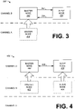
FIG. 4 depicts an embodiment of awireless network 400 in which amaster node 402 andslave node 404 may switch to communicate on an entirely different channel upon the slave node accepting the designated configuration sent by themaster node 402. That is, building on the embodiments ofFIGs. 1 and3 , once aslave node 404 has transmitted the confirmation frame, themaster node 402 may configure itself to communicate on the same Basic Service Set with the same configuration (e.g. encryption key, channel, etc.) as theslave node 404. Accordingly,master node 402 may change channels according to the channel designated in the configuration frame. Accordingly, in the embodiment ofFIG. 4 ,slave node 404 has been designated to communicate on Channel C by the configuration frame transmitted bymaster node 402. Thus, oncemaster node 402 receives the confirmation frame on Channel B, indicating thatslave node 404 will accept the configuration (and thus switch to Channel C),master node 402 configures itself with the BSSID, key, and any other necessary network parameters such thatmaster node 404 may communicate withslave node 404 on ChannelC. Master node 402 may then switch to Channel C to establish a connection with the Basic Service Set having the BSSID, and may establish thecommunication connection 406 withslave node 404. - The embodiment of
FIG. 4 illustrates that, if desired, the connection and remote configuration systems and methods may be used to designate a completely new Basic Service Set for the purpose of providing communication between a master node and a slave node. The new Basic Service Set may, for example, be an ad-hoc network in which both clients reside on the same channel during communications. The new Basic Service Set may, for example, be a temporary Basic Service Set set up for a limited time. The temporary Basic Service Set may be configured to use a new BSSID, new security key, and channel selected by the master node, and this configuration can be supplied in the configuration frame transmitted to the slave node. The new BSSID, security key, and/or channel, could be, for example, preconfigured or generated randomly by the master node. - Although the master node and slave node may be configured to communicate on the same channel after the slave is configured, this is not necessary. Rather, the master node may remotely configure the slave node to communicate according to any Basic Service Set configuration, and thus may designate that the slave node join a completely different Basic Service Set on a completely different channel than the master node. Although this may not result in the ability of the master and slave nodes to communicate, it illustrates that the remote configuration may be used to configure wireless nodes to attach to any Basic Service Set (rather than just the Basic Service Set of the master node).
- Now that a general understanding of the potential environments for the disclosed connection and remote configuration systems and methods have been described,
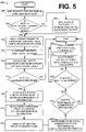
FIG. 5 depicts an exemplary flow diagram 500 of the connection and remote configuration method used to provide the connection and configuration described with respect toFIGs. 1-4 . Specifically, atblock 502, a master node constructs a remote configuration frame that includes configuration information to be transmitted to the slave node. The configuration information may be used by a slave node to establish a connection with a designated Basic Service Set. A remote configuration frame may be any known 802.11 frame (e.g. data frames, tkip frames, etc.) or could be a proprietary frame format, for example. As discussed with respect toFIG. 1 , the configuration information, for example, may designate network configuration parameters such as the SSID of the Basic Service Set to join, the BSSID of the Basic Service Set to join, security information, and possibly a channel that the slave node should use as its base channel. The security information, for example, may include authentication information and/or encryption information such as an encryption key of the Basic Service Set, a password, an unlocking token, or the encryption method used by the Basic Service Set. The password may, for example, be a shared password that may be used by the nodes to derive an encryption key. - In some embodiments, a slave node may be remotely configured only by certain authorized master nodes. For example, the slave node may be "locked" from remote configuration until the slave node receives an unlocking token from a master node, which may be transmitted inside the first configuration frame. The unlocking token may, for example, be thought of as a password that the slave node is preconfigured to recognize. Thus, the slave node may be configured to extract and recognize the unlocking token in a received configuration frame as being transmitted by an authorized master node. Upon recognizing the unlock token in the received configuration frame, the slave node may then extract the remaining configuration information from the configuration frame to determine the network configuration parameters. If the token is not recognized, the slave node may discard the frame. The token may also be used to identify the master node in further communications. Using a token to establish communications is especially useful when the encryption key for the configuration frame is determined using a security method without authentication.
- At
decision 504, the master node may determine whether the slave node currently resides on the same channel as the master node. For example, the master node may compare its current channel to the known channel of the slave node's. If the master node is not communicating on the same channel as the slave node (the NO condition), atblock 506, the master node may switch to communicate on the channel as described with respect toFIG. 3 . - Once the master node and the slave node are communicating on the same channel, (e.g. the YES condition), at
block 508, the master node may instruct the slave node to connect to a Basic Service Set designated by the master node. Specifically, the master node may transmit a configuration frame to slave node using the known address of the slave node as the destination. The master node may transmit the configuration frame after waiting for the slave node's receive window. - In a secure wireless network, the configuration frame may be transmitted as an encrypted frame to the slave node. Configuration frame may be encrypted using any well known encryption algorithm, for example, with a key derived from a pre-shared password (e.g. pre-shared key (PSK)) or through a WiFi Protected Access Pre-shared Key (WPA-PSK), for example.
- Accordingly, a shared key may be needed for the master node to encrypt, and the slave node to decrypt, the configuration frame. The shared key may already be preconfigured in the slave node and supplied to the master node (e.g. through a user interface). Additionally, methods for generating keys between nodes without authorization are known and also may be used. One key derivation algorithm, for example, may be based on the IEEE 802.11(i) standard.
- Even if the received frame is able to be decrypted by the receiving node, the receiving node may be configured to ignore frames that are not specifically destined for the receiving node. That is, receiving nodes typically discard packets that do not have a matching destination address and/or SSID, for example. Accordingly, the configuration frame may include a frame identifier in the header of the MAC frame that signals to a receiving node that the configuration frame should not be discarded (and should be used for configuration).
- For example, an 802.11 MAC frame may include a number of fields including, for example, the frame body (e.g. containing the data), error code information (e.g. cyclic redundancy check (CRC) information), as well as a header. The 802.11 MAC header specifies several information fields, including a frame control field, a duration ID, sequence control, and a number of address fields which may be referred to as the "Address 1," "Address 2," "Address 3," and "Address 4" fields.
- The Address 1 field may contain the address of the receiving wireless node (destination) of the frame, and the Address 2 field may contain the address of the transmitting wireless node (source) of the frame. The Address 3 field may contain the BSSID. Wireless nodes may be configured to filter received frames based on the BSSID in the Address 3 field of the header. Thus, the wireless node may be configured to forward the received frame to the higher protocol layers (e.g. Open Systems Interconnection (OSI) layers) only if the BSSID matches the configured BSSID.
- Accordingly, the configuration frame may include an identifier (herein a "remote configuration frame identifier"). Although the identifier could be located in other portions of the frame, according to some embodiments the configuration frame could include the identifier in the header location where the BSSID is normally found, such as Address 3 of the MAC header. The remote configuration frame identifier could be a company-specific multicast MAC address preconfigured in the slave node, for example. The receiving node is configured to recognize the remote configuration frame identifier as being associated with configuration frames. Thus, upon receipt of a frame having this remote configuration frame identifier, rather than discarding the frame (e.g. since the Address 3 field may not reference the BSSID to which the slave node belongs, if any), the processor in the slave node is configured to extract the configuration information from the configuration frame.
- The remote configuration frame identifier may be configured next to the BSSID of the network the slave node is already connected with (if any), so that the slave node will always be able to receive configuration frames, irrespective of the connection state. That is, the slave node may be connected with a Basic Service Set with BSSID 1, while the slave node also still filters configuration frames which are transmitted to BSSID2. Thus, BSSID2 is configured 'next to' BSSID1.
- At
block 510, the slave node may be configured to receive the configuration frame transmitted by the master node atblock 506. Atblock 512, the slave node parses the received configuration frame to extract the header information from the configuration frame. Accordingly, the header information may include the remote configuration frame identifier. - At
decision 514, the slave node determines whether the received frame is indeed a configuration frame that it recognizes. For example, the slave node may compare the remote configuration frame identifier to a stored configuration key. If the key does not match the remote configuration frame identifier in the configuration frame, the slave node determines that the frame is not a configuration frame (the NO condition). Accordingly, the slave node may perform other unrelated processing on the frame, or may discard the frame altogether. However, if the key does match the remote configuration frame identifier in the configuration frame, the slave node may determine that the frame is a configuration frame (the YES condition) and may proceed to extract the configuration information from the frame. - Thus, at
block 516, once it is determined that the received frame is a configuration frame, the slave node may be configured to parse the body of the configuration frame to extract the configuration information from the configuration frame. Atblock 518, once the configuration information has been extracted, the slave node configures itself according to the configuration parameters designated by the configuration information in the configuration frame. For example, the slave node may set its SSID to a designated SSID of the Basic Service Set to join, set its encryption key to the designated encryption key, and set its channel to the designated channel. Of course, these are merely examples, and it should be understood that any other configuration parameters may be designated by the configuration information sent in the configuration frame, and the slave node may be configured to configure itself according to the other corresponding configuration parameters. - Upon accepting the configuration and establishing the connection at
block 520, the slave node may respond with a confirmation frame, which serves as an acknowledgement of the acceptance of the configuration. The confirmation frame is addressed and transmitted to the master node by using the MAC address and other communication information that may be extracted from the header of the configuration frame. The confirmation frame may also include other information. In one embodiment, the confirmation frame may indicate that the configuration was denied. In such an embodiment, the confirmation frame may include an indication of the reason for the decline of the configuration (e.g. invalid parameters, etc.). For example, the reason may be supplied as a code which the master node may use to determine the cause of the decline of the configuration. - At
block 522, once the confirmation frame is transmitted to the master node, a connection may then be established with the designated Basic Service Set using the network configuration parameters designated by the extracted configuration information. The systems and methods for establishing a connection to a Basic Service Set are outside of the scope of this disclosure. For example, for 802.11 networks, this method is defined by the 802.11 standard, and these methods would be the same as if the slave node were manually configured. - In some embodiments, the master node does not need to communicate with the slave node. Rather, the master node is used to remotely configure the slave node to communicate on a designated Basic Service Set, without further action. Thus, in this case, at
decision 524, the NO condition ends the client connection and remote configuration. - In some embodiments, it may be desirable for the master node to establish a communication link with the slave node (
decision 524, the YES condition). To establish the communication link with the slave node, the master node may join the Basic Service Set that the slave node has joined. Thus, atdecision 526, the master node compares its existing communication parameters to the communication parameters designated in the configuration information sent to the slave node. If the master node is already configured according to these parameters such that it can already communicate with the slave node (the YES condition), the master node may begin communication atblock 530. However, if the master node is not configured such that it can communicate with the slave node (the NO condition), atblock 528, the master node configures itself with the necessary network configuration parameters (BSSID, key, channel, etc.) and connects to the Basic Service Set using these configuration parameters. This may, for example, require changing channels to the slave node's channel, as described with respect toFIG. 3 and 4 . - Thus, it should be understood that, in some embodiments, the configuration supplied to the slave node by the master node in the configuration frame may, for example, enable the slave node to join and communicate on the Basic Service Set that the master node currently belongs (if any). Likewise, in some embodiments, the configuration enables the slave node to join and communicate on a different Basic Service Set than the master node.
- Further, in some cases it may be desirable to instruct the slave node to join a new, temporary Basic Service Set for the purpose of a temporary connection with a master node, or other wireless nodes. Accordingly, the client connection and configuration systems and methods may enable wireless nodes (e.g. clients) to connect with each other through a Temporary Basic Service Set (TBSS). The TBSS may be thought of as a temporary Basic Service Set, which may have a SSID, a BSSID, and a session key which may, for example, be preconfigured or randomly generated by the master node.
- When embodiments of the described connection and remote configuration systems and methods are used to configure an infrastructure network, a configuration frame can also be transmitted by an access point to instruct other wireless nodes, such as wireless clients, to join the infrastructure network of the access point. The access point may also instruct the wireless clients to join a Basic Service Set other than the Basic Service Set the access point resides within. This may, for example, be used to manage network congestion (e.g. by shifting wireless clients to balance network traffic).
- However, when the master node is an access point, there is some risk of losing packets communicated to the access point by other wireless nodes if the access point is required to switch to the base channel of a slave node to be remotely configured. However, one embodiment may use a Network Allocation Vector (NAV) to prevent the non-receipt of data. Specifically, 802.11 wireless nodes may use a virtual carrier sense that updates a NAV. The NAV duration, for example, may be set by adding a non-zero duration inside the MAC header. Stations that receive the MAC header with the duration will assume that the network is busy for this period of time (and thus, will not transmit during this time). Accordingly, in one embodiment, the access point may set a NAV on its base channel before switching to the base channel of the client to be configured. That is, the access point may broadcast a frame designating a NAV duration such that receiving nodes on the base channel are instructed not to transmit frames to the access point during this NAV duration. The access point may then change channels to perform the remote configuration of the slave node during this NAV duration. Accordingly, the access point prevents the loss of packets while the access point switches off its base channel to communicate with the slave node to be configured.
- According to yet another embodiment in which the master node is an access point, the access point may prevent data loss by waiting until the access point receives, for example, a probe request frame from the slave node before transmitting a configuration frame to the slave node. That is, as defined by the 802.11 standard, a probe request frame may be periodically broadcast by wireless nodes (e.g. for the purpose of announcing themselves to access points). The probe requests are transmitted by the wireless nodes during an active scan of each channel. Effectively, rather than switching to the channel of the slave node, the access point waits for the slave node to switch to the access point's channel and send the access point a probe request frame. Upon the access point's receipt of the probe request frame, a configuration frame is transmitted to the slave node from the access point. Accordingly, the slave node is instructed to configure itself according to the network configuration parameters designated by the configuration information contained within the configuration frame. Waiting for a probe request may result in a longer delay than an embodiment using a NAV. However, one potential advantage is that the access point is not required to leave the access point's base channel. Thus, communications between wireless nodes and the access point are not disturbed.
- In addition to being useful for configuring wireless clients, the connection and remote configuration embodiments may also be used to instruct an access point to start an infrastructure network. For example the systems and methods may be used when installing a new access point, if an access point loses its configuration, or if it is desired to switch the access point to communicate on a new Basic Service Set. Generally, in this scenario, the access point is the slave node, and any other wireless node may be the master node.
Claims (19)
- A method for remote configuration of a node comprising:transmitting, over an IEEE 802.11-based wireless network, configuration information from a first node (102) to a second node (104) over a wireless communication channel shared by the first and second nodes, the configuration information designating network configuration parameters to remotely configure the second node for network communications, the network configuration parameters at least including a network identifier of an IEEE 802.11-based wireless network for the second node to join and encryption information for enabling the second node to establish a network connection; andtransmitting the configuration information in a configuration frame, the configuration frame recognized by the second node as an instruction for configuring the second node for network communications according to the configuration information, wherein the first node generates the frame by including a remote configuration frame identifier in the frame, the remote configuration frame identifier specifying that the frame is a configuration frame,in case of accepting the configuration information by the second node, receiving a confirmation from the second node serving as an acknowledgement of the acceptance of the configuration in response to accepting the configuration information; andin case of denying the configuration information by the second node, receiving a confirmation from the second node indicating that the configuration was denied.
- The method of claim 1, wherein the step of embedding a network identifier includes embedding a basic service set identifier, BSSID, or a service set identifier, SSID, in the configuration information, and/or the method further includes embedding channel information in the configuration information.
- The method of claim 1 or 2, wherein the first node is an access point, and the access point broadcasts a network allocation vector, NAV, on the base channel of the access point, the NAV designating a duration of time for nodes receiving the NAV not to transmit data to the access point; and
transmitting the configuration information to the second node, on the second node's channel, at a time during the designated duration of time. - The method of any of claims 1 - 3, wherein the first node is an access point residing on a base channel, and the access point receives a probe request from the second node on the base channel, and upon receiving the probe request, transmits the configuration information to the second node at a time when the second node is communicating on the base channel of the access point.
- The method of any of claims 1 - 4, further comprising:
establishing communications between the first node and the second node on a channel designated by the configuration information, after receiving the confirmation. - The method of any of claims 1 - 5, wherein the second node recognizes the remote configuration frame identifier in a received frame, and upon recognizing the remote configuration frame identifier in the received frame, the second node extracts the configuration information from the configuration frame to determine the network configuration parameters.
- A method for remote configuration of a node comprising:processing configuration information received at a second node (104) from a first node (102), the configuration information transmitted to the second node over a wireless communication channel shared by the first and second nodes, the configuration information designating network configuration parameters to remotely configure the second node for network communications, the network configuration parameters at least including a network identifier of an IEEE 802.11-based wireless network for the second node to join and encryption information for enabling the second node to establish a network connection;receiving, over an IEEE 802.11-based wireless network, the configuration information in a configuration frame, the configuration frame recognized by the second node as an instruction for configuring the second node for network communications according to the configuration information, wherein the frame includes a remote configuration frame identifier in the frame, the remote configuration frame identifier specifying that the frame is a configuration frame;accepting the configuration information by configuring the second node according to the designated network configuration parameters or denying the configuration information; andin case of accepting the configuration information, transmitting a confirmation to the first node serving as an acknowledgement of the acceptance of the configuration in response to accepting the configuration information; andin case of denying the configuration information, transmitting a confirmation to the first node indicating that the configuration was denied.
- A system for remotely configuring a wireless node, the system comprising:a wireless network having at least one shared communication channel;a master node (102) comprising:a processor (110) configured to generate a frame including configuration information designating network configuration parameters to remotely configure a wireless node for network communications, the network configuration parameters at least including a network identifier of an IEEE 802.1 1-based wireless network for a slave node to join and encryption information for enabling the slave node to establish a network connection, wherein the frame includes a remote configuration frame identifier in the frame, the remote configuration frame identifier specifying that the frame is a configuration frame; anda transmitter (106) for sending, over an IEEE 802.11-based wireless network, the configuration information over the at least one shared communication channel; anda receiver for receiving a confirmation from the slave node serving as an acknowledgement of the acceptance of the configuration, in case of accepting the configuration information by the slave node, and for receiving a confirmation from the slave node indicating that the configuration was denied, in case of denying the configuration information by the slave node, andthe slave node (104) comprising:a receiver for receiving the frame including the configuration information from the master node on the at least one shared communication channel; anda processor configured to accept the configuration information by configuring the slave node to communicate according to the designated network configuration parameters or deny the configuration information, and the processor further configured to generate both of the following: in case of accepting the configuration information, a confirmation serving as an acknowledgement of the acceptance of the configuration, and, in case of denying the configuration information, a confirmation indicating that the configuration was denied; anda transmitter for transmitting the confirmation to the master node in response to accepting or denying the configuration information.
- The system of claim 8, wherein the processor of the slave node is configured to:
recognize the remote configuration frame identifier in a received frame, and upon recognizing the remote configuration frame identifier in the received frame, extract the configuration information from the configuration frame to determine the network configuration parameters. - A master node (102) comprising:a processor (110) configured to generate a frame by:including a remote configuration frame identifier in the frame, the remote configuration frame identifier for specifying that the frame is a configuration frame; andincluding configuration information in the frame, the configuration information designating network configuration parameters to remotely configure a slave node for network communications, the network configuration parameters at least including a network identifier of an IEEE 802.11-based wireless network for a slave node to join and encryption information for enabling the slave node to establish a network connection; anda transmitter (106) for transmitting, over an IEEE 802.11-based wireless network, the frame from the master node to the slave node over a wireless communication channel shared by the master node and the slave node; anda receiver for receiving a confirmation from the slave node serving as an acknowledgement of the acceptance of the configuration, in case of accepting the configuration information by the slave node, and for receiving a confirmation from the slave node indicating that the configuration was denied, in case of denying the configuration information by the slave node.
- A slave node (104) comprising:a processor configured to recognize a remote configuration frame identifier in a received frame wirelessly transmitted, over an IEEE 802.11-based wireless network, from a master node over a wireless communication channel, and upon recognizing the remote configuration frame identifier in the received frame, the processor configured to extract configuration information from the configuration frame to determine network configuration parameters to remotely configure the slave node for network communications, the network configuration parameters at least including a network identifier of an IEEE 802.11-based wireless network for the slave node to join and encryption information for enabling the slave node to establish a network connection,the processor further configured to accept the configuration information by configuring the slave node to communicate according to the designated network configuration parameters or deny the configuration, and the processor further configured to generate both of the following: in case of accepting the configuration information, a confirmation serving as an acknowledgement of the acceptance of the configuration, and, in case of denying the configuration information, a confirmation indicating that the configuration was denied; anda transmitter for transmitting the confirmation to the master node in response to accepting or denying the configuration information.
- The slave node of claim 11, wherein the network identifier is a basic service set identifier, BSSID, or a service set identifier, SSID.
- The slave node of claim 11 or 12, wherein channel information is embedded in the configuration information designating a channel that the slave node should use as its base channel.
- The slave node of any of claims 11 - 13, wherein the processor is further configured to extract a network identifier of a network for the slave node to join from the configuration information.
- The slave node of any of claims 11 - 14, wherein the confirmation is a confirmation frame.
- The slave node of any of claims 11 - 15, configured to establish communications between the master node and the slave node on a channel designated by the configuration information.
- The slave node of any of claims 11 - 16, wherein the encryption information comprises an encryption key or can be used for indirectly determining the encryption key.
- The slave node of any of claims 11 - 17, wherein the slave node is further configured for switching channels and transmitting probe requests to the master node during an active scan of each channel.
- The slave node of any of claims 11 - 18, wherein the slave node is a cellular phone.
Applications Claiming Priority (3)
| Application Number | Priority Date | Filing Date | Title |
|---|---|---|---|
| US63920804P | 2004-12-23 | 2004-12-23 | |
| PCT/US2005/046657 WO2006071741A2 (en) | 2004-12-23 | 2005-12-21 | Systems and methods for the connection and remote configuration of wireless clients |
| EP05855249.8A EP1829398B1 (en) | 2004-12-23 | 2005-12-21 | Systems and methods for the connection and remote configuration of wireless clients |
Related Parent Applications (2)
| Application Number | Title | Priority Date | Filing Date |
|---|---|---|---|
| EP05855249.8A Division-Into EP1829398B1 (en) | 2004-12-23 | 2005-12-21 | Systems and methods for the connection and remote configuration of wireless clients |
| EP05855249.8A Division EP1829398B1 (en) | 2004-12-23 | 2005-12-21 | Systems and methods for the connection and remote configuration of wireless clients |
Publications (2)
| Publication Number | Publication Date |
|---|---|
| EP3301958A1 EP3301958A1 (en) | 2018-04-04 |
| EP3301958B1 true EP3301958B1 (en) | 2022-09-21 |
Family
ID=36615432
Family Applications (2)
| Application Number | Title | Priority Date | Filing Date |
|---|---|---|---|
| EP05855249.8A Active EP1829398B1 (en) | 2004-12-23 | 2005-12-21 | Systems and methods for the connection and remote configuration of wireless clients |
| EP17201703.0A Active EP3301958B1 (en) | 2004-12-23 | 2005-12-21 | Systems and methods for the connection and remote configuration of wireless clients |
Family Applications Before (1)
| Application Number | Title | Priority Date | Filing Date |
|---|---|---|---|
| EP05855249.8A Active EP1829398B1 (en) | 2004-12-23 | 2005-12-21 | Systems and methods for the connection and remote configuration of wireless clients |
Country Status (4)
| Country | Link |
|---|---|
| US (1) | US7929504B2 (en) |
| EP (2) | EP1829398B1 (en) |
| CN (1) | CN101084687B (en) |
| WO (1) | WO2006071741A2 (en) |
Families Citing this family (47)
| Publication number | Priority date | Publication date | Assignee | Title |
|---|---|---|---|---|
| US7864796B1 (en) * | 2005-04-04 | 2011-01-04 | Avaya Inc. | Start-to-finish reservations in distributed MAC protocols for wireless LANs |
| JP4829635B2 (en) | 2006-02-17 | 2011-12-07 | キヤノン株式会社 | Communication apparatus, communication method, network configuration method, and communication system |
| US7970013B2 (en) * | 2006-06-16 | 2011-06-28 | Airdefense, Inc. | Systems and methods for wireless network content filtering |
| US8619623B2 (en) * | 2006-08-08 | 2013-12-31 | Marvell World Trade Ltd. | Ad-hoc simple configuration |
| US8281392B2 (en) | 2006-08-11 | 2012-10-02 | Airdefense, Inc. | Methods and systems for wired equivalent privacy and Wi-Fi protected access protection |
| US8233456B1 (en) | 2006-10-16 | 2012-07-31 | Marvell International Ltd. | Power save mechanisms for dynamic ad-hoc networks |
| US8732315B2 (en) | 2006-10-16 | 2014-05-20 | Marvell International Ltd. | Automatic ad-hoc network creation and coalescing using WiFi protected setup |
| US9308455B1 (en) | 2006-10-25 | 2016-04-12 | Marvell International Ltd. | System and method for gaming in an ad-hoc network |
| US8718555B2 (en) | 2006-11-10 | 2014-05-06 | Powerwave Cognition, Inc. | Method and system for using selected bearer channels |
| TWI338521B (en) * | 2006-11-17 | 2011-03-01 | Hon Hai Prec Ind Co Ltd | Access point and method for switching channel thereof |
| CN101193025B (en) * | 2006-11-24 | 2010-05-19 | 鸿富锦精密工业(深圳)有限公司 | Access point and its channel switching method |
| US9060325B2 (en) * | 2006-12-04 | 2015-06-16 | Intel Corporation | Method and apparatus for creating and connecting to an ad hoc wireless cell |
| EP1936878A1 (en) * | 2006-12-22 | 2008-06-25 | IBBT vzw | Method for channel assignment in multi-radio wireless mesh networks and corresponding network node |
| US7720086B2 (en) * | 2007-03-19 | 2010-05-18 | Microsoft Corporation | Distributed overlay multi-channel media access control for wireless ad hoc networks |
| US20090010183A1 (en) * | 2007-07-03 | 2009-01-08 | Arcadyan Technology Corporation | Function configuration method of electronic apparatuses |
| US8429729B1 (en) * | 2007-07-31 | 2013-04-23 | Marvell International Ltd. | Secure wireless network setup using multicast packets |
| JP5125304B2 (en) | 2007-08-13 | 2013-01-23 | ブラザー工業株式会社 | Wireless communication connection system and network device |
| JP5171167B2 (en) * | 2007-09-05 | 2013-03-27 | キヤノン株式会社 | COMMUNICATION DEVICE FOR COMMUNICATION PARAMETER SETTING PROCESS, CONTROL METHOD FOR COMMUNICATION DEVICE, AND COMPUTER PROGRAM |
| GB2452753A (en) * | 2007-09-13 | 2009-03-18 | Iti Scotland Ltd | Channel switching in a communication network |
| US7814182B2 (en) * | 2008-03-20 | 2010-10-12 | International Business Machines Corporation | Ethernet virtualization using automatic self-configuration of logic |
| US8073449B2 (en) * | 2008-10-30 | 2011-12-06 | Aruba Networks, Inc. | Wireless macro cell overlay |
| CN102638830A (en) * | 2011-02-11 | 2012-08-15 | 黄鹉胜 | Plug-and-play wireless network extension system and automatic access method thereof |
| CN102387042B (en) * | 2011-11-22 | 2014-03-12 | 华为技术有限公司 | Automatic configuration method and system as well as network node |
| US8955097B2 (en) * | 2011-12-13 | 2015-02-10 | Mcafee, Inc. | Timing management in a large firewall cluster |
| US20130227647A1 (en) * | 2012-02-28 | 2013-08-29 | Apple Inc. | Shared network access via a peer-to-peer link |
| US9161265B2 (en) * | 2012-04-20 | 2015-10-13 | Futurewei Technologies AG | System and method for basic service set association |
| US8665744B2 (en) * | 2012-05-18 | 2014-03-04 | Gainspan Corporation | Convenient provisioning of embedded devices with WiFi capability |
| EP2731298A1 (en) * | 2012-11-07 | 2014-05-14 | Siemens Aktiengesellschaft | Communications system |
| US9338130B2 (en) * | 2013-02-11 | 2016-05-10 | Broadcom Corporation | Apparatus and method to register Wi-Fi clients on a Wi-Fi network |
| CN104158676A (en) * | 2013-05-14 | 2014-11-19 | 中怡(苏州)科技有限公司 | Setting method of wireless network, communication system and far-end device |
| CN105009513B (en) * | 2013-12-03 | 2018-09-28 | 华为技术有限公司 | The newer method of node device, node device and the distributed system of distributed system |
| US10057813B1 (en) * | 2014-05-09 | 2018-08-21 | Plume Design, Inc. | Onboarding and configuring Wi-Fi enabled devices |
| US10779161B2 (en) | 2014-09-15 | 2020-09-15 | Nokia Solutions And Networks Oy | Delivery of cellular network insights to subscriber devices through SSID via cellular system information block |
| WO2016041569A1 (en) * | 2014-09-15 | 2016-03-24 | Nokia Solutions And Networks Oy | Wi-fi signaling network insight delivery |
| US9992142B2 (en) * | 2014-11-10 | 2018-06-05 | Cisco Technology, Inc. | Messages from absent participants in online conferencing |
| CN104602112A (en) * | 2014-12-12 | 2015-05-06 | 小米科技有限责任公司 | Configuration method and device |
| JP6582760B2 (en) | 2015-09-03 | 2019-10-02 | ブラザー工業株式会社 | Communication device |
| JP6534356B2 (en) * | 2016-03-07 | 2019-06-26 | アルパイン株式会社 | Communication apparatus, communication control method and communication system |
| US10244536B1 (en) * | 2016-08-31 | 2019-03-26 | Marvell International Ltd. | Method and apparatus for determining whether a secondary channel is idle |
| CN106254147B (en) * | 2016-09-08 | 2019-06-28 | 珠海全志科技股份有限公司 | It is a kind of for the configuration method of Wi-Fi network, internet-of-things terminal and control terminal |
| US10728756B2 (en) | 2016-09-23 | 2020-07-28 | Qualcomm Incorporated | Access stratum security for efficient packet processing |
| CN108966256A (en) * | 2018-09-30 | 2018-12-07 | 普联技术有限公司 | A kind of wireless device configuration method, system and equipment |
| CN112399412B (en) | 2019-08-19 | 2023-03-21 | 阿里巴巴集团控股有限公司 | Session establishment method and device, and communication system |
| CN113766590A (en) * | 2020-06-05 | 2021-12-07 | 平头哥(上海)半导体技术有限公司 | Method and wireless device for application in wireless networking |
| CN114095918B (en) * | 2020-07-31 | 2023-10-13 | 华为技术有限公司 | Network distribution method and system |
| DE102021105402A1 (en) * | 2021-03-05 | 2022-09-08 | Infineon Technologies Ag | DATA PROCESSING DEVICE AND METHOD FOR TRANSMITTING DATA VIA A BUS |
| CN116193412B (en) * | 2023-03-02 | 2024-02-06 | 上海物骐微电子有限公司 | Communication system, method and storage medium of Bluetooth low-power-consumption audio network |
Citations (10)
| Publication number | Priority date | Publication date | Assignee | Title |
|---|---|---|---|---|
| US20020142765A1 (en) | 2001-03-30 | 2002-10-03 | Rhoads Monte J. | Network appliance wireless configuration interface |
| US20030061320A1 (en) | 2001-09-27 | 2003-03-27 | Rajeev Grover | Configuring a network parameter to a device |
| US20030123405A1 (en) | 2001-12-27 | 2003-07-03 | Koninklijke Philips Electronics N.V. | Overlapping network allocation vector (ONAV) for avoiding collision in the IEEE 802.11 WLAN operating under HCF |
| US20030212802A1 (en) | 2002-05-09 | 2003-11-13 | Gateway, Inc. | Proximity network encryption and setup |
| US20040030895A1 (en) | 2002-08-09 | 2004-02-12 | Canon Kabushiki Kaisha | Network configuration method and communication system and apparatus |
| US20040039817A1 (en) | 2002-08-26 | 2004-02-26 | Lee Mai Tranh | Enhanced algorithm for initial AP selection and roaming |
| WO2004062202A2 (en) | 2002-12-30 | 2004-07-22 | Intel Corporation | Method and apparatus to establish communication |
| US20040250072A1 (en) | 1998-06-10 | 2004-12-09 | Tatu Ylonen | Network connectable device and method for its installation and configuration |
| US20040246922A1 (en) | 2003-06-03 | 2004-12-09 | Jiandong Ruan | Making roaming decisions based on association qualities between wireless devices and wireless access points |
| US20050044196A1 (en) | 2003-08-08 | 2005-02-24 | Pullen Benjamin A. | Method of and system for host based configuration of network devices |
Family Cites Families (10)
| Publication number | Priority date | Publication date | Assignee | Title |
|---|---|---|---|---|
| US6934752B1 (en) * | 2000-03-23 | 2005-08-23 | Sharewave, Inc. | Quality of service extensions for multimedia applications in wireless computer networks |
| US6850502B1 (en) | 2000-10-30 | 2005-02-01 | Radiant Networks, Plc | Join process method for admitting a node to a wireless mesh network |
| US6961319B2 (en) | 2001-07-16 | 2005-11-01 | International Business Machines Corporation | Methods and arrangements for distribution tree development |
| JP3915481B2 (en) * | 2001-11-14 | 2007-05-16 | セイコーエプソン株式会社 | Wireless communication device |
| US7146130B2 (en) * | 2003-02-24 | 2006-12-05 | Qualcomm Incorporated | Wireless local access network system detection and selection |
| WO2005004437A1 (en) | 2003-06-25 | 2005-01-13 | Hotspot Wireless Devices, Inc. | Systems and metods using multiprotocol communication |
| US20050048997A1 (en) * | 2003-09-02 | 2005-03-03 | Mike Grobler | Wireless connectivity module |
| US7447232B2 (en) | 2003-09-30 | 2008-11-04 | Intel Corporation | Data burst transmission methods in WLAN devices and systems |
| US7016684B2 (en) | 2003-12-01 | 2006-03-21 | Interdigital Technology Corporation | Wireless communication method and apparatus for implementing access point startup and initial channel selection processes |
| US7706337B2 (en) | 2004-10-22 | 2010-04-27 | Motorola, Inc. | Method for performing neighbor discovery in a multi-tier WLAN |
-
2005
- 2005-12-21 CN CN200580043707XA patent/CN101084687B/en active Active
- 2005-12-21 US US11/314,143 patent/US7929504B2/en active Active
- 2005-12-21 EP EP05855249.8A patent/EP1829398B1/en active Active
- 2005-12-21 EP EP17201703.0A patent/EP3301958B1/en active Active
- 2005-12-21 WO PCT/US2005/046657 patent/WO2006071741A2/en active Application Filing
Patent Citations (10)
| Publication number | Priority date | Publication date | Assignee | Title |
|---|---|---|---|---|
| US20040250072A1 (en) | 1998-06-10 | 2004-12-09 | Tatu Ylonen | Network connectable device and method for its installation and configuration |
| US20020142765A1 (en) | 2001-03-30 | 2002-10-03 | Rhoads Monte J. | Network appliance wireless configuration interface |
| US20030061320A1 (en) | 2001-09-27 | 2003-03-27 | Rajeev Grover | Configuring a network parameter to a device |
| US20030123405A1 (en) | 2001-12-27 | 2003-07-03 | Koninklijke Philips Electronics N.V. | Overlapping network allocation vector (ONAV) for avoiding collision in the IEEE 802.11 WLAN operating under HCF |
| US20030212802A1 (en) | 2002-05-09 | 2003-11-13 | Gateway, Inc. | Proximity network encryption and setup |
| US20040030895A1 (en) | 2002-08-09 | 2004-02-12 | Canon Kabushiki Kaisha | Network configuration method and communication system and apparatus |
| US20040039817A1 (en) | 2002-08-26 | 2004-02-26 | Lee Mai Tranh | Enhanced algorithm for initial AP selection and roaming |
| WO2004062202A2 (en) | 2002-12-30 | 2004-07-22 | Intel Corporation | Method and apparatus to establish communication |
| US20040246922A1 (en) | 2003-06-03 | 2004-12-09 | Jiandong Ruan | Making roaming decisions based on association qualities between wireless devices and wireless access points |
| US20050044196A1 (en) | 2003-08-08 | 2005-02-24 | Pullen Benjamin A. | Method of and system for host based configuration of network devices |
Also Published As
| Publication number | Publication date |
|---|---|
| US7929504B2 (en) | 2011-04-19 |
| EP1829398A2 (en) | 2007-09-05 |
| EP1829398B1 (en) | 2018-01-17 |
| EP1829398A4 (en) | 2012-10-31 |
| US20060153156A1 (en) | 2006-07-13 |
| WO2006071741A3 (en) | 2007-02-08 |
| EP3301958A1 (en) | 2018-04-04 |
| CN101084687B (en) | 2011-05-18 |
| CN101084687A (en) | 2007-12-05 |
| WO2006071741A2 (en) | 2006-07-06 |
Similar Documents
| Publication | Publication Date | Title |
|---|---|---|
| EP3301958B1 (en) | Systems and methods for the connection and remote configuration of wireless clients | |
| US11895498B2 (en) | Method and device for negotiating security and integrity algorithms | |
| US9479935B2 (en) | Configurator forced client network rejoining | |
| US7814322B2 (en) | Discovery and authentication scheme for wireless mesh networks | |
| EP1515510B1 (en) | Method and system for providing multiple encryption in a multi-band multi-protocol hybrid wired/wireless network | |
| US8036183B2 (en) | Method and system for transporting configuration protocol messages across a distribution system (DS) in a wireless local area network (WLAN) | |
| EP1484856A1 (en) | The method for distributes the encrypted key in wireless lan | |
| US20070190973A1 (en) | Base station, wireless communication systems, base station control programs and base station control methods | |
| CN104854892A (en) | Method and device for deriving WLAN security context from WWAN security context | |
| EP3446538A1 (en) | System and method for device identification and authentication | |
| CN113676904B (en) | Slice authentication method and device | |
| WO2019158117A1 (en) | System and method for providing security in a wireless communications system with user plane separation | |
| WO2011064858A1 (en) | Wireless authentication terminal | |
| EP3311599B1 (en) | Ultra dense network security architecture and method | |
| WO2015064475A1 (en) | Communication control method, authentication server, and user equipment | |
| EP1547299A1 (en) | Method and system for providing multiple encryption in a multi-band multi-protocol hybrid wired/wireless network | |
| EP4262149A1 (en) | Method and apparatus for authenticating user equipment in wireless communication system |
Legal Events
| Date | Code | Title | Description |
|---|---|---|---|
| PUAI | Public reference made under article 153(3) epc to a published international application that has entered the european phase |
Free format text: ORIGINAL CODE: 0009012 |
|
| STAA | Information on the status of an ep patent application or granted ep patent |
Free format text: STATUS: THE APPLICATION HAS BEEN PUBLISHED |
|
| AC | Divisional application: reference to earlier application |
Ref document number: 1829398 Country of ref document: EP Kind code of ref document: P |
|
| AK | Designated contracting states |
Kind code of ref document: A1 Designated state(s): AT BE BG CH CY CZ DE DK EE ES FI FR GB GR HU IE IS IT LI LT LU LV MC NL PL PT RO SE SI SK TR |
|
| STAA | Information on the status of an ep patent application or granted ep patent |
Free format text: STATUS: REQUEST FOR EXAMINATION WAS MADE |
|
| 17P | Request for examination filed |
Effective date: 20180928 |
|
| RBV | Designated contracting states (corrected) |
Designated state(s): AT BE BG CH CY CZ DE DK EE ES FI FR GB GR HU IE IS IT LI LT LU LV MC NL PL PT RO SE SI SK TR |
|
| STAA | Information on the status of an ep patent application or granted ep patent |
Free format text: STATUS: EXAMINATION IS IN PROGRESS |
|
| 17Q | First examination report despatched |
Effective date: 20190708 |
|
| STAA | Information on the status of an ep patent application or granted ep patent |
Free format text: STATUS: EXAMINATION IS IN PROGRESS |
|
| RAP1 | Party data changed (applicant data changed or rights of an application transferred) |
Owner name: INTELLECTUAL VENTURES I LLC |
|
| GRAP | Despatch of communication of intention to grant a patent |
Free format text: ORIGINAL CODE: EPIDOSNIGR1 |
|
| STAA | Information on the status of an ep patent application or granted ep patent |
Free format text: STATUS: GRANT OF PATENT IS INTENDED |
|
| RIC1 | Information provided on ipc code assigned before grant |
Ipc: H04L 29/06 20060101ALN20211027BHEP Ipc: H04W 48/08 20090101ALN20211027BHEP Ipc: H04W 84/18 20090101ALN20211027BHEP Ipc: H04W 28/18 20090101ALI20211027BHEP Ipc: H04W 8/22 20090101AFI20211027BHEP |
|
| INTG | Intention to grant announced |
Effective date: 20211110 |
|
| GRAJ | Information related to disapproval of communication of intention to grant by the applicant or resumption of examination proceedings by the epo deleted |
Free format text: ORIGINAL CODE: EPIDOSDIGR1 |
|
| STAA | Information on the status of an ep patent application or granted ep patent |
Free format text: STATUS: EXAMINATION IS IN PROGRESS |
|
| GRAP | Despatch of communication of intention to grant a patent |
Free format text: ORIGINAL CODE: EPIDOSNIGR1 |
|
| STAA | Information on the status of an ep patent application or granted ep patent |
Free format text: STATUS: GRANT OF PATENT IS INTENDED |
|
| INTC | Intention to grant announced (deleted) | ||
| RIC1 | Information provided on ipc code assigned before grant |
Ipc: H04W 48/08 20090101ALN20220321BHEP Ipc: H04W 84/18 20090101ALN20220321BHEP Ipc: H04W 28/18 20090101ALI20220321BHEP Ipc: H04W 8/22 20090101AFI20220321BHEP |
|
| INTG | Intention to grant announced |
Effective date: 20220405 |
|
| GRAS | Grant fee paid |
Free format text: ORIGINAL CODE: EPIDOSNIGR3 |
|
| GRAA | (expected) grant |
Free format text: ORIGINAL CODE: 0009210 |
|
| STAA | Information on the status of an ep patent application or granted ep patent |
Free format text: STATUS: THE PATENT HAS BEEN GRANTED |
|
| AC | Divisional application: reference to earlier application |
Ref document number: 1829398 Country of ref document: EP Kind code of ref document: P |
|
| AK | Designated contracting states |
Kind code of ref document: B1 Designated state(s): AT BE BG CH CY CZ DE DK EE ES FI FR GB GR HU IE IS IT LI LT LU LV MC NL PL PT RO SE SI SK TR |
|
| REG | Reference to a national code |
Ref country code: GB Ref legal event code: FG4D |
|
| REG | Reference to a national code |
Ref country code: CH Ref legal event code: EP |
|
| REG | Reference to a national code |
Ref country code: DE Ref legal event code: R096 Ref document number: 602005057447 Country of ref document: DE |
|
| REG | Reference to a national code |
Ref country code: IE Ref legal event code: FG4D |
|
| REG | Reference to a national code |
Ref country code: AT Ref legal event code: REF Ref document number: 1520566 Country of ref document: AT Kind code of ref document: T Effective date: 20221015 |
|
| REG | Reference to a national code |
Ref country code: LT Ref legal event code: MG9D |
|
| REG | Reference to a national code |
Ref country code: NL Ref legal event code: MP Effective date: 20220921 |
|
| PG25 | Lapsed in a contracting state [announced via postgrant information from national office to epo] |
Ref country code: SE Free format text: LAPSE BECAUSE OF FAILURE TO SUBMIT A TRANSLATION OF THE DESCRIPTION OR TO PAY THE FEE WITHIN THE PRESCRIBED TIME-LIMIT Effective date: 20220921 Ref country code: LV Free format text: LAPSE BECAUSE OF FAILURE TO SUBMIT A TRANSLATION OF THE DESCRIPTION OR TO PAY THE FEE WITHIN THE PRESCRIBED TIME-LIMIT Effective date: 20220921 Ref country code: LT Free format text: LAPSE BECAUSE OF FAILURE TO SUBMIT A TRANSLATION OF THE DESCRIPTION OR TO PAY THE FEE WITHIN THE PRESCRIBED TIME-LIMIT Effective date: 20220921 Ref country code: FI Free format text: LAPSE BECAUSE OF FAILURE TO SUBMIT A TRANSLATION OF THE DESCRIPTION OR TO PAY THE FEE WITHIN THE PRESCRIBED TIME-LIMIT Effective date: 20220921 |
|
| REG | Reference to a national code |
Ref country code: AT Ref legal event code: MK05 Ref document number: 1520566 Country of ref document: AT Kind code of ref document: T Effective date: 20220921 |
|
| PG25 | Lapsed in a contracting state [announced via postgrant information from national office to epo] |
Ref country code: GR Free format text: LAPSE BECAUSE OF FAILURE TO SUBMIT A TRANSLATION OF THE DESCRIPTION OR TO PAY THE FEE WITHIN THE PRESCRIBED TIME-LIMIT Effective date: 20221222 |
|
| PG25 | Lapsed in a contracting state [announced via postgrant information from national office to epo] |
Ref country code: RO Free format text: LAPSE BECAUSE OF FAILURE TO SUBMIT A TRANSLATION OF THE DESCRIPTION OR TO PAY THE FEE WITHIN THE PRESCRIBED TIME-LIMIT Effective date: 20220921 Ref country code: PT Free format text: LAPSE BECAUSE OF FAILURE TO SUBMIT A TRANSLATION OF THE DESCRIPTION OR TO PAY THE FEE WITHIN THE PRESCRIBED TIME-LIMIT Effective date: 20230123 Ref country code: ES Free format text: LAPSE BECAUSE OF FAILURE TO SUBMIT A TRANSLATION OF THE DESCRIPTION OR TO PAY THE FEE WITHIN THE PRESCRIBED TIME-LIMIT Effective date: 20220921 Ref country code: CZ Free format text: LAPSE BECAUSE OF FAILURE TO SUBMIT A TRANSLATION OF THE DESCRIPTION OR TO PAY THE FEE WITHIN THE PRESCRIBED TIME-LIMIT Effective date: 20220921 Ref country code: AT Free format text: LAPSE BECAUSE OF FAILURE TO SUBMIT A TRANSLATION OF THE DESCRIPTION OR TO PAY THE FEE WITHIN THE PRESCRIBED TIME-LIMIT Effective date: 20220921 |
|
| PG25 | Lapsed in a contracting state [announced via postgrant information from national office to epo] |
Ref country code: SK Free format text: LAPSE BECAUSE OF FAILURE TO SUBMIT A TRANSLATION OF THE DESCRIPTION OR TO PAY THE FEE WITHIN THE PRESCRIBED TIME-LIMIT Effective date: 20220921 Ref country code: PL Free format text: LAPSE BECAUSE OF FAILURE TO SUBMIT A TRANSLATION OF THE DESCRIPTION OR TO PAY THE FEE WITHIN THE PRESCRIBED TIME-LIMIT Effective date: 20220921 Ref country code: IS Free format text: LAPSE BECAUSE OF FAILURE TO SUBMIT A TRANSLATION OF THE DESCRIPTION OR TO PAY THE FEE WITHIN THE PRESCRIBED TIME-LIMIT Effective date: 20230121 Ref country code: EE Free format text: LAPSE BECAUSE OF FAILURE TO SUBMIT A TRANSLATION OF THE DESCRIPTION OR TO PAY THE FEE WITHIN THE PRESCRIBED TIME-LIMIT Effective date: 20220921 |
|
| P01 | Opt-out of the competence of the unified patent court (upc) registered |
Effective date: 20230515 |
|
| REG | Reference to a national code |
Ref country code: DE Ref legal event code: R026 Ref document number: 602005057447 Country of ref document: DE |
|
| PLBI | Opposition filed |
Free format text: ORIGINAL CODE: 0009260 |
|
| PG25 | Lapsed in a contracting state [announced via postgrant information from national office to epo] |
Ref country code: NL Free format text: LAPSE BECAUSE OF FAILURE TO SUBMIT A TRANSLATION OF THE DESCRIPTION OR TO PAY THE FEE WITHIN THE PRESCRIBED TIME-LIMIT Effective date: 20220921 |
|
| PLAX | Notice of opposition and request to file observation + time limit sent |
Free format text: ORIGINAL CODE: EPIDOSNOBS2 |
|
| 26 | Opposition filed |
Opponent name: GRUND IPG PATENTANWAELTE UND SOLICITOR PARTG MBB Effective date: 20230621 |
|
| PG25 | Lapsed in a contracting state [announced via postgrant information from national office to epo] |
Ref country code: DK Free format text: LAPSE BECAUSE OF FAILURE TO SUBMIT A TRANSLATION OF THE DESCRIPTION OR TO PAY THE FEE WITHIN THE PRESCRIBED TIME-LIMIT Effective date: 20220921 |
|
| REG | Reference to a national code |
Ref country code: CH Ref legal event code: PL |
|
| REG | Reference to a national code |
Ref country code: BE Ref legal event code: MM Effective date: 20221231 |
|
| PG25 | Lapsed in a contracting state [announced via postgrant information from national office to epo] |
Ref country code: SI Free format text: LAPSE BECAUSE OF FAILURE TO SUBMIT A TRANSLATION OF THE DESCRIPTION OR TO PAY THE FEE WITHIN THE PRESCRIBED TIME-LIMIT Effective date: 20220921 Ref country code: LU Free format text: LAPSE BECAUSE OF NON-PAYMENT OF DUE FEES Effective date: 20221221 |
|
| PG25 | Lapsed in a contracting state [announced via postgrant information from national office to epo] |
Ref country code: LI Free format text: LAPSE BECAUSE OF NON-PAYMENT OF DUE FEES Effective date: 20221231 Ref country code: IE Free format text: LAPSE BECAUSE OF NON-PAYMENT OF DUE FEES Effective date: 20221221 Ref country code: CH Free format text: LAPSE BECAUSE OF NON-PAYMENT OF DUE FEES Effective date: 20221231 |
|
| PLBB | Reply of patent proprietor to notice(s) of opposition received |
Free format text: ORIGINAL CODE: EPIDOSNOBS3 |
|
| PG25 | Lapsed in a contracting state [announced via postgrant information from national office to epo] |
Ref country code: BE Free format text: LAPSE BECAUSE OF NON-PAYMENT OF DUE FEES Effective date: 20221231 |
|
| PGFP | Annual fee paid to national office [announced via postgrant information from national office to epo] |
Ref country code: GB Payment date: 20231108 Year of fee payment: 19 |
|
| PGFP | Annual fee paid to national office [announced via postgrant information from national office to epo] |
Ref country code: FR Payment date: 20231108 Year of fee payment: 19 Ref country code: DE Payment date: 20231108 Year of fee payment: 19 |
|
| PG25 | Lapsed in a contracting state [announced via postgrant information from national office to epo] |
Ref country code: HU Free format text: LAPSE BECAUSE OF FAILURE TO SUBMIT A TRANSLATION OF THE DESCRIPTION OR TO PAY THE FEE WITHIN THE PRESCRIBED TIME-LIMIT; INVALID AB INITIO Effective date: 20051221 |