EP3301949A1 - Apparatuses and methods for acoustically exciting a face panel of a stowage bin inside a vehicle - Google Patents
Apparatuses and methods for acoustically exciting a face panel of a stowage bin inside a vehicle Download PDFInfo
- Publication number
- EP3301949A1 EP3301949A1 EP17194134.7A EP17194134A EP3301949A1 EP 3301949 A1 EP3301949 A1 EP 3301949A1 EP 17194134 A EP17194134 A EP 17194134A EP 3301949 A1 EP3301949 A1 EP 3301949A1
- Authority
- EP
- European Patent Office
- Prior art keywords
- face panel
- stowage bin
- attenuator
- electroacoustic transducer
- mounting structure
- Prior art date
- Legal status (The legal status is an assumption and is not a legal conclusion. Google has not performed a legal analysis and makes no representation as to the accuracy of the status listed.)
- Granted
Links
Images






Classifications
-
- B—PERFORMING OPERATIONS; TRANSPORTING
- B60—VEHICLES IN GENERAL
- B60R—VEHICLES, VEHICLE FITTINGS, OR VEHICLE PARTS, NOT OTHERWISE PROVIDED FOR
- B60R11/00—Arrangements for holding or mounting articles, not otherwise provided for
- B60R11/02—Arrangements for holding or mounting articles, not otherwise provided for for radio sets, television sets, telephones, or the like; Arrangement of controls thereof
- B60R11/0205—Arrangements for holding or mounting articles, not otherwise provided for for radio sets, television sets, telephones, or the like; Arrangement of controls thereof for radio sets
-
- H—ELECTRICITY
- H04—ELECTRIC COMMUNICATION TECHNIQUE
- H04R—LOUDSPEAKERS, MICROPHONES, GRAMOPHONE PICK-UPS OR LIKE ACOUSTIC ELECTROMECHANICAL TRANSDUCERS; ELECTRIC HEARING AIDS; PUBLIC ADDRESS SYSTEMS
- H04R1/00—Details of transducers, loudspeakers or microphones
- H04R1/20—Arrangements for obtaining desired frequency or directional characteristics
- H04R1/22—Arrangements for obtaining desired frequency or directional characteristics for obtaining desired frequency characteristic only
- H04R1/28—Transducer mountings or enclosures modified by provision of mechanical or acoustic impedances, e.g. resonator, damping means
- H04R1/2869—Reduction of undesired resonances, i.e. standing waves within enclosure, or of undesired vibrations, i.e. of the enclosure itself
-
- B—PERFORMING OPERATIONS; TRANSPORTING
- B64—AIRCRAFT; AVIATION; COSMONAUTICS
- B64D—EQUIPMENT FOR FITTING IN OR TO AIRCRAFT; FLIGHT SUITS; PARACHUTES; ARRANGEMENT OR MOUNTING OF POWER PLANTS OR PROPULSION TRANSMISSIONS IN AIRCRAFT
- B64D11/00—Passenger or crew accommodation; Flight-deck installations not otherwise provided for
- B64D11/003—Stowage devices for passengers' personal luggage
-
- B—PERFORMING OPERATIONS; TRANSPORTING
- B60—VEHICLES IN GENERAL
- B60R—VEHICLES, VEHICLE FITTINGS, OR VEHICLE PARTS, NOT OTHERWISE PROVIDED FOR
- B60R7/00—Stowing or holding appliances inside vehicle primarily intended for personal property smaller than suit-cases, e.g. travelling articles, or maps
- B60R7/04—Stowing or holding appliances inside vehicle primarily intended for personal property smaller than suit-cases, e.g. travelling articles, or maps in driver or passenger space, e.g. using racks
-
- H—ELECTRICITY
- H04—ELECTRIC COMMUNICATION TECHNIQUE
- H04R—LOUDSPEAKERS, MICROPHONES, GRAMOPHONE PICK-UPS OR LIKE ACOUSTIC ELECTROMECHANICAL TRANSDUCERS; ELECTRIC HEARING AIDS; PUBLIC ADDRESS SYSTEMS
- H04R7/00—Diaphragms for electromechanical transducers; Cones
- H04R7/02—Diaphragms for electromechanical transducers; Cones characterised by the construction
- H04R7/04—Plane diaphragms
-
- G—PHYSICS
- G01—MEASURING; TESTING
- G01P—MEASURING LINEAR OR ANGULAR SPEED, ACCELERATION, DECELERATION, OR SHOCK; INDICATING PRESENCE, ABSENCE, OR DIRECTION, OF MOVEMENT
- G01P15/00—Measuring acceleration; Measuring deceleration; Measuring shock, i.e. sudden change of acceleration
- G01P15/18—Measuring acceleration; Measuring deceleration; Measuring shock, i.e. sudden change of acceleration in two or more dimensions
-
- H—ELECTRICITY
- H04—ELECTRIC COMMUNICATION TECHNIQUE
- H04R—LOUDSPEAKERS, MICROPHONES, GRAMOPHONE PICK-UPS OR LIKE ACOUSTIC ELECTROMECHANICAL TRANSDUCERS; ELECTRIC HEARING AIDS; PUBLIC ADDRESS SYSTEMS
- H04R1/00—Details of transducers, loudspeakers or microphones
- H04R1/02—Casings; Cabinets ; Supports therefor; Mountings therein
- H04R1/025—Arrangements for fixing loudspeaker transducers, e.g. in a box, furniture
-
- H—ELECTRICITY
- H04—ELECTRIC COMMUNICATION TECHNIQUE
- H04R—LOUDSPEAKERS, MICROPHONES, GRAMOPHONE PICK-UPS OR LIKE ACOUSTIC ELECTROMECHANICAL TRANSDUCERS; ELECTRIC HEARING AIDS; PUBLIC ADDRESS SYSTEMS
- H04R1/00—Details of transducers, loudspeakers or microphones
- H04R1/20—Arrangements for obtaining desired frequency or directional characteristics
- H04R1/22—Arrangements for obtaining desired frequency or directional characteristics for obtaining desired frequency characteristic only
- H04R1/28—Transducer mountings or enclosures modified by provision of mechanical or acoustic impedances, e.g. resonator, damping means
- H04R1/2869—Reduction of undesired resonances, i.e. standing waves within enclosure, or of undesired vibrations, i.e. of the enclosure itself
- H04R1/2876—Reduction of undesired resonances, i.e. standing waves within enclosure, or of undesired vibrations, i.e. of the enclosure itself by means of damping material, e.g. as cladding
- H04R1/288—Reduction of undesired resonances, i.e. standing waves within enclosure, or of undesired vibrations, i.e. of the enclosure itself by means of damping material, e.g. as cladding for loudspeaker transducers
-
- H—ELECTRICITY
- H04—ELECTRIC COMMUNICATION TECHNIQUE
- H04R—LOUDSPEAKERS, MICROPHONES, GRAMOPHONE PICK-UPS OR LIKE ACOUSTIC ELECTROMECHANICAL TRANSDUCERS; ELECTRIC HEARING AIDS; PUBLIC ADDRESS SYSTEMS
- H04R23/00—Transducers other than those covered by groups H04R9/00 - H04R21/00
- H04R23/02—Transducers using more than one principle simultaneously
-
- H—ELECTRICITY
- H04—ELECTRIC COMMUNICATION TECHNIQUE
- H04R—LOUDSPEAKERS, MICROPHONES, GRAMOPHONE PICK-UPS OR LIKE ACOUSTIC ELECTROMECHANICAL TRANSDUCERS; ELECTRIC HEARING AIDS; PUBLIC ADDRESS SYSTEMS
- H04R2499/00—Aspects covered by H04R or H04S not otherwise provided for in their subgroups
- H04R2499/10—General applications
- H04R2499/13—Acoustic transducers and sound field adaptation in vehicles
Definitions
- the present disclosure relates to media systems for vehicles.
- Flat panel speaker technology is often used to provide audio for environments in which a premium is placed on physical space and component weight, such as in an aircraft.
- vibration of surfaces that have been traditionally utilized for flat panel speaker technology often render those surfaces incompatible with the incorporation of other systems that may be sensitive to vibration.
- the media system comprises an electroacoustic transducer, integrated into a face panel of a stowage bin inside the vehicle.
- the stowage bin comprises a mounting structure that is stationary relative to the chassis of the vehicle. An interior of the stowage bin is accessible via the face panel.
- the face panel is movably coupled to the mounting structure.
- the media system that includes the electroacoustic transducer, as set forth above, enables positioning the electroacoustic transducer in the face panel of the stowage bin inside a vehicle, such as an airplane. Positioning the electroacoustic transducer in the face panel of the stowage bin enables other surfaces inside the vehicle to be utilized for other functionalities.
- the face panel is movably coupled to the mounting structure and provides access to the interior of the stowage bin.
- a vehicle comprising a chassis and a passenger compartment.
- the passenger compartment comprises ceiling panels.
- the vehicle also comprises a stowage bin in the passenger compartment.
- the stowage bin comprises a mounting structure that is stationary relative to the chassis.
- the stowage bin also comprises a face panel, movably coupled to the mounting structure.
- the stowage bin additionally comprises an interior, accessible via the face panel.
- the vehicle further comprises a media system.
- the media system comprises a high-definition display system, integrated into the ceiling panels.
- the media system also comprises an audio source, operatively coupled with the high-definition display system.
- the media system additionally comprises an electroacoustic transducer, integrated into the face panel of the stowage bin.
- the media system that includes the electroacoustic transducer, as set forth above, in a vehicle, such as an airplane, enables positioning the electroacoustic transducer in the face panel of the stowage bin inside the vehicle. Positioning the electroacoustic transducer the in face panel of the stowage bin enables other surfaces inside the vehicle, such as the ceiling panels of the passenger compartment of the vehicle, to be utilized for other functionalities, such as the high-definition display system, integrated into the ceiling panels of the passenger compartment.
- Yet another example of the subject matter according to the invention relates to a method of acoustically exciting a face panel of a stowage bin inside a vehicle.
- the method comprises exciting the face panel with an electroacoustic transducer, integrated into the face panel of the stowage bin.
- the stowage bin further comprises a mounting structure that is stationary relative to a chassis of the vehicle.
- the stowage bin also comprises an interior, accessible via the face panel.
- the method enables acoustic excitation of the face panel of the stowage bin via the electroacoustic transducer positioned therein.
- Implementing the method enables utilization of other surfaces inside the vehicle for other functionalities.
- solid lines, if any, connecting various elements and/or components may represent mechanical, electrical, fluid, optical, electromagnetic and other couplings and/or combinations thereof.
- "coupled” means associated directly as well as indirectly.
- a member A may be directly associated with a member B, or may be indirectly associated therewith, e.g., via another member C. It will be understood that not all relationships among the various disclosed elements are necessarily represented. Accordingly, couplings other than those depicted in the block diagrams may also exist.
- Dashed lines, if any, connecting blocks designating the various elements and/or components represent couplings similar in function and purpose to those represented by solid lines; however, couplings represented by the dashed lines may either be selectively provided or may relate to alternative examples of the present disclosure.
- elements and/or components, if any, represented with dashed lines indicate alternative examples of the present disclosure.
- One or more elements shown in solid and/or dashed lines may be omitted from a particular example without departing from the scope of the present disclosure.
- Environmental elements, if any, are represented with dotted lines. Virtual imaginary elements may also be shown for clarity.
- FIGs. 15 and 16 referred to above, the blocks may represent operations and/or portions thereof and lines connecting the various blocks do not imply any particular order or dependency of the operations or portions thereof. Blocks represented by dashed lines indicate alternative operations and/or portions thereof. Dashed lines, if any, connecting the various blocks represent alternative dependencies of the operations or portions thereof. It will be understood that not all dependencies among the various disclosed operations are necessarily represented. FIGs. 15 and 16 and the accompanying disclosure describing the operations of the methods set forth herein should not be interpreted as necessarily determining a sequence in which the operations are to be performed. Rather, although one illustrative order is indicated, it is to be understood that the sequence of the operations may be modified when appropriate. Accordingly, certain operations may be performed in a different order or simultaneously. Additionally, those skilled in the art will appreciate that not all operations described need be performed.
- first, second, etc. are used herein merely as labels, and are not intended to impose ordinal, positional, or hierarchical requirements on the items to which these terms refer. Moreover, reference to, e.g., a “second” item does not require or preclude the existence of, e.g., a "first” or lower-numbered item, and/or, e.g., a "third" or higher-numbered item.
- a system, apparatus, structure, article, element, component, or hardware “configured to” perform a specified function is indeed capable of performing the specified function without any alteration, rather than merely having potential to perform the specified function after further modification.
- the system, apparatus, structure, article, element, component, or hardware “configured to” perform a specified function is specifically selected, created, implemented, utilized, programmed, and/or designed for the purpose of performing the specified function.
- "configured to” denotes existing characteristics of a system, apparatus, structure, article, element, component, or hardware which enable the system, apparatus, structure, article, element, component, or hardware to perform the specified function without further modification.
- a system, apparatus, structure, article, element, component, or hardware described as being “configured to” perform a particular function may additionally or alternatively be described as being “adapted to” and/or as being “operative to” perform that function.
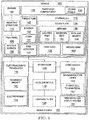
- media system 100 for vehicle 102 having chassis 104 comprises electroacoustic transducer 114, integrated into face panel 108 of stowage bin 110 inside vehicle 102.
- Stowage bin 110 comprises mounting structure 112 that is stationary relative to chassis 104 of vehicle 102.
- Interior 130 of stowage bin 110 is accessible via face panel 108.
- Face panel 108 is movably coupled to mounting structure 112.
- media system 100 that includes electroacoustic transducer 114, as set forth above, enables positioning electroacoustic transducer 114 in face panel 108 of stowage bin 110 inside vehicle 102, such as an airplane. Positioning electroacoustic transducer 114 in face panel 108 of stowage bin 110 enables other surfaces inside vehicle 102 to be utilized for other functionalities. Face panel 108 is movably coupled to mounting structure 112 and provides access to interior 130 of stowage bin 110.
- electroacoustic transducer 114 integrated in face panel 108 allows surfaces previously utilized for flat-panel speaker technology to be repurposed for other functions, such as providing a high-definition display inside vehicle 102.
- media system 100 allows face panel 108 of stowage bin 110 to function as a flat-panel speaker while also providing access to interior 130 of stowage bin 110.
- face panel 108 of stowage bin 110 is capable of being moved between, inclusively, a first position relative to mounting structure 112 of stowage bin 110 and a second position relative to mounting structure 112.
- Allowing face panel 108 of stowage bin 110 to move between a first position relative to mounting structure 112 of stowage bin and second position relative to mounting structure 112 allows face panel 108 of stowage bin 110 to function as a flat-panel speaker while also providing access to interior 130 of stowage bin 110.
- media system 100 further comprises attenuator 126, operatively coupled to electroacoustic transducer 114.
- Media system 100 also comprises audio source 124, operatively coupled to attenuator 126.
- Media system 100 additionally comprises accelerometer 116, integrated into face panel 108 of stowage bin 110 and operatively coupled to attenuator 126.
- Audio source 124 is configured to provide a first electrical signal to attenuator 126.
- Attenuator 126 is configured to provide a second electrical signal to electroacoustic transducer 114.
- media system 100 including attenuator 126 allows for a second electrical signal, that may be different from a first electrical signal provided by audio source 124 to attenuator 126, to be provided to electroacoustic transducer 114.
- a second electrical signal that may be different from a first electrical signal provided by audio source 124 to attenuator 126
- attenuator 126 provides a second electrical signal to electroacoustic transducer 114.
- Use of attenuator 126 allows attenuated electrical signals, different from the first electrical signal sent from audio source 124, to drive electroacoustic transducer 114.
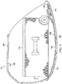
- Accelerometer 116 is integrated into face panel 108 of stowage bin 110 and operatively coupled to attenuator 126. When coupled with attenuator 126, accelerometer 116 allows attenuated electrical signals to drive electroacoustic transducer 114 based on output from accelerometer 116 to attenuator 126.
- accelerometer 116 is configured to generate output responsive to a location of face panel 108 of stowage bin 110 between, inclusively, the first position of face panel 108 relative to mounting structure 112 and the second position of face panel 108 relative to mounting structure 112.
- Attenuator 126 can provide an electrical signal to electroacoustic transducer 114 based on a location of face panel 108 relative to mounting structure 112.
- accelerometer 116 allows different electrical signals to drive electroacoustic transducer 114 based a location of face panel 108 relative to mounting structure 112.
- accelerometer 116 may be a multiaxis accelerometer, capable of measuring acceleration in multiple directions. In this manner, accelerometer 116 detects acceleration as a vector quantity, and can be used to sense orientation of accelerometer 116.
- accelerometer 116 allows for the determination of a position of face panel 108, including, inclusively, the first position of face panel 108 relative to mounting structure 112 and the second position of face panel 108 relative to mounting structure 112.
- Attenuator 126 when face panel 108 is in the first position relative to mounting structure 112, attenuator 126 provides electroacoustic transducer 114 with the second electrical signal that is not attenuated relative to the first electrical signal, communicated from audio source 124 to attenuator 126, based on the location of face panel 108 relative to mounting structure 112.
- Attenuator 126 When face panel 108 is in the second position relative to mounting structure 112, attenuator 126 provides electroacoustic transducer 114 with the second electrical signal that is attenuated relative to the first electrical signal, communicated from audio source 124 to attenuator 126, at least based on the location of face panel 108 relative to mounting structure 112.
- accelerometer 116 integrated into face panel 108 of stowage bin 110 allows attenuator 126 to provide different electrical signals based on position of face panel 108 relative to mounting structure 112.
- attenuator 126 when face panel 108 is in the first position relative to mounting structure 112, attenuator 126 provides an electrical signal that is not attenuated relative to the first electrical signal from audio source 124 based on the location of face panel 108.
- face panel 108 when face panel 108 is in the second position relative to mounting structure 112, attenuator 126 provides an electrical signal that is attenuated relative to the first signal from audio source 124 based on the location of face panel 108.
- accelerometer 116 allows media system 100 to provide attenuated audio to vehicle 102 based on a position of face panel 108 relative to mounting structure 112.
- example 6 responsive to face panel 108 of stowage bin 110 being moved with respect to mounting structure 112 of stowage bin 110 between, exclusively, the first position of face panel 108 relative to mounting structure 112 and, inclusively, the second position of face panel 108 relative to mounting structure 112, the second electrical signal, communicated from attenuator 126 to electroacoustic transducer 114, is linearly attenuated relative to the first electrical signal, communicated from audio source 124 to attenuator 126.
- example 6 also includes the subject matter according to example 5, above.
- Attenuator 126 linearly attenuates the second electrical signal relative to the first electrical signal as face panel 108 of stowage bin 110 is moved between the first position and the second position.
- a linear attenuation of the second electrical signal provides a gradual adjustment to the attenuation of the electrical signal as face panel 108 of stowage bin 110 is moved between the first position and the second position.
- example 7 of the present disclosure, wherein example 7 also includes the subject matter according to example 5, above.
- Attenuator 126 non-linearly attenuates the second electrical signal relative to the first electrical signal as face panel 108 of stowage bin 110 is moved between the first position and the second position.
- a non-linear attenuation of the second electrical signal provides a gradual adjustment to the attenuation of the electrical signal as face panel 108 of stowage bin 110 is moved between the first position and the second position.
- electroacoustic transducer 114 is configured to excite face panel 108 of stowage bin 110 based on the second electrical signal, communicated from attenuator 126 to electroacoustic transducer 114.
- the preceding subject matter of this paragraph characterizes example 8 of the present disclosure, wherein example 8 also includes the subject matter according to any one of examples 5 to 7, above. Exciting face panel 108 of stowage bin 110 based on the second electrical signal provides for selective excitement of face panel 108 by electroacoustic transducer 114 relative to the electrical signal received from attenuator 126.
- a media system such as media system 100, can provide different excitation of face panel 108 of stowage bin 110 based on the position of face panel 108.
- electroacoustic transducer 114 can selectively excite face panel 108 according to a second electrical signal when face panel 108 is in second position relative to mounting structure 112.
- face panel 108 of stowage bin 110 is configured to retain items 131 within interior 130 of stowage bin 110 when face panel 108 is in the first position. Face panel 108 is configured to provide access to interior 130 of stowage bin 110 when face panel 108 is in the second position.
- face panel 108 of stowage bin 110 When in the first position, face panel 108 of stowage bin 110 is configured to retain items 131 within interior 130 of stowage bin 110. When in the second position, face panel 108 of stowage bin 110 is configured to provide access to interior 130 of stowage bin 110. Allowing face panel 108 of stowage bin 110 to move between a first position relative to mounting structure 112 of stowage bin and second position relative to mounting structure 112 allows face panel 108 of stowage bin 110 to function as a flat-panel speaker while also providing access to interior 130 of stowage bin 110.
- Electroacoustic transducer 114 integrated in face panel 108 of stowage bin 110 while retaining the item-securing functionality of face panel 108 of retaining items within stowage bin 110 when face panel 108 is moved between a first position relative to mounting structure 112 of stowage bin and second position relative to mounting structure 112.
- stowage bin 110 further comprises item detector 132, operatively coupled to attenuator 126.
- Item detector 132 is configured to provide an input to attenuator 126, indicating whether items 131 are present within interior 130 of stowage bin 110.
- Item detectors such as item detector 132 may be incorporated into stowage bin 110.
- Item detector 132 indicates to attenuator 126 whether items 131 are present within interior 130 of stowage and 110.
- attenuator 126 can provide an electrical signal to electroacoustic transducer 114 based on the presence of items 131 within interior 130 of stowage bin 110.
- item detector 132 allows different electrical signals to drive electroacoustic transducer 114 based the presence of items 131 within interior 130 of stowage bin 110.
- the input from item detector 132 causes attenuator 126 to provide electroacoustic transducer 114 with the second electrical signal that is not attenuated, at least based on the input from item detector 132 to attenuator 126, relative to the first electrical signal, communicated from audio source 124 to attenuator 126.
- Attenuator 126 When items 131 are absent from interior 130 of stowage bin 110, attenuator 126 provides electroacoustic transducer 114 with the second electrical signal that is attenuated, based on the input from item detector 132 to attenuator 126, relative to the first electrical signal, communicated from audio source 124 to attenuator 126.
- Attenuator 126 uses item detector 132 in stowage bin 110 to provide different electrical signals based on the presence of items 131 within interior 130 of stowage bin 110.
- attenuator 126 provides an electrical signal that is attenuated relative to the first electrical signal from audio source 124 based on the location of face panel 108.
- attenuator 126 provides an electrical signal that is not attenuated relative to the first signal from audio source 124 based on the location of face panel 108.
- accelerometer 116 allows media system 100 to provide attenuated audio to vehicle 102 based on a position of face panel 108 relative to mounting structure 112.
- media system 100 further comprises low-pass filter 128, operatively coupled to accelerometer 116.
- Low-pass filter 128 is configured to adjust the output of accelerometer 116 based on acceleration of vehicle 102.
- low-pass filter 128 When operatively coupled to accelerometer 116, low-pass filter 128 allows media system 100 to adjust the output of accelerometer 116 based on acceleration of vehicle 102. In this manner, low-pass filter 128 prevents inadvertent attenuation or non-attenuation of the first electrical signal based due to accelerometer 116 detecting acceleration of vehicle 102.
- cover plate 134 is secured to interior surface 135 of face panel 108 of stowage bin 110.
- Torque tube 140 is retained between cover plate 134 and face panel 108.
- Electroacoustic transducer 114 is retained between cover plate 134 and face panel 108.
- Torque tube 140 is retained between cover plate 134 and face panel 108, and is provided to secure face panel 108 in first position relative to mounting structure 112.
- Cover plate 134 is secured to interior surface 135 of face panel 108 of stowage bin 110.
- cover plate 134 further comprises retainer 138.
- Retainer 138 is configured to locate electroacoustic transducer 114 along cover plate 134.
- cover plate 134 includes retainer 138
- electroacoustic transducer 114 can be easily located along cover plate 134 in a position selected to provide a desired level of acoustic performance when exciting face panel 108.
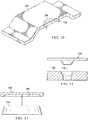
- retainer 138 comprises one of locating post 152, recessed seat 154, resilient finger 156, or any combination thereof.
- electroacoustic transducer 114 can be easily located along cover plate 134 in a position selected to provide a desired level of acoustic performance when exciting face panel 108.
- electroacoustic transducer 114 further comprises permanent magnet 142, located relative to cover plate 134 by retainer 138. Additionally, electroacoustic transducer 114 comprises electromagnet 144, connected to interior surface 135 of face panel 108 and in contact with permanent magnet 142.
- electroacoustic transducer 114 comprises permanent magnet 142, located relative to cover plate 134 by retainer 138 and electromagnet 144, connected to interior surface 135 of face panel 108 and in contact with permanent magnet 142.
- Permanent magnet 142 located relative to cover plate 134 and electromagnet 144, connected to interior surface 135 of face panel 108, allows electroacoustic transducer 114 to provide a desired level of acoustic performance when exciting face panel 108.
- electromagnet 144 is a voice coil wire.
- the preceding subject matter of this paragraph characterizes example 17 of the present disclosure, wherein example 17 also includes the subject matter according to example 16, above.
- electromagnet 144 is a voice coil wire.
- electroacoustic transducer 114 provides a desired level of acoustic performance when exciting face panel 108.
- electromagnet 144 is connected to interior surface 135 of face panel 108 using a flexible adhesive.
- electroacoustic transducer 114 When electromagnet 144 is connected to interior surface 135 of face panel 108 using a flexible adhesive, electroacoustic transducer 114 can be easily secured to interior surface 135 of face panel 108 in a position selected to provide a desired level of acoustic performance when exciting face panel 108.
- cover plate 134 further comprises first area 158, proximately located to electroacoustic transducer 114.
- First area 158 has a first locally tailored physical characteristic selected to provide an acoustic property.
- cover plate 134 comprises second area 160, distally located from electroacoustic transducer 114.
- a second physical characteristic of second area 160 is different from the first locally tailored physical characteristic of first area 158.
- each area can be specifically designed to impart desired physical properties that may be more pertinent to that particular area.
- cover plate 134 further comprises first area 158 proximately located to electroacoustic transducer 114
- a first physical characteristic of first area 158 may be locally tailored to provide an acoustic property.
- second area 160 of cover plate 134 distally located from electroacoustic transducer 114, may have a second physical characteristic that different from the first locally tailored physical characteristic of first area 158.
- first area 158 may have a first physical characteristic, such as a stiffness, designed to optimize acoustic performance of electroacoustic transducer 114.
- Second area 160 may have a second physical characteristic, such as a stiffness, designed to optimize impact resistance or durability of cover plate 134.
- media system 100 further comprises sound-insulation layer 146, positioned over at least a portion of cover plate 134 to acoustically isolate electroacoustic transducer 114 from interior 130 of stowage bin 110.
- sound-insulation layer 146 positioned over at least a portion of cover plate 134 to acoustically isolate electroacoustic transducer 114 from interior 130 of stowage bin 110.
- electroacoustic transducer 114 can be acoustically isolated from interior 130 of stowage bin 110 to provide a desired level of acoustic performance when exciting face panel 108.
- sound-insulation layer 146 comprises closed-cell foam material 162.
- sound-insulation layer 146 comprises closed-cell foam material 162
- electroacoustic transducer 114 can be acoustically isolated from interior 130 of stowage bin 110 to provide a desired level of acoustic performance when exciting face panel 108.
- closed-cell foam material 162 is a viscoelastic polyurethane foam.
- media system 100 further comprises high-definition display system 122, integrated into ceiling panels 120 of passenger compartment 118 of vehicle 102.
- High-definition display system 122 is operatively coupled with audio source 124.
- media system 100 including electroacoustic transducer 114 as set forth above, allows for positioning of electroacoustic transducer 114 in face panel 108 of stowage bin 110 inside vehicle 102, such as an airplane.
- electroacoustic transducer 114 By positioning electroacoustic transducer 114 in face panel 108 of stowage bin 110, media system 100 allows other surfaces inside vehicle 102, such as ceiling panels 120 of passenger compartment 118 of vehicle 102, to be utilized for other functionalities, such as high-definition display system 122, integrated into ceiling panels 120 of passenger compartment 118.
- electroacoustic transducer 114 integrated in face panel 108 allows ceiling panels 120 of passenger compartment 118 of vehicle 102, previously utilized for flat-panel speaker technology, to be repurposed for other high-definition display system 122, integrated into ceiling panels 120 of passenger compartment 118.
- media system 100 allows face panel 108 of stowage bin 110 to function as a flat-panel speaker while also allowing the integration of high-definition display system 122 into ceiling panels 120 of passenger compartment 118.
- Vehicle 102 comprises chassis 104 and passenger compartment 118. Passenger compartment 118 comprises ceiling panels 120. Vehicle 102 additionally comprises stowage bin 110 in passenger compartment 118. Stowage bin 110 comprises mounting structure 112 that is stationary relative to chassis 104. Stowage bin 110 also comprises face panel 108, movably coupled to mounting structure 112. Additionally, stowage bin 110 comprises interior 130, accessible via face panel 108. Vehicle 102 further comprises media system 100. Media system 100 comprises high-definition display system 122, integrated into ceiling panels 120. Media system 100 also comprises audio source 124, operatively coupled with high-definition display system 122. Media system 100 additionally comprises electroacoustic transducer 114, integrated into face panel 108 of stowage bin 110.
- the preceding subject matter of this paragraph characterizes example 23 of the present disclosure.
- media system 100 that includes electroacoustic transducer 114 as set forth above, in vehicle 102, such as an airplane, enables positioning electroacoustic transducer 114 in face panel 108 of stowage bin 110 inside vehicle 102.
- Positioning electroacoustic transducer 114 in face panel 108 of stowage bin 110 enables other surfaces inside vehicle 102, such as ceiling panels 120 of passenger compartment 118 of vehicle 102, to be utilized for other functionalities, such as high-definition display system 122, integrated into ceiling panels 120 of passenger compartment 118.
- electroacoustic transducer 114 integrated in face panel 108 enables ceiling panels 120 of passenger compartment 118 of vehicle 102, previously utilized for flat-panel speaker technology, to be repurposed for other high-definition display system 122, integrated into ceiling panels 120 of passenger compartment 118.
- media system 100 enables face panel 108 of stowage bin 110 to function as a flat-panel speaker while also enabling the integration of high-definition display system 122 into ceiling panels 120 of passenger compartment 118.
- face panel 108 of stowage bin 110 is capable of being moved between, inclusively, a first position relative to mounting structure 112 of stowage bin 110 and a second position relative to mounting structure 112.
- Allowing face panel 108 of stowage bin 110 to move between a first position relative to mounting structure 112 of stowage bin and second position relative to mounting structure 112 allows face panel 108 of stowage bin 110 to function as a flat-panel speaker while also providing access to interior 130 of stowage bin 110.
- media system 100 of vehicle 102 further comprises attenuator 126, operatively coupled to electroacoustic transducer 114, and accelerometer 116, integrated into face panel 108 of stowage bin 110 and operatively coupled to attenuator 126.
- Audio source 124 is configured to provide a first electrical signal to attenuator 126.
- Attenuator 126 is configured to provide a second electrical signal to electroacoustic transducer 114.
- Use of media system 100 including attenuator 126, in vehicle 102 allows for a second electrical signal, that may be different from a first electrical signal provided by audio source 124 to attenuator 126, to be provided to electroacoustic transducer 114.
- a second electrical signal that may be different from a first electrical signal provided by audio source 124 to attenuator 126
- attenuator 126 provides a second electrical signal to electroacoustic transducer 114.
- Use of attenuator 126 allows attenuated electrical signals, different from the first electrical signal sent from audio source 124, to drive electroacoustic transducer 114.
- Accelerometer 116 is integrated into face panel 108 of stowage bin 110 and operatively coupled to attenuator 126. When coupled with attenuator 126, accelerometer 116 allows attenuated electrical signals to drive electroacoustic transducer 114 based on output from accelerometer 116 to attenuator 126.
- accelerometer 116 is configured to generate output responsive to a location of face panel 108 of stowage bin 110 between, inclusively, the first position of face panel 108 relative to mounting structure 112 and the second position of face panel 108 relative to mounting structure 112.
- Attenuator 126 can provide an electrical signal to electroacoustic transducer 114 based on a location of face panel 108 relative to mounting structure 112.
- accelerometer 116 allows different electrical signals to drive electroacoustic transducer 114 based a location of face panel 108 relative to mounting structure 112.
- accelerometer 116 may be a multiaxis accelerometer, capable of measuring acceleration in multiple directions. In this manner, accelerometer 116 detects acceleration as a vector quantity, and can be used to sense orientation of accelerometer 116.
- accelerometer 116 allows for the determination of a position of face panel 108, including, inclusively, the first position of face panel 108 relative to mounting structure 112 and the second position of face panel 108 relative to mounting structure 112.
- Attenuator 126 when face panel 108 is in the first position relative to mounting structure 112, attenuator 126 provides electroacoustic transducer 114 with the second electrical signal that is not attenuated relative to the first electrical signal, communicated from audio source 124 to attenuator 126, based on the location of face panel 108 relative to mounting structure 112.
- attenuator 126 provides electroacoustic transducer 114 with the second electrical signal that is attenuated relative to the first electrical signal, communicated from audio source 124 to attenuator 126, based on the location of face panel 108 relative to mounting structure 112.
- accelerometer 116 integrated into face panel 108 of stowage bin 110 allows attenuator 126 to provide different electrical signals based on position of face panel 108 relative to mounting structure 112.
- attenuator 126 when face panel 108 is in the first position relative to mounting structure 112, attenuator 126 provides an electrical signal that is not attenuated relative to the first electrical signal from audio source 124 based on the location of face panel 108.
- face panel 108 when face panel 108 is in the second position relative to mounting structure 112, attenuator 126 provides an electrical signal that is attenuated relative to the first signal from audio source 124 based on the location of face panel 108.
- accelerometer 116 allows media system 100 to provide attenuated audio to vehicle 102 based on a position of face panel 108 relative to mounting structure 112.
- example 28 of the present disclosure responsive to face panel 108 of stowage bin 110 being moved with respect to mounting structure 112 of stowage bin 110 between, exclusively, the first position of face panel 108 relative to mounting structure 112 and, inclusively, the second position of face panel 108 relative to mounting structure 112, the second electrical signal, communicated from attenuator 126 to electroacoustic transducer 114, is linearly attenuated relative to the first electrical signal, communicated from audio source 124 to attenuator 126.
- example 28 also includes the subject matter according to any one of examples 26 to 27, above.
- Attenuator 126 linearly attenuates the second electrical signal relative to the first electrical signal as face panel 108 of stowage bin 110 is moved between the first position and the second position.
- a linear attenuation of the second electrical signal provides a gradual adjustment to the attenuation of the electrical signal as face panel 108 of stowage bin 110 is moved between the first position and the second position.
- the second electrical signal communicated from attenuator 126 to electroacoustic transducer 114, is non-linearly attenuated relative to the first electrical signal, communicated from audio source 124 to attenuator 126.
- example 29 also includes the subject matter according to any one of examples 26 to 27, above.
- attenuator 126 non-linearly attenuates the second electrical signal relative to the first electrical signal as face panel 108 of stowage bin 110 is moved between the first position and the second position.
- a non-linear attenuation of the second electrical signal provides a gradual adjustment to the attenuation of the electrical signal as face panel 108 of stowage bin 110 is moved between the first position and the second position.
- electroacoustic transducer 114 is configured to excite face panel 108 of stowage bin 110 based on the second electrical signal, communicated from attenuator 126 to electroacoustic transducer 114.
- Exciting face panel 108 of stowage bin 110 based on the second electrical signal provides for selective excitement of face panel 108 by electroacoustic transducer 114 relative to the electrical signal received from attenuator 126.
- a media system such as media system 100, can provide different excitation of face panel 108 of stowage bin 110 based on the position of face panel 108.
- electroacoustic transducer 114 can selectively excite face panel 108 according to a second electrical signal when face panel 108 is in second position relative to mounting structure 112.
- face panel 108 of stowage bin 110 is configured to retain items 131 within interior 130 of stowage bin 110 when face panel 108 is in the first position. Face panel 108 is configured to provide access to interior 130 of stowage bin 110 when face panel 108 is in the second position.
- face panel 108 of stowage bin 110 When in the first position, face panel 108 of stowage bin 110 is configured to retain items 131 within interior 130 of stowage bin 110. When in the second position, face panel 108 of stowage bin 110 is configured to provide access to interior 130 of stowage bin 110. Allowing face panel 108 of stowage bin 110 to move between a first position relative to mounting structure 112 of stowage bin and second position relative to mounting structure 112 allows face panel 108 of stowage bin 110 to function as a flat-panel speaker while also providing access to interior 130 of stowage bin 110.
- Electroacoustic transducer 114 integrated in face panel 108 of stowage bin 110 while retaining the item-securing functionality of face panel 108 of retaining items within stowage bin 110 when face panel 108 is moved between a first position relative to mounting structure 112 of stowage bin and second position relative to mounting structure 112.
- stowage bin 110 further comprises item detector 132, operatively coupled to attenuator 126.
- Item detector 132 is configured to provide an input to attenuator 126, indicating whether items 131 are present within interior 130 of stowage bin 110.
- Item detectors such as item detector 132 may be incorporated into stowage bin 110.
- Item detector 132 indicates to attenuator 126 whether items 131 are present within interior 130 of stowage and 110.
- attenuator 126 can provide an electrical signal to electroacoustic transducer 114 based on the presence of items 131 within interior 130 of stowage bin 110.
- item detector 132 allows different electrical signals to drive electroacoustic transducer 114 based the presence of items 131 within interior 130 of stowage bin 110.
- the input from item detector 132 causes attenuator 126 to provide electroacoustic transducer 114 with the second electrical signal that is not attenuated, at least based on the input from item detector 132 to attenuator 126, relative to the first electrical signal, communicated from audio source 124 to attenuator 126.
- Attenuator 126 When items 131 are absent from interior 130 of stowage bin 110, attenuator 126 provides electroacoustic transducer 114 with the second electrical signal that is attenuated, based on the input from item detector 132 to attenuator 126, relative to the first electrical signal, communicated from audio source 124 to attenuator 126.
- the preceding subject matter of this paragraph characterizes example 33 of the present disclosure, wherein example 33 also includes the subject matter according to example 32, above.
- Attenuator 126 uses item detector 132 in stowage bin 110 to provide different electrical signals based on the presence of items 131 within interior 130 of stowage bin 110.
- attenuator 126 provides an electrical signal that is attenuated relative to the first electrical signal from audio source 124 based on the location of face panel 108.
- attenuator 126 provides an electrical signal that is attenuated relative to the first signal from audio source 124 based on the location of face panel 108.
- accelerometer 116 allows media system 100 to provide attenuated audio to vehicle 102 based on a position of face panel 108 relative to mounting structure 112.
- vehicle 102 further comprises low-pass filter 128, operatively coupled to accelerometer 116.
- Low-pass filter 128 is configured to adjust the output of accelerometer 116 based on acceleration of vehicle 102.
- low-pass filter 128 When operatively coupled to accelerometer 116, low-pass filter 128 allows media system 100 to adjust the output of accelerometer 116 based on acceleration of vehicle 102. In this manner, low-pass filter 128 prevents inadvertent attenuation or non-attenuation of the first electrical signal based due to accelerometer 116 detecting acceleration of vehicle 102.
- cover plate 134 is secured to interior surface 135 of face panel 108 of stowage bin 110.
- Torque tube 140 is retained between cover plate 134 and face panel 108.
- Electroacoustic transducer 114 is retained between cover plate 134 and face panel 108.
- Torque tube 140 is retained between cover plate 134 and face panel 108, and is provided to secure face panel 108 in first position relative to mounting structure 112.
- Cover plate 134 is secured to interior surface 135 of face panel 108 of stowage bin 110.
- cover plate 134 further comprises retainer 138.
- Retainer 138 is configured to locate electroacoustic transducer 114 along cover plate 134.
- cover plate 134 includes retainer 138
- electroacoustic transducer 114 can be easily located along cover plate 134 in a position selected to provide a desired level of acoustic performance when exciting face panel 108.
- retainer 138 comprises one of locating post 152, recessed seat 154, resilient finger 156, or any combination thereof.
- electroacoustic transducer 114 can be easily located along cover plate 134 in a position selected to provide a desired level of acoustic performance when exciting face panel 108.
- electroacoustic transducer 114 further comprises permanent magnet 142, located relative to cover plate 134 by retainer 138.
- electroacoustic transducer 114 comprises electromagnet 144, connected to interior surface 135 of face panel 108 and in contact with permanent magnet 142.
- electroacoustic transducer 114 comprises permanent magnet 142, located relative to cover plate 134 by retainer 138 and electromagnet 144, connected to interior surface 135 of face panel 108 and in contact with permanent magnet 142.
- Permanent magnet 142 located relative to cover plate 134 and electromagnet 144, connected to interior surface 135 of face panel 108, allows electroacoustic transducer 114 to provide a desired level of acoustic performance when exciting face panel 108.
- electromagnet 144 is a voice coil wire.
- the preceding subject matter of this paragraph characterizes example 39 of the present disclosure, wherein example 39 also includes the subject matter according to example 38, above.
- electromagnet 144 is a voice coil wire.
- electroacoustic transducer 114 provides a desired level of acoustic performance when exciting face panel 108.
- electromagnet 144 is connected to interior surface 135 of face panel 108 using a flexible adhesive.
- electroacoustic transducer 114 When electromagnet 144 is connected to interior surface 135 of face panel 108 using a flexible adhesive, electroacoustic transducer 114 can be easily secured to interior surface 135 of face panel 108 in a position selected to provide a desired level of acoustic performance when exciting face panel 108.
- cover plate 134 further comprises first area 158, proximately located to electroacoustic transducer 114.
- First area 158 has a first locally tailored physical characteristic, selected to provide an acoustic property.
- cover plate 134 comprises second area 160, distally located from electroacoustic transducer 114.
- a second physical characteristic of second area 160 is different from the first locally tailored physical characteristic of first area 158.
- each area can be specifically designed to impart desired physical properties that may be more pertinent to that particular area.
- cover plate 134 further comprises first area 158 proximately located to electroacoustic transducer 114
- a first physical characteristic of first area 158 may be locally tailored to provide an acoustic property.
- second area 160 of cover plate 134 distally located from electroacoustic transducer 114, may have a second physical characteristic that different from the first locally tailored physical characteristic of first area 158.
- first area 158 may have a first physical characteristic, such as a stiffness, designed to optimize acoustic performance of electroacoustic transducer 114.
- Second area 160 may have a second physical characteristic, such as a stiffness, designed to optimize impact resistance or durability of cover plate 134.
- vehicle 102 further comprises sound-insulation layer 146, positioned over at least a portion of cover plate 134 to acoustically isolate electroacoustic transducer 114 from interior 130 of stowage bin 110.
- sound-insulation layer 146 positioned over at least a portion of cover plate 134 to acoustically isolate electroacoustic transducer 114 from interior 130 of stowage bin 110.
- electroacoustic transducer 114 can be acoustically isolated electroacoustic transducer 114 from interior 130 of stowage bin 110 to provide a desired level of acoustic performance when exciting face panel 108.
- sound-insulation layer 146 comprises closed-cell foam material 162.
- electroacoustic transducer 114 can be acoustically isolated electroacoustic transducer 114 from interior 130 of stowage bin 110 to provide a desired level of acoustic performance when exciting face panel 108.
- closed-cell foam material 162 is a viscoelastic polyurethane foam.
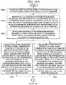
- Method 1400 comprises (block 1402 ) exciting face panel 108 with electroacoustic transducer 114, integrated into face panel 108 of stowage bin 110.
- Stowage bin 110 further comprises mounting structure 112 that is stationary relative to chassis 104 of vehicle 102.
- Stowage bin 110 also comprises interior 130, accessible via face panel 108.
- Method 1400 enables acoustic excitation of face panel 108 of stowage bin 110 via electroacoustic transducer 114, positioned therein.
- Implementing method 1500 enables utilization of other surfaces inside vehicle 102 for other functionalities.
- Face panel 108 is movably coupled to mounting structure 112, allowing for access to interior 130 of stowage bin 110.
- electroacoustic transducer 114 integrated in face panel 108 allows surfaces previously utilized for flat-panel speaker technology to be repurposed for other functions, such as providing a high-definition display inside vehicle 102.
- media system 100 allows face panel 108 of stowage bin 110 to function as a flat-panel speaker while also providing access to interior 130 of stowage bin 110
- method 1400 further comprises (block 1404 ) moving face panel 108 of stowage bin 110 between, inclusively, a first position relative to mounting structure 112 of stowage bin 110 and a second position relative to mounting structure 112.
- block 1404 moving face panel 108 of stowage bin 110 between, inclusively, a first position relative to mounting structure 112 of stowage bin 110 and a second position relative to mounting structure 112.
- face panel 108 of stowage bin 110 When in the first position, face panel 108 of stowage bin 110 is configured to retain items 131 within interior 130 of stowage bin 110. When in the second position, face panel 108 of stowage bin 110 is configured to provide access to interior 130 of stowage bin 110. Allowing face panel 108 of stowage bin 110 to move between a first position relative to mounting structure 112 of stowage bin and second position relative to mounting structure 112 allows face panel 108 of stowage bin 110 to function as a flat-panel speaker while also providing access to interior 130 of stowage bin 110.
- Electroacoustic transducer 114 integrated in face panel 108 of stowage bin 110 allows face panel 108 to retain the item-securing functionality of stowage bin 110 when face panel 108 is moved between a first position relative to mounting structure 112 of stowage bin and second position relative to mounting structure 112.
- method 1400 further comprises (block 1406 ) providing a first electrical signal to attenuator 126 from audio source 124, operatively coupled to attenuator 126.
- Method 1500 also comprises (block 1408 ) providing a second electrical signal to electroacoustic transducer 114 from attenuator 126, operatively coupled to electroacoustic transducer 114.
- media system 100 including attenuator 126 allows for a second electrical signal, that may be different from a first electrical signal provided by audio source 124 to attenuator 126, to be provided to electroacoustic transducer 114.
- a second electrical signal that may be different from a first electrical signal provided by audio source 124 to attenuator 126
- attenuator 126 provides a second electrical signal to electroacoustic transducer 114.
- Use of attenuator 126 allows attenuated electrical signals, different from the first electrical signal sent from audio source 124, to drive electroacoustic transducer 114.
- Accelerometer 116 is integrated into face panel 108 of stowage bin 110 and operatively coupled to attenuator 126. When coupled with attenuator 126, accelerometer 116 allows attenuated electrical signals to drive electroacoustic transducer 114 based on output from accelerometer 116 to attenuator 126.
- method 1400 further comprises (block 1410 ) responsive to a location of face panel 108 between, inclusively, the first position of face panel 108 relative to mounting structure 112 and the second position of face panel 108 relative to mounting structure 112, generating output by accelerometer 116, integrated into face panel 108 of stowage bin 110 and operatively coupled to attenuator 126.
- block 1410 responsive to a location of face panel 108 between, inclusively, the first position of face panel 108 relative to mounting structure 112 and the second position of face panel 108 relative to mounting structure 112, generating output by accelerometer 116, integrated into face panel 108 of stowage bin 110 and operatively coupled to attenuator 126.
- Attenuator 126 can provide an electrical signal to electroacoustic transducer 114 based on a location of face panel 108 relative to mounting structure 112.
- accelerometer 116 allows different electrical signals to drive electroacoustic transducer 114 based a location of face panel 108 relative to mounting structure 112.
- accelerometer 116 may be a multiaxis accelerometer, capable of measuring acceleration in multiple directions. In this manner, accelerometer 116 detects acceleration as a vector quantity, and can be used to sense orientation of accelerometer 116.
- accelerometer 116 allows for the determination of a position of face panel 108, including, inclusively, the first position of face panel 108 relative to mounting structure 112 and the second position of face panel 108 relative to mounting structure 112.
- providing the second electrical signal to electroacoustic transducer 114 from attenuator 126, operatively coupled to electroacoustic transducer 114 comprises, (block 1412 ) when face panel 108 is in the first position relative to mounting structure 112, providing electroacoustic transducer 114 with the second electrical signal that is not attenuated relative to the first electrical signal based on the location of face panel 108 relative to mounting structure 112.
- Providing the second electrical signal to electroacoustic transducer 114 from attenuator 126 also comprises, (block 1414 ) when face panel 108 is in the second position relative to mounting structure 112, providing electroacoustic transducer 114 with the second electrical signal that is attenuated relative to the first electrical signal based at least on the location of face panel 108 relative to mounting structure 112.
- accelerometer 116 integrated into face panel 108 of stowage bin 110 allows attenuator 126 to provide different electrical signals based on position of face panel 108 relative to mounting structure 112.
- attenuator 126 when face panel 108 is in the first position relative to mounting structure 112, attenuator 126 provides an electrical signal that is not attenuated relative to the first electrical signal from audio source 124 based on the location of face panel 108.
- face panel 108 when face panel 108 is in the second position relative to mounting structure 112, attenuator 126 provides an electrical signal that is attenuated relative to the first signal from audio source 124 based on the location of face panel 108.
- accelerometer 116 allows media system 100 to provide attenuated audio to vehicle 102 based on a position of face panel 108 relative to mounting structure 112.
- method 1400 further comprises (block 1416 ) linearly attenuating the second electrical signal, communicated from attenuator 126 to electroacoustic transducer 114, relative to the first electrical signal, communicated from audio source 124 to attenuator 126, as face panel 108 of stowage bin 110 is moved with respect to mounting structure 112 of stowage bin 110 between, exclusively, the first position of face panel 108 relative to mounting structure 112 and, inclusively, the second position of face panel 108 relative to mounting structure 112.
- Attenuator 126 linearly attenuates the second electrical signal relative to the first electrical signal as face panel 108 of stowage bin 110 is moved between the first position and the second position.
- a linear attenuation of the second electrical signal provides a gradual adjustment to the attenuation of the electrical signal as face panel 108 of stowage bin 110 is moved between the first position and the second position.
- method 1400 further comprises (block 1418 ) non-linearly attenuating the second electrical signal, communicated from attenuator 126 to electroacoustic transducer 114, relative to the first electrical signal, communicated from audio source 124 to attenuator 126, as face panel 108 of stowage bin 110 is moved with respect to mounting structure 112 of stowage bin 110 between, exclusively, the first position of face panel 108 relative to mounting structure 112 and, inclusively, the second position of face panel 108 relative to mounting structure 112.
- example 50 also includes the subject matter according to example 48, above.
- exciting face panel 108 according to block 1402 of method 1400 further comprises (block 1420 ) using electroacoustic transducer 114 to excite face panel 108 based on the second electrical signal, communicated from attenuator 126 to electroacoustic transducer 114.
- Face panel 108 is configured to retain items 131 within interior 130 of stowage bin 110 when face panel 108 of stowage bin 110 is in the first position relative to mounting structure 112.
- Face panel 108 is configured to provide access to interior 130 of stowage bin 110 when face panel 108 is in the second position relative to mounting structure 112.
- Attenuator 126 non-linearly attenuates the second electrical signal relative to the first electrical signal as face panel 108 of stowage bin 110 is moved between the first position and the second position.
- a non-linear attenuation of the second electrical signal provides a gradual adjustment to the attenuation of the electrical signal as face panel 108 of stowage bin 110 is moved between the first position and the second position.
- method 1400 further comprises (block 1422 ) providing an input to attenuator 126 from item detector 132, operatively coupled to attenuator 126, indicating whether items 131 are present within interior 130 of stowage bin 110.
- block 1422 provides an input to attenuator 126 from item detector 132, operatively coupled to attenuator 126, indicating whether items 131 are present within interior 130 of stowage bin 110.
- a media system such as media system 100, can provide different excitation of face panel 108 of stowage bin 110 based on the position of face panel 108.
- electroacoustic transducer 114 can selectively excite face panel 108 according to a second electrical signal when face panel 108 is in second position relative to mounting structure 112.
- the second electrical signal is communicated from attenuator 126 to electroacoustic transducer 114.
- example 53 when items 131 are absent from interior 130 of stowage bin 110, the second electrical signal, attenuated relative to the first electrical signal based on items 131 being present within interior 130 of stowage bin 110, is communicated from attenuator 126 to electroacoustic transducer 114.
- Item detectors such as item detector 132 may be incorporated into stowage bin 110.
- Item detector 132 indicates to attenuator 126 whether items 131 are present within interior 130 of stowage and 110.
- attenuator 126 can provide an electrical signal to electroacoustic transducer 114 based on the presence of items 131 within interior 130 of stowage bin 110.
- item detector 132 allows different electrical signals to drive electroacoustic transducer 114 based the presence of items 131 within interior 130 of stowage bin 110.
- method 1400 further comprises (block 1428 ) adjusting the output of accelerometer 116 with low-pass filter 128, operatively coupled to accelerometer 116.
- Low-pass filter 128 is configured to adjust the output of accelerometer 116 based on acceleration of vehicle 102.
- low-pass filter 128 When operatively coupled to accelerometer 116, low-pass filter 128 allows media system 100 to adjust the output of accelerometer 116 based on acceleration of vehicle 102. In this manner, low-pass filter 128 prevents inadvertent attenuation or non-attenuation of the first electrical signal based due to accelerometer 116 detecting acceleration of vehicle 102.
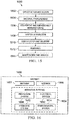
- illustrative method 1500 may include specification and design block 1502 of aircraft 1600 and material procurement block 1504.
- component and subassembly manufacturing block 1506 and system integration block 1508 of aircraft 1600 may take place.
- aircraft 1600 may go through certification and delivery block 1510 to be placed in in service block 1512.
- aircraft 1600 may be scheduled for routine maintenance and service block 1514.
- Routine maintenance and service may include modification, reconfiguration, refurbishment, etc. of one or more systems of aircraft 1600.
- Each of the processes of illustrative method 1500 may be performed or carried out by a system integrator, a third party, and/or an operator e.g., a customer.
- a system integrator may include, without limitation, any number of aircraft manufacturers and major-system subcontractors
- a third party may include, without limitation, any number of vendors, subcontractors, and suppliers
- an operator may be an airline, leasing company, military entity, service organization, and so on.
- aircraft 1600 produced by illustrative method 1500 of FIG. 15 may include airframe 1602 with a plurality of high-level systems 1604 and interior 1606.
- high-level systems 1604 include one or more of propulsion system 1608, electrical system 1610, hydraulic system 1612, and environmental system 1614. Any number of other systems may be included.
- propulsion system 16008 electrical system 1610
- hydraulic system 1612 hydraulic system 1612
- environmental system 1614 any number of other systems may be included.
- Any number of other systems may be included.
- an aerospace example is shown, the principles disclosed herein may be applied to other industries, such as the automotive industry. Accordingly, in addition to aircraft 1600, the principles disclosed herein may apply to other vehicles, e.g., land vehicles, marine vehicles, space vehicles, etc.
- Apparatuses and methods shown or described herein may be employed during any one or more of the stages of the manufacturing and service method 1500.
- components or subassemblies corresponding to component and subassembly manufacturing block 1506 may be fabricated or manufactured in a manner similar to components or subassemblies produced while aircraft 1600 is in in service block 1512.
- one or more examples of the apparatuses, methods, or combination thereof may be utilized during production stages 1506 and 1508, for example, by substantially expediting assembly of or reducing the cost of aircraft 1600.
- one or more examples of the apparatus or method realizations, or a combination thereof may be utilized, for example and without limitation, while aircraft 1600 is in in service block 1512 and/or during maintenance and service block 1514.
Landscapes
- Engineering & Computer Science (AREA)
- Physics & Mathematics (AREA)
- Acoustics & Sound (AREA)
- Signal Processing (AREA)
- Mechanical Engineering (AREA)
- Aviation & Aerospace Engineering (AREA)
- Multimedia (AREA)
- Health & Medical Sciences (AREA)
- Otolaryngology (AREA)
- Fittings On The Vehicle Exterior For Carrying Loads, And Devices For Holding Or Mounting Articles (AREA)
Abstract
Description
- The present disclosure relates to media systems for vehicles.
- Flat panel speaker technology is often used to provide audio for environments in which a premium is placed on physical space and component weight, such as in an aircraft. However, vibration of surfaces that have been traditionally utilized for flat panel speaker technology often render those surfaces incompatible with the incorporation of other systems that may be sensitive to vibration.
- Accordingly, apparatuses and methods, intended to address at least the above-identified concerns, would find utility.
- The following is a non-exhaustive list of examples, which may or may not be claimed, of the subject matter according to the invention.
- One example of the subject matter according to the invention relates to a media system for a vehicle having a chassis. The media system comprises an electroacoustic transducer, integrated into a face panel of a stowage bin inside the vehicle. The stowage bin comprises a mounting structure that is stationary relative to the chassis of the vehicle. An interior of the stowage bin is accessible via the face panel. The face panel is movably coupled to the mounting structure.
- Use of the media system that includes the electroacoustic transducer, as set forth above, enables positioning the electroacoustic transducer in the face panel of the stowage bin inside a vehicle, such as an airplane. Positioning the electroacoustic transducer in the face panel of the stowage bin enables other surfaces inside the vehicle to be utilized for other functionalities. The face panel is movably coupled to the mounting structure and provides access to the interior of the stowage bin. Another example of the subject matter according to the invention relates to a vehicle, comprising a chassis and a passenger compartment. The passenger compartment comprises ceiling panels. The vehicle also comprises a stowage bin in the passenger compartment. The stowage bin comprises a mounting structure that is stationary relative to the chassis. The stowage bin also comprises a face panel, movably coupled to the mounting structure. The stowage bin additionally comprises an interior, accessible via the face panel. The vehicle further comprises a media system. The media system comprises a high-definition display system, integrated into the ceiling panels. The media system also comprises an audio source, operatively coupled with the high-definition display system. The media system additionally comprises an electroacoustic transducer, integrated into the face panel of the stowage bin.
- Use of the media system that includes the electroacoustic transducer, as set forth above, in a vehicle, such as an airplane, enables positioning the electroacoustic transducer in the face panel of the stowage bin inside the vehicle. Positioning the electroacoustic transducer the in face panel of the stowage bin enables other surfaces inside the vehicle, such as the ceiling panels of the passenger compartment of the vehicle, to be utilized for other functionalities, such as the high-definition display system, integrated into the ceiling panels of the passenger compartment.
- Yet another example of the subject matter according to the invention relates to a method of acoustically exciting a face panel of a stowage bin inside a vehicle. The method comprises exciting the face panel with an electroacoustic transducer, integrated into the face panel of the stowage bin. The stowage bin further comprises a mounting structure that is stationary relative to a chassis of the vehicle. The stowage bin also comprises an interior, accessible via the face panel.
- The method enables acoustic excitation of the face panel of the stowage bin via the electroacoustic transducer positioned therein. Implementing the method enables utilization of other surfaces inside the vehicle for other functionalities.
- Having thus described examples of the present disclosure in general terms, reference will now be made to the accompanying drawings, which are not necessarily drawn to scale, and wherein like reference characters designate the same or similar parts throughout the several views, and wherein:
-
FIG. 1 is a block diagram of a vehicle having a media system, according to one or more examples of the present disclosure; -
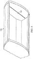
FIG. 2 is a perspective view of a vehicle having a media system, according to one or more examples of the present disclosure; -
FIG. 3 is a cross-sectional view of an electroacoustic transducer, according to one or more examples of the present disclosure; -
FIG. 4 is a cross-sectional view of an electroacoustic transducer integrated into a face panel of a stowage bin inside vehicle, according to one or more examples of the present disclosure; -
FIG. 5 is a perspective view of a mounting structure for a stowage bin, according to one or more examples of the present disclosure; -
FIG. 6 is a perspective view of a stowage bin having a face panel shown in a first position with respect to the mounting structure, according to one or more of the present disclosure; -
FIG. 7 is a perspective view of a stowage bin having a face panel shown in a second position with respect to the mounting structure, according to one or more examples of the present disclosure; -
FIG. 8 is a cross-sectional view of a stowage bin having an accelerometer coupled to the electroacoustic transducer and integrated into a face panel, according to one or more examples of the present disclosure; -
FIG. 9 is a cross-sectional view of a stowage bin having an item therein, according to one or more examples of the present disclosure; -
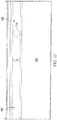
FIG. 10 is a perspective view of a cover plate for a stowage bin having a retainer configured to locate the electroacoustic transducer along the cover plate, according to one or more examples of the present disclosure; -
FIG. 11 is a cross-sectional view of a retainer shown according to an illustrative embodiment and configured to locate the electroacoustic transducer along the cover plate, according to one or more examples of the present disclosure; -
FIG. 12 is a cross-sectional view of a retainer shown according to an illustrative embodiment and configured to locate the electroacoustic transducer along the cover plate, according to one or more examples of the present disclosure; -
FIG. 13 is a perspective view of a cover plate having locally tailored physical characteristics, according to one or more examples of the present disclosure; -
FIGS. 14A ,14B , and14C are a block diagram of a method of utilizing the media system ofFIG. 1 , according to one or more examples of the present disclosure; -
FIG. 15 is a block diagram of aircraft production and service methodology; and -
FIG. 16 is a schematic illustration of an aircraft. - In
FIG. 1 , referred to above, solid lines, if any, connecting various elements and/or components may represent mechanical, electrical, fluid, optical, electromagnetic and other couplings and/or combinations thereof. As used herein, "coupled" means associated directly as well as indirectly. For example, a member A may be directly associated with a member B, or may be indirectly associated therewith, e.g., via another member C. It will be understood that not all relationships among the various disclosed elements are necessarily represented. Accordingly, couplings other than those depicted in the block diagrams may also exist. Dashed lines, if any, connecting blocks designating the various elements and/or components represent couplings similar in function and purpose to those represented by solid lines; however, couplings represented by the dashed lines may either be selectively provided or may relate to alternative examples of the present disclosure. Likewise, elements and/or components, if any, represented with dashed lines, indicate alternative examples of the present disclosure. One or more elements shown in solid and/or dashed lines may be omitted from a particular example without departing from the scope of the present disclosure. Environmental elements, if any, are represented with dotted lines. Virtual imaginary elements may also be shown for clarity. Those skilled in the art will appreciate that some of the features illustrated inFIG. 1 may be combined in various ways without the need to include other features described inFIG. 1 , other drawing figures, and/or the accompanying disclosure, even though such combination or combinations are not explicitly illustrated herein. Similarly, additional features not limited to the examples presented, may be combined with some or all of the features shown and described herein. - In
FIGs. 15 and 16 , referred to above, the blocks may represent operations and/or portions thereof and lines connecting the various blocks do not imply any particular order or dependency of the operations or portions thereof. Blocks represented by dashed lines indicate alternative operations and/or portions thereof. Dashed lines, if any, connecting the various blocks represent alternative dependencies of the operations or portions thereof. It will be understood that not all dependencies among the various disclosed operations are necessarily represented.FIGs. 15 and 16 and the accompanying disclosure describing the operations of the methods set forth herein should not be interpreted as necessarily determining a sequence in which the operations are to be performed. Rather, although one illustrative order is indicated, it is to be understood that the sequence of the operations may be modified when appropriate. Accordingly, certain operations may be performed in a different order or simultaneously. Additionally, those skilled in the art will appreciate that not all operations described need be performed. - In the following description, numerous specific details are set forth to provide a thorough understanding of the disclosed concepts, which may be practiced without some or all of these particulars. In other instances, details of known devices and/or processes have been omitted to avoid unnecessarily obscuring the disclosure. While some concepts will be described in conjunction with specific examples, it will be understood that these examples are not intended to be limiting.
- Unless otherwise indicated, the terms "first," "second," etc. are used herein merely as labels, and are not intended to impose ordinal, positional, or hierarchical requirements on the items to which these terms refer. Moreover, reference to, e.g., a "second" item does not require or preclude the existence of, e.g., a "first" or lower-numbered item, and/or, e.g., a "third" or higher-numbered item.
- Reference herein to "one example" means that one or more feature, structure, or characteristic described in connection with the example is included in at least one implementation. The phrase "one example" in various places in the specification may or may not be referring to the same example.
- As used herein, a system, apparatus, structure, article, element, component, or hardware "configured to" perform a specified function is indeed capable of performing the specified function without any alteration, rather than merely having potential to perform the specified function after further modification. In other words, the system, apparatus, structure, article, element, component, or hardware "configured to" perform a specified function is specifically selected, created, implemented, utilized, programmed, and/or designed for the purpose of performing the specified function. As used herein, "configured to" denotes existing characteristics of a system, apparatus, structure, article, element, component, or hardware which enable the system, apparatus, structure, article, element, component, or hardware to perform the specified function without further modification. For purposes of this disclosure, a system, apparatus, structure, article, element, component, or hardware described as being "configured to" perform a particular function may additionally or alternatively be described as being "adapted to" and/or as being "operative to" perform that function.
- Illustrative, non-exhaustive examples, which may or may not be claimed, of the subject matter according the present disclosure are provided below.
- Referring generally to
FIG. 1 and particularly to, e.g.,FIGS. 2-7 ,media system 100 forvehicle 102 havingchassis 104 is disclosed.Media system 100 compriseselectroacoustic transducer 114, integrated intoface panel 108 ofstowage bin 110 insidevehicle 102.Stowage bin 110 comprises mountingstructure 112 that is stationary relative tochassis 104 ofvehicle 102.Interior 130 ofstowage bin 110 is accessible viaface panel 108.Face panel 108 is movably coupled to mountingstructure 112. The preceding subject matter of this paragraph characterizes example 1 of the present disclosure. - Use of
media system 100 that includeselectroacoustic transducer 114, as set forth above, enables positioningelectroacoustic transducer 114 inface panel 108 ofstowage bin 110 insidevehicle 102, such as an airplane. Positioningelectroacoustic transducer 114 inface panel 108 ofstowage bin 110 enables other surfaces insidevehicle 102 to be utilized for other functionalities.Face panel 108 is movably coupled to mountingstructure 112 and provides access tointerior 130 ofstowage bin 110. - For example,
electroacoustic transducer 114 integrated inface panel 108 allows surfaces previously utilized for flat-panel speaker technology to be repurposed for other functions, such as providing a high-definition display insidevehicle 102. By positioningelectroacoustic transducer 114 inface panel 108 ofstowage bin 110,media system 100 allowsface panel 108 ofstowage bin 110 to function as a flat-panel speaker while also providing access tointerior 130 ofstowage bin 110. - Referring generally to
FIG. 1 and particularly to, e.g.,FIGS. 6-7 ,face panel 108 ofstowage bin 110 is capable of being moved between, inclusively, a first position relative to mountingstructure 112 ofstowage bin 110 and a second position relative to mountingstructure 112. The preceding subject matter of this paragraph characterizes example 2 of the present disclosure, wherein example 2 also includes the subject matter according to example 1, above. - Allowing
face panel 108 ofstowage bin 110 to move between a first position relative to mountingstructure 112 of stowage bin and second position relative to mountingstructure 112 allowsface panel 108 ofstowage bin 110 to function as a flat-panel speaker while also providing access tointerior 130 ofstowage bin 110.Electroacoustic transducer 114 integrated inface panel 108 ofstowage bin 110 while retaining the item-securing functionality offace panel 108 of retaining items withinstowage bin 110 whenface panel 108 is moved between a first position relative to mountingstructure 112 of stowage bin and second position relative to mountingstructure 112. Referring generally toFIG. 1 and particularly to, e.g.,FIGS. 3 and8 ,media system 100 further comprisesattenuator 126, operatively coupled toelectroacoustic transducer 114.Media system 100 also comprisesaudio source 124, operatively coupled toattenuator 126.Media system 100 additionally comprisesaccelerometer 116, integrated intoface panel 108 ofstowage bin 110 and operatively coupled toattenuator 126.Audio source 124 is configured to provide a first electrical signal toattenuator 126.Attenuator 126 is configured to provide a second electrical signal toelectroacoustic transducer 114. The preceding subject matter of this paragraph characterizes example 3 of the present disclosure, wherein example 3 also includes the subject matter according to example 2, above. - Use of media systems, such as
media system 100 includingattenuator 126, allows for a second electrical signal, that may be different from a first electrical signal provided byaudio source 124 toattenuator 126, to be provided toelectroacoustic transducer 114. For example, whenaudio source 124 provides a first electrical signal toattenuator 126,attenuator 126 provides a second electrical signal toelectroacoustic transducer 114. Use ofattenuator 126 allows attenuated electrical signals, different from the first electrical signal sent fromaudio source 124, to driveelectroacoustic transducer 114. -
Accelerometer 116 is integrated intoface panel 108 ofstowage bin 110 and operatively coupled toattenuator 126. When coupled withattenuator 126,accelerometer 116 allows attenuated electrical signals to driveelectroacoustic transducer 114 based on output fromaccelerometer 116 toattenuator 126. - Referring generally to
FIG. 1 and particularly to, e.g.,FIGS. 3-4 and 6-8,accelerometer 116 is configured to generate output responsive to a location offace panel 108 ofstowage bin 110 between, inclusively, the first position offace panel 108 relative to mountingstructure 112 and the second position offace panel 108 relative to mountingstructure 112. The preceding subject matter of this paragraph characterizes example 4 of the present disclosure, wherein example 4 also includes the subject matter according to example 3, above. - By configuring
accelerometer 116 to generate output responsive to a location offace panel 108 ofstowage bin 110,attenuator 126 can provide an electrical signal toelectroacoustic transducer 114 based on a location offace panel 108 relative to mountingstructure 112. When coupled withattenuator 126,accelerometer 116 allows different electrical signals to driveelectroacoustic transducer 114 based a location offace panel 108 relative to mountingstructure 112. - In one illustrative example,
accelerometer 116 may be a multiaxis accelerometer, capable of measuring acceleration in multiple directions. In this manner,accelerometer 116 detects acceleration as a vector quantity, and can be used to sense orientation ofaccelerometer 116. When integrated intoface panel 108 ofstowage bin 110,accelerometer 116 allows for the determination of a position offace panel 108, including, inclusively, the first position offace panel 108 relative to mountingstructure 112 and the second position offace panel 108 relative to mountingstructure 112. - Referring generally to
FIG. 1 and particularly to, e.g.,FIGS. 3-4 and 6-8, whenface panel 108 is in the first position relative to mountingstructure 112,attenuator 126 provideselectroacoustic transducer 114 with the second electrical signal that is not attenuated relative to the first electrical signal, communicated fromaudio source 124 toattenuator 126, based on the location offace panel 108 relative to mountingstructure 112. Whenface panel 108 is in the second position relative to mountingstructure 112,attenuator 126 provideselectroacoustic transducer 114 with the second electrical signal that is attenuated relative to the first electrical signal, communicated fromaudio source 124 toattenuator 126, at least based on the location offace panel 108 relative to mountingstructure 112. The preceding subject matter of this paragraph characterizes example 5 of the present disclosure, wherein example 5 also includes the subject matter according to example 4, above. - Use of
accelerometer 116 integrated intoface panel 108 ofstowage bin 110 allowsattenuator 126 to provide different electrical signals based on position offace panel 108 relative to mountingstructure 112. In one illustrative example, whenface panel 108 is in the first position relative to mountingstructure 112,attenuator 126 provides an electrical signal that is not attenuated relative to the first electrical signal fromaudio source 124 based on the location offace panel 108. In another illustrative example, whenface panel 108 is in the second position relative to mountingstructure 112,attenuator 126 provides an electrical signal that is attenuated relative to the first signal fromaudio source 124 based on the location offace panel 108. In this manner,accelerometer 116 allowsmedia system 100 to provide attenuated audio tovehicle 102 based on a position offace panel 108 relative to mountingstructure 112. - Referring generally to
FIG. 1 and particularly to, e.g.,FIGS. 3-4 and 6-8, responsive to facepanel 108 ofstowage bin 110 being moved with respect to mountingstructure 112 ofstowage bin 110 between, exclusively, the first position offace panel 108 relative to mountingstructure 112 and, inclusively, the second position offace panel 108 relative to mountingstructure 112, the second electrical signal, communicated fromattenuator 126 toelectroacoustic transducer 114, is linearly attenuated relative to the first electrical signal, communicated fromaudio source 124 toattenuator 126. The preceding subject matter of this paragraph characterizes example 6 of the present disclosure, wherein example 6 also includes the subject matter according to example 5, above. - In one illustrative example,
attenuator 126 linearly attenuates the second electrical signal relative to the first electrical signal asface panel 108 ofstowage bin 110 is moved between the first position and the second position. A linear attenuation of the second electrical signal provides a gradual adjustment to the attenuation of the electrical signal asface panel 108 ofstowage bin 110 is moved between the first position and the second position. - Referring generally to
FIG. 1 and particularly to, e.g.,FIGS. 3-4 and 6-8, responsive to facepanel 108 ofstowage bin 110 being moved with respect to mountingstructure 112 ofstowage bin 110 between, exclusively, the first position offace panel 108 relative to mountingstructure 112 and, inclusively, the second position offace panel 108 relative to mountingstructure 112, the second electrical signal, communicated fromattenuator 126 toelectroacoustic transducer 114, is non-linearly attenuated relative to the first electrical signal, communicated fromaudio source 124 toattenuator 126. The preceding subject matter of this paragraph characterizes example 7 of the present disclosure, wherein example 7 also includes the subject matter according to example 5, above. - In one illustrative example,
attenuator 126 non-linearly attenuates the second electrical signal relative to the first electrical signal asface panel 108 ofstowage bin 110 is moved between the first position and the second position. A non-linear attenuation of the second electrical signal provides a gradual adjustment to the attenuation of the electrical signal asface panel 108 ofstowage bin 110 is moved between the first position and the second position. - Referring generally to
FIG. 1 and particularly to, e.g.,FIGS. 3-4 and 6-8,electroacoustic transducer 114 is configured to exciteface panel 108 ofstowage bin 110 based on the second electrical signal, communicated fromattenuator 126 toelectroacoustic transducer 114. The preceding subject matter of this paragraph characterizes example 8 of the present disclosure, wherein example 8 also includes the subject matter according to any one of examples 5 to 7, above.Exciting face panel 108 ofstowage bin 110 based on the second electrical signal provides for selective excitement offace panel 108 byelectroacoustic transducer 114 relative to the electrical signal received fromattenuator 126. In this manner, a media system, such asmedia system 100, can provide different excitation offace panel 108 ofstowage bin 110 based on the position offace panel 108. For example,electroacoustic transducer 114 can selectively exciteface panel 108 according to a second electrical signal whenface panel 108 is in second position relative to mountingstructure 112. - Referring generally to
FIG. 1 and particularly to, e.g.,FIGS. 6-9 ,face panel 108 ofstowage bin 110 is configured to retainitems 131 withininterior 130 ofstowage bin 110 whenface panel 108 is in the first position.Face panel 108 is configured to provide access tointerior 130 ofstowage bin 110 whenface panel 108 is in the second position. The preceding subject matter of this paragraph characterizes example 9 of the present disclosure, wherein example 9 also includes the subject matter according to example 8, above. - When in the first position,
face panel 108 ofstowage bin 110 is configured to retainitems 131 withininterior 130 ofstowage bin 110. When in the second position,face panel 108 ofstowage bin 110 is configured to provide access tointerior 130 ofstowage bin 110. Allowingface panel 108 ofstowage bin 110 to move between a first position relative to mountingstructure 112 of stowage bin and second position relative to mountingstructure 112 allowsface panel 108 ofstowage bin 110 to function as a flat-panel speaker while also providing access tointerior 130 ofstowage bin 110.Electroacoustic transducer 114 integrated inface panel 108 ofstowage bin 110 while retaining the item-securing functionality offace panel 108 of retaining items withinstowage bin 110 whenface panel 108 is moved between a first position relative to mountingstructure 112 of stowage bin and second position relative to mountingstructure 112. - Referring generally to
FIG. 1 and particularly to, e.g.,FIGS. 6-9 ,stowage bin 110 further comprisesitem detector 132, operatively coupled toattenuator 126.Item detector 132 is configured to provide an input toattenuator 126, indicating whetheritems 131 are present withininterior 130 ofstowage bin 110. The preceding subject matter of this paragraph characterizes example 10 of the present disclosure, wherein example 10 also includes the subject matter according to example 9, above. - Item detectors, such as
item detector 132, may be incorporated intostowage bin 110.Item detector 132 indicates to attenuator 126 whetheritems 131 are present withininterior 130 of stowage and 110. By configuringitem detector 132 to generate output responsive to the presence ofitems 131 which ininterior 130 ofstowage bin 110,attenuator 126 can provide an electrical signal toelectroacoustic transducer 114 based on the presence ofitems 131 withininterior 130 ofstowage bin 110. When coupled withattenuator 126,item detector 132 allows different electrical signals to driveelectroacoustic transducer 114 based the presence ofitems 131 withininterior 130 ofstowage bin 110. - Referring generally to
FIG. 1 and particularly to, e.g.,FIGS. 3-4 and 6-9, whenitems 131 are present withininterior 130 ofstowage bin 110, the input fromitem detector 132 causes attenuator 126 to provideelectroacoustic transducer 114 with the second electrical signal that is not attenuated, at least based on the input fromitem detector 132 toattenuator 126, relative to the first electrical signal, communicated fromaudio source 124 toattenuator 126. Whenitems 131 are absent frominterior 130 ofstowage bin 110,attenuator 126 provideselectroacoustic transducer 114 with the second electrical signal that is attenuated, based on the input fromitem detector 132 toattenuator 126, relative to the first electrical signal, communicated fromaudio source 124 toattenuator 126. The preceding subject matter of this paragraph characterizes example 11 of the present disclosure, wherein example 11 also includes the subject matter according to example 10, above. - Use of
item detector 132 instowage bin 110 allowsattenuator 126 to provide different electrical signals based on the presence ofitems 131 withininterior 130 ofstowage bin 110. In one illustrative example, whenitems 131 are absent frominterior 130 ofstowage bin 110,attenuator 126 provides an electrical signal that is attenuated relative to the first electrical signal fromaudio source 124 based on the location offace panel 108. In another illustrative example, whenitems 131 are present withininterior 130 ofstowage bin 110,attenuator 126 provides an electrical signal that is not attenuated relative to the first signal fromaudio source 124 based on the location offace panel 108. In this manner,accelerometer 116 allowsmedia system 100 to provide attenuated audio tovehicle 102 based on a position offace panel 108 relative to mountingstructure 112. - Referring generally to
FIG. 1 and particularly to, e.g.,FIGS. 3-4 ,media system 100 further comprises low-pass filter 128, operatively coupled toaccelerometer 116. Low-pass filter 128 is configured to adjust the output ofaccelerometer 116 based on acceleration ofvehicle 102. The preceding subject matter of this paragraph characterizes example 12 of the present disclosure, wherein example 12 also includes the subject matter according to any one of examples 4 to 11, above. - When operatively coupled to
accelerometer 116, low-pass filter 128 allowsmedia system 100 to adjust the output ofaccelerometer 116 based on acceleration ofvehicle 102. In this manner, low-pass filter 128 prevents inadvertent attenuation or non-attenuation of the first electrical signal based due toaccelerometer 116 detecting acceleration ofvehicle 102. - Referring generally to
FIG. 1 and particularly to, e.g.,FIG. 3 ,cover plate 134 is secured tointerior surface 135 offace panel 108 ofstowage bin 110.Torque tube 140 is retained betweencover plate 134 andface panel 108.Electroacoustic transducer 114 is retained betweencover plate 134 andface panel 108. The preceding subject matter of this paragraph characterizes example 13 of the present disclosure, wherein example 13 also includes the subject matter according to any one of examples 1 to 12, above. -
Torque tube 140 is retained betweencover plate 134 andface panel 108, and is provided to secureface panel 108 in first position relative to mountingstructure 112.Cover plate 134 is secured tointerior surface 135 offace panel 108 ofstowage bin 110. By retainingelectroacoustic transducer 114 betweencover plate 134 andface panel 108, existing structures ofstowage bin 110 are used to protect and concealelectroacoustic transducer 114 withinface panel 108 without adding additional parts or weight tovehicle 102. - Referring generally to
FIG. 1 and particularly to, e.g.,FIGS. 3 , and10 -12,cover plate 134 further comprisesretainer 138.Retainer 138 is configured to locateelectroacoustic transducer 114 alongcover plate 134. The preceding subject matter of this paragraph characterizes example 14 of the present disclosure, wherein example 14 also includes the subject matter according to example 13, above. - When
cover plate 134 includesretainer 138,electroacoustic transducer 114 can be easily located alongcover plate 134 in a position selected to provide a desired level of acoustic performance whenexciting face panel 108. - Referring generally to
FIG. 1 and particularly to, e.g.,FIGS. 3 and10 -12,retainer 138 comprises one of locatingpost 152, recessedseat 154,resilient finger 156, or any combination thereof. The preceding subject matter of this paragraph characterizes example 15 of the present disclosure, wherein example 15 also includes the subject matter according to example 14, above. - When
retainer 138 is one of locatingpost 152, recessedseat 154,resilient finger 156, or any combination thereof,electroacoustic transducer 114 can be easily located alongcover plate 134 in a position selected to provide a desired level of acoustic performance whenexciting face panel 108. - Referring generally to
FIG. 1 and particularly to, e.g.,FIG. 3 ,electroacoustic transducer 114 further comprisespermanent magnet 142, located relative to coverplate 134 byretainer 138. Additionally,electroacoustic transducer 114 compriseselectromagnet 144, connected tointerior surface 135 offace panel 108 and in contact withpermanent magnet 142. The preceding subject matter of this paragraph characterizes example 16 of the present disclosure, wherein example 16 also includes the subject matter according to any one of examples 14 to 15, above. - In one illustrative example,
electroacoustic transducer 114 comprisespermanent magnet 142, located relative to coverplate 134 byretainer 138 andelectromagnet 144, connected tointerior surface 135 offace panel 108 and in contact withpermanent magnet 142.Permanent magnet 142, located relative to coverplate 134 andelectromagnet 144, connected tointerior surface 135 offace panel 108, allowselectroacoustic transducer 114 to provide a desired level of acoustic performance whenexciting face panel 108. - Referring generally to
FIG. 1 and particularly to, e.g.,FIG. 3 ,electromagnet 144 is a voice coil wire. The preceding subject matter of this paragraph characterizes example 17 of the present disclosure, wherein example 17 also includes the subject matter according to example 16, above. In one illustrative example,electromagnet 144 is a voice coil wire. Whenelectromagnet 144 is a voice coil,electroacoustic transducer 114 provides a desired level of acoustic performance whenexciting face panel 108. - Referring generally to
FIG. 1 and particularly to, e.g.,FIG. 3 ,electromagnet 144 is connected tointerior surface 135 offace panel 108 using a flexible adhesive. The preceding subject matter of this paragraph characterizes example 18 of the present disclosure, wherein example 18 also includes the subject matter according to any one of examples 16 to 17, above. - When
electromagnet 144 is connected tointerior surface 135 offace panel 108 using a flexible adhesive,electroacoustic transducer 114 can be easily secured tointerior surface 135 offace panel 108 in a position selected to provide a desired level of acoustic performance whenexciting face panel 108. - Referring generally to
FIG. 1 and particularly to, e.g.,FIGS. 3 , and13 ,cover plate 134 further comprisesfirst area 158, proximately located toelectroacoustic transducer 114.First area 158 has a first locally tailored physical characteristic selected to provide an acoustic property. Additionally,cover plate 134 comprisessecond area 160, distally located fromelectroacoustic transducer 114. A second physical characteristic ofsecond area 160 is different from the first locally tailored physical characteristic offirst area 158. The preceding subject matter of this paragraph characterizes example 19 of the present disclosure, wherein example 19 also includes the subject matter according to any one of examples 13 to 18, above. - By tailoring characteristics of different areas of
cover plate 134, each area can be specifically designed to impart desired physical properties that may be more pertinent to that particular area. For example, whencover plate 134 further comprisesfirst area 158 proximately located toelectroacoustic transducer 114, a first physical characteristic offirst area 158 may be locally tailored to provide an acoustic property. Additionally,second area 160 ofcover plate 134, distally located fromelectroacoustic transducer 114, may have a second physical characteristic that different from the first locally tailored physical characteristic offirst area 158. For example,first area 158 may have a first physical characteristic, such as a stiffness, designed to optimize acoustic performance ofelectroacoustic transducer 114.Second area 160 may have a second physical characteristic, such as a stiffness, designed to optimize impact resistance or durability ofcover plate 134. - Referring generally to
FIG. 1 and particularly to, e.g.,FIGS. 3 and9 ,media system 100 further comprises sound-insulation layer 146, positioned over at least a portion ofcover plate 134 to acoustically isolateelectroacoustic transducer 114 frominterior 130 ofstowage bin 110. The preceding subject matter of this paragraph characterizes example 20 of the present disclosure, wherein example 20 also includes the subject matter according to any one of examples 13 to 19, above. - When sound-
insulation layer 146 is positioned over at least a portion ofcover plate 134,electroacoustic transducer 114 can be acoustically isolated frominterior 130 ofstowage bin 110 to provide a desired level of acoustic performance whenexciting face panel 108. - Referring generally to
FIG. 1 and particularly to, e.g.,FIGS. 3 and9 , sound-insulation layer 146 comprises closed-cell foam material 162. The preceding subject matter of this paragraph characterizes example 21 of the present disclosure, wherein example 21 also includes the subject matter according to example 20, above. - When sound-
insulation layer 146 comprises closed-cell foam material 162,electroacoustic transducer 114 can be acoustically isolated frominterior 130 ofstowage bin 110 to provide a desired level of acoustic performance whenexciting face panel 108. In one illustrative example, closed-cell foam material 162 is a viscoelastic polyurethane foam. - Referring generally to
FIG. 1 and particularly to, e.g.,FIG. 2 ,media system 100 further comprises high-definition display system 122, integrated intoceiling panels 120 ofpassenger compartment 118 ofvehicle 102. High-definition display system 122 is operatively coupled withaudio source 124. The preceding subject matter of this paragraph characterizes example 22 of the present disclosure, wherein example 22 also includes the subject matter according to any one of examples 3 to 21, above. - Use of media systems, such as
media system 100 includingelectroacoustic transducer 114 as set forth above, allows for positioning ofelectroacoustic transducer 114 inface panel 108 ofstowage bin 110 insidevehicle 102, such as an airplane. By positioningelectroacoustic transducer 114 inface panel 108 ofstowage bin 110,media system 100 allows other surfaces insidevehicle 102, such asceiling panels 120 ofpassenger compartment 118 ofvehicle 102, to be utilized for other functionalities, such as high-definition display system 122, integrated intoceiling panels 120 ofpassenger compartment 118. - For example,
electroacoustic transducer 114 integrated inface panel 108 allowsceiling panels 120 ofpassenger compartment 118 ofvehicle 102, previously utilized for flat-panel speaker technology, to be repurposed for other high-definition display system 122, integrated intoceiling panels 120 ofpassenger compartment 118. By positioningelectroacoustic transducer 114 inface panel 108 ofstowage bin 110,media system 100 allowsface panel 108 ofstowage bin 110 to function as a flat-panel speaker while also allowing the integration of high-definition display system 122 intoceiling panels 120 ofpassenger compartment 118. - Referring generally to
FIG. 1 and particularly to, e.g.,FIGS. 2-7 ,vehicle 102 is disclosed.Vehicle 102 compriseschassis 104 andpassenger compartment 118.Passenger compartment 118 comprisesceiling panels 120.Vehicle 102 additionally comprisesstowage bin 110 inpassenger compartment 118.Stowage bin 110 comprises mountingstructure 112 that is stationary relative tochassis 104.Stowage bin 110 also comprisesface panel 108, movably coupled to mountingstructure 112. Additionally,stowage bin 110 comprises interior 130, accessible viaface panel 108.Vehicle 102 further comprisesmedia system 100.Media system 100 comprises high-definition display system 122, integrated intoceiling panels 120.Media system 100 also comprisesaudio source 124, operatively coupled with high-definition display system 122.Media system 100 additionally compriseselectroacoustic transducer 114, integrated intoface panel 108 ofstowage bin 110. The preceding subject matter of this paragraph characterizes example 23 of the present disclosure. - Use of
media system 100 that includeselectroacoustic transducer 114 as set forth above, invehicle 102, such as an airplane, enables positioningelectroacoustic transducer 114 inface panel 108 ofstowage bin 110 insidevehicle 102. Positioningelectroacoustic transducer 114 inface panel 108 ofstowage bin 110 enables other surfaces insidevehicle 102, such asceiling panels 120 ofpassenger compartment 118 ofvehicle 102, to be utilized for other functionalities, such as high-definition display system 122, integrated intoceiling panels 120 ofpassenger compartment 118. For example,electroacoustic transducer 114 integrated inface panel 108 enablesceiling panels 120 ofpassenger compartment 118 ofvehicle 102, previously utilized for flat-panel speaker technology, to be repurposed for other high-definition display system 122, integrated intoceiling panels 120 ofpassenger compartment 118. By positioningelectroacoustic transducer 114 inface panel 108 ofstowage bin 110,media system 100 enablesface panel 108 ofstowage bin 110 to function as a flat-panel speaker while also enabling the integration of high-definition display system 122 intoceiling panels 120 ofpassenger compartment 118. - Referring generally to
FIG. 1 and particularly to, e.g.,FIGS. 6-7 ,face panel 108 ofstowage bin 110 is capable of being moved between, inclusively, a first position relative to mountingstructure 112 ofstowage bin 110 and a second position relative to mountingstructure 112. The preceding subject matter of this paragraph characterizes example 24 of the present disclosure, wherein example 24 also includes the subject matter according to example 23, above. - Allowing
face panel 108 ofstowage bin 110 to move between a first position relative to mountingstructure 112 of stowage bin and second position relative to mountingstructure 112 allowsface panel 108 ofstowage bin 110 to function as a flat-panel speaker while also providing access tointerior 130 ofstowage bin 110.Electroacoustic transducer 114 integrated inface panel 108 ofstowage bin 110 while retaining the item-securing functionality offace panel 108 of retaining items withinstowage bin 110 whenface panel 108 is moved between a first position relative to mountingstructure 112 of stowage bin and second position relative to mountingstructure 112. Referring generally toFIG. 1 and particularly to, e.g.,FIGS. 3 and8 ,media system 100 ofvehicle 102 further comprisesattenuator 126, operatively coupled toelectroacoustic transducer 114, andaccelerometer 116, integrated intoface panel 108 ofstowage bin 110 and operatively coupled toattenuator 126.Audio source 124 is configured to provide a first electrical signal toattenuator 126.Attenuator 126 is configured to provide a second electrical signal toelectroacoustic transducer 114. The preceding subject matter of this paragraph characterizes example 25 of the present disclosure, wherein example 25 also includes the subject matter according to example 24, above. - Use of
media system 100 includingattenuator 126, invehicle 102 allows for a second electrical signal, that may be different from a first electrical signal provided byaudio source 124 toattenuator 126, to be provided toelectroacoustic transducer 114. For example, whenaudio source 124 provides a first electrical signal toattenuator 126,attenuator 126 provides a second electrical signal toelectroacoustic transducer 114. Use ofattenuator 126 allows attenuated electrical signals, different from the first electrical signal sent fromaudio source 124, to driveelectroacoustic transducer 114. -
Accelerometer 116 is integrated intoface panel 108 ofstowage bin 110 and operatively coupled toattenuator 126. When coupled withattenuator 126,accelerometer 116 allows attenuated electrical signals to driveelectroacoustic transducer 114 based on output fromaccelerometer 116 toattenuator 126. - Referring generally to
FIG. 1 and particularly to, e.g.,FIGS. 3-4 and 6-8,accelerometer 116 is configured to generate output responsive to a location offace panel 108 ofstowage bin 110 between, inclusively, the first position offace panel 108 relative to mountingstructure 112 and the second position offace panel 108 relative to mountingstructure 112. The preceding subject matter of this paragraph characterizes example 26 of the present disclosure, wherein example 26 also includes the subject matter according to example 25, above. - By configuring
accelerometer 116 to generate output responsive to a location offace panel 108 ofstowage bin 110,attenuator 126 can provide an electrical signal toelectroacoustic transducer 114 based on a location offace panel 108 relative to mountingstructure 112. When coupled withattenuator 126,accelerometer 116 allows different electrical signals to driveelectroacoustic transducer 114 based a location offace panel 108 relative to mountingstructure 112. - In one illustrative example,
accelerometer 116 may be a multiaxis accelerometer, capable of measuring acceleration in multiple directions. In this manner,accelerometer 116 detects acceleration as a vector quantity, and can be used to sense orientation ofaccelerometer 116. When integrated intoface panel 108 ofstowage bin 110,accelerometer 116 allows for the determination of a position offace panel 108, including, inclusively, the first position offace panel 108 relative to mountingstructure 112 and the second position offace panel 108 relative to mountingstructure 112. - Referring generally to
FIG. 1 and particularly to, e.g.,FIGS. 3-4 and 6-8, whenface panel 108 is in the first position relative to mountingstructure 112,attenuator 126 provideselectroacoustic transducer 114 with the second electrical signal that is not attenuated relative to the first electrical signal, communicated fromaudio source 124 toattenuator 126, based on the location offace panel 108 relative to mountingstructure 112. Whenface panel 108 is in the second position relative to mountingstructure 112,attenuator 126 provideselectroacoustic transducer 114 with the second electrical signal that is attenuated relative to the first electrical signal, communicated fromaudio source 124 toattenuator 126, based on the location offace panel 108 relative to mountingstructure 112. The preceding subject matter of this paragraph characterizes example 27 of the present disclosure, wherein example 27 also includes the subject matter according to example 26, above. - Use of
accelerometer 116 integrated intoface panel 108 ofstowage bin 110 allowsattenuator 126 to provide different electrical signals based on position offace panel 108 relative to mountingstructure 112. In one illustrative example, whenface panel 108 is in the first position relative to mountingstructure 112,attenuator 126 provides an electrical signal that is not attenuated relative to the first electrical signal fromaudio source 124 based on the location offace panel 108. In another illustrative example, whenface panel 108 is in the second position relative to mountingstructure 112,attenuator 126 provides an electrical signal that is attenuated relative to the first signal fromaudio source 124 based on the location offace panel 108. In this manner,accelerometer 116 allowsmedia system 100 to provide attenuated audio tovehicle 102 based on a position offace panel 108 relative to mountingstructure 112. - Referring generally to
FIG. 1 and particularly to, e.g.,FIGS. 3-4 and 6-8, responsive to facepanel 108 ofstowage bin 110 being moved with respect to mountingstructure 112 ofstowage bin 110 between, exclusively, the first position offace panel 108 relative to mountingstructure 112 and, inclusively, the second position offace panel 108 relative to mountingstructure 112, the second electrical signal, communicated fromattenuator 126 toelectroacoustic transducer 114, is linearly attenuated relative to the first electrical signal, communicated fromaudio source 124 toattenuator 126. The preceding subject matter of this paragraph characterizes example 28 of the present disclosure, wherein example 28 also includes the subject matter according to any one of examples 26 to 27, above. - In one illustrative example,
attenuator 126 linearly attenuates the second electrical signal relative to the first electrical signal asface panel 108 ofstowage bin 110 is moved between the first position and the second position. A linear attenuation of the second electrical signal provides a gradual adjustment to the attenuation of the electrical signal asface panel 108 ofstowage bin 110 is moved between the first position and the second position. - Referring generally to
FIG. 1 and particularly to, e.g.,FIGS. 3-4 and 6-8, responsive to facepanel 108 ofstowage bin 110 being moved with respect to mountingstructure 112 ofstowage bin 110 between, exclusively, the first position offace panel 108 relative to mountingstructure 112 and, inclusively, the second position offace panel 108 relative to mountingstructure 112, the second electrical signal, communicated fromattenuator 126 toelectroacoustic transducer 114, is non-linearly attenuated relative to the first electrical signal, communicated fromaudio source 124 toattenuator 126. The preceding subject matter of this paragraph characterizes example 29 of the present disclosure, wherein example 29 also includes the subject matter according to any one of examples 26 to 27, above.In one illustrative example,attenuator 126 non-linearly attenuates the second electrical signal relative to the first electrical signal asface panel 108 ofstowage bin 110 is moved between the first position and the second position. A non-linear attenuation of the second electrical signal provides a gradual adjustment to the attenuation of the electrical signal asface panel 108 ofstowage bin 110 is moved between the first position and the second position. Referring generally toFIG. 1 and particularly to, e.g.,FIGS. 3-4 and 6-8,electroacoustic transducer 114 is configured to exciteface panel 108 ofstowage bin 110 based on the second electrical signal, communicated fromattenuator 126 toelectroacoustic transducer 114. The preceding subject matter of this paragraph characterizes example 30 of the present disclosure, wherein example 30 also includes the subject matter according to any one of examples 26 to 29, above. -
Exciting face panel 108 ofstowage bin 110 based on the second electrical signal provides for selective excitement offace panel 108 byelectroacoustic transducer 114 relative to the electrical signal received fromattenuator 126. In this manner, a media system, such asmedia system 100, can provide different excitation offace panel 108 ofstowage bin 110 based on the position offace panel 108. For example,electroacoustic transducer 114 can selectively exciteface panel 108 according to a second electrical signal whenface panel 108 is in second position relative to mountingstructure 112. - Referring generally to
FIG. 1 and particularly to, e.g.,FIGS. 6-9 ,face panel 108 ofstowage bin 110 is configured to retainitems 131 withininterior 130 ofstowage bin 110 whenface panel 108 is in the first position.Face panel 108 is configured to provide access tointerior 130 ofstowage bin 110 whenface panel 108 is in the second position. The preceding subject matter of this paragraph characterizes example 31 of the present disclosure, wherein example 31 also includes the subject matter according to example 30, above. - When in the first position,
face panel 108 ofstowage bin 110 is configured to retainitems 131 withininterior 130 ofstowage bin 110. When in the second position,face panel 108 ofstowage bin 110 is configured to provide access tointerior 130 ofstowage bin 110. Allowingface panel 108 ofstowage bin 110 to move between a first position relative to mountingstructure 112 of stowage bin and second position relative to mountingstructure 112 allowsface panel 108 ofstowage bin 110 to function as a flat-panel speaker while also providing access tointerior 130 ofstowage bin 110.Electroacoustic transducer 114 integrated inface panel 108 ofstowage bin 110 while retaining the item-securing functionality offace panel 108 of retaining items withinstowage bin 110 whenface panel 108 is moved between a first position relative to mountingstructure 112 of stowage bin and second position relative to mountingstructure 112. - Referring generally to
FIG. 1 and particularly to, e.g.,FIGS. 6-9 ,stowage bin 110 further comprisesitem detector 132, operatively coupled toattenuator 126.Item detector 132 is configured to provide an input toattenuator 126, indicating whetheritems 131 are present withininterior 130 ofstowage bin 110. The preceding subject matter of this paragraph characterizes example 32 of the present disclosure, wherein example 32 also includes the subject matter according to example 31, above. - Item detectors, such as
item detector 132, may be incorporated intostowage bin 110.Item detector 132 indicates to attenuator 126 whetheritems 131 are present withininterior 130 of stowage and 110. By configuringitem detector 132 to generate output responsive to the presence ofitems 131 which ininterior 130 ofstowage bin 110,attenuator 126 can provide an electrical signal toelectroacoustic transducer 114 based on the presence ofitems 131 withininterior 130 ofstowage bin 110. When coupled withattenuator 126,item detector 132 allows different electrical signals to driveelectroacoustic transducer 114 based the presence ofitems 131 withininterior 130 ofstowage bin 110. - Referring generally to
FIG. 1 and particularly to, e.g.,FIGS. 3-4 and 6-9, whenitems 131 are present withininterior 130 ofstowage bin 110, the input fromitem detector 132 causes attenuator 126 to provideelectroacoustic transducer 114 with the second electrical signal that is not attenuated, at least based on the input fromitem detector 132 toattenuator 126, relative to the first electrical signal, communicated fromaudio source 124 toattenuator 126. Whenitems 131 are absent frominterior 130 ofstowage bin 110,attenuator 126 provideselectroacoustic transducer 114 with the second electrical signal that is attenuated, based on the input fromitem detector 132 toattenuator 126, relative to the first electrical signal, communicated fromaudio source 124 toattenuator 126. The preceding subject matter of this paragraph characterizes example 33 of the present disclosure, wherein example 33 also includes the subject matter according to example 32, above. - Use of
item detector 132 instowage bin 110 allowsattenuator 126 to provide different electrical signals based on the presence ofitems 131 withininterior 130 ofstowage bin 110. In one illustrative example, whenitems 131 are absent frominterior 130 ofstowage bin 110,attenuator 126 provides an electrical signal that is attenuated relative to the first electrical signal fromaudio source 124 based on the location offace panel 108. In another illustrative example, whenitems 131 are not present withininterior 130 ofstowage bin 110,attenuator 126 provides an electrical signal that is attenuated relative to the first signal fromaudio source 124 based on the location offace panel 108. In this manner,accelerometer 116 allowsmedia system 100 to provide attenuated audio tovehicle 102 based on a position offace panel 108 relative to mountingstructure 112. - Referring generally to
FIG. 1 and particularly to, e.g.,FIGS. 3-4 ,vehicle 102 further comprises low-pass filter 128, operatively coupled toaccelerometer 116. Low-pass filter 128 is configured to adjust the output ofaccelerometer 116 based on acceleration ofvehicle 102. The preceding subject matter of this paragraph characterizes example 34 of the present disclosure, wherein example 34 also includes the subject matter according to any one of examples 26 to 33, above. - When operatively coupled to
accelerometer 116, low-pass filter 128 allowsmedia system 100 to adjust the output ofaccelerometer 116 based on acceleration ofvehicle 102. In this manner, low-pass filter 128 prevents inadvertent attenuation or non-attenuation of the first electrical signal based due toaccelerometer 116 detecting acceleration ofvehicle 102. - Referring generally to
FIG. 1 and particularly to, e.g.,FIG. 3 ,cover plate 134 is secured tointerior surface 135 offace panel 108 ofstowage bin 110.Torque tube 140 is retained betweencover plate 134 andface panel 108.Electroacoustic transducer 114 is retained betweencover plate 134 andface panel 108. The preceding subject matter of this paragraph characterizes example 35 of the present disclosure, wherein example 35 also includes the subject matter according to any one of examples 23 to 34, above. -
Torque tube 140 is retained betweencover plate 134 andface panel 108, and is provided to secureface panel 108 in first position relative to mountingstructure 112.Cover plate 134 is secured tointerior surface 135 offace panel 108 ofstowage bin 110. By retainingelectroacoustic transducer 114 betweencover plate 134 andface panel 108, existing structures ofstowage bin 110 are used to protect and concealelectroacoustic transducer 114 withinface panel 108 without adding additional parts or weight tovehicle 102. - Referring generally to
FIG. 1 and particularly to, e.g.,FIGS. 3 , and10 -12,cover plate 134 further comprisesretainer 138.Retainer 138 is configured to locateelectroacoustic transducer 114 alongcover plate 134. The preceding subject matter of this paragraph characterizes example 36 of the present disclosure, wherein example 36 also includes the subject matter according to example 35, above. - When
cover plate 134 includesretainer 138,electroacoustic transducer 114 can be easily located alongcover plate 134 in a position selected to provide a desired level of acoustic performance whenexciting face panel 108. - Referring generally to
FIG. 1 and particularly to, e.g.,FIGS. 3 , and10 -12,retainer 138 comprises one of locatingpost 152, recessedseat 154,resilient finger 156, or any combination thereof. The preceding subject matter of this paragraph characterizes example 37 of the present disclosure, wherein example 37 also includes the subject matter according to example 36, above. - When
retainer 138 is one of locatingpost 152, recessedseat 154,resilient finger 156, or any combination thereof,electroacoustic transducer 114 can be easily located alongcover plate 134 in a position selected to provide a desired level of acoustic performance whenexciting face panel 108. - Referring generally to
FIG. 1 and particularly to, e.g.,FIG. 3 ,electroacoustic transducer 114 further comprisespermanent magnet 142, located relative to coverplate 134 byretainer 138. - Additionally,
electroacoustic transducer 114 compriseselectromagnet 144, connected tointerior surface 135 offace panel 108 and in contact withpermanent magnet 142. The preceding subject matter of this paragraph characterizes example 38 of the present disclosure, wherein example 38 also includes the subject matter according to any one of examples 36 to 37, above. - In one illustrative example,
electroacoustic transducer 114 comprisespermanent magnet 142, located relative to coverplate 134 byretainer 138 andelectromagnet 144, connected tointerior surface 135 offace panel 108 and in contact withpermanent magnet 142.Permanent magnet 142, located relative to coverplate 134 andelectromagnet 144, connected tointerior surface 135 offace panel 108, allowselectroacoustic transducer 114 to provide a desired level of acoustic performance whenexciting face panel 108. - Referring generally to
FIG. 1 and particularly to, e.g.,FIG. 3 ,electromagnet 144 is a voice coil wire. The preceding subject matter of this paragraph characterizes example 39 of the present disclosure, wherein example 39 also includes the subject matter according to example 38, above. In one illustrative example,electromagnet 144 is a voice coil wire. Whenelectromagnet 144 is a voice coil,electroacoustic transducer 114 provides a desired level of acoustic performance whenexciting face panel 108. - Referring generally to
FIG. 1 and particularly to, e.g.,FIG. 3 ,electromagnet 144 is connected tointerior surface 135 offace panel 108 using a flexible adhesive. The preceding subject matter of this paragraph characterizes example 40 of the present disclosure, wherein example 40 also includes the subject matter according to any one of examples 38 to 39, above. - When
electromagnet 144 is connected tointerior surface 135 offace panel 108 using a flexible adhesive,electroacoustic transducer 114 can be easily secured tointerior surface 135 offace panel 108 in a position selected to provide a desired level of acoustic performance whenexciting face panel 108. - Referring generally to
FIG. 1 and particularly to, e.g.,FIGS. 3 , and13 ,cover plate 134 further comprisesfirst area 158, proximately located toelectroacoustic transducer 114.First area 158 has a first locally tailored physical characteristic, selected to provide an acoustic property. Additionally,cover plate 134 comprisessecond area 160, distally located fromelectroacoustic transducer 114. A second physical characteristic ofsecond area 160 is different from the first locally tailored physical characteristic offirst area 158. The preceding subject matter of this paragraph characterizes example 41 of the present disclosure, wherein example 41 also includes the subject matter according to any one of examples 35 to 40, above. - By tailoring characteristics of different areas of
cover plate 134, each area can be specifically designed to impart desired physical properties that may be more pertinent to that particular area. For example, whencover plate 134 further comprisesfirst area 158 proximately located toelectroacoustic transducer 114, a first physical characteristic offirst area 158 may be locally tailored to provide an acoustic property. Additionally,second area 160 ofcover plate 134, distally located fromelectroacoustic transducer 114, may have a second physical characteristic that different from the first locally tailored physical characteristic offirst area 158. For example,first area 158 may have a first physical characteristic, such as a stiffness, designed to optimize acoustic performance ofelectroacoustic transducer 114.Second area 160 may have a second physical characteristic, such as a stiffness, designed to optimize impact resistance or durability ofcover plate 134. - Referring generally to
FIG. 1 and particularly to, e.g.,FIGS. 3 and9 ,vehicle 102 further comprises sound-insulation layer 146, positioned over at least a portion ofcover plate 134 to acoustically isolateelectroacoustic transducer 114 frominterior 130 ofstowage bin 110. The preceding subject matter of this paragraph characterizes example 42 of the present disclosure, wherein example 42 also includes the subject matter according to any one of examples 35 to 41, above. - When sound-
insulation layer 146 is positioned over at least a portion ofcover plate 134,electroacoustic transducer 114 can be acoustically isolatedelectroacoustic transducer 114 frominterior 130 ofstowage bin 110 to provide a desired level of acoustic performance whenexciting face panel 108. - Referring generally to
FIG. 1 and particularly to, e.g.,FIGS. 3 and9 , sound-insulation layer 146 comprises closed-cell foam material 162. The preceding subject matter of this paragraph characterizes example 43 of the present disclosure, wherein example 43 also includes the subject matter according to example 42, above. - When sound-
insulation layer 146 comprises closed-cell foam material 162,electroacoustic transducer 114 can be acoustically isolatedelectroacoustic transducer 114 frominterior 130 ofstowage bin 110 to provide a desired level of acoustic performance whenexciting face panel 108. In one illustrative example, closed-cell foam material 162 is a viscoelastic polyurethane foam. Referring generally toFIG. 1 and particularly to, e.g.,FIGS. 14A-14C , method 1400 of acousticallyexciting face panel 108 ofstowage bin 110 insidevehicle 102 is disclosed. Method 1400 comprises (block 1402)exciting face panel 108 withelectroacoustic transducer 114, integrated intoface panel 108 ofstowage bin 110.Stowage bin 110 further comprises mountingstructure 112 that is stationary relative tochassis 104 ofvehicle 102.Stowage bin 110 also comprises interior 130, accessible viaface panel 108. The preceding subject matter of this paragraph characterizes example 44 of the present disclosure. - Method 1400 enables acoustic excitation of
face panel 108 ofstowage bin 110 viaelectroacoustic transducer 114, positioned therein. Implementingmethod 1500 enables utilization of other surfaces insidevehicle 102 for other functionalities.Face panel 108 is movably coupled to mountingstructure 112, allowing for access tointerior 130 ofstowage bin 110. - For example,
electroacoustic transducer 114 integrated inface panel 108 allows surfaces previously utilized for flat-panel speaker technology to be repurposed for other functions, such as providing a high-definition display insidevehicle 102. By positioningelectroacoustic transducer 114 inface panel 108 ofstowage bin 110,media system 100 allowsface panel 108 ofstowage bin 110 to function as a flat-panel speaker while also providing access tointerior 130 ofstowage bin 110 - Referring generally to
FIG. 1 and particularly to, e.g.,FIGS. 14A-14C , method 1400 further comprises (block 1404) movingface panel 108 ofstowage bin 110 between, inclusively, a first position relative to mountingstructure 112 ofstowage bin 110 and a second position relative to mountingstructure 112. The preceding subject matter of this paragraph characterizes example 45 of the present disclosure, wherein example 45 also includes the subject matter according to example 44, above. - When in the first position,
face panel 108 ofstowage bin 110 is configured to retainitems 131 withininterior 130 ofstowage bin 110. When in the second position,face panel 108 ofstowage bin 110 is configured to provide access tointerior 130 ofstowage bin 110. Allowingface panel 108 ofstowage bin 110 to move between a first position relative to mountingstructure 112 of stowage bin and second position relative to mountingstructure 112 allowsface panel 108 ofstowage bin 110 to function as a flat-panel speaker while also providing access tointerior 130 ofstowage bin 110.Electroacoustic transducer 114 integrated inface panel 108 ofstowage bin 110 allowsface panel 108 to retain the item-securing functionality ofstowage bin 110 whenface panel 108 is moved between a first position relative to mountingstructure 112 of stowage bin and second position relative to mountingstructure 112. - Referring generally to
FIG. 1 and particularly to, e.g.,FIGS. 14A-14C , method 1400 further comprises (block 1406) providing a first electrical signal to attenuator 126 fromaudio source 124, operatively coupled toattenuator 126.Method 1500 also comprises (block 1408) providing a second electrical signal toelectroacoustic transducer 114 fromattenuator 126, operatively coupled toelectroacoustic transducer 114. The preceding subject matter of this paragraph characterizes example 46 of the present disclosure, wherein example 46 also includes the subject matter according to example 45, above. - Use of media systems, such as
media system 100 includingattenuator 126, allows for a second electrical signal, that may be different from a first electrical signal provided byaudio source 124 toattenuator 126, to be provided toelectroacoustic transducer 114. For example, whenaudio source 124 provides a first electrical signal toattenuator 126,attenuator 126 provides a second electrical signal toelectroacoustic transducer 114. Use ofattenuator 126 allows attenuated electrical signals, different from the first electrical signal sent fromaudio source 124, to driveelectroacoustic transducer 114. -
Accelerometer 116 is integrated intoface panel 108 ofstowage bin 110 and operatively coupled toattenuator 126. When coupled withattenuator 126,accelerometer 116 allows attenuated electrical signals to driveelectroacoustic transducer 114 based on output fromaccelerometer 116 toattenuator 126. - Referring generally to
FIG. 1 and particularly to, e.g.,FIGS. 14A-14C , method 1400 further comprises (block 1410) responsive to a location offace panel 108 between, inclusively, the first position offace panel 108 relative to mountingstructure 112 and the second position offace panel 108 relative to mountingstructure 112, generating output byaccelerometer 116, integrated intoface panel 108 ofstowage bin 110 and operatively coupled toattenuator 126. The preceding subject matter of this paragraph characterizes example 47 of the present disclosure, wherein example 47 also includes the subject matter according to example 46, above. - By configuring
accelerometer 116 to generate output responsive to a location offace panel 108 ofstowage bin 110,attenuator 126 can provide an electrical signal toelectroacoustic transducer 114 based on a location offace panel 108 relative to mountingstructure 112. When coupled withattenuator 126,accelerometer 116 allows different electrical signals to driveelectroacoustic transducer 114 based a location offace panel 108 relative to mountingstructure 112. - In one illustrative example,
accelerometer 116 may be a multiaxis accelerometer, capable of measuring acceleration in multiple directions. In this manner,accelerometer 116 detects acceleration as a vector quantity, and can be used to sense orientation ofaccelerometer 116. When integrated intoface panel 108 ofstowage bin 110,accelerometer 116 allows for the determination of a position offace panel 108, including, inclusively, the first position offace panel 108 relative to mountingstructure 112 and the second position offace panel 108 relative to mountingstructure 112. - Referring generally to
FIG. 1 and particularly to, e.g.,FIGS. 14A-14C , according to method 1400, providing the second electrical signal toelectroacoustic transducer 114 fromattenuator 126, operatively coupled toelectroacoustic transducer 114 comprises, (block 1412) whenface panel 108 is in the first position relative to mountingstructure 112, providingelectroacoustic transducer 114 with the second electrical signal that is not attenuated relative to the first electrical signal based on the location offace panel 108 relative to mountingstructure 112. Providing the second electrical signal toelectroacoustic transducer 114 fromattenuator 126 also comprises, (block 1414) whenface panel 108 is in the second position relative to mountingstructure 112, providingelectroacoustic transducer 114 with the second electrical signal that is attenuated relative to the first electrical signal based at least on the location offace panel 108 relative to mountingstructure 112. The preceding subject matter of this paragraph characterizes example 48 of the present disclosure, wherein example 48 also includes the subject matter according to example 47, above. - Use of
accelerometer 116 integrated intoface panel 108 ofstowage bin 110 allowsattenuator 126 to provide different electrical signals based on position offace panel 108 relative to mountingstructure 112. In one illustrative example, whenface panel 108 is in the first position relative to mountingstructure 112,attenuator 126 provides an electrical signal that is not attenuated relative to the first electrical signal fromaudio source 124 based on the location offace panel 108. In another illustrative example, whenface panel 108 is in the second position relative to mountingstructure 112,attenuator 126 provides an electrical signal that is attenuated relative to the first signal fromaudio source 124 based on the location offace panel 108. In this manner,accelerometer 116 allowsmedia system 100 to provide attenuated audio tovehicle 102 based on a position offace panel 108 relative to mountingstructure 112. - Referring generally to
FIG. 1 and particularly to, e.g.,FIGS. 14A-14C , method 1400 further comprises (block 1416) linearly attenuating the second electrical signal, communicated fromattenuator 126 toelectroacoustic transducer 114, relative to the first electrical signal, communicated fromaudio source 124 toattenuator 126, asface panel 108 ofstowage bin 110 is moved with respect to mountingstructure 112 ofstowage bin 110 between, exclusively, the first position offace panel 108 relative to mountingstructure 112 and, inclusively, the second position offace panel 108 relative to mountingstructure 112. The preceding subject matter of this paragraph characterizes example 49 of the present disclosure, wherein example 49 also includes the subject matter according to example 48, above. - In one illustrative example,
attenuator 126 linearly attenuates the second electrical signal relative to the first electrical signal asface panel 108 ofstowage bin 110 is moved between the first position and the second position. A linear attenuation of the second electrical signal provides a gradual adjustment to the attenuation of the electrical signal asface panel 108 ofstowage bin 110 is moved between the first position and the second position. - Referring generally to
FIG. 1 and particularly to, e.g.,FIGS. 14A-14C , method 1400 further comprises (block 1418) non-linearly attenuating the second electrical signal, communicated fromattenuator 126 toelectroacoustic transducer 114, relative to the first electrical signal, communicated fromaudio source 124 toattenuator 126, asface panel 108 ofstowage bin 110 is moved with respect to mountingstructure 112 ofstowage bin 110 between, exclusively, the first position offace panel 108 relative to mountingstructure 112 and, inclusively, the second position offace panel 108 relative to mountingstructure 112. The preceding subject matter of this paragraph characterizes example 50 of the present disclosure, wherein example 50 also includes the subject matter according to example 48, above. - Referring generally to
FIG. 1 and particularly to, e.g.,FIGS. 14A-14C ,exciting face panel 108 according to block 1402 of method 1400 further comprises (block 1420) usingelectroacoustic transducer 114 to exciteface panel 108 based on the second electrical signal, communicated fromattenuator 126 toelectroacoustic transducer 114.Face panel 108 is configured to retainitems 131 withininterior 130 ofstowage bin 110 whenface panel 108 ofstowage bin 110 is in the first position relative to mountingstructure 112.Face panel 108 is configured to provide access tointerior 130 ofstowage bin 110 whenface panel 108 is in the second position relative to mountingstructure 112. The preceding subject matter of this paragraph characterizes example 51 of the present disclosure, wherein example 51 also includes the subject matter according to any one of examples 48 to 50, above. - In one illustrative example,
attenuator 126 non-linearly attenuates the second electrical signal relative to the first electrical signal asface panel 108 ofstowage bin 110 is moved between the first position and the second position. A non-linear attenuation of the second electrical signal provides a gradual adjustment to the attenuation of the electrical signal asface panel 108 ofstowage bin 110 is moved between the first position and the second position. - Referring generally to
FIG. 1 and particularly to, e.g.,FIGS. 14A-14C , method 1400 further comprises (block 1422) providing an input toattenuator 126 fromitem detector 132, operatively coupled toattenuator 126, indicating whetheritems 131 are present withininterior 130 ofstowage bin 110. The preceding subject matter of this paragraph characterizes example 52 of the present disclosure, wherein example 52 also includes the subject matter according to example 51, above.Exciting face panel 108 ofstowage bin 110 based on the second electrical signal provides for selective excitement offace panel 108 byelectroacoustic transducer 114 relative to the electrical signal received fromattenuator 126. In this manner, a media system, such asmedia system 100, can provide different excitation offace panel 108 ofstowage bin 110 based on the position offace panel 108. For example,electroacoustic transducer 114 can selectively exciteface panel 108 according to a second electrical signal whenface panel 108 is in second position relative to mountingstructure 112. - Referring generally to
FIG. 1 and particularly to, e.g.,FIGS. 14A-14C , according to method 1400, (block 1424) whenitems 131 are present withininterior 130 ofstowage bin 110, the second electrical signal, not attenuated relative to the first electrical signal based at least in part onitems 131 being present withininterior 130 ofstowage bin 110, is communicated fromattenuator 126 toelectroacoustic transducer 114. Additionally, (block 1426) whenitems 131 are absent frominterior 130 ofstowage bin 110, the second electrical signal, attenuated relative to the first electrical signal based onitems 131 being present withininterior 130 ofstowage bin 110, is communicated fromattenuator 126 toelectroacoustic transducer 114. The preceding subject matter of this paragraph characterizes example 53 of the present disclosure, wherein example 53 also includes the subject matter according to example 52, above. - Item detectors, such as
item detector 132, may be incorporated intostowage bin 110.Item detector 132 indicates to attenuator 126 whetheritems 131 are present withininterior 130 of stowage and 110. By configuringitem detector 132 to generate output responsive to the presence ofitems 131 which ininterior 130 ofstowage bin 110,attenuator 126 can provide an electrical signal toelectroacoustic transducer 114 based on the presence ofitems 131 withininterior 130 ofstowage bin 110. When coupled withattenuator 126,item detector 132 allows different electrical signals to driveelectroacoustic transducer 114 based the presence ofitems 131 withininterior 130 ofstowage bin 110. - Referring generally to
FIG. 1 and particularly to, e.g.,FIGS. 14A-14C , method 1400 further comprises (block 1428) adjusting the output ofaccelerometer 116 with low-pass filter 128, operatively coupled toaccelerometer 116. Low-pass filter 128 is configured to adjust the output ofaccelerometer 116 based on acceleration ofvehicle 102. The preceding subject matter of this paragraph characterizes example 54 of the present disclosure, wherein example 54 also includes the subject matter according to any one of examples 47 to 53, above. - When operatively coupled to
accelerometer 116, low-pass filter 128 allowsmedia system 100 to adjust the output ofaccelerometer 116 based on acceleration ofvehicle 102. In this manner, low-pass filter 128 prevents inadvertent attenuation or non-attenuation of the first electrical signal based due toaccelerometer 116 detecting acceleration ofvehicle 102. - Examples of the present disclosure may be described in the context of aircraft manufacturing and
service method 1500 as shown inFIG. 15 andaircraft 1600 as shown inFIG. 16 . During pre-production,illustrative method 1500 may include specification anddesign block 1502 ofaircraft 1600 andmaterial procurement block 1504. During production, component andsubassembly manufacturing block 1506 andsystem integration block 1508 ofaircraft 1600 may take place. Thereafter,aircraft 1600 may go through certification anddelivery block 1510 to be placed in inservice block 1512. While in service,aircraft 1600 may be scheduled for routine maintenance andservice block 1514. Routine maintenance and service may include modification, reconfiguration, refurbishment, etc. of one or more systems ofaircraft 1600. - Each of the processes of
illustrative method 1500 may be performed or carried out by a system integrator, a third party, and/or an operator e.g., a customer. For the purposes of this description, a system integrator may include, without limitation, any number of aircraft manufacturers and major-system subcontractors; a third party may include, without limitation, any number of vendors, subcontractors, and suppliers; and an operator may be an airline, leasing company, military entity, service organization, and so on. - As shown in
FIG. 16 ,aircraft 1600 produced byillustrative method 1500 ofFIG. 15 may includeairframe 1602 with a plurality of high-level systems 1604 and interior 1606. Examples of high-level systems 1604 include one or more ofpropulsion system 1608,electrical system 1610,hydraulic system 1612, andenvironmental system 1614. Any number of other systems may be included. Although an aerospace example is shown, the principles disclosed herein may be applied to other industries, such as the automotive industry. Accordingly, in addition toaircraft 1600, the principles disclosed herein may apply to other vehicles, e.g., land vehicles, marine vehicles, space vehicles, etc. - Apparatuses and methods shown or described herein may be employed during any one or more of the stages of the manufacturing and
service method 1500. For example, components or subassemblies corresponding to component andsubassembly manufacturing block 1506 may be fabricated or manufactured in a manner similar to components or subassemblies produced whileaircraft 1600 is in inservice block 1512. Also, one or more examples of the apparatuses, methods, or combination thereof may be utilized duringproduction stages aircraft 1600. Similarly, one or more examples of the apparatus or method realizations, or a combination thereof, may be utilized, for example and without limitation, whileaircraft 1600 is in inservice block 1512 and/or during maintenance andservice block 1514. - Further, the disclosure comprises examples according to the following clauses:
-
Clause 1. A method (1400) of acoustically exciting a face panel (108) of a stowage bin (110) inside a vehicle (102), wherein the method (1400) comprises exciting the face panel (108) with an electroacoustic transducer (114), integrated into the face panel (108) of the stowage bin (110), wherein the stowage bin (110) further comprises:- a mounting structure (112) that is stationary relative to a chassis (104) of the vehicle (102); and
- an interior (130), accessible via the face panel (108).
- Clause 2. The method (1400) according to
clause 1, further comprising:- moving the face panel (108) of the stowage bin (110) between, inclusively, a first position relative to the mounting structure (112) of the stowage bin (110) and a second position relative to the mounting structure (112).
- Clause 3. The method (1400) according to
clause 1 or 2, further comprising:- providing a first electrical signal to an attenuator (126) from an audio source (124), operatively coupled to the attenuator (126), and
- providing a second electrical signal to an electroacoustic transducer (114) from the attenuator (126), operatively coupled to the electroacoustic transducer (114).
- Clause 4. The method (1400) according to clause 3, further comprising:
- responsive to a location of the face panel (108) between, inclusively, the first position of the face panel (108) relative to the mounting structure (112) and the second position of the face panel (108) relative to the mounting structure (112), generating output by an accelerometer (116), integrated into the face panel (108) of the stowage bin (110) and operatively coupled to the attenuator (126).
- Clause 5. The method (1400) according to clause 3 or 4, wherein providing the second electrical signal to the electroacoustic transducer (114) from the attenuator (126), operatively coupled to the electroacoustic transducer (114), comprises:
- when the face panel (108) is in the first position relative to the mounting structure (112), providing the electroacoustic transducer (114) with the second electrical signal that is not attenuated relative to the first electrical signal based on the location of the face panel (108) relative to the mounting structure (112); and
- when the face panel (108) is in the second position relative to the mounting structure (112), providing the electroacoustic transducer (114) with the second electrical signal that is attenuated relative to the first electrical signal based at least on the location of the face panel (108) relative to the mounting structure (112).
- Clause 6. The method (1400) according to any of the preceding clauses, further comprising: linearly attenuating the second electrical signal, communicated from the attenuator (126) to the electroacoustic transducer (114), relative to the first electrical signal, communicated from the audio source (124) to the attenuator (126), as the face panel (108) of the stowage bin (110) is moved with respect to the mounting structure (112) of the stowage bin (110) between, exclusively, the first position of the face panel (108) relative to the mounting structure (112) and, inclusively, the second position of the face panel (108) relative to the mounting structure (112).
- Clause 7. The method (1400) according to any of the preceding clauses, further comprising:
- non-linearly attenuating the second electrical signal, communicated from the attenuator (126) to the electroacoustic transducer (114), relative to the first electrical signal, communicated from the audio source (124) to the attenuator, as the face panel (108) of the stowage bin (110) is moved with respect to the mounting structure (112) of the stowage bin (110) between, exclusively, the first position of the face panel (108) relative to the mounting structure (112) and, inclusively, the second position of the face panel (108) relative to the mounting structure (112).
- Clause 8. The method (1400) according to any of the preceding clauses, wherein:
- exciting the face panel (108) further comprises using the electroacoustic transducer (114) to excite the face panel (108) based on the second electrical signal, communicated from the attenuator (126) to the electroacoustic transducer (114);
- the face panel (108) is configured to retain items (131) within the interior (130) of the stowage bin (110) when the face panel (108) of the stowage bin (110) is in the first position relative to the mounting structure (112); and
- the face panel (108) is configured to provide access to the interior (130) of the stowage bin (110) when the face panel (108) is in the second position relative to the mounting structure (112).
- Clause 9. The method (1400) according to any of the preceding clauses, further comprising providing an input to the attenuator (126) from an item detector (132), operatively coupled to the attenuator (126), wherein the input indicates whether the items (131) are present within the interior (130) of the stowage bin (110).
- Clause 10. The method (1400) according to any of the preceding clauses, wherein:
- when the items (131) are present within the interior (130) of the stowage bin (110), the second electrical signal, attenuated relative to the first electrical signal based at least in part on the items (131) being present within the interior (130) of the stowage bin (110), is communicated from the attenuator (126) to the electroacoustic transducer (114); and
- when the items (131) are absent from the interior (130) of the stowage bin (110), the second electrical signal, not attenuated relative to the first electrical signal based on the items (131) being present within the interior (130) of the stowage bin (110), is communicated from the attenuator (126) to the electroacoustic transducer (114).
- Clause 11. The method (1400) according to any one of clauses 4 to 10, further comprising:
- adjusting the output of the accelerometer (116) with a low-pass filter (128), operatively coupled to the accelerometer (116), based on acceleration of the vehicle (102).
- Different examples of the apparatuses and methods disclosed herein include a variety of components, features, and functionalities. It should be understood that the various examples of the apparatuses and methods disclosed herein may include any of the components, features, and functionalities of any of the other examples of the apparatuses and methods disclosed herein in any combination, and all of such possibilities are intended to be within the scope of the present disclosure.
- Many modifications of examples set forth herein will come to mind to one skilled in the art to which the present disclosure pertains having the benefit of the teachings presented in the foregoing descriptions and the associated drawings.
- Therefore, it is to be understood that the present disclosure is not to be limited to the specific examples illustrated and that modifications and other examples are intended to be included within the scope of the appended claims. Moreover, although the foregoing description and the associated drawings describe examples of the present disclosure in the context of certain illustrative combinations of elements and/or functions, it should be appreciated that different combinations of elements and/or functions may be provided by alternative implementations without departing from the scope of the appended claims. Accordingly, parenthetical reference numerals in the appended claims are presented for illustrative purposes only and are not intended to limit the scope of the claimed subject matter to the specific examples provided in the present disclosure.
Claims (15)
- A media system (100) for a vehicle (102) having a chassis (104), the media system (100) comprising an electroacoustic transducer (114), integrated into a face panel (108) of a stowage bin (110) inside the vehicle (102), wherein:the stowage bin (110) comprises a mounting structure (112) that is stationary relative to the chassis (104) of the vehicle (102);an interior (130) of the stowage bin (110) is accessible via the face panel (108); andthe face panel (108) is movably coupled to the mounting structure (112).
- The media system (100) according to claim 1, wherein the face panel (108) of the stowage bin (110) is capable of being moved between, inclusively, a first position relative to the mounting structure (112) of the stowage bin (110) and a second position relative to the mounting structure (112).
- The media system (100) according to claim 2, further comprising:an attenuator (126), operatively coupled to the electroacoustic transducer (114);an audio source (124), operatively coupled to the attenuator (126); andan accelerometer (116), integrated into the face panel (108) of the stowage bin (110) and operatively coupled to the attenuator (126);wherein:the audio source (124) is configured to provide a first electrical signal to the attenuator (126), andthe attenuator (126) is configured to provide a second electrical signal to the electroacoustic transducer (114).
- The media system (100) according to claim 3, wherein the accelerometer (116) is configured to generate output responsive to a location of the face panel (108) of the stowage bin (110) between, inclusively, the first position of the face panel (108) relative to the mounting structure (112) and the second position of the face panel (108) relative to the mounting structure (112).
- The media system (100) according to claim 4, wherein:when the face panel (108) is in the first position relative to the mounting structure (112), the attenuator (126) provides the electroacoustic transducer (114) with the second electrical signal that is not attenuated relative to the first electrical signal, communicated from the audio source (124) to the attenuator (126), based on the location of the face panel (108) relative to the mounting structure (112); andwhen the face panel (108) is in the second position relative to the mounting structure (112), the attenuator (126) provides the electroacoustic transducer (114) with the second electrical signal that is attenuated relative to the first electrical signal, communicated from the audio source (124) to the attenuator (126), at least based on the location of the face panel (108) relative to the mounting structure (112).
- The media system (100) according to claim 5, wherein the electroacoustic transducer (114) is configured to excite the face panel (108) of the stowage bin (110) based on the second electrical signal, communicated from the attenuator (126) to the electroacoustic transducer (114).
- The media system (100) according to claim 6, wherein:the face panel (108) of the stowage bin (110) is configured to retain items (131) within the interior (130) of the stowage bin (110) when the face panel (108) is in the first position; andthe face panel (108) is configured to provide access to the interior (130) of the stowage bin (110) when the face panel (108) is in the second position.
- The media system (100) according to claim 7, wherein:the stowage bin (110) further comprises an item detector (132), operatively coupled to the attenuator (126); andthe item detector (132) is configured to provide an input to the attenuator (126), indicating whether the items (131) are present within the interior (130) of the stowage bin (110).
- The media system (100) according to any one of claims 4 to 8, further comprising a low-pass filter (128), operatively coupled to the accelerometer (116), wherein the low-pass filter (128) is configured to adjust the output of the accelerometer (116) based on acceleration of the vehicle (102).
- The media system (100) according to any one of claims 1 to 9, wherein:a cover plate (134) is secured to an interior surface (135) of the face panel (108) of the stowage bin (110);a torque tube (140) is retained between the cover plate (134) and the face panel (108); andthe electroacoustic transducer (114) is retained between the cover plate (134) and the face panel (108).
- The media system (100) according to claim 10, wherein the cover plate (134) further comprises a retainer (138), configured to locate the electroacoustic transducer (114) along the cover plate (134).
- The media system (100) according to claim 11, wherein the electroacoustic transducer (114) further comprises:a permanent magnet (142), located relative the cover plate (134) by the retainer (138); andan electromagnet (144), connected to the interior surface (135) of the face panel (108) and in contact with the permanent magnet (142).
- The media system (100) according to any one of claims 10 to 12, further comprising a sound-insulation layer (146), positioned over at least a portion of the cover plate (134) to acoustically isolate the electroacoustic transducer (114) from the interior (130) of the stowage bin (110).
- The media system (100) according to any one of claims 3 to 13, further comprising a high-definition display system (122), integrated into ceiling panels (120) of a passenger compartment (118) of the vehicle (102), wherein the high-definition display system (122) is operatively coupled with the audio source (124).
- A method (1400) of acoustically exciting a face panel (108) of a stowage bin (110) inside a vehicle (102), wherein the method (1400) comprises exciting the face panel (108) with an electroacoustic transducer (114), integrated into the face panel (108) of the stowage bin (110), wherein the stowage bin (110) further comprises:a mounting structure (112) that is stationary relative to a chassis (104) of the vehicle (102); andan interior (130), accessible via the face panel (108).
Applications Claiming Priority (1)
| Application Number | Priority Date | Filing Date | Title |
|---|---|---|---|
| US15/282,816 US9936272B1 (en) | 2016-09-30 | 2016-09-30 | Apparatuses and methods for acoustically exciting a face panel of a stowage bin inside a vehicle |
Publications (2)
| Publication Number | Publication Date |
|---|---|
| EP3301949A1 true EP3301949A1 (en) | 2018-04-04 |
| EP3301949B1 EP3301949B1 (en) | 2021-11-17 |
Family
ID=59997278
Family Applications (1)
| Application Number | Title | Priority Date | Filing Date |
|---|---|---|---|
| EP17194134.7A Active EP3301949B1 (en) | 2016-09-30 | 2017-09-29 | Apparatuses and methods for acoustically exciting a face panel of a stowage bin inside a vehicle |
Country Status (5)
| Country | Link |
|---|---|
| US (2) | US9936272B1 (en) |
| EP (1) | EP3301949B1 (en) |
| CN (1) | CN107889021B (en) |
| BR (1) | BR102017019930B1 (en) |
| CA (1) | CA2972681C (en) |
Families Citing this family (1)
| Publication number | Priority date | Publication date | Assignee | Title |
|---|---|---|---|---|
| CN113895358B (en) * | 2021-11-18 | 2024-02-20 | 芜湖鑫沃汽车零部件有限公司 | A storage box for automobiles |
Citations (4)
| Publication number | Priority date | Publication date | Assignee | Title |
|---|---|---|---|---|
| US20030141414A1 (en) * | 2002-01-29 | 2003-07-31 | Jamco Corporation | Ceiling speaker system of aircraft |
| US20070030985A1 (en) * | 2005-08-03 | 2007-02-08 | Cheung Kwun-Wing W | Flat panel loudspeaker system |
| EP1803645A1 (en) * | 2005-12-29 | 2007-07-04 | Airbus Deutschland GmbH | Module for an aircraft |
| US20100119095A1 (en) * | 2007-04-26 | 2010-05-13 | Benjamin Grenzing | Flat speaker |
Family Cites Families (15)
| Publication number | Priority date | Publication date | Assignee | Title |
|---|---|---|---|---|
| DE2819615A1 (en) | 1978-05-05 | 1979-11-08 | Messerschmitt Boelkow Blohm | METHOD FOR ACHIEVING EVEN SOUND DISTRIBUTION PROPERTIES |
| US6320967B1 (en) | 1995-09-02 | 2001-11-20 | New Tranducers Limited | Passenger vehicles incorporating loudspeakers comprising panel-form acoustic radiating elements |
| US5901231A (en) * | 1995-09-25 | 1999-05-04 | Noise Cancellation Technologies, Inc. | Piezo speaker for improved passenger cabin audio systems |
| US6324294B1 (en) | 1996-09-03 | 2001-11-27 | New Transducers Limited | Passenger vehicles incorporating loudspeakers comprising panel-form acoustic radiating elements |
| DE69808308T2 (en) | 1997-09-03 | 2003-07-31 | New Transducers Ltd., London | INTERIOR PART WITH INTEGRATED, ACOUSTIC SYSTEM |
| DE19944802C2 (en) | 1999-09-20 | 2003-08-28 | Harman Audio Electronic Sys | door |
| US7046816B2 (en) * | 2001-09-18 | 2006-05-16 | Vandersteen Richard J | Coincident source stereo speaker |
| US8139795B2 (en) * | 2006-10-13 | 2012-03-20 | Airbus Deutschland Gmbh | Loudspeaker system for aircraft cabin |
| US9334054B2 (en) * | 2010-04-20 | 2016-05-10 | Be Intellectual Property, Inc. | Use of aircraft cabin surfaces to guide airflow and sound |
| US9079528B2 (en) | 2012-02-14 | 2015-07-14 | C&D Zodiac, Inc. | PSU pod assembly and method for using same |
| DE102012009632A1 (en) * | 2012-05-14 | 2013-11-14 | Airbus Operations Gmbh | Modular overhead luggage rack |
| US9154862B2 (en) | 2013-06-27 | 2015-10-06 | The Boeing Company | Flat panel loudspeaker system |
| US9856022B2 (en) * | 2013-09-30 | 2018-01-02 | The Boeing Company | Stowage bin systems |
| WO2015175666A1 (en) * | 2014-05-13 | 2015-11-19 | Harper Engineering Co. | Overhead storage compartment cover assembly and methods to use same |
| US9738386B2 (en) * | 2015-04-09 | 2017-08-22 | The Boeing Company | Overhead stowage bin assembly for a vehicle |
-
2016
- 2016-09-30 US US15/282,816 patent/US9936272B1/en not_active Expired - Fee Related
-
2017
- 2017-07-06 CA CA2972681A patent/CA2972681C/en active Active
- 2017-09-11 CN CN201710812347.XA patent/CN107889021B/en active Active
- 2017-09-18 BR BR102017019930-4A patent/BR102017019930B1/en active IP Right Grant
- 2017-09-29 EP EP17194134.7A patent/EP3301949B1/en active Active
-
2018
- 2018-03-05 US US15/911,872 patent/US10142714B2/en active Active
Patent Citations (4)
| Publication number | Priority date | Publication date | Assignee | Title |
|---|---|---|---|---|
| US20030141414A1 (en) * | 2002-01-29 | 2003-07-31 | Jamco Corporation | Ceiling speaker system of aircraft |
| US20070030985A1 (en) * | 2005-08-03 | 2007-02-08 | Cheung Kwun-Wing W | Flat panel loudspeaker system |
| EP1803645A1 (en) * | 2005-12-29 | 2007-07-04 | Airbus Deutschland GmbH | Module for an aircraft |
| US20100119095A1 (en) * | 2007-04-26 | 2010-05-13 | Benjamin Grenzing | Flat speaker |
Also Published As
| Publication number | Publication date |
|---|---|
| US9936272B1 (en) | 2018-04-03 |
| US10142714B2 (en) | 2018-11-27 |
| CA2972681C (en) | 2021-10-19 |
| CN107889021A (en) | 2018-04-06 |
| US20180199122A1 (en) | 2018-07-12 |
| CN107889021B (en) | 2020-07-17 |
| US20180098141A1 (en) | 2018-04-05 |
| BR102017019930B1 (en) | 2023-03-07 |
| BR102017019930A2 (en) | 2018-05-08 |
| CA2972681A1 (en) | 2018-03-30 |
| EP3301949B1 (en) | 2021-11-17 |
Similar Documents
| Publication | Publication Date | Title |
|---|---|---|
| JP6867308B2 (en) | Multi-layer damping material | |
| EP2333371A1 (en) | Method for damping vibration in a table and corresponding table assembly | |
| US10142714B2 (en) | Apparatuses and methods for acoustically exciting a face panel of a stowage bin inside a vehicle | |
| Carney et al. | Nonlinear dynamic behavior in the Cassini spacecraft modal survey | |
| US9587975B2 (en) | Self charging door sensor system | |
| Griffin et al. | Adaptive noise cancellation system for low frequency transmission of sound in open fan aircraft | |
| Simon et al. | Activities of european research laboratories regarding helicopter internal noise. | |
| Moshkov | Contributions of different sources to cabin noise of a Superjet 100 in cruise flight condition | |
| Rossetti et al. | A comparison of actuation and sensing techniques for aircraft cabin noise control | |
| Oltmann et al. | Experimental investigation on damping for honeycomb sandwich panels under different support conditions | |
| Koehne et al. | Vibro-acoustic research on a full-scale aircraft structure | |
| Becedas et al. | Advanced Space Flight Mechanical Qualification Test of a 3D-Printed Satellite Structure Produced in Polyetherimide ULTEM™ | |
| Xue et al. | Structural vibration reduction achieved by lightweight porous layers through the near-field damping effect: A technical summary | |
| Bolduc | Acquiring statistical energy analysis damping loss factor for complex structures with low to high damping characteristics | |
| Siswanto et al. | Shaker table design for electronic device vibration test system | |
| Lai | Integrated reception-plate inverse-force test method for commercial airplane equipment structure-borne noise specification and qualification | |
| Rusen et al. | “Next Generation” Means for Detecting Squeaks and Rattles in Instrument Panels | |
| Almesmari et al. | Validation and verification of a nanosatellite passive isolator for pyroshock attenuation | |
| Frey et al. | Interior Floor Engineering: Acoustic vs. Compression Performance | |
| Willis | Quiet Places | |
| Mathur et al. | MD-90 cabin noise diagnostics ground and flight tests | |
| Mews | New slimline acoustic flooring Acoustics specialist Hodgson & Hodgson has announced the launch of a new and improved acoustic flooring board offering high performance in a very thin package. Reduc | |
| Koch et al. | Concept Study on Windshield Actuation for Active Control of Wind Noise in a Passenger Car | |
| De Melo et al. | Development of a test bench for vibro-acoustic studies: TPA study case | |
| Engberg et al. | Acoustic Shielding of Rocket Payloads within Launch Fairings |
Legal Events
| Date | Code | Title | Description |
|---|---|---|---|
| PUAI | Public reference made under article 153(3) epc to a published international application that has entered the european phase |
Free format text: ORIGINAL CODE: 0009012 |
|
| STAA | Information on the status of an ep patent application or granted ep patent |
Free format text: STATUS: REQUEST FOR EXAMINATION WAS MADE |
|
| 17P | Request for examination filed |
Effective date: 20170929 |
|
| AK | Designated contracting states |
Kind code of ref document: A1 Designated state(s): AL AT BE BG CH CY CZ DE DK EE ES FI FR GB GR HR HU IE IS IT LI LT LU LV MC MK MT NL NO PL PT RO RS SE SI SK SM TR |
|
| AX | Request for extension of the european patent |
Extension state: BA ME |
|
| STAA | Information on the status of an ep patent application or granted ep patent |
Free format text: STATUS: EXAMINATION IS IN PROGRESS |
|
| 17Q | First examination report despatched |
Effective date: 20201208 |
|
| GRAP | Despatch of communication of intention to grant a patent |
Free format text: ORIGINAL CODE: EPIDOSNIGR1 |
|
| STAA | Information on the status of an ep patent application or granted ep patent |
Free format text: STATUS: GRANT OF PATENT IS INTENDED |
|
| INTG | Intention to grant announced |
Effective date: 20210423 |
|
| GRAJ | Information related to disapproval of communication of intention to grant by the applicant or resumption of examination proceedings by the epo deleted |
Free format text: ORIGINAL CODE: EPIDOSDIGR1 |
|
| STAA | Information on the status of an ep patent application or granted ep patent |
Free format text: STATUS: EXAMINATION IS IN PROGRESS |
|
| INTC | Intention to grant announced (deleted) | ||
| GRAP | Despatch of communication of intention to grant a patent |
Free format text: ORIGINAL CODE: EPIDOSNIGR1 |
|
| STAA | Information on the status of an ep patent application or granted ep patent |
Free format text: STATUS: GRANT OF PATENT IS INTENDED |
|
| GRAS | Grant fee paid |
Free format text: ORIGINAL CODE: EPIDOSNIGR3 |
|
| GRAA | (expected) grant |
Free format text: ORIGINAL CODE: 0009210 |
|
| STAA | Information on the status of an ep patent application or granted ep patent |
Free format text: STATUS: THE PATENT HAS BEEN GRANTED |
|
| INTG | Intention to grant announced |
Effective date: 20211005 |
|
| AK | Designated contracting states |
Kind code of ref document: B1 Designated state(s): AL AT BE BG CH CY CZ DE DK EE ES FI FR GB GR HR HU IE IS IT LI LT LU LV MC MK MT NL NO PL PT RO RS SE SI SK SM TR |
|
| REG | Reference to a national code |
Ref country code: GB Ref legal event code: FG4D |
|
| REG | Reference to a national code |
Ref country code: IE Ref legal event code: FG4D |
|
| REG | Reference to a national code |
Ref country code: DE Ref legal event code: R096 Ref document number: 602017049365 Country of ref document: DE |
|
| REG | Reference to a national code |
Ref country code: AT Ref legal event code: REF Ref document number: 1449027 Country of ref document: AT Kind code of ref document: T Effective date: 20211215 |
|
| REG | Reference to a national code |
Ref country code: LT Ref legal event code: MG9D |
|
| REG | Reference to a national code |
Ref country code: NL Ref legal event code: MP Effective date: 20211117 |
|
| REG | Reference to a national code |
Ref country code: AT Ref legal event code: MK05 Ref document number: 1449027 Country of ref document: AT Kind code of ref document: T Effective date: 20211117 |
|
| PG25 | Lapsed in a contracting state [announced via postgrant information from national office to epo] |
Ref country code: RS Free format text: LAPSE BECAUSE OF FAILURE TO SUBMIT A TRANSLATION OF THE DESCRIPTION OR TO PAY THE FEE WITHIN THE PRESCRIBED TIME-LIMIT Effective date: 20211117 Ref country code: LT Free format text: LAPSE BECAUSE OF FAILURE TO SUBMIT A TRANSLATION OF THE DESCRIPTION OR TO PAY THE FEE WITHIN THE PRESCRIBED TIME-LIMIT Effective date: 20211117 Ref country code: FI Free format text: LAPSE BECAUSE OF FAILURE TO SUBMIT A TRANSLATION OF THE DESCRIPTION OR TO PAY THE FEE WITHIN THE PRESCRIBED TIME-LIMIT Effective date: 20211117 Ref country code: BG Free format text: LAPSE BECAUSE OF FAILURE TO SUBMIT A TRANSLATION OF THE DESCRIPTION OR TO PAY THE FEE WITHIN THE PRESCRIBED TIME-LIMIT Effective date: 20220217 Ref country code: AT Free format text: LAPSE BECAUSE OF FAILURE TO SUBMIT A TRANSLATION OF THE DESCRIPTION OR TO PAY THE FEE WITHIN THE PRESCRIBED TIME-LIMIT Effective date: 20211117 |
|
| PG25 | Lapsed in a contracting state [announced via postgrant information from national office to epo] |
Ref country code: IS Free format text: LAPSE BECAUSE OF FAILURE TO SUBMIT A TRANSLATION OF THE DESCRIPTION OR TO PAY THE FEE WITHIN THE PRESCRIBED TIME-LIMIT Effective date: 20220317 Ref country code: SE Free format text: LAPSE BECAUSE OF FAILURE TO SUBMIT A TRANSLATION OF THE DESCRIPTION OR TO PAY THE FEE WITHIN THE PRESCRIBED TIME-LIMIT Effective date: 20211117 Ref country code: PT Free format text: LAPSE BECAUSE OF FAILURE TO SUBMIT A TRANSLATION OF THE DESCRIPTION OR TO PAY THE FEE WITHIN THE PRESCRIBED TIME-LIMIT Effective date: 20220317 Ref country code: PL Free format text: LAPSE BECAUSE OF FAILURE TO SUBMIT A TRANSLATION OF THE DESCRIPTION OR TO PAY THE FEE WITHIN THE PRESCRIBED TIME-LIMIT Effective date: 20211117 Ref country code: NO Free format text: LAPSE BECAUSE OF FAILURE TO SUBMIT A TRANSLATION OF THE DESCRIPTION OR TO PAY THE FEE WITHIN THE PRESCRIBED TIME-LIMIT Effective date: 20220217 Ref country code: NL Free format text: LAPSE BECAUSE OF FAILURE TO SUBMIT A TRANSLATION OF THE DESCRIPTION OR TO PAY THE FEE WITHIN THE PRESCRIBED TIME-LIMIT Effective date: 20211117 Ref country code: LV Free format text: LAPSE BECAUSE OF FAILURE TO SUBMIT A TRANSLATION OF THE DESCRIPTION OR TO PAY THE FEE WITHIN THE PRESCRIBED TIME-LIMIT Effective date: 20211117 Ref country code: HR Free format text: LAPSE BECAUSE OF FAILURE TO SUBMIT A TRANSLATION OF THE DESCRIPTION OR TO PAY THE FEE WITHIN THE PRESCRIBED TIME-LIMIT Effective date: 20211117 Ref country code: GR Free format text: LAPSE BECAUSE OF FAILURE TO SUBMIT A TRANSLATION OF THE DESCRIPTION OR TO PAY THE FEE WITHIN THE PRESCRIBED TIME-LIMIT Effective date: 20220218 Ref country code: ES Free format text: LAPSE BECAUSE OF FAILURE TO SUBMIT A TRANSLATION OF THE DESCRIPTION OR TO PAY THE FEE WITHIN THE PRESCRIBED TIME-LIMIT Effective date: 20211117 |
|
| PG25 | Lapsed in a contracting state [announced via postgrant information from national office to epo] |
Ref country code: SM Free format text: LAPSE BECAUSE OF FAILURE TO SUBMIT A TRANSLATION OF THE DESCRIPTION OR TO PAY THE FEE WITHIN THE PRESCRIBED TIME-LIMIT Effective date: 20211117 Ref country code: SK Free format text: LAPSE BECAUSE OF FAILURE TO SUBMIT A TRANSLATION OF THE DESCRIPTION OR TO PAY THE FEE WITHIN THE PRESCRIBED TIME-LIMIT Effective date: 20211117 Ref country code: RO Free format text: LAPSE BECAUSE OF FAILURE TO SUBMIT A TRANSLATION OF THE DESCRIPTION OR TO PAY THE FEE WITHIN THE PRESCRIBED TIME-LIMIT Effective date: 20211117 Ref country code: EE Free format text: LAPSE BECAUSE OF FAILURE TO SUBMIT A TRANSLATION OF THE DESCRIPTION OR TO PAY THE FEE WITHIN THE PRESCRIBED TIME-LIMIT Effective date: 20211117 Ref country code: DK Free format text: LAPSE BECAUSE OF FAILURE TO SUBMIT A TRANSLATION OF THE DESCRIPTION OR TO PAY THE FEE WITHIN THE PRESCRIBED TIME-LIMIT Effective date: 20211117 Ref country code: CZ Free format text: LAPSE BECAUSE OF FAILURE TO SUBMIT A TRANSLATION OF THE DESCRIPTION OR TO PAY THE FEE WITHIN THE PRESCRIBED TIME-LIMIT Effective date: 20211117 |
|
| REG | Reference to a national code |
Ref country code: DE Ref legal event code: R097 Ref document number: 602017049365 Country of ref document: DE |
|
| PLBE | No opposition filed within time limit |
Free format text: ORIGINAL CODE: 0009261 |
|
| STAA | Information on the status of an ep patent application or granted ep patent |
Free format text: STATUS: NO OPPOSITION FILED WITHIN TIME LIMIT |
|
| 26N | No opposition filed |
Effective date: 20220818 |
|
| PG25 | Lapsed in a contracting state [announced via postgrant information from national office to epo] |
Ref country code: AL Free format text: LAPSE BECAUSE OF FAILURE TO SUBMIT A TRANSLATION OF THE DESCRIPTION OR TO PAY THE FEE WITHIN THE PRESCRIBED TIME-LIMIT Effective date: 20211117 |
|
| PG25 | Lapsed in a contracting state [announced via postgrant information from national office to epo] |
Ref country code: SI Free format text: LAPSE BECAUSE OF FAILURE TO SUBMIT A TRANSLATION OF THE DESCRIPTION OR TO PAY THE FEE WITHIN THE PRESCRIBED TIME-LIMIT Effective date: 20211117 |
|
| PG25 | Lapsed in a contracting state [announced via postgrant information from national office to epo] |
Ref country code: MC Free format text: LAPSE BECAUSE OF FAILURE TO SUBMIT A TRANSLATION OF THE DESCRIPTION OR TO PAY THE FEE WITHIN THE PRESCRIBED TIME-LIMIT Effective date: 20211117 |
|
| REG | Reference to a national code |
Ref country code: CH Ref legal event code: PL |
|
| REG | Reference to a national code |
Ref country code: BE Ref legal event code: MM Effective date: 20220930 |
|
| PG25 | Lapsed in a contracting state [announced via postgrant information from national office to epo] |
Ref country code: IT Free format text: LAPSE BECAUSE OF FAILURE TO SUBMIT A TRANSLATION OF THE DESCRIPTION OR TO PAY THE FEE WITHIN THE PRESCRIBED TIME-LIMIT Effective date: 20211117 |
|
| P01 | Opt-out of the competence of the unified patent court (upc) registered |
Effective date: 20230516 |
|
| PG25 | Lapsed in a contracting state [announced via postgrant information from national office to epo] |
Ref country code: LU Free format text: LAPSE BECAUSE OF NON-PAYMENT OF DUE FEES Effective date: 20220929 |
|
| PG25 | Lapsed in a contracting state [announced via postgrant information from national office to epo] |
Ref country code: LI Free format text: LAPSE BECAUSE OF NON-PAYMENT OF DUE FEES Effective date: 20220930 Ref country code: IE Free format text: LAPSE BECAUSE OF NON-PAYMENT OF DUE FEES Effective date: 20220929 Ref country code: CH Free format text: LAPSE BECAUSE OF NON-PAYMENT OF DUE FEES Effective date: 20220930 |
|
| PG25 | Lapsed in a contracting state [announced via postgrant information from national office to epo] |
Ref country code: BE Free format text: LAPSE BECAUSE OF NON-PAYMENT OF DUE FEES Effective date: 20220930 |
|
| PG25 | Lapsed in a contracting state [announced via postgrant information from national office to epo] |
Ref country code: HU Free format text: LAPSE BECAUSE OF FAILURE TO SUBMIT A TRANSLATION OF THE DESCRIPTION OR TO PAY THE FEE WITHIN THE PRESCRIBED TIME-LIMIT; INVALID AB INITIO Effective date: 20170929 |
|
| PG25 | Lapsed in a contracting state [announced via postgrant information from national office to epo] |
Ref country code: CY Free format text: LAPSE BECAUSE OF FAILURE TO SUBMIT A TRANSLATION OF THE DESCRIPTION OR TO PAY THE FEE WITHIN THE PRESCRIBED TIME-LIMIT Effective date: 20211117 |
|
| PG25 | Lapsed in a contracting state [announced via postgrant information from national office to epo] |
Ref country code: MK Free format text: LAPSE BECAUSE OF FAILURE TO SUBMIT A TRANSLATION OF THE DESCRIPTION OR TO PAY THE FEE WITHIN THE PRESCRIBED TIME-LIMIT Effective date: 20211117 |
|
| PG25 | Lapsed in a contracting state [announced via postgrant information from national office to epo] |
Ref country code: TR Free format text: LAPSE BECAUSE OF FAILURE TO SUBMIT A TRANSLATION OF THE DESCRIPTION OR TO PAY THE FEE WITHIN THE PRESCRIBED TIME-LIMIT Effective date: 20211117 |
|
| PG25 | Lapsed in a contracting state [announced via postgrant information from national office to epo] |
Ref country code: MT Free format text: LAPSE BECAUSE OF FAILURE TO SUBMIT A TRANSLATION OF THE DESCRIPTION OR TO PAY THE FEE WITHIN THE PRESCRIBED TIME-LIMIT Effective date: 20211117 |
|
| PGFP | Annual fee paid to national office [announced via postgrant information from national office to epo] |
Ref country code: DE Payment date: 20240927 Year of fee payment: 8 |
|
| PGFP | Annual fee paid to national office [announced via postgrant information from national office to epo] |
Ref country code: GB Payment date: 20240927 Year of fee payment: 8 |
|
| PGFP | Annual fee paid to national office [announced via postgrant information from national office to epo] |
Ref country code: FR Payment date: 20240925 Year of fee payment: 8 |