EP3301851A1 - Apparatus and method for direct quantum cryptography system implementation over wdm telecommunication network - Google Patents
Apparatus and method for direct quantum cryptography system implementation over wdm telecommunication network Download PDFInfo
- Publication number
- EP3301851A1 EP3301851A1 EP16192115.0A EP16192115A EP3301851A1 EP 3301851 A1 EP3301851 A1 EP 3301851A1 EP 16192115 A EP16192115 A EP 16192115A EP 3301851 A1 EP3301851 A1 EP 3301851A1
- Authority
- EP
- European Patent Office
- Prior art keywords
- qkd
- channel
- attenuation
- classical
- quantum
- Prior art date
- Legal status (The legal status is an assumption and is not a legal conclusion. Google has not performed a legal analysis and makes no representation as to the accuracy of the status listed.)
- Granted
Links
Images



Classifications
-
- H—ELECTRICITY
- H04—ELECTRIC COMMUNICATION TECHNIQUE
- H04L—TRANSMISSION OF DIGITAL INFORMATION, e.g. TELEGRAPHIC COMMUNICATION
- H04L9/00—Cryptographic mechanisms or cryptographic arrangements for secret or secure communications; Network security protocols
- H04L9/08—Key distribution or management, e.g. generation, sharing or updating, of cryptographic keys or passwords
- H04L9/0816—Key establishment, i.e. cryptographic processes or cryptographic protocols whereby a shared secret becomes available to two or more parties, for subsequent use
- H04L9/0852—Quantum cryptography
-
- H—ELECTRICITY
- H04—ELECTRIC COMMUNICATION TECHNIQUE
- H04L—TRANSMISSION OF DIGITAL INFORMATION, e.g. TELEGRAPHIC COMMUNICATION
- H04L9/00—Cryptographic mechanisms or cryptographic arrangements for secret or secure communications; Network security protocols
- H04L9/08—Key distribution or management, e.g. generation, sharing or updating, of cryptographic keys or passwords
- H04L9/0816—Key establishment, i.e. cryptographic processes or cryptographic protocols whereby a shared secret becomes available to two or more parties, for subsequent use
- H04L9/0852—Quantum cryptography
- H04L9/0855—Quantum cryptography involving additional nodes, e.g. quantum relays, repeaters, intermediate nodes or remote nodes
-
- H—ELECTRICITY
- H04—ELECTRIC COMMUNICATION TECHNIQUE
- H04B—TRANSMISSION
- H04B10/00—Transmission systems employing electromagnetic waves other than radio-waves, e.g. infrared, visible or ultraviolet light, or employing corpuscular radiation, e.g. quantum communication
- H04B10/07—Arrangements for monitoring or testing transmission systems; Arrangements for fault measurement of transmission systems
- H04B10/075—Arrangements for monitoring or testing transmission systems; Arrangements for fault measurement of transmission systems using an in-service signal
- H04B10/079—Arrangements for monitoring or testing transmission systems; Arrangements for fault measurement of transmission systems using an in-service signal using measurements of the data signal
- H04B10/0795—Performance monitoring; Measurement of transmission parameters
- H04B10/07953—Monitoring or measuring OSNR, BER or Q
-
- H—ELECTRICITY
- H04—ELECTRIC COMMUNICATION TECHNIQUE
- H04B—TRANSMISSION
- H04B10/00—Transmission systems employing electromagnetic waves other than radio-waves, e.g. infrared, visible or ultraviolet light, or employing corpuscular radiation, e.g. quantum communication
- H04B10/07—Arrangements for monitoring or testing transmission systems; Arrangements for fault measurement of transmission systems
- H04B10/075—Arrangements for monitoring or testing transmission systems; Arrangements for fault measurement of transmission systems using an in-service signal
- H04B10/079—Arrangements for monitoring or testing transmission systems; Arrangements for fault measurement of transmission systems using an in-service signal using measurements of the data signal
- H04B10/0795—Performance monitoring; Measurement of transmission parameters
- H04B10/07955—Monitoring or measuring power
-
- H—ELECTRICITY
- H04—ELECTRIC COMMUNICATION TECHNIQUE
- H04B—TRANSMISSION
- H04B10/00—Transmission systems employing electromagnetic waves other than radio-waves, e.g. infrared, visible or ultraviolet light, or employing corpuscular radiation, e.g. quantum communication
- H04B10/70—Photonic quantum communication
-
- H—ELECTRICITY
- H04—ELECTRIC COMMUNICATION TECHNIQUE
- H04B—TRANSMISSION
- H04B10/00—Transmission systems employing electromagnetic waves other than radio-waves, e.g. infrared, visible or ultraviolet light, or employing corpuscular radiation, e.g. quantum communication
- H04B10/80—Optical aspects relating to the use of optical transmission for specific applications, not provided for in groups H04B10/03 - H04B10/70, e.g. optical power feeding or optical transmission through water
- H04B10/85—Protection from unauthorised access, e.g. eavesdrop protection
-
- H—ELECTRICITY
- H04—ELECTRIC COMMUNICATION TECHNIQUE
- H04J—MULTIPLEX COMMUNICATION
- H04J14/00—Optical multiplex systems
- H04J14/02—Wavelength-division multiplex systems
- H04J14/0221—Power control, e.g. to keep the total optical power constant
-
- H—ELECTRICITY
- H04—ELECTRIC COMMUNICATION TECHNIQUE
- H04L—TRANSMISSION OF DIGITAL INFORMATION, e.g. TELEGRAPHIC COMMUNICATION
- H04L9/00—Cryptographic mechanisms or cryptographic arrangements for secret or secure communications; Network security protocols
- H04L9/08—Key distribution or management, e.g. generation, sharing or updating, of cryptographic keys or passwords
- H04L9/0816—Key establishment, i.e. cryptographic processes or cryptographic protocols whereby a shared secret becomes available to two or more parties, for subsequent use
- H04L9/0819—Key transport or distribution, i.e. key establishment techniques where one party creates or otherwise obtains a secret value, and securely transfers it to the other(s)
Definitions
- the present invention relates to Quantum Cryptography based on Quantum Key Distribution (QKD) and wavelength-division multiplexed (WDM) network infrastructure to provide secure data transmission.
- QKD Quantum Key Distribution
- WDM wavelength-division multiplexed
- Quantum Key Distribution involves establishing a key between a sender ("Alice”) and a receiver (“Bob”) by using either single-photons or weak (e.g., 0.1 photon on average) optical signals (pulses) called “qubits” or “quantum signals” transmitted over a "quantum channel”.
- a sender Alice
- Bob a receiver
- quantum cryptography is based on many quantum mechanical principles among which the quantum mechanical principle that any measurement of a quantum system in an unknown state will modify its state. Consequently, an eavesdropper (“Eve”) that attempts to intercept or otherwise measure the exchanged qubits introduces errors that reveal her presence.
- Quantum cryptography has been interdisciplinary developed between the scientific fields of quantum physics, quantum optics, information theory, cryptography and informatics. A survey of the bases and methods as well as the historical development of quantum cryptography is contained in the articles by N. Gisin, G. Ribordy, W. Tittel and H. Zbinden, "Quantum Cryptography", Reviews of Modern Physics. 74, 145 (2002 ).
- Quantum cryptography or Quantum Key Distribution is a method allowing the distribution of a secret key between two distant parties, the emitter and the receiver, with an information-theoretically provable security as it relies on Quantum physics principles.
- the security of this method comes from the well-known fact that the measurement of the quantum state of an unknown quantum system modifies the system itself, therefore, a spy eavesdropping on the quantum communication channel cannot get information on the key without introducing errors in the key exchanged between the emitter and the receiver such that eavesdropping attempts can be detected.
- channel should be understood in a generic sense: a physical medium which can transmit a modulation of some physical property such as an optical signal with a specific intensity. It has to be noted that the term “channel” has a second meaning that is a logical connection over a multiplexed medium. For example, a radio channel is not a physical medium but a signal having a specific wavelength or being within a specific wavelength range. In the specification below, the term channel may be used for both signification, however the context shall make clear to which signification it relates.
- a typical implementation of a cryptographic application based on QKD consists in a cryptographic application running between two remote locations. This implementation involves at least a pair of Quantum Key Distribution devices and a pair of cryptographic application devices using the secret keys exchanged through QKD. One device of each pair is installed in one location, whereas the other device is in the other location.
- the QKD devices are connected by a quantum communication channel, implemented by an optical fiber and a bidirectional classical communication channel implemented by a second separated optical fiber. This classical communication channel used by the QKD system will be called service channel in the following paragraphs.
- the pair of cryptographic application devices is connected by a second bidirectional classical communication channel. This classical communication channel used by the cryptographic application will be called data channel in the following paragraphs. Eavesdropping detection is done on the quantum channel (as it consists in the quantum particles) and not on the service channel nor on the data channels running in parallel to the quantum channel.
- Quantum and service channels are possible for the quantum and service channels in Quantum Key Distribution systems.
- the most common is the use of separated physical media to carry those communications channels.
- the physical medium used to carry optical communication channels is made of optical fibers in general. However, other media are possible like e.g. free-space propagation.
- the optical fiber which is dedicated to the quantum channel, is called dark fiber.
- the bidirectional service channel is carried by two separated optical fibers too. Each fiber carries one direction of the communication channel. In this option, there are no interactions between the different channels because they are carried by physically separated medium.
- the signal to noise ratio of the received logical signal is large enough.
- One of the effects of optical fibers on both quantum and classical optical logical signals is the attenuation of these signals along their propagation. This means that the signal level decreases when this signal propagates in an optical fiber.
- the noise in both quantum and classical channels is mainly due to the noise of the detection system. So, the noise level is independent from the propagation distance within the optical fiber. Therefore, the signal to noise ratio of both communication channel types decreases if the propagation distance of the signal increases. This effect leads to a maximum propagation distance (or a maximum loss value) over which a channel can work.
- the parameter which is used to determine if the channel has a signal to noise ratio good enough, is the optical intensity of the signal reaching the receiver. If the value of this parameter is in a predetermined range specified by the manufacturer, the channel will work correctly.
- the parameter which is used to determine if the channel has a signal to noise ratio good enough, is called quantum bit error rate (QBER).
- QBER quantum bit error rate
- the QBER value is measured by QKD systems. When the QBER value is above a predefined threshold value, the QKD system cannot generate any secret keys from the qubit exchange. The higher the QBER value, the larger the error rate with respect to the signal rate.
- An increase of the error rate can be due either to a decrease of the quantum signal, or to a modification of some QKD system parameters (for example a temperature system fluctuation that modifies the alignments of the optical system, or a change of the intrinsic noise of the single photon detectors in the QKD receiver) or to an eavesdropping attempt.
- some QKD system parameters for example a temperature system fluctuation that modifies the alignments of the optical system, or a change of the intrinsic noise of the single photon detectors in the QKD receiver
- WDM Wavelength Division Multiplexing
- FIG. 1 An exemplary embodiment of Quantum Key Distribution system sharing the same optical fiber than classical data transmission systems using Wavelength Division Multiplexing technology is presented in Figure 1 .
- it usually comprises an emitter 100 and a receiver 110 connected through an optical fiber 130.
- Both emitter 100 and receiver 110 embed a plurality of data transmission terminals 101, 111 as well as several QKD systems 102, 112.
- Each data transmission terminal 101 on emitter 100 side is connected to an associated data transmission terminal 111 on receiver 110 side through a classical communication channel.
- each QKD system 102 on emitter 100 side is connected to an associated QKD system 112 through a quantum communication channel and a classical communication channel.
- Each of those quantum or classical channel is associated to a dedicated wavelength value (or a dedicated pair of wavelength values if the channel is bidirectional).
- the quantum or classical optical signals implementing a quantum or classical channel are sent from emitter 100 to a wavelength combiner 121 (or wavelength multiplexer) through an optical fiber. This fiber is indexed as 103 for a data channel, 104 for a quantum channel and 105 for a service channel.
- Wavelength combiner 121 combines all the optical signals with different wavelengths coming from different optical fibers in the same optical fiber 130.
- Wavelength splitter 122 located at the end of optical fiber 130 allows the physical separation of all communication channels.
- Each wavelength is directed to a dedicated optical fiber.
- This optical fiber corresponding to a specific wavelength value is connected to appropriate data transmission terminal 111 or QKD system 112. This fiber is indexed as 113 for a data channel, 114 for a quantum channel and 115 for a service channel.
- US20080273703 describes an apparatus overcoming the issues related to forward/backward Raman scattering and Rayleigh scattering by optically and electronically gating the Single Photons Detectors in the system in a manner that significantly reduces noise from scattered photons.
- VOA's 150 are used to control the optical power of data channels at the entrance of the WDM combiner 121 in order to limit the impact of Raman scattering on quantum signal when both classical and quantum signals propagate in optical fiber 130.
- adding a classical channel increases the intensity level of Raman scattering in optical fiber 130, which by consequence may lead to an increase of the QBER to a value above the threshold allowing secret key exchanges. Therefore, each time a channel is added, the settings on VOA's 150 and optical amplifiers 160 need to be adjusted in order to ensure the proper working of both quantum and classical channels. Nevertheless, realizing an adjustment is a challenging step as it may lead to the interruption of the data channels that are already in production and thus affect the whole network operation.
- a main object of the present invention is to provide a dynamic adaptation device enabling QKD and Data transmission terminal communications proper operation when a WDM communication network architecture changes e.g when adding or removing a channel.
- the main benefits of the present invention are an automatic implementation of QKD infrastructure within Classical telecom infrastructure exploiting WDM set-up. Therefore, this set-up enables to dynamically adapt on one hand the data and classical communication attenuation at the emitter and the data and classical signal amplification at the receiver. By doing so, when a channel is added or removed, the system performs attenuation and/or amplification signal cycles in order to define the attenuation and amplification signal values that enable both data transmission and quantum key distribution through QKD systems.
- One of the general feature of the invention is to connect the emitter to a QKD System Active combiner and the Receiver to a QKD System Active Splitter enabling to adapt signal attenuation and gain depending on the number of channels used by the Emitter 100 and Receiver 110 for communication.
- the system is capable to ensure system proper operation when the set-up is modified that is to say when a communication channel is added or removed the QKD systems are still able to synchronize and exchange keys and data transmission terminals are able to continuously operate without interruption. Additionally, when a quantum channel is added or removed, QKD systems are still able to synchronize and exchange keys at a defined key rate and Data transmission terminals are able to continuously operate without interruption.
- Another object of the invention is to provide an eavesdropping detection method for a QKD-WDM System that can discriminate an eavesdropping attempt from a failure due to improper attenuation/amplification.
- a first aspect of the present invention relates to an active channel attenuation/amplification device to be implemented in a QKD system, comprising at least one processing unit adapted to receive a computed a QBER value through a first dedicated communication link and a computed working status of a classical channel through a second dedicated communication link, said processing unit being adapted to judge whether the QBER value and/or the working status of the classical channel has changed, and to control at least one variable optical attenuator and/or at least one amplifier to automatically adjust the attenuation of the variable optical attenuator and/or the gain of the amplifier such that the noise in the quantum channels is lower than a predetermined upper limit to allow secret key exchange, and such that the optical power value on a receiver side is within a predetermined range.
- the attenuation/amplification process is adjusted automatically.
- the active channel attenuation/amplification device further comprises a quantum channel monitoring device adapted to compute the QBER value and to send it to the processing unit through the first dedicated communication link.
- the active channel attenuation/amplification device further comprises a classical channel monitoring device adapted to compute a working status of a classical channel and to send it to the processing unit through the second dedicated communication link
- the quantum channel monitoring device is a QKD emitter or a QKD receiver.
- the active channel attenuation/amplification device further comprising the at least one variable optical attenuator and/or the said amplifier.
- the active channel attenuation/amplification device further comprises a plurality of variable optical attenuators located upstream the classical channel monitoring device and/or a plurality of amplifiers located downstream the classical channel monitoring device.
- the optical power is between -28dBm and -3dBm. Within this range, the QKD system works correctly.
- a second aspect of the present invention relates to a QKD System Active combiner adapted to be installed at the output of an emitter in a QKD apparatus and comprising an active channel attenuation/amplification device according to the first aspect of the present invention, wherein said active channel attenuation/amplification device works as an attenuation device.
- the QKD System Active combiner comprises the quantum channel monitoring device.
- a third aspect of the present invention relates to a QKD System Active splitter adapted to be installed at the input of a receiver in a QKD apparatus and comprising an active channel attenuation/amplification device according to the first aspect of the present invention, wherein said active channel attenuation/amplification device works as an amplification device.
- the QKD System Active splitter comprises the quantum channel monitoring device.
- a fourth aspect of the present invention relates to a QKD apparatus comprising an emitter and a QKD System Active combiner according to the second aspect of the present invention, on an emitting side and a receiver and a QKD System Active splitter according to the third aspect of the present invention, on a receiving side, wherein the emitting side and the receiving side are connected through a classical communication fiber.
- a fifth aspect of the present invention relates to an attenuation/gain method to be carried out in the QKD apparatus of the fourth aspect of the present invention, comprising the steps of processing, in the processing unit of monitoring data coming from the detector/monitor in order to estimate a signal intensity in a channel, comparing the signal intensity in channel with respect to an intensity range, and calculating the difference between the measured intensity and a desired intensity range value on said channel, modifying the gain of the optical amplifier and/or the attenuation of the variable optical attenuator to get the output intensity in the desired intensity range.
- a sixth aspect of the present invention relates to QKD method to be carried out in the QKD apparatus of the fourth aspect of the present invention, comprising the steps of checking the status of the QKD systems, measuring a noise on QKD single photon detectors, determining if the measured noise imped the proper working of the QKD system, if yes, computing a reduction of classical channel power in fiber that needs to be applied to have a QBER value below the predetermined threshold, modifying the attenuation of variable optical attenuator and/or the gain of the amplifier in order to get the classical channel power in the fiber low enough for the proper working of the QKD system.
- a seventh aspect of the present invention relates to active channel attenuation/amplification method to be carried out in the QKD apparatus of the fourth aspect of the present invention.
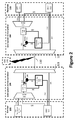
- FIG 2 An embodiment of the invention is shown in figure 2 .
- This embodiment is limited to the case where only one QKD system and one data transmission terminal pair share the same optical fiber.
- This simple case allows a clearer description of the invention.
- the whole considered scenario comprises an emitter 100 and a receiver 110 as in the prior art ( figure 1 ).
- it further comprises a device called QKD System Active combiner 200 placed at emitter 100 output and a device called QKD System Active Splitter 300 placed at receiver 110 input.
- QKD System Active combiner 200 and QKD System Active Splitter 300 are connected by an optical fiber 130.
- the entire system i.e. the QKD apparatus including the emitter, the receiver, the combiner and the splitter is an aspect of the invention. However, it is important to note that both the combiner and the splitter are, per se, aspects of the invention as well.
- the objective of the invention is to guarantee that the classical and quantum channels sharing the same optical fiber will work at any time in an autonomous manner.
- the main activity of this invention is when, or just after, a change in the communication channels occurs.
- QKD System Active Combiner 200 and QKD System Active Splitter 300 roles are:
- QKD Active Combiner 200 and Splitter 300 need processing units (230 and 330) that can collect data, process it and send instructions to other apparatuses. These processing units (230 and 330) can be made with a CPU for example.
- processing units (230 and 330) need to be connected to channel monitoring devices. Any external monitoring device on a quantum channel will introduce errors in the quantum data flow by definition of QKD. Therefore, the monitoring devices for quantum channels are QKD emitter 102 and QKD receiver 112. They both collaborate together in order to compute the QBER value on the quantum channel. In our invention, this QBER value can be sent to the processing units (230 and 330) through dedicated communication links (250 and 350). These communication links (250 and 350) can be made of copper wires for example. There are several ways to monitor a classical channel in order to check if it is working properly or not. One can e.g. measure its optical power or measure its instantaneous Bit Error Rate.
- Any kind of classical channel monitoring requires a detection system, which collects a part of the optical signal of the channel under monitoring, and a pre-processing stage that will extract the expected monitoring value based on the measurement results of the detection system.
- the combination of those two functions is realized monitoring systems 240 or 340.
- the detection system can be made with an optical coupler that taps a portion of the classical channel light, and at least one optical sensor.
- the pre-processing stage can be made with analogic or digital electronics.
- Monitoring systems 240 and 340 are connected to processing units 230 and 330 respectively through communication links 280 and 380. The results of monitoring systems 240 and 340 are sent through these links 280 and 380 to processing units 230 and 330. Data received from the monitoring devices (102 and 112 for quantum channel or 240 and 340 for classical channels) is then processed by processing units 230 and 330 is order to verify if any monitoring signal has changed or if there is any issue on one of the channels.
- processing units In order to be able to fulfill the second role, the processing units (230 and 330) need to be connected to VOA 150 and optical amplifier 160. These connections 290 and 390 can be made with copper wires for example and are used to allow communication between processing units 230 and 330 and VOA 150 and optical amplifier 160 respectively. Via these communications, processing unit 230 is able to adjust the attenuation value of VOA 150 in such a manner that noise in the quantum channels due to the classical channels is low enough to allow the secret key exchange (i.e. the QBER value to be below a predetermined threshold value). In a similar way, the communications via communication link 390 allow processing unit 330 to adjust the gain value of optical amplifier 160 in such a manner that the classical channels work properly (i.e.
- the optical power value on the receiver side is within a predetermined range). Therefore, if any change or issue has been detected by processing units 230 or 330, they can adjust the optical power level of the classical channels in such a way that all channels work correctly. If the two processing units 230 and 330 want to communicate together, they can do it through the service channel of the QKD systems 102 and 112.As can be seen in figure 2 , the invention is located at the WDM multiplexing 121 and demultiplexing 122 stages. There are several options to integrate our invention within those stages.
- figure 2 one presents the option where all classical channels are first multiplexed together with a first stage of WDM multiplexing 215 before being attenuated by VOA 150 and monitored by monitoring device 240 that taps a part of the light propagating in optical fiber 203.
- This optical fiber 203 links the first stage of WDM multiplexing 215 with final WDM multiplexing stage 121.
- All classical channels are attenuated and monitored at once.
- Final WDM multiplexing stage 121 is used to combine the quantum and classical channels within the same fiber 130.
- QKD active splitter 300 A symmetric way to integrate the invention is shown in QKD active splitter 300.
- the first multiplexing stage is implemented with WDM splitter 122.
- This WDM splitter sends out all classical channels within the same optical fiber 213 whereas the quantum channel is send out in a dedicated fiber 114. All the classical channels are monitored with a single monitoring system 340 that taps a portion of the light in fiber 213, and then amplified by a single optical amplifier 160 located on fiber 213. All classical channels are then separated by the last WDM splitter stage 315. The output ports of this splitter 315 are connected to the receivers by the optical fibers 113 and 115.
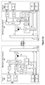
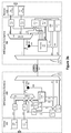
- Figures 3a and 3b describe alternative embodiments.
- FIG. 1 shows one alternative to the option of figure 2 .
- all classical communication channels are monitored at once by monitoring device 240 on the emitter side and by monitoring device 340 on the receiver side. This configuration is similar to the option shown in figure 2 .
- figure 3a The difference between figure 3a and figure 2 is the way the classical channels are attenuated and amplified.
- VOA's 150 as classical channels. All of them are located on the optical fibers between the classical channel emitters and WDM multiplexer 215. Processing unit 230 can act on them separately or not.
- optical amplifiers 160 as classical channels in figure 3a . All amplifiers 160 are located on the optical fibers between WDM demultiplexer 315 and the classical channel receivers. Processing unit 330 can act on them separately or not.
- the system is capable of realizing a tunable and dedicated attenuation / gain variations on a specific channel.
- FIG. 3b shows an alternative embodiment to the one of figure 3a where each QKD system 102 is inside the QKD System Active Combiner 200 and similarly each QKD system 112 is inside the QKD System Active Splitter 300.
- QKD System Active Combiner 200 acts as a dynamic adapter of data and communication signal attenuation on channel 210.
- QKD System Active Splitter 300 acts as a dynamic adapter of data and communication signal amplification on channel 310.
- Figure 4 shows the overall method relating to the apparatus behavior while QKD and communication systems are operating.
- the main aspect of the method is to describe how QKD system active combiner 200 and QKD system active splitter 300 will interact with emitter 100, receiver 110 and main channel 130 in order to ensure data transmission and QKD process while a channel may be added or removed at emitter 100 or receiver 110.
- First step 400 consists in identifying if processing unit 230 at QKD system active combiner 200 or processing unit 330 at QKD active splitter 300 receives a new data. If NO the step 410 redirect the processing units 230 or 330 to step 400, in other words the processing units wait for fresh data. If at least one of the processing units receives data, step 410 makes the processing units move to step 420. On one hand, said new data may be generated by monitoring system 240 or by QKD system 102, on the other hand said new data may be generated by the monitoring system 340 or by QKD system 112. Step 420 consists in checking if the received data is related to the monitoring of the quantum channels or of the classical channels.
- step 430 makes processing units 230 and 330 initiate step 440 defined as 'attenuation/gain process'.
- This step 440 is a whole process in itself that is presented in Figure 5 .
- step 430 makes processing units 230 and 330 initiate step 450 defined as 'QKD Process' This step 450 is a whole process in itself that is presented in Figure 6 ..
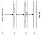
- Figure 5 represents the detailed method associated to the attenuation/gain process presented at step 440 of Figure 4 .
- the process begins first by the processing of the monitoring data (step 500) in order to estimate the optical power of the classical channels.
- This process is done by the processing units 230 and 330 with the data coming from monitoring system 240 or monitoring system 340.
- the result of this step 500 is a measure of the signal intensity in channel 213.
- the second step 510 consists in comparing the signal intensity in the fiber 213 with respect to intensity range on the receiver side for the proper working of the classical channels. If the signal intensity is outside this range, the processing unit 330 calculates the difference between the measured output power at step 500 and the typical range value of the output power on channel 213.
- a typical range value for the signal intensity (or optical power) is between -28dBm and -3dBm. If the measured output power is outside the specified range, then last step 520 consists in modifying the gain of the optical amplifier 160 and the attenuation of the VOA 150 in order to get the output power in the specified range.
- Figure 6 represents the detailed method associated to the QKD process presented at step 450 of Figure 4 .
- step 600 The process starts first with a QKD systems 102 and 112 status check (step 600).
- This step 600 consists in basic verification including for example the answers to the following questions: Is the system on? Are power supplies working properly? Is the connection of the service channel working well?
- step 610 which is specific to the noise that might be introduced by classical channels on quantum channel.
- Step 610 consists in a noise measurement of the QKD single photon detectors (this can be performed by activating the detectors without sending any quantum bits for example).
- the results of the status check and noise measurement performed by the QKD system are sent to processing units 230 and 330.
- Both processing units process those results and determine if the QKD system is in a state allowing it to run properly or not. This means that the additional noise introduced by the classical channels might lead to a QBER value that is above a predetermined threshold. If the noise introduced by classical channel is low enough to allow the proper working of the QKD system, step 620 makes processing units 230 and 330 move directly back to step 400. If the noise introduce by classical channel is too large to allow the proper working of the QKD system, step 620 makes processing units 230 and 330 move to step 630.
- Step 630 consists in the computation by processing units 230 and 330 of the reduction of classical channel power in fiber 130 that needs to be applied to have a QBER value that will be below the predetermined threshold. This computed value is e.g. Y dB.
- Last step 640 consists in modifying the attenuation of VOA 150 and the gain of Amplifier 160 in order to get both,
Landscapes
- Engineering & Computer Science (AREA)
- Physics & Mathematics (AREA)
- Computer Networks & Wireless Communication (AREA)
- Signal Processing (AREA)
- Electromagnetism (AREA)
- Computer Security & Cryptography (AREA)
- Theoretical Computer Science (AREA)
- Optics & Photonics (AREA)
- Optical Communication System (AREA)
Abstract
Description
- The present invention relates to Quantum Cryptography based on Quantum Key Distribution (QKD) and wavelength-division multiplexed (WDM) network infrastructure to provide secure data transmission.
- Quantum Key Distribution involves establishing a key between a sender ("Alice") and a receiver ("Bob") by using either single-photons or weak (e.g., 0.1 photon on average) optical signals (pulses) called "qubits" or "quantum signals" transmitted over a "quantum channel". Unlike classical cryptography whose security depends on computational complexity, the security of quantum cryptography is based on many quantum mechanical principles among which the quantum mechanical principle that any measurement of a quantum system in an unknown state will modify its state. Consequently, an eavesdropper ("Eve") that attempts to intercept or otherwise measure the exchanged qubits introduces errors that reveal her presence.
- The general principles of quantum cryptography were first set forth by Bennett and Brassard in their article "Quantum Cryptography: Public key distribution and coin tossing," Proceedings of the International Conference on Computers, Systems and Signal Processing, Bangalore, India, 1984, pp. 175-179 (IEEE, New York, 1984). Specific QKD systems are described in
U.S. Pat. No. 5,307,410 to Bennett , and in the article by C. H. Bennett entitled "Quantum Cryptography Using Any Two Non-Orthogonal States", Phys. Rev. Lett. 68 3121 (1992). The general process for performing Quantum Key Distribution is described in the book by Bouwmeester et al., "The Physics of Quantum Information," Springer-Verlag 2001, in Section 2.3, pages 27-33. Quantum cryptography has been interdisciplinary developed between the scientific fields of quantum physics, quantum optics, information theory, cryptography and informatics. A survey of the bases and methods as well as the historical development of quantum cryptography is contained in the articles by N. Gisin, G. Ribordy, W. Tittel and H. Zbinden, "Quantum Cryptography", Reviews of Modern Physics. 74, 145 (2002). Quantum cryptography or Quantum Key Distribution (QKD) is a method allowing the distribution of a secret key between two distant parties, the emitter and the receiver, with an information-theoretically provable security as it relies on Quantum physics principles. - As already mentioned above, the security of this method comes from the well-known fact that the measurement of the quantum state of an unknown quantum system modifies the system itself, therefore, a spy eavesdropping on the quantum communication channel cannot get information on the key without introducing errors in the key exchanged between the emitter and the receiver such that eavesdropping attempts can be detected.
- In the following sections, the term "channel" should be understood in a generic sense: a physical medium which can transmit a modulation of some physical property such as an optical signal with a specific intensity. It has to be noted that the term "channel" has a second meaning that is a logical connection over a multiplexed medium. For example, a radio channel is not a physical medium but a signal having a specific wavelength or being within a specific wavelength range. In the specification below, the term channel may be used for both signification, however the context shall make clear to which signification it relates.
- A typical implementation of a cryptographic application based on QKD consists in a cryptographic application running between two remote locations. This implementation involves at least a pair of Quantum Key Distribution devices and a pair of cryptographic application devices using the secret keys exchanged through QKD. One device of each pair is installed in one location, whereas the other device is in the other location. The QKD devices are connected by a quantum communication channel, implemented by an optical fiber and a bidirectional classical communication channel implemented by a second separated optical fiber. This classical communication channel used by the QKD system will be called service channel in the following paragraphs. The pair of cryptographic application devices is connected by a second bidirectional classical communication channel. This classical communication channel used by the cryptographic application will be called data channel in the following paragraphs. Eavesdropping detection is done on the quantum channel (as it consists in the quantum particles) and not on the service channel nor on the data channels running in parallel to the quantum channel.
- Several implementation options are possible for the quantum and service channels in Quantum Key Distribution systems. The most common is the use of separated physical media to carry those communications channels. Note that the physical medium used to carry optical communication channels is made of optical fibers in general. However, other media are possible like e.g. free-space propagation. In the case of communication channels carried by separated optical fibers, the optical fiber, which is dedicated to the quantum channel, is called dark fiber. The bidirectional service channel is carried by two separated optical fibers too. Each fiber carries one direction of the communication channel. In this option, there are no interactions between the different channels because they are carried by physically separated medium.
- In order to have a communication channel which works correctly, it is important that the signal to noise ratio of the received logical signal is large enough. One of the effects of optical fibers on both quantum and classical optical logical signals is the attenuation of these signals along their propagation. This means that the signal level decreases when this signal propagates in an optical fiber. On the other hand, the noise in both quantum and classical channels is mainly due to the noise of the detection system. So, the noise level is independent from the propagation distance within the optical fiber. Therefore, the signal to noise ratio of both communication channel types decreases if the propagation distance of the signal increases. This effect leads to a maximum propagation distance (or a maximum loss value) over which a channel can work. In the case of classical communication channels, the parameter, which is used to determine if the channel has a signal to noise ratio good enough, is the optical intensity of the signal reaching the receiver. If the value of this parameter is in a predetermined range specified by the manufacturer, the channel will work correctly. In the case of quantum communication channels, the parameter, which is used to determine if the channel has a signal to noise ratio good enough, is called quantum bit error rate (QBER). This parameter is somehow the inverse of the signal to noise ratio. The QBER value is measured by QKD systems. When the QBER value is above a predefined threshold value, the QKD system cannot generate any secret keys from the qubit exchange. The higher the QBER value, the larger the error rate with respect to the signal rate. An increase of the error rate can be due either to a decrease of the quantum signal, or to a modification of some QKD system parameters (for example a temperature system fluctuation that modifies the alignments of the optical system, or a change of the intrinsic noise of the single photon detectors in the QKD receiver) or to an eavesdropping attempt.
- Since several years Wavelength Division Multiplexing (WDM) techniques have been investigated to reduce the number of optical fibers that are need in order to run cryptographic applications based on QKD. WDM techniques are used for sharing the same optical fiber between several classical communication channels for few decades. These techniques are based on the affectation of a specific wavelength to each classical channel. In general each communication direction of each channel has its own wavelength. By using component called WDM combiner, it is possible to combine all the wavelengths so that all channels are carried by the same optical fiber. At the end of this fiber, a WDM splitter is used to separate the channels with different wavelengths and send them out from defined output ports. The same techniques can be extended to a combination of quantum and classical communication channels within the same optical fiber. In this case, quantum optical signals (i.e. single photons) propagate in the same fiber than classical signals (i.e. intense optical pulses composed of a large number of photons, e.g. 10'000).
- WDM configurations mixing Quantum Key Distribution and classical communications have been explored since the late 90's with the seminal work of Townsend (Townsend & al., 97). An exemplary embodiment of Quantum Key Distribution system sharing the same optical fiber than classical data transmission systems using Wavelength Division Multiplexing technology is presented in
Figure 1 . As one can see in this figure, it usually comprises anemitter 100 and areceiver 110 connected through anoptical fiber 130. Bothemitter 100 andreceiver 110 embed a plurality ofdata transmission terminals several QKD systems data transmission terminal 101 onemitter 100 side is connected to an associateddata transmission terminal 111 onreceiver 110 side through a classical communication channel. Similarly, eachQKD system 102 onemitter 100 side is connected to an associatedQKD system 112 through a quantum communication channel and a classical communication channel. Each of those quantum or classical channel is associated to a dedicated wavelength value (or a dedicated pair of wavelength values if the channel is bidirectional). The quantum or classical optical signals implementing a quantum or classical channel are sent fromemitter 100 to a wavelength combiner 121 (or wavelength multiplexer) through an optical fiber. This fiber is indexed as 103 for a data channel, 104 for a quantum channel and 105 for a service channel.Wavelength combiner 121 combines all the optical signals with different wavelengths coming from different optical fibers in the sameoptical fiber 130. At this stage all the communication channels are carried by the sameoptical fiber 130 and are spectrally separated. Wavelength splitter 122 (or wavelength demultiplexer) located at the end ofoptical fiber 130 allows the physical separation of all communication channels. Each wavelength is directed to a dedicated optical fiber. This optical fiber corresponding to a specific wavelength value is connected to appropriatedata transmission terminal 111 orQKD system 112. This fiber is indexed as 113 for a data channel, 114 for a quantum channel and 115 for a service channel. - One of the main issues of WDM techniques applied to quantum and classical signals is that classical channel signals may generate noise in the quantum communication channels due to the fact that the classical channel signal intensity is much higher than the single photon level of quantum signals. This increase of noise in the quantum channels leads to an increase of the QBER values that might be above the threshold value allowing the secret key generation.
- There are two reasons for this increase of noise in the quantum channels due to the presence of the classical channels in the optical fiber.
- 1- The first one is defined as channel cross-talk. Channel cross-talk is characterized by an imperfect physical separation of the wavelengths by the wavelength splitter. The cross-talk quality is quantified by the insertion loss (or isolation of one channel compare to another one) experienced by an optical signal at wavelength L1 when it goes out from the optical fiber (113 or 114 or 115) corresponding to the wavelength L2. To avoid that cross-talk forbids the secret key exchange, large isolation values (e.g. >80dB) must be guaranteed by
wavelength splitter 122. The cross-talk is a linear optical effect. This means that all the optical intensity at the wavelength L1 at the entrance ofoptical fiber 130 is still at the same wavelength L1 at the entrance ofwavelength splitter 112. - 2- The second reason for an increase of the noise in quantum channels due to the presence of classical channel is non-linear effects in this fiber. In this case, the optical intensity at the wavelength L1 at the entrance of
optical fiber 130 has another wavelength than L1 (e.g. L2) at the entrance ofwavelength splitter 112. Therefore, this optical intensity will be guided towards the output fiber (113 or 114 or 115) corresponding to L2 and not to L1. There are no spectral way to distinguish between the quantum signals and the noise coming from the classical channels. The most common non-linear effect in optical fibers that affects quantum channels is called Raman Scattering. - The standard way to limit the impact of Raman scattering of classical channels on the quantum channels sharing the same optical fiber is to reduce the optical intensity of those classical channels. This is the reason why, as shown in
figure 1 , classical optical signals may be attenuated by variable optical attenuator (VOA) 150 till an optical power value allowing the proper working of the quantum channels. If the optical power of the classical communication channels is too low onreceiver 110 side, the classical signals can be amplified by anoptical amplifier 160 till the optical power on the receiver is in the range of optical power allowing the proper working of the classical channel. These two specific issues are tackled through the prior art with specific implementations provided in -
US7248695 disclosing a set-up where a deep-notch optical filtering is applied to the classical signals prior to their being multiplexed with the quantum signals to prevent noise generated by the classical signals at the quantum signal wavelength from adversely affecting transmission of quantum signals in the transmission optical fiber. -
US20080273703 describes an apparatus overcoming the issues related to forward/backward Raman scattering and Rayleigh scattering by optically and electronically gating the Single Photons Detectors in the system in a manner that significantly reduces noise from scattered photons. - Eraerds & al., 2010 shares experiments based on 1 Gbps data encryption over one single fiber and challenges relating to multiplexing quantum, service and data channels. In that case, VOA's 150 are used to control the optical power of data channels at the entrance of the
WDM combiner 121 in order to limit the impact of Raman scattering on quantum signal when both classical and quantum signals propagate inoptical fiber 130. - However, the main technical issues tackled above are related to a pre-defined set of quantum and classical communication channels with no dynamic evolution in the implementation. In some applications of these implementations, it is of particular interest for users to be able to add or remove data transmission terminals and/or QKD systems from the Wavelength Division Multiplexing infrastructure. For example, adding a data channel may be justified when a user wants to increase the amount of data and/or the data type (e.g.: video, audio, databases) to be exchanged between the emitter and the receiver, on the other hand it can be useful to remove a channel if a data channel is no more needed. As an example, adding a classical channel increases the intensity level of Raman scattering in
optical fiber 130, which by consequence may lead to an increase of the QBER to a value above the threshold allowing secret key exchanges. Therefore, each time a channel is added, the settings on VOA's 150 andoptical amplifiers 160 need to be adjusted in order to ensure the proper working of both quantum and classical channels. Nevertheless, realizing an adjustment is a challenging step as it may lead to the interruption of the data channels that are already in production and thus affect the whole network operation. - For this reason, a manual adaptation of the actual number of channels is often required in order to ensure that both the QKD systems and data transmission terminals are properly operating when a data or quantum channel is added or removed from the Wavelength Division Multiplexing telecom infrastructure. This manual adaptation is time-consuming and expensive as it requires an operator intervention. Therefore, it would be of particular interest to have a device enabling QKD and classical communications proper operation when adding or removing a channel. This is the main object of this invention.
- A main object of the present invention is to provide a dynamic adaptation device enabling QKD and Data transmission terminal communications proper operation when a WDM communication network architecture changes e.g when adding or removing a channel.
- The above objects of invention are achieved by an apparatus and a method as described in the preamble and description, which is further characterized in that it enables to overcome overall system shutdown risk when adding or removing a data or quantum link.
- The main benefits of the present invention are an automatic implementation of QKD infrastructure within Classical telecom infrastructure exploiting WDM set-up. Therefore, this set-up enables to dynamically adapt on one hand the data and classical communication attenuation at the emitter and the data and classical signal amplification at the receiver. By doing so, when a channel is added or removed, the system performs attenuation and/or amplification signal cycles in order to define the attenuation and amplification signal values that enable both data transmission and quantum key distribution through QKD systems.
- One of the general feature of the invention is to connect the emitter to a QKD System Active combiner and the Receiver to a QKD System Active Splitter enabling to adapt signal attenuation and gain depending on the number of channels used by the
Emitter 100 andReceiver 110 for communication. By doing so the system is capable to ensure system proper operation when the set-up is modified that is to say when a communication channel is added or removed the QKD systems are still able to synchronize and exchange keys and data transmission terminals are able to continuously operate without interruption. Additionally, when a quantum channel is added or removed, QKD systems are still able to synchronize and exchange keys at a defined key rate and Data transmission terminals are able to continuously operate without interruption. - Another object of the invention is to provide an eavesdropping detection method for a QKD-WDM System that can discriminate an eavesdropping attempt from a failure due to improper attenuation/amplification.
- For this reason, a first aspect of the present invention relates to an active channel attenuation/amplification device to be implemented in a QKD system, comprising at least one processing unit adapted to receive a computed a QBER value through a first dedicated communication link and a computed working status of a classical channel through a second dedicated communication link, said processing unit being adapted to judge whether the QBER value and/or the working status of the classical channel has changed, and to control at least one variable optical attenuator and/or at least one amplifier to automatically adjust the attenuation of the variable optical attenuator and/or the gain of the amplifier such that the noise in the quantum channels is lower than a predetermined upper limit to allow secret key exchange, and such that the optical power value on a receiver side is within a predetermined range. Thus, the attenuation/amplification process is adjusted automatically.
- According to a preferred embodiment of the invention, the active channel attenuation/amplification device further comprises a quantum channel monitoring device adapted to compute the QBER value and to send it to the processing unit through the first dedicated communication link.
- Preferably, the active channel attenuation/amplification device further comprises a classical channel monitoring device adapted to compute a working status of a classical channel and to send it to the processing unit through the second dedicated communication link
- According to a preferred embodiment of the invention, the quantum channel monitoring device is a QKD emitter or a QKD receiver.
- Preferably, the active channel attenuation/amplification device further comprising the at least one variable optical attenuator and/or the said amplifier.
- Advantageously, the active channel attenuation/amplification device further comprises a plurality of variable optical attenuators located upstream the classical channel monitoring device and/or a plurality of amplifiers located downstream the classical channel monitoring device.
- Preferably, the optical power is between -28dBm and -3dBm. Within this range, the QKD system works correctly.
- A second aspect of the present invention relates to a QKD System Active combiner adapted to be installed at the output of an emitter in a QKD apparatus and comprising an active channel attenuation/amplification device according to the first aspect of the present invention, wherein said active channel attenuation/amplification device works as an attenuation device.
- Preferably, the QKD System Active combiner comprises the quantum channel monitoring device.
- A third aspect of the present invention relates to a QKD System Active splitter adapted to be installed at the input of a receiver in a QKD apparatus and comprising an active channel attenuation/amplification device according to the first aspect of the present invention, wherein said active channel attenuation/amplification device works as an amplification device.
- Preferably, the QKD System Active splitter comprises the quantum channel monitoring device.
- A fourth aspect of the present invention relates to a QKD apparatus comprising an emitter and a QKD System Active combiner according to the second aspect of the present invention, on an emitting side and a receiver and a QKD System Active splitter according to the third aspect of the present invention, on a receiving side, wherein the emitting side and the receiving side are connected through a classical communication fiber.
- A fifth aspect of the present invention relates to an attenuation/gain method to be carried out in the QKD apparatus of the fourth aspect of the present invention, comprising the steps of processing, in the processing unit of monitoring data coming from the detector/monitor in order to estimate a signal intensity in a channel, comparing the signal intensity in channel with respect to an intensity range, and calculating the difference between the measured intensity and a desired intensity range value on said channel, modifying the gain of the optical amplifier and/or the attenuation of the variable optical attenuator to get the output intensity in the desired intensity range.
- A sixth aspect of the present invention relates to QKD method to be carried out in the QKD apparatus of the fourth aspect of the present invention, comprising the steps of checking the status of the QKD systems, measuring a noise on QKD single photon detectors, determining if the measured noise imped the proper working of the QKD system, if yes, computing a reduction of classical channel power in fiber that needs to be applied to have a QBER value below the predetermined threshold, modifying the attenuation of variable optical attenuator and/or the gain of the amplifier in order to get the classical channel power in the fiber low enough for the proper working of the QKD system.
- A seventh aspect of the present invention relates to active channel attenuation/amplification method to be carried out in the QKD apparatus of the fourth aspect of the present invention. Comprising the steps of identifying if the processing Unit at the QKD System Active Combiner or the Processing Unit at the QKD Active Splitter receives new data, if yes checking if the received data is related to the monitoring of the quantum channels, i.e. new data comes from QKD System, or of the classical channels, i.e. new data comes from detector/monitor, if said new data comes from detector/monitor carrying out the attenuation/gain process of the fifth aspect of the present invention, if said new data comes from QKD System carry out the QKD Process of the sixth aspect of the present invention.
- The invention will now be described more in details in the following description of the preferred embodiments illustrated by the following figures that have an illustrative and non-limiting purpose.
-
-
Figure 1 represents a schematic view of an WDM-based Quantum Key Distribution apparatus of the prior art; -
Figure 2 represents a schematic view of WDM-based Quantum Key Distribution apparatus according to a first embodiment of the invention; -
Figure 3a and3b represent a schematic view of a WDM-based Quantum Key Distribution apparatus according to a second and a third embodiments of the invention; -
Figure 4 is a block diagram representing a method according to a preferred embodiment of the invention; -
Figure 5 is a block diagram representing a monitoring process method according to a preferred embodiment of the invention. -
Figure 6 is a block diagram representing a QKD process according to a preferred embodiment of the invention. - An embodiment of the invention is shown in
figure 2 . This embodiment is limited to the case where only one QKD system and one data transmission terminal pair share the same optical fiber. This simple case allows a clearer description of the invention. As shown infigure 2 , the whole considered scenario comprises anemitter 100 and areceiver 110 as in the prior art (figure 1 ). In addition to these, it further comprises a device called QKD SystemActive combiner 200 placed atemitter 100 output and a device called QKD SystemActive Splitter 300 placed atreceiver 110 input. QKD SystemActive combiner 200 and QKD SystemActive Splitter 300 are connected by anoptical fiber 130. - The entire system, i.e. the QKD apparatus including the emitter, the receiver, the combiner and the splitter is an aspect of the invention. However, it is important to note that both the combiner and the splitter are, per se, aspects of the invention as well.
- Generally speaking, the objective of the invention is to guarantee that the classical and quantum channels sharing the same optical fiber will work at any time in an autonomous manner. Of course, once the settings of
attenuators 150 andoptical amplifiers 160 have been tuned correctly, all the channels should work properly if there are no modifications of any of the communication channels. Therefore, the main activity of this invention is when, or just after, a change in the communication channels occurs. To this end, QKD SystemActive Combiner 200 and QKD SystemActive Splitter 300 roles are: - 1) to collect data from the classical and quantum channels in order to verify if any change occurred or if there is any issue on one of those channels,
- 2) if any change or issue is detected QKD System
Active Combiner 200 andSplitter 300 have to collaborate in order to change the settings so that all the channels are in a proper working state. - In order to be able to fulfill their objective, QKD
Active Combiner 200 andSplitter 300 need processing units (230 and 330) that can collect data, process it and send instructions to other apparatuses. These processing units (230 and 330) can be made with a CPU for example. - In order to be able to fulfill the first role, processing units (230 and 330) need to be connected to channel monitoring devices. Any external monitoring device on a quantum channel will introduce errors in the quantum data flow by definition of QKD. Therefore, the monitoring devices for quantum channels are
QKD emitter 102 andQKD receiver 112. They both collaborate together in order to compute the QBER value on the quantum channel. In our invention, this QBER value can be sent to the processing units (230 and 330) through dedicated communication links (250 and 350). These communication links (250 and 350) can be made of copper wires for example. There are several ways to monitor a classical channel in order to check if it is working properly or not. One can e.g. measure its optical power or measure its instantaneous Bit Error Rate. Any kind of classical channel monitoring requires a detection system, which collects a part of the optical signal of the channel under monitoring, and a pre-processing stage that will extract the expected monitoring value based on the measurement results of the detection system. The combination of those two functions is realized monitoringsystems systems units communication links monitoring systems links units units - In order to be able to fulfill the second role, the processing units (230 and 330) need to be connected to
VOA 150 andoptical amplifier 160. Theseconnections processing units VOA 150 andoptical amplifier 160 respectively. Via these communications, processingunit 230 is able to adjust the attenuation value ofVOA 150 in such a manner that noise in the quantum channels due to the classical channels is low enough to allow the secret key exchange (i.e. the QBER value to be below a predetermined threshold value). In a similar way, the communications viacommunication link 390 allowprocessing unit 330 to adjust the gain value ofoptical amplifier 160 in such a manner that the classical channels work properly (i.e. that the optical power value on the receiver side is within a predetermined range). Therefore, if any change or issue has been detected by processingunits units QKD systems 102 and 112.As can be seen infigure 2 , the invention is located at the WDM multiplexing 121 and demultiplexing 122 stages. There are several options to integrate our invention within those stages. Infigure 2 , one presents the option where all classical channels are first multiplexed together with a first stage of WDM multiplexing 215 before being attenuated byVOA 150 and monitored by monitoringdevice 240 that taps a part of the light propagating inoptical fiber 203. Thisoptical fiber 203 links the first stage of WDM multiplexing 215 with finalWDM multiplexing stage 121. In this option all classical channels are attenuated and monitored at once. FinalWDM multiplexing stage 121 is used to combine the quantum and classical channels within thesame fiber 130. A symmetric way to integrate the invention is shown in QKDactive splitter 300. The first multiplexing stage is implemented withWDM splitter 122. This WDM splitter sends out all classical channels within the sameoptical fiber 213 whereas the quantum channel is send out in adedicated fiber 114. All the classical channels are monitored with asingle monitoring system 340 that taps a portion of the light infiber 213, and then amplified by a singleoptical amplifier 160 located onfiber 213. All classical channels are then separated by the lastWDM splitter stage 315. The output ports of thissplitter 315 are connected to the receivers by theoptical fibers - Alternatively,
Figures 3a and3b describe alternative embodiments. - As mentioned above, there are several options for the integration of the invention compare to the WDM stages. Especially, one can consider to monitor all classical channels at once, like in
figure 2 or to monitor them separately. Moreover, the attenuation of the classical channels can be performed all at once, like infigure 2 , or separately with several VOA's 150. The same considerations apply to theoptical amplifiers 160, one of them can operate on all channels at once, orseveral amplifiers 160 can be used to amplify the classical channels.Figure 3a shows one alternative to the option offigure 2 . In this case, all classical communication channels are monitored at once by monitoringdevice 240 on the emitter side and by monitoringdevice 340 on the receiver side. This configuration is similar to the option shown infigure 2 . The difference betweenfigure 3a andfigure 2 is the way the classical channels are attenuated and amplified. Infigure 3a , there are as many VOA's 150 as classical channels. All of them are located on the optical fibers between the classical channel emitters andWDM multiplexer 215.Processing unit 230 can act on them separately or not. Furthermore, there are as manyoptical amplifiers 160 as classical channels infigure 3a . Allamplifiers 160 are located on the optical fibers betweenWDM demultiplexer 315 and the classical channel receivers.Processing unit 330 can act on them separately or not. - By doing so, the system is capable of realizing a tunable and dedicated attenuation / gain variations on a specific channel.
-
Figure 3b shows an alternative embodiment to the one offigure 3a where eachQKD system 102 is inside the QKD SystemActive Combiner 200 and similarly eachQKD system 112 is inside the QKD SystemActive Splitter 300. In that case QKD SystemActive Combiner 200 acts as a dynamic adapter of data and communication signal attenuation on channel 210. Likewise, QKD SystemActive Splitter 300 acts as a dynamic adapter of data and communication signal amplification on channel 310. -
Figure 4 shows the overall method relating to the apparatus behavior while QKD and communication systems are operating. The main aspect of the method is to describe how QKD systemactive combiner 200 and QKD systemactive splitter 300 will interact withemitter 100,receiver 110 andmain channel 130 in order to ensure data transmission and QKD process while a channel may be added or removed atemitter 100 orreceiver 110. -
First step 400 consists in identifying if processingunit 230 at QKD systemactive combiner 200 orprocessing unit 330 at QKDactive splitter 300 receives a new data. If NO thestep 410 redirect theprocessing units step 410 makes the processing units move to step 420. On one hand, said new data may be generated by monitoringsystem 240 or byQKD system 102, on the other hand said new data may be generated by themonitoring system 340 or byQKD system 112. Step 420 consists in checking if the received data is related to the monitoring of the quantum channels or of the classical channels. - If said new data comes either from monitoring
systems step 430 makesprocessing units step 440 defined as 'attenuation/gain process'. Thisstep 440 is a whole process in itself that is presented inFigure 5 . - If said new data comes either from
QKD systems step 430 makesprocessing units step 450 defined as 'QKD Process' Thisstep 450 is a whole process in itself that is presented inFigure 6 .. -
Figure 5 represents the detailed method associated to the attenuation/gain process presented atstep 440 ofFigure 4 . - The process begins first by the processing of the monitoring data (step 500) in order to estimate the optical power of the classical channels. This process is done by the
processing units monitoring system 240 ormonitoring system 340. The result of thisstep 500 is a measure of the signal intensity inchannel 213. Thesecond step 510 consists in comparing the signal intensity in thefiber 213 with respect to intensity range on the receiver side for the proper working of the classical channels. If the signal intensity is outside this range, theprocessing unit 330 calculates the difference between the measured output power atstep 500 and the typical range value of the output power onchannel 213. A typical range value for the signal intensity (or optical power) is between -28dBm and -3dBm. If the measured output power is outside the specified range, thenlast step 520 consists in modifying the gain of theoptical amplifier 160 and the attenuation of theVOA 150 in order to get the output power in the specified range. -
Figure 6 represents the detailed method associated to the QKD process presented atstep 450 ofFigure 4 . - The process starts first with a
QKD systems step 600 consists in basic verification including for example the answers to the following questions: Is the system on? Are power supplies working properly? Is the connection of the service channel working well? Thisstep 600 is then followed by asecond step 610 which is specific to the noise that might be introduced by classical channels on quantum channel. Step 610 consists in a noise measurement of the QKD single photon detectors (this can be performed by activating the detectors without sending any quantum bits for example). At the end ofstep 610, the results of the status check and noise measurement performed by the QKD system are sent to processingunits step 620 makesprocessing units step 400. If the noise introduce by classical channel is too large to allow the proper working of the QKD system,step 620 makesprocessing units - Step 630 consists in the computation by processing
units fiber 130 that needs to be applied to have a QBER value that will be below the predetermined threshold. This computed value is e.g. Y dB.Last step 640 consists in modifying the attenuation ofVOA 150 and the gain ofAmplifier 160 in order to get both, - 1- the classical channel power in
fiber 130 low enough for the proper working of the QKD system (i.e. to attenuate by at least a value of YdB) and - 2- the optical power of the classical channels on the receiver side in the specified range for a proper working of the classical channels (i.e. to amplify by a gain value similar to the attenuation one (∼YdB)). And then, processing
units
Claims (15)
- Active channel attenuation/amplification device to be implemented with a QKD apparatus, comprising:at least one processing unit (230, 330) adapted to receive a computed a QBER value through a first dedicated communication link (250, 350) and a computed working status of a classical channel (203, 213) through a second dedicated communication link (280, 380),said processing unit (230, 330) being adaptedto judge whether the QBER value and/or the working status of the classical channel has changed, andto control at least one variable optical attenuator (150) and/or at least one amplifier (160) to automatically adjust the attenuation of the variable optical attenuator (150) and/or the gain of the amplifier (160) such that the noise in the quantum channels (104, 114) is lower than a predetermined upper limit to allow secret key exchange, and such that the optical power value on a receiver side is within a predetermined range.
- Active channel attenuation/amplification device according to claim 1, further comprising a quantum channel monitoring device (102, 112) adapted to compute the QBER value and to send it to the processing unit (230, 330) through the first dedicated communication link (250, 350).
- Active channel attenuation/amplification device according to claim 1 or 2, further comprising a classical channel monitoring device (240, 340) adapted to compute a working status of a classical channel (203, 213) and to send it to the processing unit (230, 330) through the second dedicated communication link (280, 380),
- Active channel attenuation/amplification device according to any one of claims 1 to 3, wherein the quantum channel monitoring device is a QKD emitter (102) or a QKD receiver (112).
- Active channel attenuation/amplification device according to any one of claims 1 to 4, further comprising the at least one variable optical attenuator (150) and/or the said amplifier (160).
- Active channel attenuation/amplification device according to any one of claims 1 to 5, further comprising a plurality of variable optical attenuators (150) located upstream the classical channel monitoring device (240) and/or a plurality of amplifiers (160) located downstream the classical channel monitoring device (340).
- Active channel attenuation/amplification device according to any one of claims 1 to 6, wherein the optical power is between -28dBm and -3dBm.
- QKD System Active combiner (200) adapted to be installed at the output of an emitter (100) in a QKD apparatus and comprising an active channel attenuation/amplification device of claims 1-7, wherein said active channel attenuation/amplification device works as an attenuation device.
- QKD System Active combiner (200) according to claim 8, comprising the quantum channel monitoring device (102).
- QKD System Active splitter (300) adapted to be installed at the input of a receiver (110) in a QKD apparatus and comprising an active channel attenuation/amplification device of claims 1-7, wherein said active channel attenuation/amplification device works as an amplification device.
- QKD System Active splitter (200) according to claim 10, comprising the quantum channel monitoring device (112).
- QKD apparatus comprising an emitter (100) and a QKD System Active combiner (200) according to claim 8, on an emitting side and a receiver (110) and a QKD System Active splitter (300) according to claim 10, on a receiving side, wherein the emitting side and the receiving side are connected through a classical communication fiber (130).
- Attenuation/gain method to be carried out in the QKD apparatus of claim 12, comprising the steps of:processing (500), in the processing unit (230, 330) of monitoring data coming from the detector/monitor (240, 340) in order to estimate a signal intensity in a channel (213),comparing (510) the signal intensity in channel (213) with respect to an intensity range, and calculating the difference between the measured intensity and a desired intensity range value on said channel (213).modifying (520) the gain of the optical amplifier (160) and/or the attenuation of the variable optical attenuator (150) to get the output intensity in the desired intensity range.
- QKD method to be carried out in the QKD apparatus of claim 12, comprising the steps of:checking (600) the status of the QKD systems (102 , 112),measuring (610) a noise on QKD single photon detectors,determining (620) if the measured noise prevents the proper working of the QKD system (102, 112), if yes,computing (630) a reduction of classical channel power in fiber (130) that needs to be applied to have a QBER value below the predetermined threshold,modifying (640) the attenuation of variable optical attenuator (150) and/or the gain of the amplifier (160) in order to get the classical channel power in the fiber (130) low enough for the proper working of the QKD system.
- Active channel attenuation/amplification method to be carried out in the QKD apparatus of claim 12. Comprising the steps of:identifying (400) if the processing Unit (230) at the QKD System Active Combiner (200) or the Processing Unit (330) at the QKD Active Splitter (300) receives new data, if yes,checking (420) if the received data is related to the monitoring of the quantum channels, i.e. new data comes from QKD System (102, 112), or of the classical channels, i.e. new data comes from detector/monitor (240, 340),If said new data comes from detector/monitor (240, 340) carrying out (430) the attenuation/gain process (440) of claim 13, If said new data comes from QKD System (102, 112) carry out (430) the QKD Process (450) of claim 14.
Priority Applications (6)
| Application Number | Priority Date | Filing Date | Title |
|---|---|---|---|
| EP16192115.0A EP3301851B1 (en) | 2016-10-03 | 2016-10-03 | Apparatus and method for direct quantum cryptography system implementation over wdm telecommunication network |
| US16/338,649 US10999069B2 (en) | 2016-10-03 | 2017-10-03 | Apparatus and method for direct quantum cryptography system implementation over WDM telecommunication network |
| PCT/EP2017/075043 WO2018065393A1 (en) | 2016-10-03 | 2017-10-03 | Apparatus and method for direct quantum cryptography system implementation over wdm telecommunication network |
| KR1020197012803A KR20190077376A (en) | 2016-10-03 | 2017-10-03 | Apparatus and method for implementing a direct quantum cryptography system over a WDM telecommunication network |
| JP2019517970A JP2019537863A (en) | 2016-10-03 | 2017-10-03 | Apparatus and method for direct implementation of a quantum cryptographic system over a WDM communication network |
| CN201710933682.5A CN107896146B (en) | 2016-10-03 | 2017-10-09 | Active channel attenuation and amplification device and QKD system active beam combiner, beam splitter, QKD device and method including the same |
Applications Claiming Priority (1)
| Application Number | Priority Date | Filing Date | Title |
|---|---|---|---|
| EP16192115.0A EP3301851B1 (en) | 2016-10-03 | 2016-10-03 | Apparatus and method for direct quantum cryptography system implementation over wdm telecommunication network |
Publications (2)
| Publication Number | Publication Date |
|---|---|
| EP3301851A1 true EP3301851A1 (en) | 2018-04-04 |
| EP3301851B1 EP3301851B1 (en) | 2020-12-23 |
Family
ID=57047100
Family Applications (1)
| Application Number | Title | Priority Date | Filing Date |
|---|---|---|---|
| EP16192115.0A Active EP3301851B1 (en) | 2016-10-03 | 2016-10-03 | Apparatus and method for direct quantum cryptography system implementation over wdm telecommunication network |
Country Status (6)
| Country | Link |
|---|---|
| US (1) | US10999069B2 (en) |
| EP (1) | EP3301851B1 (en) |
| JP (1) | JP2019537863A (en) |
| KR (1) | KR20190077376A (en) |
| CN (1) | CN107896146B (en) |
| WO (1) | WO2018065393A1 (en) |
Cited By (7)
| Publication number | Priority date | Publication date | Assignee | Title |
|---|---|---|---|---|
| CN109660347A (en) * | 2019-02-24 | 2019-04-19 | 陕西师范大学 | A kind of Digital Audio Transmission system based on quantum cryptography |
| CN110233670A (en) * | 2019-07-01 | 2019-09-13 | 南京南瑞国盾量子技术有限公司 | A kind of hypotactic quantum key distribution network equipment and method |
| CN110677199A (en) * | 2019-11-21 | 2020-01-10 | 中国人民解放军国防科技大学 | Device and method for detecting laser attack on optical attenuator in quantum key distribution system |
| WO2020193146A1 (en) * | 2019-03-22 | 2020-10-01 | British Telecommunications Public Limited Company | Improvements to qkd network architectures |
| CN116170077A (en) * | 2023-04-24 | 2023-05-26 | 中国科学技术大学 | Quantum and classical laser communication multiplexing receiving device and system |
| EP4387125A1 (en) * | 2022-12-15 | 2024-06-19 | Kabushiki Kaisha Toshiba | Multiplexing device, qkd system, qkd device, multiplexing method, and adjustment method |
| US12200115B2 (en) | 2019-03-22 | 2025-01-14 | British Telecommunications Public Limited Company | QKD network architectures |
Families Citing this family (18)
| Publication number | Priority date | Publication date | Assignee | Title |
|---|---|---|---|---|
| CN106685655B (en) * | 2017-01-16 | 2019-08-16 | 华南师范大学 | A kind of phase polarization multiple degrees of freedom modulation QKD network system and method |
| CN108737082B (en) * | 2017-04-24 | 2020-11-17 | 华为技术有限公司 | Signal receiving device and receiving method |
| EP3782325B1 (en) * | 2018-04-19 | 2024-01-10 | Telefonaktiebolaget Lm Ericsson (Publ) | Path computation engine and method of configuring an optical path for quantum key distribution |
| CN109347553B (en) * | 2018-11-30 | 2020-05-15 | 中国联合网络通信集团有限公司 | Method and device for measuring attenuation value of optical fiber |
| KR102666217B1 (en) * | 2019-09-05 | 2024-05-14 | 주식회사 케이티 | System and apparatus for distributing quantum cryptography key |
| US11139963B2 (en) * | 2019-09-12 | 2021-10-05 | General Electric Company | Communication systems and methods |
| CA3156799A1 (en) | 2019-10-02 | 2021-04-08 | The Research Foundation For The State University Of New York | Quantum network devices, systems, and methods |
| KR102418595B1 (en) * | 2019-12-23 | 2022-07-08 | 주식회사 케이티 | System, apparatus and method for channel multiplexing quantum communication |
| CN111162866B (en) * | 2019-12-31 | 2023-07-28 | 广东尤科泊得科技发展有限公司 | A system and method for quantum-classical co-fiber transmission based on mode division multiplexing |
| CN111130782B (en) * | 2020-03-31 | 2020-08-28 | 北京中创为南京量子通信技术有限公司 | Quantum key distribution networking method and system |
| GB2600446A (en) | 2020-10-29 | 2022-05-04 | Airbus Sas | Free space optical communications terminal |
| KR20230093242A (en) * | 2020-11-02 | 2023-06-27 | 엘지전자 주식회사 | Syndrome comparison-based QBER estimation method and apparatus in QKD system |
| CN114528021B (en) * | 2022-01-28 | 2022-11-08 | 中国人民解放军战略支援部队信息工程大学 | Time-sharing multiplexing quantum measurement and control system and low-power-consumption high-efficiency quantum measurement and control compiling method |
| JP7775157B2 (en) * | 2022-07-22 | 2025-11-25 | 株式会社東芝 | QKD system, monitoring device, multiplexing device and program |
| US12381722B2 (en) * | 2022-08-01 | 2025-08-05 | Mellanox Technologies, Ltd. | Bi-directional quantum interconnects |
| EP4369649A1 (en) * | 2022-11-10 | 2024-05-15 | Terra Quantum AG | Method and system for quantum key distribution |
| WO2024231998A1 (en) * | 2023-05-09 | 2024-11-14 | 日本電気株式会社 | Transmitter for quantum cryptography device, method for measuring signal light, and signal light measurement system |
| WO2025191639A1 (en) * | 2024-03-11 | 2025-09-18 | 日本電気株式会社 | Communication device, communication system, and communication method |
Citations (5)
| Publication number | Priority date | Publication date | Assignee | Title |
|---|---|---|---|---|
| US5307410A (en) | 1993-05-25 | 1994-04-26 | International Business Machines Corporation | Interferometric quantum cryptographic key distribution system |
| US20040136709A1 (en) * | 2003-01-15 | 2004-07-15 | Wei Yang | Microprocessor-based optical signal conditioner |
| US7248695B1 (en) | 2006-02-10 | 2007-07-24 | Magiq Technologies, Inc. | Systems and methods for transmitting quantum and classical signals over an optical network |
| US20080273703A1 (en) | 2004-09-15 | 2008-11-06 | Magiq Technologies, Inc. | Dual-Gated Qkd System for Wdm Networks |
| US20160241936A1 (en) * | 2015-02-17 | 2016-08-18 | Fujitsu Limited | Optical transmission device, optical transmission system, and optical transmission control method |
Family Cites Families (6)
| Publication number | Priority date | Publication date | Assignee | Title |
|---|---|---|---|---|
| JPH07109916B2 (en) * | 1988-05-26 | 1995-11-22 | 浜松ホトニクス株式会社 | Light intensity stabilizer |
| US6959171B2 (en) * | 2002-02-28 | 2005-10-25 | Intel Corporation | Data transmission rate control |
| CN102739394B (en) * | 2012-06-07 | 2013-11-06 | 中国科学技术大学 | Light quantum phase modulating system |
| EP3082276A4 (en) * | 2013-12-10 | 2017-11-08 | Mitsubishi Electric Corporation | Wavelength-multiplexed transport system |
| CA2946535C (en) * | 2014-04-21 | 2020-02-25 | Arris Enterprises Llc | Apparatus and system for managing wavelengths in optical networks |
| CN103929251B (en) * | 2014-04-22 | 2017-05-24 | 华南师范大学 | Low noise QKD and WDM classic communication network compatible method and device |
-
2016
- 2016-10-03 EP EP16192115.0A patent/EP3301851B1/en active Active
-
2017
- 2017-10-03 JP JP2019517970A patent/JP2019537863A/en active Pending
- 2017-10-03 US US16/338,649 patent/US10999069B2/en active Active
- 2017-10-03 KR KR1020197012803A patent/KR20190077376A/en not_active Ceased
- 2017-10-03 WO PCT/EP2017/075043 patent/WO2018065393A1/en not_active Ceased
- 2017-10-09 CN CN201710933682.5A patent/CN107896146B/en active Active
Patent Citations (5)
| Publication number | Priority date | Publication date | Assignee | Title |
|---|---|---|---|---|
| US5307410A (en) | 1993-05-25 | 1994-04-26 | International Business Machines Corporation | Interferometric quantum cryptographic key distribution system |
| US20040136709A1 (en) * | 2003-01-15 | 2004-07-15 | Wei Yang | Microprocessor-based optical signal conditioner |
| US20080273703A1 (en) | 2004-09-15 | 2008-11-06 | Magiq Technologies, Inc. | Dual-Gated Qkd System for Wdm Networks |
| US7248695B1 (en) | 2006-02-10 | 2007-07-24 | Magiq Technologies, Inc. | Systems and methods for transmitting quantum and classical signals over an optical network |
| US20160241936A1 (en) * | 2015-02-17 | 2016-08-18 | Fujitsu Limited | Optical transmission device, optical transmission system, and optical transmission control method |
Non-Patent Citations (8)
| Title |
|---|
| "Proceedings of the International Conference on Computers, Systems and Signal Processing, Bangalore, India", 1984, IEEE, article "Quantum Cryptography: Public key distribution and coin tossing", pages: 175 - 179 |
| AKIHIRO TANAKA ET AL: "High-Speed Quantum Key Distribution System for 1-Mbps Real-Time Key Generation", IEEE JOURNAL OF QUANTUM ELECTRONICS, IEEE SERVICE CENTER, PISCATAWAY, NJ, USA, vol. 48, no. 4, 1 April 2012 (2012-04-01), pages 542 - 550, XP011421468, ISSN: 0018-9197, DOI: 10.1109/JQE.2012.2187327 * |
| BOUWMEESTER ET AL.: "The Physics of Quantum Information", 2001, SPRINGER-VERLAG, pages: 27 - 33 |
| C. H. BENNETT: "Quantum Cryptography Using Any Two Non-Orthogonal States", PHYS. REV. LETT., vol. 68, 1992, pages 3121 |
| N. GISIN; G. RIBORDY; W. TITTEL; H. ZBINDEN: "Quantum Cryptography", REVIEWS OF MODERN PHYSICS., vol. 74, 2002, pages 145 |
| PATRICK ERAERDS ET AL: "Quantum key distribution and 1 Gbit/s data encryption over a single fibre", ARXIV.ORG, CORNELL UNIVERSITY LIBRARY, 201 OLIN LIBRARY CORNELL UNIVERSITY ITHACA, NY 14853, 9 December 2009 (2009-12-09), XP080381539 * |
| SASAKI MASAHIDE ET AL: "Quantum Photonic Network: Concept, Basic Tools, and Future Issues", IEEE JOURNAL OF SELECTED TOPICS IN QUANTUM ELECTRONICS, IEEE SERVICE CENTER, PISCATAWAY, NJ, US, vol. 21, no. 3, 1 May 2015 (2015-05-01), pages 1 - 13, XP011567918, ISSN: 1077-260X, [retrieved on 20141215], DOI: 10.1109/JSTQE.2014.2369507 * |
| YOSHINO K ET AL: "Long-term field demonstration of WDM quantum key distribution system with stabilization control", 2013 CONFERENCE ON LASERS AND ELECTRO-OPTICS PACIFIC RIM (CLEOPR), IEEE, 30 June 2013 (2013-06-30), pages 1 - 2, XP032481875, DOI: 10.1109/CLEOPR.2013.6600228 * |
Cited By (12)
| Publication number | Priority date | Publication date | Assignee | Title |
|---|---|---|---|---|
| CN109660347A (en) * | 2019-02-24 | 2019-04-19 | 陕西师范大学 | A kind of Digital Audio Transmission system based on quantum cryptography |
| WO2020193146A1 (en) * | 2019-03-22 | 2020-10-01 | British Telecommunications Public Limited Company | Improvements to qkd network architectures |
| CN113545003A (en) * | 2019-03-22 | 2021-10-22 | 英国电讯有限公司 | Improvements to the QKD network architecture |
| CN113545003B (en) * | 2019-03-22 | 2024-04-30 | 英国电讯有限公司 | System and method for transmitting optical pulses |
| US12200115B2 (en) | 2019-03-22 | 2025-01-14 | British Telecommunications Public Limited Company | QKD network architectures |
| US12250298B2 (en) | 2019-03-22 | 2025-03-11 | British Telecommunications Public Limited Company | To QKD network architectures |
| CN110233670A (en) * | 2019-07-01 | 2019-09-13 | 南京南瑞国盾量子技术有限公司 | A kind of hypotactic quantum key distribution network equipment and method |
| CN110233670B (en) * | 2019-07-01 | 2022-04-26 | 南京南瑞国盾量子技术有限公司 | Quantum key distribution network device and method with master-slave structure |
| CN110677199A (en) * | 2019-11-21 | 2020-01-10 | 中国人民解放军国防科技大学 | Device and method for detecting laser attack on optical attenuator in quantum key distribution system |
| EP4387125A1 (en) * | 2022-12-15 | 2024-06-19 | Kabushiki Kaisha Toshiba | Multiplexing device, qkd system, qkd device, multiplexing method, and adjustment method |
| CN116170077A (en) * | 2023-04-24 | 2023-05-26 | 中国科学技术大学 | Quantum and classical laser communication multiplexing receiving device and system |
| CN116170077B (en) * | 2023-04-24 | 2023-08-29 | 中国科学技术大学 | Quantum and classical laser communication multiplexing receiving device and system |
Also Published As
| Publication number | Publication date |
|---|---|
| CN107896146A (en) | 2018-04-10 |
| WO2018065393A1 (en) | 2018-04-12 |
| CN107896146B (en) | 2022-02-25 |
| EP3301851B1 (en) | 2020-12-23 |
| JP2019537863A (en) | 2019-12-26 |
| KR20190077376A (en) | 2019-07-03 |
| US20200044835A1 (en) | 2020-02-06 |
| US10999069B2 (en) | 2021-05-04 |
Similar Documents
| Publication | Publication Date | Title |
|---|---|---|
| US10999069B2 (en) | Apparatus and method for direct quantum cryptography system implementation over WDM telecommunication network | |
| EP3560140B1 (en) | Apparatus and method for enhancing secret key rate exchange over quantum channel in quantum key distribution systems | |
| US20250358226A1 (en) | Encryption key generation | |
| CN108199768B (en) | Measuring equipment irrelevant quantum key distribution system and method based on W state | |
| US7248695B1 (en) | Systems and methods for transmitting quantum and classical signals over an optical network | |
| US11616645B1 (en) | Encrypted data transmission in optical- and radio-access networks based on quantum key distribution | |
| CN106533565B (en) | Quantum secret communication method and apparatus | |
| KR101916995B1 (en) | System and method for high speed communication with enhanced security | |
| Sun et al. | Experimental integration of quantum key distribution and gigabit-capable passive optical network | |
| CN113454944A (en) | Efficient quantum key security in point-to-multipoint passive optical networks | |
| Gagliano et al. | Quantum key distribution spectral allocation and performance in coexistence with passive optical network standards | |
| CN109039589B (en) | A device and method for multiplexing optical fiber transmission of quantum signals and classical signals | |
| CN111492599A (en) | Optical data transmission system | |
| CN113545003B (en) | System and method for transmitting optical pulses | |
| KR102828245B1 (en) | Apparatus and Method for Mutual Authenticating Quantum Entity based on Measurment Device Independent Quantum Key Distribution | |
| Guan et al. | Physical layer security of space-division multiplexed fiber-optic communication systems in the presence of multiple eavesdroppers | |
| KR101898417B1 (en) | System and method for high speed communication with enhanced security | |
| KR101897531B1 (en) | System and method for high speed communication with enhanced security | |
| HK1237547A1 (en) | Information communication system, information communication method, and device | |
| HK1238019A1 (en) | Information communication system, information communication method, and device |
Legal Events
| Date | Code | Title | Description |
|---|---|---|---|
| PUAI | Public reference made under article 153(3) epc to a published international application that has entered the european phase |
Free format text: ORIGINAL CODE: 0009012 |
|
| STAA | Information on the status of an ep patent application or granted ep patent |
Free format text: STATUS: THE APPLICATION HAS BEEN PUBLISHED |
|
| AK | Designated contracting states |
Kind code of ref document: A1 Designated state(s): AL AT BE BG CH CY CZ DE DK EE ES FI FR GB GR HR HU IE IS IT LI LT LU LV MC MK MT NL NO PL PT RO RS SE SI SK SM TR |
|
| AX | Request for extension of the european patent |
Extension state: BA ME |
|
| STAA | Information on the status of an ep patent application or granted ep patent |
Free format text: STATUS: REQUEST FOR EXAMINATION WAS MADE |
|
| 17P | Request for examination filed |
Effective date: 20180815 |
|
| RBV | Designated contracting states (corrected) |
Designated state(s): AL AT BE BG CH CY CZ DE DK EE ES FI FR GB GR HR HU IE IS IT LI LT LU LV MC MK MT NL NO PL PT RO RS SE SI SK SM TR |
|
| STAA | Information on the status of an ep patent application or granted ep patent |
Free format text: STATUS: EXAMINATION IS IN PROGRESS |
|
| 17Q | First examination report despatched |
Effective date: 20181005 |
|
| GRAP | Despatch of communication of intention to grant a patent |
Free format text: ORIGINAL CODE: EPIDOSNIGR1 |
|
| STAA | Information on the status of an ep patent application or granted ep patent |
Free format text: STATUS: GRANT OF PATENT IS INTENDED |
|
| RIC1 | Information provided on ipc code assigned before grant |
Ipc: H04L 9/08 20060101AFI20200518BHEP Ipc: H04B 10/70 20130101ALI20200518BHEP |
|
| INTG | Intention to grant announced |
Effective date: 20200604 |
|
| GRAS | Grant fee paid |
Free format text: ORIGINAL CODE: EPIDOSNIGR3 |
|
| GRAA | (expected) grant |
Free format text: ORIGINAL CODE: 0009210 |
|
| STAA | Information on the status of an ep patent application or granted ep patent |
Free format text: STATUS: THE PATENT HAS BEEN GRANTED |
|
| AK | Designated contracting states |
Kind code of ref document: B1 Designated state(s): AL AT BE BG CH CY CZ DE DK EE ES FI FR GB GR HR HU IE IS IT LI LT LU LV MC MK MT NL NO PL PT RO RS SE SI SK SM TR |
|
| REG | Reference to a national code |
Ref country code: GB Ref legal event code: FG4D |
|
| REG | Reference to a national code |
Ref country code: DE Ref legal event code: R096 Ref document number: 602016050142 Country of ref document: DE |
|
| REG | Reference to a national code |
Ref country code: AT Ref legal event code: REF Ref document number: 1348768 Country of ref document: AT Kind code of ref document: T Effective date: 20210115 Ref country code: CH Ref legal event code: NV Representative=s name: KATZAROV SA, CH |
|
| REG | Reference to a national code |
Ref country code: IE Ref legal event code: FG4D |
|
| PG25 | Lapsed in a contracting state [announced via postgrant information from national office to epo] |
Ref country code: NO Free format text: LAPSE BECAUSE OF FAILURE TO SUBMIT A TRANSLATION OF THE DESCRIPTION OR TO PAY THE FEE WITHIN THE PRESCRIBED TIME-LIMIT Effective date: 20210323 Ref country code: RS Free format text: LAPSE BECAUSE OF FAILURE TO SUBMIT A TRANSLATION OF THE DESCRIPTION OR TO PAY THE FEE WITHIN THE PRESCRIBED TIME-LIMIT Effective date: 20201223 Ref country code: GR Free format text: LAPSE BECAUSE OF FAILURE TO SUBMIT A TRANSLATION OF THE DESCRIPTION OR TO PAY THE FEE WITHIN THE PRESCRIBED TIME-LIMIT Effective date: 20210324 Ref country code: FI Free format text: LAPSE BECAUSE OF FAILURE TO SUBMIT A TRANSLATION OF THE DESCRIPTION OR TO PAY THE FEE WITHIN THE PRESCRIBED TIME-LIMIT Effective date: 20201223 |
|
| REG | Reference to a national code |
Ref country code: AT Ref legal event code: MK05 Ref document number: 1348768 Country of ref document: AT Kind code of ref document: T Effective date: 20201223 |
|
| REG | Reference to a national code |
Ref country code: NL Ref legal event code: MP Effective date: 20201223 |
|
| PG25 | Lapsed in a contracting state [announced via postgrant information from national office to epo] |
Ref country code: SE Free format text: LAPSE BECAUSE OF FAILURE TO SUBMIT A TRANSLATION OF THE DESCRIPTION OR TO PAY THE FEE WITHIN THE PRESCRIBED TIME-LIMIT Effective date: 20201223 Ref country code: BG Free format text: LAPSE BECAUSE OF FAILURE TO SUBMIT A TRANSLATION OF THE DESCRIPTION OR TO PAY THE FEE WITHIN THE PRESCRIBED TIME-LIMIT Effective date: 20210323 Ref country code: LV Free format text: LAPSE BECAUSE OF FAILURE TO SUBMIT A TRANSLATION OF THE DESCRIPTION OR TO PAY THE FEE WITHIN THE PRESCRIBED TIME-LIMIT Effective date: 20201223 |
|
| PG25 | Lapsed in a contracting state [announced via postgrant information from national office to epo] |
Ref country code: NL Free format text: LAPSE BECAUSE OF FAILURE TO SUBMIT A TRANSLATION OF THE DESCRIPTION OR TO PAY THE FEE WITHIN THE PRESCRIBED TIME-LIMIT Effective date: 20201223 Ref country code: HR Free format text: LAPSE BECAUSE OF FAILURE TO SUBMIT A TRANSLATION OF THE DESCRIPTION OR TO PAY THE FEE WITHIN THE PRESCRIBED TIME-LIMIT Effective date: 20201223 |
|
| REG | Reference to a national code |
Ref country code: LT Ref legal event code: MG9D |
|
| PG25 | Lapsed in a contracting state [announced via postgrant information from national office to epo] |
Ref country code: EE Free format text: LAPSE BECAUSE OF FAILURE TO SUBMIT A TRANSLATION OF THE DESCRIPTION OR TO PAY THE FEE WITHIN THE PRESCRIBED TIME-LIMIT Effective date: 20201223 Ref country code: CZ Free format text: LAPSE BECAUSE OF FAILURE TO SUBMIT A TRANSLATION OF THE DESCRIPTION OR TO PAY THE FEE WITHIN THE PRESCRIBED TIME-LIMIT Effective date: 20201223 Ref country code: SM Free format text: LAPSE BECAUSE OF FAILURE TO SUBMIT A TRANSLATION OF THE DESCRIPTION OR TO PAY THE FEE WITHIN THE PRESCRIBED TIME-LIMIT Effective date: 20201223 Ref country code: LT Free format text: LAPSE BECAUSE OF FAILURE TO SUBMIT A TRANSLATION OF THE DESCRIPTION OR TO PAY THE FEE WITHIN THE PRESCRIBED TIME-LIMIT Effective date: 20201223 Ref country code: RO Free format text: LAPSE BECAUSE OF FAILURE TO SUBMIT A TRANSLATION OF THE DESCRIPTION OR TO PAY THE FEE WITHIN THE PRESCRIBED TIME-LIMIT Effective date: 20201223 Ref country code: SK Free format text: LAPSE BECAUSE OF FAILURE TO SUBMIT A TRANSLATION OF THE DESCRIPTION OR TO PAY THE FEE WITHIN THE PRESCRIBED TIME-LIMIT Effective date: 20201223 Ref country code: PT Free format text: LAPSE BECAUSE OF FAILURE TO SUBMIT A TRANSLATION OF THE DESCRIPTION OR TO PAY THE FEE WITHIN THE PRESCRIBED TIME-LIMIT Effective date: 20210423 |
|
| PG25 | Lapsed in a contracting state [announced via postgrant information from national office to epo] |
Ref country code: PL Free format text: LAPSE BECAUSE OF FAILURE TO SUBMIT A TRANSLATION OF THE DESCRIPTION OR TO PAY THE FEE WITHIN THE PRESCRIBED TIME-LIMIT Effective date: 20201223 Ref country code: AT Free format text: LAPSE BECAUSE OF FAILURE TO SUBMIT A TRANSLATION OF THE DESCRIPTION OR TO PAY THE FEE WITHIN THE PRESCRIBED TIME-LIMIT Effective date: 20201223 |
|
| REG | Reference to a national code |
Ref country code: DE Ref legal event code: R097 Ref document number: 602016050142 Country of ref document: DE |
|
| PG25 | Lapsed in a contracting state [announced via postgrant information from national office to epo] |
Ref country code: IS Free format text: LAPSE BECAUSE OF FAILURE TO SUBMIT A TRANSLATION OF THE DESCRIPTION OR TO PAY THE FEE WITHIN THE PRESCRIBED TIME-LIMIT Effective date: 20210423 |
|
| PG25 | Lapsed in a contracting state [announced via postgrant information from national office to epo] |
Ref country code: AL Free format text: LAPSE BECAUSE OF FAILURE TO SUBMIT A TRANSLATION OF THE DESCRIPTION OR TO PAY THE FEE WITHIN THE PRESCRIBED TIME-LIMIT Effective date: 20201223 Ref country code: IT Free format text: LAPSE BECAUSE OF FAILURE TO SUBMIT A TRANSLATION OF THE DESCRIPTION OR TO PAY THE FEE WITHIN THE PRESCRIBED TIME-LIMIT Effective date: 20201223 |
|
| PLBE | No opposition filed within time limit |
Free format text: ORIGINAL CODE: 0009261 |
|
| STAA | Information on the status of an ep patent application or granted ep patent |
Free format text: STATUS: NO OPPOSITION FILED WITHIN TIME LIMIT |
|
| PG25 | Lapsed in a contracting state [announced via postgrant information from national office to epo] |
Ref country code: DK Free format text: LAPSE BECAUSE OF FAILURE TO SUBMIT A TRANSLATION OF THE DESCRIPTION OR TO PAY THE FEE WITHIN THE PRESCRIBED TIME-LIMIT Effective date: 20201223 |
|
| 26N | No opposition filed |
Effective date: 20210924 |
|
| PG25 | Lapsed in a contracting state [announced via postgrant information from national office to epo] |
Ref country code: ES Free format text: LAPSE BECAUSE OF FAILURE TO SUBMIT A TRANSLATION OF THE DESCRIPTION OR TO PAY THE FEE WITHIN THE PRESCRIBED TIME-LIMIT Effective date: 20201223 |
|
| PG25 | Lapsed in a contracting state [announced via postgrant information from national office to epo] |
Ref country code: SI Free format text: LAPSE BECAUSE OF FAILURE TO SUBMIT A TRANSLATION OF THE DESCRIPTION OR TO PAY THE FEE WITHIN THE PRESCRIBED TIME-LIMIT Effective date: 20201223 |
|
| PG25 | Lapsed in a contracting state [announced via postgrant information from national office to epo] |
Ref country code: IS Free format text: LAPSE BECAUSE OF FAILURE TO SUBMIT A TRANSLATION OF THE DESCRIPTION OR TO PAY THE FEE WITHIN THE PRESCRIBED TIME-LIMIT Effective date: 20210423 |
|
| REG | Reference to a national code |
Ref country code: BE Ref legal event code: MM Effective date: 20211031 |
|
| PG25 | Lapsed in a contracting state [announced via postgrant information from national office to epo] |
Ref country code: MC Free format text: LAPSE BECAUSE OF FAILURE TO SUBMIT A TRANSLATION OF THE DESCRIPTION OR TO PAY THE FEE WITHIN THE PRESCRIBED TIME-LIMIT Effective date: 20201223 |
|
| PG25 | Lapsed in a contracting state [announced via postgrant information from national office to epo] |
Ref country code: LU Free format text: LAPSE BECAUSE OF NON-PAYMENT OF DUE FEES Effective date: 20211003 Ref country code: BE Free format text: LAPSE BECAUSE OF NON-PAYMENT OF DUE FEES Effective date: 20211031 |
|
| PG25 | Lapsed in a contracting state [announced via postgrant information from national office to epo] |
Ref country code: FR Free format text: LAPSE BECAUSE OF NON-PAYMENT OF DUE FEES Effective date: 20211031 |
|
| PG25 | Lapsed in a contracting state [announced via postgrant information from national office to epo] |
Ref country code: IE Free format text: LAPSE BECAUSE OF NON-PAYMENT OF DUE FEES Effective date: 20211003 |
|
| PG25 | Lapsed in a contracting state [announced via postgrant information from national office to epo] |
Ref country code: HU Free format text: LAPSE BECAUSE OF FAILURE TO SUBMIT A TRANSLATION OF THE DESCRIPTION OR TO PAY THE FEE WITHIN THE PRESCRIBED TIME-LIMIT; INVALID AB INITIO Effective date: 20161003 |
|
| PG25 | Lapsed in a contracting state [announced via postgrant information from national office to epo] |
Ref country code: CY Free format text: LAPSE BECAUSE OF FAILURE TO SUBMIT A TRANSLATION OF THE DESCRIPTION OR TO PAY THE FEE WITHIN THE PRESCRIBED TIME-LIMIT Effective date: 20201223 |
|
| P01 | Opt-out of the competence of the unified patent court (upc) registered |
Effective date: 20230526 |
|
| PG25 | Lapsed in a contracting state [announced via postgrant information from national office to epo] |
Ref country code: MK Free format text: LAPSE BECAUSE OF FAILURE TO SUBMIT A TRANSLATION OF THE DESCRIPTION OR TO PAY THE FEE WITHIN THE PRESCRIBED TIME-LIMIT Effective date: 20201223 |
|
| PG25 | Lapsed in a contracting state [announced via postgrant information from national office to epo] |
Ref country code: TR Free format text: LAPSE BECAUSE OF FAILURE TO SUBMIT A TRANSLATION OF THE DESCRIPTION OR TO PAY THE FEE WITHIN THE PRESCRIBED TIME-LIMIT Effective date: 20201223 |
|
| PG25 | Lapsed in a contracting state [announced via postgrant information from national office to epo] |
Ref country code: MT Free format text: LAPSE BECAUSE OF FAILURE TO SUBMIT A TRANSLATION OF THE DESCRIPTION OR TO PAY THE FEE WITHIN THE PRESCRIBED TIME-LIMIT Effective date: 20201223 |
|
| REG | Reference to a national code |
Ref country code: CH Ref legal event code: U11 Free format text: ST27 STATUS EVENT CODE: U-0-0-U10-U11 (AS PROVIDED BY THE NATIONAL OFFICE) Effective date: 20251101 |
|
| PGFP | Annual fee paid to national office [announced via postgrant information from national office to epo] |
Ref country code: DE Payment date: 20251020 Year of fee payment: 10 |
|
| PGFP | Annual fee paid to national office [announced via postgrant information from national office to epo] |
Ref country code: GB Payment date: 20251024 Year of fee payment: 10 |
|
| PGFP | Annual fee paid to national office [announced via postgrant information from national office to epo] |
Ref country code: CH Payment date: 20251101 Year of fee payment: 10 |