EP3301840A1 - Method for link adaptation and power amplifier voltage control and system therefor - Google Patents
Method for link adaptation and power amplifier voltage control and system therefor Download PDFInfo
- Publication number
- EP3301840A1 EP3301840A1 EP17190547.4A EP17190547A EP3301840A1 EP 3301840 A1 EP3301840 A1 EP 3301840A1 EP 17190547 A EP17190547 A EP 17190547A EP 3301840 A1 EP3301840 A1 EP 3301840A1
- Authority
- EP
- European Patent Office
- Prior art keywords
- supply voltage
- quality indicator
- transceiver
- power amplifier
- signal
- Prior art date
- Legal status (The legal status is an assumption and is not a legal conclusion. Google has not performed a legal analysis and makes no representation as to the accuracy of the status listed.)
- Withdrawn
Links
Images





Classifications
-
- H—ELECTRICITY
- H04—ELECTRIC COMMUNICATION TECHNIQUE
- H04W—WIRELESS COMMUNICATION NETWORKS
- H04W52/00—Power management, e.g. Transmission Power Control [TPC] or power classes
- H04W52/04—Transmission power control [TPC]
- H04W52/18—TPC being performed according to specific parameters
- H04W52/26—TPC being performed according to specific parameters using transmission rate or quality of service QoS [Quality of Service]
- H04W52/262—TPC being performed according to specific parameters using transmission rate or quality of service QoS [Quality of Service] taking into account adaptive modulation and coding [AMC] scheme
-
- H—ELECTRICITY
- H04—ELECTRIC COMMUNICATION TECHNIQUE
- H04L—TRANSMISSION OF DIGITAL INFORMATION, e.g. TELEGRAPHIC COMMUNICATION
- H04L1/00—Arrangements for detecting or preventing errors in the information received
- H04L1/0001—Systems modifying transmission characteristics according to link quality, e.g. power backoff
- H04L1/0002—Systems modifying transmission characteristics according to link quality, e.g. power backoff by adapting the transmission rate
-
- H—ELECTRICITY
- H04—ELECTRIC COMMUNICATION TECHNIQUE
- H04L—TRANSMISSION OF DIGITAL INFORMATION, e.g. TELEGRAPHIC COMMUNICATION
- H04L1/00—Arrangements for detecting or preventing errors in the information received
- H04L1/0001—Systems modifying transmission characteristics according to link quality, e.g. power backoff
- H04L1/0009—Systems modifying transmission characteristics according to link quality, e.g. power backoff by adapting the channel coding
-
- H—ELECTRICITY
- H04—ELECTRIC COMMUNICATION TECHNIQUE
- H04L—TRANSMISSION OF DIGITAL INFORMATION, e.g. TELEGRAPHIC COMMUNICATION
- H04L1/00—Arrangements for detecting or preventing errors in the information received
- H04L1/0001—Systems modifying transmission characteristics according to link quality, e.g. power backoff
- H04L1/0015—Systems modifying transmission characteristics according to link quality, e.g. power backoff characterised by the adaptation strategy
-
- H—ELECTRICITY
- H04—ELECTRIC COMMUNICATION TECHNIQUE
- H04W—WIRELESS COMMUNICATION NETWORKS
- H04W52/00—Power management, e.g. Transmission Power Control [TPC] or power classes
- H04W52/02—Power saving arrangements
- H04W52/0209—Power saving arrangements in terminal devices
- H04W52/0251—Power saving arrangements in terminal devices using monitoring of local events, e.g. events related to user activity
- H04W52/0254—Power saving arrangements in terminal devices using monitoring of local events, e.g. events related to user activity detecting a user operation or a tactile contact or a motion of the device
-
- H—ELECTRICITY
- H04—ELECTRIC COMMUNICATION TECHNIQUE
- H04W—WIRELESS COMMUNICATION NETWORKS
- H04W52/00—Power management, e.g. Transmission Power Control [TPC] or power classes
- H04W52/02—Power saving arrangements
- H04W52/0209—Power saving arrangements in terminal devices
- H04W52/0261—Power saving arrangements in terminal devices managing power supply demand, e.g. depending on battery level
- H04W52/0296—Power saving arrangements in terminal devices managing power supply demand, e.g. depending on battery level switching to a backup power supply
-
- H—ELECTRICITY
- H04—ELECTRIC COMMUNICATION TECHNIQUE
- H04W—WIRELESS COMMUNICATION NETWORKS
- H04W52/00—Power management, e.g. Transmission Power Control [TPC] or power classes
- H04W52/04—Transmission power control [TPC]
-
- H—ELECTRICITY
- H04—ELECTRIC COMMUNICATION TECHNIQUE
- H04W—WIRELESS COMMUNICATION NETWORKS
- H04W52/00—Power management, e.g. Transmission Power Control [TPC] or power classes
- H04W52/04—Transmission power control [TPC]
- H04W52/18—TPC being performed according to specific parameters
- H04W52/20—TPC being performed according to specific parameters using error rate
-
- H—ELECTRICITY
- H04—ELECTRIC COMMUNICATION TECHNIQUE
- H04W—WIRELESS COMMUNICATION NETWORKS
- H04W52/00—Power management, e.g. Transmission Power Control [TPC] or power classes
- H04W52/04—Transmission power control [TPC]
- H04W52/18—TPC being performed according to specific parameters
- H04W52/24—TPC being performed according to specific parameters using SIR [Signal to Interference Ratio] or other wireless path parameters
- H04W52/241—TPC being performed according to specific parameters using SIR [Signal to Interference Ratio] or other wireless path parameters taking into account channel quality metrics, e.g. SIR, SNR, CIR or Eb/lo
-
- H—ELECTRICITY
- H04—ELECTRIC COMMUNICATION TECHNIQUE
- H04W—WIRELESS COMMUNICATION NETWORKS
- H04W52/00—Power management, e.g. Transmission Power Control [TPC] or power classes
- H04W52/04—Transmission power control [TPC]
- H04W52/18—TPC being performed according to specific parameters
- H04W52/24—TPC being performed according to specific parameters using SIR [Signal to Interference Ratio] or other wireless path parameters
- H04W52/245—TPC being performed according to specific parameters using SIR [Signal to Interference Ratio] or other wireless path parameters taking into account received signal strength
-
- H—ELECTRICITY
- H04—ELECTRIC COMMUNICATION TECHNIQUE
- H04W—WIRELESS COMMUNICATION NETWORKS
- H04W52/00—Power management, e.g. Transmission Power Control [TPC] or power classes
- H04W52/04—Transmission power control [TPC]
- H04W52/18—TPC being performed according to specific parameters
- H04W52/26—TPC being performed according to specific parameters using transmission rate or quality of service QoS [Quality of Service]
- H04W52/267—TPC being performed according to specific parameters using transmission rate or quality of service QoS [Quality of Service] taking into account the information rate
-
- H—ELECTRICITY
- H04—ELECTRIC COMMUNICATION TECHNIQUE
- H04W—WIRELESS COMMUNICATION NETWORKS
- H04W52/00—Power management, e.g. Transmission Power Control [TPC] or power classes
- H04W52/04—Transmission power control [TPC]
- H04W52/18—TPC being performed according to specific parameters
- H04W52/28—TPC being performed according to specific parameters using user profile, e.g. mobile speed, priority or network state, e.g. standby, idle or non-transmission
- H04W52/283—Power depending on the position of the mobile
-
- H—ELECTRICITY
- H04—ELECTRIC COMMUNICATION TECHNIQUE
- H04W—WIRELESS COMMUNICATION NETWORKS
- H04W52/00—Power management, e.g. Transmission Power Control [TPC] or power classes
- H04W52/02—Power saving arrangements
- H04W52/0209—Power saving arrangements in terminal devices
- H04W52/0225—Power saving arrangements in terminal devices using monitoring of external events, e.g. the presence of a signal
-
- H—ELECTRICITY
- H04—ELECTRIC COMMUNICATION TECHNIQUE
- H04W—WIRELESS COMMUNICATION NETWORKS
- H04W84/00—Network topologies
- H04W84/02—Hierarchically pre-organised networks, e.g. paging networks, cellular networks, WLAN [Wireless Local Area Network] or WLL [Wireless Local Loop]
- H04W84/10—Small scale networks; Flat hierarchical networks
- H04W84/12—WLAN [Wireless Local Area Networks]
-
- Y—GENERAL TAGGING OF NEW TECHNOLOGICAL DEVELOPMENTS; GENERAL TAGGING OF CROSS-SECTIONAL TECHNOLOGIES SPANNING OVER SEVERAL SECTIONS OF THE IPC; TECHNICAL SUBJECTS COVERED BY FORMER USPC CROSS-REFERENCE ART COLLECTIONS [XRACs] AND DIGESTS
- Y02—TECHNOLOGIES OR APPLICATIONS FOR MITIGATION OR ADAPTATION AGAINST CLIMATE CHANGE
- Y02D—CLIMATE CHANGE MITIGATION TECHNOLOGIES IN INFORMATION AND COMMUNICATION TECHNOLOGIES [ICT], I.E. INFORMATION AND COMMUNICATION TECHNOLOGIES AIMING AT THE REDUCTION OF THEIR OWN ENERGY USE
- Y02D30/00—Reducing energy consumption in communication networks
- Y02D30/70—Reducing energy consumption in communication networks in wireless communication networks
Definitions
- This disclosure relates generally to wireless communication systems, and more particularly to link adaptation and power amplifier voltage control at a wireless communication device.
- Link adaptation or adaptive modulation and coding
- the performance of a wireless data communication system can be limited by path-loss, interference due to signals coming from other transmitters, sensitivity of the receiver, available transmitter power margin, and the like.
- a wireless local area network (WLAN) communication system can use an algorithm that adapts the modulation and coding scheme according to the quality of the radio channel, thereby improving the bit rate and robustness of data transmission.
- the performance of a communication system can be measured based on link data rate, network capacity, range, power consumption, and the like.
- the process of link adaptation is a dynamic one and the signal and protocol parameters change as the radio link conditions change.
- Link adaptation can utilize channel state information provided by a transmitter, such as a WLAN access point, however legacy systems may not provide this state information. Accordingly, link adaptation can be provided based only on reception parameters and analytics determined by a WLAN node.
- Mobile communication devices are typically powered by an included battery having limited capacity.
- One approach to reducing power consumption that has been proposed is to employ envelope tracking, wherein a voltage provided to an RF power amplifier is configured to track the actual waveform of the modulated radio frequency signal provided to an antenna.
- envelope tracking approach is both difficult and expensive to implement, rendering implementation impractical. Accordingly, other techniques for reducing power dissipation in a wireless transceiver are needed. In some situations, it may be necessary to compromise data rate, range, and other performance metrics in order to conserve power. For example, a device may simply limit transmit power to a fixed, reduced, level.
- a method comprising: determining a quality indicator designating a quality of packet reception at a wireless local area network transceiver; selecting a Modulation and Coding Scheme (MCS) index value based on the quality indicator; and determining a supply voltage provided to a radio frequency power amplifier at the transceiver based on the quality indicator.
- MCS Modulation and Coding Scheme
- the quality indicator is determined based on a received signal strength indication (RSSI) measured at the transceiver.
- RSSI received signal strength indication
- the quality indicator is determined based on a packet error rate (PER) measured at the transceiver.
- PER packet error rate
- the quality indicator is determined based on an error vector magnitude (EVM) measured at the transceiver.
- EVM error vector magnitude
- the quality indicator is determined based on a signal-to-noise ratio (SNR) measured at the transceiver.
- SNR signal-to-noise ratio
- the method may further comprise determining the supply voltage based on a transmit power control (TPC) value.
- TPC transmit power control
- the method may further comprise determining the supply voltage based on a data transmission throughput at the transceiver.
- the method may further comprise maintaining the determined supply voltage for a period greater than the duration of transmission of a single data packet.
- the method may further comprise determining that a current quality of packet reception supports increasing the MCS index; and lowering the supply voltage instead of increasing the MCS index.
- a method comprising: determining a quality indicator designating a quality of packet reception at a wireless local area network transceiver; determining that a current quality of packet reception supports increasing a Modulation and Coding Scheme (MCS) index; and lowering a supply voltage provided to a radio frequency power amplifier at the transceiver instead of increasing the MCS index.
- MCS Modulation and Coding Scheme
- the quality indicator is determined based on a received signal strength indication (RSSI) measured at the transceiver.
- RSSI received signal strength indication
- the quality indicator is determined based on a packet error rate (PER) measured at the transceiver.
- PER packet error rate
- the quality indicator is determined based on an error vector magnitude (EVM) measured at the transceiver.
- EVM error vector magnitude
- the quality indicator is determined based on a signal-to-noise ratio (SNR) measured at the transceiver.
- SNR signal-to-noise ratio
- a method comprising: determining a quality indicator designating a quality of packet reception at a wireless local area network transceiver; estimating a distance from the transceiver to a media access point generating in communication with the transceiver; and determining a supply voltage provided to a radio frequency power amplifier at the transceiver, wherein if the distance is less than a first threshold distance, selecting a first supply voltage; if the distance is greater than the first threshold distance and less than a second threshold distance, selecting a second supply voltage greater than the first supply voltage; and if the distance is greater than the second threshold distance, selecting a third supply voltage less than the second supply voltage.
- the quality indicator is determined based on a received signal strength indication (RSSI) measured at the transceiver.
- RSSI received signal strength indication
- the quality indicator is determined based on a packet error rate (PER) measured at the transceiver.
- PER packet error rate
- the quality indicator is determined based on an error vector magnitude (EVM) measured at the transceiver.
- EVM error vector magnitude
- the quality indicator is determined based on a signal-to-noise ratio (SNR) measured at the transceiver.
- SNR signal-to-noise ratio
- a wireless data communication system comprising: a receiver; a signal analytics device configured to determine a signal reception characteristic of the receiver; a processor configured to determine a quality indicator based on the reception characteristic; a radio-frequency power amplifier coupled to an antenna; and a power supply configured to provide a supply voltage to the power amplifier, the supply voltage determined based on the quality indicator.
- the signal reception characteristic is a received signal strength indication (RSSI).
- RSSI received signal strength indication
- the signal reception characteristic is a packet error rate (PER).
- PER packet error rate
- the signal reception characteristic is an error vector magnitude (EVM)).
- EVM error vector magnitude
- the supply voltage determined based on the quality indicator is maintained for a period greater than the duration of transmission of a single data packet.
- FIGs. 1-9 illustrate techniques for controlling an average voltage level supplied to a radio-frequency power amplifier based on a derived quality indicator.
- the quality indicator is configured to track one or more radio signal reception characteristics, for example a received signal strength indicator (RSSI), a packet error ratio (PER), an error vector magnitude (EVM), a signal-to-noise ratio (SNR), and the like.
- the power amplifier supply voltage level can be determined in concert with link adaptation protocols to provide average power tracking to improve energy efficiency in wireless local area networks.
- the techniques disclosed herein are described in the context of the Institute of Electrical and Electronics Engineers (IEEE) 802.11 specification for wireless networking, but are applicable to other wireless communication transceivers.
- IEEE Institute of Electrical and Electronics Engineers
- these techniques can be implemented on legacy infrastructures that do not support hand-shaking protocols between a wireless device and an associated wireless access point, such as systems compliant with specifications 802.11a, 802.11b, 802.11g, and the like.
- the disclosed techniques can be integrated with support for transmit power control (TPC).
- TPC transmit power control
- the average power tracking techniques disclosed herein adjust the power amplifier supply voltage at a rate commensurate with a packet rate or slower, such as across a single burst.
- FIG. 1 is a block diagram illustrating a device including a wireless communication transceiver 100 according to a specific embodiment of the present application.
- Transceiver 100 includes an antenna 102, a receive chain (RX) 104, a processor 106, a transmit chain (TX) 108, an exciter stage 110, a radio-frequency power amplifier 112, and a switch mode power supply 114.
- Transceiver 100 can be included in an information handling system that supports wireless data communications, such as a mobile computer connected to the Internet through a wireless local area network (WLAN).
- WLAN wireless local area network
- Antenna 102 is coupled to an input of receive chain 104 and to an output of power amplifier 110.
- Antenna 102 supports transmission and reception of a wireless data communication signal to/from a wireless access point, such as a router or modem providing a WLAN.
- Receiver chain 104 typically includes receiver front-end circuity providing reception, filtering and intermediate or baseband frequency conversion. For clarity, specific details known in the art are not shown at FIG. 1 .
- receive chain 104 can include a signal processor to perform demodulation, de-mapping, bit de-interleaving, channel estimation and decoding, and the like.
- the receive chain 104 can determine signal and other reception characteristics, such as RSSI, SNR, PER, EVM, and other parameters that transceiver 100 may utilize to perform link adaptation.
- Processor 106 includes an input coupled to an output of receiver chain 104, an output QI coupled to an input of transmit chain 108, an output TPC coupled to an input of exciter 110 to implement transmit power control, and an output coupled to SMPS 114 to provide an average power tracking signal APT.
- Processor 106 provides link adaptation functions, including adaptive modulation and coding scheme index selection based on various signal quality and error information received from receiver chain 104. For example, processor 106 can utilize a rate adaptation algorithm that adapts a modulation and coding scheme (MCS) index according to signal quality and channel performance.
- Link adaptation can utilize state information provided by the access point transmitter, but such information may not be provided if one or more nodes on the WLAN are only compliant with a legacy specification.
- Adaptive modulation systems can improve rate of transmission, and/or bit error rates, by adjusting an MCS index in response to varying reception quality and data throughput performance.
- the MCS index specifies the number of spatial streams, modulation type, coding rate, and channel bandwidth.
- Link adaptation protocols can be designed to optimize data throughput by balancing transmission rate with packet error rate. A packet error requires retransmission of the corresponding packet, diminishing performance.
- processor 106 is responsible for implementing a locally-inferred quality indicator (QI) that can be used to implement a link adaptation policy and also to modulate a supply voltage (V PA ) provided to power amplifier 112 to reduce transmission energy and improve energy efficiency.
- QI quality indicator
- V PA supply voltage
- processor 106 can perform link adaptation in concert with average power tracking (APT) to optimize the combination of throughput and power consumption. Operation of processor 106 is described in detail below with reference to FIGs. 2-9 .
- Transmit chain 108 can receive data from the information handling system (not shown) for transmission over the WLAN.
- Transmit chain 108 can include a transmit signal processor and modulation circuits as known in the art.
- Signal QI generated at processor 106 can provide the basis for determining a MCS index to be implemented by transmit chain 108.
- Exciter 110 includes an input for receiving a low-level modulated signal from transmit chain 108, and an input for receiving the transmit power control signal TPC.
- An output signal of exciter 110 is amplified by power amplifier 112 for transmission via antenna 102.
- a supply voltage V PA for power amplifier 112 is generated by SMPS 114 based on the average power tracking signal APT generated by processor 106 based on the quality indicator QI.
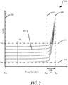
- FIG. 2 is a graph 200 illustrating power dissipation at transceiver 100 of FIG. 1 as a function of power amplifier supply voltage, according to a specific embodiment of the present application.
- Graph 200 includes a horizontal axis representing power output of power amplifier 112, and a vertical axis representing electric current supplied to power amplifier 112.
- Graph 200 includes a set of curves illustrating the power amplifier current corresponding to variations in the power amplifier supply voltage V PA .
- Reference 210 indicates a current I min corresponding to a minimum value of V PA
- reference 211 indicates a current I max corresponding to a maximum value of signal V PA .
- I min can correspond to a supply voltage V PA of 1.2 volts
- I max can correspond to a supply voltage V PA of 2.8 volts.
- Reference 220 indicates a minimum power level, P min
- reference 221 indicates a maximum desired power level P max , provided by power amplifier 112.
- P min and P max transistors included in power amplifier 112 are operating substantially linearly.
- P sat an operating region known as saturation, P sat , indicated by region between reference 221 and reference 222, where operation of the transistors is increasingly non-linear.
- OFDM orthogonal frequency-division multiplexing
- PAR peak to average ratio
- OFDM PAR is typically 10 dB, dropping typical power amplifier efficiency to below 10%.
- V PA supply voltage
- V PA can be adjusted in concert with selection of an MCS index to provide the most power-efficient combination of MCS index, V PA and transmission power.
- FIG. 3 is a block diagram 300 illustrating average power tracking based on a quality indicator derived from reception characteristics, according to a specific embodiment of the present application.
- Diagram 300 includes V PA control logic 302, SMPS 114, power amplifier 112, and antenna 102.
- V PA control logic 302 includes a look-up table 304, which is configured to generate average power tracking signal APT based on one or more radio signal reception characteristics, represented by variables X, Y, and Z.
- the signal reception characteristics can include RSSI, SNR, PER, EVM, and other parameters corresponding to reception or data throughput.
- Look-up table 304 can be configured to regulate signal APT directly.
- look-up table 304 can determine a value of the quality indicator QI, and signal APT can be generated based on quality indicator QI.
- look-up table 304 can be programmable, to define how each of parameters X, Y, and Z contributes to determining the quality indicator QI and signal APT.
- Another software or hardware technique can be utilized to generate quality indicator QI and signal APT based on the signal characteristics.
- Received signal strength indicator is a measurement of power present in a received radio signal, and can be determined at receive chain 104 of FIG. 1 .
- RSSI is typically measured in the intermediate frequency (IF) stage, but can be determined in the baseband signal chain.
- Specification 802.11 also includes definition of a received channel power indicator (RCPI), which is a measure of the received radio frequency power in a selected channel over the preamble and the entire received frame.
- RSSI and RCPI while indicative of reception power, may not always correlate with overall transmission quality, for example due to interference.
- SNR Signal to noise ratio
- Packet error ratio is the number of incorrectly received data packets divided by the total number of received packets. A packet is declared incorrect if at least one bit is erroneous. PER, and bit error rate (BER) may be affected by transmission channel noise, interference, distortion, bit synchronization problems, attenuation, wireless multipath, and the like. PER affects data throughput because the packet exhibiting an error requires retransmission.
- Error vector magnitude is a measure used to quantify the performance of a digital radio transmitter or receiver.
- EVM indicates how ideally constellation points are located, for example, how far the constellation points deviate from the ideal locations.
- EVM can be referred to as receive constellation error (RCE).
- RCE receive constellation error
- Noise, distortion, spurious signals, and phase noise all degrade EVM, and therefore EVM provides a comprehensive measure of the quality of the radio receiver or transmitter for use in digital communications.
- An error vector is a vector in the I-Q plane between the ideal constellation point and the point received by the receiver. The average power of the error vector, normalized to signal power, is the EVM.
- Each of the parameters RSSI, SNR, PER, and EVM can be used alone, or in combination with one or more other parameters, to determine the quality indicator QI disclosed herein.
- look-up table 304 can define weightings for each parameter, the weightings identifying how much each parameter contributes to the quality indicator. While a look-up table is shown for simplicity, one of skill will appreciate that the contributory weight and influence on the quality indicator can be calculated using an equation or algorithm.
- FIG. 4 is a flow diagram illustrating a method 400 for generating the quality indicator of FIG. 1 according to a specific embodiment of the present application.
- Method 400 begins at block 401 where a received signal strength indicator (RSSI) is determined at a receive chain based on characteristics of a signal received at a wireless communication receiver.
- RSSI received signal strength indicator
- PER packet error ratio
- SNR signal-to-noise ratio
- EVM error vector magnitude
- the signal characterization parameters can be collected at an interval corresponding to a single packet.
- the signal characterization parameters can be collected at an interval corresponding to transmission of multiple packets, such as an interval corresponding to a burst or longer.
- Method 400 completes at block 405 where a quality indicator is generated based on one or more of the parameters determined at blocks 402-404. As with the determination of the signal characteristics, generation of the quality indicator can be performed at an interval corresponding to a single packet, an interval corresponding to transmission of multiple packets, or less frequently. Note that only those parameters used to calculate the QI value need to be determined, and FIG. 4 illustrates a particular embodiment where four exemplary parameters are used.
- FIG. 5 is a flow diagram illustrating a method 500 for adjusting a power amplifier voltage according to a specific embodiment of the present application.
- Method 500 begins at block 501 where a quality indicator is determined based on signal reception characteristics. For example, one or more reception characteristics, such as RSSI, SNR, PER, and EVM can be evaluated and used to generate the quality indicator.
- Method 500 proceeds to block 502 where a supply voltage to a radio frequency power amplifier is adjusted based on the quality indicator.
- processor 106 can evaluate the one or more signal characteristics to determine a quality indicator QI, and the corresponding average power tracking signal APT. Signal APT configures SMPS 114 to output a desired power amplifier supply voltage V PA .
- V PA is maintained throughout the duration of the transmission of a data packet, or longer.
- a larger value of QI can correspond to a reduction in the value of V PA .
- the translation function relating QI to V PA can be linear, non-linear, continuous, or discontinuous.
- a value of V PA can be configured to both decrease and increase over specific ranges of the quality indicator.
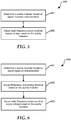
- FIG. 6 is a flow diagram illustrating a method 600 for adjusting a power amplifier voltage according to another embodiment of the present application.
- Method 600 begins at block 601 where a quality indicator is determined based on signal reception characteristics. For example, one or more reception characteristics, such as RSSI, SNR, PER, and EVM can be evaluated and used to generate the quality indicator.
- MCS modulation and coding scheme
- Method 600 proceeds to block 603 where a supply voltage to radio frequency power amplifier is adjusted based on the quality indicator.
- a link adaptation policy can incorporate variations in power amplifier voltage in concert with selection of a desired MCS index.
- FIG. 7 is a flow diagram illustrating a method 700 for adjusting a power amplifier voltage and a modulation coding scheme according to a specific embodiment of the present application.
- Method 700 begins at block 701 where a quality indicator is determined based on signal reception characteristics such as RSSI, SNR, PER, and EVM.
- TPC transmit power control
- a device including a wireless data transceiver may provide a user interface or a power-saving application for controlling transmitter power.
- MCS modulation and coding scheme
- Method 700 concludes at block 704 where a supply voltage to radio frequency power amplifier is adjusted based on the quality indicator.
- a link adaptation policy can incorporate variations in power amplifier voltage in concert with selection of a desired MCS index.
- FIG. 8 is a flow diagram illustrating a method 800 for adjusting a power amplifier voltage according to another embodiment of the present application.
- Method 800 begins at block 801 where a quality indicator is determined based on signal reception characteristics such as RSSI, SNR, PER, and EVM.
- MCS modulation and coding scheme
- Method 800 concludes at block 803 where, instead of increasing the MCS index, a supply voltage to a radio-frequency power amplifier is decreased.
- a link adaptation algorithm can favor power conservation over maximizing data throughput.
- FIG. 9 is a flow diagram illustrating a method 900 for adjusting a power amplifier voltage according to yet another embodiment of the present application.
- Method 900 begins at block 901 where a quality indicator is determined based on signal reception characteristics such as RSSI, SNR, PER, and EVM.
- the method continues at block 902 where a distance between a wireless data transceiver to an access point transmitter is estimated based on the quality indicator.
- a supply voltage V PA provided to a radio-frequency power amplifier is adjusted based on the estimated distance. In particular, if the estimated distance is less than a first predetermined value, supply voltage V PA is set to a first value.
- supply voltage V PA is set to a second value that is higher than the first value. If the estimated distance is greater than the second value, supply voltage V PA is set to a third value that is less than the second value.
- a method includes determining a quality indicator designating a quality of packet reception at a wireless local area network transceiver, selecting a Modulation and Coding Scheme (MCS) index value based on the quality indicator, and determining a supply voltage provided to a radio frequency power amplifier at the transceiver based on the quality indicator.
- the quality indicator is determined based on one or more of a received signal strength indication (RSSI) measured at the transceiver, a packet error rate (PER) measured at the transceiver, an error vector magnitude (EVM) measured at the transceiver, and a signal-to-noise ratio (SNR) measured at the transceiver.
- RSSI received signal strength indication
- PER packet error rate
- EVM error vector magnitude
- SNR signal-to-noise ratio
- the supply voltage is determined based on one or more of a transmit power control (TPC) value, and a data transmission throughput at the transceiver. In an embodiment of the first aspect, the determined supply voltage is maintained for a period greater than the duration of transmission of a single data packet. In an embodiment of the first aspect, the method includes determining that a current quality of packet reception supports increasing the MCS index, and lowering the supply voltage instead of increasing the MCS index.
- TPC transmit power control
- a method in a second aspect, includes determining a quality indicator designating a quality of packet reception at a wireless local area network transceiver, determining that a current quality of packet reception supports increasing a Modulation and Coding Scheme (MCS) index; and lowering a supply voltage provided to a radio frequency power amplifier at the transceiver instead of increasing the MCS index.
- the quality indicator is determined based on one or more of a received signal strength indication (RSSI) measured at the transceiver, a packet error rate (PER) measured at the transceiver, an error vector magnitude (EVM) measured at the transceiver, and a signal-to-noise ratio (SNR) measured at the transceiver.
- RSSI received signal strength indication
- PER packet error rate
- EVM error vector magnitude
- SNR signal-to-noise ratio
- a method in a third aspect, includes determining a quality indicator designating a quality of packet reception at a wireless local area network transceiver, estimating a distance from the transceiver to a media access point generating in communication with the transceiver.
- a supply voltage provided to a radio frequency power amplifier at the transceiver is determined based on the estimated distance. If the distance is less than a first threshold distance, selecting a first supply voltage. If the distance is greater than the first threshold distance and less than a second threshold distance, selecting a second supply voltage greater than the first supply voltage. If the distance is greater than the second threshold distance, selecting a third supply voltage less than the second supply voltage.
- the quality indicator is determined based on one or more of a received signal strength indication (RSSI) measured at the transceiver, a packet error rate (PER) measured at the transceiver, an error vector magnitude (EVM) measured at the transceiver, and a signal-to-noise ratio (SNR) measured at the transceiver.
- RSSI received signal strength indication
- PER packet error rate
- EVM error vector magnitude
- SNR signal-to-noise ratio
- a wireless data communication system includes a receiver, a signal analytics device configured to determine a signal reception characteristic of the receiver, a processor configured to determine a quality indicator based on the reception characteristic, a radio-frequency power amplifier coupled to an antenna, and a power supply configured to provide a supply voltage to the power amplifier.
- the supply voltage provided to the power amplifier is determined based on the quality indicator.
- the quality indicator is determined based on one or more of a received signal strength indication (RSSI) measured at the transceiver, a packet error rate (PER) measured at the transceiver, an error vector magnitude (EVM) measured at the transceiver, and a signal-to-noise ratio (SNR) measured at the transceiver.
- the supply voltage is maintained for a period greater than the duration of transmission of a single data packet.
- a method includes determining a quality indicator designating a quality of packet reception at a wireless local area network transceiver.
- a Modulation and Coding Scheme (MCS) index value is selected based on the quality indicator.
- a supply voltage provided to a radio frequency power amplifier is determined based on the quality indicator.
Landscapes
- Engineering & Computer Science (AREA)
- Computer Networks & Wireless Communication (AREA)
- Signal Processing (AREA)
- Quality & Reliability (AREA)
- Transmitters (AREA)
Abstract
Description
- This disclosure relates generally to wireless communication systems, and more particularly to link adaptation and power amplifier voltage control at a wireless communication device.
- Link adaptation, or adaptive modulation and coding, is a term used in wireless communications to denote the matching of the modulation, coding and other signal and protocol parameters to the conditions on the radio link. The performance of a wireless data communication system can be limited by path-loss, interference due to signals coming from other transmitters, sensitivity of the receiver, available transmitter power margin, and the like. A wireless local area network (WLAN) communication system can use an algorithm that adapts the modulation and coding scheme according to the quality of the radio channel, thereby improving the bit rate and robustness of data transmission. The performance of a communication system can be measured based on link data rate, network capacity, range, power consumption, and the like. The process of link adaptation is a dynamic one and the signal and protocol parameters change as the radio link conditions change. This is especially true for a mobile device, as a user's distance from a wireless access hub transmitter is likely to vary over time. Link adaptation can utilize channel state information provided by a transmitter, such as a WLAN access point, however legacy systems may not provide this state information. Accordingly, link adaptation can be provided based only on reception parameters and analytics determined by a WLAN node.
- Mobile communication devices are typically powered by an included battery having limited capacity. One approach to reducing power consumption that has been proposed is to employ envelope tracking, wherein a voltage provided to an RF power amplifier is configured to track the actual waveform of the modulated radio frequency signal provided to an antenna. However, the envelope tracking approach is both difficult and expensive to implement, rendering implementation impractical. Accordingly, other techniques for reducing power dissipation in a wireless transceiver are needed. In some situations, it may be necessary to compromise data rate, range, and other performance metrics in order to conserve power. For example, a device may simply limit transmit power to a fixed, reduced, level.
- Aspects of the disclosure are defined in the claims. In a first aspect there is described a method comprising: determining a quality indicator designating a quality of packet reception at a wireless local area network transceiver; selecting a Modulation and Coding Scheme (MCS) index value based on the quality indicator; and determining a supply voltage provided to a radio frequency power amplifier at the transceiver based on the quality indicator.
- In one or more embodiments, the quality indicator is determined based on a received signal strength indication (RSSI) measured at the transceiver.
- In one or more embodiments, the quality indicator is determined based on a packet error rate (PER) measured at the transceiver.
- In one or more embodiments, the quality indicator is determined based on an error vector magnitude (EVM) measured at the transceiver.
- In one or more embodiments, the quality indicator is determined based on a signal-to-noise ratio (SNR) measured at the transceiver.
- In one or more embodiments, the method may further comprise determining the supply voltage based on a transmit power control (TPC) value.
- In one or more embodiments, the method may further comprise determining the supply voltage based on a data transmission throughput at the transceiver.
- In one or more embodiments, the method may further comprise maintaining the determined supply voltage for a period greater than the duration of transmission of a single data packet.
- In one or more embodiments, the method may further comprise determining that a current quality of packet reception supports increasing the MCS index; and lowering the supply voltage instead of increasing the MCS index.
- In a second aspect, there is described a method comprising: determining a quality indicator designating a quality of packet reception at a wireless local area network transceiver; determining that a current quality of packet reception supports increasing a Modulation and Coding Scheme (MCS) index; and lowering a supply voltage provided to a radio frequency power amplifier at the transceiver instead of increasing the MCS index.
- In one or more embodiments, the quality indicator is determined based on a received signal strength indication (RSSI) measured at the transceiver.
- In one or more embodiments, the quality indicator is determined based on a packet error rate (PER) measured at the transceiver.
- In one or more embodiments, the quality indicator is determined based on an error vector magnitude (EVM) measured at the transceiver.
- In one or more embodiments, the quality indicator is determined based on a signal-to-noise ratio (SNR) measured at the transceiver.
- In a third aspect, there is described a method comprising: determining a quality indicator designating a quality of packet reception at a wireless local area network transceiver; estimating a distance from the transceiver to a media access point generating in communication with the transceiver; and determining a supply voltage provided to a radio frequency power amplifier at the transceiver, wherein if the distance is less than a first threshold distance, selecting a first supply voltage; if the distance is greater than the first threshold distance and less than a second threshold distance, selecting a second supply voltage greater than the first supply voltage; and if the distance is greater than the second threshold distance, selecting a third supply voltage less than the second supply voltage.
- In one or more embodiments, the quality indicator is determined based on a received signal strength indication (RSSI) measured at the transceiver.
- In one or more embodiments, the quality indicator is determined based on a packet error rate (PER) measured at the transceiver.
- In one or more embodiments, the quality indicator is determined based on an error vector magnitude (EVM) measured at the transceiver.
- In one or more embodiments, the quality indicator is determined based on a signal-to-noise ratio (SNR) measured at the transceiver.
- In a fourth aspect, there is described a wireless data communication system comprising: a receiver; a signal analytics device configured to determine a signal reception characteristic of the receiver; a processor configured to determine a quality indicator based on the reception characteristic; a radio-frequency power amplifier coupled to an antenna; and a power supply configured to provide a supply voltage to the power amplifier, the supply voltage determined based on the quality indicator.
- In one or more embodiments, the signal reception characteristic is a received signal strength indication (RSSI).
- In one or more embodiments, the signal reception characteristic is a packet error rate (PER).
- In one or more embodiments, the signal reception characteristic is an error vector magnitude (EVM)).
- In one or more embodiments, the supply voltage determined based on the quality indicator is maintained for a period greater than the duration of transmission of a single data packet.
- The present disclosure may be better understood, and its numerous features and advantages made apparent to those skilled in the art by referencing the accompanying drawings.
-
FIG. 1 is a block diagram illustrating a device including a wireless communication transceiver according to a specific embodiment of the present application. -
FIG. 2 is a graph illustrating power dissipation at the transceiver ofFIG. 1 as a function of power amplifier voltage, according to a specific embodiment of the present application. -
FIG. 3 is a block diagram illustrating average power tracking based on a quality indicator derived from reception characteristics, according to a specific embodiment of the present application. -
FIG. 4 is a flow diagram illustrating a method for generating the quality indicator ofFIG. 1 according to a specific embodiment of the present application. -
FIG. 5 is a flow diagram illustrating a method for adjusting a power amplifier voltage according to a specific embodiment of the present application. -
FIG. 6 is a flow diagram illustrating a method for adjusting a power amplifier voltage and a modulation coding scheme according to a specific embodiment of the present application. -
FIG. 7 is a flow diagram illustrating a method for adjusting a power amplifier voltage and a modulation coding scheme according to another embodiment of the present application. -
FIG. 8 is a flow diagram illustrating a method for adjusting a power amplifier voltage according to another embodiment of the present application. -
FIG. 9 is a flow diagram illustrating a method for adjusting a power amplifier voltage according to yet another embodiment of the present application. - The use of the same reference symbols in different drawings indicates similar or identical items.
-
FIGs. 1-9 illustrate techniques for controlling an average voltage level supplied to a radio-frequency power amplifier based on a derived quality indicator. The quality indicator is configured to track one or more radio signal reception characteristics, for example a received signal strength indicator (RSSI), a packet error ratio (PER), an error vector magnitude (EVM), a signal-to-noise ratio (SNR), and the like. In particular, the power amplifier supply voltage level can be determined in concert with link adaptation protocols to provide average power tracking to improve energy efficiency in wireless local area networks. The techniques disclosed herein are described in the context of the Institute of Electrical and Electronics Engineers (IEEE) 802.11 specification for wireless networking, but are applicable to other wireless communication transceivers. Moreover, these techniques can be implemented on legacy infrastructures that do not support hand-shaking protocols between a wireless device and an associated wireless access point, such as systems compliant with specifications 802.11a, 802.11b, 802.11g, and the like. In addition, the disclosed techniques can be integrated with support for transmit power control (TPC). In contrast to envelope tracking technology where power amplifier voltage is configured to precisely track the waveform of a modulated output signal, the average power tracking techniques disclosed herein adjust the power amplifier supply voltage at a rate commensurate with a packet rate or slower, such as across a single burst. -
FIG. 1 is a block diagram illustrating a device including awireless communication transceiver 100 according to a specific embodiment of the present application.Transceiver 100 includes anantenna 102, a receive chain (RX) 104, aprocessor 106, a transmit chain (TX) 108, anexciter stage 110, a radio-frequency power amplifier 112, and a switchmode power supply 114.Transceiver 100 can be included in an information handling system that supports wireless data communications, such as a mobile computer connected to the Internet through a wireless local area network (WLAN). Benefits of the techniques disclosed herein are especially useful in mobile devices, such as a cellular telephone, where battery capacity is limited. -
Antenna 102 is coupled to an input of receivechain 104 and to an output ofpower amplifier 110.Antenna 102 supports transmission and reception of a wireless data communication signal to/from a wireless access point, such as a router or modem providing a WLAN.Receiver chain 104 typically includes receiver front-end circuity providing reception, filtering and intermediate or baseband frequency conversion. For clarity, specific details known in the art are not shown atFIG. 1 . For example, receivechain 104 can include a signal processor to perform demodulation, de-mapping, bit de-interleaving, channel estimation and decoding, and the like. In addition, the receivechain 104 can determine signal and other reception characteristics, such as RSSI, SNR, PER, EVM, and other parameters that transceiver 100 may utilize to perform link adaptation. -
Processor 106 includes an input coupled to an output ofreceiver chain 104, an output QI coupled to an input of transmitchain 108, an output TPC coupled to an input ofexciter 110 to implement transmit power control, and an output coupled toSMPS 114 to provide an average power tracking signal APT.Processor 106 provides link adaptation functions, including adaptive modulation and coding scheme index selection based on various signal quality and error information received fromreceiver chain 104. For example,processor 106 can utilize a rate adaptation algorithm that adapts a modulation and coding scheme (MCS) index according to signal quality and channel performance. Link adaptation can utilize state information provided by the access point transmitter, but such information may not be provided if one or more nodes on the WLAN are only compliant with a legacy specification. Adaptive modulation systems can improve rate of transmission, and/or bit error rates, by adjusting an MCS index in response to varying reception quality and data throughput performance. The MCS index specifies the number of spatial streams, modulation type, coding rate, and channel bandwidth. Link adaptation protocols can be designed to optimize data throughput by balancing transmission rate with packet error rate. A packet error requires retransmission of the corresponding packet, diminishing performance. - In specific embodiments of the present disclosure,
processor 106 is responsible for implementing a locally-inferred quality indicator (QI) that can be used to implement a link adaptation policy and also to modulate a supply voltage (VPA) provided topower amplifier 112 to reduce transmission energy and improve energy efficiency. In particular,processor 106 can perform link adaptation in concert with average power tracking (APT) to optimize the combination of throughput and power consumption. Operation ofprocessor 106 is described in detail below with reference toFIGs. 2-9 . - Transmit
chain 108 can receive data from the information handling system (not shown) for transmission over the WLAN. Transmitchain 108 can include a transmit signal processor and modulation circuits as known in the art. Signal QI generated atprocessor 106 can provide the basis for determining a MCS index to be implemented by transmitchain 108.Exciter 110 includes an input for receiving a low-level modulated signal from transmitchain 108, and an input for receiving the transmit power control signal TPC. An output signal ofexciter 110 is amplified bypower amplifier 112 for transmission viaantenna 102. A supply voltage VPA forpower amplifier 112 is generated bySMPS 114 based on the average power tracking signal APT generated byprocessor 106 based on the quality indicator QI. -
FIG. 2 is agraph 200 illustrating power dissipation attransceiver 100 ofFIG. 1 as a function of power amplifier supply voltage, according to a specific embodiment of the present application.Graph 200 includes a horizontal axis representing power output ofpower amplifier 112, and a vertical axis representing electric current supplied topower amplifier 112.Graph 200 includes a set of curves illustrating the power amplifier current corresponding to variations in the power amplifier supply voltage VPA. Reference 210 indicates a current Imin corresponding to a minimum value of VPA, whilereference 211 indicates a current Imax corresponding to a maximum value of signal VPA. For example, Imin can correspond to a supply voltage VPA of 1.2 volts, while Imax can correspond to a supply voltage VPA of 2.8 volts.Reference 220 indicates a minimum power level, Pmin, andreference 221 indicates a maximum desired power level Pmax, provided bypower amplifier 112. Over the range between Pmin and Pmax, transistors included inpower amplifier 112 are operating substantially linearly. At power levels greater than Pmax, the transistors atpower amplifier 112 enter an operating region known as saturation, Psat, indicated by region betweenreference 221 andreference 222, where operation of the transistors is increasingly non-linear. A significant power back-off from Psat is maintained in an orthogonal frequency-division multiplexing (OFDM) compliant wideband digital communication system, known as a peak to average ratio (PAR). OFDM PAR is typically 10 dB, dropping typical power amplifier efficiency to below 10%. However, by regulating the level of supply voltage VPA as disclosed herein, transmitter efficiency can be improved compared to systems having a fixed power amplifier supply voltage. In particular, supply voltage VPA can be adjusted in concert with selection of an MCS index to provide the most power-efficient combination of MCS index, VPA and transmission power. -
FIG. 3 is a block diagram 300 illustrating average power tracking based on a quality indicator derived from reception characteristics, according to a specific embodiment of the present application. Diagram 300 includes VPA control logic 302,SMPS 114,power amplifier 112, andantenna 102. VPA control logic 302 includes a look-up table 304, which is configured to generate average power tracking signal APT based on one or more radio signal reception characteristics, represented by variables X, Y, and Z. The signal reception characteristics can include RSSI, SNR, PER, EVM, and other parameters corresponding to reception or data throughput. Look-up table 304 can be configured to regulate signal APT directly. Alternatively, look-up table 304 can determine a value of the quality indicator QI, and signal APT can be generated based on quality indicator QI. In one embodiment, look-up table 304 can be programmable, to define how each of parameters X, Y, and Z contributes to determining the quality indicator QI and signal APT. One of skill will appreciate that another software or hardware technique can be utilized to generate quality indicator QI and signal APT based on the signal characteristics. - Received signal strength indicator, RSSI, is a measurement of power present in a received radio signal, and can be determined at receive
chain 104 ofFIG. 1 . RSSI is typically measured in the intermediate frequency (IF) stage, but can be determined in the baseband signal chain. Specification 802.11 also includes definition of a received channel power indicator (RCPI), which is a measure of the received radio frequency power in a selected channel over the preamble and the entire received frame. RSSI and RCPI, while indicative of reception power, may not always correlate with overall transmission quality, for example due to interference. - Signal to noise ratio, SNR, is a measure comparing the level of a desired signal to the level of background noise. It is defined as the ratio of signal power to the noise power, often expressed in decibels. A ratio higher than 1:1 (greater than 0 dB) indicates more signal than noise. The SNR is related to bandwidth and channel capacity by the Shannon-Hartley theorem.
- Packet error ratio, PER, is the number of incorrectly received data packets divided by the total number of received packets. A packet is declared incorrect if at least one bit is erroneous. PER, and bit error rate (BER) may be affected by transmission channel noise, interference, distortion, bit synchronization problems, attenuation, wireless multipath, and the like. PER affects data throughput because the packet exhibiting an error requires retransmission.
- Error vector magnitude, EVM, is a measure used to quantify the performance of a digital radio transmitter or receiver. EVM indicates how ideally constellation points are located, for example, how far the constellation points deviate from the ideal locations. EVM can be referred to as receive constellation error (RCE). Noise, distortion, spurious signals, and phase noise all degrade EVM, and therefore EVM provides a comprehensive measure of the quality of the radio receiver or transmitter for use in digital communications. An error vector is a vector in the I-Q plane between the ideal constellation point and the point received by the receiver. The average power of the error vector, normalized to signal power, is the EVM.
- Each of the parameters RSSI, SNR, PER, and EVM can be used alone, or in combination with one or more other parameters, to determine the quality indicator QI disclosed herein. For example, look-up table 304 can define weightings for each parameter, the weightings identifying how much each parameter contributes to the quality indicator. While a look-up table is shown for simplicity, one of skill will appreciate that the contributory weight and influence on the quality indicator can be calculated using an equation or algorithm.
-
FIG. 4 is a flow diagram illustrating amethod 400 for generating the quality indicator ofFIG. 1 according to a specific embodiment of the present application.Method 400 begins atblock 401 where a received signal strength indicator (RSSI) is determined at a receive chain based on characteristics of a signal received at a wireless communication receiver. The method continues atblock 402 where a packet error ratio (PER) is determined based on a number of packet errors encountered during reception of packetized data. Atblock 403, a signal-to-noise ratio (SNR) is determined based on the received signal strength and the noise level. Atblock 404, an error vector magnitude (EVM) is determine based on the reception characteristics. In one embodiment, the signal characterization parameters can be collected at an interval corresponding to a single packet. In another embodiment, the signal characterization parameters can be collected at an interval corresponding to transmission of multiple packets, such as an interval corresponding to a burst or longer.Method 400 completes atblock 405 where a quality indicator is generated based on one or more of the parameters determined at blocks 402-404. As with the determination of the signal characteristics, generation of the quality indicator can be performed at an interval corresponding to a single packet, an interval corresponding to transmission of multiple packets, or less frequently. Note that only those parameters used to calculate the QI value need to be determined, andFIG. 4 illustrates a particular embodiment where four exemplary parameters are used. -
FIG. 5 is a flow diagram illustrating amethod 500 for adjusting a power amplifier voltage according to a specific embodiment of the present application.Method 500 begins atblock 501 where a quality indicator is determined based on signal reception characteristics. For example, one or more reception characteristics, such as RSSI, SNR, PER, and EVM can be evaluated and used to generate the quality indicator.Method 500 proceeds to block 502 where a supply voltage to a radio frequency power amplifier is adjusted based on the quality indicator. For example,processor 106 can evaluate the one or more signal characteristics to determine a quality indicator QI, and the corresponding average power tracking signal APT. Signal APT configuresSMPS 114 to output a desired power amplifier supply voltage VPA. A particular value of VPA is maintained throughout the duration of the transmission of a data packet, or longer. In one embodiment, a larger value of QI can correspond to a reduction in the value of VPA. The translation function relating QI to VPA can be linear, non-linear, continuous, or discontinuous. In another embodiment, a value of VPA can be configured to both decrease and increase over specific ranges of the quality indicator. -
FIG. 6 is a flow diagram illustrating amethod 600 for adjusting a power amplifier voltage according to another embodiment of the present application.Method 600 begins atblock 601 where a quality indicator is determined based on signal reception characteristics. For example, one or more reception characteristics, such as RSSI, SNR, PER, and EVM can be evaluated and used to generate the quality indicator. The method continues atblock 602 where a modulation and coding scheme (MCS) index is adjusted based on the quality indicator.Method 600 proceeds to block 603 where a supply voltage to radio frequency power amplifier is adjusted based on the quality indicator. For example, a link adaptation policy can incorporate variations in power amplifier voltage in concert with selection of a desired MCS index. -
FIG. 7 is a flow diagram illustrating amethod 700 for adjusting a power amplifier voltage and a modulation coding scheme according to a specific embodiment of the present application.Method 700 begins atblock 701 where a quality indicator is determined based on signal reception characteristics such as RSSI, SNR, PER, and EVM. The method continues atblock 702 where transmit power control (TPC) information is received. For example, a device including a wireless data transceiver may provide a user interface or a power-saving application for controlling transmitter power. Atblock 703, a modulation and coding scheme (MCS) index is adjusted based on the quality indicator.Method 700 concludes atblock 704 where a supply voltage to radio frequency power amplifier is adjusted based on the quality indicator. For example, a link adaptation policy can incorporate variations in power amplifier voltage in concert with selection of a desired MCS index. -
FIG. 8 is a flow diagram illustrating amethod 800 for adjusting a power amplifier voltage according to another embodiment of the present application.Method 800 begins atblock 801 where a quality indicator is determined based on signal reception characteristics such as RSSI, SNR, PER, and EVM. The method continues atblock 802 where it is determined that the current reception quality would support increasing a modulation and coding scheme (MCS) index. For example, when signal quality or other reception characteristics is favorable, additional data throughput may be provided by selecting a higher MCS index.Method 800 concludes atblock 803 where, instead of increasing the MCS index, a supply voltage to a radio-frequency power amplifier is decreased. For example, a link adaptation algorithm can favor power conservation over maximizing data throughput. -
FIG. 9 is a flow diagram illustrating amethod 900 for adjusting a power amplifier voltage according to yet another embodiment of the present application.Method 900 begins atblock 901 where a quality indicator is determined based on signal reception characteristics such as RSSI, SNR, PER, and EVM. The method continues atblock 902 where a distance between a wireless data transceiver to an access point transmitter is estimated based on the quality indicator. At blocks 903-905, a supply voltage VPA provided to a radio-frequency power amplifier is adjusted based on the estimated distance. In particular, if the estimated distance is less than a first predetermined value, supply voltage VPA is set to a first value. If the estimated distance is greater than the first value and less than a second predetermined value, supply voltage VPA is set to a second value that is higher than the first value. If the estimated distance is greater than the second value, supply voltage VPA is set to a third value that is less than the second value. - In a first aspect, a method includes determining a quality indicator designating a quality of packet reception at a wireless local area network transceiver, selecting a Modulation and Coding Scheme (MCS) index value based on the quality indicator, and determining a supply voltage provided to a radio frequency power amplifier at the transceiver based on the quality indicator. In an embodiment of the first aspect, the quality indicator is determined based on one or more of a received signal strength indication (RSSI) measured at the transceiver, a packet error rate (PER) measured at the transceiver, an error vector magnitude (EVM) measured at the transceiver, and a signal-to-noise ratio (SNR) measured at the transceiver. In an embodiment of the first aspect, the supply voltage is determined based on one or more of a transmit power control (TPC) value, and a data transmission throughput at the transceiver. In an embodiment of the first aspect, the determined supply voltage is maintained for a period greater than the duration of transmission of a single data packet. In an embodiment of the first aspect, the method includes determining that a current quality of packet reception supports increasing the MCS index, and lowering the supply voltage instead of increasing the MCS index.
- In a second aspect, a method includes determining a quality indicator designating a quality of packet reception at a wireless local area network transceiver, determining that a current quality of packet reception supports increasing a Modulation and Coding Scheme (MCS) index; and lowering a supply voltage provided to a radio frequency power amplifier at the transceiver instead of increasing the MCS index. In an embodiment of the second aspect, the quality indicator is determined based on one or more of a received signal strength indication (RSSI) measured at the transceiver, a packet error rate (PER) measured at the transceiver, an error vector magnitude (EVM) measured at the transceiver, and a signal-to-noise ratio (SNR) measured at the transceiver.
- In a third aspect, a method includes determining a quality indicator designating a quality of packet reception at a wireless local area network transceiver, estimating a distance from the transceiver to a media access point generating in communication with the transceiver. A supply voltage provided to a radio frequency power amplifier at the transceiver is determined based on the estimated distance. If the distance is less than a first threshold distance, selecting a first supply voltage. If the distance is greater than the first threshold distance and less than a second threshold distance, selecting a second supply voltage greater than the first supply voltage. If the distance is greater than the second threshold distance, selecting a third supply voltage less than the second supply voltage. In an embodiment of the third aspect, the quality indicator is determined based on one or more of a received signal strength indication (RSSI) measured at the transceiver, a packet error rate (PER) measured at the transceiver, an error vector magnitude (EVM) measured at the transceiver, and a signal-to-noise ratio (SNR) measured at the transceiver.
- In a fourth aspect, a wireless data communication system includes a receiver, a signal analytics device configured to determine a signal reception characteristic of the receiver, a processor configured to determine a quality indicator based on the reception characteristic, a radio-frequency power amplifier coupled to an antenna, and a power supply configured to provide a supply voltage to the power amplifier. The supply voltage provided to the power amplifier is determined based on the quality indicator. In an embodiment of fourth aspect, the quality indicator is determined based on one or more of a received signal strength indication (RSSI) measured at the transceiver, a packet error rate (PER) measured at the transceiver, an error vector magnitude (EVM) measured at the transceiver, and a signal-to-noise ratio (SNR) measured at the transceiver. In an embodiment of the fourth aspect, the supply voltage is maintained for a period greater than the duration of transmission of a single data packet.
- A method includes determining a quality indicator designating a quality of packet reception at a wireless local area network transceiver. A Modulation and Coding Scheme (MCS) index value is selected based on the quality indicator. A supply voltage provided to a radio frequency power amplifier is determined based on the quality indicator.
- The preceding description in combination with the Figures was provided to assist in understanding the teachings disclosed herein. The discussion focused on specific implementations and embodiments of the teachings. This focus was provided to assist in describing the teachings, and should not be interpreted as a limitation on the scope or applicability of the teachings. However, other teachings can certainly be used in this application. The teachings can also be used in other applications, and with several different types of architectures.
- In this document, relational terms such as "first" and "second", and the like, may be used solely to distinguish one entity or action from another entity or action without necessarily requiring or implying any actual such relationship or order between such entities or actions. The terms "comprises", "comprising", or any other variation thereof, are intended to cover a non-exclusive inclusion, such that a process, method, article, or apparatus that comprises a list of elements does not include only those elements but may include other elements not expressly listed or inherent to such process, method, article, or apparatus. An element preceded by "comprises ... a" does not, without more constraints, preclude the existence of additional identical elements in the process, method, article, or apparatus that comprises the element.
- Other embodiments, uses, and advantages of the disclosure will be apparent to those skilled in the art from consideration of the specification and practice of the disclosure disclosed herein. The specification and drawings should be considered exemplary only, and the scope of the disclosure is accordingly intended to be limited only by the following claims and equivalents thereof.
- Note that not all of the activities or elements described above in the general description are required, that a portion of a specific activity or device may not be required, and that one or more further activities may be performed, or elements included, in addition to those described. Still further, the order in which activities are listed is not necessarily the order in which they are performed.
- Also, the concepts have been described with reference to specific embodiments. However, one of ordinary skill in the art appreciates that various modifications and changes can be made without departing from the scope of the present disclosure as set forth in the claims below. Accordingly, the specification and figures are to be regarded in an illustrative rather than a restrictive sense, and all such modifications are intended to be included within the scope of the present disclosure.
- Benefits, other advantages, and solutions to problems have been described above with regard to specific embodiments. However, the benefits, advantages, solutions to problems, and any feature(s) that may cause any benefit, advantage, or solution to occur or become more pronounced are not to be construed as a critical, required, or essential feature of any or all the claims.
Claims (15)
- A method comprising:determining a quality indicator designating a quality of packet reception at a wireless local area network transceiver;selecting a Modulation and Coding Scheme (MCS) index value based on the quality indicator; anddetermining a supply voltage provided to a radio frequency power amplifier at the transceiver based on the quality indicator.
- The method of claim 1, wherein the quality indicator is determined based on a received signal strength indication (RSSI) measured at the transceiver.
- The method of any preceding claim, wherein the quality indicator is determined based on a packet error rate (PER) measured at the transceiver.
- The method of any preceding claim, wherein the quality indicator is determined based on an error vector magnitude (EVM) measured at the transceiver.
- The method of any preceding claim, wherein the quality indicator is determined based on a signal-to-noise ratio (SNR) measured at the transceiver.
- The method of any preceding claim, further comprising determining the supply voltage based on a transmit power control (TPC) value.
- The method of any preceding claim, further comprising determining the supply voltage based on a data transmission throughput at the transceiver.
- The method of any preceding claim, further comprising maintaining the determined supply voltage for a period greater than the duration of transmission of a single data packet.
- The method of any preceding claim, further comprising:determining that a current quality of packet reception supports increasing the MCS index; andlowering the supply voltage instead of increasing the MCS index.
- The method of any preceding claim further comprising:estimating a distance from the transceiver to a media access point generating in communication with the transceiver; and whereindetermining the supply voltage provided to a radio frequency power amplifier at the transceiver further comprises,selecting a first supply voltage if the distance is less than a first threshold distance;selecting a second supply voltage greater than the first supply voltage if the distance is greater than the first threshold distance and less than a second threshold distance; andselecting a third supply voltage less than the second supply voltage if the distance is greater than the second threshold distance.
- A wireless data communication system comprising:a receiver;a signal analytics device configured to determine a signal reception characteristic of the receiver;a processor configured to determine a quality indicator based on the reception characteristic and to select a Modulation and Coding Scheme (MCS) index value based on the quality indicator;a radio-frequency power amplifier coupled to an antenna; anda power supply configured to provide a supply voltage to the power amplifier, the supply voltage determined based on the quality indicator.
- The system of claim 11, wherein the signal reception characteristic is a received signal strength indication (RSSI).
- The system of claim 11 or 12, wherein the signal reception characteristic is a packet error rate (PER).
- The system of any of claims 11 to 13, wherein the signal reception characteristic is an error vector magnitude (EVM)).
- The system of any of claims 11 to 14, wherein the supply voltage determined based on the quality indicator is maintained for a period greater than the duration of transmission of a single data packet.
Applications Claiming Priority (1)
| Application Number | Priority Date | Filing Date | Title |
|---|---|---|---|
| US15/279,610 US9942858B1 (en) | 2016-09-29 | 2016-09-29 | Method for link adaptation and power amplifier voltage control and system therefor |
Publications (1)
| Publication Number | Publication Date |
|---|---|
| EP3301840A1 true EP3301840A1 (en) | 2018-04-04 |
Family
ID=59914286
Family Applications (1)
| Application Number | Title | Priority Date | Filing Date |
|---|---|---|---|
| EP17190547.4A Withdrawn EP3301840A1 (en) | 2016-09-29 | 2017-09-12 | Method for link adaptation and power amplifier voltage control and system therefor |
Country Status (2)
| Country | Link |
|---|---|
| US (1) | US9942858B1 (en) |
| EP (1) | EP3301840A1 (en) |
Cited By (1)
| Publication number | Priority date | Publication date | Assignee | Title |
|---|---|---|---|---|
| EP4366174A4 (en) * | 2021-11-16 | 2025-01-08 | Samsung Electronics Co., Ltd. | Method for controlling power supply for rf signal amplification, and communication device performing same |
Families Citing this family (14)
| Publication number | Priority date | Publication date | Assignee | Title |
|---|---|---|---|---|
| JP6883659B2 (en) * | 2017-04-28 | 2021-06-09 | パナソニック インテレクチュアル プロパティ コーポレーション オブ アメリカPanasonic Intellectual Property Corporation of America | Measuring device and measuring method |
| US11229034B2 (en) * | 2018-03-14 | 2022-01-18 | Nxp Usa, Inc. | Method and apparatus for concurrent coexistence of a plurality of radio access technologies in wireless communication |
| CN112615654B (en) * | 2019-10-04 | 2024-08-13 | 英特尔公司 | Apparatus and method for UE capability reporting for full power uplink transmission |
| US11736076B2 (en) | 2020-06-10 | 2023-08-22 | Qorvo Us, Inc. | Average power tracking power management circuit |
| CN112054879B (en) * | 2020-08-24 | 2022-12-09 | 普联技术有限公司 | Voltage regulation method and device and terminal equipment |
| US12323175B2 (en) * | 2020-11-11 | 2025-06-03 | TalkingHeads Wireless, Inc. | Cellular network that dynamically adjusts bandwidth and number of MIMO paths based on realized channel capacity |
| US20240022297A1 (en) * | 2020-11-13 | 2024-01-18 | Telefonaktiebolaget Lm Ericsson (Publ) | Hardware-context aware data transmitter for communication signals based on machine learning |
| US12355407B2 (en) | 2021-10-14 | 2025-07-08 | Qorvo Us, Inc. | Circuit and method for intra-symbol voltage modulation |
| US12381524B2 (en) | 2021-10-14 | 2025-08-05 | Qorvo Us, Inc. | Multi-voltage generation circuit |
| US12237854B2 (en) * | 2021-10-14 | 2025-02-25 | Qorvo Us, Inc. | Circuit and method for inter-symbol and intra-symbol voltage modulation |
| US12335073B2 (en) | 2021-11-04 | 2025-06-17 | Qorvo Us, Inc. | Intra-symbol voltage modulation in a wireless communication circuit |
| CN114466441B (en) * | 2022-03-10 | 2023-08-29 | 珠海泰芯半导体有限公司 | Method and device for adjusting transmitting power, storage medium and WiFi equipment |
| CN117729619A (en) * | 2022-09-09 | 2024-03-19 | 北京小米移动软件有限公司 | Method, device, equipment and medium for determining average power tracking voltage |
| US12542570B2 (en) * | 2023-06-30 | 2026-02-03 | Samsung Electronics Co., Ltd. | Power amplifier-aware modulation |
Citations (2)
| Publication number | Priority date | Publication date | Assignee | Title |
|---|---|---|---|---|
| WO2007104341A1 (en) * | 2006-03-15 | 2007-09-20 | Freescale Semiconductor, Inc. | Method and apparatus for enhanced data rate adaptation and lower power controlin a wlan semiconductor chip |
| WO2015103936A1 (en) * | 2014-01-13 | 2015-07-16 | 华为终端有限公司 | Method and device for reducing power consumption |
Family Cites Families (6)
| Publication number | Priority date | Publication date | Assignee | Title |
|---|---|---|---|---|
| EP1473885A1 (en) | 2003-04-30 | 2004-11-03 | Motorola, Inc. | Wireless communication unit and method for power saving with a power aware link adaption function |
| JP4172589B2 (en) * | 2004-08-31 | 2008-10-29 | シャープ株式会社 | Power consumption control device, high frequency communication device, power consumption control method, and power consumption control program |
| KR100810351B1 (en) * | 2006-11-15 | 2008-03-04 | 재단법인서울대학교산학협력재단 | Channel Probing System and Method in Communication System |
| US8095091B1 (en) | 2007-05-18 | 2012-01-10 | Marvell International Ltd. | Transmit power amplification control for wireless device |
| US20090004981A1 (en) | 2007-06-27 | 2009-01-01 | Texas Instruments Incorporated | High efficiency digital transmitter incorporating switching power supply and linear power amplifier |
| US8750167B2 (en) | 2011-10-28 | 2014-06-10 | Freescale Semiconductor, Inc. | Transmit power control techniques for nodes in an ad-hoc network |
-
2016
- 2016-09-29 US US15/279,610 patent/US9942858B1/en active Active
-
2017
- 2017-09-12 EP EP17190547.4A patent/EP3301840A1/en not_active Withdrawn
Patent Citations (3)
| Publication number | Priority date | Publication date | Assignee | Title |
|---|---|---|---|---|
| WO2007104341A1 (en) * | 2006-03-15 | 2007-09-20 | Freescale Semiconductor, Inc. | Method and apparatus for enhanced data rate adaptation and lower power controlin a wlan semiconductor chip |
| WO2015103936A1 (en) * | 2014-01-13 | 2015-07-16 | 华为终端有限公司 | Method and device for reducing power consumption |
| EP3082367A1 (en) * | 2014-01-13 | 2016-10-19 | Huawei Device Co., Ltd. | Method and device for reducing power consumption |
Cited By (2)
| Publication number | Priority date | Publication date | Assignee | Title |
|---|---|---|---|---|
| EP4366174A4 (en) * | 2021-11-16 | 2025-01-08 | Samsung Electronics Co., Ltd. | Method for controlling power supply for rf signal amplification, and communication device performing same |
| US12389336B2 (en) | 2021-11-16 | 2025-08-12 | Samsung Electronics Co., Ltd. | Method of controlling power supply for amplifying radio frequency signal and communication apparatus for performing the same |
Also Published As
| Publication number | Publication date |
|---|---|
| US9942858B1 (en) | 2018-04-10 |
| US20180092047A1 (en) | 2018-03-29 |
Similar Documents
| Publication | Publication Date | Title |
|---|---|---|
| US9942858B1 (en) | Method for link adaptation and power amplifier voltage control and system therefor | |
| US8880012B2 (en) | Method and apparatus for resource block based transmitter optimization in wireless communication devices | |
| US10361808B2 (en) | System, device, and method for multi-mode communications | |
| JP5129259B2 (en) | Dynamic power amplifier back-off using headroom information | |
| KR101093955B1 (en) | Systems and Methods for Controlling Modem Hardware | |
| US9258163B2 (en) | Systems and methods for phase rotating duplicate frames in wireless LAN transmission | |
| US9351176B2 (en) | Phase and amplitude tracking in the presence of a walking pilot signal | |
| US20090069057A1 (en) | Power-Aware Link Adaptation with Variable Bandwidth Allocation | |
| EP2622747B1 (en) | Adaptive off-channel detector for receivers | |
| CN102792598B (en) | Apparatus and methods for signal reception based on network load estimations | |
| CN101641923A (en) | Method of estimating signal-to-noise ratio, method of adjusting feedback information transmission, adaptive modulation and coding method using the same, and transceiver thereof | |
| JP2017509271A (en) | Method and apparatus for reducing power consumption | |
| US9577728B1 (en) | Multiple user MIMO rate prediction based on single user SNR feedback | |
| US11677597B2 (en) | Wireless communication device, wireless communication system, and wireless communication method | |
| KR100922705B1 (en) | Power Amplifier Transient Compensation for OPDM Systems | |
| US12250636B2 (en) | Power management in battery powered communication device and method | |
| US9980235B2 (en) | Information processing apparatus and control method thereof | |
| Chouitem | EVM based AMC for an OFDM system | |
| KR101620997B1 (en) | Adaptive modulation transmission control apparatus based on atd-ab model | |
| Taki et al. | Spectral efficiency optimized adaptive transmission for interfering cognitive radios | |
| AU2014201666B2 (en) | Apparatus and methods for signal reception based on network load estimations | |
| KR100737746B1 (en) | Adaptive Automatic Gain Control Method and Device | |
| KR20240103660A (en) | An wireless communication device and an operating method thereof | |
| Taki et al. | Spectral efficiency optimized adaptive transmission for cognitive radios in an interference channel | |
| KR101648474B1 (en) | Method for controlling adaptive modulation transmission based on atd-ab model |
Legal Events
| Date | Code | Title | Description |
|---|---|---|---|
| PUAI | Public reference made under article 153(3) epc to a published international application that has entered the european phase |
Free format text: ORIGINAL CODE: 0009012 |
|
| STAA | Information on the status of an ep patent application or granted ep patent |
Free format text: STATUS: THE APPLICATION HAS BEEN PUBLISHED |
|
| AK | Designated contracting states |
Kind code of ref document: A1 Designated state(s): AL AT BE BG CH CY CZ DE DK EE ES FI FR GB GR HR HU IE IS IT LI LT LU LV MC MK MT NL NO PL PT RO RS SE SI SK SM TR |
|
| AX | Request for extension of the european patent |
Extension state: BA ME |
|
| STAA | Information on the status of an ep patent application or granted ep patent |
Free format text: STATUS: REQUEST FOR EXAMINATION WAS MADE |
|
| 17P | Request for examination filed |
Effective date: 20181004 |
|
| RBV | Designated contracting states (corrected) |
Designated state(s): AL AT BE BG CH CY CZ DE DK EE ES FI FR GB GR HR HU IE IS IT LI LT LU LV MC MK MT NL NO PL PT RO RS SE SI SK SM TR |
|
| STAA | Information on the status of an ep patent application or granted ep patent |
Free format text: STATUS: EXAMINATION IS IN PROGRESS |
|
| 17Q | First examination report despatched |
Effective date: 20190624 |
|
| RIC1 | Information provided on ipc code assigned before grant |
Ipc: H04W 52/24 20090101ALI20200224BHEP Ipc: H04W 52/20 20090101ALI20200224BHEP Ipc: H04W 52/26 20090101ALI20200224BHEP Ipc: H04W 52/02 20090101AFI20200224BHEP Ipc: H04W 52/04 20090101ALI20200224BHEP Ipc: H04W 52/28 20090101ALI20200224BHEP Ipc: H04L 1/00 20060101ALI20200224BHEP |
|
| GRAP | Despatch of communication of intention to grant a patent |
Free format text: ORIGINAL CODE: EPIDOSNIGR1 |
|
| STAA | Information on the status of an ep patent application or granted ep patent |
Free format text: STATUS: GRANT OF PATENT IS INTENDED |
|
| INTG | Intention to grant announced |
Effective date: 20200721 |
|
| STAA | Information on the status of an ep patent application or granted ep patent |
Free format text: STATUS: THE APPLICATION IS DEEMED TO BE WITHDRAWN |
|
| 18D | Application deemed to be withdrawn |
Effective date: 20201201 |