EP3301499A1 - Optical scanning head-mounted display and retinal scanning head-mounted display - Google Patents
Optical scanning head-mounted display and retinal scanning head-mounted display Download PDFInfo
- Publication number
- EP3301499A1 EP3301499A1 EP17193331.0A EP17193331A EP3301499A1 EP 3301499 A1 EP3301499 A1 EP 3301499A1 EP 17193331 A EP17193331 A EP 17193331A EP 3301499 A1 EP3301499 A1 EP 3301499A1
- Authority
- EP
- European Patent Office
- Prior art keywords
- image
- image data
- format
- light beam
- mounted display
- Prior art date
- Legal status (The legal status is an assumption and is not a legal conclusion. Google has not performed a legal analysis and makes no representation as to the accuracy of the status listed.)
- Withdrawn
Links
Images


Classifications
-
- H—ELECTRICITY
- H04—ELECTRIC COMMUNICATION TECHNIQUE
- H04N—PICTORIAL COMMUNICATION, e.g. TELEVISION
- H04N9/00—Details of colour television systems
- H04N9/12—Picture reproducers
- H04N9/31—Projection devices for colour picture display, e.g. using electronic spatial light modulators [ESLM]
- H04N9/3129—Projection devices for colour picture display, e.g. using electronic spatial light modulators [ESLM] scanning a light beam on the display screen
-
- G—PHYSICS
- G02—OPTICS
- G02B—OPTICAL ELEMENTS, SYSTEMS OR APPARATUS
- G02B27/00—Optical systems or apparatus not provided for by any of the groups G02B1/00 - G02B26/00, G02B30/00
- G02B27/01—Head-up displays
- G02B27/017—Head mounted
- G02B27/0172—Head mounted characterised by optical features
-
- H—ELECTRICITY
- H04—ELECTRIC COMMUNICATION TECHNIQUE
- H04N—PICTORIAL COMMUNICATION, e.g. TELEVISION
- H04N23/00—Cameras or camera modules comprising electronic image sensors; Control thereof
- H04N23/60—Control of cameras or camera modules
-
- H—ELECTRICITY
- H04—ELECTRIC COMMUNICATION TECHNIQUE
- H04N—PICTORIAL COMMUNICATION, e.g. TELEVISION
- H04N23/00—Cameras or camera modules comprising electronic image sensors; Control thereof
- H04N23/60—Control of cameras or camera modules
- H04N23/69—Control of means for changing angle of the field of view, e.g. optical zoom objectives or electronic zooming
-
- H—ELECTRICITY
- H04—ELECTRIC COMMUNICATION TECHNIQUE
- H04N—PICTORIAL COMMUNICATION, e.g. TELEVISION
- H04N23/00—Cameras or camera modules comprising electronic image sensors; Control thereof
- H04N23/80—Camera processing pipelines; Components thereof
-
- H—ELECTRICITY
- H04—ELECTRIC COMMUNICATION TECHNIQUE
- H04N—PICTORIAL COMMUNICATION, e.g. TELEVISION
- H04N9/00—Details of colour television systems
- H04N9/12—Picture reproducers
- H04N9/31—Projection devices for colour picture display, e.g. using electronic spatial light modulators [ESLM]
- H04N9/3179—Video signal processing therefor
- H04N9/3188—Scale or resolution adjustment
-
- G—PHYSICS
- G02—OPTICS
- G02B—OPTICAL ELEMENTS, SYSTEMS OR APPARATUS
- G02B27/00—Optical systems or apparatus not provided for by any of the groups G02B1/00 - G02B26/00, G02B30/00
- G02B27/01—Head-up displays
- G02B27/0101—Head-up displays characterised by optical features
- G02B2027/0138—Head-up displays characterised by optical features comprising image capture systems, e.g. camera
-
- G—PHYSICS
- G02—OPTICS
- G02B—OPTICAL ELEMENTS, SYSTEMS OR APPARATUS
- G02B27/00—Optical systems or apparatus not provided for by any of the groups G02B1/00 - G02B26/00, G02B30/00
- G02B27/01—Head-up displays
- G02B27/0101—Head-up displays characterised by optical features
- G02B2027/014—Head-up displays characterised by optical features comprising information/image processing systems
-
- G—PHYSICS
- G02—OPTICS
- G02B—OPTICAL ELEMENTS, SYSTEMS OR APPARATUS
- G02B27/00—Optical systems or apparatus not provided for by any of the groups G02B1/00 - G02B26/00, G02B30/00
- G02B27/01—Head-up displays
- G02B27/017—Head mounted
- G02B2027/0178—Eyeglass type
-
- G—PHYSICS
- G02—OPTICS
- G02B—OPTICAL ELEMENTS, SYSTEMS OR APPARATUS
- G02B26/00—Optical devices or arrangements for the control of light using movable or deformable optical elements
- G02B26/08—Optical devices or arrangements for the control of light using movable or deformable optical elements for controlling the direction of light
- G02B26/10—Scanning systems
- G02B26/101—Scanning systems with both horizontal and vertical deflecting means, e.g. raster or XY scanners
-
- H—ELECTRICITY
- H04—ELECTRIC COMMUNICATION TECHNIQUE
- H04N—PICTORIAL COMMUNICATION, e.g. TELEVISION
- H04N3/00—Scanning details of television systems; Combination thereof with generation of supply voltages
- H04N3/02—Scanning details of television systems; Combination thereof with generation of supply voltages by optical-mechanical means only
- H04N3/08—Scanning details of television systems; Combination thereof with generation of supply voltages by optical-mechanical means only having a moving reflector
-
- H—ELECTRICITY
- H04—ELECTRIC COMMUNICATION TECHNIQUE
- H04N—PICTORIAL COMMUNICATION, e.g. TELEVISION
- H04N7/00—Television systems
- H04N7/01—Conversion of standards, e.g. involving analogue television standards or digital television standards processed at pixel level
- H04N7/0117—Conversion of standards, e.g. involving analogue television standards or digital television standards processed at pixel level involving conversion of the spatial resolution of the incoming video signal
- H04N7/0122—Conversion of standards, e.g. involving analogue television standards or digital television standards processed at pixel level involving conversion of the spatial resolution of the incoming video signal the input and the output signals having different aspect ratios
-
- H—ELECTRICITY
- H04—ELECTRIC COMMUNICATION TECHNIQUE
- H04N—PICTORIAL COMMUNICATION, e.g. TELEVISION
- H04N7/00—Television systems
- H04N7/01—Conversion of standards, e.g. involving analogue television standards or digital television standards processed at pixel level
- H04N7/0125—Conversion of standards, e.g. involving analogue television standards or digital television standards processed at pixel level one of the standards being a high definition standard
-
- H—ELECTRICITY
- H04—ELECTRIC COMMUNICATION TECHNIQUE
- H04N—PICTORIAL COMMUNICATION, e.g. TELEVISION
- H04N9/00—Details of colour television systems
- H04N9/12—Picture reproducers
- H04N9/31—Projection devices for colour picture display, e.g. using electronic spatial light modulators [ESLM]
- H04N9/3179—Video signal processing therefor
- H04N9/3185—Geometric adjustment, e.g. keystone or convergence
Definitions
- the present disclosure relates to an optical scanning head-mounted display and a retinal scanning head-mounted display.
- a head-mounted display device which is to be attached to a head.
- a camera for capturing an image of an outside view is provided in an image display unit to be attached to the head; the image of the outside view in a direction in which a user faces is captured by the camera; and the captured content is transmitted from the image display unit to a controller through a wire.
- the controller generates a signal for controlling an optical image display unit included in the image display unit.
- the image display unit controls the optical image display unit based on the signal, so that the image of the content captured by the camera is to be displayed.
- Patent Document 1 Japanese Unexamined Patent Publication No. 2016-75735
- the image data of the image captured by the camera is transmitted to the controller through the wire.
- deterioration of the image by the transmission is not considered.
- an optical scanning head-mounted display including a head mount unit (HM) including a light source (125) that emits a light beam; an optical scanner (30) that scans the light beam to irradiate the light beam onto a projection plane; an image capturing device (51) that outputs image data of a captured image as the image data in a first format; and an interface (52) that converts the image data in the first format obtained from the image capturing device (51) into the image data in a second format and outputs the image data in the second format; a transmission cable (20) that transmits the image data in the second format; and a controller (10) that receives the image data in the second format through the transmission cable (20) and controls the emission of the light beam from the light source (125) based on the image data in the second format.
- HM head mount unit
- HM head mount unit
- a light source (125) that emits a light beam
- an optical scanner (30) that scans the light beam to irradiate the light beam onto a projection plane
- a retinal scanning head-mounted display including a head mount unit (HM) including a light source (125) that emits a light beam, an optical scanner (30) that scans the light beam to irradiate the light beam onto a retina of a user, an image capturing device (51) that outputs image data of a captured image as the image data in a first format, and an interface (52) that converts the image data in the first format obtained from the image capturing device into the image data in a second format and outputs the image data in the second format; a transmission cable (20) that transmits the image data in the second format; and a controller (10) that receives the image data in the second format through the transmission cable (20) and controls the emission of the light beam from the light source (125) based on the image data in the second format.
- HM head mount unit
- HM head mount unit
- a light source (125) that emits a light beam
- an optical scanner (30) that scans the light beam to irradiate the light beam onto a retina of a user
- deterioration in quality of the image can be suppressed during transmission of the image data.
- a head mount unit to be attached to a user's head is provided with an interface for converting image data captured by an image capturing device installed in a head mount unit into the image data suitable for transmission to a controller through a cable.
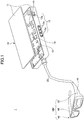
- FIG. 1 is a diagram illustrating a retinal scanning head-mounted display.
- the retinal scanning head-mounted display 1 is a retinal scanning head-mounted display that utilizes a Maxwellian view.
- a Maxwellian view is a method of causing a user to visually recognize an image represented by image data without being affected by a function of a crystalline lens of the user by projecting image light based on the image data (which may also be referred to as an image light beam, hereinafter) on a retina after the image light is converged once at a center of a pupil.
- the retinal head-mounted display 1 is provided with a controller 10; a transmission cable 20; and a head mount unit HM.
- the controller 10 has a size such that the controller 10 is capable of being carried by being accommodated in a pocket, etc., of user's clothes.
- the controller 10 emits, as image light, a laser beam with intensity according to an image signal. Details of the controller 10 are described below.
- the transmission cable 20 transmits the image light emitted from the controller 10 to an optical scanner 30.
- the head mount unit HM includes the optical scanner 30; an eyeglass frame 40; and an image capturing unit 50.
- the optical scanner 30 projects an image indicated by image light onto a retina of a user by scanning the image light transmitted by the transmission cable 20 to irradiate the image light onto an eyeball (retina) of the user.
- the eyeglass frame 40 is configured so that it can be attached to a head of a user.
- the image capturing unit 50 is provided with a camera, etc.
- the optical scanner 30 and the image capturing unit 50 are included in the eyeglass frame 40.
- the image light is light generated based on information that can be a source of an image to be projected onto a user's retina by the optical scanner 30.
- the information that can be the source of the image may be a symbol, such as a character and a number, or may be an image.
- the controller 10 is provided with a case 11 that can be operated by a user; an electronic circuit board 12; and an operation unit 13.
- the operation unit 13 is provided on a side surface of the case 11.
- the operation unit 13 is provided with, for example, a power supply switch 13a; a phase switch 13b; an adjuster 13c for adjusting a size of an image.
- the electronic circuit board 12 is accommodated inside the case 11.
- a plurality of IC chips 14 for implementing the operation of the controller 10 is mounted on the electronic circuit board 12.
- the optical scanning controller 10 is provided with an external input terminal 15 (cf. FIG. 2 ).
- the controller 10 receives content information, etc., transmitted from an external device, such as a personal computer, which is not depicted, through the external input terminal 15.
- the content information is information to be projected onto a retina of a user, such as a character, an image, and video.
- the content information is, for example, a text file, an image file, a video file, etc., used for a personal computer.
- the controller 10 is configured so that image signals can be input from two systems.
- One of the image signals from the two systems is an image signal input from the image capturing unit 50, and the other one of the image signals from the two systems is an image signal input from an external device.
- the operation unit 13 is provided with a selection switch (not depicted) for allowing a user to select whether to project the image signal from the image capturing unit 50 onto a retina or to project the image signal from the external device onto the retina.
- a selection switch (not depicted) for allowing a user to select whether to project the image signal from the image capturing unit 50 onto a retina or to project the image signal from the external device onto the retina.
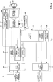
- FIG. 2 is a second diagram illustrating the retinal scanning head-mounted display 1 according to the embodiment.
- a configuration of the head mount unit HM, and circuit blocks implemented on the electronic circuit board 12 are illustrated.
- the head mount unit HM is described.
- the head mount unit HM is provided with the optical scanner 30; a Micro Electro Mechanical System (MEMS) interface 42; the image capturing unit 50; and an optical system 60.
- MEMS Micro Electro Mechanical System
- the optical scanner 30 is, for example, a Micro Electro Mechanical System (MEMS) mirror.
- the optical scanner 30 is, for example, arranged at a temple 41 of the eyeglass frame 40.
- the optical scanner 30 scans image light emitted from a laser module 125, which is described below, in a horizontal direction and in a vertical direction based on a drive control signal.
- the drive control signal is output from an MEMS driver 123, which is described below.
- a method e.g., raster scan
- an image is displayed by scanning light at high speed from upper left to lower right in a region onto which the image is to be projected.
- the image light emitted from the optical scanner 30 is converged by the optical system 60 to be projected onto the retina G1.
- the optical system 60 is arranged in a lens part of the eyeglass frame 40.
- the MEMS interface 42 detects a motion (deflection angle) of the optical scanner 30 (MEMS mirror) and outputs motion information corresponding to the tilt of the optical scanner 30 to a main controller 121, which is described below.
- the MEMS interface 42 according to the embodiment may be provided with a temperature sensor (not depicted), and the MEMS interface 42 may detect a temperature of the optical scanner 30 to output temperature information to the main controller 121.
- the image capturing unit 50 includes an image capturing device 51 and a camera interface 52.
- the image capturing device 51 is a camera including an image sensor, such as a complementary metal-oxide-semiconductor (CMOS) image sensor.
- CMOS complementary metal-oxide-semiconductor
- the image capturing device 51 outputs, to the camera interface 52, the image data captured in a format determined by a specification, etc., of the image capturing device 51.
- the camera interface 52 outputs the image data output from the image capturing device 51 to the main controller 121, which is described below.
- the camera interface 52 according to the embodiment converts the image data received from the image capturing device 51 into image data with a format suitable for transmission by the transmission cable 20, and, then, the camera interface 52 outputs the converted image data to the main controller 121.
- the camera interface 52 generates a plurality of voltages from a power supply voltage supplied to the camera interface 52 to provide the plurality of voltages to the image capturing device 51. Furthermore, upon detecting that an operation to indicate zoom-in or zoom-out of the captured image is made at the operation unit 13 of the controller 10, the camera interface 52 according to the embodiment applies, to the image data output from the image capturing device 51, image processing that corresponds to the operation.
- the main controller 121 a laser controller 122; the MEMS driver 123; a laser driver 124; and the laser module (light source) 125 are implemented.
- the main controller 121 is implemented by a processor, such as a central processing unit (CPU), a random access memory (RAM), a read-only memory (ROM), etc.
- Image data from two systems i.e., image data output from the image capturing unit 50 and content information (image data) output from an external device through the external input terminal 15, are input to the main controller 121.
- the main controller 121 executes processing of the input image signal and drive control of the optical scanner 30 (MEMS mirror).
- the main controller 121 controls driving of the optical scanner 30 (MEMS mirror) and emission of image light from the laser module 125.
- the main controller 121 outputs, to the MEMS driver 123, a drive control signal for controlling driving of the optical scanner 30.
- the MEMS driver 123 outputs the received drive control signal to the optical scanner 30.
- the main controller 121 outputs the input image data to the laser driver 124.
- the laser driver 124 generates, based on the image signal, an emission control signal to control turning on and turning off the light source (the laser module) 125, and the laser driver 124 outputs the generated emission control signal to the laser module 125.
- the laser controller 122 is implemented by a processor, such as a CPU; a RAM; a ROM, etc. Upon detecting that a signal from the operation unit 13 to turn on the power supply, a zoom-in signal, or a zoom-out signal is input, the laser controller 122 outputs a control signal corresponding to the input signal to the laser module 125. Note that, upon receiving, at the selection switch of the operation unit 13, a selection of specific image data of the data from the two systems, the laser controller 122 according to the embodiment outputs a control signal to the laser module 125 in accordance with the selection.
- the laser module 125 In response to receiving an indication from the main controller 121, the laser module 125 outputs (emits), for example, a light beam L with one or more wavelengths to the optical scanner 30.
- the light beam L is the image light beam for projecting an image onto the retina G1 of the user's eye ball G. Note that the light beam L emitted from the laser module 125 is transmitted to the optical scanner 30 through the transmission cable 20.
- the laser module 125 emits a read laser beam (wavelength: approximately from 610 nm to 660 nm), a green laser beam (wavelength: approximately from 515 nm to 540 nm), and a blue laser beam (wavelength: approximately from 440 nm to 480 nm).
- the laser beams in colors of read, green, and blue, respectively, are emitted.
- the laser module 125 according to the embodiment is implemented, for example, by a light source in which laser diode chips in RGB (read, green, and blue), respectively, a device for combining the three colors, and a micro collimator lens are integrated.
- the laser module 125 is provided with a light amount sensor 125a and a temperature sensor 125b.
- the light amount sensor 125a detects a light amount of each laser diode of the laser module 125 and outputs the detected light amount information to the laser controller 122.
- the temperature sensor 125b detects a temperature of each laser diode of the laser module 125 and outputs the detected temperature information to the laser controller 122.
- the laser controller 122 generates a signal for controlling the light amount of each leaser diode of the laser module 125 based on the light amount information obtained from the light amount sensor 125a, and the laser controller 122 outputs the generated signal to the laser module 125.
- FIG. 3 is a diagram illustrating functions of the camera interface 52.
- An operation of the image capturing device 51 according to the embodiment is controlled by a control signal S1 output from the camera interface 52.
- the image capturing device 51 may be indicated to start capturing an image by a control signal S1.
- the start of capturing the image may be indicated, in response to detecting that a selection switch of the operation unit 13 is operated to select image data captured by the image capturing device 51.
- the controller 10 reports, to the camera interface 52, that the image capturing device 51 is indicated to start capturing the image by a control signal S11.
- the camera interface 52 may transmit, to the image capturing device 51, the control signal S1 for indicating to start capturing the image.
- the image capturing device 51 Upon receiving the indication to start capturing the image, the image capturing device 51 starts capturing the image, and the image capturing device 51 transmits the captured image data to the camera interface 52. At this time, the image data S2 output from the image capturing device 51 is transmitted to the camera interface 52 in accordance with a Mobile Industry Processor Interface (MIPI) standard, which is one of interface standards with a camera, etc., included in a mobile terminal. Furthermore, image data S2 output from the image capturing device 51 is transmitted to the camera interface 52 by parallel communication.
- MIPI Mobile Industry Processor Interface
- voltages V1 through V4 which are the power sources, are supplied to the image capturing device 51 according to the embodiment through the camera interface 52.
- the camera interface 52 transmits, to the controller 10, image data S2 received from the image capturing device 51, as the image data S21 conforming to the Hi-Definition Multimedia Interface (HDMI: registered trademark) standard, which is a standard of a communication interface for transmitting video and/or audio.
- HDMI Hi-Definition Multimedia Interface
- the format converter 521 converts image data conforming to the MIPI standard or image data transmitted by the parallel communication into the image data conforming to the HDMI standard.
- the format conforming to the MIPI standard or the format conforming to the parallel transmission scheme is referred to as a first format
- the format conforming to the HDMI standard is referred to as a second format.
- the camera interface 52 receives, from the controller 10, the control signal S11 for transmitting an indication to the image capturing device 51.
- the indication to the image capturing device 51 includes, for example, an indication to start capturing an image, or an indication to zoom in or zoom out.
- the controller 10 supplies, to the camera interface 52, a voltage V31, which can be a power source of the camera interface 52.
- the camera interface 52 according to the embodiment is provided with the format converter 521; an image processor 522; and a voltage generator 523.
- the functions of the format converter 521 and the image processor 522 may be implemented by a field-programmable gate array (FPGA); and the function of the voltage generator 523 may be implemented by a known step-up/down circuit, etc.
- FPGA field-programmable gate array
- the format converter 521 converts the image data S2 transmitted from the image capturing device 51 into the image data S21 conforming to the standard, which is for transmitting data to the controller 10.
- the image processor 522 applies image processing to the image data S2 prior to the conversion by the format converter 521.
- the voltage generator 523 generates a voltage supplied to the image capturing device 51.
- FIG. 4 is a diagram illustrating the format converter 521.
- the format converter 521 is provided with an HDMI transmitter 531; a MIPI/parallel converter 532; and a bit extension unit 533.
- the HDMI transmitter 531 converts the image data input as 8-bit input signals into the image data S21 conforming to the HDMI standard. Specifically, the HDMI transmitter 531 according to the embodiment receives R-component image data, G-component image data, and B-component image data of the RGB image data as the 8-bit input signals and converts the received signals into the image data conforming to the HDMI standard.
- the MIPI/parallel converter 532 In response to detecting that the image data S2 is transmitted in accordance with the MIPI standard, the MIPI/parallel converter 532 converts each of the R component, the G component, and the B component of the image data S2 into an 8-bit input signal.
- the bit extension unit 533 In response to detecting that the image data S2 is transmitted by the parallel communication, the bit extension unit 533 extends each of the R-component, the G-component, and the B-component of the image data S2 to an 8-bit signal.
- the bit extension unit 533 extends these signals to 8-bit signals for the respective components.
- the image (video) data and the audio data captured by the image capturing device 51 can be transmitted to the controller 10 as a digital signal.
- noise can be reduced and degradation in image quality can be suppressed during transmission of the image data from the image capturing unit 50 to the controller 10 through the transmission cable 20.
- the digitally modulated image data S21 is transmitted, so that there is no need to provide a restriction on a length of the transmission path.
- the embodiment there is no need to provide a restriction on the length of the transmission cable 20, which couples the head mount unit HM, in which the image capturing unit 50 is installed, to the controller 10.
- the length of the transmission cable 20 can be sufficiently extended, so that a motion of the user is not to be interfered with.
- wearability of the retinal scanning head-mounted display 1 can be enhanced.
- the number of the signal lines (pins) required for transmission of the image data can be reduced. Consequently, for example, compared to a case where the image data S2 is transmitted to the controller 10 by the parallel transmission, the diameter of the transmission cable 20 can be reduced when the image data is transmitted in accordance with the HDMI standard.
- the stiffness of the transmission cable 20 is reduced, and a motion of a user becomes less restricted.
- wearability of the retinal scanning head-mounted display 1 can be enhanced.
- the image processor 522 In response to receiving, from the controller 10, an indication to zoom in or zoom out, the image processor 522 according to the embodiment applies the corresponding image processing to the image data S2 received from the image capturing device 51. Details of the image processor 522 are described below.
- the voltage generator 523 generates the voltages V1 through V4 from the voltage V 31 supplied from the controller 10 and supplies the voltages V1 through V4 to the image capturing device 51.
- the voltages V1 through V4 that can be the power source of the image capturing device 51 are the voltages with predetermined values according to a specification of the image capturing device 51. Each of the voltages V1 through V4 can take a plurality of values.
- an absolute value of a voltage that is supplied, as a power source, to a motor, etc., for driving a mechanism for capturing an image is different from an absolute value of a voltage that is supplied, as a power source, to an integrated circuit (IC) chip, etc., for executing various types of control in the image capturing device 51. Accordingly, in the camera interface 52 according to the embodiment, a voltage with a value that is required in the image capturing device 51 is generated and the generated voltage is supplied to the image capturing device 51.
- the voltage generator 523 may generate a voltage with a value that is required by the voltage generator 523 itself, other than the voltages V1 through V4 to be supplied to the image capturing device 51. Furthermore, the values of the voltages supplied to the image capturing device 51 may include a value other than the values of the voltages V1 through V4.
- the voltages supplied to the image capturing device 51 are generated and supplied by the camera interface 52 located in the vicinity of the image capturing device 51. Accordingly, in the embodiment, compared to a case where the voltages are supplied from the controller 10, which is physically more separated from the image capturing device 51 than the camera interface 52, a voltage drop (loss) caused by a power supply line can be suppressed. In other words, in the embodiment, the voltages that can be the power sources of the image capturing device 51 are generated by the camera interface 52 located in the vicinity of the image capturing device 51, so that the voltage loss due to the resistance of the power supply line that couples the image capturing device 51 to the camera interface 52 can be reduced.
- FIG. 5 is a flowchart illustrating a process executed by the camera interface 52.
- the camera interface 52 receives image data from the image capturing device 51 (step S501). Subsequently, in the camera interface 52, the image processor 522 determines whether an indication to zoom in or zoom out is received (step S502).
- the image processor 522 upon receiving the above-described indication, applies the image processing corresponding to the indication to the received image data (step S503).
- the format converter 521 converts the received image data into the image data S21 conforming to the HDMI standard to output the image data S21 to the controller 10 (step S504) and terminates the process.
- FIGS. 6A and 6B are diagrams illustrating the image processing by the image processor 522.
- FIGS. 6A and 6B illustrate the image processing when, at the operation unit 13 of the controller 10, an operation is made that is for indicating to zoom in.
- FIG. 6A illustrates an image prior to applying the image processing
- FIG. 6B illustrates an image after applying the image processing.
- FIG. 6A illustrates an image 601 where neither the indication to zoom in nor the indication to zoom out is received.
- the image 601 is an image with x pixels by y pixels, and the center point is the point P.
- the image 601A is an image with x pixels by y pixels, with the point P as the center. Namely, the image 601A is an image with the size that is the same as the size of the image 601 prior to applying the image processing.
- the image 601A includes a region 602 and a black region 603 that masks the periphery of the region 602.
- the region 602 is a region with x/2 pixels by y/2 pixels, with the point P as the center.
- the image processor 522 Upon receiving an indication to zoom in with the magnification of two, for example, through the control signal S11, the image processor 522 according to the embodiment creates the image 601A by masking, with a single black color, the region 603 that is outside the region 602 with x/2 pixels by y/2 pixels having the point P as the center to obtain the black region 603, in the image data of the image 601 obtained from the image capturing device 51.
- the image processor 522 passes the image 601A to the format converter 521.
- the format converter 521 converts the image data of the image 601A into image data conforming to the HDMI standard and transmits the converted image data to the controller 10.
- the controller 10 By scanning the image data of the image 601A, the controller 10 projects, onto a user's retina, the image obtained by zooming in the image 601 with the magnification of two. Note that the controller 10 executes control of the optical scanner 30, which control corresponds to the indication to zoom in with the magnification of two.
- the process is described that is executed by the image processor 522 upon receiving the indication to zoom in.
- the image processor 522 may execute the process opposite to the process corresponding to the indication to zoom in.
- the black region 603 may be deleted from the image 601A.
- image processing corresponding to the indication to zoom out can be applied to the image to which image processing has been applied once in accordance with the indication to zoom in. Additionally, in the embodiment, the image processing corresponding to the indication to zoom out may not be applied to an image to which image processing corresponding to an indication to zoom in has not been applied.
- the reason for providing, in the image processing corresponding to zoom-in in the embodiment, the black region 603 is described by referring to FIG. 7 .
- FIGS. 7A through 7C are diagrams illustrating the image processing by the image processor 522.
- FIG. 7A is a diagram illustrating the image processing corresponding to zoom-in by a generic projector.
- FIG. 7B is a first diagram illustrating the image processing corresponding to zoom-in according to the embodiment.
- FIG. 7C is a second diagram illustrating the image processing corresponding to zoom-in according to the embodiment.
- the projection area is an area scanned by the optical scanner 30.
- the image of the region 702 is projected onto the entire projection area 710 because, in the example of FIG. 7A , the size and the shape of the projection area 710 match the size and the shape of the image projected onto the projection area 170.
- the retina as a projection surface
- the retina is a curved surface instead of a planar surface because the eyeball is spherical.
- a projection surface is scanned in a trapezoidal shape, so that the projection surface matches the curved surface of the retina.
- the shape of the projection area 710A is a trapezoidal shape, as illustrated in FIG. 7B and FIG. 7C .
- an image other than the image to be actually focused on is to be projected onto the user's retina, which is not preferable.
- the image processor 522 converts the image 701 into the image 701A, which is obtained by converting a region other than the region 702 to be projected onto the projection area 710A into a black region 704 by masking the region with a single black color.
- the optical scanner 30 controls the laser diode so as not to emit light for an image in a black color. Namely, the optical scanner 30 turns off the laser diode for the region inside the black region 704 within the image 701A.
- the image 701A is projected by the retinal scanning head-mounted display according to the embodiment, the image other than the image in the region 702 is not projected onto the projection area 710A.
- the problem is such that, when a projection surface is a curved surface, such as a retina, and when an image is to be magnified and projected, an image other than the image desired to be focused on by a user is also magnified and projected.
- a projection surface is a curved surface, such as a retina
- an image other than the image desired to be focused on by a user is also magnified and projected.
- only the image in a region desired to be focused on by the user can be magnified and projected.
- the image processor 522 upon receiving an indication to zoom in, executes the above-described image processing prior to converting, by the camera interface 52, the format of the image data S2.
- the embodiment is applied to the retinal scanning head-mounted display.
- the embodiment is not limited to this.
- the embodiment may be applied to any projector, provided that an optical scanner 30 and an image capturing unit 50 are coupled to a controller 10 through a transmission cable 20 in the projector.
- optical scanning head-mounted display and the retinal scanning head-mounted display are described above by the embodiment.
- the optical scanning head-mounted display and the retinal scanning head-mounted display according to the present invention are not limited to the above-described embodiment, and various modifications and improvements may be made within the scope of the present invention.
- the present application is based on and claims the benefit of priority of Japanese Priority Application No. 2016-192102, filed on September 29, 2016 , the entire contents of which are hereby incorporated herein by reference.
Landscapes
- Engineering & Computer Science (AREA)
- Multimedia (AREA)
- Signal Processing (AREA)
- Physics & Mathematics (AREA)
- Optics & Photonics (AREA)
- General Physics & Mathematics (AREA)
- Mechanical Optical Scanning Systems (AREA)
- Mechanical Light Control Or Optical Switches (AREA)
- Control Of Indicators Other Than Cathode Ray Tubes (AREA)
- Controls And Circuits For Display Device (AREA)
Abstract
Description
- The present disclosure relates to an optical scanning head-mounted display and a retinal scanning head-mounted display.
- In recent years, a head-mounted display device has been known, which is to be attached to a head. In the display device, a camera for capturing an image of an outside view is provided in an image display unit to be attached to the head; the image of the outside view in a direction in which a user faces is captured by the camera; and the captured content is transmitted from the image display unit to a controller through a wire.
- Further, in the display device, the controller generates a signal for controlling an optical image display unit included in the image display unit. The image display unit controls the optical image display unit based on the signal, so that the image of the content captured by the camera is to be displayed.
- [Patent Document 1] Japanese Unexamined Patent Publication No.
2016-75735 - In the above-described technique, the image data of the image captured by the camera is transmitted to the controller through the wire. However, deterioration of the image by the transmission is not considered.
- There is a need for an optical scanning head-mounted display and a retinal scanning head-mounted display that can suppress deterioration of an image during transmission of image data.
- According to an aspect of the present disclosure, there is provided an optical scanning head-mounted display including a head mount unit (HM) including a light source (125) that emits a light beam; an optical scanner (30) that scans the light beam to irradiate the light beam onto a projection plane; an image capturing device (51) that outputs image data of a captured image as the image data in a first format; and an interface (52) that converts the image data in the first format obtained from the image capturing device (51) into the image data in a second format and outputs the image data in the second format; a transmission cable (20) that transmits the image data in the second format; and a controller (10) that receives the image data in the second format through the transmission cable (20) and controls the emission of the light beam from the light source (125) based on the image data in the second format.
- According to another aspect of the present disclosure, there is provided a retinal scanning head-mounted display including a head mount unit (HM) including a light source (125) that emits a light beam, an optical scanner (30) that scans the light beam to irradiate the light beam onto a retina of a user, an image capturing device (51) that outputs image data of a captured image as the image data in a first format, and an interface (52) that converts the image data in the first format obtained from the image capturing device into the image data in a second format and outputs the image data in the second format; a transmission cable (20) that transmits the image data in the second format; and a controller (10) that receives the image data in the second format through the transmission cable (20) and controls the emission of the light beam from the light source (125) based on the image data in the second format.
- Note that the reference numerals in the above-described parentheses are attached so as to facilitate understanding, the reference numerals in the above-described parentheses are merely examples, and the present invention is not limited to the depicted embodiments.
- According to the disclosed technique, deterioration in quality of the image can be suppressed during transmission of the image data.
-
-
FIG. 1 is a first diagram illustrating a retinal scanning head-mounted display; -
FIG. 2 is a second diagram illustrating the retinal scanning head-mounted display; -
FIG. 3 is a diagram illustrating functions of a camera interface; -
FIG. 4 is a diagram illustrating a format converter; -
FIG. 5 is a flowchart illustrating a process of the camera interface; -
FIG. 6A is a diagram illustrating an image process by an image processor; -
FIG. 6B is a diagram illustrating the image process by the image processor; -
FIG. 7A is a diagram illustrating the image process by the image processor; -
FIG. 7B is a diagram illustrating the image process by the image processor; and -
FIG. 7C is a diagram illustrating the image process by the image processor. - In an embodiment, a head mount unit to be attached to a user's head is provided with an interface for converting image data captured by an image capturing device installed in a head mount unit into the image data suitable for transmission to a controller through a cable.
- In the following, the embodiment is described by referring to the drawings.
FIG. 1 is a diagram illustrating a retinal scanning head-mounted display. - The retinal scanning head-mounted
display 1 according to the embodiment is a retinal scanning head-mounted display that utilizes a Maxwellian view. A Maxwellian view is a method of causing a user to visually recognize an image represented by image data without being affected by a function of a crystalline lens of the user by projecting image light based on the image data (which may also be referred to as an image light beam, hereinafter) on a retina after the image light is converged once at a center of a pupil. - An overall configuration of the retinal scanning head-mounted
display 1 is described. As illustrated inFIG. 1 , the retinal head-mounteddisplay 1 is provided with acontroller 10; atransmission cable 20; and a head mount unit HM. - The
controller 10 has a size such that thecontroller 10 is capable of being carried by being accommodated in a pocket, etc., of user's clothes. Thecontroller 10 emits, as image light, a laser beam with intensity according to an image signal. Details of thecontroller 10 are described below. - The
transmission cable 20 transmits the image light emitted from thecontroller 10 to anoptical scanner 30. - The head mount unit HM includes the
optical scanner 30; aneyeglass frame 40; and animage capturing unit 50. - The
optical scanner 30 projects an image indicated by image light onto a retina of a user by scanning the image light transmitted by thetransmission cable 20 to irradiate the image light onto an eyeball (retina) of the user. - The
eyeglass frame 40 is configured so that it can be attached to a head of a user. Theimage capturing unit 50 is provided with a camera, etc. Theoptical scanner 30 and theimage capturing unit 50 are included in theeyeglass frame 40. - Here, the image light is light generated based on information that can be a source of an image to be projected onto a user's retina by the
optical scanner 30. The information that can be the source of the image may be a symbol, such as a character and a number, or may be an image. - The
controller 10 is provided with acase 11 that can be operated by a user; anelectronic circuit board 12; and anoperation unit 13. Theoperation unit 13 is provided on a side surface of thecase 11. Theoperation unit 13 is provided with, for example, apower supply switch 13a; aphase switch 13b; anadjuster 13c for adjusting a size of an image. Theelectronic circuit board 12 is accommodated inside thecase 11. A plurality ofIC chips 14 for implementing the operation of thecontroller 10 is mounted on theelectronic circuit board 12. - The
optical scanning controller 10 is provided with an external input terminal 15 (cf.FIG. 2 ). Thecontroller 10 receives content information, etc., transmitted from an external device, such as a personal computer, which is not depicted, through theexternal input terminal 15. Note that the content information is information to be projected onto a retina of a user, such as a character, an image, and video. Specifically, the content information is, for example, a text file, an image file, a video file, etc., used for a personal computer. - The
controller 10 according to the embodiment is configured so that image signals can be input from two systems. One of the image signals from the two systems is an image signal input from theimage capturing unit 50, and the other one of the image signals from the two systems is an image signal input from an external device. - From the above-described point, the
operation unit 13 according to the embodiment is provided with a selection switch (not depicted) for allowing a user to select whether to project the image signal from theimage capturing unit 50 onto a retina or to project the image signal from the external device onto the retina. -
FIG. 2 is a second diagram illustrating the retinal scanning head-mounteddisplay 1 according to the embodiment. InFIG. 2 , a configuration of the head mount unit HM, and circuit blocks implemented on theelectronic circuit board 12 are illustrated. - First, the head mount unit HM is described.
- The head mount unit HM according to the embodiment is provided with the
optical scanner 30; a Micro Electro Mechanical System (MEMS)interface 42; theimage capturing unit 50; and anoptical system 60. - The
optical scanner 30 is, for example, a Micro Electro Mechanical System (MEMS) mirror. Theoptical scanner 30 is, for example, arranged at atemple 41 of theeyeglass frame 40. Theoptical scanner 30 scans image light emitted from alaser module 125, which is described below, in a horizontal direction and in a vertical direction based on a drive control signal. The drive control signal is output from anMEMS driver 123, which is described below. - Furthermore, as a method of projecting an image onto a retina G1 of an eye ball G by scanning the image light, a method (e.g., raster scan) can be implemented such that an image is displayed by scanning light at high speed from upper left to lower right in a region onto which the image is to be projected.
- The image light emitted from the
optical scanner 30 is converged by theoptical system 60 to be projected onto the retina G1. Note that theoptical system 60 is arranged in a lens part of theeyeglass frame 40. - The
MEMS interface 42 detects a motion (deflection angle) of the optical scanner 30 (MEMS mirror) and outputs motion information corresponding to the tilt of theoptical scanner 30 to amain controller 121, which is described below. Note that theMEMS interface 42 according to the embodiment may be provided with a temperature sensor (not depicted), and theMEMS interface 42 may detect a temperature of theoptical scanner 30 to output temperature information to themain controller 121. - The
image capturing unit 50 according to the embodiment includes animage capturing device 51 and acamera interface 52. - The
image capturing device 51 is a camera including an image sensor, such as a complementary metal-oxide-semiconductor (CMOS) image sensor. Theimage capturing device 51 outputs, to thecamera interface 52, the image data captured in a format determined by a specification, etc., of theimage capturing device 51. - The
camera interface 52 outputs the image data output from theimage capturing device 51 to themain controller 121, which is described below. Thecamera interface 52 according to the embodiment converts the image data received from theimage capturing device 51 into image data with a format suitable for transmission by thetransmission cable 20, and, then, thecamera interface 52 outputs the converted image data to themain controller 121. - Furthermore, the
camera interface 52 according to the embodiment generates a plurality of voltages from a power supply voltage supplied to thecamera interface 52 to provide the plurality of voltages to theimage capturing device 51. Furthermore, upon detecting that an operation to indicate zoom-in or zoom-out of the captured image is made at theoperation unit 13 of thecontroller 10, thecamera interface 52 according to the embodiment applies, to the image data output from theimage capturing device 51, image processing that corresponds to the operation. - Details of the
camera interface 52 according to the embodiment are described below. - Next, the circuit blocks of the
electronic circuit board 12 of thecontroller 10 are described. - In the
electronic circuit board 12, themain controller 121; alaser controller 122; theMEMS driver 123; alaser driver 124; and the laser module (light source) 125 are implemented. - The
main controller 121 is implemented by a processor, such as a central processing unit (CPU), a random access memory (RAM), a read-only memory (ROM), etc. Image data from two systems, i.e., image data output from theimage capturing unit 50 and content information (image data) output from an external device through theexternal input terminal 15, are input to themain controller 121. Themain controller 121 executes processing of the input image signal and drive control of the optical scanner 30 (MEMS mirror). - Furthermore, based on the motion information, the temperature information, etc., of the
optical scanner 30 obtained from theMEMS interface 42, themain controller 121 controls driving of the optical scanner 30 (MEMS mirror) and emission of image light from thelaser module 125. - Furthermore, the
main controller 121 outputs, to theMEMS driver 123, a drive control signal for controlling driving of theoptical scanner 30. TheMEMS driver 123 outputs the received drive control signal to theoptical scanner 30. - Furthermore, the
main controller 121 outputs the input image data to thelaser driver 124. Thelaser driver 124 generates, based on the image signal, an emission control signal to control turning on and turning off the light source (the laser module) 125, and thelaser driver 124 outputs the generated emission control signal to thelaser module 125. - The
laser controller 122 is implemented by a processor, such as a CPU; a RAM; a ROM, etc. Upon detecting that a signal from theoperation unit 13 to turn on the power supply, a zoom-in signal, or a zoom-out signal is input, thelaser controller 122 outputs a control signal corresponding to the input signal to thelaser module 125. Note that, upon receiving, at the selection switch of theoperation unit 13, a selection of specific image data of the data from the two systems, thelaser controller 122 according to the embodiment outputs a control signal to thelaser module 125 in accordance with the selection. - In response to receiving an indication from the
main controller 121, thelaser module 125 outputs (emits), for example, a light beam L with one or more wavelengths to theoptical scanner 30. The light beam L is the image light beam for projecting an image onto the retina G1 of the user's eye ball G. Note that the light beam L emitted from thelaser module 125 is transmitted to theoptical scanner 30 through thetransmission cable 20. - For example, the
laser module 125 emits a read laser beam (wavelength: approximately from 610 nm to 660 nm), a green laser beam (wavelength: approximately from 515 nm to 540 nm), and a blue laser beam (wavelength: approximately from 440 nm to 480 nm). The laser beams in colors of read, green, and blue, respectively, are emitted. Thelaser module 125 according to the embodiment is implemented, for example, by a light source in which laser diode chips in RGB (read, green, and blue), respectively, a device for combining the three colors, and a micro collimator lens are integrated. - Additionally, the
laser module 125 is provided with alight amount sensor 125a and atemperature sensor 125b. Thelight amount sensor 125a detects a light amount of each laser diode of thelaser module 125 and outputs the detected light amount information to thelaser controller 122. Thetemperature sensor 125b detects a temperature of each laser diode of thelaser module 125 and outputs the detected temperature information to thelaser controller 122. - The
laser controller 122 generates a signal for controlling the light amount of each leaser diode of thelaser module 125 based on the light amount information obtained from thelight amount sensor 125a, and thelaser controller 122 outputs the generated signal to thelaser module 125. - Next, by referring to
FIG. 3 , thecamera interface 52 according to the embodiment is described.FIG. 3 is a diagram illustrating functions of thecamera interface 52. - First, transmission and reception of signals and voltages between the
image capturing device 51 and thecamera interface 52 in theimage capturing unit 50 are described. - An operation of the
image capturing device 51 according to the embodiment is controlled by a control signal S1 output from thecamera interface 52. - Specifically, the
image capturing device 51 may be indicated to start capturing an image by a control signal S1. For example, in thecontroller 10, the start of capturing the image may be indicated, in response to detecting that a selection switch of theoperation unit 13 is operated to select image data captured by theimage capturing device 51. In this case, thecontroller 10 reports, to thecamera interface 52, that theimage capturing device 51 is indicated to start capturing the image by a control signal S11. Upon receiving the control signal S11, thecamera interface 52 may transmit, to theimage capturing device 51, the control signal S1 for indicating to start capturing the image. - Upon receiving the indication to start capturing the image, the
image capturing device 51 starts capturing the image, and theimage capturing device 51 transmits the captured image data to thecamera interface 52. At this time, the image data S2 output from theimage capturing device 51 is transmitted to thecamera interface 52 in accordance with a Mobile Industry Processor Interface (MIPI) standard, which is one of interface standards with a camera, etc., included in a mobile terminal. Furthermore, image data S2 output from theimage capturing device 51 is transmitted to thecamera interface 52 by parallel communication. - Furthermore, voltages V1 through V4, which are the power sources, are supplied to the
image capturing device 51 according to the embodiment through thecamera interface 52. - Next, transmission and reception of signals and voltages between the
camera interface 52 and thecontroller 10 are described. - The
camera interface 52 according to the embodiment transmits, to thecontroller 10, image data S2 received from theimage capturing device 51, as the image data S21 conforming to the Hi-Definition Multimedia Interface (HDMI: registered trademark) standard, which is a standard of a communication interface for transmitting video and/or audio. - Namely, the
format converter 521 according to the embodiment converts image data conforming to the MIPI standard or image data transmitted by the parallel communication into the image data conforming to the HDMI standard. Here, the format conforming to the MIPI standard or the format conforming to the parallel transmission scheme is referred to as a first format, and the format conforming to the HDMI standard is referred to as a second format. - Furthermore, the
camera interface 52 receives, from thecontroller 10, the control signal S11 for transmitting an indication to theimage capturing device 51. The indication to theimage capturing device 51 includes, for example, an indication to start capturing an image, or an indication to zoom in or zoom out. - Furthermore, the
controller 10 supplies, to thecamera interface 52, a voltage V31, which can be a power source of thecamera interface 52. - Next, the functions of the
camera interface 52 according to the embodiment are described. Thecamera interface 52 according to the embodiment is provided with theformat converter 521; animage processor 522; and avoltage generator 523. - In the above-described
camera interface 52, the functions of theformat converter 521 and theimage processor 522 may be implemented by a field-programmable gate array (FPGA); and the function of thevoltage generator 523 may be implemented by a known step-up/down circuit, etc. - The
format converter 521 converts the image data S2 transmitted from theimage capturing device 51 into the image data S21 conforming to the standard, which is for transmitting data to thecontroller 10. - In response to an indication from the
controller 10, theimage processor 522 applies image processing to the image data S2 prior to the conversion by theformat converter 521. - The
voltage generator 523 generates a voltage supplied to theimage capturing device 51. - In the following, each component is further described. First, the
format converter 521 is described.FIG. 4 is a diagram illustrating theformat converter 521. - The
format converter 521 according to the embodiment is provided with anHDMI transmitter 531; a MIPI/parallel converter 532; and abit extension unit 533. - The
HDMI transmitter 531 according to the embodiment converts the image data input as 8-bit input signals into the image data S21 conforming to the HDMI standard. Specifically, theHDMI transmitter 531 according to the embodiment receives R-component image data, G-component image data, and B-component image data of the RGB image data as the 8-bit input signals and converts the received signals into the image data conforming to the HDMI standard. - In response to detecting that the image data S2 is transmitted in accordance with the MIPI standard, the MIPI/
parallel converter 532 converts each of the R component, the G component, and the B component of the image data S2 into an 8-bit input signal. - In response to detecting that the image data S2 is transmitted by the parallel communication, the
bit extension unit 533 extends each of the R-component, the G-component, and the B-component of the image data S2 to an 8-bit signal. - More specifically, when the image data S2 is transmitted from the
image capturing device 51 by the parallel communication, the image data S2 is transmitted as a signal in which the R component is 5 bits, the G component is 6 bits, and the B component is 5 bits. Accordingly, thebit extension unit 533 extends these signals to 8-bit signals for the respective components. - In the embodiment, as described above, by converting the image data S2 received from the
image capturing device 51 into the image data S21 according to the HDMI standard, the image (video) data and the audio data captured by theimage capturing device 51 can be transmitted to thecontroller 10 as a digital signal. Thus, according to the embodiment, noise can be reduced and degradation in image quality can be suppressed during transmission of the image data from theimage capturing unit 50 to thecontroller 10 through thetransmission cable 20. - Furthermore, according to the HDMI standard, the digitally modulated image data S21 is transmitted, so that there is no need to provide a restriction on a length of the transmission path.
- Consequently, in the embodiment, there is no need to provide a restriction on the length of the
transmission cable 20, which couples the head mount unit HM, in which theimage capturing unit 50 is installed, to thecontroller 10. Namely, according to the embodiment, when the head mount unit HM is attached to a user's head, and when thecontroller 10 is accommodated in clothes, etc., of the user, the length of thetransmission cable 20 can be sufficiently extended, so that a motion of the user is not to be interfered with. As a result, according to the embodiment, wearability of the retinal scanning head-mounteddisplay 1 can be enhanced. - Furthermore, according to the embodiment, by converting the image data as described above, the number of the signal lines (pins) required for transmission of the image data can be reduced. Consequently, for example, compared to a case where the image data S2 is transmitted to the
controller 10 by the parallel transmission, the diameter of thetransmission cable 20 can be reduced when the image data is transmitted in accordance with the HDMI standard. - As the diameter of the
transmission cable 20 becomes smaller, the stiffness of thetransmission cable 20 is reduced, and a motion of a user becomes less restricted. Thus, according to the embodiment, wearability of the retinal scanning head-mounteddisplay 1 can be enhanced. - Next, the
image processor 522 is described. - In response to receiving, from the
controller 10, an indication to zoom in or zoom out, theimage processor 522 according to the embodiment applies the corresponding image processing to the image data S2 received from theimage capturing device 51. Details of theimage processor 522 are described below. - Next, the
voltage generator 523 is described. Thevoltage generator 523 according to the embodiment generates the voltages V1 through V4 from the voltage V 31 supplied from thecontroller 10 and supplies the voltages V1 through V4 to theimage capturing device 51. - The voltages V1 through V4 that can be the power source of the
image capturing device 51 are the voltages with predetermined values according to a specification of theimage capturing device 51. Each of the voltages V1 through V4 can take a plurality of values. - In the
image capturing device 51, for example, an absolute value of a voltage that is supplied, as a power source, to a motor, etc., for driving a mechanism for capturing an image is different from an absolute value of a voltage that is supplied, as a power source, to an integrated circuit (IC) chip, etc., for executing various types of control in theimage capturing device 51. Accordingly, in thecamera interface 52 according to the embodiment, a voltage with a value that is required in theimage capturing device 51 is generated and the generated voltage is supplied to theimage capturing device 51. - Note that the
voltage generator 523 may generate a voltage with a value that is required by thevoltage generator 523 itself, other than the voltages V1 through V4 to be supplied to theimage capturing device 51. Furthermore, the values of the voltages supplied to theimage capturing device 51 may include a value other than the values of the voltages V1 through V4. - In the embodiment, the voltages supplied to the
image capturing device 51 are generated and supplied by thecamera interface 52 located in the vicinity of theimage capturing device 51. Accordingly, in the embodiment, compared to a case where the voltages are supplied from thecontroller 10, which is physically more separated from theimage capturing device 51 than thecamera interface 52, a voltage drop (loss) caused by a power supply line can be suppressed. In other words, in the embodiment, the voltages that can be the power sources of theimage capturing device 51 are generated by thecamera interface 52 located in the vicinity of theimage capturing device 51, so that the voltage loss due to the resistance of the power supply line that couples theimage capturing device 51 to thecamera interface 52 can be reduced. - Next, by referring to
FIG. 5 , a process is described when thecamera interface 52 according to the embodiment receives the image data from theimage capturing device 51.FIG. 5 is a flowchart illustrating a process executed by thecamera interface 52. - The
camera interface 52 according to the embodiment receives image data from the image capturing device 51 (step S501). Subsequently, in thecamera interface 52, theimage processor 522 determines whether an indication to zoom in or zoom out is received (step S502). - At step S502, upon receiving the above-described indication, the
image processor 522 applies the image processing corresponding to the indication to the received image data (step S503). - Upon detecting that the above-described indication is not received at step S502, in the
camera interface 52, theformat converter 521 converts the received image data into the image data S21 conforming to the HDMI standard to output the image data S21 to the controller 10 (step S504) and terminates the process. - In the following, by referring to
FIG. 6 andFIG. 7 , the image processing by theimage processor 522 at step S503 ofFIG. 5 is described.FIGS. 6A and 6B are diagrams illustrating the image processing by theimage processor 522. -
FIGS. 6A and 6B illustrate the image processing when, at theoperation unit 13 of thecontroller 10, an operation is made that is for indicating to zoom in.FIG. 6A illustrates an image prior to applying the image processing, andFIG. 6B illustrates an image after applying the image processing. -
FIG. 6A illustrates animage 601 where neither the indication to zoom in nor the indication to zoom out is received. Here, theimage 601 is an image with x pixels by y pixels, and the center point is the point P. - When image processing corresponding to zoom-in with a magnification of, for example, two is applied to the
image 601, theimage 601 becomes theimage 601A illustrated inFIG. 6B . - The
image 601A is an image with x pixels by y pixels, with the point P as the center. Namely, theimage 601A is an image with the size that is the same as the size of theimage 601 prior to applying the image processing. - The
image 601A includes aregion 602 and ablack region 603 that masks the periphery of theregion 602. Theregion 602 is a region with x/2 pixels by y/2 pixels, with the point P as the center. - Upon receiving an indication to zoom in with the magnification of two, for example, through the control signal S11, the
image processor 522 according to the embodiment creates theimage 601A by masking, with a single black color, theregion 603 that is outside theregion 602 with x/2 pixels by y/2 pixels having the point P as the center to obtain theblack region 603, in the image data of theimage 601 obtained from theimage capturing device 51. - Then, the
image processor 522 passes theimage 601A to theformat converter 521. Theformat converter 521 converts the image data of theimage 601A into image data conforming to the HDMI standard and transmits the converted image data to thecontroller 10. - By scanning the image data of the
image 601A, thecontroller 10 projects, onto a user's retina, the image obtained by zooming in theimage 601 with the magnification of two. Note that thecontroller 10 executes control of theoptical scanner 30, which control corresponds to the indication to zoom in with the magnification of two. - In
FIG. 6 , the process is described that is executed by theimage processor 522 upon receiving the indication to zoom in. Upon receiving an indication to zoom out, theimage processor 522 according to the embodiment may execute the process opposite to the process corresponding to the indication to zoom in. - For example, when an indication to zoom out with a magnification of two is received, the
black region 603 may be deleted from theimage 601A. - Note that, in the embodiment, image processing corresponding to the indication to zoom out can be applied to the image to which image processing has been applied once in accordance with the indication to zoom in. Additionally, in the embodiment, the image processing corresponding to the indication to zoom out may not be applied to an image to which image processing corresponding to an indication to zoom in has not been applied.
- Next, the reason for providing, in the image processing corresponding to zoom-in in the embodiment, the
black region 603 is described by referring toFIG. 7 . -
FIGS. 7A through 7C are diagrams illustrating the image processing by theimage processor 522.FIG. 7A is a diagram illustrating the image processing corresponding to zoom-in by a generic projector.FIG. 7B is a first diagram illustrating the image processing corresponding to zoom-in according to the embodiment.FIG. 7C is a second diagram illustrating the image processing corresponding to zoom-in according to the embodiment. - As illustrated in
FIG. 7A , for a projector with a projection area that is a planar screen, etc., when an indication to zoom in with a magnification of two is detected for animage 701 with x pixels by y pixels having the point P1 as the center, the image, within theimage 701, of the region with x/2 pixels by y/2 pixels having the point P1 as the center may be projected onto aprojection area 710. Note that the projection area is an area scanned by theoptical scanner 30. - By projecting the image as described above, the image of the
region 702 is projected onto theentire projection area 710 because, in the example ofFIG. 7A , the size and the shape of theprojection area 710 match the size and the shape of the image projected onto the projection area 170. - In contrast, when an image is irradiated onto a retina of a human, as in the embodiment, the retina, as a projection surface, is a curved surface instead of a planar surface because the eyeball is spherical. For this reason, in the embodiment, a projection surface is scanned in a trapezoidal shape, so that the projection surface matches the curved surface of the retina. Accordingly, in the embodiment, the shape of the
projection area 710A is a trapezoidal shape, as illustrated inFIG. 7B and FIG. 7C . - Thus, in the embodiment, as illustrated in
FIG. 7B , even if an attempt is made to project, within theimage 701, only the image in theregion 702 with x/2 pixels by y/2 pixels having the point P1 as the center onto theprojection area 710A, the image in aregion 703 within theimage 701 is actually projected. - In this case, an image other than the image to be actually focused on is to be projected onto the user's retina, which is not preferable.
- Thus, as illustrated in
FIG. 7C , theimage processor 522 according to the embodiment converts theimage 701 into theimage 701A, which is obtained by converting a region other than theregion 702 to be projected onto theprojection area 710A into ablack region 704 by masking the region with a single black color. - In the embodiment, the
optical scanner 30 controls the laser diode so as not to emit light for an image in a black color. Namely, theoptical scanner 30 turns off the laser diode for the region inside theblack region 704 within theimage 701A. - Consequently, when the
image 701A is projected by the retinal scanning head-mounted display according to the embodiment, the image other than the image in theregion 702 is not projected onto theprojection area 710A. - Thus, according to the embodiment, the following problem can be solved. Namely, the problem is such that, when a projection surface is a curved surface, such as a retina, and when an image is to be magnified and projected, an image other than the image desired to be focused on by a user is also magnified and projected. In short, according to the embodiment, only the image in a region desired to be focused on by the user can be magnified and projected.
- Furthermore, in the embodiment, upon receiving an indication to zoom in, the
image processor 522 executes the above-described image processing prior to converting, by thecamera interface 52, the format of the image data S2. - According to the embodiment, it is not necessary to execute, by the
controller 10, image processing corresponding to an indication to zoom in, and only an image in a region desired to be focused on by a user can be magnified and projected by the above-described process. Consequently, a processing load on thecontroller 10 can be reduced. - Note that, in the description above, it is assumed that the embodiment is applied to the retinal scanning head-mounted display. However, the embodiment is not limited to this. The embodiment may be applied to any projector, provided that an
optical scanner 30 and animage capturing unit 50 are coupled to acontroller 10 through atransmission cable 20 in the projector. - The optical scanning head-mounted display and the retinal scanning head-mounted display are described above by the embodiment. However, the optical scanning head-mounted display and the retinal scanning head-mounted display according to the present invention are not limited to the above-described embodiment, and various modifications and improvements may be made within the scope of the present invention. The present application is based on and claims the benefit of priority of Japanese Priority Application No.
2016-192102, filed on September 29, 2016
Claims (6)
- An optical scanning head-mounted display comprising:a head mount unit including
a light source that emits a light beam,
an optical scanner that scans the light beam to irradiate the light beam onto a projection plane,
an image capturing device that outputs image data of a captured image as the image data in a first format, and
an interface that converts the image data in the first format obtained from the image capturing device into the image data in a second format and outputs the image data in the second format;a transmission cable that transmits the image data in the second format; anda controller that receives the image data in the second format through the transmission cable and controls the emission of the light beam from the light source based on the image data in the second format. - The optical scanning head-mounted display according to claim 1, wherein the first format is a format conforming to a Mobile Industry Processor Interface, MIPI, standard or a format conforming to a parallel communication scheme, and
wherein the second format is a format conforming to a Hi-Definition Multimedia Interface, HDMI, standard. - The optical scanning head-mounted display according to claim 1 or claim 2, wherein the interface is provided with an image processor that applies image processing to the image data in the first format, and
wherein, upon receiving, by the controller, an operation for indicating to zoom in, the image processor changes a color of a region other then a region to be zoomed in into a black color in the image represented by the image data in the first format and outputs the image data in the first format to the interface. - The optical scanning head-mounted display according to any one of claims 1 through 3, wherein the interface is provided with a voltage generator that receives supply of a voltage with a predetermined value from the controller through the transmission cable to generate a plurality of voltages with a respective plurality of values to be supplied to the image capturing device.
- The optical scanning head-mounted display according to any one of claims 1 through 4, wherein the optical scanner irradiates the light beam onto a retina of a user.
- A retinal scanning head-mounted display comprising:a head mount unit including
a light source that emits a light beam,
an optical scanner that scans the light beam to irradiate the light beam onto a retina of a user,
an image capturing device that outputs image data of a captured image as the image data in a first format, and
an interface that converts the image data in the first format obtained from the image capturing device into the image data in a second format and outputs the image data in the second format;a transmission cable that transmits the image data in the second format; anda controller that receives the image data in the second format through the transmission cable and controls the emission of the light beam from the light source based on the image data in the second format.
Applications Claiming Priority (1)
| Application Number | Priority Date | Filing Date | Title |
|---|---|---|---|
| JP2016192102A JP6882659B2 (en) | 2016-09-29 | 2016-09-29 | Optical scanning head-mounted display and retinal scanning head-mounted display |
Publications (1)
| Publication Number | Publication Date |
|---|---|
| EP3301499A1 true EP3301499A1 (en) | 2018-04-04 |
Family
ID=59974178
Family Applications (1)
| Application Number | Title | Priority Date | Filing Date |
|---|---|---|---|
| EP17193331.0A Withdrawn EP3301499A1 (en) | 2016-09-29 | 2017-09-26 | Optical scanning head-mounted display and retinal scanning head-mounted display |
Country Status (4)
| Country | Link |
|---|---|
| US (1) | US10257478B2 (en) |
| EP (1) | EP3301499A1 (en) |
| JP (1) | JP6882659B2 (en) |
| CN (1) | CN107884928A (en) |
Families Citing this family (2)
| Publication number | Priority date | Publication date | Assignee | Title |
|---|---|---|---|---|
| CN112306444A (en) * | 2020-11-23 | 2021-02-02 | 青岛海信移动通信技术股份有限公司 | Mobile terminal and projection method thereof |
| US20230290318A1 (en) * | 2022-03-11 | 2023-09-14 | Medicapture, Inc. | Power-optimized monitor |
Citations (9)
| Publication number | Priority date | Publication date | Assignee | Title |
|---|---|---|---|---|
| US5742264A (en) * | 1995-01-24 | 1998-04-21 | Matsushita Electric Industrial Co., Ltd. | Head-mounted display |
| EP1064783A1 (en) * | 1998-03-25 | 2001-01-03 | W. Stephen G. Mann | Wearable camera system with viewfinder means |
| JP2008310130A (en) * | 2007-06-15 | 2008-12-25 | Konica Minolta Holdings Inc | Control unit and head-mounted display device |
| JP2011076503A (en) * | 2009-09-30 | 2011-04-14 | Brother Industries Ltd | Head mounted display |
| WO2015092968A1 (en) * | 2013-12-19 | 2015-06-25 | Sony Corporation | Head-mounted display device and image display method |
| CN104883527A (en) * | 2015-06-04 | 2015-09-02 | 段然 | Method for converting MIPI interface into HDMI interface and application system thereof |
| WO2015134733A1 (en) * | 2014-03-07 | 2015-09-11 | Aguren Jerry G | Stereo 3d head mounted display applied as a low vision aid |
| JP2016075735A (en) | 2014-10-03 | 2016-05-12 | セイコーエプソン株式会社 | Head-mounted display device, control method therefor, and computer program |
| WO2017183445A1 (en) * | 2016-04-22 | 2017-10-26 | ミツミ電機株式会社 | Display device |
Family Cites Families (8)
| Publication number | Priority date | Publication date | Assignee | Title |
|---|---|---|---|---|
| EP2950528A1 (en) * | 2006-11-07 | 2015-12-02 | Sony Corporation | Video signal transmitting device |
| CN101150727A (en) * | 2007-10-19 | 2008-03-26 | 深圳华为通信技术有限公司 | Multi-channel video signal transmission and TV wall display method, system and processing device |
| JP5045590B2 (en) * | 2008-07-23 | 2012-10-10 | 三菱電機株式会社 | Display device |
| JP2011205327A (en) * | 2010-03-25 | 2011-10-13 | Nikon Corp | Image output device |
| JP5478761B2 (en) * | 2013-07-22 | 2014-04-23 | オリンパス株式会社 | Imaging device |
| JP6137092B2 (en) * | 2014-09-12 | 2017-05-31 | ブラザー工業株式会社 | Display device, head-mounted display, display control device, display program, and display method |
| WO2016051775A1 (en) | 2014-10-03 | 2016-04-07 | Seiko Epson Corporation | Head mounted display device adapted to the environment |
| JP5861071B1 (en) * | 2014-10-14 | 2016-02-16 | パナソニックIpマネジメント株式会社 | Endoscope |
-
2016
- 2016-09-29 JP JP2016192102A patent/JP6882659B2/en active Active
-
2017
- 2017-09-13 CN CN201710823251.3A patent/CN107884928A/en active Pending
- 2017-09-14 US US15/704,478 patent/US10257478B2/en active Active
- 2017-09-26 EP EP17193331.0A patent/EP3301499A1/en not_active Withdrawn
Patent Citations (9)
| Publication number | Priority date | Publication date | Assignee | Title |
|---|---|---|---|---|
| US5742264A (en) * | 1995-01-24 | 1998-04-21 | Matsushita Electric Industrial Co., Ltd. | Head-mounted display |
| EP1064783A1 (en) * | 1998-03-25 | 2001-01-03 | W. Stephen G. Mann | Wearable camera system with viewfinder means |
| JP2008310130A (en) * | 2007-06-15 | 2008-12-25 | Konica Minolta Holdings Inc | Control unit and head-mounted display device |
| JP2011076503A (en) * | 2009-09-30 | 2011-04-14 | Brother Industries Ltd | Head mounted display |
| WO2015092968A1 (en) * | 2013-12-19 | 2015-06-25 | Sony Corporation | Head-mounted display device and image display method |
| WO2015134733A1 (en) * | 2014-03-07 | 2015-09-11 | Aguren Jerry G | Stereo 3d head mounted display applied as a low vision aid |
| JP2016075735A (en) | 2014-10-03 | 2016-05-12 | セイコーエプソン株式会社 | Head-mounted display device, control method therefor, and computer program |
| CN104883527A (en) * | 2015-06-04 | 2015-09-02 | 段然 | Method for converting MIPI interface into HDMI interface and application system thereof |
| WO2017183445A1 (en) * | 2016-04-22 | 2017-10-26 | ミツミ電機株式会社 | Display device |
Also Published As
| Publication number | Publication date |
|---|---|
| US20180091783A1 (en) | 2018-03-29 |
| JP2018054944A (en) | 2018-04-05 |
| US10257478B2 (en) | 2019-04-09 |
| JP6882659B2 (en) | 2021-06-02 |
| CN107884928A (en) | 2018-04-06 |
Similar Documents
| Publication | Publication Date | Title |
|---|---|---|
| US8794768B2 (en) | Projection display device and method of controlling the same | |
| EP3318916B1 (en) | Optical scanning head-mounted display and retinal scanning head-mounted display | |
| US10194074B2 (en) | Imaging system, warning generation device and method, imaging device and method, and program | |
| US11067806B2 (en) | Foveated display for augmented reality | |
| JP2017009986A (en) | Image projection device | |
| US10257478B2 (en) | Optical scanning head-mounted display and retinal scanning head-mounted display | |
| US10341607B2 (en) | Display device | |
| CN109791278B (en) | Optical scanning device and retina scanning type head-mounted display | |
| CN109510947B (en) | Display apparatus and control method thereof | |
| WO2018061692A1 (en) | Optical scanning control device and retina scanning projection device | |
| US10839482B2 (en) | Information processing apparatus, image display method, display system, and computer readable storage medium | |
| WO2016208266A1 (en) | Image projection device | |
| US10893186B2 (en) | Medical imaging apparatus and medical observation system | |
| US9438873B2 (en) | Projector | |
| JP7292144B2 (en) | Display control device, transmissive display device | |
| JP5076427B2 (en) | Image display device and image size changing method | |
| JP2023176702A (en) | Imaging device, information processing device, control method, program and storage medium | |
| US11372513B2 (en) | Display apparatus, control method thereof and storage medium for displaying a background image around each of a plurality of images | |
| JP2010211149A (en) | Image display | |
| JP2016115966A (en) | Display system, image display control method, and program | |
| CN112738485A (en) | Projector control method and projector | |
| JP7427912B2 (en) | Imaging device | |
| JPH08223469A (en) | Imaging device | |
| JP2009303145A (en) | Signal transmission system | |
| JP2020008806A (en) | Image projection device and image projection device control program |
Legal Events
| Date | Code | Title | Description |
|---|---|---|---|
| PUAI | Public reference made under article 153(3) epc to a published international application that has entered the european phase |
Free format text: ORIGINAL CODE: 0009012 |
|
| STAA | Information on the status of an ep patent application or granted ep patent |
Free format text: STATUS: THE APPLICATION HAS BEEN PUBLISHED |
|
| AK | Designated contracting states |
Kind code of ref document: A1 Designated state(s): AL AT BE BG CH CY CZ DE DK EE ES FI FR GB GR HR HU IE IS IT LI LT LU LV MC MK MT NL NO PL PT RO RS SE SI SK SM TR |
|
| AX | Request for extension of the european patent |
Extension state: BA ME |
|
| STAA | Information on the status of an ep patent application or granted ep patent |
Free format text: STATUS: REQUEST FOR EXAMINATION WAS MADE |
|
| 17P | Request for examination filed |
Effective date: 20180718 |
|
| RBV | Designated contracting states (corrected) |
Designated state(s): AL AT BE BG CH CY CZ DE DK EE ES FI FR GB GR HR HU IE IS IT LI LT LU LV MC MK MT NL NO PL PT RO RS SE SI SK SM TR |
|
| STAA | Information on the status of an ep patent application or granted ep patent |
Free format text: STATUS: EXAMINATION IS IN PROGRESS |
|
| 17Q | First examination report despatched |
Effective date: 20190807 |
|
| STAA | Information on the status of an ep patent application or granted ep patent |
Free format text: STATUS: THE APPLICATION IS DEEMED TO BE WITHDRAWN |
|
| 18D | Application deemed to be withdrawn |
Effective date: 20210601 |