EP3301492A1 - Wide angle lens - Google Patents
Wide angle lens Download PDFInfo
- Publication number
- EP3301492A1 EP3301492A1 EP17193634.7A EP17193634A EP3301492A1 EP 3301492 A1 EP3301492 A1 EP 3301492A1 EP 17193634 A EP17193634 A EP 17193634A EP 3301492 A1 EP3301492 A1 EP 3301492A1
- Authority
- EP
- European Patent Office
- Prior art keywords
- lens
- wide angle
- object side
- satisfy
- conditional expression
- Prior art date
- Legal status (The legal status is an assumption and is not a legal conclusion. Google has not performed a legal analysis and makes no representation as to the accuracy of the status listed.)
- Withdrawn
Links
- 239000011521 glass Substances 0.000 claims abstract description 24
- 239000004033 plastic Substances 0.000 claims abstract description 13
- 230000002093 peripheral effect Effects 0.000 claims description 17
- 230000005499 meniscus Effects 0.000 claims description 12
- 239000000853 adhesive Substances 0.000 claims description 4
- 230000001070 adhesive effect Effects 0.000 claims description 4
- 230000004075 alteration Effects 0.000 description 30
- 230000003287 optical effect Effects 0.000 description 7
- 238000012937 correction Methods 0.000 description 4
- 230000000694 effects Effects 0.000 description 3
- 238000003384 imaging method Methods 0.000 description 3
- 239000000463 material Substances 0.000 description 3
- 230000004907 flux Effects 0.000 description 2
- 229920005989 resin Polymers 0.000 description 2
- 239000011347 resin Substances 0.000 description 2
- NIXOWILDQLNWCW-UHFFFAOYSA-N acrylic acid group Chemical group C(C=C)(=O)O NIXOWILDQLNWCW-UHFFFAOYSA-N 0.000 description 1
- 230000010485 coping Effects 0.000 description 1
- 238000004554 molding of glass Methods 0.000 description 1
- 238000005498 polishing Methods 0.000 description 1
- 239000004417 polycarbonate Substances 0.000 description 1
- 229920000515 polycarbonate Polymers 0.000 description 1
- 229920005672 polyolefin resin Polymers 0.000 description 1
Images


Classifications
-
- G—PHYSICS
- G02—OPTICS
- G02B—OPTICAL ELEMENTS, SYSTEMS OR APPARATUS
- G02B7/00—Mountings, adjusting means, or light-tight connections, for optical elements
- G02B7/02—Mountings, adjusting means, or light-tight connections, for optical elements for lenses
- G02B7/028—Mountings, adjusting means, or light-tight connections, for optical elements for lenses with means for compensating for changes in temperature or for controlling the temperature; thermal stabilisation
-
- G—PHYSICS
- G02—OPTICS
- G02B—OPTICAL ELEMENTS, SYSTEMS OR APPARATUS
- G02B1/00—Optical elements characterised by the material of which they are made; Optical coatings for optical elements
-
- G—PHYSICS
- G02—OPTICS
- G02B—OPTICAL ELEMENTS, SYSTEMS OR APPARATUS
- G02B1/00—Optical elements characterised by the material of which they are made; Optical coatings for optical elements
- G02B1/04—Optical elements characterised by the material of which they are made; Optical coatings for optical elements made of organic materials, e.g. plastics
- G02B1/041—Lenses
-
- G—PHYSICS
- G02—OPTICS
- G02B—OPTICAL ELEMENTS, SYSTEMS OR APPARATUS
- G02B13/00—Optical objectives specially designed for the purposes specified below
- G02B13/06—Panoramic objectives; So-called "sky lenses" including panoramic objectives having reflecting surfaces
-
- G—PHYSICS
- G02—OPTICS
- G02B—OPTICAL ELEMENTS, SYSTEMS OR APPARATUS
- G02B13/00—Optical objectives specially designed for the purposes specified below
- G02B13/18—Optical objectives specially designed for the purposes specified below with lenses having one or more non-spherical faces, e.g. for reducing geometrical aberration
-
- G—PHYSICS
- G02—OPTICS
- G02B—OPTICAL ELEMENTS, SYSTEMS OR APPARATUS
- G02B9/00—Optical objectives characterised both by the number of the components and their arrangements according to their sign, i.e. + or -
- G02B9/60—Optical objectives characterised both by the number of the components and their arrangements according to their sign, i.e. + or - having five components only
-
- G—PHYSICS
- G02—OPTICS
- G02B—OPTICAL ELEMENTS, SYSTEMS OR APPARATUS
- G02B9/00—Optical objectives characterised both by the number of the components and their arrangements according to their sign, i.e. + or -
- G02B9/62—Optical objectives characterised both by the number of the components and their arrangements according to their sign, i.e. + or - having six components only
Definitions
- the present invention relates to a wide angle lens which is mounted on a vehicle or the like.
- a wide angle and a high resolution are required in a wide angle lens which is used in an application for capturing images in a vehicle or the like, and stable temperature characteristics are also required.
- a wide angle lens is constituted of plastic lenses, sufficient temperature characteristics cannot be obtained and, when a wide angle lens is constituted of glass lenses, although temperature characteristics can be improved, its component costs are increased.
- a wide angle lens has been proposed in which a first lens, a second lens, a third lens, a diaphragm, a fourth lens, a fifth lens and a sixth lens are disposed in order from an object side, and the second lens, the third lens and the fourth lens are plastic lenses, and the first lens, the fifth lens and the sixth lens are glass lenses (see Patent Literature 1, Japanese Patent No. 4947700 ).
- a wide angle lens mounted on a vehicle or the like is required to have stable characteristics over a wide temperature range so as to be capable of coping with ambient temperature.
- the third lens and the fourth lens disposed on both sides of the diaphragm are plastic lenses and thus stable characteristics cannot be obtained over a wide temperature range.
- the present invention provides a wide angle lens which is capable of obtaining stable characteristics over a wide temperature range while using plastic lenses and a glass lens.
- the present invention provides a wide angle lens which is capable of obtaining stable characteristics over a wide temperature range while using plastic lenses.
- the present invention provides a wide angle lens comprising a first lens, a second lens, a third lens, a diaphragm, a fourth lens, a fifth lens and a sixth lens which are disposed in order from an object side.
- the first lens is a negative meniscus lens whose convex surface is directed to the object side
- the second lens is a negative meniscus lens whose convex surface is directed to the object side
- the third lens is a positive meniscus lens whose concave surface is directed to the object side
- the fourth lens is a positive lens whose convex surfaces are directed to the object side and an image side
- the fifth lens is a negative lens whose concave surfaces are directed to the object side and the image side
- the sixth lens is a positive lens whose convex surfaces are directed to the object side and the image side.
- the fourth lens is a glass lens
- the second lens, the third lens, the fifth lens and the sixth lens are plastic lenses
- the fifth lens and the sixth lens constitute a cemented lens which is constituted so that an image side face of the fifth lens and an object side face of the sixth lens are joined to each other with an adhesive and, when a center curvature radius on an image side face of the fourth lens is "R42" and a focal length of an entire wide angle lens is "f0", the center curvature radius "R42" and the focal length "f0" satisfy the following conditional expression: 2 ⁇ f 0 ⁇ R 42 ⁇ 5 ⁇ f 0.
- plastic lenses and a glass lens are used together and thus the cost can be reduced in comparison with a case that the entire wide angle lens is constituted of glass lenses.
- one (fourth lens) of the lenses (third lens and fourth lens) disposed on both sides of a diaphragm is a glass lens and thus the temperature characteristic can be improved.
- the center curvature radius "R42" of the image side face of the fourth lens and the focal length "f0" of the entire wide angle lens satisfy the following conditional expression: 2 ⁇ f 0 ⁇ R 42 ⁇ 5 ⁇ f 0.
- an angle formed by the outermost light of a light flux and an image side face of the fourth lens is close to a right angle. Accordingly, a moving amount of a focal point when the temperature is varied can be reduced and a variation amount of a viewing angle when the temperature is varied can be reduced. As a result, a stable characteristic can be obtained over a wide temperature range.
- the first lens is a glass lens. According to this structure, the object side face of the first lens located on the outermost side is hard to be scratched.
- the first lens is a glass lens
- the Abbe number becomes larger
- the refractive index becomes small and thus an effective diameter of the first lens is required to be increased.
- an effective diameter of the first lens is required to reduce due to a restriction of an outer diameter dimension of the lens unit and, in this case, the chromatic aberration becomes large.
- the center thickness "T6" and the peripheral thickness "C6" of the sixth lens satisfy the following conditional expression, the chromatic aberration can be corrected appropriately: 2 ⁇ T / C 6 ⁇ 3.
- an Abbe number "v5" of the fifth lens and an Abbe number "v6" of the sixth lens satisfy the following conditional expression: v 5 ⁇ 30 , and v 6 ⁇ 50.
- the chromatic aberration can be corrected appropriately.
- an object-image distance "D” and the focal length "f0" satisfy the following conditional expression: 10 ⁇ D / f 0 ⁇ 18.
- corrections of the spherical aberration and the distortion aberration can be performed easily and a dimension (object-image distance) in the optical axis direction of the wide angle lens can be shortened.
- FIG. 1 is an explanatory view showing a constitution of a wide angle lens 100 in accordance with a first embodiment of the present invention.
- Table 1 indicates lens data of the wide angle lens 100 in accordance with the first embodiment of the present invention.
- the mark "*" is added to an aspherical surface.
- a center curvature radius, a thickness, a refractive index "nd”, an Abbe number "vd”, a conical coefficient "K”, and a linear expansion coefficient of each of the faces are indicated, and units of a center curvature radius and a thickness are "mm".
- a center curvature radius is expressed as a positive value and, in a case that a lens face is a convex surface which is protruded toward the image side "Lb” or a concave surface which is recessed toward the image side "Lb", the center curvature radius is expressed as a negative value.
- aspherical coefficients A4, A6, A8, A10, .. are indicated when a shape of an aspherical surface is expressed as an equation described below (Equation 1).
- Equation 1 a sag amount (axis in the optical axis direction) is "Z”, a height perpendicular to the optical axis (light height) is "r”, the conical coefficient is "K”, and an inverse number of the center radius of curvature is "c".
- the wide angle lens 100 is comprised of a first lens "L1", a second lens “L2", a third lens “L3", a diaphragm 60, a fourth lens “L4", a fifth lens “L5" and a sixth lens “L6", which are disposed in this order from the object side "La".
- a flat plate-shaped filter 70 and an imaging element 80 are disposed on the image side "Lb" with respect to the sixth lens "L6".
- the wide angle lens 100 is a stereoscopic projection type and the maximum distortion when an ideal image height is a reference is designed so as to be 20% or less in an absolute value.
- the focal length "f0" (Effective Focal Length) of the entire lens system in the wide angle lens 100 is 0.876 mm, the "F"-value is 2.0, and the object-image distance (Total Track) is 12.4 mm. Further, a vertical viewing angle of the wide angle lens 100 is 150.8° and its horizontal viewing angle is 198.2°.
- an imaginary face 90 (image) is assumed to exist on the object side "La" with respect to the first lens "L1" and the imaginary face 90 is a first face 1. Further, the eighth face 8 is formed by the diaphragm 60, the fifteenth face 15 is formed by the filter 70, and the sixteenth face 16 is formed by the imaging element 80.
- the first lens “L1” is a negative meniscus lens (meniscus lens having a negative power) whose convex surface (second face 2) is directed to the object side "La” and its concave surface (third face 3) is directed to the image side "Lb".
- the second lens “L2” is a negative meniscus lens (meniscus lens having a negative power) whose convex surface (fourth face 4) is directed to the object side "La” and its concave surface (fifth face 5) is directed to the image side "Lb".
- the third lens “L3” is a positive meniscus lens (meniscus lens having a positive power) whose concave surface (sixth face 6) is directed to the object side "La” and its convex surface (seventh face 7) is directed to the image side "Lb".
- the fourth lens “L4" is a positive lens (biconvex lens having positive powers) whose convex surfaces (ninth face 9 and tenth face 10) are directed to the object side "La” and the image side "Lb”.
- the fifth lens “L5" is a negative lens (biconcave lens having negative powers) whose concave surfaces (eleventh face 11 and twelfth face 12) are directed to the object side "La” and the image side "Lb”.
- the sixth lens “L6” is a positive lens (biconvex lens having positive powers) whose convex surfaces (thirteenth face 13 and fourteenth face 14) are directed to the object side "La” and the image side "Lb”.
- Each of the convex surface (second face 2) on the object side “La” and the concave surface (third face 3) on the image side “Lb” of the first lens “L1” is a spherical surface.
- Each of the convex surface (fourth face 4) on the object side “La” and the concave surface (fifth face 5) on the image side “Lb” of the second lens “L2” is an aspherical surface.
- Each of the concave surface (sixth face 6) on the object side "La” and the convex surface (seventh face 7) on the image side "Lb” of the third lens “L3” is an aspherical surface.
- Each of the convex surface (ninth face 9) on the object side “La” and the convex surface (tenth face 10) on the image side “Lb” of the fourth lens “L4" is a spherical surface.
- Each of the concave surface (eleventh face 11) on the object side “La” and the concave surface (twelfth face 12) on the image side “Lb” of the fifth lens “L5" is an aspherical surface.
- Each of the convex surface (thirteenth face 13) on the object side "La” and the convex surface (fourteenth face 14) on the image side "Lb” of the sixth lens “L6” is an aspherical surface.
- the fifth lens "L5" and the sixth lens “L6” constitute a cemented lens “L7" in which the concave surface (twelfth face 12) on the image side "Lb” of the fifth lens “L5" and the convex surface (thirteenth face 13) on the object side "La” of the sixth lens “L6” are joined to each other with an adhesive 50. Therefore, a face on the object side "La” of the adhesive 50 (concave surface on the image side "Lb” of the fifth lens "L5") is the twelfth face 12.
- the fourth lens “L4" is a glass lens and the material whose temperature coefficient of a refractive index is linearly varied in a range of -40°C through +120°C is used for the fourth lens "L4".
- the second lens “L2", the third lens “L3", the fifth lens “L5" and the sixth lens “L6” are plastic lenses made of material such as acrylic-based resin, polycarbonate-based resin or polyolefin-based resin.
- the first lens “L1” may be either a glass lens or a plastic lens.
- the first lens “L1” is a glass lens. Therefore, even when the convex surface (second face 2) on the object side of the first lens "L1" located on the outermost side is exposed, the first lens “L1” is hard to be scratched.
- a center curvature radius "R42" of the convex surface (tenth face 10) on the image side "Lb” of the fourth lens "L4" is -2.42 mm.
- the center curvature radius "R42" of the convex surface (ninth face 9) on the image side "Lb” of the fourth lens "L4" made of a glass lens is not less than (2xf0) and thus molding of glass is easily performed and the lens face is easily formed by polishing.
- the center thickness "T6" of the sixth lens “L6” is 2.01 mm
- the refractive index "nd" and the Abbe number "vd” of the first lens "L1" made of a glass lens are respectively 1.8348 and 42.72.
- lens material whose temperature coefficient of a refractive index is linearly varied in a range of -40°C through +120°C is selected for the fourth lens "L4" made of a glass lens and thus the refractive index "nd” and the Abbe number "vd” of the fourth lens "L4" are respectively 1.6968 and 55.46.
- the first lens "L1" and the fourth lens "L4" satisfy the following condition:
- the Abbe number "v5" of the fifth lens “L5" is 23.97
- the Abbe number "v6" of the sixth lens “L6” is 56.19. Therefore, the Abbe number "v5" of the fifth lens “L5" and the Abbe number "v6" of the sixth lens “L6” satisfy the following fourth conditional expression: v 5 ⁇ 30 , and v 6 ⁇ 50.
- the "D/f0" is larger than 10 and thus corrections of the spherical aberration and the distortion aberration can be performed easily. Further, the "D/f0" is less than 18 and thus a dimension (object-image distance) in the optical axis direction of the wide angle lens 100 can be shortened.
- Table 2 shows chromatic aberrations (axial chromatic aberration and magnification chromatic aberration) of the wide angle lens 100 in accordance with the first embodiment of the present invention.
- the chromatic aberrations are small over the substantially entire range of a visible region from a blue light (wavelength 473 nm) to a red light (wavelength 668 nm).
- 546nm Reference Unit ⁇ m Wavelength nm Axial Chromatic Aberrartion Magnification Chromatic Aberration "V"-end "H”-end Maximum 408 50.6 -16.6 -17.1 -26.6 473 10.8 -0.2 1.2 -1.6 538 0.8 -0.4 -0.4 -0.7 600 -3.8 3.0 3.4 5.3 668 -5.4 5.4 6.3 9.9
- Table 3 shows viewing angle - temperature characteristics of the wide angle lens 100 in accordance with the first embodiment of the present invention and shows variations of a viewing angle from the temperature of 25°C which is a design reference. As shown in Table 3, in the wide angle lens 100 in this embodiment, variations of a vertical viewing angle, a horizontal viewing angle and a diagonal viewing angle are small over a wide temperature range from -40°C to +115°C.
- FIGs. 2A and 2B are graphs showing MTF characteristics of the wide angle lens 100 in accordance with the first embodiment of the present invention.
- FIG. 2A is a graph showing MTF (Modulation Transfer Function) characteristics in a tangential direction
- FIG. 2B is a graph showing MTF characteristics in a sagittal direction.
- FIGs. 3A, 3B and 3C are graphs showing temperature characteristics of MTF characteristics of the wide angle lens 100 in accordance with the first embodiment of the present invention.
- FIG. 3A is a graph showing temperature characteristics of MTF characteristics at the center
- FIG. 3B is a graph showing temperature characteristics of MTF characteristics in a tangential direction at the viewing angle of 93°
- 3C is a graph showing temperature characteristics of MTF characteristics in a sagittal direction at the viewing angle of 93°.
- MTF characteristics are shown in which image heights (viewing angle) are 0 mm (0%), 0.224 mm (10%), 0.448 mm (20%), 0.672 mm (30%), 0.896 mm (40%), 1.120 mm (50%), 1.344 mm (60%), 1.568 mm (70%), 1.792 mm (80%), and 1.928 mm (86%).
- FIGs. 3A, 3B and 3C characteristics are shown at respective temperatures of -40°C, -30°C, 0°C, +25°C, +55°C, +80°C, +105°C and +115°C.
- the wide angle lens 100 in this embodiment is provided with a sufficient resolution. Further, as shown in FIGs. 3A, 3B and 3C , the wide angle lens 100 in this embodiment is provided with a sufficient resolution over a wide temperature range from -40°C through +115°C.
- the wide angle lens 100 in this embodiment four plastic lenses and two glass lenses are used together and thus, in comparison with a case that all lenses are glass lenses, the cost can be reduced. Further, one (fourth lens "L4") of the lenses (third lens “L3” and fourth lens “L4") disposed on both sides of the diaphragm 60 is a glass lens and thus the temperature characteristics can be improved. Further, the center curvature radius "R42" of the convex surface (tenth face 10) on the image side "Lb" of the fourth lens "L4" and the entire focal length "f0" satisfy the first conditional expression and thus an angle formed by the outermost light of a light flux and the image side face of the fourth lens "L4" is close to a right angle. Therefore, a moving amount of a focal point when the temperature is varied can be reduced and a variation amount of a viewing angle when the temperature is varied can be reduced. Accordingly, a stable characteristic can be obtained over a wide temperature range.
- the center curvature radius "R41" of the convex surface (the ninth face 9) on the object side "La” of the fourth lens "L4" and the center curvature radius "R42" of the convex surface (tenth face 10) on its image side “Lb” satisfy the second conditional expression and thus various aberrations can be corrected appropriately.
- the refractive index "nd" of the fourth lens "L4" is relatively small, the absolute value of the center curvature radius "R42" of the convex surface (tenth face 10) on the image side "Lb” is smaller than (5 ⁇ f0). Therefore, occurrence of a ghost can be suppressed between the convex surface (ninth face 9) on the object side "La” of the fourth lens "L4" and the imaging element 80.
- a lens whose refractive index "nd” is large is used as the first lens "L1".
- the center thickness "T6" of the sixth lens “L6” and the peripheral thickness "C6" of a light effective area of the face on the object side "La” of the sixth lens “L6” are set to satisfy the third conditional expression so as to be capable of reducing the magnification chromatic aberration effectively.
- the first lens "L1” is a glass lens, basically, as the Abbe number "vd” becomes larger, the magnification chromatic aberration can be reduced.
- FIGs. 4A, 4B and 4C are graphs showing MTF characteristics of a wide angle lens 100 in accordance with a second embodiment of the present invention.
- FIG. 4A is a graph showing MTF characteristics at the center
- FIG. 4B is a graph showing MTF characteristics in a tangential direction
- FIG. 4C is a graph showing MTF characteristics in a sagittal direction.
- characteristics are shown at respective temperatures of -40°C, +25°C, +80°C and +105°C.
- Table 4 shows lens data of a wide angle lens 100 in accordance with the second embodiment of the present invention. Basic constitutions of wide angle lenses 100 in accordance with this embodiment and a third embodiment described below are similar to the first embodiment and thus the same reference signs are used in common portions and their detailed descriptions are omitted.
- a center curvature radius "R42" of a convex surface (tenth face 10) on the image side "Lb" of the fourth lens "L4" is -2.79377 mm.
- the Abbe number "v5" of the fifth lens “L5" is 23.97
- the Abbe number "v6" of the sixth lens “L6” is 56.19. Therefore, the Abbe number "v5" of the fifth lens “L5" and the Abbe number "v6" of the sixth lens “L6” satisfy the following fourth conditional expression: v 5 ⁇ 30 , and v 6 ⁇ 50.
- the "D/f0" is larger than 10 and thus corrections of the spherical aberration and the distortion aberration can be performed easily. Further, the "D/f0" is less than 18 and thus a dimension (object-image distance) in the optical axis direction of the wide angle lens 100 can be shortened.
- the wide angle lens 100 in the second embodiment is capable of attaining similar effects to the first embodiment.
- Table 5 shows viewing angle - temperature characteristics of the wide angle lens 100 in accordance with the second embodiment of the present invention and shows variations of a viewing angle from the temperature of 25°C. As shown in Table 5, in the wide angle lens 100 in this embodiment, variations of a vertical viewing angle, a horizontal viewing angle and a diagonal viewing angle are small over a wide temperature range from -40°C to +105°C. [Table 5] Temperature (°C) Vertical Viewing Angle (deg) Horizontal Viewing Angle (deg) Diagonal Viewing Angle (deg) -40 1.09 1.66 2.61 25 0.00 0.00 0.00 80 -0.96 -1.39 -2.01 105 -1.31 -1.92 -2.77
- the wide angle lens 100 in this embodiment is provided with a sufficient resolution. Further, as shown in FIGs. 4A, 4B and 4C , the wide angle lens 100 in this embodiment is provided with a sufficient resolution over a wide temperature range from -40°C through +105°C.
- FIGs. 5A, 5B and 5C are graphs showing MTF characteristics of a wide angle lens 100 in accordance with a third embodiment of the present invention.
- FIG. 5A is a graph showing MTF characteristics at the center
- FIG. 5B is a graph showing MTF characteristics in a tangential direction
- FIG. 5C is a graph showing MTF characteristics in a sagittal direction.
- characteristics are shown at respective temperatures of -40°C, +25°C, +80°C and +105°C.
- Table 6 shows lens data of a wide angle lens 100 in accordance with the third embodiment of the present invention.
- a center curvature radius "R42" of a convex surface (tenth face 10) on the image side "Lb" of the fourth lens "L4" is -2.40993 mm.
- the center thickness "T6" of the sixth lens “L6” is 1.984 mm
- the Abbe number "v5" of the fifth lens “L5" is 23.97
- the Abbe number "v6" of the sixth lens “L6” is 56.19. Therefore, the Abbe number "v5" of the fifth lens “L5" and the Abbe number "v6" of the sixth lens “L6” satisfy the following fourth conditional expression: v 5 ⁇ 30 , and v 6 ⁇ 50.
- the "D/f0" is larger than 10 and thus corrections of the spherical aberration and the distortion aberration can be performed easily. Further, the "D/f0" is less than 18 and thus a dimension (object-image distance) in the optical axis direction of the wide angle lens 100 can be shortened.
- the wide angle lens 100 in the third embodiment is capable of attaining similar effects to the first embodiment.
- Table 7 shows viewing angle - temperature characteristics of the wide angle lens 100 in accordance with the third embodiment of the present invention and shows variations of a viewing angle from the temperature of 25°C.
- variations of a vertical viewing angle, a horizontal viewing angle and a diagonal viewing angle are small over a wide temperature range from -40°C to +105°C.
- the wide angle lens 100 in this embodiment is provided with a sufficient resolution. Further, as shown in FIGs. 5A, 5B and 5C , the wide angle lens 100 in this embodiment is provided with a sufficient resolution over a wide temperature range from -40°C through +105°C.
- the first lens “L1" is a glass lens.
- the present invention may be applied to a case that the first lens “L1” is a plastic lens.
Landscapes
- Physics & Mathematics (AREA)
- General Physics & Mathematics (AREA)
- Optics & Photonics (AREA)
- Lenses (AREA)
Abstract
A wide angle lens includes a first to a third lenses, a diaphragm, a fourth to a sixth lenses disposed in order from an object side. The fourth lens is a glass lens, and the second lens, the third lens, the fifth lens and the sixth lens are plastic lenses. The fifth lens and the sixth lens constitute a cemented lens. When a center curvature radius on an image side face of the fourth lens is "R42" and a focal length of an entire wide angle lens is "f0", the center curvature radius "R42" and the focal length "f0" satisfy the conditional expression: 2×f0 ≦ |R42| ≦ 5×f0. When a center curvature radius on an object side face of the fourth lens is "R41", the center curvature radii "R41" and "R42" may satisfy the conditional expression: |R41| ≧ |R42|.
Description
- The present invention relates to a wide angle lens which is mounted on a vehicle or the like.
- A wide angle and a high resolution are required in a wide angle lens which is used in an application for capturing images in a vehicle or the like, and stable temperature characteristics are also required. When a wide angle lens is constituted of plastic lenses, sufficient temperature characteristics cannot be obtained and, when a wide angle lens is constituted of glass lenses, although temperature characteristics can be improved, its component costs are increased. A wide angle lens has been proposed in which a first lens, a second lens, a third lens, a diaphragm, a fourth lens, a fifth lens and a sixth lens are disposed in order from an object side, and the second lens, the third lens and the fourth lens are plastic lenses, and the first lens, the fifth lens and the sixth lens are glass lenses (see
Patent Literature 1, Japanese Patent No.4947700 - A wide angle lens mounted on a vehicle or the like is required to have stable characteristics over a wide temperature range so as to be capable of coping with ambient temperature. However, in the wide angle lens described in
Patent Literature 1, the third lens and the fourth lens disposed on both sides of the diaphragm are plastic lenses and thus stable characteristics cannot be obtained over a wide temperature range. - In view of the problem described above, the present invention provides a wide angle lens which is capable of obtaining stable characteristics over a wide temperature range while using plastic lenses and a glass lens. In other words, the present invention provides a wide angle lens which is capable of obtaining stable characteristics over a wide temperature range while using plastic lenses.
- To solve the above-mentioned problem, the present invention provides a wide angle lens comprising a first lens, a second lens, a third lens, a diaphragm, a fourth lens, a fifth lens and a sixth lens which are disposed in order from an object side. The first lens is a negative meniscus lens whose convex surface is directed to the object side, the second lens is a negative meniscus lens whose convex surface is directed to the object side, the third lens is a positive meniscus lens whose concave surface is directed to the object side, the fourth lens is a positive lens whose convex surfaces are directed to the object side and an image side, the fifth lens is a negative lens whose concave surfaces are directed to the object side and the image side, and the sixth lens is a positive lens whose convex surfaces are directed to the object side and the image side. The fourth lens is a glass lens, the second lens, the third lens, the fifth lens and the sixth lens are plastic lenses, the fifth lens and the sixth lens constitute a cemented lens which is constituted so that an image side face of the fifth lens and an object side face of the sixth lens are joined to each other with an adhesive and, when a center curvature radius on an image side face of the fourth lens is "R42" and a focal length of an entire wide angle lens is "f0", the center curvature radius "R42" and the focal length "f0" satisfy the following conditional expression:

- In the present invention, plastic lenses and a glass lens are used together and thus the cost can be reduced in comparison with a case that the entire wide angle lens is constituted of glass lenses. Further, one (fourth lens) of the lenses (third lens and fourth lens) disposed on both sides of a diaphragm is a glass lens and thus the temperature characteristic can be improved. Further, the center curvature radius "R42" of the image side face of the fourth lens and the focal length "f0" of the entire wide angle lens satisfy the following conditional expression:

- Therefore, an angle formed by the outermost light of a light flux and an image side face of the fourth lens is close to a right angle. Accordingly, a moving amount of a focal point when the temperature is varied can be reduced and a variation amount of a viewing angle when the temperature is varied can be reduced. As a result, a stable characteristic can be obtained over a wide temperature range.
- In the present invention, it may be adopted that, when a center curvature radius on an object side face of the fourth lens is "R41", the center curvature radii "R41" and "R42" satisfy the following conditional expression:

- According to this structure, various aberrations can be corrected appropriately.
- In the present invention, it may be adopted that the first lens is a glass lens. According to this structure, the object side face of the first lens located on the outermost side is hard to be scratched.
- In the present invention, it may be adopted that, when a center thickness of the sixth lens is "T6" and a peripheral thickness of a light effective area on an object side face of the sixth lens is "C6", the center thickness "T6" and the peripheral thickness "C6" satisfy the following conditional expression:

- In a case that the first lens is a glass lens, basically, as the Abbe number becomes larger, the magnification chromatic aberration can be reduced. However, in a case that the Abbe number is large, the refractive index becomes small and thus an effective diameter of the first lens is required to be increased. Even in this case, there may be a case that an effective diameter of the first lens is required to reduce due to a restriction of an outer diameter dimension of the lens unit and, in this case, the chromatic aberration becomes large. However, when the center thickness "T6" and the peripheral thickness "C6" of the sixth lens satisfy the following conditional expression, the chromatic aberration can be corrected appropriately:

- In the present invention, it may be adopted that an Abbe number "v5" of the fifth lens and an Abbe number "v6" of the sixth lens satisfy the following conditional expression:


- According to this structure, the chromatic aberration can be corrected appropriately.
- In the present invention, it may be adopted that an object-image distance "D" and the focal length "f0" satisfy the following conditional expression:

- According to this structure, corrections of the spherical aberration and the distortion aberration can be performed easily and a dimension (object-image distance) in the optical axis direction of the wide angle lens can be shortened.
- Other features and advantages of the invention will be apparent from the following detailed description, taken in conjunction with the accompanying drawings that illustrate, by way of example, various features of embodiments of the invention.
- Embodiments will now be described, by way of example only, with reference to the accompanying drawings which are meant to be exemplary, not limiting, and wherein like elements are numbered alike in several Figures, in which:
-
FIG. 1 is an explanatory view showing a constitution of a wide angle lens in accordance with a first embodiment of the present invention. -
FIGs. 2A and 2B are graphs showing MTF characteristics of a wide angle lens in accordance with a first embodiment of the present invention. -
FIGs. 3A, 3B and 3C are graphs showing temperature characteristics of MTF characteristics of a wide angle lens in accordance with a first embodiment of the present invention. -
FIGs. 4A, 4B and 4C are graphs showing temperature characteristics of MTF characteristics of a wide angle lens in accordance with a second embodiment of the present invention. -
FIGs. 5A, 5B and 5C are graphs showing temperature characteristics of MTF characteristics of a wide angle lens in accordance with a third embodiment of the present invention. - Embodiments of a wide angle lens to which the present invention is applied will be described below with reference to the accompanying drawings. In the following descriptions, "La" is indicated on an object side and "Lb" is indicated on an image side in a direction where an optical axis "L" is extended.
-
FIG. 1 is an explanatory view showing a constitution of awide angle lens 100 in accordance with a first embodiment of the present invention. Table 1 indicates lens data of thewide angle lens 100 in accordance with the first embodiment of the present invention. Regarding indication ofrespective faces 1 through 16 inFIG. 1 , the mark "*" is added to an aspherical surface. Further, in upper columns in Table 1, a center curvature radius, a thickness, a refractive index "nd", an Abbe number "vd", a conical coefficient "K", and a linear expansion coefficient of each of the faces are indicated, and units of a center curvature radius and a thickness are "mm". In a case that a lens face is a convex surface which is protruded toward the object side "La" or a concave surface which is recessed toward the object side "La", a center curvature radius is expressed as a positive value and, in a case that a lens face is a convex surface which is protruded toward the image side "Lb" or a concave surface which is recessed toward the image side "Lb", the center curvature radius is expressed as a negative value. Further, in lower columns in Table 1, aspherical coefficients A4, A6, A8, A10, .. are indicated when a shape of an aspherical surface is expressed as an equation described below (Equation 1).
- In
Equation 1 described below, a sag amount (axis in the optical axis direction) is "Z", a height perpendicular to the optical axis (light height) is "r", the conical coefficient is "K", and an inverse number of the center radius of curvature is "c".
- As shown in
FIG. 1 and Table 1, thewide angle lens 100 is comprised of a first lens "L1", a second lens "L2", a third lens "L3", adiaphragm 60, a fourth lens "L4", a fifth lens "L5" and a sixth lens "L6", which are disposed in this order from the object side "La". A flat plate-shaped filter 70 and animaging element 80 are disposed on the image side "Lb" with respect to the sixth lens "L6". In this embodiment, thewide angle lens 100 is a stereoscopic projection type and the maximum distortion when an ideal image height is a reference is designed so as to be 20% or less in an absolute value. - The focal length "f0" (Effective Focal Length) of the entire lens system in the
wide angle lens 100 is 0.876 mm, the "F"-value is 2.0, and the object-image distance (Total Track) is 12.4 mm. Further, a vertical viewing angle of thewide angle lens 100 is 150.8° and its horizontal viewing angle is 198.2°. - In
FIG. 1 and Table 1, an imaginary face 90 (image) is assumed to exist on the object side "La" with respect to the first lens "L1" and theimaginary face 90 is afirst face 1. Further, the eighth face 8 is formed by thediaphragm 60, thefifteenth face 15 is formed by thefilter 70, and thesixteenth face 16 is formed by theimaging element 80. - The first lens "L1" is a negative meniscus lens (meniscus lens having a negative power) whose convex surface (second face 2) is directed to the object side "La" and its concave surface (third face 3) is directed to the image side "Lb". The second lens "L2" is a negative meniscus lens (meniscus lens having a negative power) whose convex surface (fourth face 4) is directed to the object side "La" and its concave surface (fifth face 5) is directed to the image side "Lb". The third lens "L3" is a positive meniscus lens (meniscus lens having a positive power) whose concave surface (sixth face 6) is directed to the object side "La" and its convex surface (seventh face 7) is directed to the image side "Lb". The fourth lens "L4" is a positive lens (biconvex lens having positive powers) whose convex surfaces (
ninth face 9 and tenth face 10) are directed to the object side "La" and the image side "Lb". The fifth lens "L5" is a negative lens (biconcave lens having negative powers) whose concave surfaces (eleventh face 11 and twelfth face 12) are directed to the object side "La" and the image side "Lb". The sixth lens "L6" is a positive lens (biconvex lens having positive powers) whose convex surfaces (thirteenth face 13 and fourteenth face 14) are directed to the object side "La" and the image side "Lb". - Each of the convex surface (second face 2) on the object side "La" and the concave surface (third face 3) on the image side "Lb" of the first lens "L1" is a spherical surface. Each of the convex surface (fourth face 4) on the object side "La" and the concave surface (fifth face 5) on the image side "Lb" of the second lens "L2" is an aspherical surface. Each of the concave surface (sixth face 6) on the object side "La" and the convex surface (seventh face 7) on the image side "Lb" of the third lens "L3" is an aspherical surface. Each of the convex surface (ninth face 9) on the object side "La" and the convex surface (tenth face 10) on the image side "Lb" of the fourth lens "L4" is a spherical surface. Each of the concave surface (eleventh face 11) on the object side "La" and the concave surface (twelfth face 12) on the image side "Lb" of the fifth lens "L5" is an aspherical surface. Each of the convex surface (thirteenth face 13) on the object side "La" and the convex surface (fourteenth face 14) on the image side "Lb" of the sixth lens "L6" is an aspherical surface. In this embodiment, the fifth lens "L5" and the sixth lens "L6" constitute a cemented lens "L7" in which the concave surface (twelfth face 12) on the image side "Lb" of the fifth lens "L5" and the convex surface (thirteenth face 13) on the object side "La" of the sixth lens "L6" are joined to each other with an adhesive 50. Therefore, a face on the object side "La" of the adhesive 50 (concave surface on the image side "Lb" of the fifth lens "L5") is the
twelfth face 12. - In this embodiment, the fourth lens "L4" is a glass lens and the material whose temperature coefficient of a refractive index is linearly varied in a range of -40°C through +120°C is used for the fourth lens "L4". The second lens "L2", the third lens "L3", the fifth lens "L5" and the sixth lens "L6" are plastic lenses made of material such as acrylic-based resin, polycarbonate-based resin or polyolefin-based resin. The first lens "L1" may be either a glass lens or a plastic lens. In this embodiment, the first lens "L1" is a glass lens. Therefore, even when the convex surface (second face 2) on the object side of the first lens "L1" located on the outermost side is exposed, the first lens "L1" is hard to be scratched.
- In the
wide angle lens 100, a center curvature radius "R42" of the convex surface (tenth face 10) on the image side "Lb" of the fourth lens "L4" is -2.42 mm. Further, the focal length "f0" of the entire wide angle lens 100 (effective focal length) is 0.876 mm. Therefore, the center curvature radius "R42" and the focal length "f0" satisfy the following first conditional expression:
- In this case, the center curvature radius "R42" of the convex surface (ninth face 9) on the image side "Lb" of the fourth lens "L4" made of a glass lens is not less than (2xf0) and thus molding of glass is easily performed and the lens face is easily formed by polishing.
- Further, the center curvature radius "R41" of the convex surface (ninth face 9) on the object side "La" of the fourth lens "L4" is 6.89 mm. Therefore, the center curvature radii "R41" and "R42" satisfy the following second conditional expression:

- Further, the center thickness "T6" of the sixth lens "L6" is 2.01 mm, and the peripheral thickness "C6" of a light effective area of the convex surface (thirteenth face 13) on the object side "La" of the sixth lens "L6" is 0.72 mm. Therefore, the center thickness "T6" and the peripheral thickness "C6" satisfy the following third conditional expression:

- In this embodiment, the refractive index "nd" and the Abbe number "vd" of the first lens "L1" made of a glass lens are respectively 1.8348 and 42.72. On the other hand, lens material whose temperature coefficient of a refractive index is linearly varied in a range of -40°C through +120°C is selected for the fourth lens "L4" made of a glass lens and thus the refractive index "nd" and the Abbe number "vd" of the fourth lens "L4" are respectively 1.6968 and 55.46. As a result, the first lens "L1" and the fourth lens "L4" satisfy the following condition:
- the refractive index "nd" of the first lens "L1" > the refractive index "nd" of the fourth lens "L4", and
- the Abbe number "vd" of the first lens "L1" < the Abbe number "vd" of the fourth lens "L4".
- Further, the Abbe number "v5" of the fifth lens "L5" is 23.97, and the Abbe number "v6" of the sixth lens "L6" is 56.19. Therefore, the Abbe number "v5" of the fifth lens "L5" and the Abbe number "v6" of the sixth lens "L6" satisfy the following fourth conditional expression:


- Therefore, the chromatic aberration can be corrected appropriately.
- Further, the object-image distance "D" is 12.4 mm and the focal length "f0" of the entire lens system is 0.876 mm. Therefore, the object-image distance "D" and the focal length "f0" of the entire lens system satisfy the following fifth conditional expression:

- In this case, the "D/f0" is larger than 10 and thus corrections of the spherical aberration and the distortion aberration can be performed easily. Further, the "D/f0" is less than 18 and thus a dimension (object-image distance) in the optical axis direction of the
wide angle lens 100 can be shortened. - Table 2 shows chromatic aberrations (axial chromatic aberration and magnification chromatic aberration) of the
wide angle lens 100 in accordance with the first embodiment of the present invention. Table 2 shows axial chromatic aberrations and magnification chromatic aberrations at an end part of a viewing angle in a vertical direction ("V"-end: real image height =1.344 mm), an end part of a viewing angle in a horizontal direction ("H"-end: real image height =1.792 mm), and an end part in a diagonal viewing angle (maximum viewing angle) (real image height =1.926 mm) when a light of wavelength 546 nm is a reference. As shown in Table 2, in thewide angle lens 100 in this embodiment, the chromatic aberrations are small over the substantially entire range of a visible region from a blue light (wavelength 473 nm) to a red light (wavelength 668 nm).[Table 2] 546nm Reference Unit : µ m Wavelength nm Axial Chromatic Aberrartion Magnification Chromatic Aberration "V"-end "H"-end Maximum 408 50.6 -16.6 -17.1 -26.6 473 10.8 -0.2 1.2 -1.6 538 0.8 -0.4 -0.4 -0.7 600 -3.8 3.0 3.4 5.3 668 -5.4 5.4 6.3 9.9 - "V"-end : Real Image Height 1.344mm

- "H"-end : Real Image Height 1.792mm

- Maximum : Real Image Height 1.926mm

- Table 3 shows viewing angle - temperature characteristics of the
wide angle lens 100 in accordance with the first embodiment of the present invention and shows variations of a viewing angle from the temperature of 25°C which is a design reference. As shown in Table 3, in thewide angle lens 100 in this embodiment, variations of a vertical viewing angle, a horizontal viewing angle and a diagonal viewing angle are small over a wide temperature range from -40°C to +115°C.[Table 3] Temperature (°C) Vetical Viewing Angle (deg) Horizontal Viewing Angle (deg) Diagonal Viewing Angle (deg) -40 0.80 1.15 2.14 -30 0.66 0.94 1.72 0 0.29 0.39 0.69 25 0.00 0.00 0.00 55 -0.33 -0.44 -0.75 80 -0.62 -0.85 -1.41 105 -0.95 -1.33 -2.19 115 -1.10 -1.56 -2.56 -
FIGs. 2A and 2B are graphs showing MTF characteristics of thewide angle lens 100 in accordance with the first embodiment of the present invention.FIG. 2A is a graph showing MTF (Modulation Transfer Function) characteristics in a tangential direction andFIG. 2B is a graph showing MTF characteristics in a sagittal direction.FIGs. 3A, 3B and 3C are graphs showing temperature characteristics of MTF characteristics of thewide angle lens 100 in accordance with the first embodiment of the present invention.FIG. 3A is a graph showing temperature characteristics of MTF characteristics at the center,FIG. 3B is a graph showing temperature characteristics of MTF characteristics in a tangential direction at the viewing angle of 93°, andFIG. 3C is a graph showing temperature characteristics of MTF characteristics in a sagittal direction at the viewing angle of 93°. InFIGs. 2A and 2B , MTF characteristics are shown in which image heights (viewing angle) are 0 mm (0%), 0.224 mm (10%), 0.448 mm (20%), 0.672 mm (30%), 0.896 mm (40%), 1.120 mm (50%), 1.344 mm (60%), 1.568 mm (70%), 1.792 mm (80%), and 1.928 mm (86%). InFIGs. 3A, 3B and 3C , characteristics are shown at respective temperatures of -40°C, -30°C, 0°C, +25°C, +55°C, +80°C, +105°C and +115°C. - As shown in
FIGs. 2A and 2B , thewide angle lens 100 in this embodiment is provided with a sufficient resolution. Further, as shown inFIGs. 3A, 3B and 3C , thewide angle lens 100 in this embodiment is provided with a sufficient resolution over a wide temperature range from -40°C through +115°C. - As described above, in the
wide angle lens 100 in this embodiment, four plastic lenses and two glass lenses are used together and thus, in comparison with a case that all lenses are glass lenses, the cost can be reduced. Further, one (fourth lens "L4") of the lenses (third lens "L3" and fourth lens "L4") disposed on both sides of thediaphragm 60 is a glass lens and thus the temperature characteristics can be improved. Further, the center curvature radius "R42" of the convex surface (tenth face 10) on the image side "Lb" of the fourth lens "L4" and the entire focal length "f0" satisfy the first conditional expression and thus an angle formed by the outermost light of a light flux and the image side face of the fourth lens "L4" is close to a right angle. Therefore, a moving amount of a focal point when the temperature is varied can be reduced and a variation amount of a viewing angle when the temperature is varied can be reduced. Accordingly, a stable characteristic can be obtained over a wide temperature range. - Further, the center curvature radius "R41" of the convex surface (the ninth face 9) on the object side "La" of the fourth lens "L4" and the center curvature radius "R42" of the convex surface (tenth face 10) on its image side "Lb" satisfy the second conditional expression and thus various aberrations can be corrected appropriately. Further, since the refractive index "nd" of the fourth lens "L4" is relatively small, the absolute value of the center curvature radius "R42" of the convex surface (tenth face 10) on the image side "Lb" is smaller than (5×f0). Therefore, occurrence of a ghost can be suppressed between the convex surface (ninth face 9) on the object side "La" of the fourth lens "L4" and the
imaging element 80. - Further, in this embodiment, a lens whose refractive index "nd" is large is used as the first lens "L1". However, even in a case that the refractive index "nd" of the first lens "L1" is set to be smaller for further reducing the chromatic aberration, the center thickness "T6" of the sixth lens "L6" and the peripheral thickness "C6" of a light effective area of the face on the object side "La" of the sixth lens "L6" are set to satisfy the third conditional expression so as to be capable of reducing the magnification chromatic aberration effectively. In other words, since the first lens "L1" is a glass lens, basically, as the Abbe number "vd" becomes larger, the magnification chromatic aberration can be reduced. However, in a case that the Abbe number "vd" is large, the refractive index "nd" becomes small and thus an effective diameter of the first lens "L1" is required to be increased. On the other hand, there may be a case that an effective diameter of the first lens "L1" is required to reduce due to a restriction of an outer diameter dimension of the lens unit and, in this case, the radius of curvature of the first lens "L1" is required to make small. As a result, although the magnification chromatic aberration becomes large, when the center thickness "T6" and the peripheral thickness "C6" of the sixth lens "L6" satisfy the third conditional expression, the chromatic aberration can be corrected appropriately.
-
FIGs. 4A, 4B and 4C are graphs showing MTF characteristics of awide angle lens 100 in accordance with a second embodiment of the present invention.FIG. 4A is a graph showing MTF characteristics at the center,FIG. 4B is a graph showing MTF characteristics in a tangential direction, andFIG. 4C is a graph showing MTF characteristics in a sagittal direction. InFIGs. 4A, 4B and 4C , characteristics are shown at respective temperatures of -40°C, +25°C, +80°C and +105°C. Table 4 shows lens data of awide angle lens 100 in accordance with the second embodiment of the present invention. Basic constitutions ofwide angle lenses 100 in accordance with this embodiment and a third embodiment described below are similar to the first embodiment and thus the same reference signs are used in common portions and their detailed descriptions are omitted.
- In the
wide angle lens 100 in the second embodiment, a center curvature radius "R42" of a convex surface (tenth face 10) on the image side "Lb" of the fourth lens "L4" is -2.79377 mm. Further, the focal length "f0" of the entire wide angle lens 100 (effective focal length) is 0.8755 mm. Therefore, the center curvature radius "R42" and the focal length "f0" of the entirewide angle lens 100 satisfy the following first conditional expression:
- Further, the center curvature radius "R41" of a convex surface (ninth face 9) on the object side "La" of the fourth lens "L4" is 9.38142 mm. Therefore, the center curvature radii "R41" and "R42" satisfy the following second conditional expression:

- Further, the center thickness "T6" of the sixth lens "L6" is 1.961 mm and the peripheral thickness "C6" of a light effective area of the convex surface (thirteenth face 13) on the object side "La" of the sixth lens "L6" is 0.7259 mm. Therefore, the center thickness "T6" and the peripheral thickness "C6" satisfy the following third conditional expression:

- Further, the Abbe number "v5" of the fifth lens "L5" is 23.97, and the Abbe number "v6" of the sixth lens "L6" is 56.19. Therefore, the Abbe number "v5" of the fifth lens "L5" and the Abbe number "v6" of the sixth lens "L6" satisfy the following fourth conditional expression:


- Therefore, the chromatic aberration can be corrected appropriately.
- Further, the object-image distance "D" is 12.492 mm and the focal length "f0" of the entire lens system is 0.8755 mm. Therefore, the object-image distance "D" and the focal length "f0" of the entire lens system satisfy the following fifth conditional expression:

- In this case, the "D/f0" is larger than 10 and thus corrections of the spherical aberration and the distortion aberration can be performed easily. Further, the "D/f0" is less than 18 and thus a dimension (object-image distance) in the optical axis direction of the
wide angle lens 100 can be shortened. - Therefore, as shown in Table 5 and
FIGs. 4A, 4B and 4C , thewide angle lens 100 in the second embodiment is capable of attaining similar effects to the first embodiment. - Table 5 shows viewing angle - temperature characteristics of the
wide angle lens 100 in accordance with the second embodiment of the present invention and shows variations of a viewing angle from the temperature of 25°C. As shown in Table 5, in thewide angle lens 100 in this embodiment, variations of a vertical viewing angle, a horizontal viewing angle and a diagonal viewing angle are small over a wide temperature range from -40°C to +105°C.[Table 5] Temperature (°C) Vertical Viewing Angle (deg) Horizontal Viewing Angle (deg) Diagonal Viewing Angle (deg) -40 1.09 1.66 2.61 25 0.00 0.00 0.00 80 -0.96 -1.39 -2.01 105 -1.31 -1.92 -2.77 - As shown in
FIGs. 4A, 4B and 4C , thewide angle lens 100 in this embodiment is provided with a sufficient resolution. Further, as shown inFIGs. 4A, 4B and 4C , thewide angle lens 100 in this embodiment is provided with a sufficient resolution over a wide temperature range from -40°C through +105°C. -
FIGs. 5A, 5B and 5C are graphs showing MTF characteristics of awide angle lens 100 in accordance with a third embodiment of the present invention.FIG. 5A is a graph showing MTF characteristics at the center,FIG. 5B is a graph showing MTF characteristics in a tangential direction, andFIG. 5C is a graph showing MTF characteristics in a sagittal direction. InFIGs. 5A, 5B and 5C , characteristics are shown at respective temperatures of -40°C, +25°C, +80°C and +105°C. Table 6 shows lens data of awide angle lens 100 in accordance with the third embodiment of the present invention.
- In the
wide angle lens 100 in the third embodiment, a center curvature radius "R42" of a convex surface (tenth face 10) on the image side "Lb" of the fourth lens "L4" is -2.40993 mm. Further, the focal length "f0" of the entire wide angle lens 100 (effective focal length) is 0.87487 mm. Therefore, the center curvature radius "R42" and the focal length "f0" of the entirewide angle lens 100 satisfy the following first conditional expression:
- Further, the center curvature radius "R41" of a convex surface (ninth face 9) on the object side "La" of the fourth lens "L4" is 11.59593 mm. Therefore, the center curvature radii "R41" and "R42" satisfy the following second conditional expression:

- Further, the center thickness "T6" of the sixth lens "L6" is 1.984 mm, and the peripheral thickness "C6" of a light effective area of the convex surface (thirteenth face 13) on the object side "La" of the sixth lens "L6" is 0.7226 mm. Therefore, the center thickness "T6" and the peripheral thickness "C6" satisfy the following third conditional expression:

- Further, the Abbe number "v5" of the fifth lens "L5" is 23.97, and the Abbe number "v6" of the sixth lens "L6" is 56.19. Therefore, the Abbe number "v5" of the fifth lens "L5" and the Abbe number "v6" of the sixth lens "L6" satisfy the following fourth conditional expression:


- Therefore, the chromatic aberration can be corrected appropriately.
- Further, the object-image distance "D" is 12.491 mm and the focal length "f0" of the entire lens system is 0.87487 mm. Therefore, the object-image distance "D" and the focal length "f0" of the entire lens system satisfy the following fifth conditional expression:

- In this case, the "D/f0" is larger than 10 and thus corrections of the spherical aberration and the distortion aberration can be performed easily. Further, the "D/f0" is less than 18 and thus a dimension (object-image distance) in the optical axis direction of the
wide angle lens 100 can be shortened. - Therefore, as shown in Table 7 and
FIGs. 5A, 5B and 5C , thewide angle lens 100 in the third embodiment is capable of attaining similar effects to the first embodiment. Table 7 shows viewing angle - temperature characteristics of thewide angle lens 100 in accordance with the third embodiment of the present invention and shows variations of a viewing angle from the temperature of 25°C. As shown in Table 7, in thewide angle lens 100 in this embodiment, variations of a vertical viewing angle, a horizontal viewing angle and a diagonal viewing angle are small over a wide temperature range from -40°C to +105°C.[Table 7] Temperature (°C) Vertical Viewing Angle (deg) Horizontal Viewing Angle (deg) Diagonal Viewing Angle (deg) -40 1.09 1.55 2.36 25 0.00 0.00 0.00 80 -0.96 -1.30 -1.83 105 -1.31 -1.80 -2.52 - As shown in
FIGs. 5A, 5B and 5C , thewide angle lens 100 in this embodiment is provided with a sufficient resolution. Further, as shown inFIGs. 5A, 5B and 5C , thewide angle lens 100 in this embodiment is provided with a sufficient resolution over a wide temperature range from -40°C through +105°C. - In the embodiments described above, the first lens "L1" is a glass lens. However, the present invention may be applied to a case that the first lens "L1" is a plastic lens.
Claims (13)
- A wide angle lens (100), comprising:a first lens (L1), a second lens (L2), a third lens (L3), a diaphragm (60), a fourth lens (L4), a fifth lens (L5) and a sixth lens (L6) which are disposed in order from an object side (La), wherein
the first lens (L1) is a negative meniscus lens whose convex surface (2) is directed to the object side (La);
the second lens (L2) is a negative meniscus lens whose convex surface (4) is directed to the object side (La);
the third lens (L3) is a positive meniscus lens whose concave surface (6) is directed to the object side (La);
the fourth lens (L4) is a positive lens whose convex surfaces (9, 10) are directed to the object side (La) and an image side (Lb);
the fifth lens (L5) is a negative lens whose concave surfaces (11, 12) are directed to the object side (La) and the image side (Lb);
the sixth lens (L6) is a positive lens whose convex surfaces (13, 14) are directed to the object side (La) and the image side (Lb);
the fourth lens (L4) is a glass lens;
the second lens (L2), the third lens (L3), the fifth lens (L5) and the sixth lens (L6) are plastic lenses;
the fifth lens (L5) and the sixth lens (L6) constitute a cemented lens (L7) which is constituted so that an image side face (12) of the fifth lens (L5) and an object side face (13) of the sixth lens (L6) are joined to each other with an adhesive (50); and
when a center curvature radius on an image side face (10) of the fourth lens (L4) is "R42" and a focal length of an entire wide angle lens (100) is "f0", the center curvature radius "R42" and the focal length "f0" satisfy the following conditional expression:
- The wide angle lens (100) according to claim 1, wherein
when a center curvature radius on an object side face (9) of the fourth lens (L4) is "R41", the center curvature radii "R41" and "R42" satisfy the following conditional expression:
- The wide angle lens (100) according to claim 2, wherein
the first lens (L1) is a glass lens. - The wide angle lens (100) according to claim 3, wherein
when a center thickness of the sixth lens (L6) is "T6" and a peripheral thickness of a light effective area on an object side face (13) of the sixth lens (L6) is "C6", the center thickness "T6" and the peripheral thickness "C6" satisfy the following conditional expression:
- The wide angle lens (100) according to claim 4, wherein
an Abbe number "ν5" of the fifth lens (L5) and an Abbe number "ν6" of the sixth lens (L6) satisfy the following conditional expression:ν5 ≦ 30, and
- The wide angle lens (100) according to claim 5, wherein
an object-image distance "D" and the focal length "f0" satisfy the following conditional expression:
- The wide angle lens (100) according to claim 2, wherein
when a center thickness of the sixth lens (L6) is "T6" and a peripheral thickness of a light effective area on an object side face (13) of the sixth lens (L6) is "C6", the center thickness "T6" and the peripheral thickness "C6" satisfy the following conditional expression:
- The wide angle lens (100) according to claim 2, wherein
an Abbe number "v5" of the fifth lens (L5) and an Abbe number "v6" of the sixth lens (L6) satisfy the following conditional expression: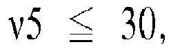

- The wide angle lens (100) according to claim 2, wherein
an object-image distance "D" and the focal length "f0" satisfy the following conditional expression:
- The wide angle lens (100) according to claim 1, wherein
the first lens (L1) is a glass lens. - The wide angle lens (100) according to claim 10, wherein
when a center thickness of the sixth lens (L6) is "T6" and a peripheral thickness of a light effective area on an object side face (13) of the sixth lens is "C6", the center thickness "T6" and the peripheral thickness "C6" satisfy the following conditional expression:
- The wide angle lens (100) according to claim 11, wherein
an Abbe number "v5" of the fifth lens (L5) and an Abbe number "v6" of the sixth lens (L6) satisfy the following conditional expression:

- The wide angle lens (100) according to claim 12, wherein
an object-image distance "D" and the focal length "f0" satisfy the following conditional expression:
Applications Claiming Priority (1)
| Application Number | Priority Date | Filing Date | Title |
|---|---|---|---|
| JP2016194138A JP2018055045A (en) | 2016-09-30 | 2016-09-30 | Wide angle lens |
Publications (1)
| Publication Number | Publication Date |
|---|---|
| EP3301492A1 true EP3301492A1 (en) | 2018-04-04 |
Family
ID=59974283
Family Applications (1)
| Application Number | Title | Priority Date | Filing Date |
|---|---|---|---|
| EP17193634.7A Withdrawn EP3301492A1 (en) | 2016-09-30 | 2017-09-28 | Wide angle lens |
Country Status (4)
| Country | Link |
|---|---|
| US (1) | US10162148B2 (en) |
| EP (1) | EP3301492A1 (en) |
| JP (1) | JP2018055045A (en) |
| CN (1) | CN107884914A (en) |
Cited By (3)
| Publication number | Priority date | Publication date | Assignee | Title |
|---|---|---|---|---|
| EP3460555A1 (en) * | 2017-09-21 | 2019-03-27 | Nidec Sankyo Corporation | Lens unit |
| CN109581636A (en) * | 2017-11-07 | 2019-04-05 | 玉晶光电(厦门)有限公司 | Optical imaging lens |
| CN110908096A (en) * | 2019-12-19 | 2020-03-24 | 广州晶和光电科技有限公司 | Vehicle-mounted lens |
Families Citing this family (14)
| Publication number | Priority date | Publication date | Assignee | Title |
|---|---|---|---|---|
| TWI610110B (en) | 2017-04-14 | 2018-01-01 | 大立光電股份有限公司 | Photographic system lens group, image capturing device and electronic device |
| TWI641865B (en) | 2017-09-27 | 2018-11-21 | 大立光電股份有限公司 | Optical imaging lens set, image capturing device and electronic device |
| TWI650592B (en) | 2018-04-18 | 2019-02-11 | 大立光電股份有限公司 | Camera optical lens group, image capturing device and electronic device |
| CN110488471B (en) * | 2018-05-14 | 2021-10-22 | 宁波舜宇车载光学技术有限公司 | Optical lens |
| CN108445609B (en) * | 2018-06-05 | 2019-10-22 | 浙江舜宇光学有限公司 | Camera lens group |
| TWI670516B (en) * | 2018-06-13 | 2019-09-01 | 大立光電股份有限公司 | Photographing optical lens system, image capturing unit and electronic device |
| CN109061842B (en) * | 2018-09-21 | 2024-03-29 | 协益电子(苏州)有限公司 | Optical lens and automobile data recorder |
| JP7269800B2 (en) * | 2019-06-24 | 2023-05-09 | ニデックインスツルメンツ株式会社 | wide angle lens |
| JP2021012311A (en) | 2019-07-08 | 2021-02-04 | 株式会社リコー | Imaging optical system, imaging apparatus, stereo camera, distance measuring device, and movable body |
| CN119676548A (en) | 2019-07-11 | 2025-03-21 | 华为技术有限公司 | Lens, camera and electronic device |
| CN112114417B (en) * | 2020-09-24 | 2023-04-14 | 玉晶光电(厦门)有限公司 | Optical lens group |
| CN115508982A (en) * | 2022-09-20 | 2022-12-23 | 东莞市宇瞳玖洲光学有限公司 | Car big wide angle glass of rule level, plastic lens hybrid lens |
| CN115755340A (en) * | 2022-11-16 | 2023-03-07 | 中山联合光电研究院有限公司 | Video lens and electronic equipment |
| CN119376071B (en) * | 2024-12-27 | 2025-05-13 | 宁波舜宇车载光学技术有限公司 | Optical lenses and electronic equipment |
Citations (4)
| Publication number | Priority date | Publication date | Assignee | Title |
|---|---|---|---|---|
| JPS4947700B1 (en) | 1970-06-06 | 1974-12-17 | ||
| WO2009084842A2 (en) * | 2007-12-27 | 2009-07-09 | Nanophotonics Co., Ltd. | Fisheye lens |
| US20160077313A1 (en) * | 2014-09-12 | 2016-03-17 | Nidec Sankyo Corporation | Wide angle lens |
| CN105807404A (en) * | 2014-12-31 | 2016-07-27 | 信泰光学(深圳)有限公司 | Wide-angle lens |
Family Cites Families (3)
| Publication number | Priority date | Publication date | Assignee | Title |
|---|---|---|---|---|
| JP2007279632A (en) * | 2006-04-12 | 2007-10-25 | Matsushita Electric Ind Co Ltd | Super wide angle lens |
| JP4947700B2 (en) * | 2006-09-21 | 2012-06-06 | 富士フイルム株式会社 | Wide-angle imaging lens, imaging device, and camera module |
| JP2013073156A (en) * | 2011-09-29 | 2013-04-22 | Fujifilm Corp | Image pickup lens and image pickup apparatus |
-
2016
- 2016-09-30 JP JP2016194138A patent/JP2018055045A/en active Pending
-
2017
- 2017-09-28 EP EP17193634.7A patent/EP3301492A1/en not_active Withdrawn
- 2017-09-28 US US15/717,948 patent/US10162148B2/en active Active
- 2017-09-28 CN CN201710905602.5A patent/CN107884914A/en not_active Withdrawn
Patent Citations (4)
| Publication number | Priority date | Publication date | Assignee | Title |
|---|---|---|---|---|
| JPS4947700B1 (en) | 1970-06-06 | 1974-12-17 | ||
| WO2009084842A2 (en) * | 2007-12-27 | 2009-07-09 | Nanophotonics Co., Ltd. | Fisheye lens |
| US20160077313A1 (en) * | 2014-09-12 | 2016-03-17 | Nidec Sankyo Corporation | Wide angle lens |
| CN105807404A (en) * | 2014-12-31 | 2016-07-27 | 信泰光学(深圳)有限公司 | Wide-angle lens |
Cited By (4)
| Publication number | Priority date | Publication date | Assignee | Title |
|---|---|---|---|---|
| EP3460555A1 (en) * | 2017-09-21 | 2019-03-27 | Nidec Sankyo Corporation | Lens unit |
| CN109581636A (en) * | 2017-11-07 | 2019-04-05 | 玉晶光电(厦门)有限公司 | Optical imaging lens |
| CN109581636B (en) * | 2017-11-07 | 2024-04-26 | 玉晶光电(厦门)有限公司 | Optical imaging lens |
| CN110908096A (en) * | 2019-12-19 | 2020-03-24 | 广州晶和光电科技有限公司 | Vehicle-mounted lens |
Also Published As
| Publication number | Publication date |
|---|---|
| US10162148B2 (en) | 2018-12-25 |
| CN107884914A (en) | 2018-04-06 |
| US20180095237A1 (en) | 2018-04-05 |
| JP2018055045A (en) | 2018-04-05 |
Similar Documents
| Publication | Publication Date | Title |
|---|---|---|
| EP3301495B1 (en) | Wide angle lens | |
| US10162148B2 (en) | Wide angle lens | |
| EP1712944B1 (en) | Imaging lens | |
| US7193793B2 (en) | Imaging lens | |
| US9690080B2 (en) | Wide angle lens | |
| US20200174227A1 (en) | Imaging lens | |
| EP1742094B1 (en) | Imaging lens | |
| US20200249435A1 (en) | Imaging lens | |
| US9329364B2 (en) | Optical lens system | |
| US9323027B2 (en) | Optical lens system | |
| US20190086640A1 (en) | Imaging lens | |
| US11644649B2 (en) | Optical imaging lens assembly | |
| EP3964875A1 (en) | Optical lens group, camera and terminal device | |
| EP1830211A1 (en) | Optical device | |
| US20130120859A1 (en) | Optical lens system for image taking | |
| US10976524B2 (en) | Five-piece optical lens system with a wide field of view | |
| US11131835B2 (en) | Imaging lens | |
| US9304302B2 (en) | Wide-angle lens | |
| US20190086636A1 (en) | Imaging lens composed of five optical elements | |
| KR20220137604A (en) | Optical imaging system | |
| US20190235207A1 (en) | Imaging lens | |
| EP3379316A1 (en) | Imaging lens | |
| US20200225448A1 (en) | Imaging lens | |
| US9612422B2 (en) | Photographing lens system | |
| KR20200083121A (en) | Optical imaging system |
Legal Events
| Date | Code | Title | Description |
|---|---|---|---|
| PUAI | Public reference made under article 153(3) epc to a published international application that has entered the european phase |
Free format text: ORIGINAL CODE: 0009012 |
|
| STAA | Information on the status of an ep patent application or granted ep patent |
Free format text: STATUS: REQUEST FOR EXAMINATION WAS MADE |
|
| 17P | Request for examination filed |
Effective date: 20170928 |
|
| AK | Designated contracting states |
Kind code of ref document: A1 Designated state(s): AL AT BE BG CH CY CZ DE DK EE ES FI FR GB GR HR HU IE IS IT LI LT LU LV MC MK MT NL NO PL PT RO RS SE SI SK SM TR |
|
| AX | Request for extension of the european patent |
Extension state: BA ME |
|
| STAA | Information on the status of an ep patent application or granted ep patent |
Free format text: STATUS: THE APPLICATION IS DEEMED TO BE WITHDRAWN |
|
| 18D | Application deemed to be withdrawn |
Effective date: 20181005 |