EP3301451A1 - Qc material, system and method - Google Patents
Qc material, system and method Download PDFInfo
- Publication number
- EP3301451A1 EP3301451A1 EP16191700.0A EP16191700A EP3301451A1 EP 3301451 A1 EP3301451 A1 EP 3301451A1 EP 16191700 A EP16191700 A EP 16191700A EP 3301451 A1 EP3301451 A1 EP 3301451A1
- Authority
- EP
- European Patent Office
- Prior art keywords
- detector
- substance
- procedure
- carrier particles
- vitro diagnostic
- Prior art date
- Legal status (The legal status is an assumption and is not a legal conclusion. Google has not performed a legal analysis and makes no representation as to the accuracy of the status listed.)
- Granted
Links
Images




Classifications
-
- G—PHYSICS
- G01—MEASURING; TESTING
- G01N—INVESTIGATING OR ANALYSING MATERIALS BY DETERMINING THEIR CHEMICAL OR PHYSICAL PROPERTIES
- G01N33/00—Investigating or analysing materials by specific methods not covered by groups G01N1/00 - G01N31/00
- G01N33/48—Biological material, e.g. blood, urine; Haemocytometers
- G01N33/50—Chemical analysis of biological material, e.g. blood, urine; Testing involving biospecific ligand binding methods; Immunological testing
- G01N33/72—Chemical analysis of biological material, e.g. blood, urine; Testing involving biospecific ligand binding methods; Immunological testing involving blood pigments, e.g. haemoglobin, bilirubin or other porphyrins; involving occult blood
-
- G—PHYSICS
- G01—MEASURING; TESTING
- G01N—INVESTIGATING OR ANALYSING MATERIALS BY DETERMINING THEIR CHEMICAL OR PHYSICAL PROPERTIES
- G01N21/00—Investigating or analysing materials by the use of optical means, i.e. using sub-millimetre waves, infrared, visible or ultraviolet light
- G01N21/17—Systems in which incident light is modified in accordance with the properties of the material investigated
- G01N21/47—Scattering, i.e. diffuse reflection
- G01N21/4785—Standardising light scatter apparatus; Standards therefor
-
- G—PHYSICS
- G01—MEASURING; TESTING
- G01N—INVESTIGATING OR ANALYSING MATERIALS BY DETERMINING THEIR CHEMICAL OR PHYSICAL PROPERTIES
- G01N33/00—Investigating or analysing materials by specific methods not covered by groups G01N1/00 - G01N31/00
- G01N33/48—Biological material, e.g. blood, urine; Haemocytometers
- G01N33/50—Chemical analysis of biological material, e.g. blood, urine; Testing involving biospecific ligand binding methods; Immunological testing
- G01N33/53—Immunoassay; Biospecific binding assay; Materials therefor
- G01N33/543—Immunoassay; Biospecific binding assay; Materials therefor with an insoluble carrier for immobilising immunochemicals
- G01N33/54393—Improving reaction conditions or stability, e.g. by coating or irradiation of surface, by reduction of non-specific binding, by promotion of specific binding
-
- G—PHYSICS
- G01—MEASURING; TESTING
- G01N—INVESTIGATING OR ANALYSING MATERIALS BY DETERMINING THEIR CHEMICAL OR PHYSICAL PROPERTIES
- G01N33/00—Investigating or analysing materials by specific methods not covered by groups G01N1/00 - G01N31/00
- G01N33/48—Biological material, e.g. blood, urine; Haemocytometers
- G01N33/50—Chemical analysis of biological material, e.g. blood, urine; Testing involving biospecific ligand binding methods; Immunological testing
- G01N33/72—Chemical analysis of biological material, e.g. blood, urine; Testing involving biospecific ligand binding methods; Immunological testing involving blood pigments, e.g. haemoglobin, bilirubin or other porphyrins; involving occult blood
- G01N33/728—Bilirubin; including biliverdin
-
- G—PHYSICS
- G01—MEASURING; TESTING
- G01N—INVESTIGATING OR ANALYSING MATERIALS BY DETERMINING THEIR CHEMICAL OR PHYSICAL PROPERTIES
- G01N33/00—Investigating or analysing materials by specific methods not covered by groups G01N1/00 - G01N31/00
- G01N33/48—Biological material, e.g. blood, urine; Haemocytometers
- G01N33/50—Chemical analysis of biological material, e.g. blood, urine; Testing involving biospecific ligand binding methods; Immunological testing
- G01N33/96—Chemical analysis of biological material, e.g. blood, urine; Testing involving biospecific ligand binding methods; Immunological testing involving blood or serum control standard
-
- G—PHYSICS
- G01—MEASURING; TESTING
- G01N—INVESTIGATING OR ANALYSING MATERIALS BY DETERMINING THEIR CHEMICAL OR PHYSICAL PROPERTIES
- G01N2496/00—Reference solutions for assays of biological material
- G01N2496/15—Reference solutions for assays of biological material containing dyes to mimic optical absorption of, e.g. hemoglobin
-
- G—PHYSICS
- G01—MEASURING; TESTING
- G01N—INVESTIGATING OR ANALYSING MATERIALS BY DETERMINING THEIR CHEMICAL OR PHYSICAL PROPERTIES
- G01N33/00—Investigating or analysing materials by specific methods not covered by groups G01N1/00 - G01N31/00
- G01N33/48—Biological material, e.g. blood, urine; Haemocytometers
- G01N33/50—Chemical analysis of biological material, e.g. blood, urine; Testing involving biospecific ligand binding methods; Immunological testing
- G01N33/72—Chemical analysis of biological material, e.g. blood, urine; Testing involving biospecific ligand binding methods; Immunological testing involving blood pigments, e.g. haemoglobin, bilirubin or other porphyrins; involving occult blood
- G01N33/721—Haemoglobin
Definitions
- the present invention refers to a QC material for in-vitro-diagnostics, to a system comprising the QC material, to a method of performing a QC procedure using the QC material and to a method of manufacturing the QC material.
- one or more reference samples also called QC samples
- QC samples with known values of the parameters of interest are typically also measured, in the same way as patient samples are measured, in order to further check that the calibrated instrument is actually within the specifications or admissible range.
- QC samples are supplied in three levels that correspond to different concentration ranges of the parameters.
- a QC material is here introduced that solves this interference problem in general. This is achieved by isolation of the interfering substance or substances from other substances in the same solution, as claimed.
- a method of manufacturing the QC material is also introduced.
- An in-vitro diagnostic system comprising the QC material and a method of using the QC material are also introduced, which is particularly advantageous when using different detectors for different parameters.
- a further advantage is the increased choice of substances that can be used as standard substances in QC materials and the possibility to increase the number of different substances in the same QC material.
- a further advantage is that the same QC material may be used for performing a QC procedure on different in-vitro systems by having respective QC substances in the same QC material.
- a Quality Control (QC) material for performing a QC procedure with respect to at least one detector comprises at least one QC substance that interferes with another QC substance or with the performance and/or lifetime of the at least one detector. More in particular, the QC material comprises at least one first QC substance and at least one second QC substance, where the at least one first QC substance is interferable with the at least one second QC substance or with the performance and/or lifetime of the at least one detector.
- the at least one first QC substance In order to prevent that the at least one first QC substance interferes with the at least one second QC substance or with the performance and/or lifetime of the at least one detector the at least one first QC substance is entrapped by carrier particles that isolate the at least one first QC substance in the QC material.
- quality control material or for short “QC material” is herein used to intend either a calibration material, typically a calibration solution, or a quality control sample (QC sample) or both, unless explicitly stated.
- QC procedure is herein used to intend either a calibration procedure or a check with a quality control sample or both, unless explicitly stated.
- the QC material comprises a plurality of QC substances for performing the QC procedure with respect to different parameters respectively.
- a “parameter” can be a measurable property of the test sample with diagnostic meaning, such as turbidity, color, viscosity, hematocrit, coagulation time, and the like or it can be an analyte present in the test sample, the presence and/or concentration of which has also a diagnostic value.
- test sample refers to a biological material suspected of containing one or more analytes of interest and whose detection, qualitative and/or quantitative, may be associated to a clinical condition.
- the test sample can be derived from any biological source, such as a physiological fluid, including blood, saliva, ocular lens fluid, cerebral spinal fluid, sweat, urine, milk, ascites fluid, mucous, synovial fluid, peritoneal fluid, amniotic fluid, tissue, cells or the like.
- the test sample can be pretreated prior to use, such as preparing plasma from blood, diluting viscous fluids, lysis or the like; methods of treatment can involve filtration, centrifugation, distillation, concentration, inactivation of interfering components, and the addition of reagents.
- a test sample may be used directly as obtained from the source in some cases or following a pretreatment and/or sample preparation workflow to modify the character of the sample, e.g.
- analyte(s) of interest after adding an internal standard, after being diluted with another solution or after having being mixed with reagents e.g. to enable carrying out one or more in vitro diagnostic tests, or for enriching (extracting/separating/concentrating) analytes of interest and/or for removing matrix components potentially interfering with the detection of the analyte(s) of interest.
- the test sample is blood or a blood derivative such as plasma or serum.
- analytes of interest are gases, such as O 2 and CO 2 , blood electrolytes such as Sodium (Na + ), Potassium (K + ), Chloride (Cl - ), Calcium (Ca ++ ), protons (H + ) in relation to pH, metabolites such as Glucose and Lactate, drugs of abuse, therapeutic drugs, hormones, markers, proteins and the like.
- Other analytes of interest are hemoglobin, hemoglobin derivatives such as Deoxygenated hemoglobin, Oxyhemoglobin, Carboxyhemoglobin, Methemoglobin, and bilirubin.
- a parameter of interest is hematocrit. The list is however not exhaustive.
- a "QC substance" can be an analyte identical to an analyte of interest, the concentration of which is known, or that generates by reaction an analyte identical to an analyte of interest, the concentration of which is known, e.g. CO 2 from bicarbonate, or it can be any other equivalent substance of known concentration, which mimics the analyte of interest or that can be otherwise correlated to a certain parameter of interest, e.g. a dye that behaves optically similar to hemoglobin or bilirubin.
- Different levels of the QC material with respective different concentrations of QC substances may be prepared for performing a QC procedure.
- a “carrier particle” is a chemical vector comprising a three-dimensional body structure that can hold and transport a QC substance by entrapment, e.g. by incorporation into its body or enclosure in its interior.
- the carrier particle prevents the QC substance from interacting/interfereing with other substances of the QC material and/or with the at least one detector while possibly still retaining its properties as a QC substance for performing a QC procedure.
- the carrier particle is a microscopic particle in the micrometer or sub-micrometer range, e.g. a nanoparticle.
- Carrier particles can be formed under certain conditions by mixing suitable reagents in the presence of the QC substance that is to be entrapped.
- the carrier particles are silica or polymeric particles. According to an embodiment, the carrier particles comprise a silica shell and the at least one first QC substance is enclosed in the silica shell.
- the first QC substance is enclosed in the silica shell by mixing the first QC substance with a surfactant and with a silicate or silane derivative, such as for example tetraethyl orthosilicate or (3-Aminopropyl)triethoxysilane or equivalent compound.
- a silicate or silane derivative such as for example tetraethyl orthosilicate or (3-Aminopropyl)triethoxysilane or equivalent compound.
- the surfactant is Cetyltrimethylammonium bromide (CTAB) or Triton X-100.
- CTAB Cetyltrimethylammonium bromide
- Triton X-100 Triton X-100.
- CTAB Cetyltrimethylammonium bromide
- other surfactants may be used.
- the first QC substance is a dye that optically simulates one or more analytes of interest or whose optical properties may be correlated to the optical properties of one or more analytes of interest.
- the first QC substance is a dye that optically simulates hemoglobin or any derivative of hemoglobin, e.g. sulforhodamine B or rhodamine B.
- the first QC substance is a dye that optically simulates bilirubin, e.g. tartrazine.
- the first QC substance is a mixture of a dye that optically simulates hemoglobin or any derivative of hemoglobin such as sulforhodamine B and a dye that optically simulates bilirubin such as tartrazine. Any other dyes with similar or correlateable optical properties may however be used.
- a method of manufacturing a QC material comprises mixing the at least one first QC substance with a surfactant and with a silicate or silane derivative, e.g. with tetraethyl orthosilicate or (3-Aminopropyl)triethoxysilane or equivalent compound, for obtaining silica carrier particles that entrap the at least one first QC substance.
- a silicate or silane derivative e.g. with tetraethyl orthosilicate or (3-Aminopropyl)triethoxysilane or equivalent compound
- the method further comprises isolating the silica carrier particles and adding the carrier particles to a solution comprising the at least one second QC substance in order to form the QC material for performing a QC procedure with respect to the at least one detector.
- Isolating the silica carrier particles may be achieved for example by centrifugation followed by washing the excess of first QC substance remained in the supernatant. This procedure may be repeated as necessary comprising resuspending the carrier particles. However, other isolating procedures may be used as well, like filtration, evaporation, and the like.
- Polymeric carrier particles may be for example obtained as alternative to silica carrier particles.
- An exemplary list of polymers that may be used includes Poly (N-isopropylacrylamide) (PNIPAM), Polypyrrole (PPy), Polyallylamine (PAH), Polymethylmethacrylate (PMMA), Polyethyleneimine (PEI), but is not limited thereto.
- PNIPAM Poly (N-isopropylacrylamide)
- PPy Polypyrrole
- PAH Polyallylamine
- PMMA Polymethylmethacrylate
- PEI Polyethyleneimine
- One possible procedure is based on a layer by layer assembly using electrostatic interactions, as e.g. disclosed in Langmuir 2004, 20, 6988-6992 .
- An in-vitro diagnostic system which comprises at least two detectors, in particular at least a first detector and a second detector for detecting at least two respective parameters of a test sample.
- the in-vitro diagnostic system further comprises the above QC material for performing a QC procedure with respect to the first detector and the second detector, where the at least one first QC substance is required for performing the QC procedure with respect to the first detector but is interferable with the performance and/or lifetime of the second detector, and the at least one second QC substance is required for performing the QC procedure with respect to the second detector.
- the at least one first QC substance is entrapped by the carrier particles it is thereby prevented from interfering with the performance and/or lifetime of the second detector.
- an "in-vitro diagnostic system” is a laboratory automated system dedicated to the analysis of samples for in vitro diagnostics and making use of QC materials.
- the in-vitro diagnostic system may have different configurations according to the need and/or according to the desired laboratory workflow.
- the in-vitro diagnostic system can comprise one or more analytical apparatuses, comprising at least one detector, designed to execute respective workflows that are optimized for one or more certain types of analysis, and to detect certain types of parameters, e.g. gases, electrolytes, metabolites, clinical chemistry analytes, immunochemistry analytes, coagulation parameters, hematology parameters, etc.
- the in-vitro diagnostic system may comprise one analytical apparatus or a combination of any of such analytical apparatuses with respective workflows and respective detectors, where pre-analytical and/or post analytical modules may be coupled to individual analytical apparatuses or be shared by a plurality of analytical apparatuses. In alternative pre-analytical and/or post-analytical functions may be performed by units integrated in an analytical apparatus.
- the in-vitro diagnostic system can comprise functional units such as liquid handling units for pipetting and/or pumping and/or mixing of samples and/or reagents and/or system fluids, and also functional units for sorting, storing, transporting, identifying, separating, detecting.
- the in-vitro diagnostic system comprises an analytical apparatus with at least a first detector and a second detector and which uses one or more QC materials.
- the in-vitro diagnostic system comprises at least two analytical apparatuses with at least a first detector and a second detector respectively and which uses one or more QC materials.
- the first detector comprises an optical unit for optically detecting at least one analyte of interest.
- the first detector is however not limited to optical detectors.
- the optical unit is an oximetry unit for photometrically detecting any one or more of hemoglobin, including any derivatives of hemoglobin, and bilirubin.
- the oximetry unit comprises at least one light source, at least one optical sensor, e.g. a photodiode array, a sample cuvette arranged between the light source and the optical sensor and optical elements such as lenses, apertures, possibly mirror(s), possibly filter(s), possibly a grating monochromator, a polychromator or prism, for guiding light from the light source to a test sample in the cuvette and from the test sample to the at least one optical sensor.
- Absorbance and in particular an absorbance spectrum and/or scattering can be measured. Absorbance can be measured also directly in a flow path.
- the at least one second detector comprises a flow-through sensoric path for detecting any one or more of a gas, an electrolyte, a metabolite.
- the flow-through sensoric path may comprise a sensor for each parameter, and may be embodied in a replaceable cartridge-like structure comprising a plurality of sensors.
- the in-vitro diagnostic system may comprise a plurality of second detectors, each having a sensoric path comprising a sensor dedicated to one parameter, and which may also be replaceable or not.
- the sensor is a thick-film sensor. A test sample may thus flow into the one or more sensoric paths and different parameters may be determined by respective sensors.
- the at least one second detector comprises any one or more of a PO2 sensor, a PCO2 sensor, a pH sensor, one or more ion selective electrode (ISE) sensors for determining electrolyte values such Na+, K+, Ca2+ and Cl - , one or more metabolite sensors for determining parameters such as lactate and glucose.
- a PO2 sensor a PCO2 sensor
- a pH sensor a pH sensor
- ISE ion selective electrode
- a PO2 sensor typically functions according to the Clark measurement principle. This means that oxygen diffuses through a membrane to a gold multi-wire system with negative electric potential inside of the sensor. The oxygen is reduced here, which generates an electric current that is proportional to the oxygen contained in the sample. This current is measured amperometrically.
- a PCO2 sensor typically is a Severinghouse-type sensor. This means that CO2 diffuses through a membrane similar to the oxygen sensor. In the sensor, the CO2 concentration changes and causes a change of the pH value, which is measured potentiometrically.
- a pH sensor typically comprises a pH-sensitive membrane. Depending on the pH value of the test sample, electric potential is generated at the boundary layer between the membrane and the sample. This potential can be measured potentiometrically by a reference sensor.
- Na+, K+, Ca2+ and Cl - ISE sensors typically work according to the potentiometric measuring principle. They differ only by different membrane materials that enable sensitivity for the respective electrolytes.
- the glucose sensor typically makes use of glucose oxidase enzyme, by which glucose is oxidized into gluconolactone with oxygen from the air.
- the H2O2 that is formed in this process is determined amperometrically by a manganese dioxide/carbon electrode. Since the sensor restores the oxygen that is needed for oxidation of glucose in the enzymatic reaction, the glucose value is measured independently of the oxygen concentration in the test sample.
- the Lactate sensor typically makes use of lactate oxidase enzyme, by which lactate is oxidized into pyruvate with oxygen from the air.
- the H2O2 that is formed in this process is determined amperometrically in a manner similar to the glucose sensor.
- the at least one second detector comprises additional or different sensors, eventually based on a different principle, e.g. the conductometric principle.
- the second detector comprises at least one sensor, the performance and/or lifetime of which is affected by the at least one first QC substance.
- the affected sensor is a sensor comprising a membrane that can interact, e.g. by sorption, including adsorbion and/or absorbtion, with the at least one first QC substance, for example an ion selective electrode sensor.
- the first QC substance interferes with the intended function of the membrane. In particular, it competes with the parameter, e.g. with the electrolyte that the sensor is intended to measure, affecting the membrane permeability and selectivity to that electrolyte.
- the first QC substance is a negatively charged substance, like for example sulphorodamine B or tartrazin, it can interfere with the chloride ISE sensor comprising a Cl - selective membrane.
- the first QC substance is a positively charged substance it can interfere with any other of the other sensors selective to positively charged parameters.
- the performance of the sensor can become worse with time and eventually shorten its lifetime. Moreover, if the sensor is integrated into a sensor cartridge with other sensors, then the entire cartridge needs to be replaced. This results in increased costs and increased downtime of the in-vitro diagnostic system.
- One possible side effect associated with the use of carrier particles can be an enhanced scattering effect. If the detector subject to the QC procedure is based on a non-optical principle, e.g. on the amperometric, potentiometric or conductometric measurement principle, and the QC substance required for performing the QC procedure by the detector is not the one entrapped by the carrier particles, scattering does not play any role. This is the case for the second detector according to certain embodiments. Scattering may be generated and may interfere with the QC procedure if the detector subject to the QC procedure is an optical detector and if the QC procedure is based on optical detection of a QC substance. This may be the case for the first detector, according to certain embodiments. Depending on the particular optical setup, light scattering may be taken into account when measuring absorbance and is not necessarily a negative side effect. In other circumstances however, it is desirable to minimize any scattering effects.
- a non-optical principle e.g. on the amperometric, potentiometric or conductometric measurement
- the in-vitro diagnostic system comprises a disruptive device associated with the first detector for disrupting the carrier particles and releasing the at least one first QC substance.
- any scattering effect depending on the chemical structure of the at least one first QC substance, it may be desirable to disrupt the carrier particles at the first detector where the released first QC substance(s) cannot interfere with the performance and/or lifetime of the second detector. By this, it can be ensured that the at least one first QC substance behaves as in any other QC material comprising that same QC substance without being entrapped by carrier particles. Thereby any possible alteration of the QC procedure is also avoided, e.g. a possible shift in the absorbance spectrum or of the intensity.
- the disruptive device is an ultrasound generator, e.g. comprising a piezo element, for generating and transferring ultrasound waves to the QC material in the optical cuvette or before entering the optical cuvette.
- ultrasound generator e.g. comprising a piezo element
- Other types of disruptive devices may however be used such as for example based on mechanical stressing, temperature or ablative decomposition.
- the disruptive device is also a hemolizer used to disrupt cells, in particular red blood cells in a blood sample and to release hemoglobin from the cells, as the cells may also generate scattering.
- An in-vitro diagnostic method comprises performing a QC procedure with respect to a first detector and/or to a second detector.
- the method further comprises providing a QC material according to any of the mentioned embodiments to the first detector and/or to the second detector, where the at least one first QC substance entrapped by the carrier particles is required for performing the QC procedure with respect to the first detector and the at least one second QC substance is required for performing the QC procedure with respect to the second detector.
- first detector and the second detector do not have to be arranged necessarily in the same in-vitro diagnostic system.
- This method refers to the use of the same QC material for performing a QC procedure with respect to different detectors regardless of their arrangement in space and regardless of the time of use.
- performing the QC procedure with respect to the first detector comprises disrupting the carrier particles for releasing the at least one first QC substance, where the released at least one first QC substance at the first detector cannot interfere with the performance and/or lifetime of the second detector.
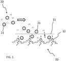
- FIG. 1 schematically shows a membrane 11 used in an ion selective electrode (ISE) sensor 10, in this case a chloride (Cl - ) selective membrane 11.
- ISE ion selective electrode
- Cl - chloride
- This chloride selective membrane 11 comprises a quaternary ammonium salt 12, tridodecylmethylammoniumchloride (TDMAC), which acts as a positively charged ion-exchanger.
- the membrane 11 can be formed by embedding the quaternary ammonium salt 12 for example in polyvinylchloride (PVC) or in an epoxy resin, e.g. Araldit composed of mainly diglycidyl end capped bisphenol A (DGEBPA) and polypropylene glycol-diglycidyl ether (PPG-DGE), which is hardened and crosslinked with an aliphatic tetraamine.
- PVC polyvinylchloride
- Araldit composed of mainly diglycidyl end capped bisphenol A (DGEBPA) and polypropylene glycol-diglycidyl ether (PPG-DGE), which is hardened and crosslinked with an aliphatic tetraamine.
- DGEBPA diglycidyl end
- selectivity decreases with the increased hydrophilicity of the ion and increases with increased hydrophobicity of the ion.
- salicylate which is more hydrophobic than Cl - , can produce a positive interference.
- a prior art QC material 20 comprising a at least one first QC substance 21, for performing a QC procedure with respect to another detector (not shown in FIG.
- the first QC substance 21 may compete with the second QC substance Cl - in the ion exchange process with the membrane 11, especially if the first QC substance 21 is more hydrophobic than Cl - , e.g. if the first QC substance 21 is a dye such as sulphorodamine B or tartrazin or both. Eventually more and more of the first QC substance 21 is adsorbed/absorbed by the membrane 11 and it cannot be replaced by chloride. This is an example of how a QC substance can interfere with the performance and/or lifetime of a detector.
- FIG. 2 schematically shows a new QC material 30 and a method of manufacturing it.
- the method comprises mixing at least one first QC substance 21 that is interferable with a second QC substance or with the performance and/or lifetime of at least one detector, with a surfactant 31 (represented as a micelle in FIG. 2 ) and with a silicate or silane derivative, tetraethyl orthosilicate (TEOS) in this case, for obtaining carrier particles, in this case silica capsules 32 that entrap by enclosure the at least one first QC substance 21 in a silica shell.
- a surfactant 31 represented as a micelle in FIG. 2
- TEOS tetraethyl orthosilicate
- silica carrier particles entrapping different types of substances including dyes such as Rhodamine B, are known in the art, as e.g. disclosed by Gomes et al. (2014), Optical Materials, 36, 1197-1202 .
- the carrier particles obtained have generally different applications.
- silica capsules enclosing for example sulforhodamine B can be obtained.
- Cetyltrimethylammonium bromide (CTAB) is added as surfactant to a solution of NH 4 OH. The mixture is stirred until the surfactant is dissolved. Afterwards, Sulforhodamine B is added to the solution and stirred until also dissolved. Thereafter a solution of TEOS in ethanol is added and left reacting at room temperature under stirring thereby obtaining the silica capsules.
- the silica capsules can be recovered (isolated) by centrifugation and excess of dye can be removed by repeated cycles of washing/resuspending/centrifuging. More specific conditions can be found for example in the referenced article.
- the method of manufacturing the new QC material 30 further comprises isolating the silica capsules 32 and adding the silica capsules 32, in the desired amount, to a solution comprising at least one second QC substance 22, 23, 24, in order to form the QC material 30 comprising the at least one QC substance 21 enclosed in the silica capsules 32 in the desired concentration, for performing a QC procedure with respect to the at least one detector requiring any of the first and second QC substances. So, when it comes to a detector where the first QC substance 21 would interfere with its performance and/or lifetime, it is prevented from interfering. Also, it is prevented from interfering with any other QC substance in the same QC material 30.
- FIG. 3 schematically shows how the interference problem illustrated in connection with FIG. 1 can be prevented by using the new QC material 30.
- the QC material 30 includes, for continued reference, also the QC substance Cl - along other second QC substances 22, 23, 24.
- the first QC substance 21 is enclosed in the silica capsules 32, it is prevented to adsorb/absorb into the membrane 11 and to compete in the ion exchange process with the second QC substance Cl - , which is the QC substance for performing a QC procedure with respect to the chloride sensor 10.
- the first QC substance 21 therefore cannot interfere with the performance and lifetime of the chloride sensor 10.
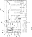
- FIG. 4 shows schematically an example of an in-vitro diagnostic system 100.
- the in-vitro diagnostic system 100 comprises a first detector 40 and a second detector 50 for detecting respective parameters of a test sample 1.
- the first detector 40 comprises an optical unit 41 and in particular an oximetry unit for photometrically detecting any one or more of hemoglobin, including derivatives of hemoglobin, and bilirubin.
- the oximetry unit 41 comprises a light source 42, an optical sensor 43 such as a photodiode array, a sample cuvette 44 arranged between the light source 42 and the optical sensor 43 and optical elements such as lenses and a polychromator (not shown), for guiding light from the light source 42 to a test sample 1 in the cuvette 44 and from the test sample 1 to the optical sensor 43 for measuring an absorbance spectrum.
- the second detector 50 is embodied as a plug-in cartridge comprising a flow-through sensoric path 51, comprising a gas sensoric zone 52 comprising a PO 2 sensor, a PCO 2 sensor and a pH sensor, a metabolite sensoric zone 53, comprising a glucose sensor and a lactate sensor, and an electrolyte sensoric zone 54, comprising ISE sensors for detecting respectively Na + , K + , Ca 2+ , and the chloride ISE sensor 10 seen in connection to FIG. 1 .
- the in-vitro diagnostic system 100 further comprises fluidic lines 60, a fluid injector 61, valves 62 and pumps 63 for moving fluids through the fluidic lines 60 and in particular in and out of the cuvette 44 of the first detector 40 and/or through the sensoric path 51 of the second detector 50, where respective test sample parameters can be determined.
- the in-vitro diagnostic system 100 further comprises a fluid package 70 comprising fluid reservoirs, including a reference solution (REF) for the second detector 50, a first calibration material (Cal 1), a second calibration material (Cal 2), a standby solution (STDBY), a wetting fluid (WET) and two waste containers (W).
- the wetting fluid (WET) is used every time a new cartridge 50 is plugged for conditioning the new cartridge 50.
- the Na + , K + , Ca 2+ , Cl - , pH and CO 2 parameters are calibrated using the standby (STDBY) and CAL 2 solutions, which contain a defined quantity of electrolytes and acidic or alkaline components of a pH buffer system. By ensuring airtight access to the calibration solutions, the CO 2 content can be kept steady and then used as a basis for calibration.
- the CAL 2 solution contains a very low concentration of oxygen and thus is used to calibrate the low calibration point in a two-point calibration.
- the high calibration point is calibrated using the standby solution.
- the oxygen concentration of the standby solution corresponds to that of the ambient air.
- Calibrating the oximetry unit 41 requires wavelength calibration of the polychromator and layer thickness calibration of the cuvette 44.
- the optical unit 41 comprises a second light source (not shown), which is a neon lamp.
- the neon lamp is a gas discharge light, which emits only certain defined wavelengths. The peaks in the neon emission spectrum are used to calibrate the wavelength scale.
- Layer thickness of the cuvette 44 is calibrated using the CAL 2 solution which contains a dye for this purpose.
- the standby solution (STDBY) is also used for rinsing the fluidic lines 60, the flow-through path 51 and the cuvette 44.
- the in-vitro diagnostic system 100 further comprises QC materials 30 for performing other QC procedures with respect to the first detector 40 and the second detector 50 and in particular quality control samples, supplied in three levels of respective concentration ranges for each parameter.
- the QC materials 30 comprise QC substances in different concentrations for different levels, which are required for performing the QC procedure with respect to both the first detector 40 and the second detector 50.
- the QC substances there are two QC substances, sulphorodamine B and tartrazin, which are required for performing the QC procedure with respect to both the first detector 40 that are interferable with the performance and lifetime of the second detector 50, and in particular with that of the chloride ISE sensor in the electrolyte sensoric zone 54.
- the two interfearable QC substances are enclosed in carrier particles as seen e.g. in connection to FIG. 2 and 3 , and are thereby prevented from interfering with the performance and/or lifetime of the second detector 50.
- the in-vitro diagnostic system 100 further comprises a disruptive device 45 associated with the first detector 40 for disrupting the carrier particles and releasing the enclosed QC substances.
- the disruptive device 45 is an ultrasound generator that transfers ultrasound waves to the QC material 30 in the fluidic lines 60 before entering the optical cuvette 44.
- the disruptive device 45 is also a hemolizer used to disrupt cells, in particular red blood cells in a blood sample and to release hemoglobin from the cells.
- the CAL 1 and STDBY solutions comprise mixtures of QC substances for performing calibration procedures and hence QC procedures, they do not contain in this specific example any QC substances that interfere with other QC substances or with the performance and lifetime of any of the first and first detectors 40, 50. Therefore, they do not contain any QC substance enclosed in carrier particles, although in other embodiments, the use of encapsulation of QC substances in carrier particles can be used for these or other solutions with similar purpose as well.
- the dye in the CAL 2 solution that is used for calibrating the cuvette 44 in the first detector 40 is also entrapped by carrier particles so that when CAL 2 is used for calibrating the second detector 50, the dye cannot interfere with the performance and/or lifetime of the detector 50.
- the calibration material CAL 2 is another example of QC material.
- FIG. 5 shows schematically an in-vitro diagnostic method comprising a QC procedure in connection to the in-vitro diagnostic system 100 of FIG. 4 and using a QC material 30 as discussed in connection to FIG. 2 and 4 .
- the method comprises performing a QC procedure with respect to the first detector 40 and to the second detector 50.
- the method further comprises providing a QC material 30 to the first detector 40 and to the second detector 50, the QC material 30 comprising first QC substances that are required for performing the QC procedure with respect to the first detector 40 and second QC substances required for performing the QC procedure with respect to the second detector 50, where the first QC substances are entrapped by carrier particles in order to prevent the first QC substances to interfere with the performance and/or lifetime of the second detector 50.
- the QC material 30 is being provided to both the first detector 40 and the second detector 50 at the same time, it can be provided to any of the first detector 40 or the second detector 50 independently from each other at any time, according e.g. to a programmed schedule or on request.
- the carrier particles 32 of the QC material 30 can generate some light scattering.
- the QC procedure further comprises disrupting the carrier particles 32 with the disruptive device 45 for disrupting the carrier particles 32 and releasing the first QC substances 21 at the first detector 40 only, where the released first QC substances 21 at the first detector 40 cannot interfere with the performance and/or lifetime of the second detector 50. In this way any light scattering effect can be prevented or minimized.
Landscapes
- Health & Medical Sciences (AREA)
- Life Sciences & Earth Sciences (AREA)
- Engineering & Computer Science (AREA)
- Hematology (AREA)
- Immunology (AREA)
- Chemical & Material Sciences (AREA)
- Urology & Nephrology (AREA)
- Biomedical Technology (AREA)
- Molecular Biology (AREA)
- Physics & Mathematics (AREA)
- General Physics & Mathematics (AREA)
- Pathology (AREA)
- General Health & Medical Sciences (AREA)
- Biochemistry (AREA)
- Analytical Chemistry (AREA)
- Biotechnology (AREA)
- Medicinal Chemistry (AREA)
- Food Science & Technology (AREA)
- Microbiology (AREA)
- Cell Biology (AREA)
- Chemical Kinetics & Catalysis (AREA)
- Investigating Or Analysing Materials By Optical Means (AREA)
- Investigating Or Analysing Biological Materials (AREA)
- Investigating Or Analysing Materials By The Use Of Chemical Reactions (AREA)
Abstract
Description
- The present invention refers to a QC material for in-vitro-diagnostics, to a system comprising the QC material, to a method of performing a QC procedure using the QC material and to a method of manufacturing the QC material.
- In medicine, doctor's diagnosis and patient treatment often relies on the measurement of patient sample parameters carried out by in-vitro diagnostic instruments. As the life of patients may depend on the precision and the reliability of such measurements it is important that the instruments perform correctly.
- Thus, it is a general requirement for in-vitro diagnostic systems to implement a set of Quality Control (QC) procedures to check that the instruments are working correctly.
- One of these procedures is calibration. In most cases calibration is performed using standard solutions, with known concentrations. In this way it is possible to correlate a measured signal to a quantitative result. Calibration should be performed more or less frequently depending on the system and other variable factors which may affect performance. Depending on the circumstances, a two-point or one-point calibration may be performed, eventually with variable frequency.
- In addition, between consecutive calibrations, one or more reference samples, also called QC samples, with known values of the parameters of interest are typically also measured, in the same way as patient samples are measured, in order to further check that the calibrated instrument is actually within the specifications or admissible range.
- Typically, QC samples are supplied in three levels that correspond to different concentration ranges of the parameters.
- In some cases, rather than having different calibration solutions and a different QC samples for each different parameter, different standard substances with known concentration can be combined into a single calibration solution or a single QC sample respectively. In this way, the number of calibration solutions and QC samples can be reduced, and also the number of QC procedures can be reduced, since the same QC procedure can be applied to a plurality of parameters at the same time.
- One possible problem of this approach is that some QC substances present in the same solution may interfere with each other or if different detectors or measurement principles are used for different parameters respectively, QC substances that are intended for one detector may interfere with the performance and/or lifetime of another detector.
- A QC material is here introduced that solves this interference problem in general. This is achieved by isolation of the interfering substance or substances from other substances in the same solution, as claimed. A method of manufacturing the QC material is also introduced. An in-vitro diagnostic system comprising the QC material and a method of using the QC material are also introduced, which is particularly advantageous when using different detectors for different parameters. A further advantage is the increased choice of substances that can be used as standard substances in QC materials and the possibility to increase the number of different substances in the same QC material. A further advantage is that the same QC material may be used for performing a QC procedure on different in-vitro systems by having respective QC substances in the same QC material. Also, although reference is made to a QC material, the same concept of isolating an interfering substance in a complex mixture of substances in order to prevent interferences can be extended to other materials as well, including for example reagents or other fluids used by the in-vitro diagnostic system.
- A Quality Control (QC) material for performing a QC procedure with respect to at least one detector is introduced. In particular, the QC material comprises at least one QC substance that interferes with another QC substance or with the performance and/or lifetime of the at least one detector. More in particular, the QC material comprises at least one first QC substance and at least one second QC substance, where the at least one first QC substance is interferable with the at least one second QC substance or with the performance and/or lifetime of the at least one detector. In order to prevent that the at least one first QC substance interferes with the at least one second QC substance or with the performance and/or lifetime of the at least one detector the at least one first QC substance is entrapped by carrier particles that isolate the at least one first QC substance in the QC material.
- The term "quality control material" or for short "QC material" is herein used to intend either a calibration material, typically a calibration solution, or a quality control sample (QC sample) or both, unless explicitly stated. Analogously, the term "QC procedure" is herein used to intend either a calibration procedure or a check with a quality control sample or both, unless explicitly stated. The QC material comprises a plurality of QC substances for performing the QC procedure with respect to different parameters respectively.
- A "parameter" can be a measurable property of the test sample with diagnostic meaning, such as turbidity, color, viscosity, hematocrit, coagulation time, and the like or it can be an analyte present in the test sample, the presence and/or concentration of which has also a diagnostic value.
- The term "test sample" refers to a biological material suspected of containing one or more analytes of interest and whose detection, qualitative and/or quantitative, may be associated to a clinical condition.
- The test sample can be derived from any biological source, such as a physiological fluid, including blood, saliva, ocular lens fluid, cerebral spinal fluid, sweat, urine, milk, ascites fluid, mucous, synovial fluid, peritoneal fluid, amniotic fluid, tissue, cells or the like. The test sample can be pretreated prior to use, such as preparing plasma from blood, diluting viscous fluids, lysis or the like; methods of treatment can involve filtration, centrifugation, distillation, concentration, inactivation of interfering components, and the addition of reagents. A test sample may be used directly as obtained from the source in some cases or following a pretreatment and/or sample preparation workflow to modify the character of the sample, e.g. after adding an internal standard, after being diluted with another solution or after having being mixed with reagents e.g. to enable carrying out one or more in vitro diagnostic tests, or for enriching (extracting/separating/concentrating) analytes of interest and/or for removing matrix components potentially interfering with the detection of the analyte(s) of interest.
- According to an embodiment, the test sample is blood or a blood derivative such as plasma or serum. According to certain embodiments, analytes of interest are gases, such as O2 and CO2, blood electrolytes such as Sodium (Na+), Potassium (K+), Chloride (Cl-), Calcium (Ca++), protons (H+) in relation to pH, metabolites such as Glucose and Lactate, drugs of abuse, therapeutic drugs, hormones, markers, proteins and the like. Other analytes of interest are hemoglobin, hemoglobin derivatives such as Deoxygenated hemoglobin, Oxyhemoglobin, Carboxyhemoglobin, Methemoglobin, and bilirubin. According to an embodiment a parameter of interest is hematocrit. The list is however not exhaustive.
- A "QC substance" can be an analyte identical to an analyte of interest, the concentration of which is known, or that generates by reaction an analyte identical to an analyte of interest, the concentration of which is known, e.g. CO2 from bicarbonate, or it can be any other equivalent substance of known concentration, which mimics the analyte of interest or that can be otherwise correlated to a certain parameter of interest, e.g. a dye that behaves optically similar to hemoglobin or bilirubin.
- Different levels of the QC material with respective different concentrations of QC substances may be prepared for performing a QC procedure.
- A "carrier particle" is a chemical vector comprising a three-dimensional body structure that can hold and transport a QC substance by entrapment, e.g. by incorporation into its body or enclosure in its interior. In particular, the carrier particle prevents the QC substance from interacting/interfereing with other substances of the QC material and/or with the at least one detector while possibly still retaining its properties as a QC substance for performing a QC procedure. According to certain embodiments, the carrier particle is a microscopic particle in the micrometer or sub-micrometer range, e.g. a nanoparticle. Carrier particles can be formed under certain conditions by mixing suitable reagents in the presence of the QC substance that is to be entrapped.
- According to an embodiment, the carrier particles are silica or polymeric particles. According to an embodiment, the carrier particles comprise a silica shell and the at least one first QC substance is enclosed in the silica shell.
- According to an embodiment, the first QC substance is enclosed in the silica shell by mixing the first QC substance with a surfactant and with a silicate or silane derivative, such as for example tetraethyl orthosilicate or (3-Aminopropyl)triethoxysilane or equivalent compound.
- According to an embodiment, the surfactant is Cetyltrimethylammonium bromide (CTAB) or Triton X-100. However other surfactants may be used.
- According to an embodiment, the first QC substance is a dye that optically simulates one or more analytes of interest or whose optical properties may be correlated to the optical properties of one or more analytes of interest. According to an embodiment, the first QC substance is a dye that optically simulates hemoglobin or any derivative of hemoglobin, e.g. sulforhodamine B or rhodamine B. According to an embodiment, the first QC substance is a dye that optically simulates bilirubin, e.g. tartrazine. According to an embodiment, the first QC substance is a mixture of a dye that optically simulates hemoglobin or any derivative of hemoglobin such as sulforhodamine B and a dye that optically simulates bilirubin such as tartrazine. Any other dyes with similar or correlateable optical properties may however be used.
- A method of manufacturing a QC material is also introduced. The method comprises mixing the at least one first QC substance with a surfactant and with a silicate or silane derivative, e.g. with tetraethyl orthosilicate or (3-Aminopropyl)triethoxysilane or equivalent compound, for obtaining silica carrier particles that entrap the at least one first QC substance.
- According to an embodiment, the method further comprises isolating the silica carrier particles and adding the carrier particles to a solution comprising the at least one second QC substance in order to form the QC material for performing a QC procedure with respect to the at least one detector.
- Isolating the silica carrier particles may be achieved for example by centrifugation followed by washing the excess of first QC substance remained in the supernatant. This procedure may be repeated as necessary comprising resuspending the carrier particles. However, other isolating procedures may be used as well, like filtration, evaporation, and the like.
- Also, other methods of manufacturing the QC material may be employed, comprising obtaining other types of carrier particles or using different methods of obtaining the carrier particles.
- Polymeric carrier particles may be for example obtained as alternative to silica carrier particles. An exemplary list of polymers that may be used includes Poly (N-isopropylacrylamide) (PNIPAM), Polypyrrole (PPy), Polyallylamine (PAH), Polymethylmethacrylate (PMMA), Polyethyleneimine (PEI), but is not limited thereto.
- One possible procedure is based on a layer by layer assembly using electrostatic interactions, as e.g. disclosed in
Langmuir 2004, 20, 6988-6992 - Other methods like water/oil/water emulsion can be used to obtain polymeric capsules as well. In that case, a solvent with opposite polarity from the polymer is typically used together with a surfactant to stabilize the emulsion. Reference papers can be also found in the art.
- An in-vitro diagnostic system is also introduced, which comprises at least two detectors, in particular at least a first detector and a second detector for detecting at least two respective parameters of a test sample. The in-vitro diagnostic system further comprises the above QC material for performing a QC procedure with respect to the first detector and the second detector, where the at least one first QC substance is required for performing the QC procedure with respect to the first detector but is interferable with the performance and/or lifetime of the second detector, and the at least one second QC substance is required for performing the QC procedure with respect to the second detector. However, as the at least one first QC substance is entrapped by the carrier particles it is thereby prevented from interfering with the performance and/or lifetime of the second detector.
- An "in-vitro diagnostic system" is a laboratory automated system dedicated to the analysis of samples for in vitro diagnostics and making use of QC materials. The in-vitro diagnostic system may have different configurations according to the need and/or according to the desired laboratory workflow. The in-vitro diagnostic system can comprise one or more analytical apparatuses, comprising at least one detector, designed to execute respective workflows that are optimized for one or more certain types of analysis, and to detect certain types of parameters, e.g. gases, electrolytes, metabolites, clinical chemistry analytes, immunochemistry analytes, coagulation parameters, hematology parameters, etc. Thus the in-vitro diagnostic system may comprise one analytical apparatus or a combination of any of such analytical apparatuses with respective workflows and respective detectors, where pre-analytical and/or post analytical modules may be coupled to individual analytical apparatuses or be shared by a plurality of analytical apparatuses. In alternative pre-analytical and/or post-analytical functions may be performed by units integrated in an analytical apparatus. The in-vitro diagnostic system can comprise functional units such as liquid handling units for pipetting and/or pumping and/or mixing of samples and/or reagents and/or system fluids, and also functional units for sorting, storing, transporting, identifying, separating, detecting.
- According to an embodiment the in-vitro diagnostic system comprises an analytical apparatus with at least a first detector and a second detector and which uses one or more QC materials.
- According to an embodiment the in-vitro diagnostic system comprises at least two analytical apparatuses with at least a first detector and a second detector respectively and which uses one or more QC materials.
- According to one embodiment, the first detector comprises an optical unit for optically detecting at least one analyte of interest. The first detector is however not limited to optical detectors.
- According to one embodiment, the optical unit is an oximetry unit for photometrically detecting any one or more of hemoglobin, including any derivatives of hemoglobin, and bilirubin. In particular, the oximetry unit comprises at least one light source, at least one optical sensor, e.g. a photodiode array, a sample cuvette arranged between the light source and the optical sensor and optical elements such as lenses, apertures, possibly mirror(s), possibly filter(s), possibly a grating monochromator, a polychromator or prism, for guiding light from the light source to a test sample in the cuvette and from the test sample to the at least one optical sensor. Absorbance and in particular an absorbance spectrum and/or scattering can be measured. Absorbance can be measured also directly in a flow path.
- According to an embodiment, the at least one second detector comprises a flow-through sensoric path for detecting any one or more of a gas, an electrolyte, a metabolite.
- The flow-through sensoric path may comprise a sensor for each parameter, and may be embodied in a replaceable cartridge-like structure comprising a plurality of sensors. In alternative, the in-vitro diagnostic system may comprise a plurality of second detectors, each having a sensoric path comprising a sensor dedicated to one parameter, and which may also be replaceable or not. According to an embodiment the sensor is a thick-film sensor. A test sample may thus flow into the one or more sensoric paths and different parameters may be determined by respective sensors.
- According to certain embodiments the at least one second detector comprises any one or more of a PO2 sensor, a PCO2 sensor, a pH sensor, one or more ion selective electrode (ISE) sensors for determining electrolyte values such Na+, K+, Ca2+ and Cl-, one or more metabolite sensors for determining parameters such as lactate and glucose.
- A PO2 sensor typically functions according to the Clark measurement principle. This means that oxygen diffuses through a membrane to a gold multi-wire system with negative electric potential inside of the sensor. The oxygen is reduced here, which generates an electric current that is proportional to the oxygen contained in the sample. This current is measured amperometrically.
- A PCO2 sensor typically is a Severinghouse-type sensor. This means that CO2 diffuses through a membrane similar to the oxygen sensor. In the sensor, the CO2 concentration changes and causes a change of the pH value, which is measured potentiometrically.
- A pH sensor typically comprises a pH-sensitive membrane. Depending on the pH value of the test sample, electric potential is generated at the boundary layer between the membrane and the sample. This potential can be measured potentiometrically by a reference sensor.
- Na+, K+, Ca2+ and Cl- ISE sensors typically work according to the potentiometric measuring principle. They differ only by different membrane materials that enable sensitivity for the respective electrolytes.
- The glucose sensor typically makes use of glucose oxidase enzyme, by which glucose is oxidized into gluconolactone with oxygen from the air. The H2O2 that is formed in this process is determined amperometrically by a manganese dioxide/carbon electrode. Since the sensor restores the oxygen that is needed for oxidation of glucose in the enzymatic reaction, the glucose value is measured independently of the oxygen concentration in the test sample.
- The Lactate sensor typically makes use of lactate oxidase enzyme, by which lactate is oxidized into pyruvate with oxygen from the air. The H2O2 that is formed in this process is determined amperometrically in a manner similar to the glucose sensor.
- According to certain embodiments the at least one second detector comprises additional or different sensors, eventually based on a different principle, e.g. the conductometric principle.
- According to an embodiment, the second detector comprises at least one sensor, the performance and/or lifetime of which is affected by the at least one first QC substance. According to an embodiment the affected sensor is a sensor comprising a membrane that can interact, e.g. by sorption, including adsorbion and/or absorbtion, with the at least one first QC substance, for example an ion selective electrode sensor. By adsorbing/absorbing into the membrane, the first QC substance interferes with the intended function of the membrane. In particular, it competes with the parameter, e.g. with the electrolyte that the sensor is intended to measure, affecting the membrane permeability and selectivity to that electrolyte.
- According to one embodiment, if the first QC substance is a negatively charged substance, like for example sulphorodamine B or tartrazin, it can interfere with the chloride ISE sensor comprising a Cl- selective membrane. Analogously, if the first QC substance is a positively charged substance it can interfere with any other of the other sensors selective to positively charged parameters.
- As QC procedures are repeated and more and more of the first QC substance becomes eventually adsorbed/absorbed, the performance of the sensor can become worse with time and eventually shorten its lifetime. Moreover, if the sensor is integrated into a sensor cartridge with other sensors, then the entire cartridge needs to be replaced. This results in increased costs and increased downtime of the in-vitro diagnostic system.
- By entrapping any interfering QC substance into carrier particles the performance and the regular lifetime of the at least one second detector is therefore preserved.
- One possible side effect associated with the use of carrier particles can be an enhanced scattering effect. If the detector subject to the QC procedure is based on a non-optical principle, e.g. on the amperometric, potentiometric or conductometric measurement principle, and the QC substance required for performing the QC procedure by the detector is not the one entrapped by the carrier particles, scattering does not play any role. This is the case for the second detector according to certain embodiments. Scattering may be generated and may interfere with the QC procedure if the detector subject to the QC procedure is an optical detector and if the QC procedure is based on optical detection of a QC substance. This may be the case for the first detector, according to certain embodiments. Depending on the particular optical setup, light scattering may be taken into account when measuring absorbance and is not necessarily a negative side effect. In other circumstances however, it is desirable to minimize any scattering effects.
- According to an embodiment, the in-vitro diagnostic system comprises a disruptive device associated with the first detector for disrupting the carrier particles and releasing the at least one first QC substance.
- Regardless of any scattering effect, depending on the chemical structure of the at least one first QC substance, it may be desirable to disrupt the carrier particles at the first detector where the released first QC substance(s) cannot interfere with the performance and/or lifetime of the second detector. By this, it can be ensured that the at least one first QC substance behaves as in any other QC material comprising that same QC substance without being entrapped by carrier particles. Thereby any possible alteration of the QC procedure is also avoided, e.g. a possible shift in the absorbance spectrum or of the intensity.
- According to an embodiment, the disruptive device is an ultrasound generator, e.g. comprising a piezo element, for generating and transferring ultrasound waves to the QC material in the optical cuvette or before entering the optical cuvette. Other types of disruptive devices may however be used such as for example based on mechanical stressing, temperature or ablative decomposition.
- According to an embodiment, the disruptive device is also a hemolizer used to disrupt cells, in particular red blood cells in a blood sample and to release hemoglobin from the cells, as the cells may also generate scattering.
- An in-vitro diagnostic method is also introduced. The method comprises performing a QC procedure with respect to a first detector and/or to a second detector. The method further comprises providing a QC material according to any of the mentioned embodiments to the first detector and/or to the second detector, where the at least one first QC substance entrapped by the carrier particles is required for performing the QC procedure with respect to the first detector and the at least one second QC substance is required for performing the QC procedure with respect to the second detector.
- It is important to note that the first detector and the second detector do not have to be arranged necessarily in the same in-vitro diagnostic system. This method refers to the use of the same QC material for performing a QC procedure with respect to different detectors regardless of their arrangement in space and regardless of the time of use.
- According to an embodiment, performing the QC procedure with respect to the first detector comprises disrupting the carrier particles for releasing the at least one first QC substance, where the released at least one first QC substance at the first detector cannot interfere with the performance and/or lifetime of the second detector.
- Other and further objects, features and advantages will appear from the following description of exemplary embodiments and accompanying drawings, which serve to explain the principles more in detail.
-
-
FIG. 1 schematically shows a possible problem encountered in the prior art. -
FIG. 2 schematically shows a QC material and a method of manufacturing the QC material. -
FIG. 3 schematically shows how the problem ofFIG. 1 can be solved by using the QC material ofFIG. 2 . -
FIG. 4 shows an example of an in-vitro diagnostic system. -
FIG. 5 shows schematically an in-vitro diagnostic method comprising a QC procedure. -
FIG. 6 shows schematically a further embodiment of the in-vitro diagnostic method. -
FIG. 1 schematically shows amembrane 11 used in an ion selective electrode (ISE)sensor 10, in this case a chloride (Cl-)selective membrane 11. - This chloride
selective membrane 11 comprises aquaternary ammonium salt 12, tridodecylmethylammoniumchloride (TDMAC), which acts as a positively charged ion-exchanger. Themembrane 11 can be formed by embedding thequaternary ammonium salt 12 for example in polyvinylchloride (PVC) or in an epoxy resin, e.g. Araldit composed of mainly diglycidyl end capped bisphenol A (DGEBPA) and polypropylene glycol-diglycidyl ether (PPG-DGE), which is hardened and crosslinked with an aliphatic tetraamine. The chlorideselective membrane 11 is selective for chloride but not specific for chloride. In general, selectivity decreases with the increased hydrophilicity of the ion and increases with increased hydrophobicity of the ion. For example, when analyzing a test sample from a patient taking aspirin, salicylate, which is more hydrophobic than Cl-, can produce a positive interference. Analogously when using a priorart QC material 20 comprising a at least onefirst QC substance 21, for performing a QC procedure with respect to another detector (not shown inFIG. 1 ) together with at least one second QC substance, in this case Cl- for performing a QC procedure with respect to thechloride sensor 10 respectively, thefirst QC substance 21 may compete with the second QC substance Cl- in the ion exchange process with themembrane 11, especially if thefirst QC substance 21 is more hydrophobic than Cl-, e.g. if thefirst QC substance 21 is a dye such as sulphorodamine B or tartrazin or both. Eventually more and more of thefirst QC substance 21 is adsorbed/absorbed by themembrane 11 and it cannot be replaced by chloride. This is an example of how a QC substance can interfere with the performance and/or lifetime of a detector. -
FIG. 2 schematically shows anew QC material 30 and a method of manufacturing it. The method comprises mixing at least onefirst QC substance 21 that is interferable with a second QC substance or with the performance and/or lifetime of at least one detector, with a surfactant 31 (represented as a micelle inFIG. 2 ) and with a silicate or silane derivative, tetraethyl orthosilicate (TEOS) in this case, for obtaining carrier particles, in thiscase silica capsules 32 that entrap by enclosure the at least onefirst QC substance 21 in a silica shell. - Different methods of manufacturing silica carrier particles entrapping different types of substances, including dyes such as Rhodamine B, are known in the art, as e.g. disclosed by Gomes et al. (2014), Optical Materials, 36, 1197-1202. However, the carrier particles obtained have generally different applications.
- Following the method reported by Gomes et al, silica capsules enclosing for example sulforhodamine B can be obtained. In particular, Cetyltrimethylammonium bromide (CTAB) is added as surfactant to a solution of NH4OH. The mixture is stirred until the surfactant is dissolved. Afterwards, Sulforhodamine B is added to the solution and stirred until also dissolved. Thereafter a solution of TEOS in ethanol is added and left reacting at room temperature under stirring thereby obtaining the silica capsules. The silica capsules can be recovered (isolated) by centrifugation and excess of dye can be removed by repeated cycles of washing/resuspending/centrifuging. More specific conditions can be found for example in the referenced article.
- The method of manufacturing the
new QC material 30 further comprises isolating thesilica capsules 32 and adding thesilica capsules 32, in the desired amount, to a solution comprising at least onesecond QC substance QC material 30 comprising the at least oneQC substance 21 enclosed in thesilica capsules 32 in the desired concentration, for performing a QC procedure with respect to the at least one detector requiring any of the first and second QC substances. So, when it comes to a detector where thefirst QC substance 21 would interfere with its performance and/or lifetime, it is prevented from interfering. Also, it is prevented from interfering with any other QC substance in thesame QC material 30. -
FIG. 3 schematically shows how the interference problem illustrated in connection withFIG. 1 can be prevented by using thenew QC material 30. TheQC material 30 includes, for continued reference, also the QC substance Cl- along othersecond QC substances first QC substance 21 is enclosed in thesilica capsules 32, it is prevented to adsorb/absorb into themembrane 11 and to compete in the ion exchange process with the second QC substance Cl-, which is the QC substance for performing a QC procedure with respect to thechloride sensor 10. Thefirst QC substance 21 therefore cannot interfere with the performance and lifetime of thechloride sensor 10. -
FIG. 4 shows schematically an example of an in-vitrodiagnostic system 100. The in-vitrodiagnostic system 100 comprises afirst detector 40 and asecond detector 50 for detecting respective parameters of atest sample 1. - The
first detector 40 comprises anoptical unit 41 and in particular an oximetry unit for photometrically detecting any one or more of hemoglobin, including derivatives of hemoglobin, and bilirubin. In particular, theoximetry unit 41 comprises alight source 42, anoptical sensor 43 such as a photodiode array, asample cuvette 44 arranged between thelight source 42 and theoptical sensor 43 and optical elements such as lenses and a polychromator (not shown), for guiding light from thelight source 42 to atest sample 1 in thecuvette 44 and from thetest sample 1 to theoptical sensor 43 for measuring an absorbance spectrum. - The
second detector 50 is embodied as a plug-in cartridge comprising a flow-throughsensoric path 51, comprising agas sensoric zone 52 comprising a PO2 sensor, a PCO2 sensor and a pH sensor, ametabolite sensoric zone 53, comprising a glucose sensor and a lactate sensor, and anelectrolyte sensoric zone 54, comprising ISE sensors for detecting respectively Na+, K+, Ca2+, and thechloride ISE sensor 10 seen in connection toFIG. 1 . - The in-vitro
diagnostic system 100 further comprisesfluidic lines 60, afluid injector 61,valves 62 and pumps 63 for moving fluids through thefluidic lines 60 and in particular in and out of thecuvette 44 of thefirst detector 40 and/or through thesensoric path 51 of thesecond detector 50, where respective test sample parameters can be determined. - The in-vitro
diagnostic system 100 further comprises afluid package 70 comprising fluid reservoirs, including a reference solution (REF) for thesecond detector 50, a first calibration material (Cal 1), a second calibration material (Cal 2), a standby solution (STDBY), a wetting fluid (WET) and two waste containers (W). The wetting fluid (WET) is used every time anew cartridge 50 is plugged for conditioning thenew cartridge 50. - The Na+, K+, Ca2+, Cl-, pH and CO2 parameters are calibrated using the standby (STDBY) and
CAL 2 solutions, which contain a defined quantity of electrolytes and acidic or alkaline components of a pH buffer system. By ensuring airtight access to the calibration solutions, the CO2 content can be kept steady and then used as a basis for calibration. - The
CAL 2 solution contains a very low concentration of oxygen and thus is used to calibrate the low calibration point in a two-point calibration. The high calibration point is calibrated using the standby solution. The oxygen concentration of the standby solution corresponds to that of the ambient air. - For the glucose/lactate sensors, due to the non-linear nature of the calibration curve, three calibration points are determined. The standby,
CAL 1 andCAL 2 solutions are used for this purpose. - Calibrating the
oximetry unit 41 requires wavelength calibration of the polychromator and layer thickness calibration of thecuvette 44. For this purpose, theoptical unit 41 comprises a second light source (not shown), which is a neon lamp. The neon lamp is a gas discharge light, which emits only certain defined wavelengths. The peaks in the neon emission spectrum are used to calibrate the wavelength scale. Layer thickness of thecuvette 44 is calibrated using theCAL 2 solution which contains a dye for this purpose. - The standby solution (STDBY) is also used for rinsing the
fluidic lines 60, the flow-throughpath 51 and thecuvette 44. - The in-vitro
diagnostic system 100 further comprisesQC materials 30 for performing other QC procedures with respect to thefirst detector 40 and thesecond detector 50 and in particular quality control samples, supplied in three levels of respective concentration ranges for each parameter. In particular, theQC materials 30 comprise QC substances in different concentrations for different levels, which are required for performing the QC procedure with respect to both thefirst detector 40 and thesecond detector 50. Among the QC substances there are two QC substances, sulphorodamine B and tartrazin, which are required for performing the QC procedure with respect to both thefirst detector 40 that are interferable with the performance and lifetime of thesecond detector 50, and in particular with that of the chloride ISE sensor in theelectrolyte sensoric zone 54. For this reason, the two interfearable QC substances are enclosed in carrier particles as seen e.g. in connection toFIG. 2 and3 , and are thereby prevented from interfering with the performance and/or lifetime of thesecond detector 50. - The in-vitro
diagnostic system 100 further comprises adisruptive device 45 associated with thefirst detector 40 for disrupting the carrier particles and releasing the enclosed QC substances. Thedisruptive device 45 is an ultrasound generator that transfers ultrasound waves to theQC material 30 in thefluidic lines 60 before entering theoptical cuvette 44. Thedisruptive device 45 is also a hemolizer used to disrupt cells, in particular red blood cells in a blood sample and to release hemoglobin from the cells. - Whereas the
CAL 1 and STDBY solutions comprise mixtures of QC substances for performing calibration procedures and hence QC procedures, they do not contain in this specific example any QC substances that interfere with other QC substances or with the performance and lifetime of any of the first andfirst detectors CAL 2 solution that is used for calibrating thecuvette 44 in thefirst detector 40 is also entrapped by carrier particles so that whenCAL 2 is used for calibrating thesecond detector 50, the dye cannot interfere with the performance and/or lifetime of thedetector 50. Thus, according to an embodiment thecalibration material CAL 2 is another example of QC material. -
FIG. 5 shows schematically an in-vitro diagnostic method comprising a QC procedure in connection to the in-vitrodiagnostic system 100 ofFIG. 4 and using aQC material 30 as discussed in connection toFIG. 2 and4 . - The method comprises performing a QC procedure with respect to the
first detector 40 and to thesecond detector 50. The method further comprises providing aQC material 30 to thefirst detector 40 and to thesecond detector 50, theQC material 30 comprising first QC substances that are required for performing the QC procedure with respect to thefirst detector 40 and second QC substances required for performing the QC procedure with respect to thesecond detector 50, where the first QC substances are entrapped by carrier particles in order to prevent the first QC substances to interfere with the performance and/or lifetime of thesecond detector 50. - Although in
FIG. 5 theQC material 30 is being provided to both thefirst detector 40 and thesecond detector 50 at the same time, it can be provided to any of thefirst detector 40 or thesecond detector 50 independently from each other at any time, according e.g. to a programmed schedule or on request. - With combined reference to
FIG. 6 , which schematically shows some elements of thefirst detector 40, including thelight source 42, theoptical sensor 43, apolychromator 46, thesample cuvette 44, and thedisruptive device 45, it can be seen that thecarrier particles 32 of theQC material 30 can generate some light scattering. According to an embodiment, the QC procedure further comprises disrupting thecarrier particles 32 with thedisruptive device 45 for disrupting thecarrier particles 32 and releasing thefirst QC substances 21 at thefirst detector 40 only, where the releasedfirst QC substances 21 at thefirst detector 40 cannot interfere with the performance and/or lifetime of thesecond detector 50. In this way any light scattering effect can be prevented or minimized. - Modifications and variations of the disclosed embodiments are certainly possible in light of the above description. It is therefore to be understood, that within the scope of the appended claims, the invention may be practiced otherwise than as specifically devised in the above examples.
Claims (15)
- A Quality Control (QC) material (30) for performing a QC procedure with respect to at least one detector (40, 50), the QC material (30) comprising at least one first QC substance (21) and at least one second QC substance (22, 23, 24), wherein the at least one first QC substance (21) is interferable with the at least one second QC substance or with the performance and/or lifetime of the at least one detector (50),
characterized in that the at least one first QC substance (21) is entrapped by carrier particles (32) that prevent the at least one first QC substance (21) to interfere with the at least one second QC substance or with the performance and/or lifetime of the at least one detector (50). - The QC material (30) according to claim 1 wherein the carrier particles (32) are silica or polymeric particles.
- The QC material (30) according to claim 2 wherein the carrier particles (32) comprise a silica shell and the at least one first QC substance (21) is enclosed in the silica shell by mixing the at least one first QC substance (21) with a surfactant (31) and a silicate or silane derivative.
- The QC material (30) according to any of the claims 1 to 3 wherein the at least one first QC substance (21) is a dye or a mixture of dyes that optically simulate one or more analytes of interest.
- An in-vitro diagnostic system (100) comprising- at least two detectors (40, 50) comprising a first detector (40) and a second detector (50) for detecting at least two respective parameters of a test sample (1),- a QC material (30) according to any of the claims 1 to 4 for performing a QC procedure with respect to the first detector (40) and the second detector (50), wherein the at least one first QC substance (21) is required for performing the QC procedure with respect to the first detector (40) and the at least one second QC substance (22, 23, 24) is required for performing the QC procedure with respect to the second detector (50) and wherein the at least one first QC substance (21) is interferable with the performance and/or lifetime of the second detector (50).
- The in-vitro diagnostic system (100) according to claim 5 wherein the first detector (40) comprises an optical unit (41) for optically detecting at least one analyte of interest.
- The in-vitro diagnostic system (100) according to claim 6 wherein the optical unit (41) is an oximetry unit for photometrically detecting any one or more of hemoglobin, including any derivatives of hemoglobin, and optionally bilirubin.
- The in-vitro diagnostic system (100) according to any of the claims 5 to 7 wherein the second detector (50) comprises a flow-through sensoric path (51) for detecting any one or more of a gas, an electrolyte, a metabolite.
- The in-vitro diagnostic system (100) according to claim 8 wherein the second detector (50) comprises at least one sensor that can interact with the at least one first QC substance (21).
- The in-vitro diagnostic system (100) according to any of the claims 5 to 9 comprising a disruptive device (45) associated with the first detector (40) for disrupting the carrier particles (32) and releasing the at least one first QC substance (21).
- The in-vitro diagnostic system according to claim 10 wherein the disruptive device (45) is an ultrasound generator.
- An in-vitro diagnostic method comprising- performing a QC procedure with respect to a first detector (40) and/or to a second detector (50), comprising providing a QC material (30) according to any of the claims 1 to 4 to the first detector (40) and/or to the second detector (50), wherein the at least one first QC substance (21) entrapped by the carrier particles (32) is required for performing the QC procedure with respect to the first detector (40) and the at least one second QC substance (22, 23, 24) is required for performing the QC procedure with respect to the second detector (50).
- The in-vitro diagnostic method according to claim 12 wherein performing the QC procedure with respect to the first detector (40) comprises disrupting the carrier particles (32) for releasing the at least one first QC substance (21), where the released at least one first QC substance (21) at the first detector (40) cannot interfere with the performance and/or lifetime of the second detector (50).
- A method of manufacturing a QC material (30) according to any of the claims 1 to 4, the method comprising mixing the at least one first QC substance (21) with a surfactant (31) and with a silicate or silane derivative for obtaining silica carrier particles (32) that entrap the at least one first QC substance (21).
- The method of manufacturing according to claim 14 further comprising isolating the silica carrier particles (32) and adding the carrier particles (32) to a solution comprising the at least one second QC substance (22, 23, 24) in order to form the QC material (30) for performing a QC procedure with respect to the at least one detector (40, 50).
Priority Applications (2)
| Application Number | Priority Date | Filing Date | Title |
|---|---|---|---|
| EP16191700.0A EP3301451B1 (en) | 2016-09-30 | 2016-09-30 | Qc system and method |
| US15/710,950 US10782232B2 (en) | 2016-09-30 | 2017-09-21 | Quality control material, system and method |
Applications Claiming Priority (1)
| Application Number | Priority Date | Filing Date | Title |
|---|---|---|---|
| EP16191700.0A EP3301451B1 (en) | 2016-09-30 | 2016-09-30 | Qc system and method |
Publications (2)
| Publication Number | Publication Date |
|---|---|
| EP3301451A1 true EP3301451A1 (en) | 2018-04-04 |
| EP3301451B1 EP3301451B1 (en) | 2019-12-18 |
Family
ID=57103835
Family Applications (1)
| Application Number | Title | Priority Date | Filing Date |
|---|---|---|---|
| EP16191700.0A Active EP3301451B1 (en) | 2016-09-30 | 2016-09-30 | Qc system and method |
Country Status (2)
| Country | Link |
|---|---|
| US (1) | US10782232B2 (en) |
| EP (1) | EP3301451B1 (en) |
Families Citing this family (1)
| Publication number | Priority date | Publication date | Assignee | Title |
|---|---|---|---|---|
| EP4016068B1 (en) | 2020-12-21 | 2025-03-05 | F. Hoffmann-La Roche AG | Sensor assembly |
Citations (2)
| Publication number | Priority date | Publication date | Assignee | Title |
|---|---|---|---|---|
| US20090269780A1 (en) * | 2008-04-23 | 2009-10-29 | Luminex Corporation | Method for Creating a Standard for Multiple Analytes Found in a Starting Material of Biological Origin |
| US20120104323A1 (en) * | 2008-04-30 | 2012-05-03 | Michael Pistorino | Hemoglobin based bilirubin reference material |
Family Cites Families (4)
| Publication number | Priority date | Publication date | Assignee | Title |
|---|---|---|---|---|
| US6174728B1 (en) | 1998-04-03 | 2001-01-16 | Avl Medical Instruments Ag | Control or calibration standard for use with instruments for optical measurement of hemoglobin concentration in blood samples |
| US20040058458A1 (en) * | 2002-04-18 | 2004-03-25 | The Regents Of The University Of Michigan | Modulated chemical sensors |
| US20050147963A1 (en) * | 2003-12-29 | 2005-07-07 | Intel Corporation | Composite organic-inorganic nanoparticles and methods for use thereof |
| WO2006119561A1 (en) * | 2005-05-10 | 2006-11-16 | Commonwealth Scientific And Industrial Research Organisation | High-resolution tracking of industrial process materials using trace incorporation of luminescent markers |
-
2016
- 2016-09-30 EP EP16191700.0A patent/EP3301451B1/en active Active
-
2017
- 2017-09-21 US US15/710,950 patent/US10782232B2/en active Active
Patent Citations (2)
| Publication number | Priority date | Publication date | Assignee | Title |
|---|---|---|---|---|
| US20090269780A1 (en) * | 2008-04-23 | 2009-10-29 | Luminex Corporation | Method for Creating a Standard for Multiple Analytes Found in a Starting Material of Biological Origin |
| US20120104323A1 (en) * | 2008-04-30 | 2012-05-03 | Michael Pistorino | Hemoglobin based bilirubin reference material |
Non-Patent Citations (9)
| Title |
|---|
| BAGWE R P ET AL: "Optimization of Dye-Doped Silica Nanoparticles Prepared using a Reverse Microemulsion Method", LANGMUIR, AMERICAN CHEMICAL SOCIETY, US, vol. 20, no. 19, 1 January 2004 (2004-01-01), pages 8336 - 8342, XP003013081, ISSN: 0743-7463, DOI: 10.1021/LA049137J * |
| DI SI ET AL: "Nanoparticle PEBBLE Sensors for Quantitative Nanomolar Imaging of Intracellular Free Calcium Ions", ANALYTICAL CHEMISTRY, vol. 84, no. 2, 17 January 2012 (2012-01-17), US, pages 978 - 986, XP055349375, ISSN: 0003-2700, DOI: 10.1021/ac202521e * |
| FEI MA ET AL: "A facile method for hemoglobin encapsulation in silica nanoparticles and application in biosensors", MICROPOROUS AND MESOPOROUS MATERIALS, ELSEVIER, AMSTERDAM, NL, vol. 160, 3 April 2012 (2012-04-03), pages 106 - 113, XP028402000, ISSN: 1387-1811, [retrieved on 20120514], DOI: 10.1016/J.MICROMESO.2012.04.021 * |
| GOMES ELIS C C ET AL: "On the incorporation of Rhodamine B and 2',7'-dichlorofluorescein dyes in silica: Synthesis of fluorescent nanop", OPTICAL MATERIALS, vol. 36, no. 7, 2014, pages 1197 - 1202, XP028847235, ISSN: 0925-3467, DOI: 10.1016/J.OPTMAT.2014.02.028 * |
| GOMES ET AL., OPTICAL MATERIALS, vol. 36, 2014, pages 1197 - 1202 |
| LANGMUIR, vol. 20, 2004, pages 6988 - 6992 |
| LIHONG JING ET AL: "Highly Fluorescent CdTe@SiO 2 Particles Prepared via Reverse Microemulsion Method", CHEMISTRY OF MATERIALS, vol. 22, no. 2, 26 January 2010 (2010-01-26), US, pages 420 - 427, XP055384183, ISSN: 0897-4756, DOI: 10.1021/cm9029962 * |
| WANG LIN ET AL: "Dual-luminophore-doped silica nanoparticles for multiplexed signaling", NANO LETTERS, AMERICAN CHEMICAL SOCIETY, US, vol. 5, no. 1, 1 January 2005 (2005-01-01), pages 37 - 43, XP002553200, ISSN: 1530-6984, [retrieved on 20041202], DOI: 10.1021/NL048417G * |
| ZHAI HONG ET AL: "Development of dual-emission ratiometric probe-based on fluorescent silica nanoparticle and CdTe quantum dots for determination of glucose in beverages and human body fluids", FOOD CHEMISTRY, vol. 204, 3 March 2016 (2016-03-03), pages 444 - 452, XP029446370, ISSN: 0308-8146, DOI: 10.1016/J.FOODCHEM.2016.02.159 * |
Also Published As
| Publication number | Publication date |
|---|---|
| US10782232B2 (en) | 2020-09-22 |
| EP3301451B1 (en) | 2019-12-18 |
| US20180095036A1 (en) | 2018-04-05 |
Similar Documents
| Publication | Publication Date | Title |
|---|---|---|
| FI81677C (en) | MEMBRANKYVETT. | |
| US8252163B2 (en) | Analysis apparatus for capillary electrophoresis | |
| AU2004200506B2 (en) | Method for Reducing Effect of Hematocrit on Measurement of an Analyte in Whole Blood, and Test Kit and Test Article Useful in the Method | |
| EP2328681B1 (en) | Assay test card | |
| JP7183294B2 (en) | Porous membrane sensor element | |
| JP2005513502A (en) | Analytical method and apparatus therefor | |
| JP2009109196A (en) | Dilution factor derivation method, quantitative method, and analyzer | |
| JP2022098478A (en) | Sensor assembly | |
| EP3624691B1 (en) | Porous optical fiber for the detection of an analyte in a fluid | |
| CN114829909B (en) | Sensor assembly and porous membrane sensor element | |
| US5207087A (en) | Sensor calibrator and test apparatus | |
| US10782232B2 (en) | Quality control material, system and method | |
| JP2014092486A (en) | Analysis chip and analysis device | |
| KR20090076262A (en) | Method and device for quantitative measurement of hemoglobin by whole blood and hemolysis | |
| WO2022056631A1 (en) | Rapid blood testing system | |
| JP2007333716A (en) | Separating/weighing chip, and method for using the same | |
| BR102024007311A2 (en) | PROCESS FOR PREPARING CONSUMABLE SOLUTION, COMPOSITION OF CONSUMABLE SOLUTION AND METHOD FOR QUANTIFYING HEMOGLOBIN | |
| WO2025217702A1 (en) | Process for preparing a consumable solution, composition of consumable solution, and method for quantifying hemoglobin | |
| US20260118343A1 (en) | Methods and apparatus for hemolysis detection | |
| EP4222475A1 (en) | Microcuvette | |
| KR20240161181A (en) | Composition for coating a cuvette and method for preparing a composition for coating a cuvette | |
| JP2009121913A (en) | Microchip for optical measurement | |
| HK1070942B (en) | Method for reducing effect of hematocrit on measurement of an analyte in whole blood, and test kit and test article useful in the method | |
| JP2012225940A (en) | Microchip for optical measurement |
Legal Events
| Date | Code | Title | Description |
|---|---|---|---|
| PUAI | Public reference made under article 153(3) epc to a published international application that has entered the european phase |
Free format text: ORIGINAL CODE: 0009012 |
|
| STAA | Information on the status of an ep patent application or granted ep patent |
Free format text: STATUS: THE APPLICATION HAS BEEN PUBLISHED |
|
| AK | Designated contracting states |
Kind code of ref document: A1 Designated state(s): AL AT BE BG CH CY CZ DE DK EE ES FI FR GB GR HR HU IE IS IT LI LT LU LV MC MK MT NL NO PL PT RO RS SE SI SK SM TR |
|
| AX | Request for extension of the european patent |
Extension state: BA ME |
|
| STAA | Information on the status of an ep patent application or granted ep patent |
Free format text: STATUS: REQUEST FOR EXAMINATION WAS MADE |
|
| 17P | Request for examination filed |
Effective date: 20181004 |
|
| RBV | Designated contracting states (corrected) |
Designated state(s): AL AT BE BG CH CY CZ DE DK EE ES FI FR GB GR HR HU IE IS IT LI LT LU LV MC MK MT NL NO PL PT RO RS SE SI SK SM TR |
|
| STAA | Information on the status of an ep patent application or granted ep patent |
Free format text: STATUS: EXAMINATION IS IN PROGRESS |
|
| 17Q | First examination report despatched |
Effective date: 20181121 |
|
| GRAP | Despatch of communication of intention to grant a patent |
Free format text: ORIGINAL CODE: EPIDOSNIGR1 |
|
| STAA | Information on the status of an ep patent application or granted ep patent |
Free format text: STATUS: GRANT OF PATENT IS INTENDED |
|
| INTG | Intention to grant announced |
Effective date: 20190705 |
|
| GRAS | Grant fee paid |
Free format text: ORIGINAL CODE: EPIDOSNIGR3 |
|
| GRAA | (expected) grant |
Free format text: ORIGINAL CODE: 0009210 |
|
| STAA | Information on the status of an ep patent application or granted ep patent |
Free format text: STATUS: THE PATENT HAS BEEN GRANTED |
|
| AK | Designated contracting states |
Kind code of ref document: B1 Designated state(s): AL AT BE BG CH CY CZ DE DK EE ES FI FR GB GR HR HU IE IS IT LI LT LU LV MC MK MT NL NO PL PT RO RS SE SI SK SM TR |
|
| REG | Reference to a national code |
Ref country code: CH Ref legal event code: EP |
|
| REG | Reference to a national code |
Ref country code: IE Ref legal event code: FG4D |
|
| REG | Reference to a national code |
Ref country code: AT Ref legal event code: REF Ref document number: 1215201 Country of ref document: AT Kind code of ref document: T Effective date: 20200115 |
|
| REG | Reference to a national code |
Ref country code: DE Ref legal event code: R096 Ref document number: 602016026299 Country of ref document: DE |
|
| REG | Reference to a national code |
Ref country code: NL Ref legal event code: MP Effective date: 20191218 |
|
| PG25 | Lapsed in a contracting state [announced via postgrant information from national office to epo] |
Ref country code: BG Free format text: LAPSE BECAUSE OF FAILURE TO SUBMIT A TRANSLATION OF THE DESCRIPTION OR TO PAY THE FEE WITHIN THE PRESCRIBED TIME-LIMIT Effective date: 20200318 Ref country code: LT Free format text: LAPSE BECAUSE OF FAILURE TO SUBMIT A TRANSLATION OF THE DESCRIPTION OR TO PAY THE FEE WITHIN THE PRESCRIBED TIME-LIMIT Effective date: 20191218 Ref country code: FI Free format text: LAPSE BECAUSE OF FAILURE TO SUBMIT A TRANSLATION OF THE DESCRIPTION OR TO PAY THE FEE WITHIN THE PRESCRIBED TIME-LIMIT Effective date: 20191218 Ref country code: SE Free format text: LAPSE BECAUSE OF FAILURE TO SUBMIT A TRANSLATION OF THE DESCRIPTION OR TO PAY THE FEE WITHIN THE PRESCRIBED TIME-LIMIT Effective date: 20191218 Ref country code: LV Free format text: LAPSE BECAUSE OF FAILURE TO SUBMIT A TRANSLATION OF THE DESCRIPTION OR TO PAY THE FEE WITHIN THE PRESCRIBED TIME-LIMIT Effective date: 20191218 Ref country code: GR Free format text: LAPSE BECAUSE OF FAILURE TO SUBMIT A TRANSLATION OF THE DESCRIPTION OR TO PAY THE FEE WITHIN THE PRESCRIBED TIME-LIMIT Effective date: 20200319 Ref country code: NO Free format text: LAPSE BECAUSE OF FAILURE TO SUBMIT A TRANSLATION OF THE DESCRIPTION OR TO PAY THE FEE WITHIN THE PRESCRIBED TIME-LIMIT Effective date: 20200318 |
|
| REG | Reference to a national code |
Ref country code: LT Ref legal event code: MG4D |
|
| PG25 | Lapsed in a contracting state [announced via postgrant information from national office to epo] |
Ref country code: HR Free format text: LAPSE BECAUSE OF FAILURE TO SUBMIT A TRANSLATION OF THE DESCRIPTION OR TO PAY THE FEE WITHIN THE PRESCRIBED TIME-LIMIT Effective date: 20191218 Ref country code: RS Free format text: LAPSE BECAUSE OF FAILURE TO SUBMIT A TRANSLATION OF THE DESCRIPTION OR TO PAY THE FEE WITHIN THE PRESCRIBED TIME-LIMIT Effective date: 20191218 |
|
| PG25 | Lapsed in a contracting state [announced via postgrant information from national office to epo] |
Ref country code: AL Free format text: LAPSE BECAUSE OF FAILURE TO SUBMIT A TRANSLATION OF THE DESCRIPTION OR TO PAY THE FEE WITHIN THE PRESCRIBED TIME-LIMIT Effective date: 20191218 |
|
| PG25 | Lapsed in a contracting state [announced via postgrant information from national office to epo] |
Ref country code: CZ Free format text: LAPSE BECAUSE OF FAILURE TO SUBMIT A TRANSLATION OF THE DESCRIPTION OR TO PAY THE FEE WITHIN THE PRESCRIBED TIME-LIMIT Effective date: 20191218 Ref country code: NL Free format text: LAPSE BECAUSE OF FAILURE TO SUBMIT A TRANSLATION OF THE DESCRIPTION OR TO PAY THE FEE WITHIN THE PRESCRIBED TIME-LIMIT Effective date: 20191218 Ref country code: PT Free format text: LAPSE BECAUSE OF FAILURE TO SUBMIT A TRANSLATION OF THE DESCRIPTION OR TO PAY THE FEE WITHIN THE PRESCRIBED TIME-LIMIT Effective date: 20200513 Ref country code: RO Free format text: LAPSE BECAUSE OF FAILURE TO SUBMIT A TRANSLATION OF THE DESCRIPTION OR TO PAY THE FEE WITHIN THE PRESCRIBED TIME-LIMIT Effective date: 20191218 Ref country code: EE Free format text: LAPSE BECAUSE OF FAILURE TO SUBMIT A TRANSLATION OF THE DESCRIPTION OR TO PAY THE FEE WITHIN THE PRESCRIBED TIME-LIMIT Effective date: 20191218 |
|
| PG25 | Lapsed in a contracting state [announced via postgrant information from national office to epo] |
Ref country code: SM Free format text: LAPSE BECAUSE OF FAILURE TO SUBMIT A TRANSLATION OF THE DESCRIPTION OR TO PAY THE FEE WITHIN THE PRESCRIBED TIME-LIMIT Effective date: 20191218 Ref country code: IS Free format text: LAPSE BECAUSE OF FAILURE TO SUBMIT A TRANSLATION OF THE DESCRIPTION OR TO PAY THE FEE WITHIN THE PRESCRIBED TIME-LIMIT Effective date: 20200418 Ref country code: SK Free format text: LAPSE BECAUSE OF FAILURE TO SUBMIT A TRANSLATION OF THE DESCRIPTION OR TO PAY THE FEE WITHIN THE PRESCRIBED TIME-LIMIT Effective date: 20191218 |
|
| REG | Reference to a national code |
Ref country code: DE Ref legal event code: R097 Ref document number: 602016026299 Country of ref document: DE |
|
| REG | Reference to a national code |
Ref country code: AT Ref legal event code: MK05 Ref document number: 1215201 Country of ref document: AT Kind code of ref document: T Effective date: 20191218 |
|
| PLBE | No opposition filed within time limit |
Free format text: ORIGINAL CODE: 0009261 |
|
| STAA | Information on the status of an ep patent application or granted ep patent |
Free format text: STATUS: NO OPPOSITION FILED WITHIN TIME LIMIT |
|
| PG25 | Lapsed in a contracting state [announced via postgrant information from national office to epo] |
Ref country code: DK Free format text: LAPSE BECAUSE OF FAILURE TO SUBMIT A TRANSLATION OF THE DESCRIPTION OR TO PAY THE FEE WITHIN THE PRESCRIBED TIME-LIMIT Effective date: 20191218 Ref country code: ES Free format text: LAPSE BECAUSE OF FAILURE TO SUBMIT A TRANSLATION OF THE DESCRIPTION OR TO PAY THE FEE WITHIN THE PRESCRIBED TIME-LIMIT Effective date: 20191218 |
|
| 26N | No opposition filed |
Effective date: 20200921 |
|
| PG25 | Lapsed in a contracting state [announced via postgrant information from national office to epo] |
Ref country code: AT Free format text: LAPSE BECAUSE OF FAILURE TO SUBMIT A TRANSLATION OF THE DESCRIPTION OR TO PAY THE FEE WITHIN THE PRESCRIBED TIME-LIMIT Effective date: 20191218 Ref country code: SI Free format text: LAPSE BECAUSE OF FAILURE TO SUBMIT A TRANSLATION OF THE DESCRIPTION OR TO PAY THE FEE WITHIN THE PRESCRIBED TIME-LIMIT Effective date: 20191218 |
|
| PG25 | Lapsed in a contracting state [announced via postgrant information from national office to epo] |
Ref country code: IT Free format text: LAPSE BECAUSE OF FAILURE TO SUBMIT A TRANSLATION OF THE DESCRIPTION OR TO PAY THE FEE WITHIN THE PRESCRIBED TIME-LIMIT Effective date: 20191218 |
|
| PG25 | Lapsed in a contracting state [announced via postgrant information from national office to epo] |
Ref country code: PL Free format text: LAPSE BECAUSE OF FAILURE TO SUBMIT A TRANSLATION OF THE DESCRIPTION OR TO PAY THE FEE WITHIN THE PRESCRIBED TIME-LIMIT Effective date: 20191218 |
|
| REG | Reference to a national code |
Ref country code: CH Ref legal event code: PL |
|
| REG | Reference to a national code |
Ref country code: BE Ref legal event code: MM Effective date: 20200930 |
|
| PG25 | Lapsed in a contracting state [announced via postgrant information from national office to epo] |
Ref country code: LU Free format text: LAPSE BECAUSE OF NON-PAYMENT OF DUE FEES Effective date: 20200930 |
|
| PG25 | Lapsed in a contracting state [announced via postgrant information from national office to epo] |
Ref country code: CH Free format text: LAPSE BECAUSE OF NON-PAYMENT OF DUE FEES Effective date: 20200930 Ref country code: BE Free format text: LAPSE BECAUSE OF NON-PAYMENT OF DUE FEES Effective date: 20200930 Ref country code: LI Free format text: LAPSE BECAUSE OF NON-PAYMENT OF DUE FEES Effective date: 20200930 Ref country code: IE Free format text: LAPSE BECAUSE OF NON-PAYMENT OF DUE FEES Effective date: 20200930 |
|
| PG25 | Lapsed in a contracting state [announced via postgrant information from national office to epo] |
Ref country code: TR Free format text: LAPSE BECAUSE OF FAILURE TO SUBMIT A TRANSLATION OF THE DESCRIPTION OR TO PAY THE FEE WITHIN THE PRESCRIBED TIME-LIMIT Effective date: 20191218 Ref country code: MT Free format text: LAPSE BECAUSE OF FAILURE TO SUBMIT A TRANSLATION OF THE DESCRIPTION OR TO PAY THE FEE WITHIN THE PRESCRIBED TIME-LIMIT Effective date: 20191218 Ref country code: CY Free format text: LAPSE BECAUSE OF FAILURE TO SUBMIT A TRANSLATION OF THE DESCRIPTION OR TO PAY THE FEE WITHIN THE PRESCRIBED TIME-LIMIT Effective date: 20191218 |
|
| PG25 | Lapsed in a contracting state [announced via postgrant information from national office to epo] |
Ref country code: MK Free format text: LAPSE BECAUSE OF FAILURE TO SUBMIT A TRANSLATION OF THE DESCRIPTION OR TO PAY THE FEE WITHIN THE PRESCRIBED TIME-LIMIT Effective date: 20191218 Ref country code: MC Free format text: LAPSE BECAUSE OF FAILURE TO SUBMIT A TRANSLATION OF THE DESCRIPTION OR TO PAY THE FEE WITHIN THE PRESCRIBED TIME-LIMIT Effective date: 20191218 |
|
| PGFP | Annual fee paid to national office [announced via postgrant information from national office to epo] |
Ref country code: DE Payment date: 20250820 Year of fee payment: 10 |
|
| PGFP | Annual fee paid to national office [announced via postgrant information from national office to epo] |
Ref country code: GB Payment date: 20250827 Year of fee payment: 10 |
|
| PGFP | Annual fee paid to national office [announced via postgrant information from national office to epo] |
Ref country code: FR Payment date: 20250820 Year of fee payment: 10 |