EP3301426A1 - Calibration apparatus, calibration method, and measuring system - Google Patents
Calibration apparatus, calibration method, and measuring system Download PDFInfo
- Publication number
- EP3301426A1 EP3301426A1 EP17192362.6A EP17192362A EP3301426A1 EP 3301426 A1 EP3301426 A1 EP 3301426A1 EP 17192362 A EP17192362 A EP 17192362A EP 3301426 A1 EP3301426 A1 EP 3301426A1
- Authority
- EP
- European Patent Office
- Prior art keywords
- estimated
- gap
- temperature
- algorithm
- magnetostrictive sensor
- Prior art date
- Legal status (The legal status is an assumption and is not a legal conclusion. Google has not performed a legal analysis and makes no representation as to the accuracy of the status listed.)
- Granted
Links
Images


Classifications
-
- G—PHYSICS
- G01—MEASURING; TESTING
- G01R—MEASURING ELECTRIC VARIABLES; MEASURING MAGNETIC VARIABLES
- G01R33/00—Arrangements or instruments for measuring magnetic variables
- G01R33/0023—Electronic aspects, e.g. circuits for stimulation, evaluation, control; Treating the measured signals; calibration
- G01R33/0035—Calibration of single magnetic sensors, e.g. integrated calibration
-
- G—PHYSICS
- G01—MEASURING; TESTING
- G01L—MEASURING FORCE, STRESS, TORQUE, WORK, MECHANICAL POWER, MECHANICAL EFFICIENCY, OR FLUID PRESSURE
- G01L1/00—Measuring force or stress, in general
- G01L1/12—Measuring force or stress, in general by measuring variations in the magnetic properties of materials resulting from the application of stress
- G01L1/125—Measuring force or stress, in general by measuring variations in the magnetic properties of materials resulting from the application of stress by using magnetostrictive means
-
- G—PHYSICS
- G01—MEASURING; TESTING
- G01L—MEASURING FORCE, STRESS, TORQUE, WORK, MECHANICAL POWER, MECHANICAL EFFICIENCY, OR FLUID PRESSURE
- G01L25/00—Testing or calibrating of apparatus for measuring force, torque, work, mechanical power, or mechanical efficiency
-
- G—PHYSICS
- G01—MEASURING; TESTING
- G01L—MEASURING FORCE, STRESS, TORQUE, WORK, MECHANICAL POWER, MECHANICAL EFFICIENCY, OR FLUID PRESSURE
- G01L25/00—Testing or calibrating of apparatus for measuring force, torque, work, mechanical power, or mechanical efficiency
- G01L25/003—Testing or calibrating of apparatus for measuring force, torque, work, mechanical power, or mechanical efficiency for measuring torque
-
- G—PHYSICS
- G01—MEASURING; TESTING
- G01R—MEASURING ELECTRIC VARIABLES; MEASURING MAGNETIC VARIABLES
- G01R33/00—Arrangements or instruments for measuring magnetic variables
- G01R33/0017—Means for compensating offset magnetic fields or the magnetic flux to be measured; Means for generating calibration magnetic fields
-
- G—PHYSICS
- G01—MEASURING; TESTING
- G01R—MEASURING ELECTRIC VARIABLES; MEASURING MAGNETIC VARIABLES
- G01R35/00—Testing or calibrating of apparatus covered by the other groups of this subclass
- G01R35/005—Calibrating; Standards or reference devices, e.g. voltage or resistance standards, "golden" references
-
- G—PHYSICS
- G01—MEASURING; TESTING
- G01L—MEASURING FORCE, STRESS, TORQUE, WORK, MECHANICAL POWER, MECHANICAL EFFICIENCY, OR FLUID PRESSURE
- G01L3/00—Measuring torque, work, mechanical power, or mechanical efficiency, in general
-
- G—PHYSICS
- G01—MEASURING; TESTING
- G01P—MEASURING LINEAR OR ANGULAR SPEED, ACCELERATION, DECELERATION, OR SHOCK; INDICATING PRESENCE, ABSENCE, OR DIRECTION, OF MOVEMENT
- G01P3/00—Measuring linear or angular speed; Measuring differences of linear or angular speeds
- G01P3/42—Devices characterised by the use of electric or magnetic means
- G01P3/44—Devices characterised by the use of electric or magnetic means for measuring angular speed
Definitions
- a magnetostrictive sensor is a device for measuring a stress or a torque of an object by coupling magnetic flux into subsurface of the object, because magnetic permeability of the object will change with applied stress or torque.
- the magnetostrictive sensor upon receiving an excitation signal, the magnetostrictive sensor generates magnetic flux and induces the magnetic flux into the object. Then the magnetostrictive sensor outputs a signal as an indicator of the stress or the torque.
- Some critical factors, such as a magnetic gap between the magnetostrictive sensor and the object, a temperature of the object, and runout of the object may influence the signal outputted by the magnetostrictive sensor. Variations in the magnetic gap, the temperature and the runout may bring large errors to final measured results.
- the conventional magnetostrictive sensors have a problem of low accuracy which is caused by the variations in the magnetic gap, the temperature or the runout.
- a calibration apparatus configured to calibrate a magnetostrictive sensor, wherein the magnetostrictive sensor is configured to measure an object and comprises a sensing element positioned adjacent to the object.
- the calibration apparatus comprises an estimation device and a calibrator.
- the estimation device is configured to estimate at least one of a gap between the sensing element and the object and a temperature of the object to obtain at least one of an estimated gap and an estimated temperature, based on geometric information, an excitation signal and an output signal of the magnetostrictive sensor, and geometric information of the object.
- the calibrator is configured to reduce an effect on the output signal of the magnetostrictive sensor imposed by variations in the at least one of the gap and the temperature, based on the at least one of the estimated gap and the estimated temperature, to obtain a calibrated output signal.
- the magnetostrictive sensor 110 receives an excitation signal 201 for generating magnetic flux and outputs an output signal 202 which indicates a stress and a torque of the objects.
- the magnetostrictive sensor 110 comprises a sensing element positioned adjacent to the object 900, and there is a gap 19 between the object 900 and the sensing element 110.
- the object 900 may comprise a shaft, a coupling or a combination thereof, and the object has a temperature. The gap 19 and the temperature may vary during the measuring, which may introduce errors into the output signal 202.
- the excitation signal 201 comprises an alternating excitation signal having a frequency and an amplitude.
- the output signal 202 comprises an alternating voltage signal, which has an instantaneous amplitude and an instantaneous phase at each moment.
- the measuring system 100 further comprises a lock-in detector 170 for detecting the instantaneous phase and the instantaneous amplitude of the alternating voltage signal.
- the lock-in detector 170 receives the excitation signal 201 and the output signal 202 of the magnetostrictive sensor, and outputs the instantaneous amplitude and the instantaneous phase of the output signal.
- the phase and the amplitude of the output signal are usually referred to as an impedance 205 of the output signal.
- the estimation device 130 is configured to estimate at least one of an instantaneous gap and an instantaneous temperature based on the frequency and amplitude of the alternating excitation signal, the instantaneous amplitude and the instantaneous phase (i.e.: the instantaneous impedance 205) of the alternating voltage signal, and the geometric information of the object and the sensing element.
- the alternating excitation signal may comprise an alternating current signal or an alternating voltage signal.
- the calibrator 140 comprises a first adjuster for adjusting the excitation signal 201 based on the at least one of the estimated gap and the estimated temperature 206.
- the first adjuster 140 comprises a first compensation calculator 141 and a first compensator 142.
- the first compensation calculator 141 is configured to calculate an excitation signal compensation 207 based on the at least one of the estimated gap and the estimated temperature 206
- the first compensator 142 is configured to compensate the excitation signal 201 according to the excitation signal compensation 207.
- the excitation signal compensation 207 comprises an amplitude compensation and a frequency compensation.
- the first compensator 142 compensates the amplitude and the frequency of the excitation signal respectively according to the amplitude compensation and the frequency compensation.
- the first compensator 142 comprises an adder or a subtracter.
- the calibration apparatus 320 comprises an estimation device 330 and a calibration dev ice 340.
- the estimation device 330 is configured to estimate at least one of the temperature and the gaps based on the excitation signal 401 and the output signals 402 of the magnetostrictive sensor 310, and geometric information of the object and the magnetostrictive sensor 403, 404, to obtain at least one of an estimated temperature and estimated gaps 406.
- the geometric information of the magnetostrictive sensor 404 comprises an amount and arrangement of the sensing elements, and a size and a shape of each sensing element.
- the estimation device 330 receives the excitation signal 401, the impedance of the output signals 412 and the geometric information of the object and the magnetostrictive sensor 403, 404, and outputs the at least one of the estimated temperature and the estimated gaps 406.
- the calibrator 340 is configured to reduce or even eliminate an effect on the output signal imposed by variations in the at least one of the gaps and the temperature, based on the at least one of the estimated gaps and the estimated temperature 406, to obtain a calibrated output signal.
- the object is a drive shaft of a machine such as an electric drive train and a turbomachinery.
- the torque and the rotation speed of the object may also be estimated based on some machine signals to obtain an estimated result, wherein the machine signals comprise electrical current or voltage signals from the electric drive train, or pressure or temperature signals from the turbomachinery.
- the measured result from the measuring system can be compared with the estimated result based on the machine signals. If a difference between the two results is higher than a preset threshold value, the magnetostrictive sensor may be replaced, or algorithm of at least one of the estimation device, the adjusters, the common-mode suppression device and the calculator may be adjusted.
- the magnetostrictive sensor comprises the plurality of sensing elements.
- the magnetostrictive sensor is positioned adjacent to an object with a gap between each sensing element and the object, and each of the sensing elements outputs an output signal.
- the calibration method 800 comprises step 801 to step 811.
- step 801 at least one of the gaps and a temperature of the object are estimated to obtain at least one of estimated gaps and an estimated temperature, based on geometric information, an excitation signal and the plurality of output signals of the magnetostrictive sensor, and geometric information of the object.
- the common-mode suppression signal is adjusted based on the at least one of the estimated gaps and the estimated temperature to obtained a calibrated common-mode suppression signal.
- the adjusting the common-mode suppression signal comprises calculating a common-mode suppression signal compensation based on the at least one of the estimated gaps and the estimated temperature, and compensating the common-mode suppression signal according to the common-mode suppression signal compensation.
Landscapes
- Physics & Mathematics (AREA)
- General Physics & Mathematics (AREA)
- Condensed Matter Physics & Semiconductors (AREA)
- Indication And Recording Devices For Special Purposes And Tariff Metering Devices (AREA)
- Force Measurement Appropriate To Specific Purposes (AREA)
- Geophysics And Detection Of Objects (AREA)
Abstract
Description
- Embodiments of the present disclosure relate generally to calibration apparatuses and calibration methods for calibrating magnetostrictive sensors, and more particularly to measuring systems comprising the calibration apparatus.
- A magnetostrictive sensor is a device for measuring a stress or a torque of an object by coupling magnetic flux into subsurface of the object, because magnetic permeability of the object will change with applied stress or torque. Typically, upon receiving an excitation signal, the magnetostrictive sensor generates magnetic flux and induces the magnetic flux into the object. Then the magnetostrictive sensor outputs a signal as an indicator of the stress or the torque. Some critical factors, such as a magnetic gap between the magnetostrictive sensor and the object, a temperature of the object, and runout of the object may influence the signal outputted by the magnetostrictive sensor. Variations in the magnetic gap, the temperature and the runout may bring large errors to final measured results.
- The conventional magnetostrictive sensors have a problem of low accuracy which is caused by the variations in the magnetic gap, the temperature or the runout.
- Therefore, it is desirable to provide new calibration apparatuses and calibration methods for calibrating the magnetostrictive sensor, and new measuring systems comprising the calibration apparatus, to solve at least one of the above-mentioned problems.
- In one aspect, a calibration apparatus is configured to calibrate a magnetostrictive sensor, wherein the magnetostrictive sensor is configured to measure an object and comprises a sensing element positioned adjacent to the object. The calibration apparatus comprises an estimation device and a calibrator. The estimation device is configured to estimate at least one of a gap between the sensing element and the object and a temperature of the object to obtain at least one of an estimated gap and an estimated temperature, based on geometric information, an excitation signal and an output signal of the magnetostrictive sensor, and geometric information of the object. The calibrator is configured to reduce an effect on the output signal of the magnetostrictive sensor imposed by variations in the at least one of the gap and the temperature, based on the at least one of the estimated gap and the estimated temperature, to obtain a calibrated output signal.
- In another aspect, a measuring system for measuring an object comprises a magnetostrictive sensor, an estimation device, a calibrator and a calculator. The magnetostrictive sensor comprises a sensing element positioned adjacent to the object. The estimation device is configured to estimate at least one of a gap between the sensing element and the object and a temperature of the object to obtain at least one of an estimated gap and an estimated temperature, based on geometric information, an excitation signal and an output signal of the magnetostrictive sensor, and geometric information of the object. The calibrator is configured to reduce an effect on the output signal of the magnetostrictive sensor imposed by variations in the at least one of the gap and the temperature based on the at least one of the estimated gap and the estimated temperature, to obtain a calibrated output signal. The calculator is configured to calculate at least one of a stress, a torque and a rotation speed of the object, based on the calibrated output signal.
- In yet another aspect, a calibration method is configured to calibrate a magnetostrictive sensor, wherein the magnetostrictive sensor is configured to measure an object and comprises a sensing element adjacent to the object. The calibration method comprises estimating at least one of a gap between the sensing element and the object and a temperature of the object to obtain at least one of an estimated gap and an estimated temperature, based on geometric information, an excitation signal and an output signal of the magnetostrictive sensor, and geometric information of the object; and reducing an effect on the output signal of the magnetostrictive sensor imposed by variations in the at least one of the gap and the temperature based on the at least one of the estimated gap and the estimated temperature, to obtain a calibrated output signal.
- These and other features, aspects, and advantages of the present disclosure will become better understood when the following detailed description is read with reference to the accompanying drawings in which like characters represent like parts throughout the drawings, wherein:
-
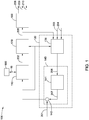
Fig. 1 is a sketch view illustrating a measuring system in accordance with an exemplary embodiment of the present disclosure; -
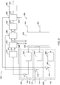
Fig. 2 is a sketch view illustrating a measuring system in accordance with another exemplary embodiment of the present disclosure; -
Fig. 3 is a sketch view illustrating a measuring system in accordance with another exemplary embodiment of the present disclosure; -
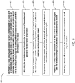
Fig. 4 is a flowchart illustrating a calibration method for calibrating a magnetostrictive sensor in accordance with an exemplary embodiment of the present disclosure; and -
Fig. 5 is a flowchart illustrating a calibration method for calibrating a magnetostrictive sensor in accordance with another exemplary embodiment of the present disclosure. - In an effort to provide a concise description of these embodiments, not all features of an actual implementation are described in one or more specific embodiments. It should be appreciated that in the development of any such actual implementation, as in any engineering or design project, numerous implementation-specific decisions must be made to achieve the developers' specific goals, such as compliance with system-related and business-related constraints, which may vary from one implementation to another. Moreover, it should be appreciated that such a development effort might be complex and time consuming, but would nevertheless be a routine undertaking of design, fabrication, and manufacture for those of ordinary skill having the benefit of the present disclosure.
- Unless defined otherwise, technical and scientific terms used herein have the same meaning as is commonly understood by one of ordinary skill in the art to which the present disclosure belongs. The terms "first," "second," "third," "fourth," and the like, as used herein do not denote any order, quantity, or importance, but rather are used to distinguish one element from another. Also, the terms "a" and "an" do not denote a limitation of quantity, but rather denote the presence of at least one of the referenced items. The term "or" is meant to be inclusive and mean either any, several, or all of the listed items. The use of "including," "comprising," or "having," and variations thereof herein are meant to encompass the items listed thereafter and equivalents thereof as well as additional items.
- Embodiments of the present disclosure refer to a measuring system configured to measure at least one of a stress, a torque and a rotation speed of an object. The measuring system has self-calibration function and can achieve high measuring accuracy.
-
Fig. 1 is a sketch view of ameasuring system 100 for measuring anobject 900 in accordance with an exemplary embodiment of the present disclosure. Referring toFig. 1 , themeasuring system 100 comprises amagnetostrictive sensor 110, acalibration apparatus 120, and acalculator 150. - The
magnetostrictive sensor 110 receives anexcitation signal 201 for generating magnetic flux and outputs anoutput signal 202 which indicates a stress and a torque of the objects. Themagnetostrictive sensor 110 comprises a sensing element positioned adjacent to theobject 900, and there is agap 19 between theobject 900 and thesensing element 110. Theobject 900 may comprise a shaft, a coupling or a combination thereof, and the object has a temperature. Thegap 19 and the temperature may vary during the measuring, which may introduce errors into theoutput signal 202. - The
calibration apparatus 120 is coupled with themagnetostrictive sensor 110 for calibrating theoutput signal 202 of the magnetostrictive sensor, in order to reduce the errors caused by variations in at least one of the gap and the temperature, and thereby increase the measuring accuracy. As shown inFig. 1 , thecalibration apparatus 120 comprises anestimation device 130 and acalibrator 140. - The
estimation device 130 is configured to estimate at least one of thegap 19 and the temperature to obtain at least one of an estimated gap and an estimatedtemperature 206, based on theexcitation signal 201 and theoutput signal 202 of themagnetostrictive sensor 110, geometric information of theobject 203, and geometric information of themagnetostrictive sensor 204. The geometric information of theobject 203 may comprise at least one of a shape and a size of theobject 900. In some embodiments, theobject 900 comprises a shaft, and thegeometric information 203 comprises a diameter of the shaft. The geometric information of themagnetostrictive sensor 204 may comprise at least one of a size and a shape of the sensing element. - In some embodiments, the
excitation signal 201 comprises an alternating excitation signal having a frequency and an amplitude. Theoutput signal 202 comprises an alternating voltage signal, which has an instantaneous amplitude and an instantaneous phase at each moment. Themeasuring system 100 further comprises a lock-indetector 170 for detecting the instantaneous phase and the instantaneous amplitude of the alternating voltage signal. The lock-indetector 170 receives theexcitation signal 201 and theoutput signal 202 of the magnetostrictive sensor, and outputs the instantaneous amplitude and the instantaneous phase of the output signal. The phase and the amplitude of the output signal are usually referred to as animpedance 205 of the output signal. Theestimation device 130 is configured to estimate at least one of an instantaneous gap and an instantaneous temperature based on the frequency and amplitude of the alternating excitation signal, the instantaneous amplitude and the instantaneous phase (i.e.: the instantaneous impedance 205) of the alternating voltage signal, and the geometric information of the object and the sensing element. The alternating excitation signal may comprise an alternating current signal or an alternating voltage signal. - As mentioned above, the
estimation device 130 receives theexcitation signal 201 and theoutput signal 202 of themagnetostrictive sensor 110, geometric information of theobject 203, and geometric information of themagnetostrictive sensor 204, which are referred to as an estimation input, and outputs at least one of the gap and the temperature, which is referred to as an estimation output. In some embodiments, theestimation device 130 estimates the at least one of thegap 19 and the temperature based on an algorithm. The algorithm refers to a relation between the estimation input and the estimation output. The algorithm may comprise a linear model, a nonlinear model, a physical model-based algorithm, a data-driven algorithm, or any combination thereof. The algorithm may comprise an optimal regression model, a neural network based model, an inversed physical model, an extended kalman filter (EKF), an unscented kalman filter (UKF) or any combination thereof. The EKF or UKF is a nonlinear algorithm configured to estimate required quantities based on physical models, input signals and output signals of a system; wherein the physical mode is built based on electro-magnetic principles and the geometric information of the object and the magnetostrictive sensor. Theestimation device 130 may comprise other estimation devices having the similar function. - The
calibrator 140 is configured to reduce or even eliminate an effect on the output signal of the magnetostrictive sensor imposed by the variations in the at least one of the gap and the temperature, based on the at least one of the estimated gap and the estimatedtemperature 206, to obtain a calibrated output signal. Thecalibrator 140 is able to reduce or eliminate the effect in real time, so that theoutput signal 202 is substantially independent of any variations in the gap or the temperature. - Continuing referring to
Fig. 1 , thecalibrator 140 comprises a first adjuster for adjusting theexcitation signal 201 based on the at least one of the estimated gap and the estimatedtemperature 206. Specifically, thefirst adjuster 140 comprises afirst compensation calculator 141 and afirst compensator 142. Thefirst compensation calculator 141 is configured to calculate anexcitation signal compensation 207 based on the at least one of the estimated gap and the estimatedtemperature 206, and thefirst compensator 142 is configured to compensate theexcitation signal 201 according to theexcitation signal compensation 207. In some embodiments, theexcitation signal compensation 207 comprises an amplitude compensation and a frequency compensation. Thefirst compensator 142 compensates the amplitude and the frequency of the excitation signal respectively according to the amplitude compensation and the frequency compensation. In some embodiments, thefirst compensator 142 comprises an adder or a subtracter. - The
calculator 150 is configured to calculate at least one of astress 208 and atorque 209 of the object based on the calibrated output signal. In some embodiments, the object is rotating during the measuring. Thecalculator 150 is also configured to calculate arotation speed 210 of the rotating object based on the calibrated output signal. In the embodiment shown inFig. 1 , thecalculator 150 is configured to calculate thestress 208, thetorque 209 and therotation speed 210 of the object based on theimpedance 205 of the calibrated output signal. -
Fig. 2 is a sketch view of ameasuring system 300 in accordance with another exemplary embodiment of the present disclosure. Referring toFig. 2 , the measuringsystem 300 comprises amagnetostrictive sensor 310, acalibration apparatus 320, acalculator 350 and a lock-indetector 370, which are similar to the corresponding component of thesystem 100. - The
magnetostrictive sensor 310 is positioned adjacent to an object and comprises a plurality of sensing elements (not shown) outputting a plurality ofoutput signals 402 respectively. There is a gap between each sensing element and the object. Each output signal comprises a common-mode part, which will introduce errors into a measured result which comprises at least one of a torque, a stress and a rotation speed of the object. - The lock-in
detector 370 is configured to receive anexcitation signal 401 and the output signals 402 of the magnetostrictive sensor and detect animpedance 412 of each output signal. The impedance used herein refers to a phase and an amplitude of the output signal. - The measuring
system 300 further comprises a common-mode suppression device 360. The common-mode suppression device 360 receives a common-mode suppression signal 411 and is configured to suppress the common-mode parts in the plurality of the output signals based on the common-mode suppression signal 411. The common-mode suppression signal 411 may comprise scaling factors and offsets added to the output signals. In the embodiment illustrated inFig. 2 , the common-mode suppression device 360 receives theimpedances 412 of the output signals from the lock-indetector 370 and outputs processedoutput signals 413 which are free of common-mode signal. - The
calculator 350 is configured to calculate at least one of astress 408, atorque 409 and arotation speed 410 of the object based on the output signals 402. In the embodiment shown inFig. 2 , thecalculator 350 receives the processedoutput signals 413 and outputs thestress 408, thetorque 409 and therotation speed 410 of the object. - The
calibration apparatus 320 comprises anestimation device 330 and a calibration dev
ice 340. Theestimation device 330 is configured to estimate at least one of the temperature and the gaps based on theexcitation signal 401 and the output signals 402 of themagnetostrictive sensor 310, and geometric information of the object and themagnetostrictive sensor gaps 406. The geometric information of themagnetostrictive sensor 404 comprises an amount and arrangement of the sensing elements, and a size and a shape of each sensing element. In the embodiment shown inFig. 2 , theestimation device 330 receives theexcitation signal 401, the impedance of the output signals 412 and the geometric information of the object and themagnetostrictive sensor gaps 406. - The
calibrator 340 is configured to reduce or even eliminate an effect on the output signal imposed by variations in the at least one of the gaps and the temperature, based on the at least one of the estimated gaps and the estimatedtemperature 406, to obtain a calibrated output signal. - Specifically, the
calibrator 340 comprises afirst adjuster 341 and asecond adjuster 344. Thefirst adjuster 341 is configured to adjust theexcitation signal 401 based on the at least one of the estimated gaps and the estimatedtemperature 406. Thefirst adjuster 341 comprises afirst compensation calculator 342 and afirst compensator 343, which have similar functions as thefirst compensation calculator 141 and thefirst compensator 142 illustrated inFig. 1 , and descriptions of which will not be repeated here. - The
second adjuster 344 is configured to adjust the common-mode suppression signal 411 based on the at least one of the estimated gaps and the estimatedtemperature 406. Thesecond adjuster 344 comprises asecond compensation calculator 345 and asecond compensator 346. Thesecond compensation calculator 345 is configured to calculate a common-modesuppression signal compensation 405 based on the at least one of the estimated gap and the estimatedtemperature 406. The second compensator is configured to compensate the common-mode suppression signal 411 according to the common-modesuppression signal compensation 405, to obtain a calibrated common-mode suppression signal. Then, the common-mode suppression device 360 suppresses the common-mode part of the plurality of the output signals based on the calibrated common-mode suppression signal. Each of the first and second compensator may comprise an adder or a subtracter. -
Fig. 3 is a sketch view of ameasuring system 500 for measuring a rotating object in accordance with another exemplary embodiment of the present disclosure. Similar to themeasuring system 300 illustrated inFig. 2 , the measuringsystem 500 comprises amagnetostrictive sensor 510 positioned adjacent to the rotating object and comprising a plurality of sensing elements. There is a gap between each sensing elements and the object. The measuringsystem 500 also comprises a lock-indetector 570, a common-mode suppression device 560, and acalculator 550, which are similar to the corresponding components of themeasuring system 300 and descriptions thereof will not be repeated here. - The measuring
system 500 further comprises arunout compensator 580 for reducing or even eliminating an effect of runout on a measuredresult 608, wherein the measuredresult 608 comprises at least one of a torque, a stress and a rotation speed. The runout used herein refers to a sum of variations of surface hardness, surface roughness, residual stress and other sources causing inhomogeneity in electromagnetic property in a case of zero torque. The runout may vary with the rotating of the object, and a relation between the runout and a shaft angular location (indicating an instantaneous rotating location of the object) is referred to as arunout model 621. Referring toFig. 3 , therunout compensator 580 is coupled with thecalculator 550 for calibrating the measuredresult 608 according to therunout model 621 and the shaftangular location 622, to obtain a first calibrated measuredresult 609. In some embodiments, therunout compensator 580 is configured to calibrate the measured result in real time, according to the runout model and a real time shaft angular location of the object. - The measuring
system 500 further comprises ahysteresis compensator 590 for reducing or elimanating hysteresis effect on the measuredresult 608. In the embodiment shown inFig. 3 , thehysteresis compensator 590 is coupled with therunout compensator 580 for reducing or elimanating hysteresis effect on the first calibrated measuredresult 609 to obtain a second calibrated measuredresult 610. - The
calibration apparatus 520 comprises anestimation device 530 and acalibrator 540. Similar to theestimation device 330 of themeasuring system 300, theestimation device 530 is configured to estimate at least one of the gaps and a temperature of the object, based on anexcitation signal 601 andoutput signals 602 of themagnetostrictive sensor 510, and geometric information of the object and themagnetostrictive sensor gaps 606. - The
calibrator 540 comprises afirst adjuster 541 and asecond adjuster 544. Thefirst adjuster 541 comprises afirst compensation calculator 542 and afirst compensator 543. Thesecond adjuster 544 comprises asecond compensation calculator 545 and asecond compensator 546. Thefirst compensation calculator 542, thefirst compensator 543, thesecond compensation calculator 545 and thesecond compensator 546 are similar to the corresponding components of themeasuring system 300, and descriptions thereof will not be repeated here. - The
calibrator 540 further comprises athird adjuster 547 for adjusting therunout model 621 inputted into therunout compensator 580. Thethird adjuster 547 comprises athird compensation calculator 548 and athird compensator 549. Thethird compensation calculator 548 is configured to calculate arunout model compensation 620 based on at least one of the estimated temperature and the estimatedgaps 606. Thethird compensator 549 is configured to compensate therunout model 621 according to therunout model compensation 620 to obtain a calibrated runout model. Then therunout compensator 580 calibrates the measured result based on the calibrated runout model. - In some embodiments, the object is a drive shaft of a machine such as an electric drive train and a turbomachinery. The torque and the rotation speed of the object may also be estimated based on some machine signals to obtain an estimated result, wherein the machine signals comprise electrical current or voltage signals from the electric drive train, or pressure or temperature signals from the turbomachinery. The measured result from the measuring system can be compared with the estimated result based on the machine signals. If a difference between the two results is higher than a preset threshold value, the magnetostrictive sensor may be replaced, or algorithm of at least one of the estimation device, the adjusters, the common-mode suppression device and the calculator may be adjusted.
- Embodiments of the present disclosure also refer to a method for calibrating a magnetostrictive sensor, where in the magnetostrictive sensor is configured to measure at least one of a stress, a torque and a rotation speed of an object. The method is able to estimate a magnetic gap and a temperature of the object rather than measure them directly, in such a manner that system design can be simplified and a measuring speed can be increased.
-
Fig. 4 is a flowchart illustrating amethod 700 for calibrating a magnetostrictive sensor in accordance with an exemplary embodiment of the present disclosure. The magnetostrictive sensor is configured to measure an object. The magnetostrictive sensor comprises a sensing element adjacent to the object. Referring toFig. 4 , themethod 700 comprisesstep 701 to step 705. - In
step 701, at least one of a gap between the sensing element and the object and a temperature of the object is estimated to obtain at least one of an estimated gap and an estimated temperature, based on geometric information, an excitation signal and an output signal of the magnetostrictive sensor, and geometric information of the object. In some embodiments, the at least one of the gap and the temperature is estimated based on an algorithm. The algorithm may comprise a linear model, a nonlinear model, a physical model-based algorithm, a data-driven algorithm, or any combination thereof. The algorithm may comprise an optimal regression model, a neural network based model, an inversed physical model, an extended kalman filter (EKF), an unscented kalman filter (UKF), or any combination thereof. - Steps 703-705 relate to reducing an effect on the output signal of the magnetostrictive sensor imposed by variations in the at least one of the gap and the temperature based on the at least one of the estimated gap and the estimated temperature, to obtain a calibrated output signal. In some embodiments, the effect can be reduced by adjusting the excitation signal based on the at least one of the estimated gap and the estimated temperature. Specifically, the adjusting the excitation signal comprises
step 703 andstep 705. - In
step 703, an excitation signal compensation is calculated based on the at least one of the estimated gap and the estimated temperature. - In
step 705, the excitation signal is compensated according to the excitation signal compensation. - In some embodiment, the magnetostrictive sensor comprises a plurality of sensing elements, which output a plurality of output signals respectively. Each of the output signals comprises a common-mode part, which will introduce errors into the measured result. Therefore, the calibrating method may comprise a step of suppressing the common-mode parts of the plurality of output signals based on a common-mode suppression signal. The calibrating method may further comprise a step of reducing a runout effect on the measured result based on a runout model and a shaft angular location.
-
Fig. 5 shows a flowchart of acalibration method 800 for calibrating a magnetostrictive sensor in accordance with the above-mentioned embodiments. While actions of the method are illustrated as functional blocks, the order of the blocks and the separation of the actions among the various blocks shown inFig. 5 are not intended to be limiting. For example, the blocks maybe performed in a different order and an action associated with one block may be combined with one or more other blocks or maybe sub-divided into a number of blocks. - As mentioned above, the magnetostrictive sensor comprises the plurality of sensing elements. The magnetostrictive sensor is positioned adjacent to an object with a gap between each sensing element and the object, and each of the sensing elements outputs an output signal. Referring to
Fig. 5 , thecalibration method 800 comprisesstep 801 to step 811. - In
step 801, at least one of the gaps and a temperature of the object are estimated to obtain at least one of estimated gaps and an estimated temperature, based on geometric information, an excitation signal and the plurality of output signals of the magnetostrictive sensor, and geometric information of the object. - In
step 803, the excitation signal is adjusted based on the at least one of the estimated gaps and the estimated temperature, in order to reduce an effect on the output signals imposed by variations in the at least one of the gaps and the temperature. In some embodiments, the adjusting the excitation signal comprises calculating an excitation signal compensation based on the at least one of the estimated gaps and the estimated temperature, and compensating the excitation signal according to the excitation signal compensation. - In
step 805, the common-mode suppression signal is adjusted based on the at least one of the estimated gaps and the estimated temperature to obtained a calibrated common-mode suppression signal. In some embodiments, the adjusting the common-mode suppression signal comprises calculating a common-mode suppression signal compensation based on the at least one of the estimated gaps and the estimated temperature, and compensating the common-mode suppression signal according to the common-mode suppression signal compensation. - Step 807 relates to suppressing the common-mode part of the plurality of output signals based on the calibrated common-mode suppression signal.
- In
step 809, the runout model is adjusted based on the at least one of the estimated gaps and the estimated temperature to obtain a calibrated runout model. In some embodiments, the adjustment of the runout model comprises calculating a runout model compensation based on the at least one of the estimated gaps and the estimated temperature, and compensating the runout model according to the runout model compensation. - Step 811 relates to reducing the runout effect based on the calibrated runout model and the shaft angular location.
- Details of the methods may be similar to these of the processes described herein above in conjunction with the measuring system, and will not be repeated.
- As will be understood by those familiar with the art, the present disclosure may be embodied in other specific forms without depending from the spirit or essential characteristics thereof. Accordingly, the disclosures and descriptions herein are intended to be illustrative, but not limiting, of the scope of the disclosure which is set forth in the following claims.
- Various aspects and embodiments of the present invention are defined by the following clauses:
- 1. A calibration apparatus for calibrating a magnetostrictive sensor, which is configured to measure an object and comprises a sensing element positioned adjacent to the object, the calibration apparatus comprising:
- an estimation device for estimating at least one of a gap between the sensing element and the object and a temperature of the object to obtain at least one of an estimated gap and an estimated temperature, based on geometric information, an excitation signal and an output signal of the magnetostrictive sensor, and geometric information of the object; and
- a calibrator for reducing an effect on the output signal of the magnetostrictive sensor imposed by variations in the at least one of the gap and the temperature based on the at least one of the estimated gap and the estimated temperature, to obtain a calibrated output signal.
- 2. The calibration apparatus according to clause 1, wherein the calibrator comprises a first adjuster for adjusting the excitation signal based on the at least one of the estimated gap and the estimated temperature.
- 3. The calibration apparatus according to clause 1 or 2, wherein the first adjuster comprises:
- a first compensation calculator for calculating an excitation signal compensation based on the at least one of the estimated gap and the estimated temperature; and
- a first compensator for compensating the excitation signal according to the excitation signal compensation.
- 4. The calibration apparatus according to any preceding clause, wherein the magnetostrictive sensor comprises a plurality of sensing elements which output a plurality of output signals respectively, the estimation device is configured to estimate at least one of gaps between the sensing elements and the object and the temperature of the object to obtain at least one of estimated gaps and the estimated temperature, and the calibration apparatus further comprises a common-mode suppression device for suppressing a common-mode part of the plurality of output signals based on a common-mode suppression signal.
- 5. The calibration apparatus according to any preceding clause, wherein the calibrator comprises a second adjuster for adjusting the common-mode suppression signal based on the at least one of the estimated gaps and the estimated temperature.
- 6. The calibration apparatus according to any preceding clause, wherein the second adjuster comprises:
- a second compensation calculator for calculating a common-mode suppression signal compensation based on the at least one of the estimated gaps and the estimated temperature; and
- a second compensator for compensating the common-mode suppression signal according to the common-mode suppression signal compensation.
- 7. The calibration apparatus according to any preceding clause, wherein the estimation device is configured to estimate the at least one of the gap and the temperature based on an algorithm, and the algorithm comprises a linear model, a nonlinear model, a physical model-based algorithm, a data-driven algorithm, or any combination thereof.
- 8. The calibration apparatus according to any preceding clause, wherein the estimation device is configured to estimate the at least one of the gap and the temperature based on an algorithm, and the algorithm comprises an optimal regression model, a neural network based model, an inversed physical model, an extended kalman filter (EKF), an unscented kalman filter (UKF), or any combination thereof.
- 9. A measuring system for measuring an object, comprising:
- a magnetostrictive sensor comprising a sensing element positioned adjacent to the object;
- an estimation device for estimating at least one of a gap between the sensing element and the object and a temperature of the object to obtain at least one of an estimated gap and an estimated temperature, based on geometric information, an excitation signal and an output signal of the magnetostrictive sensor, and geometric information of the object;
- a calibrator for reducing an effect on the output signal of the magnetostrictive sensor imposed by variations in the at least one of the gap and the temperature based on the at least one of the estimated gap and the estimated temperature, to obtain a calibrated output signal; and
- a calculator for calculating at least one of a stress, a torque and a rotation speed of the object, based on the calibrated output signal.
- 10. The measuring system according to any preceding clause, wherein the estimation device is configured to estimate the at least one of the gap and the temperature based on an algorithm, and the algorithm comprises a linear model, a nonlinear model, a physical model-based algorithm, a data-driven algorithm, or any combination thereof.
- 11. The measuring system according to any preceding clause, wherein the estimation device is configured to estimate the at least one of the gap and the temperature based on an algorithm, and the algorithm comprises an optimal regression model, a neural network based model, an inversed physical model, an extended kalman filter (EKF), an unscented kalman filter (UKF), or any combination thereof.
- 12. A calibration method for calibrating a magnetostrictive sensor, which is configured to measure an object and comprises a sensing element adjacent to the object, the calibration method comprising:
- estimating at least one of a gap between the sensing element and the object and a temperature of the object to obtain at least one of an estimated gap and an estimated temperature, based on geometric information, an excitation signal and an output signal of the magnetostrictive sensor, and geometric information of the object; and
- reducing an effect on the output signal of the magnetostrictive sensor imposed by variations in the at least one of the gap and the temperature based on the at least one of the estimated gap and the estimated temperature, to obtain a calibrated output signal.
- 13. The calibration method according to any preceding clause, wherein the reducing the effect comprises adjusting the excitation signal based on the at least one of the estimated gap and the estimated temperature.
- 14. The calibration method according to any preceding clause, wherein the adjusting the excitation signal comprises:
- calculating an excitation signal compensation based on the at least one of the estimated gap and the estimated temperature; and
- compensating the excitation signal according to the excitation signal compensation.
- 15. The calibration method according to any preceding clause, wherein the magnetostrictive sensor comprises a plurality of sensing elements which output a plurality of output signals respectively, the step of estimating comprises estimating at least one of gaps between the plurality of sensing elements and the object and the temperature of the object to obtain at least one of estimated gaps and the estimated temperature, and the method further comprises suppressing a common-mode part of the plurality of output signals based on a common-mode suppression signal.
- 16. The calibration method according to any preceding clause, wherein the reducing the effect comprises adjusting the common-mode suppression signal based on the at least one of the estimated gaps and the estimated temperature.
- 17. The calibration method according to any preceding clause, wherein the adjusting the common-mode suppression signal comprises:
- calculating a common-mode suppression signal compensation based on the at least one of the estimated gaps and the estimated temperature; and
- compensating the common-mode suppression signal according to the common-mode suppression signal compensation.
- 18. The calibration method according to any preceding clause, wherein the estimating comprises estimating the at least one of the gap and the temperature based on an algorithm, and the algorithm comprises a linear model, a nonlinear model, a physical model-based algorithm, a data-driven algorithm, or any combination thereof.
- 19. The calibration method according to any preceding clause, wherein the estimating comprises estimating the at least one of the gap and the temperature based on an algorithm, and the algorithm comprises an optimal regression model, a neural network based model, an inversed physical model, an extended kalman filter (EKF), an unscented kalman filter (UKF), or any combination thereof.
Claims (15)
- A calibration apparatus for calibrating a magnetostrictive sensor, which is configured to measure an object and comprises a sensing element positioned adjacent to the object, the calibration apparatus comprising:an estimation device for estimating at least one of a gap between the sensing element and the object and a temperature of the object to obtain at least one of an estimated gap and an estimated temperature, based on geometric information, an excitation signal and an output signal of the magnetostrictive sensor, and geometric information of the object; anda calibrator for reducing an effect on the output signal of the magnetostrictive sensor imposed by variations in the at least one of the gap and the temperature based on the at least one of the estimated gap and the estimated temperature, to obtain a calibrated output signal.
- The calibration apparatus according to claim 1, wherein the calibrator comprises a first adjuster for adjusting the excitation signal based on the at least one of the estimated gap and the estimated temperature.
- The calibration apparatus according to claim 1 or 2, wherein the magnetostrictive sensor comprises a plurality of sensing elements which output a plurality of output signals respectively, the estimation device is configured to estimate at least one of gaps between the sensing elements and the object and the temperature of the object to obtain at least one of estimated gaps and the estimated temperature, and the calibration apparatus further comprises a common-mode suppression device for suppressing a common-mode part of the plurality of output signals based on a common-mode suppression signal.
- The calibration apparatus according to claim 1, 2 or 3, wherein the estimation device is configured to estimate the at least one of the gap and the temperature based on an algorithm, and the algorithm comprises a linear model, a nonlinear model, a physical model-based algorithm, a data-driven algorithm, or any combination thereof.
- The calibration apparatus according to claim 1, 2 or 3, wherein the estimation device is configured to estimate the at least one of the gap and the temperature based on an algorithm, and the algorithm comprises an optimal regression model, a neural network based model, an inversed physical model, an extended kalman filter (EKF), an unscented kalman filter (UKF), or any combination thereof.
- A measuring system for measuring an object, comprising:a magnetostrictive sensor comprising a sensing element positioned adjacent to the object;an estimation device for estimating at least one of a gap between the sensing element and the object and a temperature of the object to obtain at least one of an estimated gap and an estimated temperature, based on geometric information, an excitation signal and an output signal of the magnetostrictive sensor, and geometric information of the object;a calibrator for reducing an effect on the output signal of the magnetostrictive sensor imposed by variations in the at least one of the gap and the temperature based on the at least one of the estimated gap and the estimated temperature, to obtain a calibrated output signal; anda calculator for calculating at least one of a stress, a torque and a rotation speed of the object, based on the calibrated output signal.
- The measuring system according to claim 6, wherein the estimation device is configured to estimate the at least one of the gap and the temperature based on an algorithm, and the algorithm comprises a linear model, a nonlinear model, a physical model-based algorithm, a data-driven algorithm, or any combination thereof.
- The measuring system according to claim 6, wherein the estimation device is configured to estimate the at least one of the gap and the temperature based on an algorithm, and the algorithm comprises an optimal regression model, a neural network based model, an inversed physical model, an extended kalman filter (EKF), an unscented kalman filter (UKF), or any combination thereof.
- A calibration method for calibrating a magnetostrictive sensor, which is configured to measure an object and comprises a sensing element adjacent to the object, the calibration method comprising:estimating at least one of a gap between the sensing element and the object and a temperature of the object to obtain at least one of an estimated gap and an estimated temperature, based on geometric information, an excitation signal and an output signal of the magnetostrictive sensor, and geometric information of the object; andreducing an effect on the output signal of the magnetostrictive sensor imposed by variations in the at least one of the gap and the temperature based on the at least one of the estimated gap and the estimated temperature, to obtain a calibrated output signal.
- The calibration method according to claim 9, wherein the reducing the effect comprises adjusting the excitation signal based on the at least one of the estimated gap and the estimated temperature.
- The calibration method according to claim 10, wherein the adjusting the excitation signal comprises:calculating an excitation signal compensation based on the at least one of the estimated gap and the estimated temperature; andcompensating the excitation signal according to the excitation signal compensation.
- The calibration method according to any of claims 9 to 11, wherein the magnetostrictive sensor comprises a plurality of sensing elements which output a plurality of output signals respectively, the step of estimating comprises estimating at least one of gaps between the plurality of sensing elements and the object and the temperature of the object to obtain at least one of estimated gaps and the estimated temperature, and the method further comprises suppressing a common-mode part of the plurality of output signals based on a common-mode suppression signal.
- The calibration method according to claim 12, wherein the reducing the effect comprises adjusting the common-mode suppression signal based on the at least one of the estimated gaps and the estimated temperature.
- The calibration method according to any of claims 9 to 13, wherein the estimating comprises estimating the at least one of the gap and the temperature based on an algorithm, and the algorithm comprises a linear model, a nonlinear model, a physical model-based algorithm, a data-driven algorithm, or any combination thereof.
- The calibration method according to any of claims 9 to 13, wherein the estimating comprises estimating the at least one of the gap and the temperature based on an algorithm, and the algorithm comprises an optimal regression model, a neural network based model, an inversed physical model, an extended kalman filter (EKF), an unscented kalman filter (UKF), or any combination thereof.
Applications Claiming Priority (1)
| Application Number | Priority Date | Filing Date | Title |
|---|---|---|---|
| CN201610873914.8A CN107884099B (en) | 2016-09-30 | 2016-09-30 | Calibration device, calibration method and measurement system |
Publications (2)
| Publication Number | Publication Date |
|---|---|
| EP3301426A1 true EP3301426A1 (en) | 2018-04-04 |
| EP3301426B1 EP3301426B1 (en) | 2021-04-28 |
Family
ID=59930238
Family Applications (1)
| Application Number | Title | Priority Date | Filing Date |
|---|---|---|---|
| EP17192362.6A Active EP3301426B1 (en) | 2016-09-30 | 2017-09-21 | Calibration apparatus, calibration method, and measuring system |
Country Status (4)
| Country | Link |
|---|---|
| US (1) | US10809315B2 (en) |
| EP (1) | EP3301426B1 (en) |
| CN (1) | CN107884099B (en) |
| DK (1) | DK3301426T3 (en) |
Cited By (2)
| Publication number | Priority date | Publication date | Assignee | Title |
|---|---|---|---|---|
| CN110829885A (en) * | 2019-11-22 | 2020-02-21 | 温州大学 | A mechanical impedance matching control method for a magnetostrictive precision drive device |
| CN113820062A (en) * | 2021-09-30 | 2021-12-21 | 浙江大学 | Temperature compensation method of six-dimensional force sensor |
Families Citing this family (6)
| Publication number | Priority date | Publication date | Assignee | Title |
|---|---|---|---|---|
| CN111278613B (en) * | 2017-11-02 | 2022-10-04 | 三菱电机株式会社 | Calibration device, calibration method, and control device |
| CN109781341B (en) * | 2018-12-25 | 2021-10-08 | 潍坊歌尔微电子有限公司 | Data calibration method and device for air pressure sensor |
| CN111380648A (en) * | 2020-03-27 | 2020-07-07 | 辛成辉 | Self-calibration pressure sensor and self-calibration method thereof |
| CN111982194B (en) * | 2020-08-18 | 2023-03-28 | 成都一通密封股份有限公司 | Wireless pressure and temperature integrated sensor |
| CN115219081B (en) * | 2022-07-07 | 2025-03-04 | 黑龙江大学 | Temperature compensation method of optical fiber pressure sensor based on fusion of neural network and Kalman filter |
| CN120233119A (en) * | 2025-06-03 | 2025-07-01 | 创值汽车配件(上海)有限公司 | A method and system for calibrating an automobile sensor |
Citations (3)
| Publication number | Priority date | Publication date | Assignee | Title |
|---|---|---|---|---|
| US20140165737A1 (en) * | 2011-08-02 | 2014-06-19 | Siemens Aktiengesellschaft | Method and measuring device for investigating a magnetic workpiece |
| US20140184210A1 (en) * | 2012-12-28 | 2014-07-03 | General Electric Company | Non-contact magnetostrictive sensing systems and methods |
| EP2833109A1 (en) * | 2013-07-31 | 2015-02-04 | Bayern Engineering GmbH & Co. KG | Measurement apparatus with compensation |
Family Cites Families (24)
| Publication number | Priority date | Publication date | Assignee | Title |
|---|---|---|---|---|
| US4011758A (en) * | 1973-12-26 | 1977-03-15 | Texas Instruments Incorporated | Magnetostrictive pressure transducer |
| JPH0754273B2 (en) * | 1987-12-26 | 1995-06-07 | 大同特殊鋼株式会社 | Torxense |
| US5062062A (en) * | 1988-12-30 | 1991-10-29 | Kabushiki Kaisha Toyota Chuo Kenkyusho | Torque detecting apparatus |
| US5269178A (en) | 1990-12-10 | 1993-12-14 | Sensortech, L.P. | Engine misfire, knock of roughness detection method and apparatus |
| US5495774A (en) | 1993-06-10 | 1996-03-05 | Sensortech L.P. | Magnetostrictive torque sensor air gap compensator |
| US5351555A (en) | 1991-07-29 | 1994-10-04 | Magnetoelastic Devices, Inc. | Circularly magnetized non-contact torque sensor and method for measuring torque using same |
| US5274328A (en) * | 1992-07-20 | 1993-12-28 | Magnetek Inc. | Temperature compensation for magnetostrictive position detector |
| US6208133B1 (en) * | 1998-10-01 | 2001-03-27 | Balluff, Inc. | Method and apparatus for calibrating the output signal of a linear position detector |
| US6351117B1 (en) * | 1999-09-20 | 2002-02-26 | Balluff, Inc. | Method and apparatus for generating transducer output pulses compensated for component variations |
| CN101308200A (en) * | 2002-11-29 | 2008-11-19 | 雅马哈株式会社 | Magnetic sensor and method for compensating magnetic sensor temperature correlated characteristic |
| BRPI0501790B1 (en) * | 2005-05-17 | 2019-02-12 | Petroleo Brasileiro S.A. - Petrobras | SYSTEMS WITH REMOTE FIBER OPTICAL POSITION TRANSDUCER AND POSITION CALIBRATION METHOD |
| US7261005B2 (en) * | 2005-08-11 | 2007-08-28 | Honeywell International Inc. | Magneto-elastic resonator torque sensor |
| US7454978B2 (en) * | 2005-11-16 | 2008-11-25 | Delphi Technologies, Inc. | Versatile strain sensor employing magnetostrictive electrical conductors |
| US7997152B2 (en) | 2007-01-02 | 2011-08-16 | Azuma Shokai Co., Ltd. | Magnetostrictive torque sensor and torque detection method |
| US7533584B1 (en) | 2007-11-12 | 2009-05-19 | Honeywell International Inc. | Systems and methods for temperature compensating torque sensors |
| CN101387522B (en) * | 2008-09-02 | 2011-04-27 | 吉林大学 | Magnetic guide sensor |
| US8352149B2 (en) | 2008-10-02 | 2013-01-08 | Honeywell International Inc. | System and method for providing gas turbine engine output torque sensor validation and sensor backup using a speed sensor |
| US8001849B2 (en) * | 2009-03-28 | 2011-08-23 | Wensheng Weng | Self-compensating magnetoelastic torque sensor system |
| US8203334B2 (en) | 2010-10-28 | 2012-06-19 | General Electric Company | Magnetically spirally encoded shaft for measuring rotational angel, rotational speed and torque |
| US9383273B2 (en) * | 2011-05-24 | 2016-07-05 | Ford Global Technologies, Llc | Magnetic torque sensor packaging for automatic transmissions |
| EP2615439A1 (en) * | 2012-01-13 | 2013-07-17 | Siemens Aktiengesellschaft | Magneto-elastic force sensor and method for compensating for a function of distance in a measurement signal of such a sensor |
| US10094720B2 (en) * | 2014-04-10 | 2018-10-09 | General Electric Company | System and method of magnetic shielding for sensors |
| US9435708B1 (en) * | 2015-06-16 | 2016-09-06 | Magcanica, Inc. | Devices and methods to enhance accuracy of magnetoelastic torque sensors |
| US10473536B2 (en) * | 2017-08-11 | 2019-11-12 | Bently Nevada, Llc | Gap compensation for magnetostrictive torque sensors |
-
2016
- 2016-09-30 CN CN201610873914.8A patent/CN107884099B/en not_active Expired - Fee Related
-
2017
- 2017-09-19 US US15/708,455 patent/US10809315B2/en active Active
- 2017-09-21 EP EP17192362.6A patent/EP3301426B1/en active Active
- 2017-09-21 DK DK17192362.6T patent/DK3301426T3/en active
Patent Citations (3)
| Publication number | Priority date | Publication date | Assignee | Title |
|---|---|---|---|---|
| US20140165737A1 (en) * | 2011-08-02 | 2014-06-19 | Siemens Aktiengesellschaft | Method and measuring device for investigating a magnetic workpiece |
| US20140184210A1 (en) * | 2012-12-28 | 2014-07-03 | General Electric Company | Non-contact magnetostrictive sensing systems and methods |
| EP2833109A1 (en) * | 2013-07-31 | 2015-02-04 | Bayern Engineering GmbH & Co. KG | Measurement apparatus with compensation |
Cited By (5)
| Publication number | Priority date | Publication date | Assignee | Title |
|---|---|---|---|---|
| CN110829885A (en) * | 2019-11-22 | 2020-02-21 | 温州大学 | A mechanical impedance matching control method for a magnetostrictive precision drive device |
| US20210159386A1 (en) * | 2019-11-22 | 2021-05-27 | Wenzhou University | Matching control method for mechanical impedance of magnetostrictive precision transducer |
| CN110829885B (en) * | 2019-11-22 | 2022-10-21 | 温州大学 | A mechanical impedance matching control method for a magnetostrictive precision drive device |
| US11778916B2 (en) * | 2019-11-22 | 2023-10-03 | Wenzhou University | Matching control method for mechanical impedance of magnetostrictive precision transducer |
| CN113820062A (en) * | 2021-09-30 | 2021-12-21 | 浙江大学 | Temperature compensation method of six-dimensional force sensor |
Also Published As
| Publication number | Publication date |
|---|---|
| DK3301426T3 (en) | 2021-06-28 |
| US10809315B2 (en) | 2020-10-20 |
| US20180095144A1 (en) | 2018-04-05 |
| CN107884099B (en) | 2020-08-11 |
| EP3301426B1 (en) | 2021-04-28 |
| CN107884099A (en) | 2018-04-06 |
Similar Documents
| Publication | Publication Date | Title |
|---|---|---|
| EP3301426B1 (en) | Calibration apparatus, calibration method, and measuring system | |
| KR101664567B1 (en) | Apparatus and Method for Compensating Position Information Error of Resolver | |
| TW201531726A (en) | Temperature compensation method of magnetic control fields in a hall sensor with os adaption | |
| US20180172779A1 (en) | Method for Offset Compensation of a Sensor Signal of a Hall Sensor and Sensor Arrangement | |
| US10416209B2 (en) | Method and system for measuring power loss in a power transformer | |
| US20190310111A1 (en) | Magnetic sensor system for measuring linear position | |
| US9035648B2 (en) | Magnetic sensor characterization | |
| CN111133279A (en) | Method for compensating for disturbances of a measured angle signal of a magnetic angle sensor of an electric machine, correspondingly designed microcontroller, electric machine and computer program product | |
| KR20190018844A (en) | Apparatus and method for compensating position error of resolver | |
| CN112484632B (en) | Device and method for determining a rotation angle | |
| US8872530B2 (en) | Method for correcting the voltage measured across the terminals of a sensor | |
| US20240344870A1 (en) | Method for operating a coriolis measurement device | |
| CN105765337B (en) | Inductive measuring probe and method for operating an inductive measuring probe | |
| JP4797609B2 (en) | Method for correcting temperature characteristics of rotation angle detection device and rotation angle detection device | |
| JP2015161534A (en) | Electromagnetic flowmeter, flow rate measurement system, and flow rate calculation method | |
| US9267814B2 (en) | System and process for determining offsets of measuring instruments | |
| US12313435B2 (en) | Method for operating a Coriolis measurement device | |
| JP2018025398A (en) | Electromagnetic induction position detector | |
| KR101891414B1 (en) | Measurement Method and Apparatus for Simultaneous Correction of Sensor Disturbance and Offset | |
| CN105071718A (en) | Rotor position error calibration apparatus and method for brushless motor | |
| KR101075027B1 (en) | Sensor offset compensate circuit and method of thereof | |
| JP2009527209A (en) | Method for detecting the inductance of an electric motor | |
| JP2011180009A (en) | Position sensor and position detection method | |
| JP6673175B2 (en) | Induction motor control system | |
| CN115280114B (en) | Method for operating a Coriolis measuring device |
Legal Events
| Date | Code | Title | Description |
|---|---|---|---|
| PUAI | Public reference made under article 153(3) epc to a published international application that has entered the european phase |
Free format text: ORIGINAL CODE: 0009012 |
|
| STAA | Information on the status of an ep patent application or granted ep patent |
Free format text: STATUS: THE APPLICATION HAS BEEN PUBLISHED |
|
| AK | Designated contracting states |
Kind code of ref document: A1 Designated state(s): AL AT BE BG CH CY CZ DE DK EE ES FI FR GB GR HR HU IE IS IT LI LT LU LV MC MK MT NL NO PL PT RO RS SE SI SK SM TR |
|
| AX | Request for extension of the european patent |
Extension state: BA ME |
|
| STAA | Information on the status of an ep patent application or granted ep patent |
Free format text: STATUS: REQUEST FOR EXAMINATION WAS MADE |
|
| 17P | Request for examination filed |
Effective date: 20181004 |
|
| RBV | Designated contracting states (corrected) |
Designated state(s): AL AT BE BG CH CY CZ DE DK EE ES FI FR GB GR HR HU IE IS IT LI LT LU LV MC MK MT NL NO PL PT RO RS SE SI SK SM TR |
|
| STAA | Information on the status of an ep patent application or granted ep patent |
Free format text: STATUS: EXAMINATION IS IN PROGRESS |
|
| 17Q | First examination report despatched |
Effective date: 20190322 |
|
| GRAP | Despatch of communication of intention to grant a patent |
Free format text: ORIGINAL CODE: EPIDOSNIGR1 |
|
| STAA | Information on the status of an ep patent application or granted ep patent |
Free format text: STATUS: GRANT OF PATENT IS INTENDED |
|
| INTG | Intention to grant announced |
Effective date: 20201111 |
|
| GRAS | Grant fee paid |
Free format text: ORIGINAL CODE: EPIDOSNIGR3 |
|
| GRAA | (expected) grant |
Free format text: ORIGINAL CODE: 0009210 |
|
| STAA | Information on the status of an ep patent application or granted ep patent |
Free format text: STATUS: THE PATENT HAS BEEN GRANTED |
|
| AK | Designated contracting states |
Kind code of ref document: B1 Designated state(s): AL AT BE BG CH CY CZ DE DK EE ES FI FR GB GR HR HU IE IS IT LI LT LU LV MC MK MT NL NO PL PT RO RS SE SI SK SM TR |
|
| REG | Reference to a national code |
Ref country code: GB Ref legal event code: FG4D |
|
| REG | Reference to a national code |
Ref country code: CH Ref legal event code: EP |
|
| REG | Reference to a national code |
Ref country code: AT Ref legal event code: REF Ref document number: 1387584 Country of ref document: AT Kind code of ref document: T Effective date: 20210515 |
|
| REG | Reference to a national code |
Ref country code: DE Ref legal event code: R096 Ref document number: 602017037482 Country of ref document: DE |
|
| REG | Reference to a national code |
Ref country code: IE Ref legal event code: FG4D |
|
| REG | Reference to a national code |
Ref country code: DK Ref legal event code: T3 Effective date: 20210623 |
|
| REG | Reference to a national code |
Ref country code: SE Ref legal event code: TRGR |
|
| REG | Reference to a national code |
Ref country code: LT Ref legal event code: MG9D |
|
| REG | Reference to a national code |
Ref country code: AT Ref legal event code: MK05 Ref document number: 1387584 Country of ref document: AT Kind code of ref document: T Effective date: 20210428 |
|
| PG25 | Lapsed in a contracting state [announced via postgrant information from national office to epo] |
Ref country code: AT Free format text: LAPSE BECAUSE OF FAILURE TO SUBMIT A TRANSLATION OF THE DESCRIPTION OR TO PAY THE FEE WITHIN THE PRESCRIBED TIME-LIMIT Effective date: 20210428 Ref country code: BG Free format text: LAPSE BECAUSE OF FAILURE TO SUBMIT A TRANSLATION OF THE DESCRIPTION OR TO PAY THE FEE WITHIN THE PRESCRIBED TIME-LIMIT Effective date: 20210728 Ref country code: HR Free format text: LAPSE BECAUSE OF FAILURE TO SUBMIT A TRANSLATION OF THE DESCRIPTION OR TO PAY THE FEE WITHIN THE PRESCRIBED TIME-LIMIT Effective date: 20210428 Ref country code: NL Free format text: LAPSE BECAUSE OF FAILURE TO SUBMIT A TRANSLATION OF THE DESCRIPTION OR TO PAY THE FEE WITHIN THE PRESCRIBED TIME-LIMIT Effective date: 20210428 Ref country code: FI Free format text: LAPSE BECAUSE OF FAILURE TO SUBMIT A TRANSLATION OF THE DESCRIPTION OR TO PAY THE FEE WITHIN THE PRESCRIBED TIME-LIMIT Effective date: 20210428 Ref country code: LT Free format text: LAPSE BECAUSE OF FAILURE TO SUBMIT A TRANSLATION OF THE DESCRIPTION OR TO PAY THE FEE WITHIN THE PRESCRIBED TIME-LIMIT Effective date: 20210428 |
|
| PG25 | Lapsed in a contracting state [announced via postgrant information from national office to epo] |
Ref country code: LV Free format text: LAPSE BECAUSE OF FAILURE TO SUBMIT A TRANSLATION OF THE DESCRIPTION OR TO PAY THE FEE WITHIN THE PRESCRIBED TIME-LIMIT Effective date: 20210428 Ref country code: IS Free format text: LAPSE BECAUSE OF FAILURE TO SUBMIT A TRANSLATION OF THE DESCRIPTION OR TO PAY THE FEE WITHIN THE PRESCRIBED TIME-LIMIT Effective date: 20210828 Ref country code: GR Free format text: LAPSE BECAUSE OF FAILURE TO SUBMIT A TRANSLATION OF THE DESCRIPTION OR TO PAY THE FEE WITHIN THE PRESCRIBED TIME-LIMIT Effective date: 20210729 Ref country code: PT Free format text: LAPSE BECAUSE OF FAILURE TO SUBMIT A TRANSLATION OF THE DESCRIPTION OR TO PAY THE FEE WITHIN THE PRESCRIBED TIME-LIMIT Effective date: 20210830 Ref country code: NO Free format text: LAPSE BECAUSE OF FAILURE TO SUBMIT A TRANSLATION OF THE DESCRIPTION OR TO PAY THE FEE WITHIN THE PRESCRIBED TIME-LIMIT Effective date: 20210728 Ref country code: PL Free format text: LAPSE BECAUSE OF FAILURE TO SUBMIT A TRANSLATION OF THE DESCRIPTION OR TO PAY THE FEE WITHIN THE PRESCRIBED TIME-LIMIT Effective date: 20210428 Ref country code: RS Free format text: LAPSE BECAUSE OF FAILURE TO SUBMIT A TRANSLATION OF THE DESCRIPTION OR TO PAY THE FEE WITHIN THE PRESCRIBED TIME-LIMIT Effective date: 20210428 |
|
| REG | Reference to a national code |
Ref country code: NL Ref legal event code: MP Effective date: 20210428 |
|
| PG25 | Lapsed in a contracting state [announced via postgrant information from national office to epo] |
Ref country code: SK Free format text: LAPSE BECAUSE OF FAILURE TO SUBMIT A TRANSLATION OF THE DESCRIPTION OR TO PAY THE FEE WITHIN THE PRESCRIBED TIME-LIMIT Effective date: 20210428 Ref country code: SM Free format text: LAPSE BECAUSE OF FAILURE TO SUBMIT A TRANSLATION OF THE DESCRIPTION OR TO PAY THE FEE WITHIN THE PRESCRIBED TIME-LIMIT Effective date: 20210428 Ref country code: CZ Free format text: LAPSE BECAUSE OF FAILURE TO SUBMIT A TRANSLATION OF THE DESCRIPTION OR TO PAY THE FEE WITHIN THE PRESCRIBED TIME-LIMIT Effective date: 20210428 Ref country code: EE Free format text: LAPSE BECAUSE OF FAILURE TO SUBMIT A TRANSLATION OF THE DESCRIPTION OR TO PAY THE FEE WITHIN THE PRESCRIBED TIME-LIMIT Effective date: 20210428 Ref country code: RO Free format text: LAPSE BECAUSE OF FAILURE TO SUBMIT A TRANSLATION OF THE DESCRIPTION OR TO PAY THE FEE WITHIN THE PRESCRIBED TIME-LIMIT Effective date: 20210428 Ref country code: ES Free format text: LAPSE BECAUSE OF FAILURE TO SUBMIT A TRANSLATION OF THE DESCRIPTION OR TO PAY THE FEE WITHIN THE PRESCRIBED TIME-LIMIT Effective date: 20210428 |
|
| REG | Reference to a national code |
Ref country code: DE Ref legal event code: R097 Ref document number: 602017037482 Country of ref document: DE |
|
| PLBE | No opposition filed within time limit |
Free format text: ORIGINAL CODE: 0009261 |
|
| STAA | Information on the status of an ep patent application or granted ep patent |
Free format text: STATUS: NO OPPOSITION FILED WITHIN TIME LIMIT |
|
| 26N | No opposition filed |
Effective date: 20220131 |
|
| REG | Reference to a national code |
Ref country code: BE Ref legal event code: MM Effective date: 20210930 |
|
| PG25 | Lapsed in a contracting state [announced via postgrant information from national office to epo] |
Ref country code: IS Free format text: LAPSE BECAUSE OF FAILURE TO SUBMIT A TRANSLATION OF THE DESCRIPTION OR TO PAY THE FEE WITHIN THE PRESCRIBED TIME-LIMIT Effective date: 20210828 Ref country code: MC Free format text: LAPSE BECAUSE OF FAILURE TO SUBMIT A TRANSLATION OF THE DESCRIPTION OR TO PAY THE FEE WITHIN THE PRESCRIBED TIME-LIMIT Effective date: 20210428 Ref country code: AL Free format text: LAPSE BECAUSE OF FAILURE TO SUBMIT A TRANSLATION OF THE DESCRIPTION OR TO PAY THE FEE WITHIN THE PRESCRIBED TIME-LIMIT Effective date: 20210428 |
|
| PG25 | Lapsed in a contracting state [announced via postgrant information from national office to epo] |
Ref country code: LU Free format text: LAPSE BECAUSE OF NON-PAYMENT OF DUE FEES Effective date: 20210921 Ref country code: IT Free format text: LAPSE BECAUSE OF FAILURE TO SUBMIT A TRANSLATION OF THE DESCRIPTION OR TO PAY THE FEE WITHIN THE PRESCRIBED TIME-LIMIT Effective date: 20210428 Ref country code: IE Free format text: LAPSE BECAUSE OF NON-PAYMENT OF DUE FEES Effective date: 20210921 Ref country code: FR Free format text: LAPSE BECAUSE OF NON-PAYMENT OF DUE FEES Effective date: 20210930 Ref country code: BE Free format text: LAPSE BECAUSE OF NON-PAYMENT OF DUE FEES Effective date: 20210930 |
|
| PG25 | Lapsed in a contracting state [announced via postgrant information from national office to epo] |
Ref country code: HU Free format text: LAPSE BECAUSE OF FAILURE TO SUBMIT A TRANSLATION OF THE DESCRIPTION OR TO PAY THE FEE WITHIN THE PRESCRIBED TIME-LIMIT; INVALID AB INITIO Effective date: 20170921 |
|
| PG25 | Lapsed in a contracting state [announced via postgrant information from national office to epo] |
Ref country code: CY Free format text: LAPSE BECAUSE OF FAILURE TO SUBMIT A TRANSLATION OF THE DESCRIPTION OR TO PAY THE FEE WITHIN THE PRESCRIBED TIME-LIMIT Effective date: 20210428 |
|
| P01 | Opt-out of the competence of the unified patent court (upc) registered |
Effective date: 20230526 |
|
| PG25 | Lapsed in a contracting state [announced via postgrant information from national office to epo] |
Ref country code: MK Free format text: LAPSE BECAUSE OF FAILURE TO SUBMIT A TRANSLATION OF THE DESCRIPTION OR TO PAY THE FEE WITHIN THE PRESCRIBED TIME-LIMIT Effective date: 20210428 |
|
| PG25 | Lapsed in a contracting state [announced via postgrant information from national office to epo] |
Ref country code: TR Free format text: LAPSE BECAUSE OF FAILURE TO SUBMIT A TRANSLATION OF THE DESCRIPTION OR TO PAY THE FEE WITHIN THE PRESCRIBED TIME-LIMIT Effective date: 20210428 |
|
| PG25 | Lapsed in a contracting state [announced via postgrant information from national office to epo] |
Ref country code: MT Free format text: LAPSE BECAUSE OF FAILURE TO SUBMIT A TRANSLATION OF THE DESCRIPTION OR TO PAY THE FEE WITHIN THE PRESCRIBED TIME-LIMIT Effective date: 20210428 |
|
| REG | Reference to a national code |
Ref country code: CH Ref legal event code: U11 Free format text: ST27 STATUS EVENT CODE: U-0-0-U10-U11 (AS PROVIDED BY THE NATIONAL OFFICE) Effective date: 20251001 |
|
| PGFP | Annual fee paid to national office [announced via postgrant information from national office to epo] |
Ref country code: DK Payment date: 20250820 Year of fee payment: 9 Ref country code: DE Payment date: 20250820 Year of fee payment: 9 |
|
| PGFP | Annual fee paid to national office [announced via postgrant information from national office to epo] |
Ref country code: GB Payment date: 20250827 Year of fee payment: 9 |
|
| PGFP | Annual fee paid to national office [announced via postgrant information from national office to epo] |
Ref country code: SE Payment date: 20250820 Year of fee payment: 9 |
|
| PGFP | Annual fee paid to national office [announced via postgrant information from national office to epo] |
Ref country code: CH Payment date: 20251001 Year of fee payment: 9 |