EP3301421B1 - Thermographic temperature sensor - Google Patents
Thermographic temperature sensor Download PDFInfo
- Publication number
- EP3301421B1 EP3301421B1 EP17192352.7A EP17192352A EP3301421B1 EP 3301421 B1 EP3301421 B1 EP 3301421B1 EP 17192352 A EP17192352 A EP 17192352A EP 3301421 B1 EP3301421 B1 EP 3301421B1
- Authority
- EP
- European Patent Office
- Prior art keywords
- light pipe
- temperature
- thermographic
- probe
- waveguide
- Prior art date
- Legal status (The legal status is an assumption and is not a legal conclusion. Google has not performed a legal analysis and makes no representation as to the accuracy of the status listed.)
- Active
Links
Images





Classifications
-
- G—PHYSICS
- G01—MEASURING; TESTING
- G01K—MEASURING TEMPERATURE; MEASURING QUANTITY OF HEAT; THERMALLY-SENSITIVE ELEMENTS NOT OTHERWISE PROVIDED FOR
- G01K11/00—Measuring temperature based upon physical or chemical changes not covered by groups G01K3/00, G01K5/00, G01K7/00 or G01K9/00
- G01K11/20—Measuring temperature based upon physical or chemical changes not covered by groups G01K3/00, G01K5/00, G01K7/00 or G01K9/00 using thermoluminescent materials
-
- G—PHYSICS
- G01—MEASURING; TESTING
- G01K—MEASURING TEMPERATURE; MEASURING QUANTITY OF HEAT; THERMALLY-SENSITIVE ELEMENTS NOT OTHERWISE PROVIDED FOR
- G01K1/00—Details of thermometers not specially adapted for particular types of thermometer
- G01K1/08—Protective devices, e.g. casings
-
- G—PHYSICS
- G01—MEASURING; TESTING
- G01K—MEASURING TEMPERATURE; MEASURING QUANTITY OF HEAT; THERMALLY-SENSITIVE ELEMENTS NOT OTHERWISE PROVIDED FOR
- G01K11/00—Measuring temperature based upon physical or chemical changes not covered by groups G01K3/00, G01K5/00, G01K7/00 or G01K9/00
- G01K11/32—Measuring temperature based upon physical or chemical changes not covered by groups G01K3/00, G01K5/00, G01K7/00 or G01K9/00 using changes in transmittance, scattering or luminescence in optical fibres
- G01K11/3206—Measuring temperature based upon physical or chemical changes not covered by groups G01K3/00, G01K5/00, G01K7/00 or G01K9/00 using changes in transmittance, scattering or luminescence in optical fibres at discrete locations in the fibre, e.g. using Bragg scattering
- G01K11/3213—Measuring temperature based upon physical or chemical changes not covered by groups G01K3/00, G01K5/00, G01K7/00 or G01K9/00 using changes in transmittance, scattering or luminescence in optical fibres at discrete locations in the fibre, e.g. using Bragg scattering using changes in luminescence, e.g. at the distal end of the fibres
-
- G—PHYSICS
- G01—MEASURING; TESTING
- G01K—MEASURING TEMPERATURE; MEASURING QUANTITY OF HEAT; THERMALLY-SENSITIVE ELEMENTS NOT OTHERWISE PROVIDED FOR
- G01K13/00—Thermometers specially adapted for specific purposes
- G01K13/02—Thermometers specially adapted for specific purposes for measuring temperature of moving fluids or granular materials capable of flow
-
- G—PHYSICS
- G01—MEASURING; TESTING
- G01M—TESTING STATIC OR DYNAMIC BALANCE OF MACHINES OR STRUCTURES; TESTING OF STRUCTURES OR APPARATUS, NOT OTHERWISE PROVIDED FOR
- G01M15/00—Testing of engines
- G01M15/04—Testing internal-combustion engines
- G01M15/10—Testing internal-combustion engines by monitoring exhaust gases or combustion flame
- G01M15/102—Testing internal-combustion engines by monitoring exhaust gases or combustion flame by monitoring exhaust gases
Definitions
- thermographic temperature sensors in particular to a thermographic temperature probe for use in high temperature environments.
- Evaluating a temperature of the exhaust gas generated by various gas turbine engine configurations and operating (e.g., combustion) parameters may facilitate design of system components downstream of a combustor of the gas turbine engine. Additionally, in existing gas turbine engines, it may be desirable to monitor the exhaust gas temperatures to monitor combustion parameters of the gas turbine system.
- exhaust gas temperatures may be evaluated in a combustion testing laboratory using a combustion testing apparatus that is representative of an engine configuration associated with a particular gas turbine engine model.
- the combustion testing apparatus may simulate performance of the gas turbine engine model that may be incorporated into a particular gas turbine system.
- One way of measuring exhaust gas temperatures in the combustion testing apparatus is with a thermocouple.
- Type B thermocouples may be used with the combustion testing apparatus to directly measure the temperature of the exhaust gas exiting a combustor of the combustion testing apparatus.
- Thermocouples, such as Type B thermocouples are manufactured from metallic materials such as a mixture of platinum (Pt) and rhodium (Rh).
- the combustion gases e.g., the exhaust gas 24
- the turbine 16 may not necessarily be in place.
- control system 34 of the gas turbine system 10 may perform functions such as notifying the operators of the system 10 to adjust operating parameters, perform service, or otherwise cease operating the system 10.
- control system 34 may also implement corrective actions specifically relating to adjusting fuel/air ratios, exhaust temperature, flow rates of cooling air, or any other suitable parameter of the gas turbine system 10.
- control system 34 may use information provided via one or more input signals 40 from one or more sensors (e.g., the temperature sensor 20) of the gas turbine system 10 to execute instructions or code contained on the memory 36 and generate one or more output signals 42 to various flow control devices to control a flow of fluids (e.g., the fuel 28 and the air 30) within the gas turbine system 10.
- control system 34 may control operation of optical components of the one or more temperature sensors 20 to determine the temperature of the exhaust gas 24, as discussed in further detail below with reference to FIG. 3 .
- the temperature manifold 50 includes a body 52 having a plurality of channels 54 sized to accommodate the one or more temperature sensors 20.
- Each channel of the plurality of channels 54 extends from a manifold end 56 toward a manifold sidewall 58, and terminates in an opening 62 on the manifold sidewall 58.
- the openings 62 may be disposed at progressively increasing distances away from the manifold end 56.
- each sensor of the one or more thermographic temperature sensors 20 may be inserted into a port 70 of the respective channel of the plurality of channels 54 disposed adjacent to the manifold end 56.
- the channel of the plurality of channels 54 may guide the one or more thermographic temperature sensors 20 through the temperature manifold 50 and through the opening 62.
- a detector 96 receives the emitted light 94 from the thermographic phosphor 86 and transmits an output signal of the one or more output signals 40 to the control system 34.
- the probe 80 includes a controller separate from the control system 34 that processes the signal from the emitted light 94 to determine a temperature of the exhaust gas 24, and outputs the temperature of the exhaust gas 24 to the control system 34.
- the controller may be disposed within a housing of the probe 80.
- the control system 34 may control operational parameters of the gas turbine system 10 based on the temperature of the exhaust gas 24.
- the optical source 90 and the detector 96 may be disposed within the housing of the probe 80 such that the probe 80 may be portable.
- the sheath member 108 encloses (e.g., circumferentially surrounds) one or more components of the probe 80.
- the sheath member 108 may encapsulate the light pipe 84 and at least a portion of the waveguide (e.g., fiber optic cabling) used to facilitate transmission of signals (e.g., the light 92, 94) to and from the light pipe 84.
- the transition member 110 is positioned between the sheath member 108 and tubing 120 that houses the fiber optic cabling.
- the tubing 120 extends axially away from a proximal surface 124 of the transition member 110 that is opposite the tip 72 of the probe 80.
- the fiber optic cabling may be a single fiber that receives and transmits the light 92, 94 through the probe 80.
- the fiber optic cabling may include dedicated fiber optic cable for receiving and transmitting the light 92 from the optical source 90 to the light pipe 84 and a dedicated fiber optic cable for receiving and transmitting the light 94 from the thermographic phosphor 86 to the detector 96.
- the air gap 150 may uniformly distribute energy from the light 92, 94 over a surface area of the transition member 110, which may decrease the intensity at which the light 92, 94 impinges on the end face 146, 148. Therefore, damage to the light pipe 84 that may result from the energy associated with the light 92, 94 may be reduced compared to probe configurations that do not include the air gap 150. Additionally, the air gap 150 may allow the end faces 146, 148 of the light pipe 84 and the fiber optic cabling 128, respectively, to include angles, bevels, and/or optical lenses, which may mitigate reflection of the light 92, 94 between the light pipe 84 and the fiber optic cabling 128.
- the light pipe 84 is disposed within the sheath member 108 such that an air cladding (e.g., air gap) formed within the first annulus 138 of the sheath member 108 circumferentially 104 surrounds the light pipe 84. That is, the first outer wall 130 of the light pipe 84 is not in contact with the inner wall 132 of the sheath member 108.
- the probe 80 may include features that facilitate positioning and securing the light pipe 84 within the first annulus 138 such that at least a portion of the light pipe 84 (e.g., greater than approximately 90% of a total surface area of the light pipe 84) may be circumferentially 104 surrounded by air (e.g., air cladding).
- the sheath member 108 may have a first longitudinal dimension 184 and a first outer dimension 186. While the first longitudinal dimension 184 of the sheath member 108 may be any suitable size, in certain arrangements, the first longitudinal dimension 184 of the sheath member 108 may be between approximately 5% and approximately 250% or more greater than a longitudinal dimension of the light pipe 84 (e.g., the second longitudinal length 210 shown in FIG. 8 ).
- the first diameter 230 of the first section 216 may gradually decrease.
- the first diameter 230 decreases toward the second section 218 such that the first section 216 tapers toward the second section 218.
- the first diameter 230 of the first section 216 may be constant.
- Each half portion 282, 283 may include a v-groove 287 that extends along a longitudinal length of the clamshell sheath member 281 (e.g., the first longitudinal dimension 184).
- the v-groove 287 of each half portion 282, 283 defines the shaped central passage 285 when the half portions 282, 283 are coupled to one another via abutments surfaces 289. Due, in part, to the v-shaped geometry of the v-groove 287, the shaped central passage 285 may have a square-like geometry. Therefore, when the light pipe 84 is disposed within the shaped central passage 285, apexes 291 of the shaped central passage 285 are not in contact with the light pipe 84, thereby forming the air gap 150.
- thermographic sensor assembly 288 may be inserted into a sleeve that encapsulates the thermographic sensor assembly 288, and the fiber optic cabling 128 may be attached to the thermographic sensor assembly 288 via the sleeve.
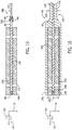
- FIG. 16 illustrates a portion of the probe 80 having the thermographic sensor assembly 288 inserted into a sleeve 296 that circumferentially 104 surrounds the sheath member 108 and the light pipe 84 along the longitudinal axis 100.
- the sleeve 296 may be manufactured from refractory materials (e.g., ceramics) suitable for high temperature environments.
Landscapes
- Physics & Mathematics (AREA)
- General Physics & Mathematics (AREA)
- Chemical & Material Sciences (AREA)
- Engineering & Computer Science (AREA)
- Combustion & Propulsion (AREA)
- Measuring Temperature Or Quantity Of Heat (AREA)
- Radiation Pyrometers (AREA)
Description
- The subject matter disclosed herein relates to, to thermographic temperature sensors, in particular to a thermographic temperature probe for use in high temperature environments.
- Gas turbine systems typically include at least one gas turbine engine having a compressor, a combustor, and a turbine. The combustor is configured to combust a mixture of fuel and compressed air to generate hot combustion gases, which, in turn, drive blades of the turbine. A temperature of exhaust gas produced by the gas turbine engine may vary depending on a configuration of the gas turbine engine, the fuel, and/or fuel-to-air ratios, among other combustion parameters. In certain applications, the temperature of the exhaust gas may be estimated, or may be measured using thermocouples. The temperature of the exhaust gas may be at temperature ranges that may be difficult to measure using existing temperature measurement techniques (e.g., applications). Therefore, it may be desirable to improve existing temperature measurement techniques for determining exhaust gas temperatures.
-
US 2014/269817 A1 discloses a high precision phosphor temperature sensor. The sensor includes a light source that emits an excitation light through a first optical fiber to a Y-coupler or splitter that connects the first optical fiber to a second optical fiber and a third optical fiber. The second optical fiber connects the Y-coupler to a detector and the third optical fiber connects the Y-coupler to a sensing end of the third optical fiber that is coated with a phosphor that produces a fluorescent emission when engaged by excitation light generated by the light source. The third optical fiber then transmits fluorescent emissions from the phosphor through the Y-coupler whereby at least some of the fluorescent emission passes through the second optical fiber to the detector. The lifetime of the fluorescent emission can be measured and the temperature at the phosphor can be calculated from said lifetime. -
US 2015/113942 A1 discloses a phosphor thermometer that comprises a light source configured to emit an excitation light, and an input waveguide configured to transmit at least a portion of the excitation light from the light source to a temperature sensing end. A phosphor is located at the temperature sensing end and it is configured to emit a fluorescence signal upon absorption of at least a portion of the excitation light transmitted by the input waveguide. The phosphor thermometer further comprises an output waveguide configured to transmit at least a portion of the fluorescence signal from the phosphor to a detector. The detector determines a fluorescence decay constant from the time dependent decay of the fluorescence signal, and the fluorescence decay constant is correlated with a temperature. - Certain embodiments commensurate in scope with the originally claimed invention are summarized below. These embodiments are not intended to limit the scope of the claimed invention, but rather these embodiments are intended only to provide a brief summary of possible forms of the invention. Indeed, the invention may encompass a variety of forms that may be similar to or different from the embodiments set forth below.
- According to the invention as herein claimed, a system includes a thermographic temperature sensor that is configured to measure a temperature of a fluid. The thermographic temperature sensor includes a probe having a housing and, as a sensing element, a light pipe that includes a thermographic phosphor. The system further comprises a waveguide, an optical source and a detector, wherein the optical source and the detector are coupled to the probe by the waveguide. The thermographic phosphor is configured to phosphoresce in response to absorbing light from the optical source. The phosphorescence by the thermographic phosphor is representative of a temperature of the fluid within a flow path of the fluid, and the detector that is configured to detect the phosphorescence by the thermographic phosphor. The housing of the probe includes a sheath member and a transition member; and the light pipe of the probe is disposed within the sheath member and the waveguide is disposed within the transition member, the sheath member and the transition member circumferentially surrounding the light pipe and the waveguide, the transition member comprising a central passage, receiving an end of the light pipe and an end of the waveguide, creating an air gap between the light pipe and the waveguide.
- In a second aspect of the invention as herein claimed, a method of measuring a temperature of a fluid includes directing light from an optical source by a waveguide to a probe that may contact the fluid and having a housing and a sensing element disposed within the housing, the light pipe including a thermographic phosphor, and the housing including a sheath member and transition member. The light pipe of the probe is disposed within the sheath member and the waveguide is disposed within the transition member. The sheath member and the transition member circumferentially surround the light pipe and the waveguide. The transmission member comprises a central passage, receiving an end of the light pipe and an end of the waveguide, creating an air gap between the light pipe and the waveguide. Phosphorescence from a thermographic phosphor of the sensing element is generated in response to absorbing the light of the optical source, directing the phosphorescence from the sensing element to a detector coupled to the probe by the waveguide, and the temperature of the fluid is determined based on a change in intensity of the phosphorescence over time.
- These and other features, aspects, and advantages of the present invention will become better understood when the following detailed description is read with reference to the accompanying drawings in which like characters represent like parts throughout the drawings, wherein:
-
FIG. 1 is a block diagram of a gas turbine system including a thermographic temperature sensor that measures a temperature of an exhaust gas generated in the gas turbine system; -
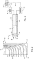
FIG. 2 is a schematic diagram of a temperature sensor manifold having a plurality of channels sized to receive one or more of the thermographic temperature sensors and to position the one or more thermographic temperature sensors along an exhaust gas flow path of the gas turbine system ofFIG. 1 ; -
FIG. 3 is a schematic diagram of the thermographic temperature sensor ofFIG. 1 having a thermographic temperature probe having a housing that encloses a sensing element coupled to an optical source and a detector; -
FIG. 4 is a perspective view of the thermographic temperature probe ofFIG. 3 having a housing including a sheath member and a transition member; -
FIG. 5 is a cross-sectional view of the thermographic temperature probe ofFIG. 4 including a sensing element having a thermographic phosphor enclosed within the housing of the thermographic temperature probe such that an annulus is formed between the housing and the sensing element; -
FIG. 6 is a diagram of a sensor sheath that forms part of the housing of the thermographic temperature probe ofFIG. 4 , the sensor sheath having a plurality of holes spaced apart along its longitudinal axis; -
FIG. 7 is a perspective view of a portion of the sensing sheath ofFIG. 6 having the plurality of holes spaced apart along its circumferential direction; -
FIG. 8 is a diagram of the sensing element ofFIG. 5 sized to fit within the housing of the thermographic temperature probe and having a thermographic phosphor disposed at an end of the sensing element; -
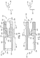
FIG. 9 is a cross-sectional view of a transition member that forms part of the housing of the thermographic temperature probe ofFIG. 4 , the transition member having a central passage with a variable inner diameter and a threaded inner surface at one end; -
FIG. 10 is a cross-sectional view of a transition member that forms part of the housing of the thermographic temperature probe ofFIG. 4 , the transition member having a central passage with a variable inner diameter and a threaded inner surface at first and second ends of the transition member; -
FIG. 11 is a process-flow diagram of a method for manufacturing a thermographic temperature probe having a sensing element disposed within a housing and having air cladding about a portion of a circumferential axis of the sensing element; -
FIG. 12 is a cross-sectional view of a sheath member having a plurality of channels spaced apart along a longitudinal axis and a circumferential direction of the sheath member and a central bore resulting from one or more steps of the method ofFIG. 11 ; -
FIG. 13 is a cross-sectional view of a sensor assembly having the sheath member of -
FIG. 12 and a thermographic light pipe secured to the sheath member via a plurality of radial supports resulting from one or more steps of the method ofFIG. 11 ; -
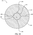
FIG. 14 is a cross-sectional view of a sensor assembly having a clamshell sheath member and a thermographic light pipe secured to the clamshell sheath member; -
FIG. 15 is a cross-sectional view of the sensor assembly ofFIG. 13 having fiber optic cabling attached to an end face of the thermographic light pipe resulting from one or more steps of the method ofFIG. 11 ; and -
FIG. 16 is a cross-sectional view of a thermographic temperature probe having the sensor assembly ofFIG. 15 disposed within a sleeve, as provided via one or more steps of the method ofFIG. 11 . - One or more specific embodiments of the present invention will be described below. In an effort to provide a concise description of these embodiments, all features of an actual implementation may not be described in the specification. It should be appreciated that in the development of any such actual implementation, as in any engineering or design project, numerous implementation-specific decisions must be made to achieve the developers' specific goals, such as compliance with system-related and business-related constraints, which may vary from one implementation to another. Moreover, it should be appreciated that such a development effort might be complex and time consuming, but would nevertheless be a routine undertaking of design, fabrication, and manufacture for those of ordinary skill having the benefit of this disclosure.
- When introducing elements of various embodiments of the present invention, the articles "a," "an," "the," and "said" are intended to mean that there are one or more of the elements. The terms "comprising," "including," and "having" are intended to be inclusive and mean that there may be additional elements other than the listed elements.
- Present embodiments are generally directed toward system and methods for measuring fluid temperatures (e.g., exhaust gas temperature). For example, in gas turbine systems, one or more gas turbine engines may combust a fuel/oxidant mixture to produce combustion gases (e.g., exhaust gases) for driving one or more turbine stages, each having a plurality of blades. Depending on a number of factors, such as the type of fuel that is combusted as well as various combustion parameters (e.g., fuel and/or air flow, pressure, etc.) and gas turbine engine configurations, a temperature of the exhaust gas resulting from the combustion process may vary. Evaluating a temperature of the exhaust gas generated by various gas turbine engine configurations and operating (e.g., combustion) parameters may facilitate design of system components downstream of a combustor of the gas turbine engine. Additionally, in existing gas turbine engines, it may be desirable to monitor the exhaust gas temperatures to monitor combustion parameters of the gas turbine system.
- It is now recognized that direct measurement of the temperature of the exhaust gas produced in the gas turbine engine during combustion, also allows for a more direct evaluation of operational parameters of the gas turbine system when adjusted. In addition, other operating parameters may be adjusted in response to these direct temperature measurements. For example, an amount of cooling fluid (e.g., air) used to cool system components downstream of the gas turbine engine may be adjusted and/or redirected to other system components based on such temperature measurements. Also, certain gas turbine engine models may generate an exhaust gas having a temperature that may not require a substantial amount of cooling fluid to cool the exhaust gas and/or downstream system components (e.g., system components downstream of a combustor of the gas turbine engine) in contact with the exhaust gas. Therefore, an amount of air generally used to cool the exhaust gas and/or downstream system components downstream of the combustor may be decreased compared to gas turbine engines that generate exhaust gases having temperatures above a desired threshold. Accordingly, at least a portion of the air used to cool the exhaust gas and/or system components downstream of the combustor may be redirected to the combustor of the gas turbine engine or other system processes that may utilized the air. Moreover, knowing the temperature of the exhaust gas exiting the gas turbine engine may facilitate selection of materials used to fabricate the system components downstream of the gas turbine engine.
- In some configurations, exhaust gas temperatures may be evaluated in a combustion testing laboratory using a combustion testing apparatus that is representative of an engine configuration associated with a particular gas turbine engine model. The combustion testing apparatus may simulate performance of the gas turbine engine model that may be incorporated into a particular gas turbine system. One way of measuring exhaust gas temperatures in the combustion testing apparatus is with a thermocouple. For example, Type B thermocouples may be used with the combustion testing apparatus to directly measure the temperature of the exhaust gas exiting a combustor of the combustion testing apparatus. Thermocouples, such as Type B thermocouples, are manufactured from metallic materials such as a mixture of platinum (Pt) and rhodium (Rh). Type B thermocouples are suitable for measuring fluid temperatures up to approximately 1700 °C, which is the highest temperature limit for thermocouples. However, certain large frame heavy duty gas turbine engines having a megawatt range greater than 50 megawatts (MW) (e.g., non-Areo derivative gas turbine engines) may generate exhaust gas having temperatures in excess of 1700 °C. As such, during combustion testing of large frame heavy duty gas turbine engines, the thermocouples used to measure the exhaust gas temperature in the combustion testing apparatus are generally replaced after a single use, thereby increasing the overall cost of combustion testing. The measurements using these thermocouples may also be inaccurate at such temperatures. In accordance with present embodiments, it is now recognized that temperature sensors that use thermographic materials (e.g., rare-earth-or transition metal-doped ceramic phosphors, also known as thermographic phosphors) may be used to replace thermocouples for high temperature measurement applications. The thermographic temperature sensors may include non-metallic refractory materials (e.g., ceramics) that may be more appropriate for use in temperature sensing applications that are unsuitable for thermocouples.
- Thermographic phosphors may have a temperature threshold that is above 1700 °C. Therefore, using thermographic temperature sensors for measuring exhaust gas temperatures in the combustion testing apparatus or any other high temperature environment may mitigate the undesirable costs associated with replacement of thermocouples used to measure high temperature fluids (e.g., exhaust gas) after each use. Additionally, the thermographic temperature sensors may provide a more accurate temperature measurement compared to traditional thermocouples at temperatures above 1700 °C. Generally, thermographic phosphors are coated onto surfaces of interest to indirectly measure a temperature of a fluid (e.g., exhaust gas) based on the temperature of the surface that is in contact with the fluid. However, depending on the thermal properties (e.g., thermal conductivity) of the surface, the temperature of the surface may not be representative of the fluid that is in contact with the surface. Therefore, it may be desirable to fabricate a thermographic temperature sensor that may be immersed within a fluid of interest to directly measure the temperature of the fluid of interest (e.g., exhaust gas). Accordingly, present embodiments include a thermographic temperature probe that are used to directly measure the temperature of fluids of interest, even when the temperature of the fluid is greater than the suitable temperature range for traditional thermocouples.
- With the foregoing in mind,
FIG. 1 is a schematic diagram of an examplegas turbine system 10 that includes agas turbine engine 12 having acombustor 14 and aturbine 16. In certain arrangements, thegas turbine system 10 may be all or part of a power generation system. In other arrangements, thegas turbine system 10 may be part of a laboratory combustion testing apparatus. Thegas turbine system 10 also includes one or morethermographic temperature sensors 20 positioned along aflow path 22 of anexhaust gas 24 generated in thecombustor 14. For example, in the illustrated arrangement, the one or morethermographic temperature sensors 20 are located between the combustor 14 and theturbine 16. However, in other arrangements, the one or morethermographic temperature sensors 20 may be located downstream of theturbine 16 or at any other suitable location within thegas turbine system 10. - In operation, the
gas turbine system 10 may use liquid or gas fuel, such as natural gas and/or a hydrogen-rich synthetic gas, to run thegas turbine system 10. As shown inFIG. 1 ,fuel 28 and air 30 (e.g., compressed air) enter thecombustor 14. For example, one or more fuel nozzles may inject a fuel-air mixture into thecombustor 14 in a suitable ratio for desired combustion, emissions, fuel consumption, power output, and so forth. The combustion of thefuel 28 and theair 30 may generate the hot pressurized exhaust gas 24 (e.g., combustion gases), which may then be utilized to drive one or more turbine blades within theturbine 16. For example, in operation, the combustion gases (e.g., the exhaust gas 24) flowing into and through theturbine 16 may flow against and between the turbine blades, thereby driving the turbine blades and, thus, a shaft of thegas turbine engine 12 into rotation to drive a load, such as an electrical generator in a power plant. In arrangements where thesystem 10 is a testing apparatus, theturbine 16 may not necessarily be in place. - The one or more
thermographic temperature sensors 20 may be used to measure the temperature of theexhaust gas 24 within thegas turbine system 10. For example, the one or morethermographic temperature sensors 20 may measure the temperature of theexhaust gas 24 within or immediately downstream of thecombustor 14, upstream of the turbine 16 (e.g., between the combustor 14 and the turbine 16), downstream of the turbine 16 (e.g., in an exhaust duct), or any other suitable location within thegas turbine system 10. Depending on the configuration of thegas turbine engine 12 and/or the fuel used in thegas turbine system 10, the temperature of theexhaust gas 24 may be above a temperature (e.g., 1700 °C) suitable for using existing thermocouples. For example, certain large frame heavy duty gas turbine engines may generate exhaust gases having temperatures above 1700 °C (e.g., between approximately X and Y °C). As discussed above, thermocouples are generally used to measure the temperature of the exhaust gas generated in combustion systems (e.g., thegas turbine system 10, combustion testing apparatus, etc.). However, Type B thermocouples, which have the highest temperature tolerance compared to other types of thermocouples, are not suitable for measuring temperatures of fluids (e.g., the exhaust gas 24) that are above 1700 °C. Additionally, the metallic materials used to manufacture thermocouples may not be sufficiently durable to withstand fluid temperatures exceeding 1700 °C. Thermographic phosphor-based temperature sensors of the present disclosure may be manufactured from non-metallic refractory materials that may be more durable and/or resistant to fluid temperatures above 1700 °C compared to the metal-based thermocouple temperature sensors. - The present disclosure uses a thermographic phosphor disposed within a temperature probe that may be inserted into a flow path of the fluid of interest. In this way, the thermographic phosphor may be used to directly measure the temperature of the fluid of interest rather than the temperature of the surface that may be exposed to the fluid. Accordingly, the one or more
thermographic temperature sensors 20 may include a temperature probe having thermographic phosphors such as rare-earth- or transition metal-doped crystals that may be used to directly measure the temperature of theexhaust gas 24. As discussed in further detail below with reference toFIG. 3 , the thermographic phosphors may be excited with optical energy, resulting in phosphorescence of the thermographic phosphors. Certain characteristics of the phosphorescence may be a function of the temperature of the fluid. Thus, in accordance with certain arrangements, the phosphorescence of the thermographic phosphors may be measured over time to determine the temperature of theexhaust gas 24. - The illustrated
gas turbine system 10 also includes acontrol system 34 configured to control operation of thegas turbine system 10 and/or determine the temperature of theexhaust gas 24 based on the temperature measurements obtained from the one ormore temperature sensors 20. Thecontrol system 34 may independently control operation of thegas turbine system 10 by electrically communicating with sensors, control valves, and pumps, or other flow adjusting features throughout thegas turbine system 10. Thecontrol system 34 may include a distributed control system (DCS) or any computer-based workstation that is fully or partially automated. For example, thecontrol system 34 can be any device employing a general purpose computer or an application-specific device, both of which may generally includememory circuitry 36 storing one or more instructions for controlling operation of thegas turbine system 10, determining combustion parameters, and determining a temperature of theexhaust gas 24, among others. Thememory 36 may store algorithms used to determine the temperature of theexhaust gas 24 based on phosphorescence characteristics of the thermographic phosphor in the one ormore temperature sensors 20. The processor may include one or more processing devices (e.g., microprocessor 38), and thememory circuitry 36 may include one or more tangible, non-transitory, machine-readable media collectively storing instructions executable by the processor to control actions described herein. - In certain arrangements, the
control system 34 may include separate controllers for controlling thegas turbine engine 12 and thetemperature sensor 20. In one arrangement, thetemperature sensor 20 includes its own controller. For example, a temperature controller may be disposed within a housing of thetemperature sensor 20. The temperature controller may communicate with thecontrol system 34 to control operational parameters of thegas turbine system 10 based on the temperature of theexhaust gas 24. - Additionally or alternatively, the
control system 34 of thegas turbine system 10 may perform functions such as notifying the operators of thesystem 10 to adjust operating parameters, perform service, or otherwise cease operating thesystem 10. In some arrangements, thecontrol system 34 may also implement corrective actions specifically relating to adjusting fuel/air ratios, exhaust temperature, flow rates of cooling air, or any other suitable parameter of thegas turbine system 10. - In certain arrangements, the
control system 34 may use information provided via one or more input signals 40 from one or more sensors (e.g., the temperature sensor 20) of thegas turbine system 10 to execute instructions or code contained on thememory 36 and generate one or more output signals 42 to various flow control devices to control a flow of fluids (e.g., thefuel 28 and the air 30) within thegas turbine system 10. In one arrangement, thecontrol system 34 may control operation of optical components of the one ormore temperature sensors 20 to determine the temperature of theexhaust gas 24, as discussed in further detail below with reference toFIG. 3 . - The one or more
thermographic temperature sensors 20 may measure the temperature of theexhaust gas 24 in thegas turbine system 10 within or downstream of the combustor 14 (e.g., along a flow path of theexhaust gas 24 between the combustor 14 and the turbine 16). In certain arrangements, thegas turbine system 10 may include a manifold that may facilitate placement of the one ormore temperature sensors 20 along (within) the flow path of theexhaust gas 24. For example,FIG. 2 illustrates a temperature manifold 50 (e.g., a temperature rake) that may be used in thegas turbine system 10 to facilitate direct measurement of the temperature of theexhaust gas 24 with the one or morethermographic sensors 20. Thetemperature manifold 50 includes abody 52 having a plurality ofchannels 54 sized to accommodate the one ormore temperature sensors 20. Each channel of the plurality ofchannels 54 extends from amanifold end 56 toward amanifold sidewall 58, and terminates in anopening 62 on themanifold sidewall 58. Theopenings 62 may be disposed at progressively increasing distances away from themanifold end 56. In use, each sensor of the one or morethermographic temperature sensors 20 may be inserted into aport 70 of the respective channel of the plurality ofchannels 54 disposed adjacent to themanifold end 56. The channel of the plurality ofchannels 54 may guide the one or morethermographic temperature sensors 20 through thetemperature manifold 50 and through theopening 62. Atip 72 of the one ormore temperature sensors 20 may extend a distance away from thesidewall 58 and into the flow path of the exhaust gas 24 (e.g., an exhaust flow path upstream of the turbine 16). In this way, the one ormore temperature sensors 20 may directly measure the temperature of theexhaust gas 24 in thegas turbine system 10. -
FIG. 3 illustrates an arrangement of the one ormore temperature sensors 20 that may be used to measure the temperature of theexhaust gas 24 in thegas turbine system 10. Again, thetemperature sensor 20 may be suitable for measuring temperatures of a wide variety of fluids especially those expected to have a temperature above ranges that are generally appropriate for traditional thermocouples. In the illustrated arrangement, thetemperature sensor 20 includes aprobe 80 having ahousing 82 that encloses alight pipe 84 and certain other components of the one or more temperature sensors 20 (e.g., waveguide). Thelight pipe 84 includes a base material (e.g., non-doped yttrium aluminum garnet (YAG) crystal, sapphire crystal, quartz crystal, zirconia fibers) and a thermographic phosphor 86 (e.g., a sensing element) that may emit a certain intensity of light depending on the temperature of theexhaust gas 24 or other fluid of interest. For example, the one or morethermographic temperature sensors 20 may include an optical source 90 (e.g., an ultraviolet (UV) lamp, laser, light emitting diode (LED)) that, when activated, emits light 92 toward thelight pipe 84. In response to the emittedlight 92, thethermographic phosphor 86 in thelight pipe 84 luminesces and emits light 94. Adetector 96 receives the emitted light 94 from thethermographic phosphor 86 and transmits an output signal of the one or more output signals 40 to thecontrol system 34. In certain arrangements, theprobe 80 includes a controller separate from thecontrol system 34 that processes the signal from the emitted light 94 to determine a temperature of theexhaust gas 24, and outputs the temperature of theexhaust gas 24 to thecontrol system 34. For example, the controller may be disposed within a housing of theprobe 80. Thecontrol system 34 may control operational parameters of thegas turbine system 10 based on the temperature of theexhaust gas 24. Additionally, theoptical source 90 and thedetector 96 may be disposed within the housing of theprobe 80 such that theprobe 80 may be portable. - The
control system 34 may send an input signal of the one or more input signals 42 to theoptical source 90, thereby activating theoptical source 90 to emit the light 92 for a desired period of time (e.g., between approximately 1 nanosecond (ns) and 10 ns). Once thedetector 96 detects the light 94 emitted by thethermographic phosphor 86, thedetector 96 may send the output signal of the one or more output signals 40 to thecontrol system 34 indicating that thethermographic phosphor 86 absorbed the light 92 emitted by theoptical source 90 and is emitting the light 94 in response to the light 92 from theoptical source 90. Following detection of the light 94, thecontrol system 34 may send another input signal of the one or more input signals 42 to theoptical source 90 to deactivate theoptical source 90. Thethermographic phosphor 86 continues to phosphoresce (e.g., emit the light 94) for a period of time after deactivation of theoptical source 90. A characteristic of the phosphorescence of thethermographic phosphor 86 as a function of time may be used to determine the temperature of a fluid (e.g., the exhaust gas 24). For example, the intensity of the light 94 emitted by thethermographic phosphor 86 steadily decreases over time (e.g., decays). The decay (or lifetime) of phosphorescence of thethermographic phosphor 86 is a function of the temperature of the exhaust gas 24 (or any other fluid of interest). Accordingly, thecontrol system 34 may determine the decay of phosphorescence (e.g., a decrease in the intensity of the light 94 over time) of thethermographic phosphor 86 to determine the temperature of theexhaust gas 24. In certain arrangements, thethermographic phosphor 86 may emit multiple wavelengths. Therefore, a ratio between two wavelengths of interest may be used to determine the temperature of theexhaust gas 24. - As discussed above, the
thermographic phosphor 86 is enclosed within thehousing 82 of theprobe 80 associated with the one or morethermographic temperature sensors 20. Theprobe 80 may be positioned along the flow path of the exhaust gas 24 (or any other fluid of interest) such that thethermographic phosphor 86 in thelight pipe 84 may directly measure the temperature of theexhaust gas 24.FIG. 4 illustrates an arrangement of theprobe 80 of the one or morethermographic temperature sensors 20 that may be used to measure the temperature of a fluid of interest, such as theexhaust gas 24 generated in thegas turbine system 10. Theprobe 80 may have an axial axis ordirection 100, a radial axis ordirection 102 away fromaxis 100, and a circumferential axis ordirection 104 aroundaxis 100. In the illustrated arrangement, thehousing 82 of theprobe 80 includes asheath member 108 and atransition member 110. Thesheath member 108 forms part of anexterior surface 114 of theprobe 80, and includes a plurality ofholes 116 along the axial andcircumferential directions sheath member 108, as discussed below with reference toFIG. 16 . - The
probe 80 disclosed herein is suitable for use in high-temperature environments (e.g., environments having temperatures above 1700 °C). For example, theprobe 80 may be used to measure temperatures between approximately 1500 °C and approximately 2500 °C. However, theprobe 80 may also measure temperatures below 1500 °C, similar to thermocouples. As an example, some or all of the components of theprobe 80 may be manufactured from non-metallic materials that are durable at temperatures up to approximately 2500 °C. For example, thesheath member 108, thetransition member 110, or both, may be manufactured from refractory materials (e.g., ceramic) including, but not limited to, oxides (e.g., aluminum oxide, calcium oxide), silica, magnesia, carbides (e.g., silicon carbide, tungsten carbide), zirconia, graphite, boron nitride, corrosion-resistant metal alloy (e.g., HASTELLOY®) or any other suitable high temperature material. In certain arrangements, thetransition member 110 is manufactured from materials having a low coefficient of thermal expansion (e.g., between approximately 3 and 6). For example, thetransition member 110 may be manufactured from materials such as, but not limited to, tungsten or vanadium. - The
sheath member 108 encloses (e.g., circumferentially surrounds) one or more components of theprobe 80. For example, thesheath member 108 may encapsulate thelight pipe 84 and at least a portion of the waveguide (e.g., fiber optic cabling) used to facilitate transmission of signals (e.g., the light 92, 94) to and from thelight pipe 84. Thetransition member 110 is positioned between thesheath member 108 andtubing 120 that houses the fiber optic cabling. Thetubing 120 extends axially away from aproximal surface 124 of thetransition member 110 that is opposite thetip 72 of theprobe 80. A proximal end of the tubing 120 (e.g., a tube end furthest away from the transition member 110) may terminate in a connector configured to couple theprobe 80 to theoptical source 90 and thedetector 96. As discussed in further detail below, thetransition member 110 may facilitate alignment of the fiber optic cabling and thelight pipe 84 such that the fiber optic cabling may direct and receive the light 92, 94, respectively, to and from thelight pipe 84. Additionally, in certain arrangements, thetransition member 110 may create an air gap between thelight pipe 84 and the fiber optic cabling, which may facilitate distribution of the light 92 before the light 92 impinges on thelight pipe 84, as discussed in further detail below. The fiber optic cabling may be a single fiber that receives and transmits the light 92, 94 through theprobe 80. However, in one arrangement, the fiber optic cabling may include dedicated fiber optic cable for receiving and transmitting the light 92 from theoptical source 90 to thelight pipe 84 and a dedicated fiber optic cable for receiving and transmitting the light 94 from thethermographic phosphor 86 to thedetector 96. -
FIG. 5 illustrates a cross-sectional view of aprobe 80. As discussed above, thesheath member 108 and thetransition member 110 circumferentially surround thelight pipe 84 and a waveguide (e.g., fiber optic cabling 128), respectively. Thefiber optic cabling 128 transmits the light 92 emitted by theoptical source 90 to thethermographic phosphor 86 in thelight pipe 84. Additionally, as discussed above, thefiber optic cabling 128 receives the light 94 emitted by thethermographic phosphor 86 and transmits the light 94 to thedetector 96. Accordingly, it may be desirable to surround thelight pipe 84 with air (e.g., air cladding, air gap) to efficiently transmit light to thethermographic phosphor 86. The air around thelight pipe 84 may facilitate guiding the light 92, 94 through thelight pipe 84, thereby improving signal strength. - In the illustrated arrangement, the
light pipe 84 has anouter diameter 127 that is smaller than a firstinner diameter 129 of thesheath member 108. For example, theouter diameter 127 may be between approximately 5% and approximately 80% less than theinner diameter 129 of thesheath member 108. As such, anouter wall 130 of thelight pipe 84 may be positioned radially 102 away from aninner wall 132 of thesheath member 108 by adistance 134, thereby forming afirst annulus 138 between theouter wall 130 of thelight pipe 84 and theinner wall 132 of thesheath member 108. Thefirst annulus 138 may be filled with air or any other suitable gas to facilitate guiding transmission of the light 92, 94 through thelight pipe 84. - A portion of the
sheath member 108 may be disposed within thetransition member 110 such that asheath end face 140 abuts a firstinner surface 142 of thetransition member 110. Thetransition member 110 may facilitate alignment of anend face 146 of thelight pipe 84 and afiber end face 148 of thefiber optic cabling 128 to allow transmission of the light 92, 94 between thelight pipe 84 and thefiber optic cabling 128. - In certain arrangements, the
end face 146 of thelight pipe 84 and the fiberoptic end face 148 may be in contact with one another. In other arrangements, anair gap 150 may separate theend face 146 and the fiberoptic end face 148. Theair gap 150 may facilitate uniform distribution of the light 92, 94 over a surface area of thetransition member 110 before the light 92, 94 impinges onto therespective end face end face thermographic phosphor 86 in thelight pipe 84 may include materials such an yttrium aluminum garnet (YAG) crystal, lutetium aluminum garnet (LuAG) crystal, scandium aluminum garnet (ScAG) crystal, yttrium aluminum boron nitrogen garnet (YABNG) crystal, yttrium aluminium boron garnet (YABG) crystal, quartz crystal, sapphire crystal, or any other suitable crystal doped with a thermographic phosphor. By way of example, the crystal may be doped with rare earth elements such as neodymium (Nd), chromium (Cr), erbium (Er), ytterbium (Yb), cerium (Ce), dysprosium (Dy), thulium (Tm), or any other suitable thermographic phosphor and combinations thereof. - Each thermographic phosphor may require a certain light energy for luminescence that is different from another materially different thermographic phosphor. Similarly, each thermographic phosphor may output light energy that is different from the light energy of another materially different thermographic phosphor. In certain arrangements, the amount of energy emitted by the
optical source 90 and/or thethermographic phosphor 86 may be high-energy light (e.g., short wavelength light). The intensity of the high-energy light may damage theend face light pipe 84 and thefiber optic cabling 128, respectively. Theair gap 150 may uniformly distribute energy from the light 92, 94 over a surface area of thetransition member 110, which may decrease the intensity at which the light 92, 94 impinges on theend face light pipe 84 that may result from the energy associated with the light 92, 94 may be reduced compared to probe configurations that do not include theair gap 150. Additionally, theair gap 150 may allow the end faces 146, 148 of thelight pipe 84 and thefiber optic cabling 128, respectively, to include angles, bevels, and/or optical lenses, which may mitigate reflection of the light 92, 94 between thelight pipe 84 and thefiber optic cabling 128. - A portion of the
fiber optic cabling 128 is enclosed within thetubing 120, which facilitates coupling theprobe 80 to theoptical source 90 and thedetector 96. Additionally, thetubing 120 may be used to carry cooling air through thetemperature sensor 20 to maintain thefiber optic cabling 128 at a temperature that meets the constraints of the mechanical properties of thefiber optic cabling 128. In the illustrated arrangement, thetubing 120 is inserted into aproximal end 154 of thetransition member 110 and through at least a portion of acentral passage 158 of thetransition member 110. In certain arrangements, thetubing 120 may be threaded into thetransition member 110. Threading thetubing 120 may facilitate decoupling thetubing 120 from thetransition member 110, for example, during maintenance and/or repair of theprobe 80. In other arrangements, thetransition member 110 may be inserted into thetubing 120 such that thetubing 120 circumferentially 104 surrounds at least a portion of theproximal end 154 of thetransition member 110. An adhesive may be used to adhere thetubing 120 to thetransition member 110 to reinforce the coupling between thetubing 120 and thetransition member 110. In certain arrangements, brazing and crimping could be used to couple thetubing 120 to thetransition member 110. - As discussed above, the
light pipe 84 is disposed within thesheath member 108 such that an air cladding (e.g., air gap) formed within thefirst annulus 138 of thesheath member 108 circumferentially 104 surrounds thelight pipe 84. That is, the firstouter wall 130 of thelight pipe 84 is not in contact with theinner wall 132 of thesheath member 108. Accordingly, theprobe 80 may include features that facilitate positioning and securing thelight pipe 84 within thefirst annulus 138 such that at least a portion of the light pipe 84 (e.g., greater than approximately 90% of a total surface area of the light pipe 84) may be circumferentially 104 surrounded by air (e.g., air cladding). For example, theprobe 80 may includeradial supports 164 positioned at various locations along thelongitudinal axis 100 of theprobe 80 and extending radially 102 between thelight pipe 84 and thesheath member 108. The location of the radial supports 164 may correspond to a position of the plurality ofholes 116 on thesheath member 108. In certain arrangements, an adhesive (e.g., ceramic adhesive) may be injected into each hole of the plurality ofholes 116 of thesheath member 108. Once cured, the adhesive binds to theouter wall 130 of thelight pipe 84 and sheath sidewalls 168 of thesheath member 108, thereby forming the radial supports 164 and securing thelight pipe 84 within thesheath member 108. - A
first dimension 170 of the radial supports 164 may be controlled by asecond dimension 172 of the plurality ofholes 116. That is, thefirst dimension 170 of the radial supports 164 may be limited by thesecond dimension 172 of the respective hole of the plurality ofholes 116. In other arrangements, an injection pressure of the adhesive may be used to control thefirst dimension 170 of the radial supports 164. - In certain arrangements, the radial supports 164 may include inserts (e.g., rods) manufactured from refractory materials and sized to fit within the plurality of
holes 116. The inserts may be inserted into the plurality ofholes 116 and adhered to theouter surface 130 of thelight pipe 84 and the sheath sidewalls 168 of thesheath member 108 with the adhesive. The rods may be cylindrical, rectangular, prismatic, T-shaped, or any suitable geometry. - It may be desirable to minimize contact between the radial supports 164 and the
light pipe 84. Therefore, each hole of the plurality ofholes 116 may be sized and spaced apart such that each of the radial supports 164 may contact between approximately 0.5 % and approximately 10% of a total surface area of theouter surface 130 of thelight pipe 84. For example,FIG. 6 illustrates an arrangement of thesheath member 108 having each hole of the plurality ofholes 116 spaced apart along both thelongitudinal axis 100 and thecircumferential axis 104 of thesheath member 108. In the illustrated arrangement, each hole of the plurality ofholes 116 is spaced apart a distance 180 (e.g., measured from center to center of each hole) along thelongitudinal axis 100 of thesheath member 108. Additionally, as illustrated inFIG. 7 , each hole of the plurality ofholes 116 is circumferentially 104 aligned and spaced apart from an adjacent hole of the plurality ofholes 116 by anangle 190. As such, the radial supports 164 (seeFIG. 5 ) may contact thelight pipe 84 at various points along both thelongitudinal axis 100 and thecircumferential axis 104 of thelight pipe 84 to reinforce and secure thelight pipe 84 within thesheath member 108. - Returning to
FIG. 6 , thesheath member 108 may have a firstlongitudinal dimension 184 and a firstouter dimension 186. While the firstlongitudinal dimension 184 of thesheath member 108 may be any suitable size, in certain arrangements, the firstlongitudinal dimension 184 of thesheath member 108 may be between approximately 5% and approximately 250% or more greater than a longitudinal dimension of the light pipe 84 (e.g., the secondlongitudinal length 210 shown inFIG. 8 ). - The first
outer dimension 186 of thesheath member 108 may be sized to fit into the one ormore channels 54 of the temperature manifold 50 (seeFIG. 2 ). For example, the firstouter dimension 186 may be between approximately 0.5% and approximately 5% less than an inner diameter of the one ormore channels 54. In certain arrangements, the firstouter dimension 186 may be between approximately 1 mm and approximately 5 mm. However, the firstouter dimension 186 may be any other suitable size. In one arrangement, the firstlongitudinal dimension 184 and the firstouter dimension 186 of thesheath member 108 are such thatprobe 80 has overall dimensions that may be approximately equal to dimensions of conventional thermocouple temperature sensors. As such, theprobe 80 may be used to replace thermocouple temperature sensors for fluid temperature measurement applications. Additionally, the air cladding on thelight pipe 84 may mitigate other processes that may cause noise or other delays (e.g., scattering). - As discussed above, the plurality of
holes 116 are spaced apart along thelongitudinal axis 100 of thesheath member 108. Therefore, in some arrangements, based on the firstlongitudinal dimension 184 of thesheath member 108, thedistance 180 between each hole of the plurality ofholes 116 along thelongitudinal axis 100 may be between approximately 5% and approximately 50% of the firstlongitudinal dimension 184. For example, in certain arrangements, thedistance 180 may be between approximately 6 millimeters (mm) and approximately 25 mm. As such, the radial supports 164 may contact between approximately 0.5 % and approximately 10% of the total surface area of theouter surface 130 of thelight pipe 84, and the air cladding on thelight pipe 84 may circumferentially 104 surround between approximately 90% and approximately 99% of thelight pipe 84. Consequently, the light 92, 94 may be transmitted through thelight pipe 84 more efficiently, and signal strength may be improved compared to sensing elements that do not include air cladding. - In the illustrated arrangement, a sheath
proximal end 192 may include a threadedouter surface 194 that may facilitate coupling thesheath member 108 to the transition member 110 (seeFIG. 5 ). The sheathproximal end 192 may be inserted into thecentral passage 158 of thetransition member 110 to secure thesheath member 108 to thetransition member 110 via a threaded connection. For example, the sheathproximal end 192 may have a secondouter diameter 196 that may be approximately equal to at least a portion of an inner diameter of thecentral passage 158 of the transition member 110 (to allow for an interference or friction fit connection). As such, the sheathproximal end 192 may be inserted into a portion of thecentral passage 158. The threadedouter surface 194 of thesheath member 108 may engage with complementary threads within thecentral passage 158 to secure thesheath member 108 to thetransition member 110. In certain arrangements, the secondouter diameter 196 may be less than the firstouter diameter 186 of thesheath member 108. Therefore, the outer surface of theprobe 80 may not have protruding surfaces along thelongitudinal axis 100 that may interfere with insertion of theprobe 80 into, for example, the respective channel of the plurality ofchannels 54 of thetemperature manifold 50. - In certain arrangements, a
proximal tip 198 of thesheath member 108 may be tapered. The taperedproximal tip 198 may facilitate insertion of the sheathproximal end 192 into thecentral passage 158 of thetransition member 110. The firstinner surface 142 of thecentral passage 158 may have a complementary tapered shape that accommodates the taperedproximal tip 198. This arrangement may facilitate alignment between theend face 146 of thelight pipe 84 and thefiber end face 148 of thefiber optic cabling 128. - As discussed above, the
sheath member 108 encapsulates thelight pipe 84 and the thermographic phosphor 86 (e.g., sensing element) used to measure the temperature of theexhaust gas 24 or any other suitable fluid. Accordingly, thelight pipe 84 is dimensioned to fit within thesheath member 108.FIG. 8 illustrates an arrangement of thelight pipe 84 that may be encapsulated within thesheath member 108. Thelight pipe 84 includes afirst end 200 having theend face 146 and asecond end 204 that is opposite thefirst end 200. Thelight pipe 84 includes afirst portion 206 and asecond portion 208 that form a secondlongitudinal length 210 of thelight pipe 84. Thefirst portion 206 of thelight pipe 84 extends from theend face 146 to aninterface point 209 between thefirst portion 206 and thesecond portion 208. In one arrangement, thesecond portion 208 may be between approximately 1% and approximately 50% of the secondlongitudinal length 210 of thelight pipe 84. However, thesecond portion 208 may be any other suitable dimension. - The
first portion 206 may be manufactured from non-doped crystals such as yttrium aluminum garnet (YAG) crystals, sapphire crystals, quartz crystals, or any other suitable crystal that may support thethermographic phosphor 86. Thesecond portion 208 may be positioned at thesecond end 204 and includes thethermographic phosphor 86. Thethermographic phosphor 86 includes doped crystals such as rare earth- or transition metal-doped YAG, rare earth- or transition metal-doped quartz, or rare earth-or transition metal-doped sapphire crystals. Accordingly, thefirst portion 206 is the base of thelight pipe 84 and thesecond portion 208 is the dopant. In one arrangement, thefirst portion 206 and thesecond portion 208 of thelight pipe 84 are monolithic. That is, the non-doped crystal and the doped crystal are bonded together during crystal growth to form a single integrated structure. In another arrangement, thefirst portion 206 and thesecond portion 208 are discrete (e.g., non-bonded, unattached) portions that are in contact with one another within thesheath member 108. For example, each respective end face of the first portion 206 (e.g., non-doped crystal) and the second portion 208 (e.g., doped crystal) are in contact with one another at theinterface point 209. However, in one arrangement, thefirst portion 206 and thesecond portion 208 are separated from one another such that theportions thermographic phosphor 86 is a powder that may be disposed on an end face (e.g., end face adjacent to the interface point 209) of thefirst portion 206. The thermographic phosphor powder may be mixed with binders or other suitable materials to consolidate powder particulates and facilitate deposition on the end face of thefirst portion 206. By way of example, the thermographic phosphor powder may be YABNG:Dy, YABG:Dy, or any other suitable thermographic phosphor. - As discussed above, the
light pipe 84 is housed within thesheath member 108. Therefore, the secondlongitudinal length 210 of thelight pipe 84 may be approximately equal to or less than the firstlongitudinal length 184 of thesheath member 108. For example, in one arrangement, the secondlongitudinal length 210 may be such that thefirst end 200 of thelight pipe 84 co-terminates (e.g., is flush) with theproximal end 192 of thesheath member 108. In another arrangement, thefirst end 200 of thelight pipe 84 is below theproximal end 192 of thesheath member 108. However, in other arrangements, the secondlongitudinal length 210 is greater than the firstlongitudinal length 184 such that thefirst end 200 of the light pipe extends beyond theproximal end 192 of thesheath member 108. In this particular arrangement, thefirst end 200 of thelight pipe 84 may be inserted into thecentral passage 158 of thetransition member 110. -
FIG. 9 is a cross-sectional view of atransition member 110 that may be used with theprobe 80. As discussed above, thecentral passage 158 of thetransition member 110 may receive an end of the sheath member 108 (e.g., the proximal end 192) and thetubing 120 to align theend face 146 of thelight pipe 84 and the fiberoptic end face 148. Thecentral passage 158 includes afirst section 216, asecond section 218, and athird section 220. Thefirst section 216 of thecentral passage 158 longitudinally 100 extends away from theproximal end 154 of thetransition member 110 to thesecond section 218. Thesecond section 218 longitudinally 100 extends away from thefirst section 216 to thethird section 220. That is, thesecond section 218 is positioned between the first and thethird sections third section 220 longitudinally 100 extends away from thesecond section 218 to a transitiondistal end 226 of thetransition member 110. - The
central passage 158 may have a variable diameter to accommodate various components of theprobe 80. For example, thefirst section 216 has afirst diameter 230 sized to receive thetubing 120, thesecond section 218 has asecond diameter 232 sized to receive thefiber optic cabling 128, and thethird section 220 has athird diameter 236 sized to receive theproximal end 192 of the sheath member 108 (seeFIG. 7 ). In certain arrangements, thecentral passage 158 may be two separate passages sized to receive a dedicated fiber optic cable for sending the light 92 to thelight pipe 84 or a dedicated fiber optic cable for receiving the light 94 emitted by thethermographic phosphor 86. In the illustrated arrangement, thefirst section 216 includes a threadedinner surface 238 that engages with a complementary threaded outer surface of thetubing 120 to secure thetubing 120 to thetransition member 110. The threaded connection between thetransition member 110 and thetubing 120 may facilitate a secure connection while also allowing decoupling of thetubing 120 from thetransition member 110 to replace sensor components (e.g., thetubing 120 and/or the fiber optic cabling 124). However, in other arrangements, thefirst section 216 may not include the threadedinner surface 238. Rather, the inner surface of thefirst section 216 may be smooth. In this particular arrangement, thetubing 120 may be secured within thefirst section 216 of thetransition member 110 via an interference fit (e.g., via ribs on the outer surface of the tubing 120) and/or with an adhesive. - In certain arrangements, at least a portion of the
first diameter 230 of thefirst section 216 may gradually decrease. For example, in the illustrated arrangement, thefirst diameter 230 decreases toward thesecond section 218 such that thefirst section 216 tapers toward thesecond section 218. However, in other arrangements, thefirst diameter 230 of thefirst section 216 may be constant. - The
second diameter 232 of thesecond section 216 may be smaller than both the first andthird diameters second sections second section 218 and the first and/orthird sections first diameter 230 and/or thethird diameter 236 gradually decreases toward the second section 218) or may be sudden. - In certain arrangements, the
second diameter 232 of thesecond section 216 may decrease toward thethird section 220 such that afirst step 242 forms within thesecond section 218. As discussed above, theair gap 150 separates theend face 146 of thelight pipe 84 and the fiberoptic end face 148 of the fiber optic cabling 128 (seeFIG. 5 ). Thefirst step 242 may block thefiber optic cabling 128 from advancing further down thesecond section 218 of thecentral passage 158 toward thethird section 220, thereby forming theair gap 150 between theend face 146 of thelight pipe 84 and the fiberoptic end face 148 of thefiber optic cabling 128. - As discussed above, the
second diameter 232 is smaller than thethird diameter 236. Accordingly, thecentral passage 158 may have a second step 246 (e.g., abutment surface) formed at a transition between thethird section 220 and thesecond section 218. Thesecond step 246 blocks theproximal end 192 of thesheath member 108 from advancing into thesecond section 218. For example, thesheath member 108 may be inserted into thethird section 220 of thetransition member 110. When properly positioned, thesheath end face 140 of thesheath member 108 abuts the firstinner surface 142 associated with thesecond step 246 of thetransition member 110. Therefore, theair gap 150 in thesecond section 218 is positioned between the first andsecond steps central passage 158 of thetransition member 110. - In certain arrangements, a second
inner surface 250 of thethird section 220 may be smooth (e.g., missing ridges or protrusions introduced during manufacturing), and the coupling between thesheath member 108 and thetransition member 110 may be via an interference fit connection. An adhesive may also be applied to theproximal end 192 of thesheath member 108 and/or the secondinner surface 250 of thethird section 220 to secure thesheath member 108 to thetransition member 110 to reinforce the connection. In other arrangements, the secondinner surface 250 of thethird section 220 may be threaded. For example, as illustrated inFIG. 10 , thethird section 220 includes a second threadedinner surface 254. The second threadedinner surface 254 may facilitate coupling between thetransition member 110 and the complementary threadedouter surface 194 at theproximal end 192 of the sheath member 108 (e.g., seeFIG. 6 ). The threaded connection between thesheath member 108 and thetransition member 110 may facilitate a secure connection while also allowing decoupling of thesheath member 108 and thetransition member 110. In certain arrangements, theprobe 80 may be part of a kit that includesmultiple sheath members 108, and/or differentthermographic phosphors 86 with different temperature thresholds. An operator of theprobe 80 may select thesheath member 108 having a particular one of thethermographic phosphors 86 appropriate (e.g., most suitable) for the temperature measurement application. The treaded connection between thesheath member 108 and thetransition member 110 may facilitate interchanging betweenmultiple sheath members 108. - Present arrangements also include techniques that may be used to manufacture the
probe 80. One approach is depicted inFIG. 11 , which illustrates amethod 260 to manufacture theprobe 80 of the one ormore temperature sensors 20 that may be used with thegas turbine system 10 illustrated inFIG. 1 or any other suitable system to measure a temperature of fluids (e.g., the exhaust gas 24). In addition, to facilitate discussion of aspects of themethod 260, reference is made to structures inFIGS. 12-16 , which may correspond to certain of the acts of themethod 260. - The
method 260 includes providing a sensor support (e.g., the sheath member 108) having a plurality of holes (e.g., the plurality of holes 116) spaced apart along a length of the sensor support (block 264). For example,FIG. 12 is a cross-sectional view of thesheath member 108. As illustrated, thesheath member 108 includes acentral bore 268 longitudinally 100 extending between afirst support end 270 and asecond support end 272. The firstinner diameter 129 of thecentral bore 268 may be approximately between approximately 1% and 10% larger than theouter diameter 127 of thelight pipe 84. - The plurality of
holes 116 are spaced apart and aligned along thelongitudinal axis 100 andcircumferential axis 104 of thesheath member 108. Each hole of the plurality ofholes 116 radially 102 extends through athickness 274 of asupport wall 276 of thesheath member 108 from a supportouter surface 278 to theinner surface 132. The plurality ofholes 116 may be formed via any suitable technique such as drilling, laser cutting, additive manufacturing, or 3D printing. Each hole of the plurality ofholes 116 may have aninner diameter 280 of between approximately 0.5 mm and approximately 2.5 mm. - Returning to the
method 260 ofFIG. 11 , the method also includes inserting a thermographic light pipe (e.g., the light pipe 84) into the sensor support (block 284) and securing the thermographic light pipe to the sensor support (block 286) to generate a thermographic sensing assembly. For example,FIG. 13 is a cross-section of athermographic sensing assembly 288 resulting from the acts ofblocks light pipe 84 may be inserted into thecentral bore 268 through thefirst support end 270 and pushed toward thesecond support end 272. In certain arrangements, thesecond support end 272 is sealed. That is, thecentral bore 268 of thesheath member 108 is closed at thesecond support end 272. In other arrangements, thesecond support end 272 is open. In the illustrated arrangement, thesecond end 204 of thelight pipe 84 is flush with thesecond support end 272. However, in other arrangements, thesecond support end 272 may extend past thesecond end 204 of thelight pipe 84. - Following placement of the
light pipe 84 within thecentral bore 268 of thesheath member 108, thelight pipe 84 is secured to thesheath member 108 with the radial supports 164 to form thethermographic sensing assembly 288. For example, an adhesive (e.g., a cement adhesive) may be injected into each hole of the plurality ofholes 116. The adhesive binds to a portion of theouter wall 130 of thelight pipe 84 and to thesidewalls 168 within the plurality ofholes 116 of thesheath member 108, thereby securing thelight pipe 84 to thesheath member 108. In other arrangements, rods made of refractory material may be inserted into each hole of the plurality ofholes 116 and secured to theouter wall 130 of thelight pipe 84 and thesidewalls 168 of thesheath member 108 with the adhesive. By using the radial supports 164 at discrete locations along thelongitudinal axis 100 and thecircumferential axis 104 of thesheath member 108, thelight pipe 84 may be secured within thesheath member 108 such that thelight pipe 84 may have an air cladding about thecircumferential axis 104. The air cladding (e.g., air gap) results from air within thefirst annulus 138 between theinner wall 132 of thesheath member 108 and theouter wall 130 of thelight pipe 84. In this way, thelight pipe 84 may appear to be floating within thesheath member 108. - In certain arrangements, the
sheath member 108 may be similar to a clamshell. In this particular arrangement, the sheath member may include two half portions that when combined (e.g., coupled along the first longitudinal dimension 184) form a sheath member. For example,FIG. 14 is a cross-sectional view of aclamshell sheath member 281 having afirst half portion 282, asecond half portion 283, and a shapedcentral passage 285 that supports thelight pipe 84. In certain arrangements, thefirst half portion 282 is a separate piece from thesecond half portion 283. In other arrangements, theportions longitudinal dimension 184 on one side (e.g., outer wall) of theclamshell sheath member 281. Eachhalf portion groove 287 that extends along a longitudinal length of the clamshell sheath member 281 (e.g., the first longitudinal dimension 184). The v-groove 287 of eachhalf portion central passage 285 when thehalf portions groove 287, the shapedcentral passage 285 may have a square-like geometry. Therefore, when thelight pipe 84 is disposed within the shapedcentral passage 285,apexes 291 of the shapedcentral passage 285 are not in contact with thelight pipe 84, thereby forming theair gap 150. In certain arrangements, the v-groove may include one ormore recesses 292 extending along the longitudinal length of one or bothhalf portion apexes 291, the one ormore recesses 292 may form theair gap 150 such that certain portions of an inner surface the v-groove 287 are not in contact with thelight pipe 84. While in the illustrated arrangement, the one ormore recesses 292 have v-shape, the one ormore recesses 287 may have any other suitable geometric shape. - Returning again to the
method 260 ofFIG. 11 , upon securing thelight pipe 84 within thecentral bore 268 of thesheath member 108 to generate thethermographic sensing assembly 288, themethod 260 includes attaching thefiber optic cabling 128 to the thermographic sensing assembly 288 (block 290). This may be accomplished by attaching thefiber optic cabling 128 directly to thethermographic sensing assembly 288, thetransition member 110, or a sensor sleeve positioned over thethermographic sensing assembly 288. For example,FIG. 15 illustrates athermographic sensing assembly 288 having the fiberoptic end face 148 of thefiber optic cabling 128 attached to theend face 146 of thelight pipe 84. In this particular arrangement, the end faces 146, 148 are in contact with one another. Thefiber optic cabling 128 may be attached to thethermographic sensing assembly 288 with fasteners, adhesives, or any other suitable attachment technique. For example, in one arrangement, a joint 289 may be positioned over the respective end faces 146, 148 of thelight pipe 84 and thefiber optic cabling 128 to attach thefiber optic cabling 128 to thethermographic sensor assembly 288. The joint 289 may have an inner diameter sized to fit over both thelight pipe 84 and thefiber optic cabling 128. That is, an inner diameter of an end portion of the of the joint 289 may be approximately equal to theouter diameter 127 of thelight pipe 84 and an inner diameter of another end portion of the joint 289 may be approximately equal to an outer diameter of thefiber optic cabling 128. - In certain arrangements, the
transition member 110 may be used to facilitate attachment of thefiber optic cabling 128 to thethermographic sensor assembly 288. For example, as illustrated inFIG. 5 , thefiber optic cabling 128 may be disposed within thetransition member 110. Following insertion of thefiber optic cabling 128 into thetransition member 110, thetransition member 110 may be coupled to the thermographic sensing assembly 288 (e.g., via a threaded or interference fit connection). Thetransition member 110 may also facilitate separating the end faces 146, 148 of thelight pipe 84 and thefiber optic cabling 128, respectively, such that the end faces 146, 148 are not in contact with one another. For example, as discussed above, thetransition member 110 may have features (e.g., thesteps 242, 246) that block advancement of thelight pipe 84 and thefiber optic cabling 128 through at least a portion of thecentral passage 158 of thetransition member 110. Consequently, theair gap 150 may separate the end faces 146, 148 of thelight pipe 84 and thefiber optic cabling 128, respectively. In one arrangement, thetubing 120 may be attached to thetransition member 110 before or after coupling of thethermographic sensor assembly 288 and thetransition member 110 to complete assembly of theprobe 80. - In other arrangements, the
thermographic sensor assembly 288 may be inserted into a sleeve that encapsulates thethermographic sensor assembly 288, and thefiber optic cabling 128 may be attached to thethermographic sensor assembly 288 via the sleeve. For example,FIG. 16 illustrates a portion of theprobe 80 having thethermographic sensor assembly 288 inserted into asleeve 296 that circumferentially 104 surrounds thesheath member 108 and thelight pipe 84 along thelongitudinal axis 100. Similar to thesheath member 108, thesleeve 296 may be manufactured from refractory materials (e.g., ceramics) suitable for high temperature environments. Thesleeve 296 includes afirst sleeve end 298 and a sleeveinner diameter 300 sized to fit thesheath member 108. The sleeveinner diameter 300 may be between approximately 1% and approximately 15% larger than the firstouter dimension 186 of thesheath member 108. During assembly of theprobe 80, thethermographic sensor assembly 288 may be inserted into thefirst sleeve end 298. Once thethermographic sensor assembly 288 is positioned within thesleeve 296, asecond annulus 302 between thethermographic sensor assembly 288 and thesleeve 296 may be filled with an adhesive 303 (e.g., ceramic adhesive) to secure thethermographic sensor assembly 288 to thesleeve 296. Thefiber optic cabling 128 may be inserted into achannel 305 positioned at asecond end 304 of thesleeve 296 and coupled to thelight pipe 84 of thethermographic sensor assembly 288, for example, with an adhesive. - The
sleeve 296 may be secured onto thetransition member 110 in a manner similar to thesheath member 108. For example, thesleeve 296 may be secured to thetransition member 110 via a threaded connection and/or an interference fit connection that may or may not use adhesives. Therefore, rather than thesheath member 108 being secured to thetransition member 110, thesleeve 296 is secured to thetransition member 110 to form theprobe 80. For example, asecond sleeve end 304 may have a second sleeveouter diameter 306 that is smaller than the first sleeveouter diameter 296. The second sleeveouter diameter 306 may be approximately equal to the thirdouter diameter 236 of thethird section 220 of thecentral passage 158 in thetransition member 110. Accordingly, thesecond sleeve end 304 may be coupled to thetransition member 110 in a manner similar to thesheath member 108. Before or after coupling of thesecond sleeve end 304 and thetransition member 110, thetubing 120 may be attached to thetransition member 110 to complete assembly of theprobe 80. - In certain arrangements, the
probe 80 may not include thetransition member 110. As such, thetube 120 may be coupled to thesecond sleeve end 304. Thetube 120 may be secured onto thesleeve 296 with an adhesive and or by crimping or swaging thetube 120 to thesecond sleeve end 304. - As described above, temperature sensors having a thermographic phosphor (e.g., the probe 80) may be used to directly measure a temperature of a fluid (e.g., an exhaust gas) in high temperature environments (e.g., in a combustor of a gas turbine engine) that may be unsuitable for thermocouple temperature sensors. The
probe 80 may be manufactured from refractory materials (e.g., ceramic materials) that may tolerate high temperatures generally seen in, for example, gas turbine systems and gasification systems, among others. Theprobe 80 includes thethermographic phosphor 86 on an end of thelight pipe 84 that absorbs radiation (e.g., light 92) emitted by a radiation source (e.g., the optical source 90), and in response luminesce (e.g., emit the light 94). The luminescence lifetime of thethermographic phosphor 86 is temperature dependent. Therefore, the intensity of the light 94 may be measured over time to determine the temperature of the fluid of interest (e.g., the exhaust gas 24). The temperature sensors disclosed herein may replace and/or supplement the use of thermocouples, for example, in temperature environments that may be outside a temperature threshold for thermocouple temperature sensors. Replacing the use of thermocouple temperature sensors for measuring temperatures in high temperature systems such as gas turbine system and gasification systems may decrease the overall costs associated with replacing thermocouples that have been exposed to temperatures above the their temperature limits. - This written description uses examples to disclose the invention, and also to enable any person skilled in the art to practice the invention, including making and using any devices or systems and performing any incorporated methods.
Claims (10)
- A system, comprising
a thermographic temperature sensor configured to measure a temperature of a fluid, wherein the thermographic temperature sensor comprises a probe (80), said probe having a housing (82) and the probe further having as a sensing element a light pipe (84) that includes a thermographic phosphor (86),
the system further comprising a waveguide (128), an optical source (90) and a detector (96), wherein the optical source and the detector are coupled to the probe (80) by the waveguide (128);
wherein the thermographic phosphor (86) is configured to phosphoresce in response to absorbing light from the optical source, wherein the phosphorescence by the thermographic phosphor is representative of a temperature of the fluid within a flow path of the fluid, and wherein the detector is configured to detect the phosphorescence by the thermographic phosphor,
and wherein
the housing (82) of the probe includes a sheath member (108) and a transition member (110); and in that
the light pipe (84) of the probe is disposed within the sheath member (108) and the waveguide (128) is disposed within the transition member (110), the sheath member (108) and the transition member (110) circumferentially surrounding the light pipe (84) and the waveguide (128), the transition member (110) comprising a central passage (158), receiving an end (200) of the light pipe (84) and an end of the waveguide (128), creating an air gap between the light pipe (84) and the waveguide (128). - The system of claim 1, comprising a control system (34) having memory circuitry (36) storing one or more sets of instructions executable by one or more processors of the control system to determine the temperature of the fluid based on a change in intensity of the phosphorescence over time.
- The system of claim 1 or 2, wherein the light pipe (84) is spaced apart from an inner surface of the housing (82) such that not all of the total surface area of the light pipe is in contact with the inner surface of the housing.
- The system of claim 1, 2 or 3, wherein the sensor comprises air cladding between an inner surface of the housing (82) and an outer surface of the sensing element, and wherein the air cladding circumferentially surrounds at least a portion of the sensing element.
- The system of any preceding claim, wherein the housing (82) comprises a central bore extending between a proximal end and a distal end, wherein the light pipe (84) is nested within the central bore, and wherein the thermographic phosphor (86) is adjacent to the distal end.
- The system of any preceding claim, wherein the light pipe (84) is a crystal comprising yttrium aluminum garnet (YAG), yttrium aluminum boron nitrogen garnet (YABNG), yttrium aluminum boron garnet (YABG), lutetium aluminum garnet (LuAG), scandium aluminum garnet (ScAG), sapphire, or quartz.
- The system of claim 6, wherein a portion of the crystal is doped with the thermographic phosphor (86), and wherein the thermographic phosphor comprises a rare-earth element or a transition metal.
- A method of measuring a temperature of a fluid, comprising:directing light from an optical source (90) by a waveguide (125) to a probe (80) configured to contact the fluid and having a housing (82) and a light pipe (84) disposed within the housing (82), the light pipe (84) including a thermographic phosphor (86),the housing (82) including a sheath member (108) and a transition member (110);the light pipe (84) of the probe being disposed within the sheath member (108) and the waveguide (128) is disposed within the transition member (110), the sheath member (108) and the transition member (110) circumferentially surrounding the light pipe (84) and the waveguide (128), the transmission member (110) comprising a central passage (158), receiving an end (200) of the light pipe (84) and an end of the waveguide (128), creating an air gap between the light pipe (84) and the waveguide (128),generating phosphorescence from the thermographic phosphor (86) of the light pipe (84) in response to absorbing the light of the optical source (90);directing the phosphorescence from the light pipe (84) to a detector (96) coupled to the probe (80) by the waveguide (125); anddetermining the temperature of the fluid based on a change in intensity of the phosphorescence over time.
- The method of claim 8, wherein not all of the total surface area of the light pipe is in contact with an inner surface of the housing.
- The method of claim 8 or 9, wherein the probe comprises air cladding between the light pipe and the inner surface of the housing, wherein the air cladding circumferentially surrounds at least a portion of the total surface area of the sensing element.
Applications Claiming Priority (1)
| Application Number | Priority Date | Filing Date | Title |
|---|---|---|---|
| US15/279,075 US10240986B2 (en) | 2016-09-28 | 2016-09-28 | Thermographic temperature sensor |
Publications (2)
| Publication Number | Publication Date |
|---|---|
| EP3301421A1 EP3301421A1 (en) | 2018-04-04 |
| EP3301421B1 true EP3301421B1 (en) | 2021-05-26 |
Family
ID=59968961
Family Applications (1)
| Application Number | Title | Priority Date | Filing Date |
|---|---|---|---|
| EP17192352.7A Active EP3301421B1 (en) | 2016-09-28 | 2017-09-21 | Thermographic temperature sensor |
Country Status (4)
| Country | Link |
|---|---|
| US (1) | US10240986B2 (en) |
| EP (1) | EP3301421B1 (en) |
| JP (1) | JP7199142B2 (en) |
| CN (1) | CN209459789U (en) |
Families Citing this family (8)
| Publication number | Priority date | Publication date | Assignee | Title |
|---|---|---|---|---|
| US10222274B2 (en) | 2016-09-28 | 2019-03-05 | General Electric Company | Thermographic temperature sensor |
| US10451484B2 (en) * | 2017-01-12 | 2019-10-22 | General Electric Company | Temperature sensor system and method |
| JP2022505799A (en) * | 2018-10-26 | 2022-01-14 | コムスコープ テクノロジーズ リミティド ライアビリティ カンパニー | Cable sealing module |
| CN114136633B (en) * | 2021-11-29 | 2022-08-12 | 北京航空航天大学 | An air supply cavity structure to increase the infrared viewing angle of aero-engine high-level air intake rotating disk cavity test system |
| US11867562B2 (en) * | 2022-01-25 | 2024-01-09 | Visera Technologies Company Limited | Optical devices |
| CN115371999B (en) * | 2022-10-24 | 2023-03-24 | 中国航发四川燃气涡轮研究院 | Inlet flow field parameter measuring device in high-temperature and high-pressure test |
| CN116104657B (en) * | 2023-01-13 | 2025-11-07 | 北京建筑大学 | System for realizing spray combustion visualization and working method thereof |
| KR102859795B1 (en) * | 2023-11-20 | 2025-09-12 | 한국항공우주연구원 | Non-contact measuring apparatus for measuring after flame gas temperature distribution |
Family Cites Families (15)
| Publication number | Priority date | Publication date | Assignee | Title |
|---|---|---|---|---|
| US4075493A (en) * | 1976-12-16 | 1978-02-21 | Ronald Alves | Optical temperature measurement technique utilizing phosphors |
| JP3188991B2 (en) * | 1993-05-19 | 2001-07-16 | 株式会社日立製作所 | Temperature detecting device and semiconductor manufacturing method and device using the temperature detecting device |
| JPH11211580A (en) * | 1998-01-20 | 1999-08-06 | Takaoka Electric Mfg Co Ltd | Optical fiber fluorescent thermometer |
| JP4345870B2 (en) | 1998-08-05 | 2009-10-14 | 安立計器株式会社 | Fluorescent optical fiber thermometer |
| WO2006020770A2 (en) * | 2004-08-11 | 2006-02-23 | University Of South Florida | Thermally compensated fluorescence decay rate temperature sensor and method of use |
| US20070171958A1 (en) * | 2006-01-23 | 2007-07-26 | Anh Hoang | Electrical device measurement probes |
| US7789556B2 (en) * | 2006-11-16 | 2010-09-07 | University Of South Florida | Thermally compensated dual-probe fluorescence decay rate temperature sensor and method of use |
| JP2008309893A (en) | 2007-06-12 | 2008-12-25 | Nippon Telegr & Teleph Corp <Ntt> | Optical fiber connection device |
| JP5225753B2 (en) | 2008-05-27 | 2013-07-03 | アズビル株式会社 | Fluorescence temperature sensor |
| JP2010210246A (en) | 2009-03-06 | 2010-09-24 | Yamatake Corp | Fluorescent temperature sensor |
| US20140269817A1 (en) | 2013-03-14 | 2014-09-18 | United Technologies Corporation | Phosphor Thermometry Fiber Sensor |
| US9696217B2 (en) | 2013-10-30 | 2017-07-04 | United Technologies Corporation | Phosphor thermometer with two waveguides |
| JP6296958B2 (en) | 2014-10-15 | 2018-03-20 | アズビル株式会社 | Fluorescence temperature sensor |
| WO2016098586A1 (en) | 2014-12-18 | 2016-06-23 | 安立計器株式会社 | Method of manufacturing florescent optical fiber thermometer and florescent optical fiber thermometer |
| US10222274B2 (en) * | 2016-09-28 | 2019-03-05 | General Electric Company | Thermographic temperature sensor |
-
2016
- 2016-09-28 US US15/279,075 patent/US10240986B2/en active Active
-
2017
- 2017-09-14 JP JP2017176272A patent/JP7199142B2/en active Active
- 2017-09-21 EP EP17192352.7A patent/EP3301421B1/en active Active
- 2017-09-28 CN CN201721259048.XU patent/CN209459789U/en not_active Expired - Fee Related
Non-Patent Citations (1)
| Title |
|---|
| None * |
Also Published As
| Publication number | Publication date |
|---|---|
| US20180087974A1 (en) | 2018-03-29 |
| JP7199142B2 (en) | 2023-01-05 |
| JP2018066729A (en) | 2018-04-26 |
| CN209459789U (en) | 2019-10-01 |
| US10240986B2 (en) | 2019-03-26 |
| EP3301421A1 (en) | 2018-04-04 |
Similar Documents
| Publication | Publication Date | Title |
|---|---|---|
| EP3301416B1 (en) | Thermographic temperature sensor | |
| US10240986B2 (en) | Thermographic temperature sensor | |
| CN103511005B (en) | Turbomachinery monitoring system and method | |
| US9696217B2 (en) | Phosphor thermometer with two waveguides | |
| US8280202B2 (en) | Fiber-optic dynamic sensing modules and methods | |
| US8009939B2 (en) | Fiberoptic clearance detection system and method | |
| EP2028421A1 (en) | Monitoring of a flame existence and a flame temperature | |
| US20110231110A1 (en) | Fiber Optic Sensor System for Detecting Surface Wear | |
| US9518894B2 (en) | Device for measuring vibration amplitudes of the blade tips in a turbomachine | |
| US20150117493A1 (en) | Phosphor Thermometry Fiber Sensor | |
| Nau et al. | Wall temperature measurements in a full-scale gas turbine combustor test rig with fiber coupled phosphor thermometry | |
| KR102026827B1 (en) | Gas turbine and monitoring system thereof | |
| Rodríguez et al. | Accelerated thermal profiling of gas turbine components using luminescent thermal history paints | |
| EP2644992A1 (en) | Burner arrangement, combustor, gas turbine engine and method for determining a rate of soot deposition in gas turbine combustors | |
| US20140269817A1 (en) | Phosphor Thermometry Fiber Sensor | |
| CN215726810U (en) | Visual gas turbine combustion chamber experimental system | |
| EP2902706A1 (en) | Method for monitoring a combustor | |
| Sollazzo et al. | Application of a production line phosphorescence sensor coating system on a jet engine for surface temperature detection | |
| KR102038555B1 (en) | Control method of gas turbine and gas turbine | |
| US20210255044A1 (en) | Protective sleeve for a component of a turbine engine and method of installing the same | |
| EP3535556A2 (en) | Combustion pressure sensor and its assembly in an engine component of an internal combustion engine | |
| US20070295894A1 (en) | Wear monitor for turbo-machine | |
| US10451484B2 (en) | Temperature sensor system and method | |
| Stuttaford et al. | Combustion noise measurement system for low emissions combustor performance optimization and health monitoring |
Legal Events
| Date | Code | Title | Description |
|---|---|---|---|
| PUAI | Public reference made under article 153(3) epc to a published international application that has entered the european phase |
Free format text: ORIGINAL CODE: 0009012 |
|
| STAA | Information on the status of an ep patent application or granted ep patent |
Free format text: STATUS: THE APPLICATION HAS BEEN PUBLISHED |
|
| AK | Designated contracting states |
Kind code of ref document: A1 Designated state(s): AL AT BE BG CH CY CZ DE DK EE ES FI FR GB GR HR HU IE IS IT LI LT LU LV MC MK MT NL NO PL PT RO RS SE SI SK SM TR |
|
| AX | Request for extension of the european patent |
Extension state: BA ME |
|
| STAA | Information on the status of an ep patent application or granted ep patent |
Free format text: STATUS: REQUEST FOR EXAMINATION WAS MADE |
|
| 17P | Request for examination filed |
Effective date: 20181004 |
|
| RBV | Designated contracting states (corrected) |
Designated state(s): AL AT BE BG CH CY CZ DE DK EE ES FI FR GB GR HR HU IE IS IT LI LT LU LV MC MK MT NL NO PL PT RO RS SE SI SK SM TR |
|
| STAA | Information on the status of an ep patent application or granted ep patent |
Free format text: STATUS: EXAMINATION IS IN PROGRESS |
|
| 17Q | First examination report despatched |
Effective date: 20190425 |
|
| GRAP | Despatch of communication of intention to grant a patent |
Free format text: ORIGINAL CODE: EPIDOSNIGR1 |
|
| STAA | Information on the status of an ep patent application or granted ep patent |
Free format text: STATUS: GRANT OF PATENT IS INTENDED |
|
| INTG | Intention to grant announced |
Effective date: 20200915 |
|
| GRAJ | Information related to disapproval of communication of intention to grant by the applicant or resumption of examination proceedings by the epo deleted |
Free format text: ORIGINAL CODE: EPIDOSDIGR1 |
|
| STAA | Information on the status of an ep patent application or granted ep patent |
Free format text: STATUS: EXAMINATION IS IN PROGRESS |
|
| GRAP | Despatch of communication of intention to grant a patent |
Free format text: ORIGINAL CODE: EPIDOSNIGR1 |
|
| STAA | Information on the status of an ep patent application or granted ep patent |
Free format text: STATUS: GRANT OF PATENT IS INTENDED |
|
| INTC | Intention to grant announced (deleted) | ||
| INTG | Intention to grant announced |
Effective date: 20210216 |
|
| GRAS | Grant fee paid |
Free format text: ORIGINAL CODE: EPIDOSNIGR3 |
|
| GRAA | (expected) grant |
Free format text: ORIGINAL CODE: 0009210 |
|
| STAA | Information on the status of an ep patent application or granted ep patent |
Free format text: STATUS: THE PATENT HAS BEEN GRANTED |
|
| AK | Designated contracting states |
Kind code of ref document: B1 Designated state(s): AL AT BE BG CH CY CZ DE DK EE ES FI FR GB GR HR HU IE IS IT LI LT LU LV MC MK MT NL NO PL PT RO RS SE SI SK SM TR |
|
| REG | Reference to a national code |
Ref country code: GB Ref legal event code: FG4D |
|
| REG | Reference to a national code |
Ref country code: CH Ref legal event code: EP |
|
| REG | Reference to a national code |
Ref country code: AT Ref legal event code: REF Ref document number: 1396696 Country of ref document: AT Kind code of ref document: T Effective date: 20210615 |
|
| REG | Reference to a national code |
Ref country code: DE Ref legal event code: R096 Ref document number: 602017039169 Country of ref document: DE |
|
| REG | Reference to a national code |
Ref country code: IE Ref legal event code: FG4D |
|
| REG | Reference to a national code |
Ref country code: LT Ref legal event code: MG9D |
|
| REG | Reference to a national code |
Ref country code: AT Ref legal event code: MK05 Ref document number: 1396696 Country of ref document: AT Kind code of ref document: T Effective date: 20210526 |
|
| PG25 | Lapsed in a contracting state [announced via postgrant information from national office to epo] |
Ref country code: HR Free format text: LAPSE BECAUSE OF FAILURE TO SUBMIT A TRANSLATION OF THE DESCRIPTION OR TO PAY THE FEE WITHIN THE PRESCRIBED TIME-LIMIT Effective date: 20210526 Ref country code: BG Free format text: LAPSE BECAUSE OF FAILURE TO SUBMIT A TRANSLATION OF THE DESCRIPTION OR TO PAY THE FEE WITHIN THE PRESCRIBED TIME-LIMIT Effective date: 20210826 Ref country code: AT Free format text: LAPSE BECAUSE OF FAILURE TO SUBMIT A TRANSLATION OF THE DESCRIPTION OR TO PAY THE FEE WITHIN THE PRESCRIBED TIME-LIMIT Effective date: 20210526 Ref country code: FI Free format text: LAPSE BECAUSE OF FAILURE TO SUBMIT A TRANSLATION OF THE DESCRIPTION OR TO PAY THE FEE WITHIN THE PRESCRIBED TIME-LIMIT Effective date: 20210526 Ref country code: LT Free format text: LAPSE BECAUSE OF FAILURE TO SUBMIT A TRANSLATION OF THE DESCRIPTION OR TO PAY THE FEE WITHIN THE PRESCRIBED TIME-LIMIT Effective date: 20210526 |
|
| REG | Reference to a national code |
Ref country code: NL Ref legal event code: MP Effective date: 20210526 |
|
| PG25 | Lapsed in a contracting state [announced via postgrant information from national office to epo] |
Ref country code: PL Free format text: LAPSE BECAUSE OF FAILURE TO SUBMIT A TRANSLATION OF THE DESCRIPTION OR TO PAY THE FEE WITHIN THE PRESCRIBED TIME-LIMIT Effective date: 20210526 Ref country code: PT Free format text: LAPSE BECAUSE OF FAILURE TO SUBMIT A TRANSLATION OF THE DESCRIPTION OR TO PAY THE FEE WITHIN THE PRESCRIBED TIME-LIMIT Effective date: 20210927 Ref country code: NO Free format text: LAPSE BECAUSE OF FAILURE TO SUBMIT A TRANSLATION OF THE DESCRIPTION OR TO PAY THE FEE WITHIN THE PRESCRIBED TIME-LIMIT Effective date: 20210826 Ref country code: SE Free format text: LAPSE BECAUSE OF FAILURE TO SUBMIT A TRANSLATION OF THE DESCRIPTION OR TO PAY THE FEE WITHIN THE PRESCRIBED TIME-LIMIT Effective date: 20210526 Ref country code: RS Free format text: LAPSE BECAUSE OF FAILURE TO SUBMIT A TRANSLATION OF THE DESCRIPTION OR TO PAY THE FEE WITHIN THE PRESCRIBED TIME-LIMIT Effective date: 20210526 Ref country code: IS Free format text: LAPSE BECAUSE OF FAILURE TO SUBMIT A TRANSLATION OF THE DESCRIPTION OR TO PAY THE FEE WITHIN THE PRESCRIBED TIME-LIMIT Effective date: 20210926 Ref country code: GR Free format text: LAPSE BECAUSE OF FAILURE TO SUBMIT A TRANSLATION OF THE DESCRIPTION OR TO PAY THE FEE WITHIN THE PRESCRIBED TIME-LIMIT Effective date: 20210827 Ref country code: LV Free format text: LAPSE BECAUSE OF FAILURE TO SUBMIT A TRANSLATION OF THE DESCRIPTION OR TO PAY THE FEE WITHIN THE PRESCRIBED TIME-LIMIT Effective date: 20210526 |
|
| PG25 | Lapsed in a contracting state [announced via postgrant information from national office to epo] |
Ref country code: NL Free format text: LAPSE BECAUSE OF FAILURE TO SUBMIT A TRANSLATION OF THE DESCRIPTION OR TO PAY THE FEE WITHIN THE PRESCRIBED TIME-LIMIT Effective date: 20210526 |
|
| PG25 | Lapsed in a contracting state [announced via postgrant information from national office to epo] |
Ref country code: DK Free format text: LAPSE BECAUSE OF FAILURE TO SUBMIT A TRANSLATION OF THE DESCRIPTION OR TO PAY THE FEE WITHIN THE PRESCRIBED TIME-LIMIT Effective date: 20210526 Ref country code: CZ Free format text: LAPSE BECAUSE OF FAILURE TO SUBMIT A TRANSLATION OF THE DESCRIPTION OR TO PAY THE FEE WITHIN THE PRESCRIBED TIME-LIMIT Effective date: 20210526 Ref country code: EE Free format text: LAPSE BECAUSE OF FAILURE TO SUBMIT A TRANSLATION OF THE DESCRIPTION OR TO PAY THE FEE WITHIN THE PRESCRIBED TIME-LIMIT Effective date: 20210526 Ref country code: RO Free format text: LAPSE BECAUSE OF FAILURE TO SUBMIT A TRANSLATION OF THE DESCRIPTION OR TO PAY THE FEE WITHIN THE PRESCRIBED TIME-LIMIT Effective date: 20210526 Ref country code: ES Free format text: LAPSE BECAUSE OF FAILURE TO SUBMIT A TRANSLATION OF THE DESCRIPTION OR TO PAY THE FEE WITHIN THE PRESCRIBED TIME-LIMIT Effective date: 20210526 Ref country code: SM Free format text: LAPSE BECAUSE OF FAILURE TO SUBMIT A TRANSLATION OF THE DESCRIPTION OR TO PAY THE FEE WITHIN THE PRESCRIBED TIME-LIMIT Effective date: 20210526 Ref country code: SK Free format text: LAPSE BECAUSE OF FAILURE TO SUBMIT A TRANSLATION OF THE DESCRIPTION OR TO PAY THE FEE WITHIN THE PRESCRIBED TIME-LIMIT Effective date: 20210526 |
|
| REG | Reference to a national code |
Ref country code: DE Ref legal event code: R097 Ref document number: 602017039169 Country of ref document: DE |
|
| PLBE | No opposition filed within time limit |
Free format text: ORIGINAL CODE: 0009261 |
|
| STAA | Information on the status of an ep patent application or granted ep patent |
Free format text: STATUS: NO OPPOSITION FILED WITHIN TIME LIMIT |
|
| 26N | No opposition filed |
Effective date: 20220301 |
|
| REG | Reference to a national code |
Ref country code: CH Ref legal event code: PL |
|
| REG | Reference to a national code |
Ref country code: BE Ref legal event code: MM Effective date: 20210930 |
|
| PG25 | Lapsed in a contracting state [announced via postgrant information from national office to epo] |
Ref country code: IS Free format text: LAPSE BECAUSE OF FAILURE TO SUBMIT A TRANSLATION OF THE DESCRIPTION OR TO PAY THE FEE WITHIN THE PRESCRIBED TIME-LIMIT Effective date: 20210926 Ref country code: MC Free format text: LAPSE BECAUSE OF FAILURE TO SUBMIT A TRANSLATION OF THE DESCRIPTION OR TO PAY THE FEE WITHIN THE PRESCRIBED TIME-LIMIT Effective date: 20210526 Ref country code: AL Free format text: LAPSE BECAUSE OF FAILURE TO SUBMIT A TRANSLATION OF THE DESCRIPTION OR TO PAY THE FEE WITHIN THE PRESCRIBED TIME-LIMIT Effective date: 20210526 |
|
| PG25 | Lapsed in a contracting state [announced via postgrant information from national office to epo] |
Ref country code: LU Free format text: LAPSE BECAUSE OF NON-PAYMENT OF DUE FEES Effective date: 20210921 Ref country code: IT Free format text: LAPSE BECAUSE OF FAILURE TO SUBMIT A TRANSLATION OF THE DESCRIPTION OR TO PAY THE FEE WITHIN THE PRESCRIBED TIME-LIMIT Effective date: 20210526 Ref country code: IE Free format text: LAPSE BECAUSE OF NON-PAYMENT OF DUE FEES Effective date: 20210921 Ref country code: FR Free format text: LAPSE BECAUSE OF NON-PAYMENT OF DUE FEES Effective date: 20210930 Ref country code: BE Free format text: LAPSE BECAUSE OF NON-PAYMENT OF DUE FEES Effective date: 20210930 |
|
| PG25 | Lapsed in a contracting state [announced via postgrant information from national office to epo] |
Ref country code: LI Free format text: LAPSE BECAUSE OF NON-PAYMENT OF DUE FEES Effective date: 20210930 Ref country code: CH Free format text: LAPSE BECAUSE OF NON-PAYMENT OF DUE FEES Effective date: 20210930 |
|
| PG25 | Lapsed in a contracting state [announced via postgrant information from national office to epo] |
Ref country code: HU Free format text: LAPSE BECAUSE OF FAILURE TO SUBMIT A TRANSLATION OF THE DESCRIPTION OR TO PAY THE FEE WITHIN THE PRESCRIBED TIME-LIMIT; INVALID AB INITIO Effective date: 20170921 |
|
| PG25 | Lapsed in a contracting state [announced via postgrant information from national office to epo] |
Ref country code: CY Free format text: LAPSE BECAUSE OF FAILURE TO SUBMIT A TRANSLATION OF THE DESCRIPTION OR TO PAY THE FEE WITHIN THE PRESCRIBED TIME-LIMIT Effective date: 20210526 |
|
| PGFP | Annual fee paid to national office [announced via postgrant information from national office to epo] |
Ref country code: GB Payment date: 20230823 Year of fee payment: 7 |
|
| REG | Reference to a national code |
Ref country code: DE Ref legal event code: R081 Ref document number: 602017039169 Country of ref document: DE Owner name: GENERAL ELECTRIC TECHNOLOGY GMBH, CH Free format text: FORMER OWNER: GENERAL ELECTRIC COMPANY, SCHENECTADY, NY, US |
|
| PGFP | Annual fee paid to national office [announced via postgrant information from national office to epo] |
Ref country code: DE Payment date: 20230822 Year of fee payment: 7 |
|
| REG | Reference to a national code |
Ref country code: GB Ref legal event code: 732E Free format text: REGISTERED BETWEEN 20240222 AND 20240228 |
|
| PG25 | Lapsed in a contracting state [announced via postgrant information from national office to epo] |
Ref country code: MK Free format text: LAPSE BECAUSE OF FAILURE TO SUBMIT A TRANSLATION OF THE DESCRIPTION OR TO PAY THE FEE WITHIN THE PRESCRIBED TIME-LIMIT Effective date: 20210526 |
|
| PG25 | Lapsed in a contracting state [announced via postgrant information from national office to epo] |
Ref country code: MT Free format text: LAPSE BECAUSE OF FAILURE TO SUBMIT A TRANSLATION OF THE DESCRIPTION OR TO PAY THE FEE WITHIN THE PRESCRIBED TIME-LIMIT Effective date: 20210526 |
|
| REG | Reference to a national code |
Ref country code: DE Ref legal event code: R119 Ref document number: 602017039169 Country of ref document: DE |
|
| GBPC | Gb: european patent ceased through non-payment of renewal fee |
Effective date: 20240921 |
|
| PG25 | Lapsed in a contracting state [announced via postgrant information from national office to epo] |
Ref country code: DE Free format text: LAPSE BECAUSE OF NON-PAYMENT OF DUE FEES Effective date: 20250401 |
|
| PG25 | Lapsed in a contracting state [announced via postgrant information from national office to epo] |
Ref country code: GB Free format text: LAPSE BECAUSE OF NON-PAYMENT OF DUE FEES Effective date: 20240921 |
|
| PG25 | Lapsed in a contracting state [announced via postgrant information from national office to epo] |
Ref country code: TR Free format text: LAPSE BECAUSE OF FAILURE TO SUBMIT A TRANSLATION OF THE DESCRIPTION OR TO PAY THE FEE WITHIN THE PRESCRIBED TIME-LIMIT Effective date: 20210526 |