EP3301299A1 - Pulsation damper for compressors - Google Patents
Pulsation damper for compressors Download PDFInfo
- Publication number
- EP3301299A1 EP3301299A1 EP17189170.8A EP17189170A EP3301299A1 EP 3301299 A1 EP3301299 A1 EP 3301299A1 EP 17189170 A EP17189170 A EP 17189170A EP 3301299 A1 EP3301299 A1 EP 3301299A1
- Authority
- EP
- European Patent Office
- Prior art keywords
- damper
- inner chamber
- outlet
- inlet
- chamber
- Prior art date
- Legal status (The legal status is an assumption and is not a legal conclusion. Google has not performed a legal analysis and makes no representation as to the accuracy of the status listed.)
- Granted
Links
Images




Classifications
-
- F—MECHANICAL ENGINEERING; LIGHTING; HEATING; WEAPONS; BLASTING
- F04—POSITIVE - DISPLACEMENT MACHINES FOR LIQUIDS; PUMPS FOR LIQUIDS OR ELASTIC FLUIDS
- F04C—ROTARY-PISTON, OR OSCILLATING-PISTON, POSITIVE-DISPLACEMENT MACHINES FOR LIQUIDS; ROTARY-PISTON, OR OSCILLATING-PISTON, POSITIVE-DISPLACEMENT PUMPS
- F04C29/00—Component parts, details or accessories of pumps or pumping installations, not provided for in groups F04C18/00 - F04C28/00
- F04C29/0021—Systems for the equilibration of forces acting on the pump
- F04C29/0035—Equalization of pressure pulses
-
- F—MECHANICAL ENGINEERING; LIGHTING; HEATING; WEAPONS; BLASTING
- F04—POSITIVE - DISPLACEMENT MACHINES FOR LIQUIDS; PUMPS FOR LIQUIDS OR ELASTIC FLUIDS
- F04B—POSITIVE-DISPLACEMENT MACHINES FOR LIQUIDS; PUMPS
- F04B39/00—Component parts, details, or accessories, of pumps or pumping systems specially adapted for elastic fluids, not otherwise provided for in, or of interest apart from, groups F04B25/00 - F04B37/00
- F04B39/0027—Pulsation and noise damping means
-
- F—MECHANICAL ENGINEERING; LIGHTING; HEATING; WEAPONS; BLASTING
- F04—POSITIVE - DISPLACEMENT MACHINES FOR LIQUIDS; PUMPS FOR LIQUIDS OR ELASTIC FLUIDS
- F04B—POSITIVE-DISPLACEMENT MACHINES FOR LIQUIDS; PUMPS
- F04B39/00—Component parts, details, or accessories, of pumps or pumping systems specially adapted for elastic fluids, not otherwise provided for in, or of interest apart from, groups F04B25/00 - F04B37/00
- F04B39/0027—Pulsation and noise damping means
- F04B39/0055—Pulsation and noise damping means with a special shape of fluid passage, e.g. bends, throttles, diameter changes, pipes
-
- F—MECHANICAL ENGINEERING; LIGHTING; HEATING; WEAPONS; BLASTING
- F04—POSITIVE - DISPLACEMENT MACHINES FOR LIQUIDS; PUMPS FOR LIQUIDS OR ELASTIC FLUIDS
- F04B—POSITIVE-DISPLACEMENT MACHINES FOR LIQUIDS; PUMPS
- F04B39/00—Component parts, details, or accessories, of pumps or pumping systems specially adapted for elastic fluids, not otherwise provided for in, or of interest apart from, groups F04B25/00 - F04B37/00
- F04B39/0027—Pulsation and noise damping means
- F04B39/0055—Pulsation and noise damping means with a special shape of fluid passage, e.g. bends, throttles, diameter changes, pipes
- F04B39/0061—Pulsation and noise damping means with a special shape of fluid passage, e.g. bends, throttles, diameter changes, pipes using muffler volumes
-
- F—MECHANICAL ENGINEERING; LIGHTING; HEATING; WEAPONS; BLASTING
- F04—POSITIVE - DISPLACEMENT MACHINES FOR LIQUIDS; PUMPS FOR LIQUIDS OR ELASTIC FLUIDS
- F04C—ROTARY-PISTON, OR OSCILLATING-PISTON, POSITIVE-DISPLACEMENT MACHINES FOR LIQUIDS; ROTARY-PISTON, OR OSCILLATING-PISTON, POSITIVE-DISPLACEMENT PUMPS
- F04C18/00—Rotary-piston pumps specially adapted for elastic fluids
- F04C18/08—Rotary-piston pumps specially adapted for elastic fluids of intermeshing-engagement type, i.e. with engagement of co-operating members similar to that of toothed gearing
- F04C18/12—Rotary-piston pumps specially adapted for elastic fluids of intermeshing-engagement type, i.e. with engagement of co-operating members similar to that of toothed gearing of other than internal-axis type
- F04C18/14—Rotary-piston pumps specially adapted for elastic fluids of intermeshing-engagement type, i.e. with engagement of co-operating members similar to that of toothed gearing of other than internal-axis type with toothed rotary pistons
- F04C18/16—Rotary-piston pumps specially adapted for elastic fluids of intermeshing-engagement type, i.e. with engagement of co-operating members similar to that of toothed gearing of other than internal-axis type with toothed rotary pistons with helical teeth, e.g. chevron-shaped, screw type
-
- F—MECHANICAL ENGINEERING; LIGHTING; HEATING; WEAPONS; BLASTING
- F04—POSITIVE - DISPLACEMENT MACHINES FOR LIQUIDS; PUMPS FOR LIQUIDS OR ELASTIC FLUIDS
- F04C—ROTARY-PISTON, OR OSCILLATING-PISTON, POSITIVE-DISPLACEMENT MACHINES FOR LIQUIDS; ROTARY-PISTON, OR OSCILLATING-PISTON, POSITIVE-DISPLACEMENT PUMPS
- F04C29/00—Component parts, details or accessories of pumps or pumping installations, not provided for in groups F04C18/00 - F04C28/00
- F04C29/06—Silencing
-
- F—MECHANICAL ENGINEERING; LIGHTING; HEATING; WEAPONS; BLASTING
- F04—POSITIVE - DISPLACEMENT MACHINES FOR LIQUIDS; PUMPS FOR LIQUIDS OR ELASTIC FLUIDS
- F04C—ROTARY-PISTON, OR OSCILLATING-PISTON, POSITIVE-DISPLACEMENT MACHINES FOR LIQUIDS; ROTARY-PISTON, OR OSCILLATING-PISTON, POSITIVE-DISPLACEMENT PUMPS
- F04C29/00—Component parts, details or accessories of pumps or pumping installations, not provided for in groups F04C18/00 - F04C28/00
- F04C29/06—Silencing
- F04C29/065—Noise dampening volumes, e.g. muffler chambers
-
- F—MECHANICAL ENGINEERING; LIGHTING; HEATING; WEAPONS; BLASTING
- F04—POSITIVE - DISPLACEMENT MACHINES FOR LIQUIDS; PUMPS FOR LIQUIDS OR ELASTIC FLUIDS
- F04D—NON-POSITIVE-DISPLACEMENT PUMPS
- F04D29/00—Details, component parts, or accessories
- F04D29/66—Combating cavitation, whirls, noise, vibration or the like; Balancing
- F04D29/661—Combating cavitation, whirls, noise, vibration or the like; Balancing especially adapted for elastic fluid pumps
- F04D29/663—Sound attenuation
- F04D29/665—Sound attenuation by means of resonance chambers or interference
-
- G—PHYSICS
- G10—MUSICAL INSTRUMENTS; ACOUSTICS
- G10K—SOUND-PRODUCING DEVICES; METHODS OR DEVICES FOR PROTECTING AGAINST, OR FOR DAMPING, NOISE OR OTHER ACOUSTIC WAVES IN GENERAL; ACOUSTICS NOT OTHERWISE PROVIDED FOR
- G10K11/00—Methods or devices for transmitting, conducting or directing sound in general; Methods or devices for protecting against, or for damping, noise or other acoustic waves in general
- G10K11/16—Methods or devices for protecting against, or for damping, noise or other acoustic waves in general
- G10K11/161—Methods or devices for protecting against, or for damping, noise or other acoustic waves in general in systems with fluid flow
-
- F—MECHANICAL ENGINEERING; LIGHTING; HEATING; WEAPONS; BLASTING
- F05—INDEXING SCHEMES RELATING TO ENGINES OR PUMPS IN VARIOUS SUBCLASSES OF CLASSES F01-F04
- F05D—INDEXING SCHEME FOR ASPECTS RELATING TO NON-POSITIVE-DISPLACEMENT MACHINES OR ENGINES, GAS-TURBINES OR JET-PROPULSION PLANTS
- F05D2250/00—Geometry
- F05D2250/50—Inlet or outlet
- F05D2250/52—Outlet
Definitions
- the present disclosure relates, generally, to dampers and, more particularly, to dampers for gas compressors.
- Compressors for example, gas compressors can produce noise, vibration, pulsation, and/or other incidental forces and/or effects. Different types of compressors may be particularly prone to certain incidental forces and/or effects. Reducing such incidental forces and/or effects can increase operational life and reliability, and can reduce maintenance requirements.
- a damper for reducing pulsation from a compressor may include an outer chamber defining an outer cavity therein, the outer chamber being arranged to pass flow from an inlet to an outlet thereof, an inner chamber arranged within the outer cavity and defining an inner cavity therein, the inner chamber being arranged to pass flow from an inlet to an outlet thereof.
- the damper may include a number of partitions dividing the outer chamber into sections, the number of partitions each extending between the outer chamber and the inner chamber.
- the sections of the outer chamber may each be connected with each other near the inlet of the inner chamber to form an inlet manifold and are connected with each other near the outlet of the inner chamber to form an outlet manifold. In some embodiments, the sections of the outer chamber may each extend between the respective inlet and outlet manifolds and define parallel flow paths. In some embodiments, the inlet of the inner chamber may be connected with the inlet manifold and the outlet of the inner chamber may be connected with the outlet manifold.
- a housing may form at least a portion of the outer chamber, the housing including a body and a cap fastened to the body to define at least a portion of the outer cavity.
- the body may form a base portion of the outer chamber and may form the inner chamber.
- the cap may form a head portion of the outer chamber.
- the body may form a base portion of each of the number of partitions.
- the cap may form a head portion of each of the number of partitions.
- each base portion may include a fastener hole defined therethrough for receiving a fastener to secure the body with the compressor.
- the head portion of each of the number of partitions may be arranged to prevent removal of the fastener from the fastener hole of the corresponding base portion.
- the damper may include a damper plate arranged between the base portion and the head portion of each of the number of partitions.
- the damper plate may be a perforated plate arranged to span across the outlet of the inner chamber to receive at least a portion of flow therethrough.
- the damper plate may be attached to the head portion of the number of partitions. In some embodiments, the damper plate may be attached to the head portion with at least one fastener and at least one of the inner chamber and the base portions of the number of partitions may be arranged to prevent removal of the at least one fastener when the cap is fastened to the body.
- a damper for reducing pulsation from a compressor may include an outer chamber defining an outer cavity therein, the outer chamber being arranged to pass flow from an inlet to an outlet thereof, an inner chamber arranged within the outer cavity and defining an inner cavity therein, the inner chamber being arranged to pass flow from an inlet to an outlet thereof, and a number of partitions dividing the outer chamber into sections that are each connected with the inlet and outlet of the outer chamber to form parallel flow paths.
- the inlet of the inner chamber may include a number of inlet openings defined through an inlet wall of the inner chamber.
- the inlet wall may have a conical shape that is convex on an outer side thereof to guide at least some flow through the sections.
- a first flow passage may be defined from the inlet of the outer chamber, through at least one of the sections, to the outlet of the outer chamber.
- a second flow passage may be defined from the inlet of the inner chamber, through the inner chamber, and through the outlet of the inner chamber. The first flow passage and the second flow passage may be arranged in parallel with each other.
- the damper may include a perforated plate arranged near the outlet of the inner chamber. In some embodiments, the second flow passage may be further defined through the perforated plate.
- a damper for reducing pulsation from a compressor may include an outer chamber defining an outer cavity therein, the outer chamber being arranged to pass flow from an inlet to an outlet thereof, an inner chamber arranged within the outer cavity and defining an inner cavity therein, the inner chamber being arranged to pass flow from an inlet to an outlet thereof, and a number of partitions dividing the outer chamber into sections that are each connected with the inlet and outlet of the outer chamber to form parallel flow paths.
- a housing may form at least a portion of the outer chamber.
- the housing may include a body and a cap attached to the body to define at least a portion of the outer cavity.
- the housing may include a base having an intake passage defined therethrough.
- the intake passage may be connected with the inlet of the outer chamber to receive flow from the compressor.
- the intake passage may form an intake nozzle.
- the base may be integrally formed with the body.
- the sections may be connected to each other to form an outlet manifold and the outlet of the outer chamber is arranged within only one of the sections.
- the housing may include a discharge limb extending from the outer chamber and defining a discharge passage that extends from the outlet of the outer chamber through the discharge limb to expel flow.
- a damper system for reducing pulsation from a compressor may include a first stage damper, and a second stage damper.
- the first and second stages dampers may each include an outer chamber defining an outer cavity therein, the outer chamber being arranged to pass flow from an inlet to an outlet thereof, and an inner chamber arranged within the outer cavity and defining an inner cavity therein, the inner chamber being arranged to pass flow from an inlet to an outlet thereof.
- at least one of the first and second stage dampers may include a number of partitions dividing the respective outer chamber into sections that are each connected with the inlet and the outlet of the outer chamber to form parallel flow paths.
- the first stage damper may be attached to the compressor to receive partially compressed air, pass the partially compressed air from the inlet to the outlet of the outlet chamber thereof, and to discharge the partially compressed into the compressor for further compression
- the second stage damper is attached to the compressor to receive fully compressed air, pass the fully compressed air from the inlet to the outlet of the outlet chamber thereof, and to discharge the fully compressed air for use.
- a compressor assembly includes a compressor 10 having a damper system 12 for reducing pressure pulsations.
- the damper system 12 illustratively includes a first stage damper 14 and a second stage damper 16 each secured to the compressor 10.
- the compressor 10 is illustratively embodiment as a displacement-type gas compressor, namely a screw compressor, but in some embodiments may include any fluid compressor.
- the compressor 10 illustratively includes two compression stages 18, 20, but in some embodiments may include any suitable number of compression stages.
- the compressor 10 illustratively compresses a fluid (illustratively gas) in a first compression stage 18 to an initial pressure (partially compressed).
- the first stage damper 14 illustratively receives a flow of partially compressed fluid from the first compression stage 18, dampens and discharges the flow.
- the flow discharged from the first stage damper (still partially compressed) reenters the compressor 10 for further compression in a second compression stage 20.
- at least one portion of the flow discharged from the first stage damper 14 may be cooled by at least one cooler (interstage cooler) before reentering the compressor 10, and/or may be distributed for use at the initial pressure.
- the compressor 10 illustratively compresses the flow of partially compressed fluid (discharged from the first stage damper 14) in a second compression stage 20 to a final pressure (fully compressed).
- the second stage damper 16 illustratively receives a flow of fully compressed fluid from the second compression stage 20, dampens and discharges the flow.
- the flow discharged from the second stage damper 16 (fully compressed) is discharged for use at the final pressure.
- the flow discharged from the second stage damper may be further conditioned, for example but without limitation, dehumidified according to final design requirements.
- the compressor 10 is embodied as a displacement-type compressor.
- the compression stages 18, 20 are illustratively embodied as screw compression stages.
- Displacement compression can naturally result in incidental forces, for example but without limitation, pressure pulsations, due to the mechanics of operation.
- Pressure pulsations illustratively include naturally imposed pressure fluctuations (e.g., peaks and valleys) resultant from the cyclic nature of certain compression mechanics. Stresses on the compressor and/or related equipment can be reduced by damping (calming) the pressure fluctuations effectively. Effectively reducing the pressure pulsations can increase operational life, increase reliability, and/or reduce maintenance requirements.
- the first stage damper 14 illustratively includes a housing 22 that forms an intake 24 and a discharge 26.
- the intake 24 is illustratively connected to the compressor 10 to receive a flow of partially compressed fluid.
- the flow of partially compressed fluid passes through the housing 22 for dampening and exits through the discharge 26.
- the flow from the discharge 26 illustratively returns to the compressor 10 for further pressurization.
- Auxiliary components, such as piping components, returning the flow to the compressor 10 from the discharge 26, are implied but not shown to reveal detail.
- the first stage damper 14 illustratively includes an outer chamber 28 formed at least partially by the housing 22.
- the outer chamber 28 illustratively includes an outer cavity 30 defined therein.
- the outer chamber 28 and the outer cavity 30 are each generally spherical and are generally symmetrical about a central axis 15.
- the outer chamber 28 illustratively includes an inlet 32 and an outlet 34 each defined as openings of the outer chamber 28 that connect with the outer cavity 30.
- Partitions 38 (discussed below in more detail) illustratively divide the outer chamber 28 into sections 36.
- the sections 36 illustratively connect with each other at opposite ends to form manifolds 40, 42 which connect the outer chamber 28 with an inner chamber 44.
- the inner chamber 44 is illustratively arranged within the outer cavity 30 of the outer chamber 28.
- the inner chamber 44 illustratively includes an inner cavity 46 defined therein.
- the inner chamber 44 and the inner cavity are generally spherical and are generally symmetrical about the central axis 15.
- the inner chamber 44 illustratively includes an inlet 48 and an outlet 50 each embodied as openings of the inner chamber 44 that connect with the inner cavity 46.
- the inlet 48 and outlet 50 are arranged at opposite axial ends of the inner chamber 44 and connect with the manifolds 40, 42.
- a damper plate 52 is illustratively arranged within the manifold 42 near the outlet of the inner chamber 44 as shown in FIG. 3 .
- the damper plate 52 illustratively includes perforations 54 extending therethrough parallel to the axis 15.
- the damper plate 52 is arranged spaced apart from the inner chamber 44 to define a clearance 56 therebetween.
- portions of flow that pass through the inner chamber 44 and exit through the outlet 50 illustratively form an inner flow, and can either pass through the perforations 54 or the clearance 56 into the manifold 42.
- Portions of flow that pass from the inlet 32 through the sections 36 of the outer chamber 28 illustratively form an outer flow.
- the inlet 48 of the inner chamber 44 illustratively connects with the manifold 40.
- the inlet 48 illustratively includes four openings 58 (two of which are shown in the cross-sectional view of FIG. 3 ) extending through a wall 60 of the inner chamber 44.
- the wall 60 at the inlet 48 illustratively has a generally convex shape on an outer side 62 that faces the manifold 40 and the inlet 32 of the outer chamber 28 to guide at least a portion of the incoming flow from the inlet 32 towards the sections 36.
- the openings 58 of the inlet 48 illustratively penetrate through the wall 60 and connect the manifold 40 with the inner cavity 46.
- the openings 58 are distributed evenly about the axis 15 and extend through the wall 60 in a direction that is generally parallel to the axis 15 and complimentary to the major direction of flow through the inlet 32 of the outer chamber.
- the inlet 48 illustratively forms a flow divider guiding a portion of flow through its openings 58 (and out through its outlet 50) and another portion of flow into the sections 36.
- the different portions of flow illustratively pass through the first stage damper 14 in parallel with each other between the intake 24 and the discharge 26.
- the partitions 38 illustratively extend between the outer chamber 28 and the inner chamber 44 to define the sections 36 of the outer chamber 28.
- the partitions 38 illustratively extend axially through the outer cavity 30.
- the partitions 38 are embodied as walls distributed evenly about the axis 15 and provide structural support to the housing 22 while separating the outer chamber 28 into the sections 36.
- the sections 36 illustratively form distinct flow paths arranged in parallel with each other and connecting with each other to form the manifolds 40, 42.
- the inner chamber 44 in combination with the damper plate 52, illustratively dissipate pressure pulsations from the compressor 10.
- the distinct flow paths provided by the sections 36 illustratively assist in reducing pressure pulsations within the total flow from the compressor 10.
- the housing 22 illustratively includes a body 62, a cap 64, and a base 66 that collectively compose the outer chamber 28.
- the cap 64 and the base illustratively attach to the body 62 at opposite ends to enclose the outer chamber 28.
- the discharge 26 illustratively includes a discharge limb 68 that extends from the body 62 and defines a discharge passage 69 extending therethrough and connecting with the outlet 34 of the outer chamber 28.
- the discharge limb 68 extends from the body 62 radially away from the axis 15.
- the discharge passage 69 is illustratively directly connected with only a single section 36 of the outer chamber 28 and communicates with the manifold 42 (and the other section 36) through the single section 36.
- the partitions 38 each include a base portion 70 and a head portion 72.
- Each base portion 70 illustratively extends between the outer chamber 28 and the inner chamber 44 and includes an axial end 74 arranged near the manifold 42.
- each base portion 70 is illustratively formed integrally with each of the inner and outer chambers 28, 44, but in some embodiments, may be formed separately or integrally with only one of the chambers 28, 44.
- Each head portion 72 illustratively extends from the cap 64 into the outer chamber 28 to an inner end 76 opposite the axial end 74 of the base portion 70.
- the damper plate 52 is illustratively arranged between the base portion 70 and the head portion 72 of each partition 38 to define the clearance 56 with the inner chamber 44.
- the damper plate 52 is illustratively attached to each head portion 72 by fasteners 78 that extend through the damper plate 52 and connect with the respective head portions 72.
- the fasteners 78 are bolts having outer threads for engagement with complimentary inner threads of the head portions 72.
- each partition 38 illustratively includes a fastener hole 80 extending axially therethrough from the axial end 74 towards the base 66.
- the fastener holes 80 are illustratively arranged to receive fasteners 82 therethrough to connect with the base 66 for securing the base 66 to the body 62.
- Each fastener 82 illustratively includes a head 84 that is recessed within a larger portion of the fastener hole 80.
- the fasteners 82 are bolts having external threads for engagement with complimentary internal threads of the base 66.
- the fasteners 78, 82 are illustratively prevented from removal from their secured positions by the arrangement of the base and head portions 70, 72 of the partitions 38 and/or the inner chamber 44.
- the head portion 72 of the partitions 38 is arranged in close proximity to the fasteners 82 and their fastener holes 80 and if any fastener 82 (or any portion thereof, for example, broken fragment) began to exit its fastener hole 80 within the base portion 70, the fastener 82 would contact the respective head portion 72 and be prevented from entering into the flow paths within the first stage damper 14 (and downstream).
- FIG. 5 the fasteners 78, 82 are illustratively prevented from removal from their secured positions by the arrangement of the base and head portions 70, 72 of the partitions 38 and/or the inner chamber 44.
- the head portion 72 of the partitions 38 is arranged in close proximity to the fasteners 82 and their fastener holes 80 and if any fastener 82 (or any portion thereof, for example, broken fragment) began to exit
- the base portion 70 of each partition 38 and/or the inner chamber 44 are arranged in close proximity to the fasteners 78 and if any fastener 78 began to exit connection with the head portion 72, the fastener 78 would contact the respective base portion 70 and/or the inner chamber 44 and be prevented from entering into the flow paths within the first stage damper 14 (and downstream).
- Such interference arrangement of the fasteners 78, 82 can prevent accidental entrainment of fasteners into the flow paths of the dampers 14, 16 (and into the compressor 10) while the dampers 14, 16 are in their assembled state.
- the base 66 illustratively forms the intake 24.
- the intake 24 illustratively includes an intake limb 86 and an intake passage 88 extending through the intake limb 86 to receive partially compressed fluid from the compressor 10.
- the intake passage 88 is illustratively formed as an intake nozzle.
- the intake passage 88 illustratively includes a reduced diameter section 90 disposed at one end 92, an increased diameter section 94 at an opposite end near the inlet 32, and a mid-section 95 extending between the reduced diameter section 90 and the increased diameter section 94 with a taper to transition between the sections 90, 94 as shown in FIG. 5 .
- the intake passage 88 illustratively includes curvature, as shown in FIG. 5 , which turns counter-clockwise proceeding from the reduced diameter section 90 to the increased diameter section 94 to generally align with the central axis 15 near the inlet 32.
- the base 66 of the housing 22 illustratively includes a number of mounting holes 96 extending therethrough to receive main fasteners for connecting the base 66 with the compressor 10.
- the base 66 illustratively includes attachment holes 98, 100 each arranged to correspond with one of the fasteners 82 for securing the base 66 with the body 62.
- Each attachment holes 98, 100 illustratively includes the inner threads that are complimentary with the outer threads of the fasteners 82 for receiving the fasteners 82 secured therein.
- the body is secure to the base 66 with a second orientation (as shown in FIG. 8 ).
- the body 62 can thus be selectively oriented relative to the base 66.
- the first orientation is shown.
- the first stage damper 14 is arranged such that the discharge 26 has a high steepness for connection downstream.
- the compressor 10 is illustratively adapted for use as an air-cooled system in which an air-cooled intercooler cools the partially compressed air from the discharge 26 of the first stage damper 14.
- the compressor 10 may be adapted for use with any suitable type of downstream connection, including but not limited to any suitable air/liquid/gas-cooled intercooler, treatment device, and/or transfer peripherals.
- a center line 25 of the discharge 26 extends at an angle ⁇ from a vertical line AA (in the arrangement as shown in FIG. 7 ).
- the angle is about 18 degrees, but in some embodiments, may be about 15 to about 20 degrees.
- the second orientation is shown.
- the first stage damper 14 is arranged is arranged such that the discharge 26 has a moderate steepness for connection downstream.
- the compressor 10 is illustratively adapted for use as an liquid-cooled system in which a liquid-cooled intercooler cools the partially compressed air from the discharge 26 of the first stage damper 14.
- the compressor 10 may be adapted for use with any suitable type of downstream connection, including but not limited to any suitable air/liquid/gas-cooled intercooler, treatment device, and/or transfer peripherals.
- the center line 25 of the discharge 26 extends at an angle ⁇ from a vertical line AA (in the arrangement as shown in FIG. 8 ).
- the angle is about 20 degrees, but in some embodiments, may be about 18 to about 25 degrees.
- the second stage damper 16 illustratively includes a housing 102 that forms an intake 104 and a discharge 106.
- the intake 104 is illustratively connected to the compressor 10 to receive a flow of fully compressed fluid.
- the flow of fully compressed fluid passes through the housing 102 for dampening and exits through the discharge 106.
- the flow from the discharge 106 is illustratively distributed for use.
- the second stage damper 16 illustratively includes an outer chamber 108 formed at least partially by the housing 102.
- the outer chamber 108 illustratively includes an outer cavity 110 defined therein.
- the outer chamber 108 and the outer cavity 110 are each generally spherical and are generally symmetrical about a central axis 35.
- the outer chamber 108 illustratively includes an inlet 112 and an outlet 114 each defined as openings of the outer chamber 108 that connect with the outer cavity 110.
- Partitions 38 (discussed below in more detail) illustratively divide the outer chamber 108 into sections 118.
- the sections 118 illustratively connect with each other at opposite ends to form manifolds 120, 122 which connect the outer chamber 108 with an inner chamber 124.
- the inner chamber 124 is illustratively arranged within the outer cavity 110 of the outer chamber 108.
- the inner chamber 124 illustratively includes an inner cavity 126 defined therein.
- the inner chamber 124 and the inner cavity 126 are generally spherical and are generally symmetrical about the central axis 35.
- the inner chamber 124 illustratively includes an inlet 128 and an outlet 130 each embodied as openings of the inner chamber 124 that connect with inner cavity 126.
- the inlet 128 and outlet 130 are arranged at opposite axial ends of the inner chamber 124 and connect with the manifolds 120, 122.
- a damper plate 132 is illustratively arranged within the manifold 122 near the outlet 130 of the inner chamber 124 as shown in FIG. 10 .
- the damper plate 132 illustratively includes perforations 134 extending therethrough parallel to the axis 35.
- the damper plate 132 is arranged spaced apart from the inner chamber 124 to define a clearance 136 therebetween. Flow that passes through the inner chamber 124 and exits through the outlet 130 can either pass through the perforations 134 or the clearance 136 into the manifold 122.
- the inlet 128 of the inner chamber 124 illustratively connects with the manifold 120.
- the inlet 128 illustratively includes four openings 138 (two of which are shown in the cross-sectional view of FIG. 10 ) extending through a wall 140 of the inner chamber 124.
- the wall 140 at the inlet 128 illustratively has a generally convex shape on an outer side 142 that faces the manifold 120 and the inlet 112 of the outer chamber 108 to guide at least a portion of the incoming flow from the inlet 112 towards the sections 118.
- the openings 138 of the inlet 128 illustratively penetrate through the wall 140 and connect the manifold 120 with the inner cavity 126.
- the openings 138 are distributed evenly about the axis 35 and extend through the wall 140 in a direction that is generally parallel to the axis 35 and complimentary to the major direction of flow through the inlet 112 of the outer chamber 108.
- the inlet 128 of the inner chamber 124 illustratively forms a flow divider guiding a portion of flow through its openings 138 (and out through its outlet 130) and another portion of flow into the sections 118.
- the flow through the sections 118 illustratively forms an (outer) flow
- the flow through the inner cavity 126 illustratively forms another (inner) flow.
- the different portions of flow (outer and inner) illustratively pass through the second stage damper 16 in parallel with each other between the intake 104 and the discharge 106.
- the partitions 116 illustratively extend radially between the outer chamber 108 and the inner chamber 124 to define the sections 118 of the outer chamber 108.
- the partitions 116 illustratively extend axially through the outer cavity 110.
- the partitions 116 are embodied as four walls distributed evenly about the axis 35.
- the partitions 116 illustratively provide structural support to the housing 102 and apportion the outer chamber 108 into the sections 118.
- the partitions 116 support the inner chamber 124 and separate the flow into different sections 118.
- the partitions 116 may include any number of walls and/or maybe arranged within uneven distribution about the axis 35.
- the sections 118 illustratively form distinct flow paths arranged in parallel with each other and connecting with each other to form the manifolds 120, 122.
- the inner chamber 124 in combination with the damper plate 52, illustratively dissipate pressure pulsations from the compressor 10.
- the distinct flow paths provided by the sections 118 illustratively assist in reducing pressure pulsations within the total flow from the compressor 10.
- the housing 102 illustratively includes a body 142 and a cap 144 that collectively compose the outer chamber 28.
- the body 142 of the second stage damper 16 forms a base 146 integrally therewith.
- the base 146 make be distinct from the body 142.
- the cap 144 illustratively attaches to the body 142 on an opposite end from the base 146 to enclose the outer chamber 108.
- the discharge 106 illustratively includes a discharge passage 148 extending through the cap 144 and connecting with the outlet 114 of the outer chamber 28.
- the discharge passage 148 is illustratively connected with the manifold 122 through the outlet 114.
- the outlet 114 is not positioned with any single section 118.
- the discharge passage 148 illustratively communicates with each section 118 through the manifold 122.
- the partitions 116 each include a base portion 150 and a head portion 152 (best shown in FIG. 10 ).
- Each base portion 150 illustratively extends radially between the outer chamber 108 and the inner chamber 124 and includes an axial end 154 arranged near the manifold 122.
- each base portion 150 is illustratively formed integrally with each of the outer and inner chambers 108, 124, but in some embodiments, may be formed separately or integrally with only one of the chambers 108, 124.
- Each head portion 152 illustratively extends from the cap 144 into the outer chamber 108 to an inner end 156 opposite the axial end 154 of the base portion 150.
- the damper plate 132 is illustratively arranged between the base portion 150 and the head portion 152 of each partition 116 to define the clearance 136 with the inner chamber 124.
- the damper plate 132 is illustratively attached to each head portion 152 by fasteners 158 that extend through the damper plate 132 and connect with the respective head portions 152.
- the fasteners 158 are bolts having outer threads for engagement with complimentary inner threads of the head portions 152.
- each partition 116 illustratively includes a fastener hole 160 extending axially therethrough from the axial end 154 through the base 146.
- the fastener holes 160 are illustratively arranged to receive fasteners 162 therethrough to connect with the compressor 10 for securing the second stage damper 16 thereto.
- Each fastener 162 illustratively includes a head 164 that is recessed within a larger portion of the fastener hole 160.
- the fasteners 162 are bolts having external threads for engagement with complimentary internal threads of the compressor 10.
- the fasteners 158, 162 are illustratively prevented from removal from their secured positions by the arrangement of the base and head portions 150, 152 of the partitions 116 and/or the inner chamber 124.
- the head portion 152 of the partitions 116 is arranged in close proximity to the fasteners 162 and their fastener holes 160 and if any fastener 162 (or any portion thereof, for example, broken fragment) began to exit its fastener hole 180 within the base portion 150, the fastener 162 would contact the respective head portion 152 and be prevented from entering into the flow paths within the second stage damper 16 (and downstream).
- FIG. 12 the fasteners 158, 162 are illustratively prevented from removal from their secured positions by the arrangement of the base and head portions 150, 152 of the partitions 116 and/or the inner chamber 124.
- the head portion 152 of the partitions 116 is arranged in close proximity to the fasteners 162 and their fastener holes 160 and if any fastener 162 (or any portion
- each partition 116 and/or the inner chamber 124 are arranged in close proximity to the fasteners 158 and if any fastener 158 began to exit from connection with the head portion 152, the fastener 158 would contact the respective base portion 150 and/or the inner chamber 124 and be prevented from entering into the flow paths within the second stage damper 16 (and downstream).
- Such interference arrangement of the fasteners 158, 182 can prevent accidental entrainment of fasteners into the flow paths of the dampers 14, 16 (and into the compressor 10) while the dampers 14, 16 are in their assembled state.
- the base 146 illustratively forms the intake 104.
- the intake 104 illustratively includes an intake limb 184 and an intake passage 186 extending through the intake limb 184 to receive partially compressed fluid from the compressor 10.
- the intake passage 186 is illustratively formed as an intake nozzle.
- the intake passage 186 illustratively includes a reduced diameter section 188 disposed at one end 190, an increased diameter section 192 at an opposite end near the inlet 112, and a mid-section 194 extending between the reduced diameter section 188 and the increased diameter section 192 with a taper to transition between the sections 188, 190.
- the intake passage 186 is straight (though with taper) and generally aligns with the central axis 35 proceeding from the reduced diameter section 188 to the increased diameter section 192.
- the present disclosure includes portions of flow through sections of outer chambers and portions of flow through inner chambers running in parallel with each other. Some of these parallel flows can be directed through a perforated damper plate. The parallel flows can increase dampening performance. According to the present disclosure, the pulsations and/or other incidental forces and/or effects of displacement-type compressors can be controlled and/or reduced effectively.
Landscapes
- Engineering & Computer Science (AREA)
- Mechanical Engineering (AREA)
- General Engineering & Computer Science (AREA)
- Physics & Mathematics (AREA)
- Combustion & Propulsion (AREA)
- Aviation & Aerospace Engineering (AREA)
- Chemical & Material Sciences (AREA)
- Fluid Mechanics (AREA)
- Acoustics & Sound (AREA)
- Multimedia (AREA)
- Compressors, Vaccum Pumps And Other Relevant Systems (AREA)
- Applications Or Details Of Rotary Compressors (AREA)
- Compressor (AREA)
Abstract

Description
- The present disclosure relates, generally, to dampers and, more particularly, to dampers for gas compressors.
- Compressors, for example, gas compressors can produce noise, vibration, pulsation, and/or other incidental forces and/or effects. Different types of compressors may be particularly prone to certain incidental forces and/or effects. Reducing such incidental forces and/or effects can increase operational life and reliability, and can reduce maintenance requirements.
- According to one aspect of the present disclosure, a damper for reducing pulsation from a compressor may include an outer chamber defining an outer cavity therein, the outer chamber being arranged to pass flow from an inlet to an outlet thereof, an inner chamber arranged within the outer cavity and defining an inner cavity therein, the inner chamber being arranged to pass flow from an inlet to an outlet thereof. The damper may include a number of partitions dividing the outer chamber into sections, the number of partitions each extending between the outer chamber and the inner chamber.
- In some embodiments, the sections of the outer chamber may each be connected with each other near the inlet of the inner chamber to form an inlet manifold and are connected with each other near the outlet of the inner chamber to form an outlet manifold. In some embodiments, the sections of the outer chamber may each extend between the respective inlet and outlet manifolds and define parallel flow paths. In some embodiments, the inlet of the inner chamber may be connected with the inlet manifold and the outlet of the inner chamber may be connected with the outlet manifold.
- In some embodiments, a housing may form at least a portion of the outer chamber, the housing including a body and a cap fastened to the body to define at least a portion of the outer cavity. In some embodiments, the body may form a base portion of the outer chamber and may form the inner chamber. In some embodiments, the cap may form a head portion of the outer chamber. In some embodiments, the body may form a base portion of each of the number of partitions.
- In some embodiments, the cap may form a head portion of each of the number of partitions. In some embodiments, each base portion may include a fastener hole defined therethrough for receiving a fastener to secure the body with the compressor. In some embodiments, the head portion of each of the number of partitions may be arranged to prevent removal of the fastener from the fastener hole of the corresponding base portion.
- In some embodiments, the damper may include a damper plate arranged between the base portion and the head portion of each of the number of partitions. In some embodiments, the damper plate may be a perforated plate arranged to span across the outlet of the inner chamber to receive at least a portion of flow therethrough.
- In some embodiments, the damper plate may be attached to the head portion of the number of partitions. In some embodiments, the damper plate may be attached to the head portion with at least one fastener and at least one of the inner chamber and the base portions of the number of partitions may be arranged to prevent removal of the at least one fastener when the cap is fastened to the body.
- According to another aspect of the disclosure, a damper for reducing pulsation from a compressor may include an outer chamber defining an outer cavity therein, the outer chamber being arranged to pass flow from an inlet to an outlet thereof, an inner chamber arranged within the outer cavity and defining an inner cavity therein, the inner chamber being arranged to pass flow from an inlet to an outlet thereof, and a number of partitions dividing the outer chamber into sections that are each connected with the inlet and outlet of the outer chamber to form parallel flow paths. The inlet of the inner chamber may include a number of inlet openings defined through an inlet wall of the inner chamber.
- In some embodiments, the inlet wall may have a conical shape that is convex on an outer side thereof to guide at least some flow through the sections.
- In some embodiments, a first flow passage may be defined from the inlet of the outer chamber, through at least one of the sections, to the outlet of the outer chamber. A second flow passage may be defined from the inlet of the inner chamber, through the inner chamber, and through the outlet of the inner chamber. The first flow passage and the second flow passage may be arranged in parallel with each other.
- In some embodiments, the damper may include a perforated plate arranged near the outlet of the inner chamber. In some embodiments, the second flow passage may be further defined through the perforated plate.
- According to another aspect of the present disclosure, a damper for reducing pulsation from a compressor may include an outer chamber defining an outer cavity therein, the outer chamber being arranged to pass flow from an inlet to an outlet thereof, an inner chamber arranged within the outer cavity and defining an inner cavity therein, the inner chamber being arranged to pass flow from an inlet to an outlet thereof, and a number of partitions dividing the outer chamber into sections that are each connected with the inlet and outlet of the outer chamber to form parallel flow paths. A housing may form at least a portion of the outer chamber. The housing may include a body and a cap attached to the body to define at least a portion of the outer cavity.
- In some embodiments, the housing may include a base having an intake passage defined therethrough. In some embodiments, the intake passage may be connected with the inlet of the outer chamber to receive flow from the compressor. In some embodiments, the intake passage may form an intake nozzle. In some embodiments, the base may be integrally formed with the body.
- In some embodiments, the sections may be connected to each other to form an outlet manifold and the outlet of the outer chamber is arranged within only one of the sections.
- In some embodiments, the housing may include a discharge limb extending from the outer chamber and defining a discharge passage that extends from the outlet of the outer chamber through the discharge limb to expel flow.
- According to another aspect of the present disclosure, a damper system for reducing pulsation from a compressor may include a first stage damper, and a second stage damper. The first and second stages dampers may each include an outer chamber defining an outer cavity therein, the outer chamber being arranged to pass flow from an inlet to an outlet thereof, and an inner chamber arranged within the outer cavity and defining an inner cavity therein, the inner chamber being arranged to pass flow from an inlet to an outlet thereof. In some embodiments, at least one of the first and second stage dampers may include a number of partitions dividing the respective outer chamber into sections that are each connected with the inlet and the outlet of the outer chamber to form parallel flow paths.
- In some embodiments, the first stage damper may be attached to the compressor to receive partially compressed air, pass the partially compressed air from the inlet to the outlet of the outlet chamber thereof, and to discharge the partially compressed into the compressor for further compression, and wherein the second stage damper is attached to the compressor to receive fully compressed air, pass the fully compressed air from the inlet to the outlet of the outlet chamber thereof, and to discharge the fully compressed air for use.
- Additional and/or different features, which alone or in combination with any other feature(s), including those listed above and those listed in the claims, may comprise patentable subject matter and will become apparent to those skilled in the art upon consideration of the following detailed description of illustrative embodiments exemplifying the best mode of carrying out the invention as presently perceived.
- The concepts described in the present disclosure are illustrated by way of example and not by way of limitation in the accompanying figures. For simplicity and clarity of illustration, elements illustrated in the figures are not necessarily drawn to scale. For example, the dimensions of some elements may be exaggerated relative to other elements for clarity. Further, where considered appropriate, reference labels have been repeated among the figures to indicate corresponding or analogous elements.
-
FIG. 1 is a perspective view of a compressor assembly including a damper assembly having a first stage damper (left) and a second stage damper (right) secured to the compressor; -
FIG. 2 is a closer perspective view of the first stage damper showing that the first stage damper includes an intake (left) connected to the compressor to received partially compressed air and a discharge (shown disconnected) for discharging partially compressed air having been dampened by the first stage damper; -
FIG. 3 is a cross-sectional view of the first stage damper ofFIGS. 1 and 2 , taken along the line 3-3 inFIG. 2 showing that the first stage damper includes an outer chamber, an inner chamber arranged within the outer chamber, and partitions that divide the outer chamber into sections that create parallel flow paths between the intake and the discharge, and showing that the damper includes a perforated damper plate arranged beyond an outlet of the inner chamber; -
FIG. 4 is an exploded perspective view of the first stage damper ofFIGS. 1-3 showing that the first stage damper includes a housing that forms a portion of the outer chamber and showing that the housing includes a body, a cap, and a base; -
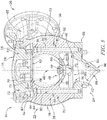
FIG. 5 is a cross-sectional view of the first stage damper ofFIGS. 1-4 , taken along the line 5-5 inFIG. 2 showing that the partitions extend between the outer chamber and the inner chamber and include holes for receiving long bolts which are prevented from being removed from their holes by the cap, and showing that the housing includes a base secured to the body by the long bolts; -
FIG. 6 is a bottom perspective view of the first stage damperFIGS. 1-5 showing that the base includes first alignment holes and second alignment holes for selectively receiving bolts to secure the base with the compressor, the first alignment holes are arranged to secure the base to the compressor in a first orientation and the second alignment holes are arranged to secure the base to the compressor in a second orientation; -
FIG. 7 is a side view of the first stage damper ofFIGS. 1-6 showing that the second stage damper is secured to the compressor using the first alignment holes to have the first orientation relative to the vertical line AA (in the orientation as shown); -
FIG. 8 is a side view of the first stage damper ofFIGS. 1-7 showing that the second stage damper is secured to the compressor using the second alignment holes to have the second orientation relative to the vertical line AA (in the orientation as shown); -
FIG. 9 is a closer perspective view of the second stage damper of the damper assembly ofFIG. 1 showing that the second stage damper includes an intake (bottom) connected to the compressor to receive fully compressed gas and a discharge (shown disconnected) for discharging fully compressed air having been dampened by the second stage damper; -
FIG. 10 is a cross-sectional view of the second stage damper ofFIGS. 1 and9 taken along the line 10-10 inFIG. 9 showing that the second stage damper includes an outer chamber, an inner chamber arranged within the outer chamber, and partitions that divide the outer chamber into sections that create parallel flow paths between the intake and the discharge, and showing that the damper includes a perforated damper plate arranged beyond an outlet of the inner chamber; -
FIG. 11 is an exploded perspective view of the second stage damper ofFIGS. 1 ,9, and 10 showing that the second stage damper includes a housing that forms a portion of the outer chamber, the housing includes a body, a cap, and a base formed integrally with the body; -
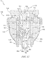
FIG. 12 is a cross-sectional view of the second stage damper ofFIGS. 1 and9-11 , taken along the line 12-12 inFIG. 9 showing that the partitions extend between the outer chamber and the inner chamber and include holes for receiving long bolts which are prevented from being removed from their holes by the cap. - While the concepts of the present disclosure are susceptible to various modifications and alternative forms, specific exemplary embodiments thereof have been shown by way of example in the drawings and will herein be described in detail. It should be understood, however, that there is no intent to limit the concepts of the present disclosure to the particular forms disclosed, but on the contrary, the intention is to cover all modifications, equivalents, and alternatives falling within the spirit and scope of the present disclosure.
- In the illustrative embodiment as shown in
FIG. 1 , a compressor assembly includes acompressor 10 having adamper system 12 for reducing pressure pulsations. Thedamper system 12 illustratively includes afirst stage damper 14 and asecond stage damper 16 each secured to thecompressor 10. Thecompressor 10 is illustratively embodiment as a displacement-type gas compressor, namely a screw compressor, but in some embodiments may include any fluid compressor. Thecompressor 10 illustratively includes twocompression stages - The
compressor 10 illustratively compresses a fluid (illustratively gas) in afirst compression stage 18 to an initial pressure (partially compressed). Thefirst stage damper 14 illustratively receives a flow of partially compressed fluid from thefirst compression stage 18, dampens and discharges the flow. In the illustrative embodiment, the flow discharged from the first stage damper (still partially compressed) reenters thecompressor 10 for further compression in asecond compression stage 20. In some embodiments, at least one portion of the flow discharged from thefirst stage damper 14 may be cooled by at least one cooler (interstage cooler) before reentering thecompressor 10, and/or may be distributed for use at the initial pressure. - The
compressor 10 illustratively compresses the flow of partially compressed fluid (discharged from the first stage damper 14) in asecond compression stage 20 to a final pressure (fully compressed). Thesecond stage damper 16 illustratively receives a flow of fully compressed fluid from thesecond compression stage 20, dampens and discharges the flow. In the illustrative embodiment, the flow discharged from the second stage damper 16 (fully compressed) is discharged for use at the final pressure. In some embodiments, the flow discharged from the second stage damper may be further conditioned, for example but without limitation, dehumidified according to final design requirements. - As mentioned above, the
compressor 10 is embodied as a displacement-type compressor. The compression stages 18, 20 are illustratively embodied as screw compression stages. Displacement compression can naturally result in incidental forces, for example but without limitation, pressure pulsations, due to the mechanics of operation. Pressure pulsations illustratively include naturally imposed pressure fluctuations (e.g., peaks and valleys) resultant from the cyclic nature of certain compression mechanics. Stresses on the compressor and/or related equipment can be reduced by damping (calming) the pressure fluctuations effectively. Effectively reducing the pressure pulsations can increase operational life, increase reliability, and/or reduce maintenance requirements. - In the illustrative embodiment as shown in
FIG. 2 , thefirst stage damper 14 illustratively includes ahousing 22 that forms anintake 24 and adischarge 26. Theintake 24 is illustratively connected to thecompressor 10 to receive a flow of partially compressed fluid. The flow of partially compressed fluid passes through thehousing 22 for dampening and exits through thedischarge 26. As mentioned above, the flow from thedischarge 26 illustratively returns to thecompressor 10 for further pressurization. Auxiliary components, such as piping components, returning the flow to thecompressor 10 from thedischarge 26, are implied but not shown to reveal detail. - As shown in
FIG. 3 , thefirst stage damper 14 illustratively includes anouter chamber 28 formed at least partially by thehousing 22. Theouter chamber 28 illustratively includes anouter cavity 30 defined therein. In the illustrative embodiment, theouter chamber 28 and theouter cavity 30 are each generally spherical and are generally symmetrical about acentral axis 15. Theouter chamber 28 illustratively includes aninlet 32 and anoutlet 34 each defined as openings of theouter chamber 28 that connect with theouter cavity 30. Partitions 38 (discussed below in more detail) illustratively divide theouter chamber 28 intosections 36. Thesections 36 illustratively connect with each other at opposite ends to formmanifolds outer chamber 28 with aninner chamber 44. - As shown in
FIG. 3 , theinner chamber 44 is illustratively arranged within theouter cavity 30 of theouter chamber 28. Theinner chamber 44 illustratively includes aninner cavity 46 defined therein. In the illustrative embodiment, theinner chamber 44 and the inner cavity are generally spherical and are generally symmetrical about thecentral axis 15. Theinner chamber 44 illustratively includes aninlet 48 and anoutlet 50 each embodied as openings of theinner chamber 44 that connect with theinner cavity 46. In the illustrative embodiment, theinlet 48 andoutlet 50 are arranged at opposite axial ends of theinner chamber 44 and connect with themanifolds - A
damper plate 52 is illustratively arranged within the manifold 42 near the outlet of theinner chamber 44 as shown inFIG. 3 . Thedamper plate 52 illustratively includesperforations 54 extending therethrough parallel to theaxis 15. In the illustrative embodiment, thedamper plate 52 is arranged spaced apart from theinner chamber 44 to define aclearance 56 therebetween. In the illustrative embodiment, portions of flow that pass through theinner chamber 44 and exit through theoutlet 50 illustratively form an inner flow, and can either pass through theperforations 54 or theclearance 56 into themanifold 42. Portions of flow that pass from theinlet 32 through thesections 36 of theouter chamber 28 illustratively form an outer flow. - As shown in
FIG. 3 , theinlet 48 of theinner chamber 44 illustratively connects with the manifold 40. Theinlet 48 illustratively includes four openings 58 (two of which are shown in the cross-sectional view ofFIG. 3 ) extending through awall 60 of theinner chamber 44. Thewall 60 at theinlet 48 illustratively has a generally convex shape on anouter side 62 that faces the manifold 40 and theinlet 32 of theouter chamber 28 to guide at least a portion of the incoming flow from theinlet 32 towards thesections 36. - As shown in
FIG. 3 , theopenings 58 of theinlet 48 illustratively penetrate through thewall 60 and connect the manifold 40 with theinner cavity 46. In the illustrative embodiment, theopenings 58 are distributed evenly about theaxis 15 and extend through thewall 60 in a direction that is generally parallel to theaxis 15 and complimentary to the major direction of flow through theinlet 32 of the outer chamber. Theinlet 48 illustratively forms a flow divider guiding a portion of flow through its openings 58 (and out through its outlet 50) and another portion of flow into thesections 36. The different portions of flow illustratively pass through thefirst stage damper 14 in parallel with each other between theintake 24 and thedischarge 26. - As shown in
FIG. 3 , thepartitions 38 illustratively extend between theouter chamber 28 and theinner chamber 44 to define thesections 36 of theouter chamber 28. Thepartitions 38 illustratively extend axially through theouter cavity 30. In the illustrative embodiment, thepartitions 38 are embodied as walls distributed evenly about theaxis 15 and provide structural support to thehousing 22 while separating theouter chamber 28 into thesections 36. Thesections 36 illustratively form distinct flow paths arranged in parallel with each other and connecting with each other to form themanifolds inner chamber 44, in combination with thedamper plate 52, illustratively dissipate pressure pulsations from thecompressor 10. The distinct flow paths provided by thesections 36 illustratively assist in reducing pressure pulsations within the total flow from thecompressor 10. - As shown in
FIG. 4 , thehousing 22 illustratively includes abody 62, acap 64, and a base 66 that collectively compose theouter chamber 28. Thecap 64 and the base illustratively attach to thebody 62 at opposite ends to enclose theouter chamber 28. Thedischarge 26 illustratively includes adischarge limb 68 that extends from thebody 62 and defines adischarge passage 69 extending therethrough and connecting with theoutlet 34 of theouter chamber 28. In the illustrative embodiment, thedischarge limb 68 extends from thebody 62 radially away from theaxis 15. Thedischarge passage 69 is illustratively directly connected with only asingle section 36 of theouter chamber 28 and communicates with the manifold 42 (and the other section 36) through thesingle section 36. - As best seen in
FIG. 5 , thepartitions 38 each include abase portion 70 and ahead portion 72. Eachbase portion 70 illustratively extends between theouter chamber 28 and theinner chamber 44 and includes anaxial end 74 arranged near the manifold 42. In the illustrative embodiment, eachbase portion 70 is illustratively formed integrally with each of the inner andouter chambers chambers head portion 72 illustratively extends from thecap 64 into theouter chamber 28 to aninner end 76 opposite theaxial end 74 of thebase portion 70. - As shown in
FIG. 5 , thedamper plate 52 is illustratively arranged between thebase portion 70 and thehead portion 72 of eachpartition 38 to define theclearance 56 with theinner chamber 44. Thedamper plate 52 is illustratively attached to eachhead portion 72 byfasteners 78 that extend through thedamper plate 52 and connect with therespective head portions 72. In the illustrative embodiment, thefasteners 78 are bolts having outer threads for engagement with complimentary inner threads of thehead portions 72. - As shown in
FIG. 5 , thebase portion 70 of eachpartition 38 illustratively includes afastener hole 80 extending axially therethrough from theaxial end 74 towards thebase 66. The fastener holes 80 are illustratively arranged to receivefasteners 82 therethrough to connect with thebase 66 for securing the base 66 to thebody 62. Eachfastener 82 illustratively includes ahead 84 that is recessed within a larger portion of thefastener hole 80. In the illustrative embodiment, thefasteners 82 are bolts having external threads for engagement with complimentary internal threads of thebase 66. - As shown in
FIG. 5 , thefasteners head portions partitions 38 and/or theinner chamber 44. As shown inFIG. 5 , thehead portion 72 of thepartitions 38 is arranged in close proximity to thefasteners 82 and theirfastener holes 80 and if any fastener 82 (or any portion thereof, for example, broken fragment) began to exit itsfastener hole 80 within thebase portion 70, thefastener 82 would contact therespective head portion 72 and be prevented from entering into the flow paths within the first stage damper 14 (and downstream). As shown inFIG. 5 , thebase portion 70 of eachpartition 38 and/or theinner chamber 44 are arranged in close proximity to thefasteners 78 and if anyfastener 78 began to exit connection with thehead portion 72, thefastener 78 would contact therespective base portion 70 and/or theinner chamber 44 and be prevented from entering into the flow paths within the first stage damper 14 (and downstream). Such interference arrangement of thefasteners dampers 14, 16 (and into the compressor 10) while thedampers - As best shown in
FIG. 5 , the base 66 illustratively forms theintake 24. Theintake 24 illustratively includes anintake limb 86 and anintake passage 88 extending through theintake limb 86 to receive partially compressed fluid from thecompressor 10. Theintake passage 88 is illustratively formed as an intake nozzle. Theintake passage 88 illustratively includes a reduceddiameter section 90 disposed at oneend 92, an increased diameter section 94 at an opposite end near theinlet 32, and a mid-section 95 extending between the reduceddiameter section 90 and the increased diameter section 94 with a taper to transition between thesections 90, 94 as shown inFIG. 5 . Theintake passage 88 illustratively includes curvature, as shown inFIG. 5 , which turns counter-clockwise proceeding from the reduceddiameter section 90 to the increased diameter section 94 to generally align with thecentral axis 15 near theinlet 32. - As shown in
FIG. 6 , thebase 66 of thehousing 22 illustratively includes a number of mountingholes 96 extending therethrough to receive main fasteners for connecting the base 66 with thecompressor 10. The base 66 illustratively includes attachment holes 98, 100 each arranged to correspond with one of thefasteners 82 for securing the base 66 with thebody 62. Each attachment holes 98, 100 illustratively includes the inner threads that are complimentary with the outer threads of thefasteners 82 for receiving thefasteners 82 secured therein. By selectively securing thefasteners 82 within the attachment holes 98, thebody 62 is secured to the base 66 with a first orientation (as shown inFIG. 7 ); alternatively, by securing thefasteners 82 within the attachment holes 100, the body is secure to the base 66 with a second orientation (as shown inFIG. 8 ). Thebody 62 can thus be selectively oriented relative to thebase 66. - In the illustratively embodiment as shown in
FIG. 7 , the first orientation is shown. In the first orientation as shown inFIG. 7 , thefirst stage damper 14 is arranged such that thedischarge 26 has a high steepness for connection downstream. For example but without limitation, in the first orientation of thefirst stage damper 14, thecompressor 10 is illustratively adapted for use as an air-cooled system in which an air-cooled intercooler cools the partially compressed air from thedischarge 26 of thefirst stage damper 14. In some embodiments, in the first orientation of thefirst stage damper 14, thecompressor 10 may be adapted for use with any suitable type of downstream connection, including but not limited to any suitable air/liquid/gas-cooled intercooler, treatment device, and/or transfer peripherals. In the first orientation, acenter line 25 of thedischarge 26 extends at an angle α from a vertical line AA (in the arrangement as shown inFIG. 7 ). In the illustrative embodiment, the angle is about 18 degrees, but in some embodiments, may be about 15 to about 20 degrees. - In the illustratively embodiment as shown in
FIG. 8 , the second orientation is shown. In the second orientation as shown inFIG. 8 , thefirst stage damper 14 is arranged is arranged such that thedischarge 26 has a moderate steepness for connection downstream. For example but without limitation, in the second orientation of thefirst stage damper 14, thecompressor 10 is illustratively adapted for use as an liquid-cooled system in which a liquid-cooled intercooler cools the partially compressed air from thedischarge 26 of thefirst stage damper 14. In some embodiments, in the second orientation of thefirst stage damper 14, thecompressor 10 may be adapted for use with any suitable type of downstream connection, including but not limited to any suitable air/liquid/gas-cooled intercooler, treatment device, and/or transfer peripherals. In the second orientation thecenter line 25 of thedischarge 26 extends at an angle β from a vertical line AA (in the arrangement as shown inFIG. 8 ). In the illustrative embodiment, the angle is about 20 degrees, but in some embodiments, may be about 18 to about 25 degrees. - In the illustrative embodiment as shown in
FIG. 9 , thesecond stage damper 16 illustratively includes ahousing 102 that forms anintake 104 and adischarge 106. Theintake 104 is illustratively connected to thecompressor 10 to receive a flow of fully compressed fluid. The flow of fully compressed fluid passes through thehousing 102 for dampening and exits through thedischarge 106. As mentioned above, the flow from thedischarge 106 is illustratively distributed for use. - As shown in
FIG. 10 , thesecond stage damper 16 illustratively includes anouter chamber 108 formed at least partially by thehousing 102. Theouter chamber 108 illustratively includes anouter cavity 110 defined therein. In the illustrative embodiment, theouter chamber 108 and theouter cavity 110 are each generally spherical and are generally symmetrical about acentral axis 35. Theouter chamber 108 illustratively includes aninlet 112 and anoutlet 114 each defined as openings of theouter chamber 108 that connect with theouter cavity 110. Partitions 38 (discussed below in more detail) illustratively divide theouter chamber 108 intosections 118. Thesections 118 illustratively connect with each other at opposite ends to formmanifolds outer chamber 108 with aninner chamber 124. - As shown in
FIG. 10 , theinner chamber 124 is illustratively arranged within theouter cavity 110 of theouter chamber 108. Theinner chamber 124 illustratively includes aninner cavity 126 defined therein. In the illustrative embodiment, theinner chamber 124 and theinner cavity 126 are generally spherical and are generally symmetrical about thecentral axis 35. Theinner chamber 124 illustratively includes aninlet 128 and anoutlet 130 each embodied as openings of theinner chamber 124 that connect withinner cavity 126. In the illustrative embodiment, theinlet 128 andoutlet 130 are arranged at opposite axial ends of theinner chamber 124 and connect with themanifolds - A
damper plate 132 is illustratively arranged within themanifold 122 near theoutlet 130 of theinner chamber 124 as shown inFIG. 10 . Thedamper plate 132 illustratively includes perforations 134 extending therethrough parallel to theaxis 35. In the illustrative embodiment, thedamper plate 132 is arranged spaced apart from theinner chamber 124 to define aclearance 136 therebetween. Flow that passes through theinner chamber 124 and exits through theoutlet 130 can either pass through the perforations 134 or theclearance 136 into themanifold 122. - As shown in
FIG. 10 , theinlet 128 of theinner chamber 124 illustratively connects with themanifold 120. Theinlet 128 illustratively includes four openings 138 (two of which are shown in the cross-sectional view ofFIG. 10 ) extending through awall 140 of theinner chamber 124. Thewall 140 at theinlet 128 illustratively has a generally convex shape on anouter side 142 that faces the manifold 120 and theinlet 112 of theouter chamber 108 to guide at least a portion of the incoming flow from theinlet 112 towards thesections 118. - As shown in
FIG. 10 , theopenings 138 of theinlet 128 illustratively penetrate through thewall 140 and connect the manifold 120 with theinner cavity 126. In the illustrative embodiment, theopenings 138 are distributed evenly about theaxis 35 and extend through thewall 140 in a direction that is generally parallel to theaxis 35 and complimentary to the major direction of flow through theinlet 112 of theouter chamber 108. Theinlet 128 of theinner chamber 124 illustratively forms a flow divider guiding a portion of flow through its openings 138 (and out through its outlet 130) and another portion of flow into thesections 118. The flow through thesections 118 illustratively forms an (outer) flow, and the flow through theinner cavity 126 illustratively forms another (inner) flow. The different portions of flow (outer and inner) illustratively pass through thesecond stage damper 16 in parallel with each other between theintake 104 and thedischarge 106. - As shown in
FIG. 10 , thepartitions 116 illustratively extend radially between theouter chamber 108 and theinner chamber 124 to define thesections 118 of theouter chamber 108. Thepartitions 116 illustratively extend axially through theouter cavity 110. In the illustrative embodiment, thepartitions 116 are embodied as four walls distributed evenly about theaxis 35. Thepartitions 116 illustratively provide structural support to thehousing 102 and apportion theouter chamber 108 into thesections 118. Thepartitions 116 support theinner chamber 124 and separate the flow intodifferent sections 118. In some embodiments, thepartitions 116 may include any number of walls and/or maybe arranged within uneven distribution about theaxis 35. Thesections 118 illustratively form distinct flow paths arranged in parallel with each other and connecting with each other to form themanifolds inner chamber 124, in combination with thedamper plate 52, illustratively dissipate pressure pulsations from thecompressor 10. The distinct flow paths provided by thesections 118 illustratively assist in reducing pressure pulsations within the total flow from thecompressor 10. - As shown in
FIG. 11 , thehousing 102 illustratively includes abody 142 and acap 144 that collectively compose theouter chamber 28. In the illustrative embodiment, unlike thehousing 22 of thefirst stage damper 14 which has a base 66 separated from thebody 62, thebody 142 of thesecond stage damper 16 forms a base 146 integrally therewith. In some embodiments, thebase 146 make be distinct from thebody 142. Thecap 144 illustratively attaches to thebody 142 on an opposite end from the base 146 to enclose theouter chamber 108. Thedischarge 106 illustratively includes adischarge passage 148 extending through thecap 144 and connecting with theoutlet 114 of theouter chamber 28. Thedischarge passage 148 is illustratively connected with the manifold 122 through theoutlet 114. In the illustrative embodiment, unlike thedischarge passage 69 of thefirst stage damper 14, theoutlet 114 is not positioned with anysingle section 118. Thedischarge passage 148 illustratively communicates with eachsection 118 through themanifold 122. - As shown in
FIGS. 10 and11 , thepartitions 116 each include abase portion 150 and a head portion 152 (best shown inFIG. 10 ). Eachbase portion 150 illustratively extends radially between theouter chamber 108 and theinner chamber 124 and includes anaxial end 154 arranged near themanifold 122. In the illustrative embodiment, eachbase portion 150 is illustratively formed integrally with each of the outer andinner chambers chambers head portion 152 illustratively extends from thecap 144 into theouter chamber 108 to aninner end 156 opposite theaxial end 154 of thebase portion 150. - As shown in
FIG. 10 , thedamper plate 132 is illustratively arranged between thebase portion 150 and thehead portion 152 of eachpartition 116 to define theclearance 136 with theinner chamber 124. Thedamper plate 132 is illustratively attached to eachhead portion 152 byfasteners 158 that extend through thedamper plate 132 and connect with therespective head portions 152. In the illustrative embodiment, thefasteners 158 are bolts having outer threads for engagement with complimentary inner threads of thehead portions 152. - As shown in
FIG. 12 , thebase portion 150 of eachpartition 116 illustratively includes afastener hole 160 extending axially therethrough from theaxial end 154 through thebase 146. The fastener holes 160 are illustratively arranged to receivefasteners 162 therethrough to connect with thecompressor 10 for securing thesecond stage damper 16 thereto. Eachfastener 162 illustratively includes ahead 164 that is recessed within a larger portion of thefastener hole 160. In the illustrative embodiment, thefasteners 162 are bolts having external threads for engagement with complimentary internal threads of thecompressor 10. - As shown in
FIG. 12 , thefasteners head portions partitions 116 and/or theinner chamber 124. As shown inFIG. 12 , thehead portion 152 of thepartitions 116 is arranged in close proximity to thefasteners 162 and theirfastener holes 160 and if any fastener 162 (or any portion thereof, for example, broken fragment) began to exit its fastener hole 180 within thebase portion 150, thefastener 162 would contact therespective head portion 152 and be prevented from entering into the flow paths within the second stage damper 16 (and downstream). As shown inFIG. 12 , thebase portion 150 of eachpartition 116 and/or theinner chamber 124 are arranged in close proximity to thefasteners 158 and if anyfastener 158 began to exit from connection with thehead portion 152, thefastener 158 would contact therespective base portion 150 and/or theinner chamber 124 and be prevented from entering into the flow paths within the second stage damper 16 (and downstream). Such interference arrangement of thefasteners 158, 182 can prevent accidental entrainment of fasteners into the flow paths of thedampers 14, 16 (and into the compressor 10) while thedampers - As best shown in
FIG. 12 , the base 146 illustratively forms theintake 104. Theintake 104 illustratively includes anintake limb 184 and anintake passage 186 extending through theintake limb 184 to receive partially compressed fluid from thecompressor 10. Theintake passage 186 is illustratively formed as an intake nozzle. Theintake passage 186 illustratively includes a reduceddiameter section 188 disposed at oneend 190, an increaseddiameter section 192 at an opposite end near theinlet 112, and a mid-section 194 extending between the reduceddiameter section 188 and the increaseddiameter section 192 with a taper to transition between thesections FIG. 12 , unlike theintake passage 88 of thefirst stage damper 14, theintake passage 186 is straight (though with taper) and generally aligns with thecentral axis 35 proceeding from the reduceddiameter section 188 to the increaseddiameter section 192. - The present disclosure includes portions of flow through sections of outer chambers and portions of flow through inner chambers running in parallel with each other. Some of these parallel flows can be directed through a perforated damper plate. The parallel flows can increase dampening performance. According to the present disclosure, the pulsations and/or other incidental forces and/or effects of displacement-type compressors can be controlled and/or reduced effectively.
- While certain illustrative embodiments have been described in detail in the figures and the foregoing description, such an illustration and description is to be considered as exemplary and not restrictive in character, it being understood that only illustrative embodiments have been shown and described and that all changes and modifications that come within the spirit of the disclosure are desired to be protected. There are a plurality of advantages of the present disclosure arising from the various features of the apparatus, systems, and methods described herein. It will be noted that alternative embodiments of the apparatus, systems, and methods of the present disclosure may not include all of the features described yet still benefit from at least some of the advantages of such features. Those of ordinary skill in the art may readily devise their own implementations of the apparatus, systems, and methods that incorporate one or more of the features of the present disclosure.
- For the avoidance of doubt, the present application extends to the subject-matter described in the following numbered clauses:
- 1. A damper for reducing pulsation from a compressor, the damper comprising:
- an outer chamber defining an outer cavity therein, the outer chamber being arranged to pass flow from an inlet to an outlet thereof,
- an inner chamber arranged within the outer cavity and defining an inner cavity therein, the inner chamber being arranged to pass flow from an inlet to an outlet thereof, and
- a number of partitions dividing the outer chamber into sections, the number of partitions each extending between the outer chamber and the inner chamber.
- 2. The damper of Clause 1, wherein the sections of the outer chamber are each connected with each other near the inlet of the inner chamber to form an inlet manifold and are connected with each other near the outlet of the inner chamber to form an outlet manifold.
- 3. The damper of Clause 2, wherein the sections of the outer chamber each extend between the respective inlet and outlet manifolds and define parallel flow paths.
- 4. The damper of Clause 2 or 3, wherein the inlet of the inner chamber is connected with the inlet manifold and the outlet of the inner chamber is connected with the outlet manifold.
- 5. The damper of any preceding Clause, wherein a housing forms at least a portion of the outer chamber, the housing including a body and a cap fastened to the body to define at least a portion of the outer cavity.
- 6. The damper of Clause 5, wherein the body forms a base portion of the outer chamber and forms the inner chamber.
- 7. The damper of Clause 6, wherein the cap forms a head portion of the outer chamber.
- 8. The damper of any of Clauses 5-7, wherein the body forms a base portion of each of the number of partitions.
- 9. The damper of Clause 8, wherein the cap forms a head portion of each of the number of partitions.
- 10. The damper of Clause 9, wherein each base portion includes a fastener hole defined therethrough for receiving a fastener to secure the body with the compressor.
- 11. The damper of
Clause 10, wherein the head portion of each of the number of partitions is arranged to prevent removal of the fastener from the fastener hole of the corresponding base portion. - 12. The damper of any of Clauses 9-11, further comprising a damper plate arranged between the base portion and the head portion of each of the number of partitions.
- 13. The damper of
Clause 12, wherein the damper plate is a perforated plate arranged to span across the outlet of the inner chamber to receive at least a portion of flow therethrough. - 14. The damper of
Clause 12 or 13, wherein the damper plate is attached to the head portion of the number of partitions with at least one fastener and at least one of the inner chamber and the base portions of the number of partitions are arranged to prevent removal of the at least one fastener when the cap is fastened to the body. - 15. A damper for reducing pulsation from a compressor, the damper comprising:
- an outer chamber defining an outer cavity therein, the outer chamber being arranged to pass flow from an inlet to an outlet thereof,
- an inner chamber arranged within the outer cavity and defining an inner cavity therein, the inner chamber being arranged to pass flow from an inlet to an outlet thereof, and
- a number of partitions dividing the outer chamber into sections that are each connected with the inlet and outlet of the outer chamber to form parallel flow paths,
- wherein the inlet of the inner chamber comprises a number of inlet openings defined through an inlet wall of the inner chamber.
- 16. The damper of
Clause 15, wherein the inlet wall has a conical shape that is convex on an outer side thereof to guide at least some flow through the sections. - 17. The damper of
Clause - 18. The damper of Clause 17, further comprising a perforated plate arranged near the outlet of the inner chamber, wherein the second flow passage is further defined through the perforated plate.
- 19. A damper for reducing pulsation from a compressor, the damper comprising:
- an outer chamber defining an outer cavity therein, the outer chamber being arranged to pass flow from an inlet to an outlet thereof,
- an inner chamber arranged within the outer cavity and defining an inner cavity therein, the inner chamber being arranged to pass flow from an inlet to an outlet thereof, and
- a number of partitions dividing the outer chamber into sections that are each connected with the inlet and outlet of the outer chamber to form parallel flow paths,
- wherein a housing forms at least a portion of the outer chamber, the housing includes a body and a cap attached to the body to define at least a portion of the outer cavity.
- 20. The damper of Clause 19, wherein the housing further includes a base having an intake passage defined therethrough, the intake passage being connected with the inlet of the outer chamber to receive flow from the compressor.
- 21. The damper of
Clause 20, wherein the intake passage forms an intake nozzle. - 22. The damper of
Clause 20 or 21, wherein the base is integrally formed with the body. - 23. The damper of any of Clauses 19-22, wherein the sections are connected to each other to form an outlet manifold and the outlet of the outer chamber is arranged within only one of the sections.
- 24. The damper of Clause 23, wherein the housing includes a discharge limb extending from the outer chamber and defining a discharge passage that extends from the outlet of the outer chamber through the discharge limb to expel flow.
- 25. A damper system for reducing pulsation from a compressor, the damper system comprising:
- a first stage damper, and
- a second stage damper,
- the first and second stage dampers each comprising:
- an outer chamber defining an outer cavity therein, the outer chamber being arranged to pass flow from an inlet to an outlet thereof,
- an inner chamber arranged within the outer cavity and defining an inner cavity therein, the inner chamber being arranged to pass flow from an inlet to an outlet thereof.
- 26. The damper system of
Clause 25, wherein at least one of the first and second stage dampers include a number of partitions dividing the respective outer chamber into sections that are each connected with the inlet and the outlet of the outer chamber to form parallel flow paths. - 27. The damper system of
Clause
Claims (15)
- A damper for reducing pulsation from a compressor, the damper comprising:an outer chamber defining an outer cavity therein, the outer chamber being arranged to pass flow from an inlet to an outlet thereof,an inner chamber arranged within the outer cavity and defining an inner cavity therein, the inner chamber being arranged to pass flow from an inlet to an outlet thereof, anda number of partitions dividing the outer chamber into sections, the number of partitions each extending between the outer chamber and the inner chamber.
- The damper of claim 1, wherein the sections of the outer chamber are each connected with each other near the inlet of the inner chamber to form an inlet manifold and are connected with each other near the outlet of the inner chamber to form an outlet manifold.
- The damper of claim 2, wherein the sections of the outer chamber each extend between the respective inlet and outlet manifolds and define parallel flow paths.
- The damper of claim 2 or 3, wherein the inlet of the inner chamber is connected with the inlet manifold and the outlet of the inner chamber is connected with the outlet manifold.
- The damper of any preceding claim, wherein a housing forms at least a portion of the outer chamber, the housing including a body and a cap fastened to the body to define at least a portion of the outer cavity.
- The damper of claim 5, wherein the body forms a base portion of the outer chamber and forms the inner chamber.
- The damper of claim 6, wherein the cap forms a head portion of the outer chamber.
- The damper of any of claims 5-7, wherein the body forms a base portion of each of the number of partitions.
- The damper of claim 8, wherein the cap forms a head portion of each of the number of partitions.
- The damper of claim 9, wherein each base portion includes a fastener hole defined therethrough for receiving a fastener to secure the body with the compressor.
- The damper of claim 10, wherein the head portion of each of the number of partitions is arranged to prevent removal of the fastener from the fastener hole of the corresponding base portion.
- The damper of any of claims 9-11, further comprising a damper plate arranged between the base portion and the head portion of each of the number of partitions.
- The damper of claim 12, wherein the damper plate is a perforated plate arranged to span across the outlet of the inner chamber to receive at least a portion of flow therethrough.
- The damper of claim 12 or 13, wherein the damper plate is attached to the head portion of the number of partitions with at least one fastener and at least one of the inner chamber and the base portions of the number of partitions are arranged to prevent removal of the at least one fastener when the cap is fastened to the body.
- A damper system for reducing pulsation from a compressor, the damper system comprising:a first stage damper in accordance with any of claims 1-14, anda second stage damper in accordance with any of claims 1-14.
Applications Claiming Priority (1)
| Application Number | Priority Date | Filing Date | Title |
|---|---|---|---|
| US15/282,149 US10180140B2 (en) | 2016-09-30 | 2016-09-30 | Pulsation damper for compressors |
Publications (2)
| Publication Number | Publication Date |
|---|---|
| EP3301299A1 true EP3301299A1 (en) | 2018-04-04 |
| EP3301299B1 EP3301299B1 (en) | 2020-02-19 |
Family
ID=59772496
Family Applications (1)
| Application Number | Title | Priority Date | Filing Date |
|---|---|---|---|
| EP17189170.8A Active EP3301299B1 (en) | 2016-09-30 | 2017-09-04 | Pulsation damper for compressors |
Country Status (3)
| Country | Link |
|---|---|
| US (1) | US10180140B2 (en) |
| EP (1) | EP3301299B1 (en) |
| CN (1) | CN107882733B (en) |
Citations (6)
| Publication number | Priority date | Publication date | Assignee | Title |
|---|---|---|---|---|
| US4050539A (en) * | 1975-09-13 | 1977-09-27 | Teruo Kashiwara | Exhaust apparatus for internal combustion engine |
| DE19737799A1 (en) * | 1996-10-09 | 1998-04-23 | Mando Machine Co Ltd | Silencer for high-pressure output of compressor in vehicle air conditioner |
| WO2005008069A1 (en) * | 2003-07-22 | 2005-01-27 | Calsonic Kansei Corporation | Compressor |
| US20060124385A1 (en) * | 2004-12-10 | 2006-06-15 | Ingersoll-Rand Company | Modular pressure pulsation dampener |
| US20120171069A1 (en) * | 2011-01-05 | 2012-07-05 | Paul Xiubao Huang | Screw compressor with a shunt pulsation trap |
| US20150198179A1 (en) * | 2014-01-16 | 2015-07-16 | Ingersoll-Rand Company | Compressor system with pressure pulsation dampener and check valve |
Family Cites Families (22)
| Publication number | Priority date | Publication date | Assignee | Title |
|---|---|---|---|---|
| US2990907A (en) | 1959-06-11 | 1961-07-04 | Wilhelm S Everett | Acoustic filter |
| US4109751A (en) * | 1976-08-26 | 1978-08-29 | Deere & Company | Noise silencer |
| SE438009B (en) * | 1978-10-03 | 1985-03-25 | Dolmar Maschfab | INSULATION AND / OR EXHAUST SILENCE AT FAST ENGINE COMBUSTION ENGINES |
| JP2895407B2 (en) * | 1994-12-01 | 1999-05-24 | 本田技研工業株式会社 | Intake silencer |
| US6220839B1 (en) | 1999-07-07 | 2001-04-24 | Copeland Corporation | Scroll compressor discharge muffler |
| JP2004270559A (en) * | 2003-03-10 | 2004-09-30 | Honda Motor Co Ltd | Vehicle intake system |
| CN1542284A (en) | 2003-05-01 | 2004-11-03 | 乐金电子(天津)电器有限公司 | Porous intervention type silencer for rotary compressor |
| KR20060024739A (en) | 2004-09-14 | 2006-03-17 | 삼성전자주식회사 | Multi-cylinder compressor |
| US7549509B2 (en) | 2005-04-21 | 2009-06-23 | Ingersoll-Rand Company | Double throat pulsation dampener for a compressor |
| EP1715188A1 (en) | 2005-04-22 | 2006-10-25 | Kaeser Kompressoren GmbH | Noise attenuator designed and meant for a compressor |
| EP1715189B1 (en) * | 2005-04-22 | 2013-12-04 | Kaeser Kompressoren AG | Noise attenuator designed and meant for a compressor |
| EP1876358B1 (en) | 2006-07-03 | 2010-02-10 | LG Electronics Inc. | Scroll compressor with muffler |
| CN101105177A (en) | 2006-07-13 | 2008-01-16 | Lg电子株式会社 | Silencer for scroll compressor |
| US9404499B2 (en) | 2006-12-01 | 2016-08-02 | Emerson Climate Technologies, Inc. | Dual chamber discharge muffler |
| CN101398005A (en) | 2007-09-28 | 2009-04-01 | 乐金电子(天津)电器有限公司 | Silencing apparatus of compressor |
| WO2009045187A1 (en) | 2007-10-01 | 2009-04-09 | Carrier Corporation | Screw compressor pulsation damper |
| CN101806251B (en) | 2010-03-25 | 2012-08-22 | 北京航空航天大学 | Starting control device of micro gas turbine and starting control method |
| US9551342B2 (en) * | 2014-05-23 | 2017-01-24 | Paul Xiubao Huang | Scroll compressor with a shunt pulsation trap |
| US9732754B2 (en) | 2011-06-07 | 2017-08-15 | Hi-Bar Blowers, Inc. | Shunt pulsation trap for positive-displacement machinery |
| KR102160310B1 (en) * | 2013-03-06 | 2020-09-28 | 에이비비 터보 시스템즈 아게 | Sound attenuator of an exhaust gas turbocharger |
| US9951761B2 (en) | 2014-01-16 | 2018-04-24 | Ingersoll-Rand Company | Aerodynamic pressure pulsation dampener |
| CN104454548B (en) | 2014-12-22 | 2017-02-01 | 广东美芝制冷设备有限公司 | Rotary compressor |
-
2016
- 2016-09-30 US US15/282,149 patent/US10180140B2/en active Active
-
2017
- 2017-09-04 EP EP17189170.8A patent/EP3301299B1/en active Active
- 2017-09-26 CN CN201710880509.3A patent/CN107882733B/en active Active
Patent Citations (6)
| Publication number | Priority date | Publication date | Assignee | Title |
|---|---|---|---|---|
| US4050539A (en) * | 1975-09-13 | 1977-09-27 | Teruo Kashiwara | Exhaust apparatus for internal combustion engine |
| DE19737799A1 (en) * | 1996-10-09 | 1998-04-23 | Mando Machine Co Ltd | Silencer for high-pressure output of compressor in vehicle air conditioner |
| WO2005008069A1 (en) * | 2003-07-22 | 2005-01-27 | Calsonic Kansei Corporation | Compressor |
| US20060124385A1 (en) * | 2004-12-10 | 2006-06-15 | Ingersoll-Rand Company | Modular pressure pulsation dampener |
| US20120171069A1 (en) * | 2011-01-05 | 2012-07-05 | Paul Xiubao Huang | Screw compressor with a shunt pulsation trap |
| US20150198179A1 (en) * | 2014-01-16 | 2015-07-16 | Ingersoll-Rand Company | Compressor system with pressure pulsation dampener and check valve |
Also Published As
| Publication number | Publication date |
|---|---|
| US10180140B2 (en) | 2019-01-15 |
| US20180094629A1 (en) | 2018-04-05 |
| CN107882733A (en) | 2018-04-06 |
| CN107882733B (en) | 2020-11-17 |
| EP3301299B1 (en) | 2020-02-19 |
Similar Documents
| Publication | Publication Date | Title |
|---|---|---|
| AU2020281134B2 (en) | Vacuum pump with filtering element | |
| CN102985695B (en) | Multi-stage low pressure drop muffler | |
| RU2589978C2 (en) | Refrigerating compressor | |
| JP6310879B2 (en) | Oil jet equipment | |
| EP1700037B1 (en) | Compressor discharge chamber with baffle plate | |
| US10180140B2 (en) | Pulsation damper for compressors | |
| US2490493A (en) | Attenuation pulsation dampener | |
| US7494328B2 (en) | NVH and gas pulsation reduction in AC compressor | |
| US2707033A (en) | Pulsation dampeners | |
| CN221170014U (en) | Compressor with a compressor body having a rotor with a rotor shaft | |
| US9051724B2 (en) | Flow regulating device | |
| CN117329741B (en) | Liquid separator and compressor with it | |
| JP7028645B2 (en) | Shock absorber | |
| US20150315948A1 (en) | Modular aftertreatment assembly | |
| CN211623830U (en) | Vibration damper for condenser | |
| US20210115926A1 (en) | Modular compressor discharge system | |
| JPH04366090A (en) | Surging controller | |
| CN219262493U (en) | Muffler and vehicle | |
| CN112855623B (en) | Vibration damping device for condenser | |
| HU222975B1 (en) | Air cleaner for internal combustion engines | |
| EP3346140B1 (en) | Fixing bolt for stationary member, and centrifugal compressor | |
| WO2023112177A1 (en) | Silencer and vacuum evacuation device | |
| CN117894287A (en) | Silencing structure and oxygenerator | |
| JP2018123774A (en) | Filter device | |
| CN113007067A (en) | Silencer and compressor |
Legal Events
| Date | Code | Title | Description |
|---|---|---|---|
| PUAI | Public reference made under article 153(3) epc to a published international application that has entered the european phase |
Free format text: ORIGINAL CODE: 0009012 |
|
| STAA | Information on the status of an ep patent application or granted ep patent |
Free format text: STATUS: THE APPLICATION HAS BEEN PUBLISHED |
|
| AK | Designated contracting states |
Kind code of ref document: A1 Designated state(s): AL AT BE BG CH CY CZ DE DK EE ES FI FR GB GR HR HU IE IS IT LI LT LU LV MC MK MT NL NO PL PT RO RS SE SI SK SM TR |
|
| AX | Request for extension of the european patent |
Extension state: BA ME |
|
| STAA | Information on the status of an ep patent application or granted ep patent |
Free format text: STATUS: REQUEST FOR EXAMINATION WAS MADE |
|
| 17P | Request for examination filed |
Effective date: 20181004 |
|
| RBV | Designated contracting states (corrected) |
Designated state(s): AL AT BE BG CH CY CZ DE DK EE ES FI FR GB GR HR HU IE IS IT LI LT LU LV MC MK MT NL NO PL PT RO RS SE SI SK SM TR |
|
| STAA | Information on the status of an ep patent application or granted ep patent |
Free format text: STATUS: EXAMINATION IS IN PROGRESS |
|
| 17Q | First examination report despatched |
Effective date: 20190418 |
|
| GRAP | Despatch of communication of intention to grant a patent |
Free format text: ORIGINAL CODE: EPIDOSNIGR1 |
|
| STAA | Information on the status of an ep patent application or granted ep patent |
Free format text: STATUS: GRANT OF PATENT IS INTENDED |
|
| INTG | Intention to grant announced |
Effective date: 20190913 |
|
| GRAS | Grant fee paid |
Free format text: ORIGINAL CODE: EPIDOSNIGR3 |
|
| GRAA | (expected) grant |
Free format text: ORIGINAL CODE: 0009210 |
|
| STAA | Information on the status of an ep patent application or granted ep patent |
Free format text: STATUS: THE PATENT HAS BEEN GRANTED |
|
| AK | Designated contracting states |
Kind code of ref document: B1 Designated state(s): AL AT BE BG CH CY CZ DE DK EE ES FI FR GB GR HR HU IE IS IT LI LT LU LV MC MK MT NL NO PL PT RO RS SE SI SK SM TR |
|
| REG | Reference to a national code |
Ref country code: CH Ref legal event code: EP |
|
| REG | Reference to a national code |
Ref country code: DE Ref legal event code: R096 Ref document number: 602017011889 Country of ref document: DE |
|
| REG | Reference to a national code |
Ref country code: AT Ref legal event code: REF Ref document number: 1235274 Country of ref document: AT Kind code of ref document: T Effective date: 20200315 |
|
| REG | Reference to a national code |
Ref country code: IE Ref legal event code: FG4D |
|
| RAP2 | Party data changed (patent owner data changed or rights of a patent transferred) |
Owner name: INGERSOLL-RAND INDUSTRIAL U.S., INC. |
|
| REG | Reference to a national code |
Ref country code: NL Ref legal event code: MP Effective date: 20200219 |
|
| PG25 | Lapsed in a contracting state [announced via postgrant information from national office to epo] |
Ref country code: NO Free format text: LAPSE BECAUSE OF FAILURE TO SUBMIT A TRANSLATION OF THE DESCRIPTION OR TO PAY THE FEE WITHIN THE PRESCRIBED TIME-LIMIT Effective date: 20200519 Ref country code: FI Free format text: LAPSE BECAUSE OF FAILURE TO SUBMIT A TRANSLATION OF THE DESCRIPTION OR TO PAY THE FEE WITHIN THE PRESCRIBED TIME-LIMIT Effective date: 20200219 Ref country code: RS Free format text: LAPSE BECAUSE OF FAILURE TO SUBMIT A TRANSLATION OF THE DESCRIPTION OR TO PAY THE FEE WITHIN THE PRESCRIBED TIME-LIMIT Effective date: 20200219 |
|
| REG | Reference to a national code |
Ref country code: LT Ref legal event code: MG4D |
|
| PG25 | Lapsed in a contracting state [announced via postgrant information from national office to epo] |
Ref country code: HR Free format text: LAPSE BECAUSE OF FAILURE TO SUBMIT A TRANSLATION OF THE DESCRIPTION OR TO PAY THE FEE WITHIN THE PRESCRIBED TIME-LIMIT Effective date: 20200219 Ref country code: SE Free format text: LAPSE BECAUSE OF FAILURE TO SUBMIT A TRANSLATION OF THE DESCRIPTION OR TO PAY THE FEE WITHIN THE PRESCRIBED TIME-LIMIT Effective date: 20200219 Ref country code: LV Free format text: LAPSE BECAUSE OF FAILURE TO SUBMIT A TRANSLATION OF THE DESCRIPTION OR TO PAY THE FEE WITHIN THE PRESCRIBED TIME-LIMIT Effective date: 20200219 Ref country code: BG Free format text: LAPSE BECAUSE OF FAILURE TO SUBMIT A TRANSLATION OF THE DESCRIPTION OR TO PAY THE FEE WITHIN THE PRESCRIBED TIME-LIMIT Effective date: 20200519 Ref country code: IS Free format text: LAPSE BECAUSE OF FAILURE TO SUBMIT A TRANSLATION OF THE DESCRIPTION OR TO PAY THE FEE WITHIN THE PRESCRIBED TIME-LIMIT Effective date: 20200619 Ref country code: GR Free format text: LAPSE BECAUSE OF FAILURE TO SUBMIT A TRANSLATION OF THE DESCRIPTION OR TO PAY THE FEE WITHIN THE PRESCRIBED TIME-LIMIT Effective date: 20200520 |
|
| PG25 | Lapsed in a contracting state [announced via postgrant information from national office to epo] |
Ref country code: NL Free format text: LAPSE BECAUSE OF FAILURE TO SUBMIT A TRANSLATION OF THE DESCRIPTION OR TO PAY THE FEE WITHIN THE PRESCRIBED TIME-LIMIT Effective date: 20200219 |
|
| PG25 | Lapsed in a contracting state [announced via postgrant information from national office to epo] |
Ref country code: RO Free format text: LAPSE BECAUSE OF FAILURE TO SUBMIT A TRANSLATION OF THE DESCRIPTION OR TO PAY THE FEE WITHIN THE PRESCRIBED TIME-LIMIT Effective date: 20200219 Ref country code: CZ Free format text: LAPSE BECAUSE OF FAILURE TO SUBMIT A TRANSLATION OF THE DESCRIPTION OR TO PAY THE FEE WITHIN THE PRESCRIBED TIME-LIMIT Effective date: 20200219 Ref country code: SK Free format text: LAPSE BECAUSE OF FAILURE TO SUBMIT A TRANSLATION OF THE DESCRIPTION OR TO PAY THE FEE WITHIN THE PRESCRIBED TIME-LIMIT Effective date: 20200219 Ref country code: ES Free format text: LAPSE BECAUSE OF FAILURE TO SUBMIT A TRANSLATION OF THE DESCRIPTION OR TO PAY THE FEE WITHIN THE PRESCRIBED TIME-LIMIT Effective date: 20200219 Ref country code: LT Free format text: LAPSE BECAUSE OF FAILURE TO SUBMIT A TRANSLATION OF THE DESCRIPTION OR TO PAY THE FEE WITHIN THE PRESCRIBED TIME-LIMIT Effective date: 20200219 Ref country code: DK Free format text: LAPSE BECAUSE OF FAILURE TO SUBMIT A TRANSLATION OF THE DESCRIPTION OR TO PAY THE FEE WITHIN THE PRESCRIBED TIME-LIMIT Effective date: 20200219 Ref country code: PT Free format text: LAPSE BECAUSE OF FAILURE TO SUBMIT A TRANSLATION OF THE DESCRIPTION OR TO PAY THE FEE WITHIN THE PRESCRIBED TIME-LIMIT Effective date: 20200712 Ref country code: EE Free format text: LAPSE BECAUSE OF FAILURE TO SUBMIT A TRANSLATION OF THE DESCRIPTION OR TO PAY THE FEE WITHIN THE PRESCRIBED TIME-LIMIT Effective date: 20200219 Ref country code: SM Free format text: LAPSE BECAUSE OF FAILURE TO SUBMIT A TRANSLATION OF THE DESCRIPTION OR TO PAY THE FEE WITHIN THE PRESCRIBED TIME-LIMIT Effective date: 20200219 |
|
| REG | Reference to a national code |
Ref country code: AT Ref legal event code: MK05 Ref document number: 1235274 Country of ref document: AT Kind code of ref document: T Effective date: 20200219 |
|
| REG | Reference to a national code |
Ref country code: DE Ref legal event code: R097 Ref document number: 602017011889 Country of ref document: DE |
|
| PLBE | No opposition filed within time limit |
Free format text: ORIGINAL CODE: 0009261 |
|
| STAA | Information on the status of an ep patent application or granted ep patent |
Free format text: STATUS: NO OPPOSITION FILED WITHIN TIME LIMIT |
|
| REG | Reference to a national code |
Ref country code: DE Ref legal event code: R082 Ref document number: 602017011889 Country of ref document: DE Representative=s name: MURGITROYD GERMANY PATENTANWALTSGESELLSCHAFT M, DE Ref country code: DE Ref legal event code: R082 Ref document number: 602017011889 Country of ref document: DE Representative=s name: HL KEMPNER PATENTANWALT, RECHTSANWALT, SOLICIT, DE Ref country code: DE Ref legal event code: R082 Ref document number: 602017011889 Country of ref document: DE Representative=s name: MURGITROYD & COMPANY, DE |
|
| 26N | No opposition filed |
Effective date: 20201120 |
|
| PG25 | Lapsed in a contracting state [announced via postgrant information from national office to epo] |
Ref country code: IT Free format text: LAPSE BECAUSE OF FAILURE TO SUBMIT A TRANSLATION OF THE DESCRIPTION OR TO PAY THE FEE WITHIN THE PRESCRIBED TIME-LIMIT Effective date: 20200219 Ref country code: AT Free format text: LAPSE BECAUSE OF FAILURE TO SUBMIT A TRANSLATION OF THE DESCRIPTION OR TO PAY THE FEE WITHIN THE PRESCRIBED TIME-LIMIT Effective date: 20200219 |
|
| PG25 | Lapsed in a contracting state [announced via postgrant information from national office to epo] |
Ref country code: PL Free format text: LAPSE BECAUSE OF FAILURE TO SUBMIT A TRANSLATION OF THE DESCRIPTION OR TO PAY THE FEE WITHIN THE PRESCRIBED TIME-LIMIT Effective date: 20200219 Ref country code: SI Free format text: LAPSE BECAUSE OF FAILURE TO SUBMIT A TRANSLATION OF THE DESCRIPTION OR TO PAY THE FEE WITHIN THE PRESCRIBED TIME-LIMIT Effective date: 20200219 |
|
| REG | Reference to a national code |
Ref country code: DE Ref legal event code: R082 Ref document number: 602017011889 Country of ref document: DE Representative=s name: MURGITROYD GERMANY PATENTANWALTSGESELLSCHAFT M, DE Ref country code: DE Ref legal event code: R082 Ref document number: 602017011889 Country of ref document: DE Representative=s name: MURGITROYD & COMPANY, DE |
|
| REG | Reference to a national code |
Ref country code: CH Ref legal event code: PL |
|
| REG | Reference to a national code |
Ref country code: BE Ref legal event code: MM Effective date: 20200930 |
|
| PG25 | Lapsed in a contracting state [announced via postgrant information from national office to epo] |
Ref country code: LU Free format text: LAPSE BECAUSE OF NON-PAYMENT OF DUE FEES Effective date: 20200904 |
|
| PG25 | Lapsed in a contracting state [announced via postgrant information from national office to epo] |
Ref country code: BE Free format text: LAPSE BECAUSE OF NON-PAYMENT OF DUE FEES Effective date: 20200930 Ref country code: CH Free format text: LAPSE BECAUSE OF NON-PAYMENT OF DUE FEES Effective date: 20200930 Ref country code: IE Free format text: LAPSE BECAUSE OF NON-PAYMENT OF DUE FEES Effective date: 20200904 Ref country code: LI Free format text: LAPSE BECAUSE OF NON-PAYMENT OF DUE FEES Effective date: 20200930 |
|
| PG25 | Lapsed in a contracting state [announced via postgrant information from national office to epo] |
Ref country code: TR Free format text: LAPSE BECAUSE OF FAILURE TO SUBMIT A TRANSLATION OF THE DESCRIPTION OR TO PAY THE FEE WITHIN THE PRESCRIBED TIME-LIMIT Effective date: 20200219 Ref country code: MT Free format text: LAPSE BECAUSE OF FAILURE TO SUBMIT A TRANSLATION OF THE DESCRIPTION OR TO PAY THE FEE WITHIN THE PRESCRIBED TIME-LIMIT Effective date: 20200219 Ref country code: CY Free format text: LAPSE BECAUSE OF FAILURE TO SUBMIT A TRANSLATION OF THE DESCRIPTION OR TO PAY THE FEE WITHIN THE PRESCRIBED TIME-LIMIT Effective date: 20200219 |
|
| PG25 | Lapsed in a contracting state [announced via postgrant information from national office to epo] |
Ref country code: MK Free format text: LAPSE BECAUSE OF FAILURE TO SUBMIT A TRANSLATION OF THE DESCRIPTION OR TO PAY THE FEE WITHIN THE PRESCRIBED TIME-LIMIT Effective date: 20200219 Ref country code: MC Free format text: LAPSE BECAUSE OF FAILURE TO SUBMIT A TRANSLATION OF THE DESCRIPTION OR TO PAY THE FEE WITHIN THE PRESCRIBED TIME-LIMIT Effective date: 20200219 Ref country code: AL Free format text: LAPSE BECAUSE OF FAILURE TO SUBMIT A TRANSLATION OF THE DESCRIPTION OR TO PAY THE FEE WITHIN THE PRESCRIBED TIME-LIMIT Effective date: 20200219 |
|
| REG | Reference to a national code |
Ref country code: DE Ref legal event code: R081 Ref document number: 602017011889 Country of ref document: DE Owner name: INGERSOLL-RAND INDUSTRIAL U.S., INC., DAVIDSON, US Free format text: FORMER OWNER: INGERSOLL-RAND COMPANY, DAVIDSON, N.C., US |
|
| REG | Reference to a national code |
Ref country code: GB Ref legal event code: 732E Free format text: REGISTERED BETWEEN 20230323 AND 20230329 |
|
| P01 | Opt-out of the competence of the unified patent court (upc) registered |
Effective date: 20230523 |
|
| PGFP | Annual fee paid to national office [announced via postgrant information from national office to epo] |
Ref country code: GB Payment date: 20250929 Year of fee payment: 9 |
|
| PGFP | Annual fee paid to national office [announced via postgrant information from national office to epo] |
Ref country code: FR Payment date: 20250929 Year of fee payment: 9 |
|
| PGFP | Annual fee paid to national office [announced via postgrant information from national office to epo] |
Ref country code: DE Payment date: 20250929 Year of fee payment: 9 |