EP3301280A1 - Straddled vehicle - Google Patents
Straddled vehicle Download PDFInfo
- Publication number
- EP3301280A1 EP3301280A1 EP17192000.2A EP17192000A EP3301280A1 EP 3301280 A1 EP3301280 A1 EP 3301280A1 EP 17192000 A EP17192000 A EP 17192000A EP 3301280 A1 EP3301280 A1 EP 3301280A1
- Authority
- EP
- European Patent Office
- Prior art keywords
- amount
- acceleration command
- command part
- piston
- crankshaft
- Prior art date
- Legal status (The legal status is an assumption and is not a legal conclusion. Google has not performed a legal analysis and makes no representation as to the accuracy of the status listed.)
- Granted
Links
Images




Classifications
-
- F—MECHANICAL ENGINEERING; LIGHTING; HEATING; WEAPONS; BLASTING
- F02—COMBUSTION ENGINES; HOT-GAS OR COMBUSTION-PRODUCT ENGINE PLANTS
- F02D—CONTROLLING COMBUSTION ENGINES
- F02D41/00—Electrical control of supply of combustible mixture or its constituents
- F02D41/02—Circuit arrangements for generating control signals
- F02D41/04—Introducing corrections for particular operating conditions
- F02D41/10—Introducing corrections for particular operating conditions for acceleration
-
- F—MECHANICAL ENGINEERING; LIGHTING; HEATING; WEAPONS; BLASTING
- F02—COMBUSTION ENGINES; HOT-GAS OR COMBUSTION-PRODUCT ENGINE PLANTS
- F02D—CONTROLLING COMBUSTION ENGINES
- F02D29/00—Controlling engines, such controlling being peculiar to the devices driven thereby, the devices being other than parts or accessories essential to engine operation, e.g. controlling of engines by signals external thereto
- F02D29/06—Controlling engines, such controlling being peculiar to the devices driven thereby, the devices being other than parts or accessories essential to engine operation, e.g. controlling of engines by signals external thereto peculiar to engines driving electric generators
-
- F—MECHANICAL ENGINEERING; LIGHTING; HEATING; WEAPONS; BLASTING
- F02—COMBUSTION ENGINES; HOT-GAS OR COMBUSTION-PRODUCT ENGINE PLANTS
- F02D—CONTROLLING COMBUSTION ENGINES
- F02D41/00—Electrical control of supply of combustible mixture or its constituents
- F02D41/02—Circuit arrangements for generating control signals
- F02D41/021—Introducing corrections for particular conditions exterior to the engine
- F02D41/0215—Introducing corrections for particular conditions exterior to the engine in relation with elements of the transmission
- F02D41/022—Introducing corrections for particular conditions exterior to the engine in relation with elements of the transmission in relation with the clutch status
-
- F—MECHANICAL ENGINEERING; LIGHTING; HEATING; WEAPONS; BLASTING
- F02—COMBUSTION ENGINES; HOT-GAS OR COMBUSTION-PRODUCT ENGINE PLANTS
- F02D—CONTROLLING COMBUSTION ENGINES
- F02D41/00—Electrical control of supply of combustible mixture or its constituents
- F02D41/02—Circuit arrangements for generating control signals
- F02D41/04—Introducing corrections for particular operating conditions
- F02D41/045—Detection of accelerating or decelerating state
-
- F—MECHANICAL ENGINEERING; LIGHTING; HEATING; WEAPONS; BLASTING
- F02—COMBUSTION ENGINES; HOT-GAS OR COMBUSTION-PRODUCT ENGINE PLANTS
- F02N—STARTING OF COMBUSTION ENGINES; STARTING AIDS FOR SUCH ENGINES, NOT OTHERWISE PROVIDED FOR
- F02N11/00—Starting of engines by means of electric motors
- F02N11/04—Starting of engines by means of electric motors the motors being associated with current generators
-
- H—ELECTRICITY
- H02—GENERATION; CONVERSION OR DISTRIBUTION OF ELECTRIC POWER
- H02P—CONTROL OR REGULATION OF ELECTRIC MOTORS, ELECTRIC GENERATORS OR DYNAMO-ELECTRIC CONVERTERS; CONTROLLING TRANSFORMERS, REACTORS OR CHOKE COILS
- H02P9/00—Arrangements for controlling electric generators for the purpose of obtaining a desired output
- H02P9/008—Arrangements for controlling electric generators for the purpose of obtaining a desired output wherein the generator is controlled by the requirements of the prime mover
-
- F—MECHANICAL ENGINEERING; LIGHTING; HEATING; WEAPONS; BLASTING
- F02—COMBUSTION ENGINES; HOT-GAS OR COMBUSTION-PRODUCT ENGINE PLANTS
- F02D—CONTROLLING COMBUSTION ENGINES
- F02D2250/00—Engine control related to specific problems or objectives
- F02D2250/18—Control of the engine output torque
- F02D2250/24—Control of the engine output torque by using an external load, e.g. a generator
-
- F—MECHANICAL ENGINEERING; LIGHTING; HEATING; WEAPONS; BLASTING
- F02—COMBUSTION ENGINES; HOT-GAS OR COMBUSTION-PRODUCT ENGINE PLANTS
- F02D—CONTROLLING COMBUSTION ENGINES
- F02D2400/00—Control systems adapted for specific engine types; Special features of engine control systems not otherwise provided for; Power supply, connectors or cabling for engine control systems
- F02D2400/06—Small engines with electronic control, e.g. for hand held tools
Definitions
- the rotor of the permanent magnet type motor includes a rotor connected directly to the crankshaft, a rotor connected indirectly to the crankshaft with interposition of a transmission mechanism, and the like.
- the transmission mechanism include belts, chains, gears, speed reducers, speed increasers, and the like.
- the rotor of the present teaching is preferably connected to the crankshaft with its speed ratio fixed relative to the crankshaft.
- the inverter of the present teaching includes the plurality of switching parts by which a current outputted from the battery to the permanent magnet type motor is controlled.
- the switching parts are transistors, for example.
- the switching parts include FETs (Field Effect Transistors), thyristors, and IGBTs (Insulated Gate Bipolar Transistors), for example.
- the inverter includes a bridge inverter composed of a plurality of switching parts, for example.
- the control device of the present teaching may, for example, use a result of detection performed by a throttle position sensor that is connected to the throttle valve, for the determination about the rate of increase in the amount of operation on the acceleration command part and the amount of operation on the acceleration command part.
- FIG. 1 shows an external appearance of a straddled vehicle according to an embodiment of the present teaching.
- a straddled vehicle 1 shown in FIG. 1 includes a vehicle body 2 and wheels 3a, 3b.
- the straddled vehicle 1 is, to be specific, a motorcycle.
- the throttle valve SV is provided with a throttle position sensor 80 that detects the degree of opening of throttle valve SV.
- the throttle position sensor 80 outputs a signal to the control device 60, the signal indicating the degree of opening of the throttle valve SV.
- the fuel injector device 18 injects a fuel, to supply the fuel to the combustion chamber.
- the fuel injector device 18 injects the fuel to air flowing in from the throttle valve SV and passing through the intake passage. A mixed gas containing the air and the fuel is supplied to the combustion chamber of the single-cylinder engine 10.
- the single-cylinder engine 10 outputs the rotational force via the crankshaft 15.
- the rotational force of the crankshaft 15 is transmitted to the wheel 3b via the transmission CVT and a clutch CL (see FIG. 1 ).
- the straddled vehicle 1 is driven by the wheel 3b receiving the rotational force from the single-cylinder engine 10 via the crankshaft 15.
- FIG. 3 is an illustrative diagram schematically showing the relationship between a crank angle position and a required torque of the single-cylinder engine 10.
- FIG. 3 shows the torque required for rotating the crankshaft 15 under a state where the single-cylinder engine 10 does not perform the combustion operation.
- a rotation angle region corresponding to the low-load region TL is wider than a rotation angle region corresponding to the high-load region TH.
- the single-cylinder engine 10 repeats an intake stroke, a compression stroke, a combustion stroke (expansion stroke), and an exhaust stroke.
- the compression stroke overlaps the high-load region TH.
- an amount of mixed gas is supplied to the combustion chamber, the amount corresponding to the degree of opening of the throttle valve SV.
- the piston 13 compresses the mixed gas contained in the combustion chamber.
- the mixed gas ignited by the spark plug 19 is combusted, and pushes the piston 13.
- a gas remaining after the combustion which is an exhaust gas, is discharged from the combustion chamber.
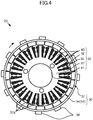
- FIG. 4 is a cross-sectional view of the permanent magnet type motor 20 shown in FIG. 2 , as sectioned perpendicular to its rotation axis line.
- the rotor 30 includes a permanent magnet part 37.
- the rotor 30 includes a plurality of magnetic pole portions 37a.
- the plurality of magnetic pole portions 37a are formed by the permanent magnet part 37.
- the plurality of magnetic pole portions 37a are provided on an inner circumferential surface of the back yoke portion 34.
- the permanent magnet part 37 includes a plurality of permanent magnets. That is, the rotor 30 includes a plurality of permanent magnets.
- the plurality of magnetic pole portions 37a are provided in the plurality of permanent magnets, respectively.
- the permanent magnet part 37 may alternatively be configured as a single annular permanent magnet.
- the single permanent magnet is magnetized such that the plurality of magnetic pole portions 37a appear side by side on the inner circumferential surface.
- the number of magnetic pole portions 37a included in the rotor 30 is more than the number of teeth 43.
- the number of magnetic pole portions is equal to 4/3 of the number of slots.
- the stator winding W is wound around each of the teeth 43. That is, the multi-phase stator windings W are arranged through the slots SL. In the state shown in FIG. 4 , the stator windings W are in the slots SL.
- Each of the multi-phase stator windings W belongs to any of U-phase, V-phase, and W-phase.
- the stator windings W are arranged in the order of U-phase, V-phase, and W-phase, for example.
- the rotor 30 includes, on its outer surface, a plurality of detection object parts 38 for detection of the rotation position of the rotor 30. Magnetic effects are used to detect the plurality of detection object parts 38.
- the plurality of detection object parts 38 arranged at intervals with respect to the circumferential direction are provided on the outer surface of the rotor 30.
- the detection object parts 38 are made of a ferromagnetic material.
- the combustion control unit 63 controls the spark plug 19 and the fuel injector device 18, to control the combustion operation of the single-cylinder engine 10.
- the combustion control unit 63 controls the spark plug 19 and the fuel injector device 18, to control the rotational force of the single-cylinder engine 10.
- the combustion control unit 63 controls the spark plug 19 and the fuel injector device 18 in accordance with the degree of opening of the throttle valve SV which is represented by an output signal of the throttle position sensor 80.
- the control device 60 determines that the condition regarding the amount of operation on the acceleration command part 8 is satisfied.
- step S19 the control device 60 determines whether or not an assistance termination condition regarding the piston operation is fulfilled. If the assistance termination condition is fulfilled (S19:Yes), the control device 60 terminates the assistance to the piston operation. If the assistance termination condition is not fulfilled (S19:No), the control device 60 continues the assistance to the piston operation (S18).
- the increased amount of mixed gas is combusted, so that the rotation speed of the crankshaft 15 significantly increases.
- the single-cylinder engine 10 is able to, after the rotation speed of the crankshaft 15 once rises, compress and combust an increased amount of air in a stable manner. As a result, power generated by the combustion operation which is a function inherent in the engine is increased like a chain reaction. The rotation speed of the crankshaft 15 rapidly increases accordingly.
Landscapes
- Engineering & Computer Science (AREA)
- Chemical & Material Sciences (AREA)
- Combustion & Propulsion (AREA)
- Mechanical Engineering (AREA)
- General Engineering & Computer Science (AREA)
- Power Engineering (AREA)
- Control Of Vehicle Engines Or Engines For Specific Uses (AREA)
- Control Of Throttle Valves Provided In The Intake System Or In The Exhaust System (AREA)
- Electrical Control Of Air Or Fuel Supplied To Internal-Combustion Engine (AREA)
Abstract
Description
- The present teaching relates to a straddled vehicle and to method for controlling a straddled vehicle.
- In a straddled vehicle as typified by a motorcycle, for example, improvement in acceleration performance which is basic performance is desired.
- For example,
JP 5874315 JP 5874315 JP 5874315 - The control device of the straddled vehicle shown in
JP 5874315 - An object of the present teaching is to provide a straddled vehicle to method for controlling a straddled vehicle with its acceleration performance improved by exerting engine performance.
- According to the present invention said object is solved by a straddled vehicle having the features of
independent claim 1. Moreover, said object is solved by method for controlling a straddled vehicle having the features ofindependent claim 7. Preferred embodiments are laid down in the dependent claims. - It has been conducted studies on acceleration performance of a straddled vehicle. It has been conducted studies particularly on improving acceleration performance by increasing engine performance.
- One of conceivable means for increasing engine performance in view of acceleration performance of a straddled vehicle is to reduce the inertia of a movable mechanism included in the engine, and more specifically to reduce the inertia of rotation of a crankshaft. The inertia of rotation of the crankshaft includes not only the turning moment of the crankshaft itself but also the inertia of a piston, a connecting rod, a flywheel, and the like, which move in conjunction with the crankshaft. For example, reducing the weight of the piston leads to reducing the inertia of rotation of the crankshaft. For example, reducing the moment of inertia of the flywheel leads to reducing the inertia of rotation of the crankshaft.
- Reduction in the inertia of rotation of the crankshaft makes it easy that the rotation speed of the crankshaft is increased by a force generated by combustion. As a result, when, for example, acceleration of the straddled vehicle is requested by a rider's operation, the rotation of the crankshaft can be steeply accelerated following the operation. Thus, the acceleration performance is improved.
- It, however, has been found that seeking to reduce the inertia of rotation of the crankshaft may rather deteriorate the acceleration performance in some cases. It has been studied occurrence of deterioration in the acceleration performance in a case where, for example, a mixed gas containing air and a fuel is supplied to a combustion chamber. This has resulted in a discovery that the performance of accelerating rotation of the crankshaft of the engine deteriorates when, for example, a state where a relatively small amount of mixed gas is supplied to the combustion chamber in an intake stroke continues before an acceleration operation and then the amount of mixed gas supply is rapidly increased by the acceleration operation. It has been conducted further studies on causes for the deterioration in the performance of accelerating rotation of the crankshaft.
- When the amount of mixed gas supplied to the combustion chamber in the intake stroke before the acceleration operation is relatively small, a force generated by combustion is weak. This leads to a low rotation speed of the crankshaft. As a result, the crankshaft has a low rotational energy. The rotational energy of the crankshaft is further lowered when, for example, the inertia of rotation of the crankshaft is low. The crankshaft and the piston move in conjunction with each other. A low rotational energy of the crankshaft means a low kinetic energy of the piston, and in more detail, means that a low kinetic energy is available for operating the piston.
- If the amount of mixed gas supplied to the combustion chamber in the intake stroke is rapidly increased by the acceleration operation, the piston compresses the increased amount of mixed gas with the low kinetic energy and therefore the rotation speed is likely to drop. When, for example, the inertia of the crankshaft is low, a significant drop in the rotation speed occurs at a time of compression. Particularly in a single-cylinder engine, a combustion stroke less frequently comes in every rotation of the crankshaft. This makes it likely that the rotation speed of the crankshaft largely varies. As a result, a significant drop in the rotation speed occurs due to a compression reaction force generated by the increased amount of mixed gas. The drop in the rotation speed tends to retard an entire combustion operation of the single-cylinder engine. It therefore takes time for the rotation speed of the crankshaft to rise thereafter. That is, the performance of accelerating rotation of the crankshaft deteriorates. The acceleration performance of the straddled vehicle deteriorates accordingly.
- It has been conceived of promptly assisting the piston operation with a motor at a time when the amount of mixed gas supplied in the intake stroke increases. Promptly assisting the piston operation at a time when the amount of mixed gas increases helps the piston compress the increased amount of mixed gas.
- If assistance to the piston operation via rotation of the crankshaft is started before the piston compresses the mixed gas, not limited to a time period during which the piston compresses the mixed gas; a high operation speed of the piston is ensured at a time point when the compression of the mixed gas is started. A high operation speed of the piston and a high rotation speed of the crankshaft enable the piston to compress the mixed gas with a high kinetic energy even when, for example, the inertia is low.
- In particular, a single-cylinder engine has a high-load region in which a high load is put on the piston operation for compressing the mixed gas, and a low-load region in which a load put thereon is lower than that of the high-load region. From the viewpoint of the rotation angle of the crankshaft, the low-load region of the single-cylinder engine is wider than the high-load region thereof. Therefore, a time period in which the piston operation is assisted is not limited to the time period during which the mixed gas is compressed, but can easily be ensured before the time period during which the mixed gas is compressed. This helps the kinetic energy be increased at a time point when the piston compresses the mixed gas.
- It has been discovered that how promptly the piston operation is assisted after an increase in the amount of mixed gas is important in improving the acceleration performance. It has been conducted further studies, to reach an idea that starting to assist the piston operation promptly after an increase in the amount of mixed gas is enabled by making the motor's assist operation triggered by the logical OR of a plurality of conditions regarding an increase in the amount of mixed gas. For example, it is conceivable to adopt, as a trigger of the assist operation, the logical OR of a condition regarding the amount of operation on an acceleration command part that instructs to what degree a throttle valve is to be opened and a condition regarding the change rate of the amount of operation on the acceleration command part. In such a case, for example, even though the condition regarding the amount of operation on the acceleration command part is not yet satisfied, the assistance to the piston operation can be started immediately after the condition regarding the change rate is satisfied. This enables the piston to compress the increased amount of mixed gas with a high kinetic energy.
- Enabling the piston to complete the compression of the increased amount of mixed gas without any delay results in generation of increased power in subsequent combustion of the increased amount of mixed gas. As a consequence, a kinetic energy subsequently available for the piston is increased. This causes a chain reaction of increasing power generated by combustion of an increased amount of mixed gas and enabling the piston having the increased power to compress the increased amount of mixed gas. In this manner, power outputted from the single-cylinder engine is rapidly increased by a combustion function that is inherent in the single-cylinder engine.
- On the other hand, for example, the control device of the straddled vehicle shown in
JP 5874315 JP 5874315 - The present teaching assists the piston operation as promptly as possible after the amount of mixed gas is increased, thus promptly exerting the combustion function that is inherent in the engine. As a result, the acceleration performance is improved by the performance of the engine which is able to output higher power than the motor is.
- The present teaching is a teaching accomplished based on the findings described above.
- To solve the problems described above, the present teaching adopts the following configurations.
- (1) A straddled vehicle including:
- a single-cylinder engine including a piston and a crankshaft, the piston provided in a cylinder and moved to and fro by combustion of a mixed gas containing air and a fuel, the crankshaft configured to be rotated along with the to-and-fro movement of the piston;
- a drive wheel configured to receive a rotational force outputted from the single-cylinder engine via the crankshaft and drive the straddled vehicle;
- an acceleration command part that instructs that the straddled vehicle be accelerated in accordance with an operation thereon;
- a throttle valve arranged in an intake passage connecting with the single-cylinder engine, and configured to be opened to a degree that is based on the amount of operation on the acceleration command part so that an amount of the air is supplied to the single-cylinder engine, the amount corresponding to the degree of opening;
- a permanent magnet type motor including a rotor and a permanent magnet, the rotor connected directly or indirectly to the crankshaft so as to be rotatable in response to rotation of the crankshaft, the permanent magnet provided to the rotor;
- a battery;
- an inverter including a plurality of switching parts by which a current flowing between the battery and the permanent magnet type motor is controlled; and
- a control device that controls the plurality of switching parts so as to assist a piston operation by directing the permanent magnet type motor to apply a force to the piston via the crankshaft such that the force cooperates with a force generated by combustion in the single-cylinder engine to move the piston to and fro, the control triggered by the amount of operation on the acceleration command part being increased so as to satisfy at least one of a condition regarding the amount of operation on the acceleration command part and a condition regarding the rate of increase in the amount of operation on the acceleration command part under a state where the throttle valve is not in a full-open state and the piston is moved to and fro by combustion of the mixed gas.
The rotor of the permanent magnet type motor is connected to the crankshaft. The rotor is provided with the permanent magnet. The plurality of switching parts arranged between the permanent magnet type motor and the battery control the current flowing between the battery and the permanent magnet type motor. The switching parts are controlled by the control device. The control device is able to control a force to be supplied from the permanent magnet type motor to the piston via the crankshaft.
When sharp acceleration of the straddled vehicle is needed, the acceleration command part is operated quickly, so that the throttle valve is opened quickly, which increases the amount of mixed gas to be supplied to the single-cylinder engine. Before the increase in the amount of supplied mixed gas, the amount of mixed gas is relatively small, and therefore the rotation speed of the crankshaft is low. That is, a kinetic energy available for the piston operation is low. The quick open of the throttle valve causes a rapid increase in the amount of air supplied to the single-cylinder engine in an intake stroke. The increase in the amount of compressed air acts in such a direction that the piston operation is more retarded.
The control device of the straddled vehicle of (1) controls the plurality of switching parts, triggered by the amount of operation on the acceleration command part being increased so as to satisfy at least one of a condition regarding the amount of operation on the acceleration command part and a condition regarding the rate of increase in the amount of operation on the acceleration command part. The control device controls the switching parts so as to assist the piston operation. In the assistance to the piston operation, the permanent magnet type motor applies a force to the piston such that the force cooperates with a force generated by combustion in the single-cylinder engine to move the piston to and fro.
As a condition for starting to assist the piston operation, the control device adopts the logical OR of the condition regarding the amount of operation on the acceleration command part and the condition regarding the rate of increase in the amount of operation on the acceleration command part. This enables the permanent magnet type motor to promptly assist the piston operation. For example, even though the condition regarding the amount of operation on the acceleration command part is not yet satisfied, the permanent magnet type motor is able to start to assist the piston operation immediately after the condition regarding the rate of increase in the amount of operation on the acceleration command part is satisfied.
For example, the control device can regard a rapid increase in the amount of operation on the acceleration command part as a rapid increase in the amount of air supply, and promptly start to assist the piston operation. It may be acceptable that the assistance to the piston operation is started before the piston compresses the increased amount of air. In the single-cylinder engine, a low-load region is wider than a high-load region in which a load on operations of the piston and the crankshaft increases along with air compression. In the single-cylinder engine, the assistance to the piston operation is more likely to be started in the low-load region which is wider. In such a case, a force that the permanent magnet type motor applies before the piston compresses air is accumulated as energy for operating the piston. Upon immediate start of the assistance to the piston operation as triggered by a quick increase in the amount of operation on the acceleration command part, a strong force applied by the permanent magnet type motor cooperates with a force generated by combustion to enable the piston to compress the increased amount of air.
As described above, while the amount of mixed gas supplied to the single-cylinder engine is increasing, the permanent magnet type motor promptly assists the piston operation, thus suppressing a drop in the piston operation speed at a time of compressing an increased amount of mixed gas.
The increased amount of mixed gas is combusted after compression is performed by the piston having received application of the force from the permanent magnet type motor. This allows an increased force to be generated by the combustion. That is, the rotational force generated by a combustion function that is inherent in the engine is increased. Thus, the rotation of the crankshaft is accelerated by combustion power generated in the engine. After the rotation of the crankshaft is accelerated by combustion power, the rotation speed of the crankshaft is stabilized even though an increased amount of mixed gas is supplied.
In the straddled vehicle of (1), as thus far described, the assistance to the piston operation is promptly performed in response to an increase in the amount of air supplied to the single-cylinder engine, so that the combustion function of the single-cylinder engine is promptly exerted in response to an increase in the amount of air supply. In this manner, the combustion operation of the single-cylinder engine obtains improved performance of accelerating rotation of the crankshaft. Accordingly, the straddled vehicle has high acceleration performance.
Even when, for example, the single-cylinder engine is so designed as to reduce the inertia of rotation of the crankshaft, a drop in the rotation speed of the crankshaft which may be caused by an increase in the amount of air supply is suppressed. A reduced inertia of rotation of the crankshaft leads to a further increase in the performance of accelerating the rotation speed of the crankshaft. Accordingly, the straddled vehicle has high acceleration performance. This is how the straddled vehicle of (1) improves acceleration performance by exerting engine performance better.
The present teaching is applicable to an engine in which the inertia of rotation of a crankshaft is not reduced, for example. The present teaching is also applicable to an engine in which the inertia of rotation of a crankshaft is reduced, for example. - (2) The straddled vehicle of (1), in which
the control device controls the plurality of switching parts so as to assist the piston operation, triggered by the amount of operation on the acceleration command part being increased so as to satisfy the at least one condition irrespective of how long a state of the increase in the amount of operation on the acceleration command part continues.
In the configuration of (2), the control device performs such a control that the permanent magnet type motor applies a force to the piston so as to move the piston to and fro, irrespective of how long a state of the increase in the amount of operation on the acceleration command part continues. Therefore, if at least one of a condition regarding the amount of operation on the acceleration command part and a condition regarding the rate of increase in the amount of operation on the acceleration command part is satisfied, the permanent magnet type motor applies a force to the piston so as to move the piston to and fro without waiting until the state where the amount of operation on the acceleration command part is increased continues. This means that the permanent magnet type motor promptly assists the piston operation in response to an increase in the amount of air supplied to the single-cylinder engine. The acceleration performance is improved by better exertion of the engine performance. - (3) The straddled vehicle of (1), including a throttle position sensor that detects the degree of opening of the throttle valve, in which
the control device makes determination about the rate of increase in the amount of operation on the acceleration command part and the amount of operation on the acceleration command part based on a result of detection performed by the throttle position sensor, and controls the plurality of switching parts so as to assist the piston operation, the control triggered by the amount of operation on the acceleration command part being increased so as to satisfy at least one of a condition regarding the amount of operation on the acceleration command part and a condition regarding the rate of increase in the amount of operation on the acceleration command part.
In the configuration of (3), determination about a condition regarding the rate of increase in the amount of operation on the acceleration command part and a condition regarding the amount of operation on the acceleration command part is made based directly on the degree of opening of the throttle valve. This enables the state of the throttle valve to be precisely reflected by the control of assisting the piston operation. Accordingly, the piston operation can be assisted more promptly in response to an increase in the amount of air. The acceleration performance is further improved by better exertion of the engine performance. - (4) The straddled vehicle of any one of (1) to (3), further including a clutch that switches between states of allowing and blocking transmission of a rotational force from the crankshaft to the drive wheel in accordance with the rotation speed of the crankshaft, in which
in at least part of a time period during which the clutch blocks transmission of the rotational force, the control device controls the switching parts so as to assist the piston operation, triggered by the amount of operation on the acceleration command part being increased so as to satisfy at least one of a condition regarding the amount of operation on the acceleration command part and a condition regarding the rate of increase in the amount of operation on the acceleration command part.
In the state where the clutch allows transmission of the rotational force, for example, the inertia of the drive wheel is reflected by the inertia of rotation of the crankshaft. While the clutch blocks transmission of the rotational force, on the other hand, the inertia of rotation of the crankshaft is relatively low. In this state, the piston has a low energy for compressing air. In the configuration of (4), the permanent magnet type motor assists the piston operation, triggered by the amount of operation on the acceleration command part being increased so as to satisfy at least one of a condition regarding the amount of operation on the acceleration command part and a condition regarding the rate of increase in the amount of operation on the acceleration command part. This improves the rotation acceleration performance using the rotational force generated by engine combustion when the clutch is in the blocking state so that the inertia of rotation of the crankshaft is low. - (5) The straddled vehicle of any one of (1) to (4), in which
in a case where the rotation speed of the crankshaft is equal to or less than an idling rotation speed of the single-cylinder engine, the control device controls the plurality of switching parts so as to assist the piston operation, triggered by the amount of operation on the acceleration command part being increased so as to satisfy at least one of a condition regarding the amount of operation on the acceleration command part and a condition regarding the rate of increase in the amount of operation on the acceleration command part.
When the rotation speed of the crankshaft is equal to or less than the idling rotation speed of the single-cylinder engine, a smaller amount of air is supplied to the single-cylinder engine as compared with, for example, when the rotation speed of the crankshaft is equal to or more than the idling rotation speed. As a consequence, a weaker force is applied to the piston by combustion in the single-cylinder engine. That is, the piston has a low energy for compressing the mixed gas. In the configuration of (5), in an idling state where the piston has a low energy, the permanent magnet type motor assists the piston operation, triggered by the acceleration command part being displaced so as to satisfy at least one of a condition regarding the amount of operation on the acceleration command part and a condition regarding the rate of increase in the amount of operation on the acceleration command part. This improves the rotation acceleration performance using the rotational force generated by engine combustion when the clutch is in the blocking state, even though the piston has a low energy. - (6) The straddled vehicle of any one of (1) to (5), in which
the throttle valve is a mechanical throttle valve mechanically coupled to the acceleration command part with a cable, and
the control device controls the plurality of switching parts so as to assist the piston operation, triggered by the amount of operation on the acceleration command part, which is mechanically coupled to the mechanical throttle valve, being increased so as to satisfy at least one of a condition regarding the amount of operation on the acceleration command part and a condition regarding the rate of increase in the amount of operation on the acceleration command part. - Unlike an electronic-controlled throttle for example, a mechanical throttle valve mechanically coupled to the acceleration command part with a cable has the degree of its opening directly reflecting an operation on the acceleration command part. For example, when a rider suddenly operates the acceleration command part, the mechanical throttle valve is opened at a high speed. In such a situation as well, the configuration of (6) allows the permanent magnet type motor to promptly assist the piston operation. Accordingly, the performance of accelerating the rotation speed of the crankshaft can be improved, also in a straddled vehicle including a mechanical throttle valve.
- The straddled vehicle of the present teaching includes a drive wheel. Examples of the straddled vehicle of the present teaching include motorcycles, motor tricycles, and ATVs (All-Terrain Vehicles).
- The engine of the present teaching includes a piston and a crankshaft. Examples of the crankshaft of the present teaching include a crankshaft coupled to the piston with the connecting rod, and a crankshaft coupled to the piston with another member in addition to the connecting rod. The crankshaft is configured such that, for example, to-and-fro movement of the piston is converted into rotational motion which is then transmitted to the crankshaft.
- The engine of the present teaching includes, for example, a cylinder, a piston, and a connecting rod, the piston arranged in the cylinder such that the piston is freely movable to and fro, the connecting rod coupled to the piston and the crankshaft. Examples of the engine of the present teaching include a four-stroke engine and a two-stroke engine.
- Examples of the throttle valve of the present teaching include a mechanical throttle valve and an electronic-controlled throttle valve. The mechanical throttle valve is connected to the acceleration command part with a wire that mechanically transmits displacement of the acceleration command part. The electronic-controlled throttle valve is connected to an actuator that is operated in accordance with an electrical signal indicating displacement of the acceleration command part. In a straddled vehicle including the electronic-controlled throttle valve, such a control is possible that, for example, the throttle valve is operated slowly relative to the speed in which the acceleration command part is operated. In the configuration of the present teaching, however, a drop in the rotation speed of the crankshaft is suppressed, even after the amount of mixed gas is increased. This enables the throttle valve to be operated quickly. As a result, further improvement in the acceleration performance is achieved.
- The engine of the present teaching moves the piston to and fro by combusting a mixed gas containing air and a fuel. The engine of the present teaching includes engines of direct injection type and engines of intake manifold injection type.
- The permanent magnet type motor of the present teaching is a motor including a permanent magnet. The permanent magnet type motor of the present teaching includes a stator and a rotor. The rotor of the permanent magnet type motor of the present teaching includes a permanent magnet. The rotor of the permanent magnet type motor of the present teaching includes no winding. The stator of the permanent magnet type motor of the present teaching includes windings. The permanent magnet type motor of the present teaching includes windings corresponding to a plurality of phases. The permanent magnet type motor of the present teaching may include windings corresponding to two phases, four phases, or more, for example. The permanent magnet type motor of the present teaching, however, is able to easily perform a vector control and a phase control when provided with windings corresponding to three phases, for example. The windings of the stator are wound on a stator core. The rotor is rotated with the permanent magnet facing the stator core with an air gap therebetween. The permanent magnet type motor of the present teaching includes a motor of radial gap type and a motor of axial gap type. The motor of radial gap type, which is the permanent magnet type motor of the present teaching, includes a motor of outer rotor type and a motor of inner rotor type, the motor of outer rotor type provided with a rotor that rotates outside a stator, the motor of inner rotor type provided with a rotor that rotates inside a stator. The permanent magnet type motor of the present teaching may generate power, for example. The permanent magnet type motor of the present teaching includes a permanent magnet type motor having a function as a generator and a permanent magnet type motor not having a function as a generator.
- In the present teaching, the rotor of the permanent magnet type motor includes a rotor connected directly to the crankshaft, a rotor connected indirectly to the crankshaft with interposition of a transmission mechanism, and the like. Examples of the transmission mechanism include belts, chains, gears, speed reducers, speed increasers, and the like. The rotor of the present teaching is preferably connected to the crankshaft with its speed ratio fixed relative to the crankshaft.
- The inverter of the present teaching includes the plurality of switching parts by which a current outputted from the battery to the permanent magnet type motor is controlled. The switching parts are transistors, for example. The switching parts include FETs (Field Effect Transistors), thyristors, and IGBTs (Insulated Gate Bipolar Transistors), for example. The inverter includes a bridge inverter composed of a plurality of switching parts, for example.
- The control device of the present teaching includes a control device configured to control operations of the engine, for example. The control device of the present teaching, however, also includes a control device different from a device configured to control operations of the engine, for example.
- The acceleration command part of the present teaching is means for instructing that the straddled vehicle be accelerated. In other words, the acceleration command part of the present teaching is means for indicating the amount of increase in an engine torque. In other words, the acceleration command part of the present teaching is means for instructing that the degree of opening of the throttle valve be increased. The acceleration command part of the present teaching is, for example, operated by a rider. The acceleration command part of the present teaching is, for example, an accelerator grip. In this case, the rotational position of the accelerator grip represents the amount of operation on the acceleration command part. The acceleration command part includes, for example, a pedal, a lever, and a switch.
- The acceleration command part also includes, for example, a device that is not displaceable by an operation. Examples of such an acceleration command part include an acceleration command part configured such that a force applied to the acceleration command part represents the amount of operation on the acceleration command part. The acceleration command part may be configured to instruct not only that the straddled vehicle be accelerated but also that the straddled vehicle be decelerated. In such a case, the amount of operation on the acceleration command part performed to accelerate the straddled vehicle corresponds to "the amount of operation on the acceleration command part".
- The acceleration command part is configured such that the greater the amount of operation on the acceleration command part is, the greater the amount of increase in the speed of the straddled vehicle instructed by the acceleration command part is. In other words, the acceleration command part is configured such that the greater the amount of operation on the acceleration command part is, the higher an engine torque instructed by the acceleration command part is. In other words, the acceleration command part is configured such that the greater the amount of operation on the acceleration command part is, the greater the amount of increase in the degree of opening of the throttle valve instructed by the acceleration command part is. The acceleration command part is configured such that the higher the rate of increase in the amount of operation on the acceleration command part is, the larger the degree of acceleration of the straddled vehicle (the speed at which the degree of opening of the throttle valve increases) instructed by the acceleration command part is.
- The control device of the present teaching may, for example, use a result of detection performed by a throttle position sensor that is connected to the throttle valve, for the determination about the rate of increase in the amount of operation on the acceleration command part and the amount of operation on the acceleration command part.
- The control device may, for example, use a result of detection performed by a sensor that is connected to the acceleration command part, for the determination about the rate of increase in the amount of operation on the acceleration command part and the amount of operation on the acceleration command part. In a configuration including an electronic-controlled throttle valve, for example, a delay of operation of the throttle valve may occur relative to displacement of the acceleration command part. In such a case, a piston assistance operation is started based on a result of detection performed by the sensor that is connected to the acceleration command part, thus enabling more prompt start of the piston assistance operation.
- In the present teaching, the condition regarding the amount of operation on the acceleration command part may be, for example, that the amount of operation on the acceleration command part exceed a certain fixed operation amount limit. The condition regarding the amount of operation may be, for example, that the amount of operation on the acceleration command part exceed a prescribed amount relative to the amount of operation performed a specified time before. The condition regarding the rate of increase in the amount of operation on the acceleration command part may be, for example, whether or not the rate of increase in the amount of operation on the acceleration command part is equal to or higher than a fixed speed limit. The condition regarding the rate may be, for example, that the rate of increase in the amount of operation on the acceleration command part be equal to or higher than a speed limit specified in accordance with the amount of operation on the acceleration command part. In the present teaching, an increase in the amount of operation on the acceleration command part causes an increase in the degree of opening of the throttle valve.
- Configuring the control device of the present teaching to perform the piston assistance operation triggered by the acceleration command part being displaced so as to satisfy at least one of a condition regarding the amount of operation on the acceleration command part and a condition regarding the rate of increase in the amount of operation on the acceleration command part, means performing the piston assistance operation upon fulfillment of either one of the conditions, without waiting for fulfillment of the other of the conditions.
- While the permanent magnet type motor assists the piston operation, the single-cylinder engine is in combustion operation. Application of a force to the piston for causing to-and-fro movement thereof by the permanent magnet type motor is, for example, application of a force to the piston for causing to-and-fro movement thereof by the permanent magnet type motor driving the crankshaft.
- The control device of the present teaching may be configured to, for example, control the switching parts so as to assist the piston operation in at least part of a time period during which the clutch blocks transmission of the rotational force. The control device may be configured to, for example, control the switching parts so as to assist the piston operation in a time period during which the clutch allows transmission of the rotational force.
- The control device of the present teaching may be configured to, triggered by the amount of operation on the acceleration command part being increased so as to satisfy the one condition, control the plurality of switching parts so as to assist the piston operation, in a case where the rotation speed of the crankshaft is more than the idling rotation speed of the single-cylinder engine.
- The present teaching is able to improve acceleration performance by exerting engine performance.
-
- [
FIG. 1] FIG. 1 shows an external appearance of a straddled vehicle according to an embodiment of the present teaching. - [
FIG. 2] FIG. 2 is a partial cross-sectional view schematically showing an outline configuration of an engine unit shown inFIG. 1 . - [
FIG. 3] FIG. 3 is an illustrative diagram schematically showing the relationship between a crank angle position and a required torque of a single-cylinder engine. - [
FIG. 4] FIG. 4 is a cross-sectional view of a permanent magnet type motor shown inFIG. 2 , as sectioned perpendicular to its rotation axis line. - [
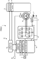
FIG. 5] FIG. 5 is a block diagram outlining an electrical configuration of the straddled vehicle shown inFIG. 1 . - [
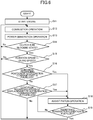
FIG. 6] FIG. 6 is a flowchart illustrating operations of the straddled vehicle. - [
FIG. 7] FIG. 7 is a timing chart showing an operation on an acceleration command part and a change in the crank rotation speed. - [
FIG. 8] FIG. 8 is a timing chart showing an operation on the acceleration command part and a change in the crank rotation speed under an operation condition different from that ofFIG. 7 . - Hereunder, the present teaching is described based on preferred embodiments with reference to the drawings.
-
FIG. 1 shows an external appearance of a straddled vehicle according to an embodiment of the present teaching. - A straddled
vehicle 1 shown inFIG. 1 includes avehicle body 2 andwheels vehicle 1 is, to be specific, a motorcycle. - The straddled
vehicle 1 includes an engine unit EU. The engine unit EU includes a single-cylinder engine 10 (seeFIG. 2 ). - The
rear wheel 3b is a drive wheel. Thewheel 3b receives a rotational force outputted from the single-cylinder engine 10, to drive the straddledvehicle 1. - The straddled
vehicle 1 includes amain switch 5. Themain switch 5 is a switch for supplying power to each part of the straddledvehicle 1. The straddledvehicle 1 includes astarter switch 6. Thestarter switch 6 is a switch for starting the single-cylinder engine 10. The straddledvehicle 1 includes anacceleration command part 8. Theacceleration command part 8 is an operation element for instructing the straddledvehicle 1 be accelerated in accordance with an operation thereon. Theacceleration command part 8 is displaced in accordance with an operation thereon. Theacceleration command part 8 is, to be specific, an accelerator grip. Theacceleration command part 8 is rotated in accordance with an operation thereon. - The straddled
vehicle 1 includes abattery 4. The straddledvehicle 1 includes acontrol device 60 that controls each part of the straddledvehicle 1. -
FIG. 2 is a partial cross-sectional view schematically showing an outline configuration of the engine unit EU shown inFIG. 1 . - The engine unit EU includes the single-
cylinder engine 10 and a permanentmagnet type motor 20. - The single-
cylinder engine 10 includes a crankcase 11, acylinder 12, apiston 13, a connectingrod 14, and acrankshaft 15. Thepiston 13 is arranged in thecylinder 12 such that thepiston 13 is freely movable to and fro. - The
crankshaft 15 is rotatably arranged in thecrank case 11. Thecrankshaft 15 is coupled to thepiston 13 with the connectingrod 14. Acylinder head 16 is attached to an upper portion of thecylinder 12. Thecylinder 12, thecylinder head 16, and thepiston 13 define a combustion chamber. Thecrankshaft 15 is supported on thecrank case 11 via a pair ofbearings 17 in a freely rotatable manner. The permanentmagnet type motor 20 is attached to oneend portion 15a of thecrankshaft 15. A transmission CVT is attached to theother end portion 15b of thecrankshaft 15. The transmission CVT is configured to change the gear ratio which is the ratio of an output rotation speed to an input rotation speed. The transmission CVT is configured to change the gear ratio corresponding to the rotation speed of the wheel relative to the rotation speed of thecrankshaft 15. - The straddled
vehicle 1 includes a clutch CL (seeFIG. 1 ). The clutch CL is connected to the transmission CVT. The clutch CL is a centrifugal clutch. The clutch CL switches between states of allowing and blocking transmission of a rotational force from thecrankshaft 15 to thewheel 3b which serves as a drive wheel. The clutch CL switches between the states of allowing and blocking transmission in accordance with the rotation speed of thecrankshaft 15. When the rotation speed of thecrankshaft 15 is less than a predetermined threshold, the clutch CL is in a blocking state. When the rotation speed of thecrankshaft 15 is more than a predetermined threshold, the clutch CL is in a transmitting state. The predetermined threshold referred to herein may not always need to be a single fixed value in a strict sense. The predetermined threshold may be a value variable depending on running conditions, environmental conditions such as ambient temperature, and the like. The blocking state means a state in which transmission of a rotational force from the crankshaft to the drive wheel is not performed at all. The transmitting state means a state in which transmission of a rotational force from the crankshaft to the drive wheel is performed, including a state in which transmission of a partial rotational force is performed. - The engine unit EU is provided with a throttle valve SV and a
fuel injector device 18. The throttle valve SV is arranged in an intake passage Ip that connects with the single-cylinder engine 10. The throttle valve SV is opened to a degree that is based on the amount of operation on the acceleration command part 8 (seeFIG. 1 ). The throttle valve SV is a mechanical throttle valve. The throttle valve SV is mechanically coupled to theacceleration command part 8 with a cable (not shown). The throttle valve SV is opened in conjunction with an operation received by theacceleration command part 8. The throttle valve SV is opened to a degree that is according to the amount of operation on theacceleration command part 8. The throttle valve SV is opened to a degree that is according to the position of theacceleration command part 8. - The throttle valve SV supplies an amount of air to the single-
cylinder engine 10, the amount corresponding to the degree of opening of the throttle valve SV. The throttle valve SV adjusts the amount of air to be supplied to the single-cylinder engine 10, by adjusting the amount of air flowing in accordance with the degree of opening of the throttle valve SV. - The throttle valve SV is provided with a
throttle position sensor 80 that detects the degree of opening of throttle valve SV. Thethrottle position sensor 80 outputs a signal to thecontrol device 60, the signal indicating the degree of opening of the throttle valve SV. Thefuel injector device 18 injects a fuel, to supply the fuel to the combustion chamber. Thefuel injector device 18 injects the fuel to air flowing in from the throttle valve SV and passing through the intake passage. A mixed gas containing the air and the fuel is supplied to the combustion chamber of the single-cylinder engine 10. - The single-
cylinder engine 10 is also provided with aspark plug 19. - The single-
cylinder engine 10 is an internal combustion engine. The single-cylinder engine 10 is supplied with a fuel. The single-cylinder engine 10 outputs a rotational force by performing a combustion operation in which the mixed gas is combusted. That is, the combustion of the mixed gas supplied to the combustion chamber, which contains the fuel, makes thepiston 13 move to and fro. Thecrankshaft 15 is rotated along with the to-and-fro movement of thepiston 13. The rotational force is outputted to the outside of the single-cylinder engine 10 via thecrankshaft 15. Thewheel 3b (seeFIG. 1 ) receives the rotational force outputted from the single-cylinder engine 10 via thecrankshaft 15, to drive the straddledvehicle 1. - The throttle valve SV adjusts the rotational force of the single-
cylinder engine 10 by adjusting the amount of air to be supplied to the combustion chamber. The amount of air to be supplied to the combustion chamber is adjusted in accordance with the degree of opening of the throttle valve SV. The degree of opening of the throttle valve SV is adjusted in accordance with an operation on the acceleration command part 8 (seeFIG. 1 ). - The
fuel injector device 18 adjusts the rotational force outputted from the single-cylinder engine 10 by adjusting the amount of fuel supply. Thefuel injector device 18 is controlled by thecontrol device 60. Thefuel injector device 18 is controlled so as to supply an amount of fuel corresponding to the amount of air supplied to the single-cylinder engine 10. - The single-
cylinder engine 10 outputs the rotational force via thecrankshaft 15. The rotational force of thecrankshaft 15 is transmitted to thewheel 3b via the transmission CVT and a clutch CL (seeFIG. 1 ). The straddledvehicle 1 is driven by thewheel 3b receiving the rotational force from the single-cylinder engine 10 via thecrankshaft 15. -
FIG. 3 is an illustrative diagram schematically showing the relationship between a crank angle position and a required torque of the single-cylinder engine 10.FIG. 3 shows the torque required for rotating thecrankshaft 15 under a state where the single-cylinder engine 10 does not perform the combustion operation. - The single-
cylinder engine 10 is a four-stroke engine. The single-cylinder engine 10 has, during four strokes, a high-load region TH in which a high load is put on rotation of thecrankshaft 15 and a low-load region TL in which a load put on rotation of thecrankshaft 15 is lower than that of the high-load region TH. The high-load region means a region in one combustion cycle of the single-cylinder engine 10 where a load torque is higher than an average value Av of the load torque over the one combustion cycle. From the viewpoint of the rotation angle of thecrankshaft 15, the low-load region TL is equal to or wider than the high-load region TH. To be specific, the low-load region TL is wider than the high-load region TH. In other words, a rotation angle region corresponding to the low-load region TL is wider than a rotation angle region corresponding to the high-load region TH. During rotation, the single-cylinder engine 10 repeats an intake stroke, a compression stroke, a combustion stroke (expansion stroke), and an exhaust stroke. The compression stroke overlaps the high-load region TH. - One combustion cycle of the single-
cylinder engine 10 includes one intake stroke, one compression stroke, one combustion stroke, and one exhaust stroke. - In the intake stroke, an amount of mixed gas is supplied to the combustion chamber, the amount corresponding to the degree of opening of the throttle valve SV. In the compression stroke, the
piston 13 compresses the mixed gas contained in the combustion chamber. In the expansion stroke, the mixed gas ignited by thespark plug 19 is combusted, and pushes thepiston 13. In the exhaust stroke, a gas remaining after the combustion, which is an exhaust gas, is discharged from the combustion chamber. -
FIG. 4 is a cross-sectional view of the permanentmagnet type motor 20 shown inFIG. 2 , as sectioned perpendicular to its rotation axis line. - The permanent
magnet type motor 20 is described with reference toFIGS. 2 and4 . - The permanent
magnet type motor 20 is a three-phase brushless motor of permanent magnet type. The permanentmagnet type motor 20 functions also as a three-phase brushless generator of permanent magnet type. - The permanent
magnet type motor 20 includes arotor 30 and astator 40. The permanentmagnet type motor 20 of this embodiment is of radial gap type. The permanentmagnet type motor 20 is of outer rotor type. That is, therotor 30 is an outer rotor, and thestator 40 is an inner stator. - The
rotor 30 includes arotor body part 31. Therotor body part 31 is made of, for example, a ferromagnetic material. Therotor body part 31 is in the shape of a cylinder with a bottom. Therotor body part 31 includes acylindrical boss portion 32, a disk-shapedbottom wall portion 33, and aback yoke portion 34 having a cylindrical shape. Thebottom wall portion 33 and theback yoke portion 34 are integrally formed. Here, it may also be acceptable that thebottom wall portion 33 and theback yoke portion 34 are formed as separate parts. Thebottom wall portion 33 and theback yoke portion 34 are secured to thecrankshaft 15 via thecylindrical boss portion 32. A winding to which a current is supplied is not provided in therotor 30. - The
rotor 30 includes apermanent magnet part 37. Therotor 30 includes a plurality ofmagnetic pole portions 37a. The plurality ofmagnetic pole portions 37a are formed by thepermanent magnet part 37. The plurality ofmagnetic pole portions 37a are provided on an inner circumferential surface of theback yoke portion 34. In this embodiment, thepermanent magnet part 37 includes a plurality of permanent magnets. That is, therotor 30 includes a plurality of permanent magnets. The plurality ofmagnetic pole portions 37a are provided in the plurality of permanent magnets, respectively. - The
permanent magnet part 37 may alternatively be configured as a single annular permanent magnet. In such a configuration, the single permanent magnet is magnetized such that the plurality ofmagnetic pole portions 37a appear side by side on the inner circumferential surface. - The plurality of
magnetic pole portions 37a are provided such that N pole and S pole appear alternately with respect to a circumferential direction of the permanentmagnet type motor 20. In this embodiment, the number of magnetic poles of therotor 30 opposed to thestator 40 is twenty-four. The number of magnetic poles of therotor 30 means the number of magnetic poles opposed to thestator 40. No magnetic material is arranged between themagnetic pole portions 37a and thestator 40. - The
magnetic pole portions 37a are provided outside thestator 40 with respect to the radial direction of the permanentmagnet type motor 20. Theback yoke portion 34 is provided outside themagnetic pole portions 37a with respect to the radial direction. The number ofmagnetic pole portions 37a included in the permanentmagnet type motor 20 is more than the number ofteeth 43. - The
rotor 30 may be of interior permanent magnet type (IPM type) in which themagnetic pole portions 37a are embedded in a magnetic element, but it preferably is of surface permanent magnet type (SPM type) in which themagnetic pole portions 37a are exposed from a magnetic element as illustrated in this embodiment. - A cooling fan F is provided to the
bottom wall portion 33 of therotor 30. - The
stator 40 includes a stator core ST and a plurality of stator windings W. The stator core ST includes a plurality ofteeth 43 arranged at intervals with respect to the circumferential direction. The plurality ofteeth 43 integrally extend from the stator core ST toward radially outside. In this embodiment, eighteenteeth 43 in total are arranged at intervals with respect to the circumferential direction. In other words, the stator core ST has eighteen slots SL in total that are arranged at intervals with respect to the circumferential direction. Theteeth 43 are arranged at equal intervals with respect to the circumferential direction. - The number of
magnetic pole portions 37a included in therotor 30 is more than the number ofteeth 43. The number of magnetic pole portions is equal to 4/3 of the number of slots. - The stator winding W is wound around each of the
teeth 43. That is, the multi-phase stator windings W are arranged through the slots SL. In the state shown inFIG. 4 , the stator windings W are in the slots SL. Each of the multi-phase stator windings W belongs to any of U-phase, V-phase, and W-phase. The stator windings W are arranged in the order of U-phase, V-phase, and W-phase, for example. - The
rotor 30 includes, on its outer surface, a plurality ofdetection object parts 38 for detection of the rotation position of therotor 30. Magnetic effects are used to detect the plurality ofdetection object parts 38. The plurality ofdetection object parts 38 arranged at intervals with respect to the circumferential direction are provided on the outer surface of therotor 30. Thedetection object parts 38 are made of a ferromagnetic material. - The rotor
position detection device 50 is a device that detects the position of therotor 30. The rotorposition detection device 50 is provided at a position allowed to be opposed to the plurality ofdetection object parts 38. - The
rotor 30 of the permanentmagnet type motor 20 is connected to thecrankshaft 15 such that therotor 30 is rotated along with rotation of thecrankshaft 15. More specifically, therotor 30 of the permanentmagnet type motor 20 is connected to thecrankshaft 15 such that therotor 30 is rotated with its speed ratio fixed relative to thecrankshaft 15. Therotor 30 is directly connected to thecrankshaft 15 of the single-cylinder engine 10. - In this embodiment, the
rotor 30 is attached to thecrankshaft 15 without interposition of a power transmission mechanism (such as a belt, a chain, a gear, a speed reducer, or a speed increaser). Therotor 30 is rotated with a speed ratio of 1:1 relative to thecrankshaft 15. The permanentmagnet type motor 20 is configured such that therotor 30 is driven in forward rotation at a time of combustion operation of the single-cylinder engine 10. - The rotation axis line of the permanent
magnet type motor 20 is substantially coincident with the rotation axis line of thecrankshaft 15. - At a time of engine start, the permanent
magnet type motor 20 drives thecrankshaft 15 in forward rotation to start the single-cylinder engine 10. At a time of combustion operation of the single-cylinder engine 10, the permanentmagnet type motor 20 is driven by the single-cylinder engine 10 to generate power. That is, the permanentmagnet type motor 20 has both the function for driving thecrankshaft 15 in forward rotation to start the single-cylinder engine 10 and the function for being driven by the single-cylinder engine 10 to generate power at a time of combustion operation of the single-cylinder engine 10. During at least part of a time period following the start of the single-cylinder engine 10, the permanentmagnet type motor 20 is driven in forward rotation by thecrankshaft 15 to function as a generator. -
FIG. 5 is a block diagram outlining an electrical configuration of the straddledvehicle 1 shown inFIG. 1 . - The straddled
vehicle 1 includes aninverter 61. Thecontrol device 60 controls components of the straddledvehicle 1 including theinverter 61. - The permanent
magnet type motor 20 and thebattery 4 are connected to theinverter 61. When the permanentmagnet type motor 20 operates as a motor, thebattery 4 supplies power to the permanentmagnet type motor 20. Thebattery 4 is charged with power generated by the permanentmagnet type motor 20. - The
battery 4 is connected to theinverter 61 and a power consuming apparatus via themain switch 5. The power consuming apparatus is an apparatus that consumes power when operating. The power consuming apparatus includes a headlight 7 (seeFIG. 1 ), for example. - The
inverter 61 includes a plurality of switchingparts 611 to 616. In this embodiment, theinverter 61 includes six switchingparts 611 to 616. - The switching
parts 611 to 616 constitute a three-phase bridge inverter. The plurality of switchingparts 611 to 616 are connected to the respective phases of the multi-phase stator windings W. More specifically, among the plurality of switchingparts 611 to 616, every two switching parts that are connected in series constitute a half bridge. The half bridge corresponding to each phase is connected in parallel with thebattery 4. Ones of the switchingparts 611 to 616 constituting the half bridge of each phase are connected to the corresponding phase of the multi-phase stator windings W. - The switching
parts 611 to 616 control a current flowing between thebattery 4 and the permanentmagnet type motor 20. The switchingparts 611 to 616 selectively allow or block the passing of a current between thebattery 4 and the multi-phase stator windings W. - In more detail, when the permanent
magnet type motor 20 functions as a motor, switching between causing and stopping conduction of the multi-phase stator windings W is implemented by on/off-operation of the switchingparts 611 to 616. - When the permanent
magnet type motor 20 functions as a generator, switching between allowing and blocking the passing of a current between each of the stator windings W and thebattery 4 is implemented by on/off-operation of the switchingparts 611 to 616. By switching on/off the switchingparts 611 to 616 one after another, a control of a voltage and a rectification of a three-phase AC outputted from the permanentmagnet type motor 20 are performed. The switchingparts 611 to 616 control a current outputted from the permanentmagnet type motor 20 to thebattery 4. - Each of the switching
parts 611 to 616 has a switching element. The switching element is, for example, a transistor and in more detail, an FET (Field Effect Transistor). - The
fuel injector device 18, thespark plug 19, and thebattery 4 are connected to thecontrol device 60. Athrottle position sensor 80 is also connected to thecontrol device 60. Thecontrol device 60 obtains the degree of opening of the throttle valve SV based on a result of detection performed by thethrottle position sensor 80. The degree of opening of the throttle valve SV represents the amount of operation on theacceleration command part 8. Thecontrol device 60 obtains the amount of operation on theacceleration command part 8 and the rate of increase in the amount of operation based on a result of detection performed by thethrottle position sensor 80. - The rotor
position detection device 50 is also connected to thecontrol device 60. Thecontrol device 60 obtains the rotation speed of thecrankshaft 15 based on a result of detection performed by the rotorposition detection device 50. - The
control device 60 includes a starter power-generator control unit 62 and acombustion control unit 63. - The starter power-
generator control unit 62 controls on/off-operation of each of the switchingparts 611 to 616, to control the operation of the permanentmagnet type motor 20. The starter power-generator control unit 62 includes a start control unit 621, a powergeneration control unit 622, and apiston assist unit 623. - The
combustion control unit 63 controls thespark plug 19 and thefuel injector device 18, to control the combustion operation of the single-cylinder engine 10. Thecombustion control unit 63 controls thespark plug 19 and thefuel injector device 18, to control the rotational force of the single-cylinder engine 10. Thecombustion control unit 63 controls thespark plug 19 and thefuel injector device 18 in accordance with the degree of opening of the throttle valve SV which is represented by an output signal of thethrottle position sensor 80. - The
control device 60 is composed of a computer including a central processing unit (not shown) and a storage device (not shown). The central processing unit executes arithmetic processing based on a control program. The storage device stores data relating to programs and arithmetic operations. - The
combustion control unit 63 and the starter power-generator control unit 62 including the start control unit 621, the powergeneration control unit 622, and thepiston assist unit 623 are implemented by a computer (not shown) and a control program executable by the computer. Thus, below-described operations performed respectively by thecombustion control unit 63 and the starter power-generator control unit 62 including the start control unit 621, the powergeneration control unit 622, and thepiston assist unit 623 can be considered as operations performed by thecontrol device 60. The starter power-generator control unit 62 and thecombustion control unit 63 may be, for example, either configured as separate devices placed at a distance from each other, or integrated as a single device. - The
starter switch 6 is connected to thecontrol device 60. Thestarter switch 6 is actuated by a rider at a time of starting the single-cylinder engine 10. The starter power-generator control unit 62 of thecontrol device 60 detects a charge level of thebattery 4. The starter power-generator control unit 62 detects the charge level of thebattery 4 by detecting the voltage and current of thebattery 4. - The
main switch 5 supplies power to thecontrol device 60 in accordance with operations performed thereon. - The starter power-
generator control unit 62 and thecombustion control unit 63 of thecontrol device 60 control the single-cylinder engine 10 and the permanentmagnet type motor 20. The starter power-generator control unit 62 controls theinverter 61. -
FIG. 6 is a flowchart illustrating operations of the straddledvehicle 1. - Operations of the straddled
vehicle 1 are described with reference toFIGS. 5 and6 . The operations of the straddledvehicle 1 are controlled by thecontrol device 60. - The
control device 60 starts the single-cylinder engine 10 (S11). More specifically, when themain switch 5 is in on-state and thestarter switch 6 is in on-state, the start control unit 621 of the starter power-generator control unit 62 starts the single-cylinder engine 10. The start control unit 621 controls theinverter 61 such that the permanentmagnet type motor 20 rotates thecrankshaft 15. Thecombustion control unit 63 directs thefuel injector device 18 to supply the fuel. Thecombustion control unit 63 directs thespark plug 19 to cause ignition. - After starting the single-
cylinder engine 10, thecontrol device 60 performs the combustion operation of the single-cylinder engine 10 (S12). To be specific, thecombustion control unit 63 directs the single-cylinder engine 10 to perform the combustion operation. Thecombustion control unit 63 directs thefuel injector device 18 to supply the fuel. Thecombustion control unit 63 directs thespark plug 19 to cause ignition. Thecombustion control unit 63 controls the amount of fuel to be supplied from thefuel injector device 18, in accordance with the amount of air supplied from the throttle valve SV. In more detail, thecombustion control unit 63 calculates the amount of air based on pressure in the intake passage Ip and the rotation speed of thecrankshaft 15. Thecombustion control unit 63 directs thefuel injector device 18 to supply the fuel in an amount corresponding to the amount of air. Thecombustion control unit 63 supplies the fuel to thefuel injector device 18 in such a manner that a greater amount of fuel is supplied as the throttle valve SV is opened to a higher degree. - The
piston 13 is moved to and fro by the combustion of the mixed gas in the single-cylinder engine 10. Thecrankshaft 15 is rotated along with the to-and-fro movement of thepiston 13. - The
control device 60 directs the permanentmagnet type motor 20 to perform a power generation operation (S13). To be specific, the powergeneration control unit 622 of the starter power-generator control unit 62 directs the permanentmagnet type motor 20 to perform the power generation operation. The powergeneration control unit 622 controls theinverter 61 such that the permanentmagnet type motor 20 generates power. As the permanentmagnet type motor 20 generates power, thebattery 4 is charged. - In next step S14, the
control device 60 determines whether or not the clutch CL (seeFIG. 1 ) is in the blocking state. Thecontrol device 60 identifies the state of the clutch CL based on the rotation speed of the single-cylinder engine 10. Thecontrol device 60 determines that the clutch CL is in the blocking state if the rotation speed of the single-cylinder engine 10 is lower than an engagement speed which serves as the predetermined threshold. - Upon determination that the clutch CL (see
FIG. 1 ) is in the blocking state (S14:Yes), thecontrol device 60 determines whether or not the rotation speed of thecrankshaft 15 is equal to or less than an idling rotation speed (S15). - When the rotation speed of the
crankshaft 15 is equal to or less than the idling rotation speed (S15:Yes), the throttle valve SV is not in a full-open state. Upon determination that the rotation speed of thecrankshaft 15 is equal to or less than the idling rotation speed (S15:Yes), thecontrol device 60 determines whether or not a condition for assisting the piston operation is fulfilled (S16, S17). To be exact, thepiston assist unit 623 of the starter power-generator control unit 62 makes the determination about the condition for assisting the piston operation. - Specifically, the
control device 60 determines whether or not at least one of a condition regarding the amount of operation on the acceleration command part 8 (S16) and a condition regarding the rate of increase in the amount of operation on the acceleration command part 8 (S17) is satisfied. - In step S16, for the determination about the condition regarding the amount of operation on the
acceleration command part 8, thecontrol device 60 determines whether or not an operation on theacceleration command part 8 exceeds a predetermined operation amount limit. The amount of operation on theacceleration command part 8 is represented by the degree of opening of the throttle valve SV. More specifically, thecontrol device 60 determines the amount of operation on theacceleration command part 8 based on a result of detection performed by thethrottle position sensor 80. - For example, if the amount of operation on the
acceleration command part 8 exceeds the operation amount limit which corresponds to 80% of the full-open of the throttle valve SV, thecontrol device 60 determines that the condition regarding the amount of operation on theacceleration command part 8 is satisfied. - In step S17, for the determination about the condition regarding the rate of increase in the amount of operation on the
acceleration command part 8, thecontrol device 60 determines whether or not the rate of increase in the amount of operation on theacceleration command part 8 exceeds a predetermined speed limit. The rate of increase in the amount of operation on theacceleration command part 8 is represented by the speed at which the throttle valve SV. Specifically, thecontrol device 60 determines the rate of increase in the amount of operation on theacceleration command part 8 based on a result of detection performed by thethrottle position sensor 80. - For example, in a case of periodically detecting the amount of operation on the
acceleration command part 8, thecontrol device 60 determines that the condition regarding the rate of increase in the amount of operation on theacceleration command part 8 is satisfied if the speed of increase in the amount of operation, which means the increase rate of the amount of operation per detection period, exceeds the speed limit. For example, in a case where the amount of operation on theacceleration command part 8 is detected every 0.1 seconds, it is determined that the condition regarding the rate of increase in the amount of operation on theacceleration command part 8 is satisfied if the rate of displacement per 0.1 seconds exceeds a value corresponding to 20% of the full-open of the throttle valve SV. - Triggered by the degree of opening of the throttle valve SV being increased so as to satisfy at least one of the condition regarding the amount of operation on the
acceleration command part 8 and the condition regarding the speed of increase in the amount of operation on the acceleration command part 8 (S16:Yes; or S17:Yes), thecontrol device 60 assists the piston operation (S18). More specifically, thepiston assist unit 623 of the starter power-generator control unit 62 assists the piston operation. - As a condition for starting to assist the piston operation, the
control device 60 adopts the logical OR of the condition regarding the amount of operation on the acceleration command part 8 (S16) and the condition regarding the rate of increase in the amount of operation on the acceleration command part 8 (S17). Thus, for example, even if the condition regarding the amount of operation on theacceleration command part 8 is not satisfied, thecontrol device 60 starts to assist the piston operation (S18) upon satisfaction of the condition regarding the rate of increase in the amount of operation on theacceleration command part 8. - Upon satisfaction of at least one of the condition regarding the amount of operation on the
acceleration command part 8 and the condition regarding the rate of increase in the amount of operation on theacceleration command part 8, thecontrol device 60 assists the piston operation irrespective of how long a state of the increase in the amount of operation continues. For example, when the amount of operation on the acceleration command part 8 (the degree of opening of the throttle valve SV) is 0% which corresponds to a non-operating state and then the amount of operation that is measured 0.1 seconds later exceeds 20%; thecontrol device 60 determines that the rate of increase in the amount of operation exceeds the speed limit. Thecontrol device 60 then assists the piston operation without waiting until the increase in the amount of operation on theacceleration command part 8 continues. - In this manner, the assistance to the piston operation is promptly performed in response to an abrupt operation on the
acceleration command part 8. - To assist the piston operation in step S18, the
control device 60 controls the plurality of switchingparts 611 to 616 included in theinverter 61 such that power is supplied from thebattery 4 to the permanentmagnet type motor 20. Thus, thecontrol device 60 directs the permanentmagnet type motor 20 to assist the to-and-fro movement of thepiston 13. Thecontrol device 60 causes power running of the permanentmagnet type motor 20. At this time, specifically, the permanentmagnet type motor 20 applies a force to thepiston 13 via thecrankshaft 15, the force cooperating with a force generated by the combustion in the single-cylinder engine 10 to make thepiston 13 move to and fro. - The
control device 60 controls the switchingparts 611 to 616 based on a vector control scheme, so that the permanentmagnet type motor 20 is driven with power of thebattery 4. When driving the permanentmagnet type motor 20, for example, thecontrol device 60 may adopt 120-degree conduction for performing on/off-operation of the switchingparts 611 to 616. - In the assistance to the piston operation in step S18, the permanent
magnet type motor 20 drives thecrankshaft 15, to assist the to-and-fro movement of thepiston 13 moved in conjunction with thecrankshaft 15. - In subsequent step S19, the
control device 60 determines whether or not an assistance termination condition regarding the piston operation is fulfilled. If the assistance termination condition is fulfilled (S19:Yes), thecontrol device 60 terminates the assistance to the piston operation. If the assistance termination condition is not fulfilled (S19:No), thecontrol device 60 continues the assistance to the piston operation (S18). - For the determination about the assistance termination condition in step S19, the
control device 60 determines whether or not the rotation speed of thecrankshaft 15 is equal to or higher than a predetermined speed. Alternatively, for example, thecontrol device 60 may determine whether or not thecrankshaft 15 has rotated through a predetermined number of cycles of the single-cylinder engine 10, for the determination about the assistance termination condition. -
FIG. 7 is a timing chart showing an operation on theacceleration command part 8 and a change in the crank rotation speed. - In the chart shown in
FIG. 7 , the vertical axis represents the rotation speed of the crankshaft and the amount of operation on theacceleration command part 8. The amount of operation on theacceleration command part 8 is expressed in the form of the degree of opening of the throttle valve SV with 100% representing the full-open state. - In the chart, a solid line R1 indicates the rotation speed of the
crankshaft 15. Before time t1, the single-cylinder engine 10 is in an idling state. In the idling state, the rotation speed R1 varies according to each stroke of the single-cylinder engine 10. For example, the rotation speed R1 exhibits a downward peak at around a compression stroke. This is because the piston 13 (seeFIG. 1 ) receives a compression reaction force in the compression stroke. The rotation speed R1 exhibits a large rise at around a combustion stroke. In the idling state, thecrankshaft 15 is rotating at an average rotation speed Ri which is substantially equal to an idling rotation speed Lu set for the single-cylinder engine 10. - At time t1, the rider operates the
acceleration command part 8, to displace theacceleration command part 8. The degree of opening of the throttle valve SV is gradually opened from 0% to 90%. At time t2, the amount of operation on theacceleration command part 8 exceeds an operation amount limit Lp which corresponds to 80% opening of the throttle valve SV, and therefore the condition regarding the amount of operation on the acceleration command part 8 (S16 inFIG. 6 ) is satisfied. At this time, thecontrol device 60 controls the switchingparts 611 to 616 such that power is supplied from thebattery 4 to the permanentmagnet type motor 20. Thus, thecontrol device 60 directs the permanentmagnet type motor 20 to assist the to-and-fro movement of thepiston 13. At or after time t2, the rotation speed of thecrankshaft 15 is higher than that obtained when the permanentmagnet type motor 20 provides no assistance (see a broken line Rc). - After time t1, the degree of opening of the throttle valve SV increases. In an intake stroke (near time t2) which comes after time t1, an increased amount of air is supplied to the combustion chamber as compared with in the idling state. Thus, in a compression stroke (at or after time t3) which comes after the degree of opening of the throttle valve SV is increased at time t1, the
piston 13 compresses a larger amount of air as compared with in the idling state. - In the chart, the broken line Rc indicates the rotation speed of the
crankshaft 15 under the condition that the permanentmagnet type motor 20 does not assist the operation of thepiston 13. - When the
piston 13 compresses air the amount of which is increased as compared with in the idling state, thepiston 13 receives a high compression reaction force. In a case where thepiston 13 does not have energy for overcoming the compression reaction force, thepiston 13 cannot compress the increased amount of air. The operation of thepiston 13 is retarded. As a result, the operations of thepiston 13 and thecrankshaft 15 are stopped as indicated by the broken line Rc. - In the single-
cylinder engine 10 of this embodiment, on the other hand, the permanentmagnet type motor 20 assists the operation of thepiston 13. Thecontrol device 60 promptly starts to assist the operation of thepiston 13 in accordance with the amount of operation on theacceleration command part 8. In the example shown inFIG. 7 , the permanentmagnet type motor 20 starts to assist the operation of thepiston 13 via thecrankshaft 15, not in the compression stroke but at time t2 which is prior to the compression stroke. Thecrankshaft 15 is accelerated prior to the compression stroke. At time point (t3) where the compression stroke begins, an accumulation of kinetic energy generated by the assistance from the permanentmagnet type motor 20 is retained in thepiston 13 and thecrankshaft 15. In addition, during the compression stroke (at or after t3) as well, the operation of thepiston 13 is assisted by the permanentmagnet type motor 20. The assistance from the permanentmagnet type motor 20, together with a force generated by the previous combustion (near t1), allows thepiston 13 to overcome the compression reaction force. Thepiston 13 compresses the increased amount of mixed gas more quickly than when the permanentmagnet type motor 20 does not assist the operation of thepiston 13. - At or after time t4, the increased amount of mixed gas is combusted, so that the rotation speed of the
crankshaft 15 significantly increases. The single-cylinder engine 10 is able to, after the rotation speed of thecrankshaft 15 once rises, compress and combust an increased amount of air in a stable manner. As a result, power generated by the combustion operation which is a function inherent in the engine is increased like a chain reaction. The rotation speed of thecrankshaft 15 rapidly increases accordingly. - In this embodiment, after the rotation speed of the
crankshaft 15 increases, thecontrol device 60 continuously directs the permanentmagnet type motor 20 to assist the operation of thepiston 13. Thecontrol device 60 continues the assistance to the operation of thepiston 13 until the rotation speed of the permanentmagnet type motor 20, which means the rotation speed of thecrankshaft 15, reaches an upper limit speed within which power running is enabled with the voltage of thebattery 4. This makes the operation of thepiston 13 more stable. - After the rotation speed of the
crankshaft 15 reaches the upper limit speed, thecontrol device 60 controls the switchingparts 611 to 616 such that the permanentmagnet type motor 20 generates power. Thebattery 4 is charged accordingly. -
FIG. 8 is a timing chart showing an operation on theacceleration command part 8 and a change in the crank rotation speed under an operation condition different from that ofFIG. 7 . - In
FIG. 8 , a solid line P2 represents a change in the amount of operation on theacceleration command part 8, the operation different from that ofFIG. 7 . In the example shown inFIG. 8 , as indicated by the solid line P2, theacceleration command part 8 is operated more rapidly. The operation on theacceleration command part 8 is started at time t11. Here, the final amount of operation on theacceleration command part 8 is smaller than that ofFIG. 7 . Theacceleration command part 8 is displaced in a range of 0% to 40% opening of the throttle valve SV. - The speed at which the
acceleration command part 8 is displaced by the operation is higher than the speed limit set for thecontrol device 60. Thecontrol device 60, therefore, starts to assist the operation of thepiston 13 at time t12 which is immediately after theacceleration command part 8 starts displacement at time t11. Thecontrol device 60 starts to assist the operation of thepiston 13, without waiting until the amount of operation on theacceleration command part 8 exceeds the operation amount limit Lp. Thecontrol device 60 starts to assist the operation of thepiston 13, without waiting until the increase in the amount of operation on theacceleration command part 8 continues. - The
control device 60 promptly starts to assist the operation of thepiston 13 in accordance with the rate of increase in the amount of operation on theacceleration command part 8. In the example shown inFIG. 8 , the permanentmagnet type motor 20 starts to assist the operation of thepiston 13 via thecrankshaft 15 at time t12 which is prior to a compression stroke. This makes thecrankshaft 15 accelerated before the compression stroke comes. At a time point when the compression stroke comes, therefore, an accumulation of kinetic energy generated by the assistance from the permanentmagnet type motor 20 is retained in thepiston 13 and thecrankshaft 15. In addition, during the compression stroke as well, the operation of thepiston 13 is assisted by the permanentmagnet type motor 20. The assistance from the permanentmagnet type motor 20, together with a force generated by the previous combustion, allows thepiston 13 to overcome the compression reaction force. Thepiston 13 compresses the increased amount of mixed gas more quickly than when the permanentmagnet type motor 20 does not assist the operation of thepiston 13. -
- 1
- straddled vehicle
- 3b
- wheel (drive wheel)
- 4
- battery
- 8
- acceleration command part
- 10
- single-cylinder engine
- 13
- piston
- 15
- crankshaft
- 20
- permanent magnet type motor
- 30
- rotor
- 40
- stator
- 60
- control device
- 61
- inverter
- 611 to 616
- switching part
Claims (12)
- A straddled vehicle comprising:a single-cylinder engine (10) including a piston (13) and a crankshaft (15), the piston (13) is provided in a cylinder (12) and moveable to and fro by combustion of a mixed gas containing air and a fuel, the crankshaft (15) is configured to be rotated along with the to-and-fro movement of the piston (13);a drive wheel (3b) configured to receive a rotational force outputted from the single-cylinder engine (10) via the crankshaft (15) and to drive the straddled vehicle;an acceleration command part (8) configured to instruct that the straddled vehicle be accelerated in accordance with an operation thereon;a throttle valve (SV) arranged in an intake passage (Ip) connecting with the single-cylinder engine (10), and configured to be opened to a degree that is based on the amount of operation on the acceleration command part (8) so that an amount of the air is supplied to the single-cylinder engine (10), the amount corresponding to the degree of opening;a permanent magnet type motor (20) including a rotor (30) and a permanent magnet, the rotor (30) is connected directly or indirectly to the crankshaft (15) so as to be rotatable in response to rotation of the crankshaft (15), the permanent magnet provided to the rotor (30);a battery (4);an inverter (61) including a plurality of switching parts (611 to 616) configured to control a current flowing between the battery (4) and the permanent magnet type motor (20); anda control device (60) configured to control the plurality of switching parts (611 to 616) so as to assist a piston operation by directing the permanent magnet type motor (20) to apply a force to the piston (13) via the crankshaft (15) such that the force cooperates with a force generated by combustion in the single-cylinder engine (10) to move the piston (13) to and fro, the control triggered by the amount of operation on the acceleration command part (8) being increased so as to satisfy at least one of a condition regarding the amount of operation on the acceleration command part (8) and a condition regarding the rate of increase in the amount of operation on the acceleration command part (8) under a state where the throttle valve (SV) is not in a full-open state and the piston (13) is moved to and fro by combustion of the mixed gas.
- A straddled vehicle according to claim 1, wherein the control device (60) is configured to control the plurality of switching parts (611 to 616) so as to assist the piston operation, triggered by the amount of operation on the acceleration command part (8) being increased so as to satisfy the at least one condition irrespective of how long a state of the increase in the amount of operation on the acceleration command part (8) continues.
- A straddled vehicle according to claim 1, comprising a throttle position sensor (80) configured to detect the degree of opening of the throttle valve (SV), wherein
the control device (60) is configured to make determination about the rate of increase in the amount of operation on the acceleration command part (8) and the amount of operation on the acceleration command part (8) based on a result of detection performed by the throttle position sensor (80), and is configured to control the plurality of switching parts (611 to 616) so as to assist the piston operation, the control triggered by the amount of operation on the acceleration command part (8) being increased so as to satisfy at least one of a condition regarding the amount of operation on the acceleration command part (8) and a condition regarding the rate of increase in the amount of operation on the acceleration command part (8). - A straddled vehicle according to any one of claims 1 to 3, further comprising a clutch (CL) configured to switch between states of allowing and blocking transmission of a rotational force from the crankshaft (15) to the drive wheel (3b) in accordance with the rotation speed of the crankshaft (15), wherein
in at least part of a time period during which the clutch (CL) blocks transmission of the rotational force, the control device (60) controls the switching parts (611 to 616) so as to assist the piston (13) operation, triggered by the amount of operation on the acceleration command part (8) being increased so as to satisfy at least one of a condition regarding the amount of operation on the acceleration command part (8) and a condition regarding the rate of increase in the amount of operation on the acceleration command part (8). - A straddled vehicle according to any one of claims 1 to 4, wherein in a case where the rotation speed of the crankshaft (15) is equal to or less than an idling rotation speed of the single-cylinder engine (10), the control device (60) controls the plurality of switching parts (611 to 616) so as to assist the piston (13) operation, triggered by the amount of operation on the acceleration command part (8) being increased so as to satisfy at least one of a condition regarding the amount of operation on the acceleration command part (8) and a condition regarding the rate of increase in the amount of operation on the acceleration command part (8).
- A straddled vehicle according to any one of claims 1 to 5, wherein the throttle valve is a mechanical throttle valve (SV) mechanically coupled to the acceleration command part (8) with a cable, and
the control device (60) is configured to control the plurality of switching parts (611 to 616) so as to assist the piston (13) operation, triggered by the amount of operation on the acceleration command part (8), which is mechanically coupled to the mechanical throttle valve (SV), being increased so as to satisfy at least one of a condition regarding the amount of operation on the acceleration command part (8) and a condition regarding the rate of increase in the amount of operation on the acceleration command part (8). - A method for controlling a straddled vehicle, the straddled vehicle comprising:a single-cylinder engine (10) including a piston (13) and a crankshaft (15), the piston (13) is provided in a cylinder (12) and moveable to and fro by combustion of a mixed gas containing air and a fuel, the crankshaft (15) is configured to be rotated along with the to-and-fro movement of the piston (13);a drive wheel (3b) configured to receive a rotational force outputted from the single-cylinder engine (10) via the crankshaft (15) and to drive the straddled vehicle;an acceleration command part (8) configured to instruct that the straddled vehicle be accelerated in accordance with an operation thereon;a throttle valve (SV) arranged in an intake passage (Ip) connecting with the single-cylinder engine (10), and configured to be opened to a degree that is based on the amount of operation on the acceleration command part (8) so that an amount of the air is supplied to the single-cylinder engine (10), the amount corresponding to the degree of opening;a permanent magnet type motor (20) including a rotor (30) and a permanent magnet, the rotor (30) is connected directly or indirectly to the crankshaft (15) so as to be rotatable in response to rotation of the crankshaft (15), the permanent magnet provided to the rotor (30);a battery (4); andan inverter (61) including a plurality of switching parts (611 to 616) configured to control a current flowing between the battery (4) and the permanent magnet type motor (20); the method comprising:controlling the plurality of switching parts (611 to 616) so as to assist a piston operation by directing the permanent magnet type motor (20) to apply a force to the piston (13) via the crankshaft (15) such that the force cooperates with a force generated by combustion in the single-cylinder engine (10) to move the piston (13) to and fro, the control triggered by the amount of operation on the acceleration command part (8) being increased so as to satisfy at least one of a condition regarding the amount of operation on the acceleration command part (8) and a condition regarding the rate of increase in the amount of operation on the acceleration command part (8) under a state where the throttle valve (SV) is not in a full-open state and the piston (13) is moved to and fro by combustion of the mixed gas.
- A method for controlling straddled vehicle according to claim 7, further comprising:controlling the plurality of switching parts (611 to 616) so as to assist the piston operation, triggered by the amount of operation on the acceleration command part (8) being increased so as to satisfy the at least one condition irrespective of how long a state of the increase in the amount of operation on the acceleration command part (8) continues.
- A method for controlling straddled vehicle according to claim 7, further comprising a throttle position sensor (80) configured to detect the degree of opening of the throttle valve (SV), wherein the method further comprises:making determination about the rate of increase in the amount of operation on the acceleration command part (8) and the amount of operation on the acceleration command part (8) based on a result of detection performed by the throttle position sensor (80), and controlling the plurality of switching parts (611 to 616) so as to assist the piston operation, the control triggered by the amount of operation on the acceleration command part (8) being increased so as to satisfy at least one of a condition regarding the amount of operation on the acceleration command part (8) and a condition regarding the rate of increase in the amount of operation on the acceleration command part (8).
- A method for controlling straddled vehicle according to any one of claims 7 to 9, further comprising a clutch (CL) configured to switch between states of allowing and blocking transmission of a rotational force from the crankshaft (15) to the drive wheel (3b) in accordance with the rotation speed of the crankshaft (15), wherein the method further comprises:in at least part of a time period during which the clutch (CL) blocks transmission of the rotational force, controlling the switching parts (611 to 616) so as to assist the piston (13) operation, triggered by the amount of operation on the acceleration command part (8) being increased so as to satisfy at least one of a condition regarding the amount of operation on the acceleration command part (8) and a condition regarding the rate of increase in the amount of operation on the acceleration command part (8).
- A method for controlling straddled vehicle according to any one of claims 7 to 10, wherein the method further comprises: in a case where the rotation speed of the crankshaft (15) is equal to or less than an idling rotation speed of the single-cylinder engine (10), controlling the plurality of switching parts (611 to 616) so as to assist the piston (13) operation, triggered by the amount of operation on the acceleration command part (8) being increased so as to satisfy at least one of a condition regarding the amount of operation on the acceleration command part (8) and a condition regarding the rate of increase in the amount of operation on the acceleration command part (8).
- A method for controlling straddled vehicle according to any one of claims 7 to 11, wherein the throttle valve is a mechanical throttle valve (SV) mechanically coupled to the acceleration command part (8) with a cable, and the method further comprises:controlling the plurality of switching parts (611 to 616) so as to assist the piston (13) operation, triggered by the amount of operation on the acceleration command part (8), which is mechanically coupled to the mechanical throttle valve (SV), being increased so as to satisfy at least one of a condition regarding the amount of operation on the acceleration command part (8) and a condition regarding the rate of increase in the amount of operation on the acceleration command part (8).
Applications Claiming Priority (1)
| Application Number | Priority Date | Filing Date | Title |
|---|---|---|---|
| JP2016189636A JP2018053775A (en) | 2016-09-28 | 2016-09-28 | Saddle riding type vehicle |
Publications (2)
| Publication Number | Publication Date |
|---|---|
| EP3301280A1 true EP3301280A1 (en) | 2018-04-04 |
| EP3301280B1 EP3301280B1 (en) | 2020-03-04 |
Family
ID=60019674
Family Applications (1)
| Application Number | Title | Priority Date | Filing Date |
|---|---|---|---|
| EP17192000.2A Active EP3301280B1 (en) | 2016-09-28 | 2017-09-20 | Straddled vehicle |
Country Status (5)
| Country | Link |
|---|---|
| EP (1) | EP3301280B1 (en) |
| JP (1) | JP2018053775A (en) |
| MY (1) | MY186850A (en) |
| PH (1) | PH12017050058A1 (en) |
| TW (1) | TWI646008B (en) |
Cited By (3)
| Publication number | Priority date | Publication date | Assignee | Title |
|---|---|---|---|---|
| CN111746695A (en) * | 2019-03-29 | 2020-10-09 | 本田技研工业株式会社 | straddle vehicle |
| CN111942365A (en) * | 2019-05-17 | 2020-11-17 | 罗伯特·博世有限公司 | Method for operating a device comprising an internal combustion engine and an electric machine |
| EP3988412A4 (en) * | 2019-07-24 | 2022-08-17 | Yamaha Hatsudoki Kabushiki Kaisha | TRACK-TYPE VEHICLE |
Citations (5)
| Publication number | Priority date | Publication date | Assignee | Title |
|---|---|---|---|---|
| US20030029653A1 (en) * | 2001-08-07 | 2003-02-13 | Jatco Ltd | Parallel hybrid vehicle |
| US20090050119A1 (en) * | 2006-03-28 | 2009-02-26 | Toyota Jidosha Kabushiki Kaisha | System and Method for Determining Acceleration of an Internal Combustion Engine |
| JP2013092097A (en) * | 2011-10-25 | 2013-05-16 | Denso Corp | Control device for starter generator |
| JP2013253557A (en) * | 2012-06-07 | 2013-12-19 | Mitsubishi Motors Corp | Control device of internal combustion engine |
| EP3064748A1 (en) * | 2013-12-20 | 2016-09-07 | Yamaha Hatsudoki Kabushiki Kaisha | Engine unit and vehicle |
Family Cites Families (3)
| Publication number | Priority date | Publication date | Assignee | Title |
|---|---|---|---|---|
| US9719429B2 (en) * | 2012-05-02 | 2017-08-01 | Cummins Ip, Inc. | Driver-assisted fuel reduction strategy and associated apparatus, system, and method |
| EP3064763A4 (en) * | 2013-12-20 | 2017-03-08 | Yamaha Hatsudoki Kabushiki Kaisha | Engine unit and vehicle |
| JP2016070259A (en) * | 2014-10-02 | 2016-05-09 | ヤマハ発動機株式会社 | Engine system and saddle riding type vehicle |
-
2016
- 2016-09-28 JP JP2016189636A patent/JP2018053775A/en active Pending
-
2017
- 2017-09-12 TW TW106131186A patent/TWI646008B/en active
- 2017-09-20 EP EP17192000.2A patent/EP3301280B1/en active Active
- 2017-09-26 MY MYPI2017703577A patent/MY186850A/en unknown
- 2017-09-27 PH PH12017050058A patent/PH12017050058A1/en unknown
Patent Citations (6)
| Publication number | Priority date | Publication date | Assignee | Title |
|---|---|---|---|---|
| US20030029653A1 (en) * | 2001-08-07 | 2003-02-13 | Jatco Ltd | Parallel hybrid vehicle |
| US20090050119A1 (en) * | 2006-03-28 | 2009-02-26 | Toyota Jidosha Kabushiki Kaisha | System and Method for Determining Acceleration of an Internal Combustion Engine |
| JP2013092097A (en) * | 2011-10-25 | 2013-05-16 | Denso Corp | Control device for starter generator |
| JP5874315B2 (en) | 2011-10-25 | 2016-03-02 | 株式会社デンソー | Control device for starter generator |
| JP2013253557A (en) * | 2012-06-07 | 2013-12-19 | Mitsubishi Motors Corp | Control device of internal combustion engine |
| EP3064748A1 (en) * | 2013-12-20 | 2016-09-07 | Yamaha Hatsudoki Kabushiki Kaisha | Engine unit and vehicle |
Cited By (4)
| Publication number | Priority date | Publication date | Assignee | Title |
|---|---|---|---|---|
| CN111746695A (en) * | 2019-03-29 | 2020-10-09 | 本田技研工业株式会社 | straddle vehicle |
| CN111746695B (en) * | 2019-03-29 | 2021-09-24 | 本田技研工业株式会社 | straddle vehicle |
| CN111942365A (en) * | 2019-05-17 | 2020-11-17 | 罗伯特·博世有限公司 | Method for operating a device comprising an internal combustion engine and an electric machine |
| EP3988412A4 (en) * | 2019-07-24 | 2022-08-17 | Yamaha Hatsudoki Kabushiki Kaisha | TRACK-TYPE VEHICLE |
Also Published As
| Publication number | Publication date |
|---|---|
| PH12017050058B1 (en) | 2019-01-28 |
| TW201813862A (en) | 2018-04-16 |
| JP2018053775A (en) | 2018-04-05 |
| TWI646008B (en) | 2019-01-01 |
| PH12017050058A1 (en) | 2019-01-28 |
| MY186850A (en) | 2021-08-26 |
| EP3301280B1 (en) | 2020-03-04 |
Similar Documents
| Publication | Publication Date | Title |
|---|---|---|
| CN105849404B (en) | Engine Units and Vehicles | |
| US20090020092A1 (en) | Engine starting device | |
| EP3051118B1 (en) | Engine unit and vehicle | |
| TWI682863B (en) | vehicle | |
| EP3301280B1 (en) | Straddled vehicle | |
| US10293908B2 (en) | Outboard motor, engine starter, and engine starting method | |
| EP3306073B1 (en) | Straddled vehicle | |
| TWI646257B (en) | Engine control device, engine unit and vehicle | |
| EP3332113A1 (en) | Process for managing the re-start of an internal combustion engine in a start and stop system | |
| JP2017036666A (en) | Engine unit | |
| EP3533993B1 (en) | Method for controlling an engine unit for a straddled vehicle, engine unit and straddled vehicle | |
| JP7258147B2 (en) | straddled vehicle | |
| JP4066832B2 (en) | Control device for internal combustion engine | |
| CN105705771B (en) | Engine unit and vehicle | |
| JP2015117677A (en) | Engine unit and vehicle | |
| JP2017036665A (en) | Engine unit | |
| JP2021080842A (en) | Engine start control device | |
| OA17770A (en) | Engine unit and vehicle | |
| JP2019161743A (en) | Saddle type vehicle engine unit and saddle type vehicle |
Legal Events
| Date | Code | Title | Description |
|---|---|---|---|
| PUAI | Public reference made under article 153(3) epc to a published international application that has entered the european phase |
Free format text: ORIGINAL CODE: 0009012 |
|
| STAA | Information on the status of an ep patent application or granted ep patent |
Free format text: STATUS: REQUEST FOR EXAMINATION WAS MADE |
|
| 17P | Request for examination filed |
Effective date: 20170920 |
|
| AK | Designated contracting states |
Kind code of ref document: A1 Designated state(s): AL AT BE BG CH CY CZ DE DK EE ES FI FR GB GR HR HU IE IS IT LI LT LU LV MC MK MT NL NO PL PT RO RS SE SI SK SM TR |
|
| AX | Request for extension of the european patent |
Extension state: BA ME |
|
| RBV | Designated contracting states (corrected) |
Designated state(s): AL AT BE BG CH CY CZ DE DK EE ES FI FR GB GR HR HU IE IS IT LI LT LU LV MC MK MT NL NO PL PT RO RS SE SI SK SM TR |
|
| STAA | Information on the status of an ep patent application or granted ep patent |
Free format text: STATUS: EXAMINATION IS IN PROGRESS |
|
| 17Q | First examination report despatched |
Effective date: 20181016 |
|
| GRAP | Despatch of communication of intention to grant a patent |
Free format text: ORIGINAL CODE: EPIDOSNIGR1 |
|
| STAA | Information on the status of an ep patent application or granted ep patent |
Free format text: STATUS: GRANT OF PATENT IS INTENDED |
|
| INTG | Intention to grant announced |
Effective date: 20191112 |
|
| RIN1 | Information on inventor provided before grant (corrected) |
Inventor name: NISHIKAWA, TAKAHIRO Inventor name: OBA, TATSUHIRO Inventor name: HINO, HARUYOSHI |
|
| GRAS | Grant fee paid |
Free format text: ORIGINAL CODE: EPIDOSNIGR3 |
|
| GRAA | (expected) grant |
Free format text: ORIGINAL CODE: 0009210 |
|
| STAA | Information on the status of an ep patent application or granted ep patent |
Free format text: STATUS: THE PATENT HAS BEEN GRANTED |
|
| AK | Designated contracting states |
Kind code of ref document: B1 Designated state(s): AL AT BE BG CH CY CZ DE DK EE ES FI FR GB GR HR HU IE IS IT LI LT LU LV MC MK MT NL NO PL PT RO RS SE SI SK SM TR |
|
| REG | Reference to a national code |
Ref country code: GB Ref legal event code: FG4D |
|
| REG | Reference to a national code |
Ref country code: CH Ref legal event code: EP |
|
| REG | Reference to a national code |
Ref country code: AT Ref legal event code: REF Ref document number: 1240638 Country of ref document: AT Kind code of ref document: T Effective date: 20200315 |
|
| REG | Reference to a national code |
Ref country code: DE Ref legal event code: R096 Ref document number: 602017012504 Country of ref document: DE |
|
| REG | Reference to a national code |
Ref country code: IE Ref legal event code: FG4D |
|
| PG25 | Lapsed in a contracting state [announced via postgrant information from national office to epo] |
Ref country code: RS Free format text: LAPSE BECAUSE OF FAILURE TO SUBMIT A TRANSLATION OF THE DESCRIPTION OR TO PAY THE FEE WITHIN THE PRESCRIBED TIME-LIMIT Effective date: 20200304 Ref country code: NO Free format text: LAPSE BECAUSE OF FAILURE TO SUBMIT A TRANSLATION OF THE DESCRIPTION OR TO PAY THE FEE WITHIN THE PRESCRIBED TIME-LIMIT Effective date: 20200604 Ref country code: FI Free format text: LAPSE BECAUSE OF FAILURE TO SUBMIT A TRANSLATION OF THE DESCRIPTION OR TO PAY THE FEE WITHIN THE PRESCRIBED TIME-LIMIT Effective date: 20200304 |
|
| REG | Reference to a national code |
Ref country code: NL Ref legal event code: MP Effective date: 20200304 |
|
| PG25 | Lapsed in a contracting state [announced via postgrant information from national office to epo] |
Ref country code: LV Free format text: LAPSE BECAUSE OF FAILURE TO SUBMIT A TRANSLATION OF THE DESCRIPTION OR TO PAY THE FEE WITHIN THE PRESCRIBED TIME-LIMIT Effective date: 20200304 Ref country code: SE Free format text: LAPSE BECAUSE OF FAILURE TO SUBMIT A TRANSLATION OF THE DESCRIPTION OR TO PAY THE FEE WITHIN THE PRESCRIBED TIME-LIMIT Effective date: 20200304 Ref country code: BG Free format text: LAPSE BECAUSE OF FAILURE TO SUBMIT A TRANSLATION OF THE DESCRIPTION OR TO PAY THE FEE WITHIN THE PRESCRIBED TIME-LIMIT Effective date: 20200604 Ref country code: GR Free format text: LAPSE BECAUSE OF FAILURE TO SUBMIT A TRANSLATION OF THE DESCRIPTION OR TO PAY THE FEE WITHIN THE PRESCRIBED TIME-LIMIT Effective date: 20200605 Ref country code: HR Free format text: LAPSE BECAUSE OF FAILURE TO SUBMIT A TRANSLATION OF THE DESCRIPTION OR TO PAY THE FEE WITHIN THE PRESCRIBED TIME-LIMIT Effective date: 20200304 |
|
| REG | Reference to a national code |
Ref country code: LT Ref legal event code: MG4D |
|
| PG25 | Lapsed in a contracting state [announced via postgrant information from national office to epo] |
Ref country code: NL Free format text: LAPSE BECAUSE OF FAILURE TO SUBMIT A TRANSLATION OF THE DESCRIPTION OR TO PAY THE FEE WITHIN THE PRESCRIBED TIME-LIMIT Effective date: 20200304 |
|
| PG25 | Lapsed in a contracting state [announced via postgrant information from national office to epo] |
Ref country code: RO Free format text: LAPSE BECAUSE OF FAILURE TO SUBMIT A TRANSLATION OF THE DESCRIPTION OR TO PAY THE FEE WITHIN THE PRESCRIBED TIME-LIMIT Effective date: 20200304 Ref country code: IS Free format text: LAPSE BECAUSE OF FAILURE TO SUBMIT A TRANSLATION OF THE DESCRIPTION OR TO PAY THE FEE WITHIN THE PRESCRIBED TIME-LIMIT Effective date: 20200704 Ref country code: SK Free format text: LAPSE BECAUSE OF FAILURE TO SUBMIT A TRANSLATION OF THE DESCRIPTION OR TO PAY THE FEE WITHIN THE PRESCRIBED TIME-LIMIT Effective date: 20200304 Ref country code: EE Free format text: LAPSE BECAUSE OF FAILURE TO SUBMIT A TRANSLATION OF THE DESCRIPTION OR TO PAY THE FEE WITHIN THE PRESCRIBED TIME-LIMIT Effective date: 20200304 Ref country code: PT Free format text: LAPSE BECAUSE OF FAILURE TO SUBMIT A TRANSLATION OF THE DESCRIPTION OR TO PAY THE FEE WITHIN THE PRESCRIBED TIME-LIMIT Effective date: 20200729 Ref country code: SM Free format text: LAPSE BECAUSE OF FAILURE TO SUBMIT A TRANSLATION OF THE DESCRIPTION OR TO PAY THE FEE WITHIN THE PRESCRIBED TIME-LIMIT Effective date: 20200304 Ref country code: LT Free format text: LAPSE BECAUSE OF FAILURE TO SUBMIT A TRANSLATION OF THE DESCRIPTION OR TO PAY THE FEE WITHIN THE PRESCRIBED TIME-LIMIT Effective date: 20200304 Ref country code: ES Free format text: LAPSE BECAUSE OF FAILURE TO SUBMIT A TRANSLATION OF THE DESCRIPTION OR TO PAY THE FEE WITHIN THE PRESCRIBED TIME-LIMIT Effective date: 20200304 Ref country code: CZ Free format text: LAPSE BECAUSE OF FAILURE TO SUBMIT A TRANSLATION OF THE DESCRIPTION OR TO PAY THE FEE WITHIN THE PRESCRIBED TIME-LIMIT Effective date: 20200304 |
|
| REG | Reference to a national code |
Ref country code: AT Ref legal event code: MK05 Ref document number: 1240638 Country of ref document: AT Kind code of ref document: T Effective date: 20200304 |
|
| REG | Reference to a national code |
Ref country code: DE Ref legal event code: R097 Ref document number: 602017012504 Country of ref document: DE |
|
| PLBE | No opposition filed within time limit |
Free format text: ORIGINAL CODE: 0009261 |
|
| STAA | Information on the status of an ep patent application or granted ep patent |
Free format text: STATUS: NO OPPOSITION FILED WITHIN TIME LIMIT |
|
| PG25 | Lapsed in a contracting state [announced via postgrant information from national office to epo] |
Ref country code: AT Free format text: LAPSE BECAUSE OF FAILURE TO SUBMIT A TRANSLATION OF THE DESCRIPTION OR TO PAY THE FEE WITHIN THE PRESCRIBED TIME-LIMIT Effective date: 20200304 Ref country code: DK Free format text: LAPSE BECAUSE OF FAILURE TO SUBMIT A TRANSLATION OF THE DESCRIPTION OR TO PAY THE FEE WITHIN THE PRESCRIBED TIME-LIMIT Effective date: 20200304 |
|
| 26N | No opposition filed |
Effective date: 20201207 |
|
| PG25 | Lapsed in a contracting state [announced via postgrant information from national office to epo] |
Ref country code: PL Free format text: LAPSE BECAUSE OF FAILURE TO SUBMIT A TRANSLATION OF THE DESCRIPTION OR TO PAY THE FEE WITHIN THE PRESCRIBED TIME-LIMIT Effective date: 20200304 Ref country code: SI Free format text: LAPSE BECAUSE OF FAILURE TO SUBMIT A TRANSLATION OF THE DESCRIPTION OR TO PAY THE FEE WITHIN THE PRESCRIBED TIME-LIMIT Effective date: 20200304 |
|
| REG | Reference to a national code |
Ref country code: CH Ref legal event code: PL |
|
| REG | Reference to a national code |
Ref country code: BE Ref legal event code: MM Effective date: 20200930 |
|
| PG25 | Lapsed in a contracting state [announced via postgrant information from national office to epo] |
Ref country code: LU Free format text: LAPSE BECAUSE OF NON-PAYMENT OF DUE FEES Effective date: 20200920 |
|
| PG25 | Lapsed in a contracting state [announced via postgrant information from national office to epo] |
Ref country code: BE Free format text: LAPSE BECAUSE OF NON-PAYMENT OF DUE FEES Effective date: 20200930 Ref country code: CH Free format text: LAPSE BECAUSE OF NON-PAYMENT OF DUE FEES Effective date: 20200930 Ref country code: LI Free format text: LAPSE BECAUSE OF NON-PAYMENT OF DUE FEES Effective date: 20200930 Ref country code: IE Free format text: LAPSE BECAUSE OF NON-PAYMENT OF DUE FEES Effective date: 20200920 |
|
| GBPC | Gb: european patent ceased through non-payment of renewal fee |
Effective date: 20210920 |
|
| PG25 | Lapsed in a contracting state [announced via postgrant information from national office to epo] |
Ref country code: TR Free format text: LAPSE BECAUSE OF FAILURE TO SUBMIT A TRANSLATION OF THE DESCRIPTION OR TO PAY THE FEE WITHIN THE PRESCRIBED TIME-LIMIT Effective date: 20200304 Ref country code: MT Free format text: LAPSE BECAUSE OF FAILURE TO SUBMIT A TRANSLATION OF THE DESCRIPTION OR TO PAY THE FEE WITHIN THE PRESCRIBED TIME-LIMIT Effective date: 20200304 Ref country code: CY Free format text: LAPSE BECAUSE OF FAILURE TO SUBMIT A TRANSLATION OF THE DESCRIPTION OR TO PAY THE FEE WITHIN THE PRESCRIBED TIME-LIMIT Effective date: 20200304 |
|
| PG25 | Lapsed in a contracting state [announced via postgrant information from national office to epo] |
Ref country code: MK Free format text: LAPSE BECAUSE OF FAILURE TO SUBMIT A TRANSLATION OF THE DESCRIPTION OR TO PAY THE FEE WITHIN THE PRESCRIBED TIME-LIMIT Effective date: 20200304 Ref country code: MC Free format text: LAPSE BECAUSE OF FAILURE TO SUBMIT A TRANSLATION OF THE DESCRIPTION OR TO PAY THE FEE WITHIN THE PRESCRIBED TIME-LIMIT Effective date: 20200304 Ref country code: AL Free format text: LAPSE BECAUSE OF FAILURE TO SUBMIT A TRANSLATION OF THE DESCRIPTION OR TO PAY THE FEE WITHIN THE PRESCRIBED TIME-LIMIT Effective date: 20200304 |
|
| PG25 | Lapsed in a contracting state [announced via postgrant information from national office to epo] |
Ref country code: GB Free format text: LAPSE BECAUSE OF NON-PAYMENT OF DUE FEES Effective date: 20210920 |
|
| P01 | Opt-out of the competence of the unified patent court (upc) registered |
Effective date: 20230527 |
|
| PGFP | Annual fee paid to national office [announced via postgrant information from national office to epo] |
Ref country code: IT Payment date: 20240924 Year of fee payment: 8 |
|
| PGFP | Annual fee paid to national office [announced via postgrant information from national office to epo] |
Ref country code: DE Payment date: 20250919 Year of fee payment: 9 |
|
| PGFP | Annual fee paid to national office [announced via postgrant information from national office to epo] |
Ref country code: FR Payment date: 20250922 Year of fee payment: 9 |