EP3301270A1 - Filter regeneration device, filter plugging detection device, and exhaust gas treatment apparatus - Google Patents
Filter regeneration device, filter plugging detection device, and exhaust gas treatment apparatus Download PDFInfo
- Publication number
- EP3301270A1 EP3301270A1 EP17185009.2A EP17185009A EP3301270A1 EP 3301270 A1 EP3301270 A1 EP 3301270A1 EP 17185009 A EP17185009 A EP 17185009A EP 3301270 A1 EP3301270 A1 EP 3301270A1
- Authority
- EP
- European Patent Office
- Prior art keywords
- microwave
- filter
- ceramic filter
- exhaust gas
- disposed
- Prior art date
- Legal status (The legal status is an assumption and is not a legal conclusion. Google has not performed a legal analysis and makes no representation as to the accuracy of the status listed.)
- Granted
Links
Images




Classifications
-
- F—MECHANICAL ENGINEERING; LIGHTING; HEATING; WEAPONS; BLASTING
- F01—MACHINES OR ENGINES IN GENERAL; ENGINE PLANTS IN GENERAL; STEAM ENGINES
- F01N—GAS-FLOW SILENCERS OR EXHAUST APPARATUS FOR MACHINES OR ENGINES IN GENERAL; GAS-FLOW SILENCERS OR EXHAUST APPARATUS FOR INTERNAL-COMBUSTION ENGINES
- F01N3/00—Exhaust or silencing apparatus having means for purifying, rendering innocuous, or otherwise treating exhaust
- F01N3/02—Exhaust or silencing apparatus having means for purifying, rendering innocuous, or otherwise treating exhaust for cooling, or for removing solid constituents of, exhaust
- F01N3/021—Exhaust or silencing apparatus having means for purifying, rendering innocuous, or otherwise treating exhaust for cooling, or for removing solid constituents of, exhaust by means of filters
- F01N3/023—Exhaust or silencing apparatus having means for purifying, rendering innocuous, or otherwise treating exhaust for cooling, or for removing solid constituents of, exhaust by means of filters using means for regenerating the filters, e.g. by burning trapped particles
- F01N3/027—Exhaust or silencing apparatus having means for purifying, rendering innocuous, or otherwise treating exhaust for cooling, or for removing solid constituents of, exhaust by means of filters using means for regenerating the filters, e.g. by burning trapped particles using electric or magnetic heating means
- F01N3/028—Exhaust or silencing apparatus having means for purifying, rendering innocuous, or otherwise treating exhaust for cooling, or for removing solid constituents of, exhaust by means of filters using means for regenerating the filters, e.g. by burning trapped particles using electric or magnetic heating means using microwaves
-
- F—MECHANICAL ENGINEERING; LIGHTING; HEATING; WEAPONS; BLASTING
- F01—MACHINES OR ENGINES IN GENERAL; ENGINE PLANTS IN GENERAL; STEAM ENGINES
- F01N—GAS-FLOW SILENCERS OR EXHAUST APPARATUS FOR MACHINES OR ENGINES IN GENERAL; GAS-FLOW SILENCERS OR EXHAUST APPARATUS FOR INTERNAL-COMBUSTION ENGINES
- F01N11/00—Monitoring or diagnostic devices for exhaust-gas treatment apparatus
- F01N11/002—Monitoring or diagnostic devices for exhaust-gas treatment apparatus the diagnostic devices measuring or estimating temperature or pressure in, or downstream of the exhaust apparatus
-
- F—MECHANICAL ENGINEERING; LIGHTING; HEATING; WEAPONS; BLASTING
- F01—MACHINES OR ENGINES IN GENERAL; ENGINE PLANTS IN GENERAL; STEAM ENGINES
- F01N—GAS-FLOW SILENCERS OR EXHAUST APPARATUS FOR MACHINES OR ENGINES IN GENERAL; GAS-FLOW SILENCERS OR EXHAUST APPARATUS FOR INTERNAL-COMBUSTION ENGINES
- F01N3/00—Exhaust or silencing apparatus having means for purifying, rendering innocuous, or otherwise treating exhaust
- F01N3/02—Exhaust or silencing apparatus having means for purifying, rendering innocuous, or otherwise treating exhaust for cooling, or for removing solid constituents of, exhaust
- F01N3/021—Exhaust or silencing apparatus having means for purifying, rendering innocuous, or otherwise treating exhaust for cooling, or for removing solid constituents of, exhaust by means of filters
- F01N3/022—Exhaust or silencing apparatus having means for purifying, rendering innocuous, or otherwise treating exhaust for cooling, or for removing solid constituents of, exhaust by means of filters characterised by specially adapted filtering structure, e.g. honeycomb, mesh or fibrous
- F01N3/0222—Exhaust or silencing apparatus having means for purifying, rendering innocuous, or otherwise treating exhaust for cooling, or for removing solid constituents of, exhaust by means of filters characterised by specially adapted filtering structure, e.g. honeycomb, mesh or fibrous the structure being monolithic, e.g. honeycombs
-
- F—MECHANICAL ENGINEERING; LIGHTING; HEATING; WEAPONS; BLASTING
- F01—MACHINES OR ENGINES IN GENERAL; ENGINE PLANTS IN GENERAL; STEAM ENGINES
- F01N—GAS-FLOW SILENCERS OR EXHAUST APPARATUS FOR MACHINES OR ENGINES IN GENERAL; GAS-FLOW SILENCERS OR EXHAUST APPARATUS FOR INTERNAL-COMBUSTION ENGINES
- F01N9/00—Electrical control of exhaust gas treating apparatus
- F01N9/002—Electrical control of exhaust gas treating apparatus of filter regeneration
-
- F—MECHANICAL ENGINEERING; LIGHTING; HEATING; WEAPONS; BLASTING
- F01—MACHINES OR ENGINES IN GENERAL; ENGINE PLANTS IN GENERAL; STEAM ENGINES
- F01N—GAS-FLOW SILENCERS OR EXHAUST APPARATUS FOR MACHINES OR ENGINES IN GENERAL; GAS-FLOW SILENCERS OR EXHAUST APPARATUS FOR INTERNAL-COMBUSTION ENGINES
- F01N2370/00—Selection of materials for exhaust purification
- F01N2370/22—Selection of materials for exhaust purification used in non-catalytic purification apparatus
Definitions
- the disclosures discussed herein relate to a filter regeneration device, a filter plugging detection device, an exhaust gas treatment apparatus, and a filter plugging determination method.
- the single mode microwave particulate combustion apparatus includes a microwave generator configured to oscillate microwaves, a microwave transmitter configured to transmit the microwaves oscillated from the microwave generator into the exhaust passage, and a standing wave generating space part provided downstream of a connecting portion with the microwave transmitter.
- the standing wave generating space part is configured to include an introducing port on one end and configured to pass an exhaust gas together with the microwave, a reflecting board on the other end and configured to reflect the microwave in a direction opposite to an exhaust flow direction, and a particulate deposition part configured to allow the particulate matter in the exhaust gas to deposit so that the deposited particulate matter is heated and burned by microwave energy.
- an isolator is disposed in the microwave transmitter configured to transmit the microwave generated in the microwave generator (see, e.g., Patent Document 1).
- Patent Document 1 Japanese Laid-open Patent Publication No. 2011-252387
- the related-art exhaust purification device for an internal combustion engine includes a microwave transmitter (waveguide) and a standing wave generating space part (resonance part) provided in the exhaust passage, and further includes a waveguide with an isolator.
- a filter regeneration device includes a microwave radiator configured to radiate a microwave and disposed to be oriented in a direction toward a ceramic filter configured to purify exhaust gas of an internal combustion engine, the ceramic filter being disposed in a cylindrical portion of a metallic case having the cylindrical portion and having a protruding portion protruding toward an outside of the cylindrical portion of the metallic case, the microwave radiator being disposed inside the protruding portion; and a microwave generator configured to generate the microwave radiated from the microwave radiator toward the ceramic filter.
- the disclosed embodiments may be able to provide a filter regeneration device with a simple structure, a filter plugging detection device, an exhaust gas treatment apparatus, and a filter plugging determination method.
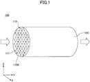
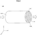
- FIGS. 1 and 2 are diagrams illustrating a filter 110 included in an exhaust gas treatment apparatus according to a first embodiment.
- the filter 110 indicates an example of a filter (DPF: Diesel Particulate Filter) configured to purify an exhaust gas of a diesel engine, and is inserted in series in an exhaust pipe discharging the exhaust gas of a diesel engine.
- DPF Diesel Particulate Filter
- the filter 110 is housed inside a metal pipe.
- the pipe is a part of an exhaust pipe that discharges the exhaust gas of the diesel engine, and is an example of a cylindrical metal casing.
- the pipe is inserted in series between a first section and a second section of the exhaust pipe discharging the exhaust gas of the diesel engine.
- the first section is closer to the diesel engine than the second section.
- the filter 110 is a columnar porous ceramic member and has multiple pores 111 and 112.
- the filter 110 may be made of, for example, ceramic made of silicon carbide (SiC).
- the filter 110 further includes a first surface 110A (see FIG. 1 ), a second surface 110B (see FIG. 2 ), and a side surface 110C. Both the first surface 110A and the second surface 110B are circular, and the side surface 110C has a shape of a side surface of a columnar body (i.e., a rectangular shape curved in an annular shape).
- the pores 111 extend along a Y axis direction from respective openings formed in the first surface 110A of the filter 110 toward the second surface 110B, and are closed immediately before the second surface 110B.
- the extending direction (i.e., Y-axis direction) of the pores 111 is equal to a direction in which a cylindrical central axis of the filter 110 extends.
- the shape of a cross section perpendicular to the extending direction of a pore 111 is, for example, a square.
- the cross section perpendicular to the extending direction of a pore 111 is a cross section parallel to an XZ plane.
- the multiple pores 111 are arranged at positions of white squares among the multiple white squares and multiple black squares arranged in a nested pattern (checkered pattern).
- the multiple pores 111 extend from the respective openings formed in the first surface 110A to positions immediately before the second surface 110B.
- the shape of a cross section perpendicular to the extending direction of a pore 112 is, for example, a square.
- the cross section perpendicular to the extending direction of a pore 112 is a cross section parallel to an XZ plane.
- the multiple pores 112 are arranged at positions of black squares among the multiple white squares and multiple black squares arranged in a nested pattern.
- the multiple pores 112 extend from the respective openings formed in the second surface 110B to positions immediately before the first surface 110A.
- the multiple pores 111 and the multiple pores 112 are arranged in a nested pattern, and are alternately arranged so as not to mutually overlap or contact three dimensionally.
- the exhaust gas flowing into the multiple pores 111 passes through pores of the filter 110 between the multiple pores 111 and the multiple pores 112 and flows out of the multiple pores 112.
- each pore 111 in the XZ planar view is 1 mm side length, which is the same size for the pores 112.
- An interval between the pores 111 and the pores 112 in an X axis direction and a Z axis direction is, for example, 300 ⁇ m.
- the diameter of the filter 110 in the XZ plan view and the length in a Y axis direction may be set to appropriate values according to the displacement or the use of the diesel engine using the exhaust gas treatment apparatus 100.
- FIG. 3 is a diagram illustrating an exhaust gas treatment apparatus 100 including the filter 110 according to the embodiment.
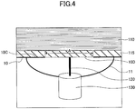
- FIG. 4 is an enlarged diagram of a part of FIG. 3 .
- the exhaust gas treatment apparatus 100 includes a pipe 10, a diesel oxidation catalyst (DOC) 20, a filter (DPF) 110, an antenna 120, a coaxial cable 130, a temperature sensor 140, and an external device 200.
- FIG. 4 indicates an insulating material 115 provided around the filter 110.
- the external device 200 includes an oscillator 210, an input matching circuit 220, a transistor 230, an output matching circuit 240, a circulator 250, a radio frequency (RF) detector 260, and a controller 270.
- an electronic control unit (ECU) 300 is connected to the controller 270.
- the filter regeneration device may further include the transistor 230. Further, the filter regeneration device may further include the temperature sensor 140, the transistor 230, and the controller 270.
- the antenna 120 constitutes a filter plugging detection device.
- the filter plugging detection device may further include the controller 270. Further, the filter plugging detection device may further include the temperature sensor 140, the transistor 230, and the controller 270.
- the pipe 10 is a part of an exhaust pipe that discharges the exhaust gas of the diesel engine, and is disposed between pipes 5A and 5B in front and rear sections.
- the pipe 10 is thicker than the pipes 5A and 5B and has a convex portion 11 on a part of an outer periphery of the pipe 10.
- the convex portion 11 corresponds to a part of the outer periphery of the pipe 10 that protrudes in a hemispherical shape.
- a filter 110 is disposed inside the pipe 10.
- the pipe 10 further includes metal plates 10A and 10B.
- the metallic plates 10A and 10B are examples of a first metal plate and a second metal plate, respectively.
- the metal plate 10A is provided on the inflow side (left side in the drawing) of the filter 110 and has vent holes through which an exhaust gas passes.
- the metal plate 10B is provided on the outflow side (right side in the drawing) of the filter 110 and has vent holes through which an exhaust gas passes.
- the vent holes of the metal plates 10A and 10B may be designed so as to minimize the resistance to the flow of the exhaust gas.
- the vent holes of the metal plates 10A and 10B may be, for example, mesh-shaped.
- Such metal plates 10A and 10B are provided such that microwaves radiated from the antenna 120 are confined in a section between the metal plate 10A and the metal plate 10B.
- the DOC 20, the filter 110, and the temperature sensor 140 are housed inside the pipe 10, and the antenna 120 is housed inside the convex portion 11.
- a core wire of the coaxial cable 130 is connected to the antenna 120 from the outside of the convex portion 11, and a shielded wire of the coaxial cable 130 is connected to the pipe 10 (body ground).
- the DOC 20 is provided on an upstream side of the filter 110, and oxidizes carbon monoxide (CO) and hydrocarbon (HC) in the exhaust gas and discharges the oxidized CO and HC to the filter 110 acting as a DPF.
- the filter 110 has a configuration as described with reference to FIGS. 1 and 2 , and is configured to remove the soot contained in the exhaust gas.
- the antenna 120 is a monopole antenna, which is provided inside the convex portion 11 and radiates a microwave to the filter 110.
- the antenna 120 is an example of a microwave radiator and is also an example of a detector.
- the microwave is used for measuring the amount of soot deposited on the filter 110 (hereinafter may also be called “soot deposition amount”), and for heating and incineration of soot.
- soot deposition amount the amount of soot deposited on the filter 110 is referred to as a degree of plugging of the filter 110.
- a partition wall 10C is disposed between the space inside the convex portion 11 and the space inside the pipe 10.
- the partition wall 10C has a configuration such that a cylindrical wall of the pipe 10 extends to the inside of the convex portion 11, and is provided with a communication port 10D at the center of the partition wall 10C.
- the communication port 10D is a circular hole, and its diameter A is set to be equal to or greater than half ( ⁇ /2) of an electrical length ( ⁇ ) of a wavelength of the microwave.
- the diameter A is set as above because the microwave radiated from the antenna 120 is efficiently radiated into the pipe 10 from the convex portion 11.
- the coaxial cable 130 is connected to the external device 200, and transmits the microwave generated by the oscillator 210 to the antenna 120.
- the frequency of the microwave is, for example, 2.45 GHz.
- the temperature sensor 140 is disposed on an outer peripheral portion of the filter 110 and measures the temperature of the filter 110.
- the temperature sensor 140 is an example of a temperature detector.
- the temperature sensor 140 may, for example, be a thermocouple.
- a signal representing the temperature of the filter 110 measured by the temperature sensor 140 is input to the controller 270 of the external device 200; the signal is used for determining the output of the microwave for heating and incinerating the soot.
- the oscillator 210 is, for example, a voltage-controlled oscillator (VCO); the oscillator 210 generates and outputs a microwave of 2.45 GHz.
- An input matching circuit 220, a transistor 230, a resistor R, an output matching circuit 240, and a circulator 250 are connected to the output side of the oscillator 210.
- a coaxial cable 130 is connected to the output side of the circulator 250.
- the oscillator 210 and the transistor 230 are examples of a microwave generator.
- the gate of the transistor 230 is connected to the oscillator 210 via the input matching circuit 220, the source of the transistor 230 is grounded, and the drain of the transistor 230 is connected to one end of the resistor R and one end of the output matching circuit 240.
- the other end of the resistor R is connected to a power supply of a predetermined voltage, and the other end of the output matching circuit 240 is connected to the circulator 250.
- the transistor 230 used may, for example, be a high electron mobility transistor made of gallium nitride (GaN-HEMT).
- GaN-HEMT is suitable for a high-power power amplifier for amplifying a microwave, and may amplify the microwave generated by the oscillator 210 into a high-power microwave.
- the circulator 250 is a three-port circuit used as a switch; the circulator 250 is configured to switch a connection destination of the coaxial cable 130 to one of the output matching circuit 240 and the RF detector 260.
- the RF detector 260 When measuring the amount (deposition amount) of soot deposited on the filter 110, the RF detector 260 receives a signal representing intensity of the microwave received by the antenna 120, and detects the intensity of the microwave received by the antenna 120 based on the intensity of the input signal. The RF detector 260 outputs a signal representing the detected intensity of the microwave to the controller 270.
- the controller 270 performs a process of measuring the amount (deposition amount) of soot deposited on the filter 110, a regeneration process of the filter 110, and the like based on instructions input from the ECU 300.
- the controller 270 and the ECU 300 are connected by a controller area network (CAN).
- CAN controller area network
- the ECU 300 performs the following process via the controller 270.
- the ECU 300 In order to measure the amount (deposition amount) of soot deposited on the filter 110, the ECU 300 causes the oscillator 210 to generate a predetermined output microwave to the controller 270. Further, after the oscillator 210 generates a microwave and radiates the generated microwave from the antenna 120 to the filter 110, the ECU 300 receives a signal representing the intensity of the microwave as detected by the RF detector 260 via the controller 270, and measures the amount (deposition amount) of soot deposited on the filter 110.
- the output of the microwave used for measurement may be determined in advance by experiment, simulation or the like, and the deposition amount of soot may be obtained based on a ratio of the intensity of the microwave received by the antenna 120 to the intensity of the microwave output from the antenna 120 to the filter 110.
- the intensity of the microwave microwave electric field intensity, output or the like may be used.
- the soot deposition amount may be obtained.
- the ECU 300 receives a signal representing the temperature of the filter 110 measured by the temperature sensor 140 via the controller 270.
- the ECU 300 determines the intensity and the radiation time of the microwave for heating/incinerating the soot (regenerating) based on the signal representing the temperature of the filter 110 and the soot deposition amount thus obtained.
- the intensity and the radiation time of the microwave for performing the regeneration process of the filter 110 may be determined in advance by experiment, simulation or the like according to the soot deposition amount. The more the soot deposition amount, the higher the microwave intensity and the longer the radiation time. As the soot deposition amount becomes less, the intensity of the microwave and the irradiation time need to be reduced.
- the temperature of the filter 110 before heating differs according to a driving state (speed, accelerator position, engine speed of the internal combustion engine, ambient temperature, etc.).
- a driving state speed, accelerator position, engine speed of the internal combustion engine, ambient temperature, etc.
- the intensity of the microwave for heating the filter 110 may be low and the radiation time may be short.
- the intensity of the microwave for heating the filter 110 may preferably be high, and the radiation time may preferably be long.
- the ECU 300 adjusts the intensity and the radiation time of the microwave according to the soot deposition amount and the temperature of the filter 110 via the controller 270.
- FIG. 5 is a diagram illustrating an operation management system including an information processing apparatus 500 of a data center.
- the information processing apparatus 500 of the data center is configured to perform radio communication with one or more vehicles 400 via a corresponding radio base station 410.
- the radio base station 410 is, for example, a base station (relay station) for radio communication using a mobile phone line.
- the information processing apparatus 500 of such a data center may be a server, or may be a virtual machine (e.g., a cloud computer) implemented by multiple servers or computers or the like.
- FIG. 6 is a diagram illustrating a configuration of the information processing apparatus 500.
- the information processing apparatus 500 includes a main controller 501, a plugging degree acquisition unit 502, a determination unit 503, a communication unit 504, and a memory 505.
- the main controller 501 is a processor configured to control over processes of the information processing apparatus 500.
- the main controller 501 communicates with the vehicle 400 and transmits an instruction signal for instructing the filter 110 to execute a regeneration process of the filter 110 to the ECU 300 of the vehicle 400 via the communication unit 504 in accordance with the deposition amount of soot, the type of loading, the traveled route, etc.
- the specific process executed by the main controller 501 will be' described later with reference to a flowchart of FIG. 8 .
- the plugging degree acquisition unit 502 is configured to acquire a signal indicating the degree of plugging detected by the antenna 120, which is used as a sensor for detecting the plugging degree, from the ECU 300 of the vehicle 400 via the communication unit 504 by radio communication.
- the plugging degree is represented by the intensity of a microwave received by the antenna 120.
- the determination unit 503 is configured to calculate a soot deposition amount of the filter 110 based on a signal (a signal representing the intensity of the received microwave) representing the degree of plugging acquired by the plugging degree acquisition unit 502.
- the soot deposition amount of the filter 110 may be obtained based on a ratio of the intensity of the microwave received by the antenna 120 to the intensity of the microwave output from the antenna 120 to the filter 110.
- the determination unit 503 is configured to hold, in advance, data representing the intensity of the microwave output from the antenna 120 to the filter 110, and to obtain the ratio between the held data (i.e., the intensity of the microwave output from the antenna 120 to the filter 110) and the plugging degree (i.e., the intensity of the microwave received by the antenna 120) so as to calculate the soot deposition amount of the filter 110.
- the soot deposition amount As the ratio of the intensity of the microwave received by the antenna 120 to the intensity of the microwave output from the antenna 120 to the filter 110 is smaller, the soot deposition amount will be smaller; as the ratio is larger, the soot deposition amount will be larger. This is because when the soot deposition amount is small, the microwave is hardly reflected by the filter 110, and when the soot deposition amount is large, the degree of reflection of the microwave by the filter 110 increases.
- a specific soot deposition amount may be obtained from the ratio of the intensity of the microwave received by the antenna 120 to the intensity of the microwave output from the antenna 120 to the filter 110.
- the determination unit 503 is configured to determine whether the calculated plugging degree is equal to or higher than a predetermined threshold degree. When the determination unit 503 determines that the plugging degree is equal to or higher than the predetermined threshold degree, the determination unit 503 causes the main controller 501 to execute a process of transmitting an instruction signal to the ECU 300 of the vehicle 400 so as to cause the ECU 300 to execute a regenerating process of the filter 110.
- the communication unit 504 is configured to perform radio communication with the ECU 300 of the vehicle 400 by radio communication using a mobile phone line.
- the communication unit 504 is a modem.
- the memory 505 is configured to store various data and the like necessary for processes performed in the data center.
- FIG. 7 is a diagram illustrating a configuration of the ECU 300.
- the ECU 300 includes a main controller 301, a deposition amount measuring unit 302, a temperature measuring unit 303, and a regeneration process execution unit 304.
- the ECU 300 is connected to the communication unit 310.
- the communication unit 310 is a modem installed in the vehicle 400 and is configured to perform radio communication with the communication unit 504 of the information processing apparatus 500 by radio communication using a mobile phone line.
- the main controller 301 is a processor configured to control the processes of the ECU 300, and to execute various processes via the controller 270. The specific process executed by the main controller 301 will be described later with reference to a flowchart of FIG. 9 .
- the deposition amount measuring unit 302 is configured to radiate a measurement microwave from the antenna 120 to the filter 110 via the controller 270, and to acquire the intensity of the microwave received by the antenna 120.
- the deposition amount measuring unit 302 is configured to transmit a signal representing the acquired intensity of the microwave to the information processing apparatus 500.
- the signal representing the intensity of the microwave is used in calculating the amount of soot deposited in the filter 110 (degree of plugging of the filter 110).
- the temperature measuring unit 303 is configured to acquire the temperature of the filter 110 measured by the temperature sensor 140 via the controller 270 in accordance with an instruction from the information processing apparatus 500. A signal representing the temperature measured by the temperature sensor 140 is input to the temperature measuring unit 303 via the controller 270.
- the regeneration process execution unit 304 is configured to perform a regeneration process of the filter 110 via the controller 270 in response to the instruction from the information processing apparatus 500.
- the regeneration process execution unit 304 determines the intensity and the radiation time of the microwave for heating/incinerating the soot (regenerating) based on the signal representing the temperature of the filter 110 and the obtained soot deposition amount.
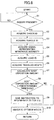
- FIG. 8 is a flowchart illustrating a process executed by an information processing apparatus 500. This flow is executed by the main controller 501, the plugging degree acquisition unit 502, the determination unit 503, and the communication unit 504.
- step S1 the main controller 501 checks the presence or absence of an inquiry from the vehicle 400 (step S1).
- the inquiry from the vehicle 400 is made to the information processing apparatus 500 when the ECU 300 of the vehicle 400 determines whether a regeneration process is necessary to execute.
- the process of step S1 is repeated until the main controller 501 detects the presence of an inquiry.
- the main controller 501 acquires a driver ID (Identification) (step S2).
- the driver ID is transmitted from the ECU 300 of the vehicle 400 to the information processing apparatus 500.
- the main controller 501 reads data representing an operation pattern associated with the driver ID in a database.
- the main controller 501 acquires a vehicle ID (Identification) (step S2).
- the vehicle ID is transmitted from the ECU 300 of the vehicle 400 to the information processing apparatus 500.
- the plugging degree acquisition unit 502 acquires a signal representing the intensity of a microwave transmitted from the vehicle 400 (step S4).
- the signal representing the intensity of the microwave is a signal representing the degree of plugging of the filter 110, which is used in calculating the amount of soot deposited in the filter 110.
- the main controller 501 acquires a load ID (step S5).
- the load ID is transmitted from the ECU 300 of the vehicle 400 to the information processing apparatus 500.
- the load ID represents a type of a package loaded by the vehicle 400.
- the main controller 501 acquires a traveled route (step S6).
- the traveled route is a history of roads or routes on which the vehicle 400 subject to being processed in the flow illustrated in FIG. 8 has traveled by the time of inquiry.
- Such a traveled route may be obtained by, for example, periodically conducting communication between the ECU 300 of the vehicle 400 and the information processing apparatus 500 to acquire, from a navigation system of the vehicle 400, data representing the roads or routes on which the vehicle 400 has been traveling.
- the determination unit 503 calculates the soot deposition amount of the filter 110 (step S7).
- the determination unit 503 calculates the soot deposition amount of the filter 110 based on a signal representing the intensity of the microwave.
- the determination unit 503 determines whether the soot deposition amount is equal to or greater than a predetermined threshold (step S8).
- the predetermined threshold value may be stored in advance in a memory 505 by the information processing apparatus 500.
- step S8 When determining that the soot deposition amount is equal to or greater than the predetermined threshold value (step S8: YES), the main controller 501 instructs the ECU 300 of the vehicle 400 to perform a regeneration process of the filter 110 (step S9).
- the main controller 501 indicates an optimum route (step S10).
- the optimum route indicates the most suitable route for performing a regeneration process among the routes to a current destination that may be taken by the vehicle 400 when the vehicle 400 performs the regeneration process.
- a route suitable for performing the regeneration process may, for example, be a route that facilitates continuous traveling of the vehicle 400 at a constant speed such as an expressway or freeway.
- the main controller 501 Upon completion of the above process, the main controller 501 returns to step S1 of the flow.
- the information processing apparatus 500 executes the flow illustrated in FIG. 8 each time an inquiry is made from any one of the vehicles 400.
- FIG. 9 is a flowchart illustrating a process executed by the ECU 300. The following process is executed by the ECU 300 via the controller 270.
- the main controller 301 starts the process at a predetermined timing and causes the oscillator 210 for measuring the deposition amount to output a microwave (step S21).
- the predetermined timing is, for example, when the travel distance of the vehicle 400 reaches a predetermined distance after the previous regeneration process, or when the fuel injection amount reaches a predetermined amount, or the like. Note that since the periodical regeneration process of the filter 110 may be conducted only at an approximate level, the method of taking the predetermined timing may be a method other than those described above.
- the deposition amount measuring unit 302 irradiates the filter 110 with the microwave for measuring the deposition amount and acquires the intensity of the microwave received from the antenna 120 (step S22).
- the signal representing the intensity of the microwave is a signal representing the degree of plugging of the filter 110, which is used in calculating the amount of soot deposited in the filter 110.
- the main controller 301 transmits a signal representing the measured soot deposition amount to the information processing apparatus 500 of the data center (step S23).
- the main controller 301 determines whether a response is received from the information processing apparatus 500 of the data center (step S24). The process of step S24 is repeatedly executed until a response is received from the information processing apparatus 500.
- the main controller 301 acquires an instruction from the information processing apparatus 500 of the data center (step S25).
- the main controller 301 determines whether the instruction acquired in step S25 is an instruction to execute the regeneration process (step S26). The process of step S26 is repeatedly executed until the main controller 301 determines that the acquired instruction is the instruction to execute the regeneration process.
- the temperature measuring unit 303 measures the temperature of the filter 110 using the temperature sensor 140 (step S27).
- the regeneration process execution unit 304 determines the intensity and the radiation time of the microwave for heating/incinerating the soot (regenerating) based on the signal representing the temperature of the filter 110 and the obtained soot deposition amount (step S28).
- the main controller 301 updates the route (step S29).
- the main controller 301 Upon completion of the above processes, the main controller 301 returns to step S1 of the flow.
- the microwave is directly radiated from the antenna 120 disposed inside the convex portion 11 of the pipe 10 to the filter 110 disposed inside the pipe 10, which may simplify the structure of the exhaust gas treatment apparatus 100.
- the exhaust gas treatment apparatus 100 includes a filter regeneration device and a filter plugging detection device, and a filter plugging determination method is performed using the exhaust gas treatment apparatus 100.
- the disclosed embodiments may provide a filter regeneration device with a simple structure, a filter plugging detection device, the exhaust gas treatment apparatus 100, and a filter plugging determination method.
- the antenna 120 since the antenna 120 is disposed inside the convex portion 11 where the outer peripheral portion of the pipe 10 protrudes outward, the antenna 120 deviates from the flow path of the exhaust gas. As a result, the antenna 120 will not interfere with the flow of the exhaust gas, which makes the antenna 120 less susceptible to being heated by the exhaust gas, less susceptible to breakage, or the like, thereby extending the life of the antenna 120.
- the soot deposition amount may be obtained based on the ratio of the intensity of the microwave received by the antenna 120 to the intensity of the microwave output from the antenna 120 to the filter 110, the intensity of the microwave may be determined according to the soot deposition amount at the time of regenerating filter 110.
- the temperature of the filter 110 may be measured by the temperature sensor 140, and the intensity of the microwave at the time of regenerating the filter 110 may be determined according to the temperature of the filter 110.
- the temperature sensor 140 may be omitted from the structure.
- the microwave generated in the oscillator 210 may be amplified to a high-power microwave.
- the method implemented by the flows of FIG. 8 and FIG. 9 is a filter plugging determination method.
- the determination unit 503 of the information processing apparatus 500 determines whether the soot deposition amount is equal to or greater than the predetermined threshold value.
- the ECU 300 may compare the soot deposition amount with a predetermined threshold value to make such a determination.
- the soot deposition amount in order to measure the soot deposition amount, a configuration of emitting microwaves from the antenna 120 and receiving microwaves reflected by the filter 110 has been proposed.
- another antenna may be provided on the side opposite to the antenna 120 with the filter 110 to be interposed between the two antennas, and the microwave radiated from the antenna 120 and transmitted through the filter 110 may be received by another antenna.
- the soot deposition amount will be smaller; and, as for a lower the received microwave intensity, the soot deposition amount will be larger.
- the antenna 120 is a monopole antenna.
- the antenna 120 may be an antenna other than the monopole antenna such as a dipole antenna or a patch antenna.
- the shape of the convex portion 11 on which the antenna 120 is disposed is not limited to a hemispherical shape, and may be any shape insofar as the shape does not interfere with the radiation and reception of microwaves.
- a filter plugging determination method for determining a plugging degree of a ceramic filter (110) based on intensity of a microwave detected by a filter plugging detection device.
- the filter plugging detection device includes a microwave radiator (120) configured to radiate a microwave and disposed to be oriented in a direction toward a ceramic filter (110) configured to purify exhaust gas of an internal combustion engine, the ceramic filter (110) being disposed in a cylindrical portion of a metallic case (10) having the cylindrical portion and having a protruding portion (11) protruding toward an outside of the cylindrical portion, the microwave radiator (120) being disposed inside the protruding portion (11), and a detector (120) configured to detect the microwave that is radiated by the microwave radiator (120) and passes through the ceramic filter (110) or that is radiated by the microwave radiator (120) and is reflected by the ceramic filter (110).
- the filter plugging determination method includes determining the plugging degree of the ceramic filter (110) based on the intensity of the microwave detected by the detector (120) to be high as the intensity of the microwave passing through the ceramic filter (110) becomes lower or the intensity of the microwave reflected by the ceramic filter (110) becomes higher, and determining the plugging degree to be low as the intensity of the microwave passing through the ceramic filter (110) becomes higher or the intensity of the microwave reflected by the ceramic filter (110) becomes lower.
- the filter regeneration device the filter plugging detection device, the exhaust gas treatment apparatus, and the filter plugging determination method of the exemplary embodiments of the present invention have been described above, the present invention is not limited to the specifically disclosed embodiment, and various modifications and changes may be possible without departing from the scope of the claims.
Landscapes
- Engineering & Computer Science (AREA)
- Chemical & Material Sciences (AREA)
- Combustion & Propulsion (AREA)
- Mechanical Engineering (AREA)
- General Engineering & Computer Science (AREA)
- Chemical Kinetics & Catalysis (AREA)
- Processes For Solid Components From Exhaust (AREA)
- Control Of High-Frequency Heating Circuits (AREA)
- Constitution Of High-Frequency Heating (AREA)
- Filtering Materials (AREA)
- Filtering Of Dispersed Particles In Gases (AREA)
Abstract
Description
- The disclosures discussed herein relate to a filter regeneration device, a filter plugging detection device, an exhaust gas treatment apparatus, and a filter plugging determination method.
- In the related art, an exhaust gas purification apparatus for an internal combustion engine that burns and removes particulate matter including carbon microparticles discharged into an exhaust passage of the internal combustion engine by a single mode microwave particulate combustion apparatus has been studied. The single mode microwave particulate combustion apparatus includes a microwave generator configured to oscillate microwaves, a microwave transmitter configured to transmit the microwaves oscillated from the microwave generator into the exhaust passage, and a standing wave generating space part provided downstream of a connecting portion with the microwave transmitter.
- The standing wave generating space part is configured to include an introducing port on one end and configured to pass an exhaust gas together with the microwave, a reflecting board on the other end and configured to reflect the microwave in a direction opposite to an exhaust flow direction, and a particulate deposition part configured to allow the particulate matter in the exhaust gas to deposit so that the deposited particulate matter is heated and burned by microwave energy.
- Further, an isolator is disposed in the microwave transmitter configured to transmit the microwave generated in the microwave generator (see, e.g., Patent Document 1).
- Patent Document 1: Japanese Laid-open Patent Publication No.
2011-252387 - As described above, the related-art exhaust purification device for an internal combustion engine includes a microwave transmitter (waveguide) and a standing wave generating space part (resonance part) provided in the exhaust passage, and further includes a waveguide with an isolator.
- However, when a waveguide is used, a resonance part and an isolator are also required, which complicates the structure.
- It is an object in one aspect of an embodiment to provide a filter regeneration device with a simple structure, a filter plugging detection device, an exhaust gas treatment apparatus, and a filter plugging determination method.
- According to an embodiment of one aspect of the invention, a filter regeneration device includes a microwave radiator configured to radiate a microwave and disposed to be oriented in a direction toward a ceramic filter configured to purify exhaust gas of an internal combustion engine, the ceramic filter being disposed in a cylindrical portion of a metallic case having the cylindrical portion and having a protruding portion protruding toward an outside of the cylindrical portion of the metallic case, the microwave radiator being disposed inside the protruding portion; and a microwave generator configured to generate the microwave radiated from the microwave radiator toward the ceramic filter.
- The disclosed embodiments may be able to provide a filter regeneration device with a simple structure, a filter plugging detection device, an exhaust gas treatment apparatus, and a filter plugging determination method.
- Embodiments of the invention are set out, by way of example only, with reference to the following drawings, in which:
-
FIG. 1 is a diagram illustrating afilter 110 included in an exhaust gas treatment apparatus according to a first embodiment; -
FIG. 2 is another diagram illustrating thefilter 110 included in the exhaust gas treatment apparatus according to the first embodiment; -
FIG. 3 is a diagram illustrating an exhaustgas treatment apparatus 100 including thefilter 110 according to the embodiment; -
FIG. 4 is an enlarged diagram of a part ofFIG. 3 ; -
FIG. 5 is a diagram illustrating an operation management system including aninformation processing apparatus 500 of a data center; -
FIG. 6 is a diagram illustrating a configuration of theinformation processing apparatus 500; -
FIG. 7 is a diagram illustrating a configuration of anECU 300; -
FIG. 8 is a flowchart illustrating a process executed by theinformation processing apparatus 500; and -
FIG. 9 is a flowchart illustrating a process executed by theECU 300. - The following describes embodiments to which a filter regeneration device, a filter plugging detection device, an exhaust gas treatment apparatus, and a filter plugging determination method of the present invention are applied.
-
FIGS. 1 and2 are diagrams illustrating afilter 110 included in an exhaust gas treatment apparatus according to a first embodiment. - The
filter 110 indicates an example of a filter (DPF: Diesel Particulate Filter) configured to purify an exhaust gas of a diesel engine, and is inserted in series in an exhaust pipe discharging the exhaust gas of a diesel engine. - The
filter 110 is housed inside a metal pipe. The pipe is a part of an exhaust pipe that discharges the exhaust gas of the diesel engine, and is an example of a cylindrical metal casing. The pipe is inserted in series between a first section and a second section of the exhaust pipe discharging the exhaust gas of the diesel engine. The first section is closer to the diesel engine than the second section. - The
filter 110 is a columnar porous ceramic member and hasmultiple pores filter 110 may be made of, for example, ceramic made of silicon carbide (SiC). - The
filter 110 further includes afirst surface 110A (seeFIG. 1 ), asecond surface 110B (seeFIG. 2 ), and aside surface 110C. Both thefirst surface 110A and thesecond surface 110B are circular, and theside surface 110C has a shape of a side surface of a columnar body (i.e., a rectangular shape curved in an annular shape). - The
pores 111 extend along a Y axis direction from respective openings formed in thefirst surface 110A of thefilter 110 toward thesecond surface 110B, and are closed immediately before thesecond surface 110B. The extending direction (i.e., Y-axis direction) of thepores 111 is equal to a direction in which a cylindrical central axis of thefilter 110 extends. - The shape of a cross section perpendicular to the extending direction of a
pore 111 is, for example, a square. The cross section perpendicular to the extending direction of apore 111 is a cross section parallel to an XZ plane. In the XZ plan view, themultiple pores 111 are arranged at positions of white squares among the multiple white squares and multiple black squares arranged in a nested pattern (checkered pattern). Themultiple pores 111 extend from the respective openings formed in thefirst surface 110A to positions immediately before thesecond surface 110B. - The shape of a cross section perpendicular to the extending direction of a
pore 112 is, for example, a square. The cross section perpendicular to the extending direction of apore 112 is a cross section parallel to an XZ plane. In the XZ plan view, themultiple pores 112 are arranged at positions of black squares among the multiple white squares and multiple black squares arranged in a nested pattern. Themultiple pores 112 extend from the respective openings formed in thesecond surface 110B to positions immediately before thefirst surface 110A. - As illustrated above, the
multiple pores 111 and themultiple pores 112 are arranged in a nested pattern, and are alternately arranged so as not to mutually overlap or contact three dimensionally. - An exhaust gas discharged from the first section of the exhaust pipe flows into the
multiple pores 111. That is, themultiple pores 111 are located on an exhaust gas inflow side of thefilter 110. Further, themultiple pores 112 discharge the purified exhaust gas to the second section of the exhaust pipe. That is, themultiple pores 112 are located on an exhaust gas outflow side of thefilter 110. - The exhaust gas flowing into the
multiple pores 111 passes through pores of thefilter 110 between themultiple pores 111 and themultiple pores 112 and flows out of themultiple pores 112. - For example, the size of each
pore 111 in the XZ planar view is 1 mm side length, which is the same size for thepores 112. An interval between thepores 111 and thepores 112 in an X axis direction and a Z axis direction is, for example, 300 µm. - Further, the diameter of the
filter 110 in the XZ plan view and the length in a Y axis direction may be set to appropriate values according to the displacement or the use of the diesel engine using the exhaustgas treatment apparatus 100. -
FIG. 3 is a diagram illustrating an exhaustgas treatment apparatus 100 including thefilter 110 according to the embodiment.FIG. 4 is an enlarged diagram of a part ofFIG. 3 . - The exhaust
gas treatment apparatus 100 includes apipe 10, a diesel oxidation catalyst (DOC) 20, a filter (DPF) 110, anantenna 120, acoaxial cable 130, atemperature sensor 140, and anexternal device 200.FIG. 4 indicates aninsulating material 115 provided around thefilter 110. - The
external device 200 includes anoscillator 210, aninput matching circuit 220, atransistor 230, anoutput matching circuit 240, acirculator 250, a radio frequency (RF)detector 260, and acontroller 270. In addition, an electronic control unit (ECU) 300 is connected to thecontroller 270. - Note that the
antenna 120 and theoscillator 210 constitute a filter regeneration device. The filter regeneration device may further include thetransistor 230. Further, the filter regeneration device may further include thetemperature sensor 140, thetransistor 230, and thecontroller 270. - In addition, the
antenna 120 constitutes a filter plugging detection device. The filter plugging detection device may further include thecontroller 270. Further, the filter plugging detection device may further include thetemperature sensor 140, thetransistor 230, and thecontroller 270. - The
pipe 10 is a part of an exhaust pipe that discharges the exhaust gas of the diesel engine, and is disposed betweenpipes pipe 10 is thicker than thepipes convex portion 11 on a part of an outer periphery of thepipe 10. Theconvex portion 11 corresponds to a part of the outer periphery of thepipe 10 that protrudes in a hemispherical shape. Afilter 110 is disposed inside thepipe 10. - The
pipe 10 further includesmetal plates metallic plates metal plate 10A is provided on the inflow side (left side in the drawing) of thefilter 110 and has vent holes through which an exhaust gas passes. Themetal plate 10B is provided on the outflow side (right side in the drawing) of thefilter 110 and has vent holes through which an exhaust gas passes. The vent holes of themetal plates metal plates -
Such metal plates antenna 120 are confined in a section between themetal plate 10A and themetal plate 10B. - The
DOC 20, thefilter 110, and thetemperature sensor 140 are housed inside thepipe 10, and theantenna 120 is housed inside theconvex portion 11. A core wire of thecoaxial cable 130 is connected to theantenna 120 from the outside of theconvex portion 11, and a shielded wire of thecoaxial cable 130 is connected to the pipe 10 (body ground). - The
DOC 20 is provided on an upstream side of thefilter 110, and oxidizes carbon monoxide (CO) and hydrocarbon (HC) in the exhaust gas and discharges the oxidized CO and HC to thefilter 110 acting as a DPF. Thefilter 110 has a configuration as described with reference toFIGS. 1 and2 , and is configured to remove the soot contained in the exhaust gas. - For example, the
antenna 120 is a monopole antenna, which is provided inside theconvex portion 11 and radiates a microwave to thefilter 110. Theantenna 120 is an example of a microwave radiator and is also an example of a detector. - The microwave is used for measuring the amount of soot deposited on the filter 110 (hereinafter may also be called "soot deposition amount"), and for heating and incineration of soot. Note that the amount (deposition amount) of soot deposited on the
filter 110 is referred to as a degree of plugging of thefilter 110. - A partition wall 10C is disposed between the space inside the
convex portion 11 and the space inside thepipe 10. The partition wall 10C has a configuration such that a cylindrical wall of thepipe 10 extends to the inside of theconvex portion 11, and is provided with acommunication port 10D at the center of the partition wall 10C. Thecommunication port 10D is a circular hole, and its diameter A is set to be equal to or greater than half (λ/2) of an electrical length (λ) of a wavelength of the microwave. The diameter A is set as above because the microwave radiated from theantenna 120 is efficiently radiated into thepipe 10 from theconvex portion 11. - The
coaxial cable 130 is connected to theexternal device 200, and transmits the microwave generated by theoscillator 210 to theantenna 120. The frequency of the microwave is, for example, 2.45 GHz. - The
temperature sensor 140 is disposed on an outer peripheral portion of thefilter 110 and measures the temperature of thefilter 110. Thetemperature sensor 140 is an example of a temperature detector. Thetemperature sensor 140 may, for example, be a thermocouple. A signal representing the temperature of thefilter 110 measured by thetemperature sensor 140 is input to thecontroller 270 of theexternal device 200; the signal is used for determining the output of the microwave for heating and incinerating the soot. - The
oscillator 210 is, for example, a voltage-controlled oscillator (VCO); theoscillator 210 generates and outputs a microwave of 2.45 GHz. Aninput matching circuit 220, atransistor 230, a resistor R, anoutput matching circuit 240, and acirculator 250 are connected to the output side of theoscillator 210. Acoaxial cable 130 is connected to the output side of thecirculator 250. Theoscillator 210 and thetransistor 230 are examples of a microwave generator. - The gate of the
transistor 230 is connected to theoscillator 210 via theinput matching circuit 220, the source of thetransistor 230 is grounded, and the drain of thetransistor 230 is connected to one end of the resistor R and one end of theoutput matching circuit 240. The other end of the resistor R is connected to a power supply of a predetermined voltage, and the other end of theoutput matching circuit 240 is connected to thecirculator 250. In this configuration, by providing theinput matching circuit 220, the resistor R, and theoutput matching circuit 240 before and after thetransistor 230, the impedance is adjusted. - The
transistor 230 used may, for example, be a high electron mobility transistor made of gallium nitride (GaN-HEMT). The GaN-HEMT is suitable for a high-power power amplifier for amplifying a microwave, and may amplify the microwave generated by theoscillator 210 into a high-power microwave. - The
circulator 250 is a three-port circuit used as a switch; thecirculator 250 is configured to switch a connection destination of thecoaxial cable 130 to one of theoutput matching circuit 240 and theRF detector 260. - When measuring the amount (deposition amount) of soot deposited on the
filter 110, theRF detector 260 receives a signal representing intensity of the microwave received by theantenna 120, and detects the intensity of the microwave received by theantenna 120 based on the intensity of the input signal. TheRF detector 260 outputs a signal representing the detected intensity of the microwave to thecontroller 270. - The
controller 270 performs a process of measuring the amount (deposition amount) of soot deposited on thefilter 110, a regeneration process of thefilter 110, and the like based on instructions input from theECU 300. Thecontroller 270 and theECU 300 are connected by a controller area network (CAN). - Specifically, the
ECU 300 performs the following process via thecontroller 270. - In order to measure the amount (deposition amount) of soot deposited on the
filter 110, theECU 300 causes theoscillator 210 to generate a predetermined output microwave to thecontroller 270. Further, after theoscillator 210 generates a microwave and radiates the generated microwave from theantenna 120 to thefilter 110, theECU 300 receives a signal representing the intensity of the microwave as detected by theRF detector 260 via thecontroller 270, and measures the amount (deposition amount) of soot deposited on thefilter 110. - The output of the microwave used for measurement may be determined in advance by experiment, simulation or the like, and the deposition amount of soot may be obtained based on a ratio of the intensity of the microwave received by the
antenna 120 to the intensity of the microwave output from theantenna 120 to thefilter 110. As an example of the intensity of the microwave, microwave electric field intensity, output or the like may be used. - Further, when the ratio between the intensity of the microwave received by the
antenna 120 to the intensity of the microwave output from theantenna 120 to thefilter 110 is determined in advance by experiment, simulation or the like, the soot deposition amount may be obtained. - The
ECU 300 receives a signal representing the temperature of thefilter 110 measured by thetemperature sensor 140 via thecontroller 270. TheECU 300 determines the intensity and the radiation time of the microwave for heating/incinerating the soot (regenerating) based on the signal representing the temperature of thefilter 110 and the soot deposition amount thus obtained. - The intensity and the radiation time of the microwave for performing the regeneration process of the
filter 110 may be determined in advance by experiment, simulation or the like according to the soot deposition amount. The more the soot deposition amount, the higher the microwave intensity and the longer the radiation time. As the soot deposition amount becomes less, the intensity of the microwave and the irradiation time need to be reduced. - Further, the temperature of the
filter 110 before heating differs according to a driving state (speed, accelerator position, engine speed of the internal combustion engine, ambient temperature, etc.). When the temperature of thefilter 110 is high, the intensity of the microwave for heating thefilter 110 may be low and the radiation time may be short. Further, when the temperature of thefilter 110 is low, the intensity of the microwave for heating thefilter 110 may preferably be high, and the radiation time may preferably be long. - Accordingly, when the soot deposited on the
filter 110 is heated, theECU 300 adjusts the intensity and the radiation time of the microwave according to the soot deposition amount and the temperature of thefilter 110 via thecontroller 270. -
FIG. 5 is a diagram illustrating an operation management system including aninformation processing apparatus 500 of a data center. Theinformation processing apparatus 500 of the data center is configured to perform radio communication with one ormore vehicles 400 via a correspondingradio base station 410. Theradio base station 410 is, for example, a base station (relay station) for radio communication using a mobile phone line. Theinformation processing apparatus 500 of such a data center may be a server, or may be a virtual machine (e.g., a cloud computer) implemented by multiple servers or computers or the like. -
FIG. 6 is a diagram illustrating a configuration of theinformation processing apparatus 500. Theinformation processing apparatus 500 includes amain controller 501, a pluggingdegree acquisition unit 502, adetermination unit 503, acommunication unit 504, and amemory 505. - The
main controller 501 is a processor configured to control over processes of theinformation processing apparatus 500. Themain controller 501 communicates with thevehicle 400 and transmits an instruction signal for instructing thefilter 110 to execute a regeneration process of thefilter 110 to theECU 300 of thevehicle 400 via thecommunication unit 504 in accordance with the deposition amount of soot, the type of loading, the traveled route, etc. The specific process executed by themain controller 501 will be' described later with reference to a flowchart ofFIG. 8 . - The plugging
degree acquisition unit 502 is configured to acquire a signal indicating the degree of plugging detected by theantenna 120, which is used as a sensor for detecting the plugging degree, from theECU 300 of thevehicle 400 via thecommunication unit 504 by radio communication. The plugging degree is represented by the intensity of a microwave received by theantenna 120. - The
determination unit 503 is configured to calculate a soot deposition amount of thefilter 110 based on a signal (a signal representing the intensity of the received microwave) representing the degree of plugging acquired by the pluggingdegree acquisition unit 502. The soot deposition amount of thefilter 110 may be obtained based on a ratio of the intensity of the microwave received by theantenna 120 to the intensity of the microwave output from theantenna 120 to thefilter 110. - The
determination unit 503 is configured to hold, in advance, data representing the intensity of the microwave output from theantenna 120 to thefilter 110, and to obtain the ratio between the held data (i.e., the intensity of the microwave output from theantenna 120 to the filter 110) and the plugging degree (i.e., the intensity of the microwave received by the antenna 120) so as to calculate the soot deposition amount of thefilter 110. - As the ratio of the intensity of the microwave received by the
antenna 120 to the intensity of the microwave output from theantenna 120 to thefilter 110 is smaller, the soot deposition amount will be smaller; as the ratio is larger, the soot deposition amount will be larger. This is because when the soot deposition amount is small, the microwave is hardly reflected by thefilter 110, and when the soot deposition amount is large, the degree of reflection of the microwave by thefilter 110 increases. - Note that by determining a relationship between the ratio of the intensity of the microwave received by the
antenna 120 to the intensity of the microwave output from theantenna 120 to thefilter 110 and the deposition amount of the soot in advance through experiments or simulations or the like, a specific soot deposition amount may be obtained from the ratio of the intensity of the microwave received by theantenna 120 to the intensity of the microwave output from theantenna 120 to thefilter 110. - The
determination unit 503 is configured to determine whether the calculated plugging degree is equal to or higher than a predetermined threshold degree. When thedetermination unit 503 determines that the plugging degree is equal to or higher than the predetermined threshold degree, thedetermination unit 503 causes themain controller 501 to execute a process of transmitting an instruction signal to theECU 300 of thevehicle 400 so as to cause theECU 300 to execute a regenerating process of thefilter 110. - The
communication unit 504 is configured to perform radio communication with theECU 300 of thevehicle 400 by radio communication using a mobile phone line. Thecommunication unit 504 is a modem. Further, thememory 505 is configured to store various data and the like necessary for processes performed in the data center. -
FIG. 7 is a diagram illustrating a configuration of theECU 300. - The
ECU 300 includes amain controller 301, a depositionamount measuring unit 302, atemperature measuring unit 303, and a regenerationprocess execution unit 304. TheECU 300 is connected to thecommunication unit 310. Thecommunication unit 310 is a modem installed in thevehicle 400 and is configured to perform radio communication with thecommunication unit 504 of theinformation processing apparatus 500 by radio communication using a mobile phone line. - The
main controller 301 is a processor configured to control the processes of theECU 300, and to execute various processes via thecontroller 270. The specific process executed by themain controller 301 will be described later with reference to a flowchart ofFIG. 9 . - In accordance with instructions from the
information processing apparatus 500, the depositionamount measuring unit 302 is configured to radiate a measurement microwave from theantenna 120 to thefilter 110 via thecontroller 270, and to acquire the intensity of the microwave received by theantenna 120. The depositionamount measuring unit 302 is configured to transmit a signal representing the acquired intensity of the microwave to theinformation processing apparatus 500. The signal representing the intensity of the microwave is used in calculating the amount of soot deposited in the filter 110 (degree of plugging of the filter 110). - The
temperature measuring unit 303 is configured to acquire the temperature of thefilter 110 measured by thetemperature sensor 140 via thecontroller 270 in accordance with an instruction from theinformation processing apparatus 500. A signal representing the temperature measured by thetemperature sensor 140 is input to thetemperature measuring unit 303 via thecontroller 270. - The regeneration
process execution unit 304 is configured to perform a regeneration process of thefilter 110 via thecontroller 270 in response to the instruction from theinformation processing apparatus 500. The regenerationprocess execution unit 304 determines the intensity and the radiation time of the microwave for heating/incinerating the soot (regenerating) based on the signal representing the temperature of thefilter 110 and the obtained soot deposition amount. -
FIG. 8 is a flowchart illustrating a process executed by aninformation processing apparatus 500. This flow is executed by themain controller 501, the pluggingdegree acquisition unit 502, thedetermination unit 503, and thecommunication unit 504. - On starting the flow (start), the
main controller 501 checks the presence or absence of an inquiry from the vehicle 400 (step S1). The inquiry from thevehicle 400 is made to theinformation processing apparatus 500 when theECU 300 of thevehicle 400 determines whether a regeneration process is necessary to execute. The process of step S1 is repeated until themain controller 501 detects the presence of an inquiry. - The
main controller 501 acquires a driver ID (Identification) (step S2). When thevehicle 400 makes an inquiry to theinformation processing apparatus 500, the driver ID is transmitted from theECU 300 of thevehicle 400 to theinformation processing apparatus 500. Themain controller 501 reads data representing an operation pattern associated with the driver ID in a database. - The
main controller 501 acquires a vehicle ID (Identification) (step S2). When thevehicle 400 makes an inquiry to theinformation processing apparatus 500, the vehicle ID is transmitted from theECU 300 of thevehicle 400 to theinformation processing apparatus 500. - The plugging
degree acquisition unit 502 acquires a signal representing the intensity of a microwave transmitted from the vehicle 400 (step S4). The signal representing the intensity of the microwave is a signal representing the degree of plugging of thefilter 110, which is used in calculating the amount of soot deposited in thefilter 110. - The
main controller 501 acquires a load ID (step S5). When thevehicle 400 makes an inquiry to theinformation processing apparatus 500, the load ID is transmitted from theECU 300 of thevehicle 400 to theinformation processing apparatus 500. The load ID represents a type of a package loaded by thevehicle 400. - The
main controller 501 acquires a traveled route (step S6). The traveled route is a history of roads or routes on which thevehicle 400 subject to being processed in the flow illustrated inFIG. 8 has traveled by the time of inquiry. Such a traveled route may be obtained by, for example, periodically conducting communication between theECU 300 of thevehicle 400 and theinformation processing apparatus 500 to acquire, from a navigation system of thevehicle 400, data representing the roads or routes on which thevehicle 400 has been traveling. - The
determination unit 503 calculates the soot deposition amount of the filter 110 (step S7). Thedetermination unit 503 calculates the soot deposition amount of thefilter 110 based on a signal representing the intensity of the microwave. - The
determination unit 503 determines whether the soot deposition amount is equal to or greater than a predetermined threshold (step S8). The predetermined threshold value may be stored in advance in amemory 505 by theinformation processing apparatus 500. - When determining that the soot deposition amount is equal to or greater than the predetermined threshold value (step S8: YES), the
main controller 501 instructs theECU 300 of thevehicle 400 to perform a regeneration process of the filter 110 (step S9). - The
main controller 501 indicates an optimum route (step S10). The optimum route indicates the most suitable route for performing a regeneration process among the routes to a current destination that may be taken by thevehicle 400 when thevehicle 400 performs the regeneration process. A route suitable for performing the regeneration process may, for example, be a route that facilitates continuous traveling of thevehicle 400 at a constant speed such as an expressway or freeway. - Upon completion of the above process, the
main controller 501 returns to step S1 of the flow. In order to communicate withmultiple vehicles 400, theinformation processing apparatus 500 executes the flow illustrated inFIG. 8 each time an inquiry is made from any one of thevehicles 400. -
FIG. 9 is a flowchart illustrating a process executed by theECU 300. The following process is executed by theECU 300 via thecontroller 270. - The
main controller 301 starts the process at a predetermined timing and causes theoscillator 210 for measuring the deposition amount to output a microwave (step S21). The predetermined timing is, for example, when the travel distance of thevehicle 400 reaches a predetermined distance after the previous regeneration process, or when the fuel injection amount reaches a predetermined amount, or the like. Note that since the periodical regeneration process of thefilter 110 may be conducted only at an approximate level, the method of taking the predetermined timing may be a method other than those described above. - The deposition
amount measuring unit 302 irradiates thefilter 110 with the microwave for measuring the deposition amount and acquires the intensity of the microwave received from the antenna 120 (step S22). The signal representing the intensity of the microwave is a signal representing the degree of plugging of thefilter 110, which is used in calculating the amount of soot deposited in thefilter 110. - The
main controller 301 transmits a signal representing the measured soot deposition amount to theinformation processing apparatus 500 of the data center (step S23). - The
main controller 301 determines whether a response is received from theinformation processing apparatus 500 of the data center (step S24). The process of step S24 is repeatedly executed until a response is received from theinformation processing apparatus 500. - The
main controller 301 acquires an instruction from theinformation processing apparatus 500 of the data center (step S25). - The
main controller 301 determines whether the instruction acquired in step S25 is an instruction to execute the regeneration process (step S26). The process of step S26 is repeatedly executed until themain controller 301 determines that the acquired instruction is the instruction to execute the regeneration process. - The
temperature measuring unit 303 measures the temperature of thefilter 110 using the temperature sensor 140 (step S27). - The regeneration
process execution unit 304 determines the intensity and the radiation time of the microwave for heating/incinerating the soot (regenerating) based on the signal representing the temperature of thefilter 110 and the obtained soot deposition amount (step S28). - The
main controller 301 updates the route (step S29). - Upon completion of the above processes, the
main controller 301 returns to step S1 of the flow. - As described above, according to the embodiment, the microwave is directly radiated from the
antenna 120 disposed inside theconvex portion 11 of thepipe 10 to thefilter 110 disposed inside thepipe 10, which may simplify the structure of the exhaustgas treatment apparatus 100. The exhaustgas treatment apparatus 100 includes a filter regeneration device and a filter plugging detection device, and a filter plugging determination method is performed using the exhaustgas treatment apparatus 100. - The disclosed embodiments may provide a filter regeneration device with a simple structure, a filter plugging detection device, the exhaust
gas treatment apparatus 100, and a filter plugging determination method. - In addition, since the
antenna 120 is disposed inside theconvex portion 11 where the outer peripheral portion of thepipe 10 protrudes outward, theantenna 120 deviates from the flow path of the exhaust gas. As a result, theantenna 120 will not interfere with the flow of the exhaust gas, which makes theantenna 120 less susceptible to being heated by the exhaust gas, less susceptible to breakage, or the like, thereby extending the life of theantenna 120. - Further, since the soot deposition amount may be obtained based on the ratio of the intensity of the microwave received by the
antenna 120 to the intensity of the microwave output from theantenna 120 to thefilter 110, the intensity of the microwave may be determined according to the soot deposition amount at the time of regeneratingfilter 110. - In addition, the temperature of the
filter 110 may be measured by thetemperature sensor 140, and the intensity of the microwave at the time of regenerating thefilter 110 may be determined according to the temperature of thefilter 110. In order to simplify the structure of the exhaustgas treatment apparatus 100, thetemperature sensor 140 may be omitted from the structure. - Further, since a GaN-HEMT is used as the
transistor 230, the microwave generated in theoscillator 210 may be amplified to a high-power microwave. - The method implemented by the flows of
FIG. 8 andFIG. 9 is a filter plugging determination method. According to the above description, thedetermination unit 503 of theinformation processing apparatus 500 determines whether the soot deposition amount is equal to or greater than the predetermined threshold value. However, theECU 300 may compare the soot deposition amount with a predetermined threshold value to make such a determination. - Further, according to the above description, in order to measure the soot deposition amount, a configuration of emitting microwaves from the
antenna 120 and receiving microwaves reflected by thefilter 110 has been proposed. Alternatively, another antenna may be provided on the side opposite to theantenna 120 with thefilter 110 to be interposed between the two antennas, and the microwave radiated from theantenna 120 and transmitted through thefilter 110 may be received by another antenna. In this case, as for a higher the intensity of the microwave received, the soot deposition amount will be smaller; and, as for a lower the received microwave intensity, the soot deposition amount will be larger. - According to the above description, the
antenna 120 is a monopole antenna. However, theantenna 120 may be an antenna other than the monopole antenna such as a dipole antenna or a patch antenna. - Further, the shape of the
convex portion 11 on which theantenna 120 is disposed is not limited to a hemispherical shape, and may be any shape insofar as the shape does not interfere with the radiation and reception of microwaves. - According to an aspect of the embodiments, a filter plugging determination method for determining a plugging degree of a ceramic filter (110) based on intensity of a microwave detected by a filter plugging detection device is disclosed. The filter plugging detection device includes a microwave radiator (120) configured to radiate a microwave and disposed to be oriented in a direction toward a ceramic filter (110) configured to purify exhaust gas of an internal combustion engine, the ceramic filter (110) being disposed in a cylindrical portion of a metallic case (10) having the cylindrical portion and having a protruding portion (11) protruding toward an outside of the cylindrical portion, the microwave radiator (120) being disposed inside the protruding portion (11), and a detector (120) configured to detect the microwave that is radiated by the microwave radiator (120) and passes through the ceramic filter (110) or that is radiated by the microwave radiator (120) and is reflected by the ceramic filter (110). The filter plugging determination method includes determining the plugging degree of the ceramic filter (110) based on the intensity of the microwave detected by the detector (120) to be high as the intensity of the microwave passing through the ceramic filter (110) becomes lower or the intensity of the microwave reflected by the ceramic filter (110) becomes higher, and determining the plugging degree to be low as the intensity of the microwave passing through the ceramic filter (110) becomes higher or the intensity of the microwave reflected by the ceramic filter (110) becomes lower.
- Although the filter regeneration device, the filter plugging detection device, the exhaust gas treatment apparatus, and the filter plugging determination method of the exemplary embodiments of the present invention have been described above, the present invention is not limited to the specifically disclosed embodiment, and various modifications and changes may be possible without departing from the scope of the claims.
Claims (12)
- A filter regeneration device comprising:a microwave radiator (120) configured to radiate a microwave and disposed to be oriented in a direction toward a ceramic filter (110) configured to purify exhaust gas of an internal combustion engine, the ceramic filter (110) being disposed in a cylindrical portion of a metallic case (10) having the cylindrical portion and having a protruding portion (11) protruding toward an outside of the cylindrical portion of the metallic case (10), the microwave radiator (120) being disposed inside the protruding portion (11); anda microwave generator (210, 230) configured to generate the microwave radiated from the microwave radiator (120) toward the ceramic filter (110).
- The filter regeneration device as claimed in claim 1, wherein
the microwave generator (210, 230) includes a high electron mobility transistor (230) made of gallium nitride. - The filter regeneration device as claimed in claim 1 or 2, further comprising:a temperature detector (140) disposed on an outer circumference of the ceramic filter (110) and configured to measure a temperature of the ceramic filter (110); andan output controller configured to control output of the microwave generated by the microwave generator (210, 230), whereinthe output controller lowers the output of the microwave generated by the microwave generator (210, 230) as the temperature detected by the temperature detector (140) becomes higher, and raises the output of the microwave generated by the microwave generator (210, 230) as the temperature detected by the temperature detector (140) becomes lower.
- A filter plugging detection device comprising:a microwave radiator (120) configured to radiate a microwave and disposed to be oriented in a direction toward a ceramic filter (110) configured to purify exhaust gas of an internal combustion engine, the ceramic filter (110) being disposed in a cylindrical portion of a metallic case (10) having the cylindrical portion and having a protruding portion (11) protruding toward an outside of the cylindrical portion, the microwave radiator (120) being disposed inside the protruding portion (11); anda detector (120) configured to detect the microwave that is radiated by the microwave radiator (120) and passes through the ceramic filter (110) or that is radiated by the microwave radiator (120) and is reflected by the ceramic filter (110).
- The filter plugging detection device as claimed in claim 4, further comprising:a determination unit (503) configured to determine a plugging degree of the ceramic filter (110) based on intensity of the microwave detected by the detector (120).
- The filter plugging detection as claimed in claim 4 or 5, further comprising:a temperature detector (140) configured to measure a temperature of the ceramic filter (110) and disposed on an outer circumference of the ceramic filter (110).
- An exhaust gas treatment apparatus (100) comprising:a ceramic filter (110) configured to purify exhaust gas of an internal combustion engine, the ceramic filter (110) being disposed in a cylindrical portion of a metallic case (10) having the cylindrical portion and having a protruding portion (11) protruding toward an outside of the cylindrical portion;a microwave radiator (120) configured to radiate a microwave toward the ceramic filter (110) and disposed inside the protruding portion of the metallic case (10); anda microwave generator (210, 230) configured to generate the microwave radiated from the microwave radiator (120) toward the ceramic filter (110).
- The exhaust gas treatment apparatus (100) as claimed in claim 7, wherein
the microwave generator (210, 230) includes a high electron mobility transistor (230) made of gallium nitride. - The exhaust gas treatment apparatus (100) as claimed in claim 7 or 8, further comprising:a temperature detector (140) disposed on an outer circumference of the ceramic filter (110) and configured to measure a temperature of the ceramic filter (110); andan output controller configured to control output of the microwave generated by the microwave generator (210, 230), whereinthe output controller (270) lowers the output of the microwave generated by the microwave generator (210, 230) as the temperature detected by the temperature detector (140) becomes higher, and raises the output of the microwave generated by the microwave generator (210, 230) as the temperature detected by the temperature detector (140) becomes lower.
- The exhaust gas treatment apparatus (100) as claimed in any of claims 7 to 9, wherein
the protruding portion (11) is disposed, with respect to a flow path direction in which the exhaust gas flows through the ceramic filter (110), on an outer peripheral portion of the ceramic filter (110) at an interval between an inflow end through which an exhaust gas flows into the ceramic filter (110) and an exhaust end from which the exhaust gas is exhausted from the ceramic filter (110). - The exhaust gas treatment apparatus (100) as claimed in any of claims 7 to 10, further comprising:a first metal plate (10A) disposed on an inflow side of the ceramic filter (110) inside the metal casing (10) and having first vent holes through which the exhaust gas flowing into the ceramic filter (110) passes; anda second metal plate (10B) disposed on an exhaust side of the ceramic filter (110) inside the metal casing (10) and having second vent holes through which the exhaust gas flowing out of the ceramic filter (110) passes.
- The exhaust gas treatment apparatus (100) as claimed in any of claims 7 to 11, further comprising:a partition wall (10C) partitioning an interval between the protruding portion (11) and the cylindrical portion, the partition wall (10C) having an opening configured to connect the protruding portion (11) and the cylindrical portion.
Applications Claiming Priority (1)
| Application Number | Priority Date | Filing Date | Title |
|---|---|---|---|
| JP2016190288A JP6737109B2 (en) | 2016-09-28 | 2016-09-28 | Filter regeneration device, filter clogging detection device, exhaust gas treatment device, and filter clogging determination method |
Publications (2)
| Publication Number | Publication Date |
|---|---|
| EP3301270A1 true EP3301270A1 (en) | 2018-04-04 |
| EP3301270B1 EP3301270B1 (en) | 2022-03-30 |
Family
ID=59579410
Family Applications (1)
| Application Number | Title | Priority Date | Filing Date |
|---|---|---|---|
| EP17185009.2A Not-in-force EP3301270B1 (en) | 2016-09-28 | 2017-08-04 | Filter regeneration device, filter plugging detection device, and exhaust gas treatment apparatus |
Country Status (3)
| Country | Link |
|---|---|
| US (1) | US10526944B2 (en) |
| EP (1) | EP3301270B1 (en) |
| JP (1) | JP6737109B2 (en) |
Families Citing this family (3)
| Publication number | Priority date | Publication date | Assignee | Title |
|---|---|---|---|---|
| JP6881363B2 (en) * | 2018-03-16 | 2021-06-02 | トヨタ自動車株式会社 | Abnormality diagnostic device |
| JP6828706B2 (en) * | 2018-03-22 | 2021-02-10 | トヨタ自動車株式会社 | Internal combustion engine exhaust purification system |
| JP7414033B2 (en) * | 2020-03-30 | 2024-01-16 | 株式会社富士通ゼネラル | Air treatment equipment and air treatment method |
Citations (8)
| Publication number | Priority date | Publication date | Assignee | Title |
|---|---|---|---|---|
| EP0469237A1 (en) * | 1990-08-03 | 1992-02-05 | STROMERZEUGUNG GmbH & CO. ANLAGENBAU KG | Process and device for converting molecules in a fluid stream |
| JPH04183914A (en) * | 1990-11-16 | 1992-06-30 | Matsushita Electric Ind Co Ltd | Filter regenerator for internal combustion engine |
| EP0506083A1 (en) * | 1991-03-29 | 1992-09-30 | Matsushita Electric Industrial Co., Ltd. | A filter regenerating apparatus for an internal combustion engine |
| JPH04295121A (en) * | 1991-03-26 | 1992-10-20 | Matsushita Electric Ind Co Ltd | Filter for internal combustion engine and filter regeneration device |
| JPH04298623A (en) * | 1991-03-28 | 1992-10-22 | Matsushita Electric Ind Co Ltd | Filter regeneration device for internal combustion engine |
| JPH08109817A (en) * | 1994-10-12 | 1996-04-30 | Matsushita Electric Ind Co Ltd | Filter regeneration device for internal combustion engine |
| WO2009008525A1 (en) * | 2007-07-12 | 2009-01-15 | Imagineering, Inc. | Exhaust gas substance purifier |
| JP2011252387A (en) | 2010-05-31 | 2011-12-15 | Denso Corp | Exhaust emission control device of internal combustion engine |
Family Cites Families (8)
| Publication number | Priority date | Publication date | Assignee | Title |
|---|---|---|---|---|
| JP2725938B2 (en) * | 1992-02-21 | 1998-03-11 | 三洋電機株式会社 | High frequency heating equipment |
| JP2738251B2 (en) * | 1993-01-20 | 1998-04-08 | 松下電器産業株式会社 | Filter regeneration device for internal combustion engine |
| US20020069756A1 (en) * | 1995-10-26 | 2002-06-13 | Mako Frederick M. | Method and apparatus for regeneration of particulate filter using microwave energy |
| US20040009112A1 (en) * | 2002-07-10 | 2004-01-15 | Advanced Composite Materials Corporation | Silicon carbide fibers essentially devoid of whiskers and method for preparation thereof |
| US20100050619A1 (en) * | 2008-09-03 | 2010-03-04 | Houston Advanced Research Center | Nanotechnology Based Heat Generation and Usage |
| US20100212299A1 (en) * | 2009-02-25 | 2010-08-26 | Jacob George | Methods for determining when to regenerate exhaust gas particulate filters |
| US20150089924A1 (en) | 2012-04-26 | 2015-04-02 | Hitachi Kokusai Electric Inc. | Exhaust gas processing device, exhaust gas processing system, method for controlling exhaust gas processing system, control program, and cylindrical tube |
| CN105789296B (en) * | 2015-12-29 | 2019-01-25 | 中国电子科技集团公司第五十五研究所 | A kind of aluminum gallium nitride compound/gallium nitride high electron mobility transistor |
-
2016
- 2016-09-28 JP JP2016190288A patent/JP6737109B2/en not_active Expired - Fee Related
-
2017
- 2017-08-04 EP EP17185009.2A patent/EP3301270B1/en not_active Not-in-force
- 2017-08-14 US US15/676,935 patent/US10526944B2/en active Active
Patent Citations (8)
| Publication number | Priority date | Publication date | Assignee | Title |
|---|---|---|---|---|
| EP0469237A1 (en) * | 1990-08-03 | 1992-02-05 | STROMERZEUGUNG GmbH & CO. ANLAGENBAU KG | Process and device for converting molecules in a fluid stream |
| JPH04183914A (en) * | 1990-11-16 | 1992-06-30 | Matsushita Electric Ind Co Ltd | Filter regenerator for internal combustion engine |
| JPH04295121A (en) * | 1991-03-26 | 1992-10-20 | Matsushita Electric Ind Co Ltd | Filter for internal combustion engine and filter regeneration device |
| JPH04298623A (en) * | 1991-03-28 | 1992-10-22 | Matsushita Electric Ind Co Ltd | Filter regeneration device for internal combustion engine |
| EP0506083A1 (en) * | 1991-03-29 | 1992-09-30 | Matsushita Electric Industrial Co., Ltd. | A filter regenerating apparatus for an internal combustion engine |
| JPH08109817A (en) * | 1994-10-12 | 1996-04-30 | Matsushita Electric Ind Co Ltd | Filter regeneration device for internal combustion engine |
| WO2009008525A1 (en) * | 2007-07-12 | 2009-01-15 | Imagineering, Inc. | Exhaust gas substance purifier |
| JP2011252387A (en) | 2010-05-31 | 2011-12-15 | Denso Corp | Exhaust emission control device of internal combustion engine |
Also Published As
| Publication number | Publication date |
|---|---|
| JP6737109B2 (en) | 2020-08-05 |
| JP2018053793A (en) | 2018-04-05 |
| US20180087421A1 (en) | 2018-03-29 |
| US10526944B2 (en) | 2020-01-07 |
| EP3301270B1 (en) | 2022-03-30 |
Similar Documents
| Publication | Publication Date | Title |
|---|---|---|
| EP3301270B1 (en) | Filter regeneration device, filter plugging detection device, and exhaust gas treatment apparatus | |
| US10876458B2 (en) | Microwave irradiation device, exhaust purification apparatus, automobile and management system | |
| JP2017130307A (en) | Microwave irradiation device, exhaust gas purifier, heating device and chemical reaction device | |
| JP6186990B2 (en) | Vehicle control system, vehicle control device, and portable communication terminal | |
| US20180098390A1 (en) | Detecting apparatus and heating apparatus | |
| US10577992B2 (en) | Microwave heating apparatus and exhaust gas purification apparatus | |
| JP7697448B2 (en) | Information processing device, vehicle, information processing method, and information processing program | |
| CN115515825A (en) | TDR-Based System and Method for Hand Detection on Steering Wheel Eliminating Aging and Environmental Effects | |
| CN110418975B (en) | Radar device and target position detection method of radar device | |
| CN104220709A (en) | Exhaust gas processing device, exhaust gas processing system, method for controlling exhaust gas processing system, control program, and cylindrical tube | |
| EP3540192B1 (en) | Abnormality diagnosis apparatus | |
| US10697339B2 (en) | Using electromagnetic waves and/or injection to facilitate operation of catalytic converters | |
| JP2016053341A (en) | Exhaust emission control device | |
| US20180347422A1 (en) | Fine particle detector and exhaust gas purification apparatus | |
| US10746076B2 (en) | Particulate matter detection circuit and filter processing device | |
| CN110259550B (en) | Abnormality diagnosis device | |
| US20150300226A1 (en) | Em energy application for treating exhaust gases | |
| WO2011074667A1 (en) | Pm sensor | |
| JP6604111B2 (en) | Filter device | |
| JP6737110B2 (en) | Filter device, vehicle, filter device monitoring system, and filter device monitoring program | |
| JP2007247477A (en) | Exhaust gas treatment equipment and exhaust gas treatment method | |
| JP2004080114A (en) | In-vehicle device for automatic toll collection system | |
| JP6888448B2 (en) | Deterioration judgment device | |
| KR19980040368A (en) | Proximity range warning device | |
| JPH06288226A (en) | Diesel exhaust emission control device |
Legal Events
| Date | Code | Title | Description |
|---|---|---|---|
| PUAI | Public reference made under article 153(3) epc to a published international application that has entered the european phase |
Free format text: ORIGINAL CODE: 0009012 |
|
| STAA | Information on the status of an ep patent application or granted ep patent |
Free format text: STATUS: THE APPLICATION HAS BEEN PUBLISHED |
|
| AK | Designated contracting states |
Kind code of ref document: A1 Designated state(s): AL AT BE BG CH CY CZ DE DK EE ES FI FR GB GR HR HU IE IS IT LI LT LU LV MC MK MT NL NO PL PT RO RS SE SI SK SM TR |
|
| AX | Request for extension of the european patent |
Extension state: BA ME |
|
| STAA | Information on the status of an ep patent application or granted ep patent |
Free format text: STATUS: REQUEST FOR EXAMINATION WAS MADE |
|
| 17P | Request for examination filed |
Effective date: 20180522 |
|
| RBV | Designated contracting states (corrected) |
Designated state(s): AL AT BE BG CH CY CZ DE DK EE ES FI FR GB GR HR HU IE IS IT LI LT LU LV MC MK MT NL NO PL PT RO RS SE SI SK SM TR |
|
| STAA | Information on the status of an ep patent application or granted ep patent |
Free format text: STATUS: EXAMINATION IS IN PROGRESS |
|
| 17Q | First examination report despatched |
Effective date: 20200707 |
|
| GRAP | Despatch of communication of intention to grant a patent |
Free format text: ORIGINAL CODE: EPIDOSNIGR1 |
|
| STAA | Information on the status of an ep patent application or granted ep patent |
Free format text: STATUS: GRANT OF PATENT IS INTENDED |
|
| INTG | Intention to grant announced |
Effective date: 20211020 |
|
| GRAS | Grant fee paid |
Free format text: ORIGINAL CODE: EPIDOSNIGR3 |
|
| GRAA | (expected) grant |
Free format text: ORIGINAL CODE: 0009210 |
|
| STAA | Information on the status of an ep patent application or granted ep patent |
Free format text: STATUS: THE PATENT HAS BEEN GRANTED |
|
| AK | Designated contracting states |
Kind code of ref document: B1 Designated state(s): AL AT BE BG CH CY CZ DE DK EE ES FI FR GB GR HR HU IE IS IT LI LT LU LV MC MK MT NL NO PL PT RO RS SE SI SK SM TR |
|
| REG | Reference to a national code |
Ref country code: GB Ref legal event code: FG4D |
|
| REG | Reference to a national code |
Ref country code: CH Ref legal event code: EP |
|
| REG | Reference to a national code |
Ref country code: DE Ref legal event code: R096 Ref document number: 602017055131 Country of ref document: DE |
|
| REG | Reference to a national code |
Ref country code: AT Ref legal event code: REF Ref document number: 1479384 Country of ref document: AT Kind code of ref document: T Effective date: 20220415 |
|
| REG | Reference to a national code |
Ref country code: IE Ref legal event code: FG4D |
|
| REG | Reference to a national code |
Ref country code: LT Ref legal event code: MG9D |
|
| PG25 | Lapsed in a contracting state [announced via postgrant information from national office to epo] |
Ref country code: SE Free format text: LAPSE BECAUSE OF FAILURE TO SUBMIT A TRANSLATION OF THE DESCRIPTION OR TO PAY THE FEE WITHIN THE PRESCRIBED TIME-LIMIT Effective date: 20220330 Ref country code: RS Free format text: LAPSE BECAUSE OF FAILURE TO SUBMIT A TRANSLATION OF THE DESCRIPTION OR TO PAY THE FEE WITHIN THE PRESCRIBED TIME-LIMIT Effective date: 20220330 Ref country code: NO Free format text: LAPSE BECAUSE OF FAILURE TO SUBMIT A TRANSLATION OF THE DESCRIPTION OR TO PAY THE FEE WITHIN THE PRESCRIBED TIME-LIMIT Effective date: 20220630 Ref country code: LT Free format text: LAPSE BECAUSE OF FAILURE TO SUBMIT A TRANSLATION OF THE DESCRIPTION OR TO PAY THE FEE WITHIN THE PRESCRIBED TIME-LIMIT Effective date: 20220330 Ref country code: HR Free format text: LAPSE BECAUSE OF FAILURE TO SUBMIT A TRANSLATION OF THE DESCRIPTION OR TO PAY THE FEE WITHIN THE PRESCRIBED TIME-LIMIT Effective date: 20220330 Ref country code: BG Free format text: LAPSE BECAUSE OF FAILURE TO SUBMIT A TRANSLATION OF THE DESCRIPTION OR TO PAY THE FEE WITHIN THE PRESCRIBED TIME-LIMIT Effective date: 20220630 |
|
| REG | Reference to a national code |
Ref country code: NL Ref legal event code: MP Effective date: 20220330 |
|
| REG | Reference to a national code |
Ref country code: AT Ref legal event code: MK05 Ref document number: 1479384 Country of ref document: AT Kind code of ref document: T Effective date: 20220330 |
|
| PG25 | Lapsed in a contracting state [announced via postgrant information from national office to epo] |
Ref country code: LV Free format text: LAPSE BECAUSE OF FAILURE TO SUBMIT A TRANSLATION OF THE DESCRIPTION OR TO PAY THE FEE WITHIN THE PRESCRIBED TIME-LIMIT Effective date: 20220330 Ref country code: GR Free format text: LAPSE BECAUSE OF FAILURE TO SUBMIT A TRANSLATION OF THE DESCRIPTION OR TO PAY THE FEE WITHIN THE PRESCRIBED TIME-LIMIT Effective date: 20220701 Ref country code: FI Free format text: LAPSE BECAUSE OF FAILURE TO SUBMIT A TRANSLATION OF THE DESCRIPTION OR TO PAY THE FEE WITHIN THE PRESCRIBED TIME-LIMIT Effective date: 20220330 |
|
| PG25 | Lapsed in a contracting state [announced via postgrant information from national office to epo] |
Ref country code: NL Free format text: LAPSE BECAUSE OF FAILURE TO SUBMIT A TRANSLATION OF THE DESCRIPTION OR TO PAY THE FEE WITHIN THE PRESCRIBED TIME-LIMIT Effective date: 20220330 |
|
| PG25 | Lapsed in a contracting state [announced via postgrant information from national office to epo] |
Ref country code: SM Free format text: LAPSE BECAUSE OF FAILURE TO SUBMIT A TRANSLATION OF THE DESCRIPTION OR TO PAY THE FEE WITHIN THE PRESCRIBED TIME-LIMIT Effective date: 20220330 Ref country code: SK Free format text: LAPSE BECAUSE OF FAILURE TO SUBMIT A TRANSLATION OF THE DESCRIPTION OR TO PAY THE FEE WITHIN THE PRESCRIBED TIME-LIMIT Effective date: 20220330 Ref country code: RO Free format text: LAPSE BECAUSE OF FAILURE TO SUBMIT A TRANSLATION OF THE DESCRIPTION OR TO PAY THE FEE WITHIN THE PRESCRIBED TIME-LIMIT Effective date: 20220330 Ref country code: PT Free format text: LAPSE BECAUSE OF FAILURE TO SUBMIT A TRANSLATION OF THE DESCRIPTION OR TO PAY THE FEE WITHIN THE PRESCRIBED TIME-LIMIT Effective date: 20220801 Ref country code: ES Free format text: LAPSE BECAUSE OF FAILURE TO SUBMIT A TRANSLATION OF THE DESCRIPTION OR TO PAY THE FEE WITHIN THE PRESCRIBED TIME-LIMIT Effective date: 20220330 Ref country code: EE Free format text: LAPSE BECAUSE OF FAILURE TO SUBMIT A TRANSLATION OF THE DESCRIPTION OR TO PAY THE FEE WITHIN THE PRESCRIBED TIME-LIMIT Effective date: 20220330 Ref country code: CZ Free format text: LAPSE BECAUSE OF FAILURE TO SUBMIT A TRANSLATION OF THE DESCRIPTION OR TO PAY THE FEE WITHIN THE PRESCRIBED TIME-LIMIT Effective date: 20220330 Ref country code: AT Free format text: LAPSE BECAUSE OF FAILURE TO SUBMIT A TRANSLATION OF THE DESCRIPTION OR TO PAY THE FEE WITHIN THE PRESCRIBED TIME-LIMIT Effective date: 20220330 |
|
| PG25 | Lapsed in a contracting state [announced via postgrant information from national office to epo] |
Ref country code: PL Free format text: LAPSE BECAUSE OF FAILURE TO SUBMIT A TRANSLATION OF THE DESCRIPTION OR TO PAY THE FEE WITHIN THE PRESCRIBED TIME-LIMIT Effective date: 20220330 Ref country code: IS Free format text: LAPSE BECAUSE OF FAILURE TO SUBMIT A TRANSLATION OF THE DESCRIPTION OR TO PAY THE FEE WITHIN THE PRESCRIBED TIME-LIMIT Effective date: 20220730 Ref country code: AL Free format text: LAPSE BECAUSE OF FAILURE TO SUBMIT A TRANSLATION OF THE DESCRIPTION OR TO PAY THE FEE WITHIN THE PRESCRIBED TIME-LIMIT Effective date: 20220330 |
|
| REG | Reference to a national code |
Ref country code: DE Ref legal event code: R097 Ref document number: 602017055131 Country of ref document: DE |
|
| PG25 | Lapsed in a contracting state [announced via postgrant information from national office to epo] |
Ref country code: DK Free format text: LAPSE BECAUSE OF FAILURE TO SUBMIT A TRANSLATION OF THE DESCRIPTION OR TO PAY THE FEE WITHIN THE PRESCRIBED TIME-LIMIT Effective date: 20220330 |
|
| PLBE | No opposition filed within time limit |
Free format text: ORIGINAL CODE: 0009261 |
|
| STAA | Information on the status of an ep patent application or granted ep patent |
Free format text: STATUS: NO OPPOSITION FILED WITHIN TIME LIMIT |
|
| 26N | No opposition filed |
Effective date: 20230103 |
|
| PG25 | Lapsed in a contracting state [announced via postgrant information from national office to epo] |
Ref country code: MC Free format text: LAPSE BECAUSE OF FAILURE TO SUBMIT A TRANSLATION OF THE DESCRIPTION OR TO PAY THE FEE WITHIN THE PRESCRIBED TIME-LIMIT Effective date: 20220330 |
|
| REG | Reference to a national code |
Ref country code: CH Ref legal event code: PL |
|
| PG25 | Lapsed in a contracting state [announced via postgrant information from national office to epo] |
Ref country code: LU Free format text: LAPSE BECAUSE OF NON-PAYMENT OF DUE FEES Effective date: 20220804 Ref country code: LI Free format text: LAPSE BECAUSE OF NON-PAYMENT OF DUE FEES Effective date: 20220831 Ref country code: CH Free format text: LAPSE BECAUSE OF NON-PAYMENT OF DUE FEES Effective date: 20220831 |
|
| REG | Reference to a national code |
Ref country code: BE Ref legal event code: MM Effective date: 20220831 |
|
| PG25 | Lapsed in a contracting state [announced via postgrant information from national office to epo] |
Ref country code: SI Free format text: LAPSE BECAUSE OF FAILURE TO SUBMIT A TRANSLATION OF THE DESCRIPTION OR TO PAY THE FEE WITHIN THE PRESCRIBED TIME-LIMIT Effective date: 20220330 |
|
| PG25 | Lapsed in a contracting state [announced via postgrant information from national office to epo] |
Ref country code: IT Free format text: LAPSE BECAUSE OF FAILURE TO SUBMIT A TRANSLATION OF THE DESCRIPTION OR TO PAY THE FEE WITHIN THE PRESCRIBED TIME-LIMIT Effective date: 20220330 Ref country code: IE Free format text: LAPSE BECAUSE OF NON-PAYMENT OF DUE FEES Effective date: 20220804 |
|
| PG25 | Lapsed in a contracting state [announced via postgrant information from national office to epo] |
Ref country code: BE Free format text: LAPSE BECAUSE OF NON-PAYMENT OF DUE FEES Effective date: 20220831 |
|
| PGFP | Annual fee paid to national office [announced via postgrant information from national office to epo] |
Ref country code: GB Payment date: 20230629 Year of fee payment: 7 |
|
| PGFP | Annual fee paid to national office [announced via postgrant information from national office to epo] |
Ref country code: FR Payment date: 20230703 Year of fee payment: 7 Ref country code: DE Payment date: 20230627 Year of fee payment: 7 |
|
| PG25 | Lapsed in a contracting state [announced via postgrant information from national office to epo] |
Ref country code: HU Free format text: LAPSE BECAUSE OF FAILURE TO SUBMIT A TRANSLATION OF THE DESCRIPTION OR TO PAY THE FEE WITHIN THE PRESCRIBED TIME-LIMIT; INVALID AB INITIO Effective date: 20170804 |
|
| PG25 | Lapsed in a contracting state [announced via postgrant information from national office to epo] |
Ref country code: MK Free format text: LAPSE BECAUSE OF FAILURE TO SUBMIT A TRANSLATION OF THE DESCRIPTION OR TO PAY THE FEE WITHIN THE PRESCRIBED TIME-LIMIT Effective date: 20220330 Ref country code: CY Free format text: LAPSE BECAUSE OF FAILURE TO SUBMIT A TRANSLATION OF THE DESCRIPTION OR TO PAY THE FEE WITHIN THE PRESCRIBED TIME-LIMIT Effective date: 20220330 |
|
| PG25 | Lapsed in a contracting state [announced via postgrant information from national office to epo] |
Ref country code: TR Free format text: LAPSE BECAUSE OF FAILURE TO SUBMIT A TRANSLATION OF THE DESCRIPTION OR TO PAY THE FEE WITHIN THE PRESCRIBED TIME-LIMIT Effective date: 20220330 |
|
| PG25 | Lapsed in a contracting state [announced via postgrant information from national office to epo] |
Ref country code: MT Free format text: LAPSE BECAUSE OF FAILURE TO SUBMIT A TRANSLATION OF THE DESCRIPTION OR TO PAY THE FEE WITHIN THE PRESCRIBED TIME-LIMIT Effective date: 20220330 |
|
| REG | Reference to a national code |
Ref country code: DE Ref legal event code: R119 Ref document number: 602017055131 Country of ref document: DE |
|
| GBPC | Gb: european patent ceased through non-payment of renewal fee |
Effective date: 20240804 |
|
| PG25 | Lapsed in a contracting state [announced via postgrant information from national office to epo] |
Ref country code: DE Free format text: LAPSE BECAUSE OF NON-PAYMENT OF DUE FEES Effective date: 20250301 |
|
| PG25 | Lapsed in a contracting state [announced via postgrant information from national office to epo] |
Ref country code: GB Free format text: LAPSE BECAUSE OF NON-PAYMENT OF DUE FEES Effective date: 20240804 |
|
| PG25 | Lapsed in a contracting state [announced via postgrant information from national office to epo] |
Ref country code: FR Free format text: LAPSE BECAUSE OF NON-PAYMENT OF DUE FEES Effective date: 20240831 |