EP3301238A1 - Profile member with return and tabs and associated spacer - Google Patents
Profile member with return and tabs and associated spacer Download PDFInfo
- Publication number
- EP3301238A1 EP3301238A1 EP17182697.7A EP17182697A EP3301238A1 EP 3301238 A1 EP3301238 A1 EP 3301238A1 EP 17182697 A EP17182697 A EP 17182697A EP 3301238 A1 EP3301238 A1 EP 3301238A1
- Authority
- EP
- European Patent Office
- Prior art keywords
- profile
- spacer
- wing
- tongue
- wall structure
- Prior art date
- Legal status (The legal status is an assumption and is not a legal conclusion. Google has not performed a legal analysis and makes no representation as to the accuracy of the status listed.)
- Granted
Links
Images


Classifications
-
- E—FIXED CONSTRUCTIONS
- E04—BUILDING
- E04B—GENERAL BUILDING CONSTRUCTIONS; WALLS, e.g. PARTITIONS; ROOFS; FLOORS; CEILINGS; INSULATION OR OTHER PROTECTION OF BUILDINGS
- E04B9/00—Ceilings; Construction of ceilings, e.g. false ceilings; Ceiling construction with regard to insulation
- E04B9/06—Ceilings; Construction of ceilings, e.g. false ceilings; Ceiling construction with regard to insulation characterised by constructional features of the supporting construction, e.g. cross section or material of framework members
- E04B9/12—Connections between non-parallel members of the supporting construction
- E04B9/127—Connections between non-parallel members of the supporting construction one member being discontinuous and abutting against the other member
Definitions
- the present invention relates to a wall structure composed of a grid network.
- It relates more particularly to a profile for primary wall structure and a secondary framework spacer forming such a structure.
- the profiles of the primary framework are connected to a support, and the spacers of the secondary framework are mounted on the primary framework, usually orthogonally.
- the profiles used to produce the primary framework have a so-called "C” or "I” section. They most often have a bottom flange, that is to say a flat portion forming a support intended to extend in a plane parallel to that of the support, an upper flange, and a core (or middle part) connecting the lower sole to the upper sole and participating in the rigidity of the profile.
- the upper sole is traditionally connected to a hanger.
- the bottom flange is intended to be removed from the support in the mounted position while the upper flange is intended to be disposed on the support side in the mounted position.
- the spacers of the secondary frame are generally connected to the profiles of the primary frame by screws, or sometimes through a connecting device that can take the form of a loop or stirrup.
- the objective of the present invention is not only to simplify the implementation of a structure intended both for the production of false ceilings and bulkheads (any wall generally) and thus make it faster, but also to facilitate the production of profiles and spacers for forming this structure.
- the present invention also aims to simplify the implementation of the structure by reducing the number of elements necessary for the establishment and fixing of the spacers on the profiles and minimizing the risk of injury to a user.
- profile means a structure, a beam, primary frame, generally having a constant section, but where certain elements can be made punctually.
- the present invention also aims to provide a structure allowing ranges beyond three meters.
- the present invention also aims to allow a variable distribution of the spacers on the profiles.
- a profile for primary frame wall comprises a core, having at its base a lower flange forming a support, said flange comprising at least one wing forming an angle with the core, said flange having an end comprising a return, the core and the return extending from the same first face of the wing.
- the first face of the wing or the core comprises at least one tongue forming a stop in translation in a longitudinal direction (d) of the profile.
- wall a ceiling or a vertical partition such as a wall of a room.
- Such a profile generally of generally "I” shape, makes it possible to easily guide a spacer (for example in “U”), as defined later, when it is placed in position thanks to the wing return, and the tongue allows stop and hold the spacer in position.
- the cooperation between the tongue and the wing return allows a precise and easy positioning, of limit the translations, and retain a spacer during a vertical positioning of the profile.
- the profile generally has an "I" configuration.
- the return is orthogonal to the wing
- the soul is orthogonal to the sole.
- Such a tongue is formed of a blade attached on the one hand by a root, in this case to a surface formed by the first face of the flange of the sole or the core, and having a free end of other part, ie an opening.
- the tongue is also slightly elevated relative to the surface area to allow the spacer to be inserted.
- Such a tab is also occasionally called "latch" in the field considered.
- the profile comprises two tabs in opposite directions.
- Two tabs in opposite directions make the mechanical assembly more convenient and efficient.
- Two tabs in opposite directions also make it possible to overcome a predetermination of a direction of installation of the profile. This is particularly interesting when the profiles serve as a primary frame against a vertical wall, where the profiles are then preferably positioned so that an opening of the tongue is directed upward, ie its root down, so that a spacer can come to bear against the bottom of the tongue, ie against its root, by gravity.
- a profile as defined here has at least two tabs in opposite directions, there is thus always one of the two tongues in the direction for receiving a spacer abutting against its root if the profile is positioned on a vertical wall.
- the profile comprises several pairs of tongues in opposite directions.
- connection is understood to mean that two tabs are arranged in opposite directions back to back with a reduced space between them.
- Back-to-back means that the roots of the tongues of a pair are positioned side by side.
- a tongue has in front of it a space at least equal to a width of a spacer so that a spacer can be inserted.
- two consecutive tongues are in the same direction, it will be the space between the opening of a first tongue and the root of a second tongue.
- two successive tabs are in opposite directions, it will be the space between the opening of a first tab and the opening of a second tab. It is considered in this case that the first and the second tab are "face to face".
- the second tongue then belongs to another pair than that of the first tongue if the tongues are arranged in pairs.
- the core comprises at least one locking lug limiting displacement in a direction orthogonal to the wing.
- Such hearing provides stability to the spacer in a direction outside a plane defined by the profile flange, especially when screwing a plate.
- the tongue may have insufficient strength to avoid on its own lifting the spacer relative to the sole of the profile for example.
- the locking hole is equidistant from two tongues in opposite directions facing each other.
- the profile has for example at least one plane of symmetry, or two planes of symmetry, even three planes of symmetry which allows to install the profile in any sense.
- Is also proposed a spacer for secondary wall structure, comprising a lateral passage at one end configured to receive a locking tongue in translation relative to a profile and a cutout configured to cooperate with a wing return of a profile forming a translation guide means.
- the spacer has a generally "U" shape, with a bottom and two side flanks.
- two passages are formed on either side in the sidewalls for positioning the spacer independently of its direction and the positioning of the tabs of the profile.
- passage is meant here an opening, a lumen, formed laterally in the spacer, formed in a side of the spacer.
- the cutout extends from one side to the other and crosses the bottom of the spacer.
- the cutout extends for example all along a body of the spacer, but according to a particularly interesting example, the cutout has a slot shape, adapted to receive the wing return of the profile.
- flanks of the spacer have a flange, for example orthogonal to the sidewall, intended to bear against a locking hole formed in the core of a profile when the spacer is mounted on the profile.
- the spacer has a detent hump for cooperating with the blade of a tongue which then preferably has a corrugated shape to promote a locking of the spacer on the profile.
- the spacer has for example a plane of symmetry, or even two planes of symmetry, which facilitates the positioning of the spacer.
- the wall structure for example vertical, horizontal, inclined or stepped, comprises a grid network, the grid network being formed on the one hand of a primary framework of profiles as defined above, and on the other hand a secondary framework spacers as defined above, a spacer being positioned in abutment on a wing of a profile, and orthogonally to the profile, a tongue of the profile being inserted into a passage of the spacer, and a wing return of the profile being engaged in a cutout of the spacer.
- a flange of the spacer is in abutment against a locking hole formed in the core of the profile, for example to prevent the escape of the spacer when screwing the plate on said spacer.
- the wall structure comprises for example at least a first section and a second section connected by at least one splice.
- the splint comprises for example a core having an active surface from which extend an upper wing and a lower wing.
- the soul of the splint is in abutment against the core of at least the first profile, and for example the lower flange of the splint is in abutment against the lower sole of the splint.
- at least the first section and optionally the upper flange of the splint is in abutment against the upper flange of at least the first section if the at least first section further comprises an upper flange.
- at least one of the upper wing and the lower wing of the splice is positioned between the web of the at least first profile and at least one tongue formed on a first face of the wing of the at least first profile.
- a splice thus ensures continuity between two profiles.
- a splice is for example located on each side of the web of the profile if necessary to increase the rigidity and / or the robustness of the structure.
- the soul of the splint has at least one raised louver on its active surface to limit a displacement of a spacer in a direction orthogonal to the wing of one of the profiles.
- the splice has for example a cutout through which is positioned a hearing of a profile to provide this function of maintaining the spacer.
- Such splice has for example at least one plane of symmetry, and preferably two planes of symmetry to be easily and quickly inserted into the continuity of two consecutive profiles.
- two splints can, for example, be assembled to buttress two profiles at a different angle, such as for example a ceiling with redents.
- the web of the splice comprises, for example, a hole, allowing, for example, bolting, and is assembled back to back with a second splice connected to the second profile, the at least one splice and the second splice forming between them. an angle. The angle can be adjusted as needed when both profiles are butted.
- the laying of the spacers is thus simple and fast and can be done by a single user.
- the tabs allow instant attachment of the spacers with operating sets allowing great flexibility of implementation, as well as a simplified and quick installation.
- a wall structure for example to make a false ceiling, comprises at least one assembly 1 between a profile 2 and a spacer 3.
- the section 2 is part of a primary frame of the structure. It comprises a core 200, having here an upper sole 201, and at its base a lower sole 202 forming a support.
- the lower sole 202 comprises at least one wing 203 forming an angle with the core 200.
- the lower sole 202 here has two wings symmetrical with respect to the core 200, located on either side of the core 200, which ensures a better stability and a better balance to the profile 2.
- Each wing 203 has an end including a return 204, here formed orthogonally to the wing 203.
- the core 200 and the return 204 extending from the same first face 209 of the wing 203.
- the return 204 further has a hem 205 to minimize the risk of injury to a user compared to a raw edge for example.
- Such a hem 205 also contributes to stiffening the section 2.
- the upper sole 201 has a structure identical to the lower sole 202, and they are preferably formed orthogonally to the core 200.
- the upper sole 201 could be devoid of return 204 for example.
- the profile 2 is here composed of two elements having generally a configuration in "C” placed back to back and connected by clinching or rivets for example (here by clinching).
- the profile thus has a generally "I” shape, which gives it for example a symmetry along a plane passing between the two "C”.
- C element is understood to mean that each element has at least one lower wing and one upper wing with their corresponding return, as well as a portion of the web of the profile forming the back of the "C".
- the lower wings form the lower sole 202 and the upper wings form the upper sole 201, and the backs of the "C” form the core 200 of the profile 2.
- the clinching allowing for example the assembly of the two elements, is preferably performed after folding elements "C" to not mechanically solicit the connection points.
- section 2 from a single sheet of steel (or other material) folded and folded on itself.
- a tongue 206, 206 ', 206 "capable of forming a translational stop is formed on the same first face 209 of the wing 203 as that mentioned above, at least on the bottom flange 202.
- the tongue 206, 206 ', 206 "thus forms a means for attaching a spacer 3 to the section 2.
- each wing of the profile 2 comprises at least one tongue 206, 206 ', 206 ".
- At least the wing 203 comprises several tabs 206, 206 ', 206 ", or all the wings of the section 2 comprise several tabs 206, 206', 206".
- a tab 206, 206 ', 206 "comes from the wing 203 of the section 2.
- a tongue 206, 206 ', 206 "comprises a blade 210, 210', waiting, and connected to the flange 203 by a root 207, 207 ', 207" on which is impaled laterally, until it comes into contact. stop, one end 301 of a spacer 3.
- a tab 206, 206 ', 206 " is a piece, in the form of a tab or a finger, made by cutting the wing 203 and by folding to form a zone, a blade, 210, 210 'generally parallel to the wing 203 on the side of the face 209 through a connecting zone to the wing 203, the root 207, 207', 207 ".
- the tabs 206, 206', 206" are for example all in the same direction, or some of the tabs may be in opposite directions , for example one tab out of two.
- Two tabs in opposite directions are for example represented by the tabs 206 and 206 ', or 206 and 206 ".
- two tabs 206 and 206 ' are positioned in bird's wings, ie back to back. They then form a double-tongue, a pair. A distance separating their respective roots 207 and 207 'is then for example reduced to a minimum.
- a tongue 206 is sufficiently far away from a tab 206 "which faces it so that a spacer can be inserted in.
- Two tabs facing each other are for example represented by the tongues 206 and 206" which are then not part of the same pair.
- Two consecutive tongues are for example spaced from each other by 100 mm, or 200 mm, for example, offering the possibility of varying the distribution of the spacers 3.
- the profile also comprises a locking lug 208.
- the locking lug 208 is for example formed in the core 200 of the section 2, for example by cutting and stamping. It is positioned so that it forms a support for a flange 305 of a spacer 3 so that the spacer 3 is prevented from moving away, lifting, from the flange 203 of the lower flange 202 on which it is climb.
- the locking hole 208 is preferably centered with respect to two tabs 206, 206" face to face.
- a spacer 3 can be locked on a tab 206 or a tab 206 "while having a flange 305 resting on the locking lug 208, thus avoiding an escape of the spacer 3 when screwing plates on the spacer3.
- a distance separating a root 207 from a tongue 206 from a root 207 "of a tongue 206" facing it is then for example approximately equal to twice a width (e) of a spacer 3.
- a spacer is brought into position as shown by the spacer 3 '. It is placed on the wing 203, and is translated, slid on one side or the other (left or right) as shown in the spacer 3 (which has been translated to the left) and the spacer 3 "(which has been translated to the right).
- the section 2 not only has locking holes 208 for a spacer 3 which would be positioned on a lower flange of the lower flange 202, but also the locking holes 208 '(in itself identical to a hearing 208) for a spacer which would be positioned on an upper wing of the upper sole 201.
- the indication 208 or 208 ' is here of course arbitrary and allows, in the context of this description, to be able to differentiate according to whether it refers to a lower part or upper profile.
- a locking groove 208 'oriented towards the upper sole 201 is particularly useful if the upper sole 201 comprises at least one tab 206,206', 206 ".
- two consecutive openings 208 are for example spaced 100 mm or 200 mm, or for example all the openings 208 of a section 2 are spaced from each other by the same distance.
- the profile 2 thus has for example a plane of symmetry parallel to the axis (d) passing between the openings 208 and 208 ', and another plane of symmetry orthogonal to the axis (d), passing for example at middle of the profile according to its dimension along the axis (d).
- a profile 2 may have one, two or three planes of symmetry according to the embodiment envisaged.
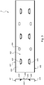
- the presented embodiment Figures 2a to 2c presents three planes of symmetry, whereas that of the figure 1 present at least one or two.
- the spacer 3 has mainly a body 300 and a (generally two) end 301 mounting.
- the body 300 of the spacer 3 generally represents a portion of the spacer 3 situated between two sections 2.
- a spacer 3 has, for example, a length between two profiles 2 (that is to say a body length) allowing a distribution of these profiles 2 every 1.20 m or 1.50 m.
- the spacer 3 is here in a generally "U” configuration, a bottom 306 and two side flanks 304 each have a flange 305 formed here by an end of the flank 304 folded at right angles.
- the end 301 of the spacer 3 also has a cutout 303 here in the form of a slot, which can be made for example by notching.
- the cut 303 here extends from one flank 304 to the other and also passes through the bottom 306 so that the spacer 3 can bear against the return 204 of the flange 203 of the profile 2.
- the end 301 also here has a recess 307 which is particularly useful if the profile comprises a locking lug 208 (or 208 '), since it then allows it to be bypassed when the spacer 3 is put in position on the profile 2, as shown in the spacer in position 3 '.
- the notch 307 is for example made by notching.
- the end 301 further has a lateral passage 302, an opening in which is inserted a tongue.
- a passage 302 is also optionally made by notching.
- the end 301 comprises two passages 302 formed in each of the flanks 304 to allow attachment of the spacer 3 on a tongue on either side indifferently.
- the spacer 3 has for example a plane or two planes of symmetry.
- the spacer 3 then has at least one plane of symmetry, or preferably two planes of symmetry.
- the blade 210, 210 'of a tongue 206, 206', 206 "has a generally undulating form, in the form of wave, so as to be able to produce a detent, for example on a boss 308 formed on the bottom 306 of the spacer 3.
- a snap promotes a locking of the spacer 3 on the profile 2.
- the joint cooperations between the wing return 203 203 and the cutout 303, between a tongue 206, 206 ', 206 "and a passage 302, and between a flange 305 of a spacer flank 304 3 with a hearing locking members 208 allow a robust assembly minimizing relative movements between the spacer 3 and the profile 2, with easy assembly, fast, and secure.
- the locking hole 208 and the face 209 of the wing 203 have a distance equivalent to a height h of the spacer 3 so that it is locked in height once in position, ie in an orthogonal direction at the wing 203.
- the cooperation between the wing return 203 203 and the cut 303 allows blocking in a direction orthogonal to the core 200 and a translational guide along the wing 204 return 204 and the cooperation between a tab 206, 206 ', 206 "and its passage 302 allows precise positioning of the spacer 3 on the section 2 allowing the aforementioned blockages.
- a wall structure optionally comprises a splint 4 in the continuity between two profiles 2, for example if it is necessary to increase the range distance.
- the splint 4 comprises a core 400 having an active surface 403 from which extend an upper flange 401 and a lower flange 402.
- the upper wing 401 and the lower wing 402 are of identical sizes.
- the web 400 of the splint 4 thus bears against the web 200 of at least a first section 2, and the lower wing 402 of the splint 4 abuts against the lower flange 202 of at least the first profile 2 and the upper flange 401 of the splint 4 bears against the upper flange 201 of at least the first profile 2.
- the upper wing 401 and the lower wing 402 of the fishplate 4 are then each positioned between the web 200 of at least the first section 2 and at least one tongue 206, 206 ', 206 "formed on a first face 209 of a wing 203 of the lower sole 202 and the upper sole 201 of the section 2 (as is visible for example figure 4 ).
- the splint 4 is thus locked at the bottom of the profiles 2.
- the web 400 of the splice 4 furthermore has gills 408, 408 'in relief on the active surface 403 to limit a displacement of a spacer 3 in a direction orthogonal to the flange 203 of one of the profiles 2 when these are assembled.
- the core 400 of the splice 4 comprises for example passages 404, here oblong, to position for example vis-à-vis assembly points 211, for example clinching.
- one end of a section 2 is devoid of hearing 208, 208 'if gills 408,408' are present on the splice 4, and a back 405 of the core 400 of the splice 4 is possible devoid of any element in relief to promote surface-to-surface contact between the splice 4 and the profile 2, ie more precisely between the back 405 of the splice 4 and a surface 200 'of the core 200 of the profile 2.
- the splint 4 thus has two planes of symmetry.
- figure 5 presents another embodiment of a splint according to the invention.
- a splint 4 according to such an embodiment is for example intended for a section 2 whose upper flange 201 is devoid of pawls 206, 206 ', 206 "and gills 208' in the corresponding upper part of the core 200
- the splint 4 here has the core 400 having the active surface 403 from which the upper flange 401 and the lower flange 402 extend. figure 5 that the upper wing 401 is longer than the lower wing 402.
- the core 400 of the splint 4 as shown figure 5 is in abutment against the core 200 of the section 2 (whose upper flange 201 is devoid of pawl 206, 206 ', 206 ", and hearing 208' in the corresponding upper part of the core 200).
- 402 of the splice 4 is then in abutment against the lower sole 202 of the profile 2 between the core 200 of the profile 2 and at least one tongue 206, 206 ', 206 "formed on a first face 209 of the wing 203 of the bottom flange 202 of the profile 2.
- the upper flange 401 of the splint 4 is in abutment against the upper flange 201 of the profile 2, between the core 200 of the profile 2 and a return 204 of a flange 203 of the upper sole 201.
- a splint 4 thus makes it possible to ensure continuity between two profiles 2.
- a splice 4 is for example located on each side of the core 200 of the profile 2 if necessary to increase the rigidity and / or the robustness of the structure.
- the core 400 of the splice 4 has a cutout 406 through which is positioned an opening 208 of a profile 2 to provide this function of maintaining the spacer when the structure is assembled. It is then preventable that the section 2 is devoid of openings 208 towards its ends.
- such a fishplate 4 has a hole 407 (for example with a diameter of 6.2 mm), formed in the core 400 which is ready at one end, for example towards a middle of a height of the core 400, that is to say at equal distances from the upper wing 401 and the lower wing 402 for example.
- a hole 407 makes it possible, for example, to bolt back-to-back of two fishplates 4 in order to abut two sections 2, no longer in a linear fashion, but with an adjustable angle (eg attics, ceilings, etc.).
- Such a splint thus has a single plane of symmetry.
- the splice 4 has the choice of a lower flange 402 and / or an upper flange 401, the lower flange 402 and the upper flange 401 may be of identical or different sizes if
- the splint comprises both the lower flange 402 and the upper flange 401, optionally at least one lug 408 in the lower part, or optionally at least one louvre 408 'in the upper part, at least one cutout 406, and if required least one passage 404.
Abstract
Une structure de paroi comporte un réseau quadrillé formé d'une ossature primaire de profilés (2) et d'une ossature secondaire d'entretoises (3). Le profilé (2) comporte une âme (200) présentant à sa base une semelle inférieure (202) formant appui qui comporte au moins une aile (203) dont une première face (209) ou l'âme (200) comprend au moins une languette (206, 206', 206") formant une butée en translation, et l'entretoise (3) comprend un passage latéral (302) à une extrémité (301) configurée pour recevoir la languette (206, 206', 206") du profilé (2) et une découpe (303) configurée pour coopérer avec un retour (204) d'aile (203) d'un profilé (2) formant un moyen de guidage en translation. Si nécessaire, deux profilés (2) consécutifs sont reliés par une éclisse adaptée.A wall structure comprises a grid network formed of a primary framework of sections (2) and a secondary framework of spacers (3). The profile (2) comprises a core (200) having at its base a lower flange (202) forming a support which comprises at least one flange (203) of which a first face (209) or the core (200) comprises at least one tongue (206, 206 ', 206 ") forming a translational stop, and the spacer (3) comprises a side passage (302) at one end (301) configured to receive the tongue (206, 206', 206") profile (2) and a cutout (303) configured to cooperate with a wing return (204) (203) of a profile (2) forming a translation guide means. If necessary, two consecutive profiles (2) are connected by a suitable splint.
Description
La présente invention concerne une structure de paroi composée d'un réseau quadrillé.The present invention relates to a wall structure composed of a grid network.
Elle concerne plus particulièrement un profilé pour ossature primaire de paroi et une entretoise d'ossature secondaire formant une telle structure.It relates more particularly to a profile for primary wall structure and a secondary framework spacer forming such a structure.
Traditionnellement, les profilés de l'ossature primaire sont reliés à un support, et les entretoises de l'ossature secondaire sont montées sur l'ossature primaire, généralement de façon orthogonale.Traditionally, the profiles of the primary framework are connected to a support, and the spacers of the secondary framework are mounted on the primary framework, usually orthogonally.
De manière usuelle, les profilés mis en oeuvre pour réaliser l'ossature primaire ont une section dite en « C » ou en « I ». Ils présentent le plus souvent une semelle inférieure, c'est-à-dire une partie plate formant appui destinée à s'étendre dans un plan parallèle à celui du support, une semelle supérieure, ainsi qu'une âme (ou partie médiane) reliant la semelle inférieure à la semelle supérieure et participant à la rigidité du profilé.In the usual way, the profiles used to produce the primary framework have a so-called "C" or "I" section. They most often have a bottom flange, that is to say a flat portion forming a support intended to extend in a plane parallel to that of the support, an upper flange, and a core (or middle part) connecting the lower sole to the upper sole and participating in the rigidity of the profile.
Dans le cas où la structure est destinée à la réalisation d'un faux plafond, la semelle supérieure est traditionnellement reliée à une suspente.In the case where the structure is intended for the realization of a false ceiling, the upper sole is traditionally connected to a hanger.
En outre, la semelle inférieure est destinée à être éloignée du support en position montée tandis que la semelle supérieure est destinée à être disposée du côté du support en position montée.In addition, the bottom flange is intended to be removed from the support in the mounted position while the upper flange is intended to be disposed on the support side in the mounted position.
Les termes « inférieur » et « supérieur » désignant les semelles sont bien entendu interchangeables et ne servent qu'à distinguer les deux semelles du profilé.The terms "lower" and "upper" designating the soles are of course interchangeable and only serve to distinguish the two soles of the profile.
Les entretoises de l'ossature secondaire sont généralement reliées aux profilés de l'ossature primaire par des vis, ou parfois grâce à un dispositif de liaison pouvant prendre une forme de boucle ou d'étrier.The spacers of the secondary frame are generally connected to the profiles of the primary frame by screws, or sometimes through a connecting device that can take the form of a loop or stirrup.
On connait par exemple le document
L'objectif de la présente invention est non seulement de simplifier la mise en oeuvre d'une structure destinée aussi bien à la réalisation de faux plafond que de cloison (toute paroi de manière générale) et la rendre ainsi plus rapide, mais aussi de faciliter la réalisation des profilés et des entretoises destinés à former cette structure.The objective of the present invention is not only to simplify the implementation of a structure intended both for the production of false ceilings and bulkheads (any wall generally) and thus make it faster, but also to facilitate the production of profiles and spacers for forming this structure.
La présente invention vise en outre à simplifier la mise en oeuvre de la structure en réduisant le nombre d'éléments nécessaires à la mise en place et à la fixation des entretoises sur les profilés et en minimisant des risques de blessure pour un utilisateur.The present invention also aims to simplify the implementation of the structure by reducing the number of elements necessary for the establishment and fixing of the spacers on the profiles and minimizing the risk of injury to a user.
On entend ici par « profilé » une structure, une poutre, d'ossature primaire, ayant globalement une section constante, mais où certains éléments peuvent être réalisés ponctuellement.Here, the term "profile" means a structure, a beam, primary frame, generally having a constant section, but where certain elements can be made punctually.
La présente invention vise aussi à proposer une structure permettant des portées au-delà de trois mètres.The present invention also aims to provide a structure allowing ranges beyond three meters.
La présente invention vise encore à permettre une répartition variable des entretoises sur les profilés.The present invention also aims to allow a variable distribution of the spacers on the profiles.
La structure de paroi telle que définie dans la revendication 1 permet de répondre au moins en partie aux problèmes précités. Un profilé pour ossature primaire en paroi, comporte une âme, présentant à sa base une semelle inférieure formant appui, ladite semelle comportant au moins une aile formant un angle avec l'âme, ladite aile présentant une extrémité comprenant un retour, l'âme et le retour s'étendant depuis une même première face de l'aile. La première face de l'aile ou l'âme comprend au moins une languette formant une butée en translation suivant une direction longitudinale (d) du profilé.The wall structure as defined in claim 1 satisfies at least some of the aforementioned problems. A profile for primary frame wall, comprises a core, having at its base a lower flange forming a support, said flange comprising at least one wing forming an angle with the core, said flange having an end comprising a return, the core and the return extending from the same first face of the wing. The first face of the wing or the core comprises at least one tongue forming a stop in translation in a longitudinal direction (d) of the profile.
On entend par exemple ici par paroi un plafond ou une cloison verticale comme par exemple un mur d'une pièce.For example here is meant by wall a ceiling or a vertical partition such as a wall of a room.
Un tel profilé, généralement de forme globalement en « I », permet de guider facilement une entretoise (par exemple en « U »), telle que définie ultérieurement, lors de sa mise en position grâce au retour d'aile, et la languette permet d'arrêter et maintenir l'entretoise en position. La coopération entre la languette et le retour d'aile permet ainsi un positionnement précis et facile, de limiter les translations, et retenir une entretoise lors d'un positionnement vertical du profilé.Such a profile, generally of generally "I" shape, makes it possible to easily guide a spacer (for example in "U"), as defined later, when it is placed in position thanks to the wing return, and the tongue allows stop and hold the spacer in position. The cooperation between the tongue and the wing return allows a precise and easy positioning, of limit the translations, and retain a spacer during a vertical positioning of the profile.
Selon un exemple de réalisation, le profilé présente globalement une configuration en « I ».According to an exemplary embodiment, the profile generally has an "I" configuration.
Par exemple, le retour est orthogonal à l'aile, et l'âme est orthogonale à la semelle.For example, the return is orthogonal to the wing, and the soul is orthogonal to the sole.
Une telle languette est formée d'une lame rattachée d'une part par une racine, en l'occurrence à une surface formée par la première face de l'aile de la semelle ou l'âme, et présentant une extrémité libre d'autre part, i.e. une ouverture. La languette est en outre légèrement en surélévation par rapport à la surface considérée pour permettre à l'entretoise de venir s'insérer. Une telle languette est aussi occasionnellement nommée « linguet » dans le domaine considéré.Such a tongue is formed of a blade attached on the one hand by a root, in this case to a surface formed by the first face of the flange of the sole or the core, and having a free end of other part, ie an opening. The tongue is also slightly elevated relative to the surface area to allow the spacer to be inserted. Such a tab is also occasionally called "latch" in the field considered.
Selon un mode de réalisation, le profilé comprend deux languettes en sens opposés.According to one embodiment, the profile comprises two tabs in opposite directions.
Deux languettes en sens opposés rendent l'assemblage mécanique plus pratique et efficace. Deux languettes en sens opposés, par exemple sur la même surface du profilé, permettent en outre de s'affranchir d'une prédétermination d'un sens de pose du profilé. Ceci est notamment intéressant lorsque les profilés servent en ossature primaire contre une paroi verticale, où les profilés sont alors de préférence positionnés de sorte qu'une ouverture de la languette soit dirigée en haut, i.e. sa racine en bas, pour qu'une entretoise puisse venir en appui au fond de la languette, i.e. contre sa racine, par gravité. Lorsqu'un profilé tel que défini ici présente au moins deux languettes en sens opposés, il y a ainsi toujours une des deux languettes dans le sens permettant de recevoir une entretoise en butée contre sa racine si le profilé est positionné sur une paroi verticale.Two tabs in opposite directions make the mechanical assembly more convenient and efficient. Two tabs in opposite directions, for example on the same surface of the profile, also make it possible to overcome a predetermination of a direction of installation of the profile. This is particularly interesting when the profiles serve as a primary frame against a vertical wall, where the profiles are then preferably positioned so that an opening of the tongue is directed upward, ie its root down, so that a spacer can come to bear against the bottom of the tongue, ie against its root, by gravity. When a profile as defined here has at least two tabs in opposite directions, there is thus always one of the two tongues in the direction for receiving a spacer abutting against its root if the profile is positioned on a vertical wall.
Selon un mode de réalisation, le profilé comprend plusieurs paires de languettes en sens opposés.According to one embodiment, the profile comprises several pairs of tongues in opposite directions.
C'est-à-dire au moins deux paires de languettes en sens opposés.That is, at least two pairs of tongues in opposite directions.
On entend alors par « paire » que deux languettes sont disposées en sens opposés dos à dos avec un espace réduit entre elles. On entend par dos à dos que les racines des languettes d'une paire sont positionnées côte à côte.The term "pair" is understood to mean that two tabs are arranged in opposite directions back to back with a reduced space between them. Back-to-back means that the roots of the tongues of a pair are positioned side by side.
Selon un exemple privilégié de réalisation et quel que soit le sens de positionnement des languettes, une languette dispose devant elle d'un espace au moins égal à une largeur d'une entretoise afin qu'une entretoise puisse venir s'insérer. On entend par « devant » la languette que l'espace se situe du côté de l'extrémité libre de la lame, de l'ouverture. Par exemple, si deux languettes consécutives sont dans le même sens, il s'agira de l'espace entre l'ouverture d'une première languette et de la racine d'une deuxième languette. Selon un autre exemple où deux languettes successives sont en sens opposés, il s'agira de l'espace entre l'ouverture d'une première languette et l'ouverture d'une seconde languette. On considère dans ce cas que la première et la deuxième languette sont « face à face ». La seconde languette appartient alors à une autre paire que celle de la première languette si les languettes sont disposées par paire.According to a preferred embodiment and whatever the positioning direction of the tongues, a tongue has in front of it a space at least equal to a width of a spacer so that a spacer can be inserted. The term "front" the tongue that the space is located on the side of the free end of the blade, the opening. For example, if two consecutive tongues are in the same direction, it will be the space between the opening of a first tongue and the root of a second tongue. In another example where two successive tabs are in opposite directions, it will be the space between the opening of a first tab and the opening of a second tab. It is considered in this case that the first and the second tab are "face to face". The second tongue then belongs to another pair than that of the first tongue if the tongues are arranged in pairs.
Selon un mode de réalisation, l'âme comprend au moins une ouïe de blocage limitant un déplacement selon une direction orthogonale à l'aile.According to one embodiment, the core comprises at least one locking lug limiting displacement in a direction orthogonal to the wing.
Une telle ouïe assure une stabilité à l'entretoise selon une direction hors d'un plan défini par l'aile du profilé, notamment lors du vissage d'une plaque. En effet, selon les configurations de l'ossature ou les efforts appliqués, la languette peut présenter une résistance insuffisante pour éviter à elle seule un soulèvement de l'entretoise par rapport à la semelle du profilé par exemple.Such hearing provides stability to the spacer in a direction outside a plane defined by the profile flange, especially when screwing a plate. In fact, depending on the configurations of the framework or the forces applied, the tongue may have insufficient strength to avoid on its own lifting the spacer relative to the sole of the profile for example.
Les translations sont ainsi limitées dans le plan et hors plan par rapport au plan défini par l'aile de la semelle du profilé.The translations are thus limited in the plane and out of plane relative to the plane defined by the flange of the sole of the profile.
Des risques de torsion ou flexion de la languette sont en outre minimisés.Risks of twisting or flexing of the tongue are further minimized.
Selon un mode de réalisation, l'ouïe de blocage est équidistante de deux languettes en sens opposés se faisant face.According to one embodiment, the locking hole is equidistant from two tongues in opposite directions facing each other.
Selon le mode de réalisation envisagé, le profilé présente par exemple au moins un plan de symétrie, ou deux plans de symétrie, voire trois plans de symétrie ce qui permet d'installer le profilé dans n'importe quel sens.According to the embodiment envisaged, the profile has for example at least one plane of symmetry, or two planes of symmetry, even three planes of symmetry which allows to install the profile in any sense.
Est aussi proposée une entretoise pour ossature secondaire en paroi, comprenant un passage latéral à une extrémité configurée pour recevoir une languette de blocage en translation par rapport à un profilé et une découpe configurée pour coopérer avec un retour d'aile d'un profilé formant un moyen de guidage en translation.Is also proposed a spacer for secondary wall structure, comprising a lateral passage at one end configured to receive a locking tongue in translation relative to a profile and a cutout configured to cooperate with a wing return of a profile forming a translation guide means.
L'entretoise présente une forme globalement en « U », avec un fond et deux flancs latéraux.The spacer has a generally "U" shape, with a bottom and two side flanks.
Selon un exemple de réalisation, deux passages sont formées de part et d'autre dans les flancs permettant un positionnement de l'entretoise indépendamment de son sens et des positionnements des languettes du profilé.According to an exemplary embodiment, two passages are formed on either side in the sidewalls for positioning the spacer independently of its direction and the positioning of the tabs of the profile.
On entend ici par « passage », une ouverture, une lumière, formée latéralement dans l'entretoise, ménagé dans un flanc de l'entretoise.By "passage" is meant here an opening, a lumen, formed laterally in the spacer, formed in a side of the spacer.
Par exemple, la découpe s'étend d'un flanc à l'autre et traverse le fond de l'entretoise. La découpe s'étend par exemple tout le long d'un corps de l'entretoise, mais selon un exemple particulièrement intéressant, la découpe a une forme de fente, apte à recevoir le retour d'aile du profilé.For example, the cutout extends from one side to the other and crosses the bottom of the spacer. The cutout extends for example all along a body of the spacer, but according to a particularly interesting example, the cutout has a slot shape, adapted to receive the wing return of the profile.
Selon un exemple de réalisation, les flancs de l'entretoise présentent un rebord, par exemple orthogonal au flanc, destiné à venir en appui contre une ouïe de blocage formée dans l'âme d'un profilé lorsque l'entretoise est montée sur le profilé.According to an exemplary embodiment, the flanks of the spacer have a flange, for example orthogonal to the sidewall, intended to bear against a locking hole formed in the core of a profile when the spacer is mounted on the profile. .
Selon un exemple de réalisation, l'entretoise présente une bosse d'encliquetage destinée à coopérer avec la lame d'une languette qui a alors de préférence une forme ondulée pour favoriser un blocage de l'entretoise sur le profilé.According to an exemplary embodiment, the spacer has a detent hump for cooperating with the blade of a tongue which then preferably has a corrugated shape to promote a locking of the spacer on the profile.
Selon le mode de réalisation envisagé, l'entretoise présente par exemple un plan de symétrie, voire deux plans de symétrie, ce qui permet de faciliter le positionnement de l'entretoise.According to the embodiment envisaged, the spacer has for example a plane of symmetry, or even two planes of symmetry, which facilitates the positioning of the spacer.
La structure de paroi, par exemple verticale, horizontale, inclinée ou à redents, comporte un réseau quadrillé, le réseau quadrillé étant formé d'une part d'une ossature primaire de profilés tels que définis précédemment, et d'autre part d'une ossature secondaire d'entretoises telles que définies précédemment, une entretoise étant positionnée en appui sur une aile d'un profilé, et orthogonalement au profilé, une languette du profilé étant insérée dans un passage de l'entretoise, et un retour d'aile du profilé étant engagé dans une découpe de l'entretoise.The wall structure, for example vertical, horizontal, inclined or stepped, comprises a grid network, the grid network being formed on the one hand of a primary framework of profiles as defined above, and on the other hand a secondary framework spacers as defined above, a spacer being positioned in abutment on a wing of a profile, and orthogonally to the profile, a tongue of the profile being inserted into a passage of the spacer, and a wing return of the profile being engaged in a cutout of the spacer.
Selon un mode de réalisation, un rebord de l'entretoise est en appui contre une ouïe de blocage formée dans l'âme du profilé, par exemple pour éviter l'échappement de l'entretoise lors du vissage de la plaque sur ladite entretoise.According to one embodiment, a flange of the spacer is in abutment against a locking hole formed in the core of the profile, for example to prevent the escape of the spacer when screwing the plate on said spacer.
Selon une option particulièrement commode pour assembler deux profilés successifs et ainsi augmenter leur portée, la structure de paroi comporte par exemple au moins un premier profilé et un deuxième profilé reliés par au moins une éclisse. L'éclisse comporte par exemple une âme présentant une surface active depuis laquelle s'étendent une aile supérieure et une aile inférieure. Selon un mode privilégié de mise en oeuvre, l'âme de l'éclisse est en appui contre l'âme d'au moins le premier profilé, et par exemple l'aile inférieure de l'éclisse est en appui contre la semelle inférieure d'au moins le premier profilé et optionnellement l'aile supérieure de l'éclisse est en appui contre la semelle supérieure d'au moins le premier profilé si l'au moins premier profilé comprend en outre une aile supérieure. De plus, au moins l'une de l'aile supérieure et de l'aile inférieure de l'éclisse est positionnée entre l'âme de l'au moins premier profilé et au moins une languette formée sur une première face de l'aile de l'au moins premier profilé.According to a particularly convenient option to assemble two successive sections and thus increase their range, the wall structure comprises for example at least a first section and a second section connected by at least one splice. The splint comprises for example a core having an active surface from which extend an upper wing and a lower wing. According to a preferred mode of implementation, the soul of the splint is in abutment against the core of at least the first profile, and for example the lower flange of the splint is in abutment against the lower sole of the splint. at least the first section and optionally the upper flange of the splint is in abutment against the upper flange of at least the first section if the at least first section further comprises an upper flange. In addition, at least one of the upper wing and the lower wing of the splice is positioned between the web of the at least first profile and at least one tongue formed on a first face of the wing of the at least first profile.
Une telle éclisse permet ainsi d'assurer une continuité entre deux profilés. En outre, une éclisse est par exemple située de chaque côté de l'âme du profilé si nécessaire pour augmenter la rigidité et/ou la robustesse de la structure.Such a splice thus ensures continuity between two profiles. In addition, a splice is for example located on each side of the web of the profile if necessary to increase the rigidity and / or the robustness of the structure.
Optionnellement, l'âme de l'éclisse présente au moins une ouïe en relief sur sa surface active pour limiter un déplacement d'une entretoise selon une direction orthogonale à l'aile d'un des profilés. A défaut, l'éclisse présente par exemple une découpe à travers laquelle se positionne une ouïe d'un profilé pour assurer cette fonction de maintien de l'entretoise.Optionally, the soul of the splint has at least one raised louver on its active surface to limit a displacement of a spacer in a direction orthogonal to the wing of one of the profiles. Otherwise, the splice has for example a cutout through which is positioned a hearing of a profile to provide this function of maintaining the spacer.
Une telle éclisse présente par exemple au moins un plan de symétrie, et de préférence deux plans de symétrie pour pouvoir être facilement et rapidement insérée dans la continuité de deux profilés consécutifs.Such splice has for example at least one plane of symmetry, and preferably two planes of symmetry to be easily and quickly inserted into the continuity of two consecutive profiles.
Si nécessaire, deux éclisses peuvent, par exemple, être assemblées pour abouter deux profilés en formant un angle différent, comme par exemple pour un plafond à redents. Pour cela, l'âme de l'éclisse comprend par exemple un trou, permettant par exemple un boulonnage, et est assemblée dos à dos à une deuxième éclisse reliée au deuxième profilé, l'au moins une éclisse et la deuxième éclisse formant entre elles un angle. L'angle peut ainsi être réglé en fonction des besoins lorsque les deux profilés sont aboutés.If necessary, two splints can, for example, be assembled to buttress two profiles at a different angle, such as for example a ceiling with redents. For this purpose, the web of the splice comprises, for example, a hole, allowing, for example, bolting, and is assembled back to back with a second splice connected to the second profile, the at least one splice and the second splice forming between them. an angle. The angle can be adjusted as needed when both profiles are butted.
Outre les avantages précédemment cités, une telle ossature présente une rigidité, une robustesse améliorée, et au moins en partie les avantages suivants :
- obtenir des portées supérieures à celles de profilé précédemment utilisés, et par là même limiter le nombre d'appui et ainsi réduire un nombre de suspentes nécessaires à l'accrochage de la structure,
- faire varier la répartition des entretoises en fonction des besoins des utilisateurs,
- fixer des entretoises avec des moyens d'accrochage formés au sein du profilé, et par là même, ne pas avoir à requérir à des éléments tiers,
- pouvoir fixer préférentiellement des entretoises en partie basse, mais parfois, en partie haute pour limiter un risque de dévers du profilé,
- limiter tous risques de coupures ou blessures lors de la mise en oeuvre.
- obtain spans greater than those of previously used profile, and thereby limit the number of support and thus reduce a number of lines necessary for the attachment of the structure,
- vary the distribution of the spacers according to the needs of the users,
- to fix spacers with hooking means formed within the profile, and thereby not having to require third-party elements,
- it is preferable to fix spacers in the lower part, but sometimes at the top to limit the risk of cant of the profile,
- limit any risk of cuts or injuries during implementation.
La pose des entretoises est ainsi simple et rapide et peut se faire par un seul utilisateur.The laying of the spacers is thus simple and fast and can be done by a single user.
Les languettes permettent une fixation instantanée des entretoises avec des jeux de fonctionnement permettant une grande souplesse de mise en oeuvre, ainsi qu'une pose simplifiée et rapide.The tabs allow instant attachment of the spacers with operating sets allowing great flexibility of implementation, as well as a simplified and quick installation.
D'autres particularités et avantages apparaitront encore de la description ci-après, en référence aux dessins annexés, donnés à titre illustratif et nullement limitatif, dans lesquels :
- La
figure 1 représente une structure de paroi comportant un profilé et une entretoise selon un mode de réalisation de la présente invention, - Les
figures 2a à 2c illustrent un autre exemple de profilé avec une entretoise selon un mode de réalisation de l'invention, - La
figure 3 présente une éclisse selon un exemple de réalisation, - La
figure 4 présente un assemblage de deux profilés grâce à une éclisse, par exemple telle que représentéefigure 3 , et - La
figure 5 , comprenant lesfigures 5a, 5b et 5c , présente une éclisse selon un autre exemple de réalisation.
- The
figure 1 represents a wall structure comprising a profile and a spacer according to an embodiment of the present invention, - The
Figures 2a to 2c illustrate another example of a profile with a spacer according to one embodiment of the invention, - The
figure 3 has a splice according to an exemplary embodiment, - The
figure 4 has an assembly of two sections through a splice, for example as shownfigure 3 , and - The
figure 5 , includingFigures 5a, 5b and 5c , has a splint according to another embodiment.
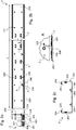
Une structure de paroi, par exemple pour réaliser un faux plafond, comprend au moins un assemblage 1 entre un profilé 2 et une entretoise 3.A wall structure, for example to make a false ceiling, comprises at least one assembly 1 between a
Le profilé 2 fait partie d'une ossature primaire de la structure. Il comporte une âme 200, présentant ici une semelle supérieure 201, et à sa base une semelle inférieure 202 formant appui.The
La semelle inférieure 202 comporte au moins une aile 203 formant un angle avec l'âme 200. En particulier, la semelle inférieure 202 présente ici deux ailes symétriques par rapport à l'âme 200, situées de part et d'autre de l'âme 200, ce qui assure une meilleure stabilité et un meilleur équilibre au profilé 2.The lower sole 202 comprises at least one
Chaque aile 203 présente une extrémité comprenant un retour 204, formé ici orthogonalement à l'aile 203. L'âme 200 et le retour 204 s'étendant depuis une même première face 209 de l'aile 203. En l'occurrence, le retour 204 présente en outre un ourlet 205 permettant de minimiser des risques de blessure d'un utilisateur par rapport à un bord brut par exemple. Un tel ourlet 205 contribue aussi à rigidifier le profilé 2.Each
Dans le présent exemple de réalisation, la semelle supérieure 201 présente une structure identique à la semelle inférieure 202, et elles sont de préférence formées orthogonalement à l'âme 200. Toutefois, la semelle supérieure 201 pourrait être dépourvue de retour 204 par exemple.In the present embodiment, the upper sole 201 has a structure identical to the lower sole 202, and they are preferably formed orthogonally to the
Le profilé 2 est ici composé de deux éléments ayant globalement une configuration en « C » mis dos à dos et reliés par clinchage ou rivets par exemple (ici par clinchage). Le profilé a ainsi ici une forme globalement en « I », ce qui lui confère par exemple une symétrie selon un plan passant entre les deux « C ».The
On entend par élément en « C », que chaque élément présente au moins une aile inférieure et une aile supérieure avec leur retour correspondant, ainsi qu'une partie de l'âme du profilé formant le dos du « C »."C" element is understood to mean that each element has at least one lower wing and one upper wing with their corresponding return, as well as a portion of the web of the profile forming the back of the "C".
Ainsi quand deux « C » sont positionnés dos à dos, les ailes inférieures forment la semelle inférieure 202 et les ailes supérieures forment la semelle supérieure 201, et les dos des « C » forment l'âme 200 du profilé 2.Thus when two "C" are positioned back to back, the lower wings form the lower sole 202 and the upper wings form the upper sole 201, and the backs of the "C" form the
Le clinchage, permettant par exemple l'assemblage des deux éléments, est de préférence réalisé après pliage des éléments en « C » pour ne pas solliciter mécaniquement les points de liaison.The clinching, allowing for example the assembly of the two elements, is preferably performed after folding elements "C" to not mechanically solicit the connection points.
Une alternative consisterait par exemple à réaliser le profilé 2 à partir d'une seule feuille d'acier (ou autre matériau) pliée et repliée sur elle-même.An alternative would be for example to make the
Selon le présent exemple de réalisation, une languette 206, 206', 206" apte à former une butée en translation est formée sur la même première face 209 de l'aile 203 que celle mentionnée précédemment, au moins sur la semelle inférieure 202.According to the present embodiment, a
La description qui suit est bien entendue valable pour un mode de réalisation de la présente invention dans lequel une (ou des) languette(s) sont formée(s) sur l'âme du profilé.The following description is of course valid for an embodiment of the present invention in which one (or) tab (s) are formed (s) on the web of the profile.
La languette 206, 206', 206" forme ainsi un moyen d'accrochage d'une entretoise 3 sur le profilé 2.The
Selon un exemple de réalisation, chaque aile du profilé 2 comprend au moins une languette 206, 206', 206".According to an exemplary embodiment, each wing of the
Et par exemple, au moins l'aile 203 comprend plusieurs languettes 206, 206', 206", voire toutes les ailes du profilé 2 comprennent plusieurs languettes 206, 206', 206".And for example, at least the
Une languette 206, 206', 206" est issue de l'aile 203 du profilé 2.A
Une languette 206, 206', 206" comprend une lame 210, 210', en attente, et reliée à l'aile 203 par une racine 207, 207', 207" sur laquelle vient s'empaler latéralement, jusqu'à venir en butée, une extrémité 301 d'une entretoise 3.A
En d'autres termes, une languette 206, 206', 206" est une pièce, sous forme de patte ou encore de doigt, réalisée par découpe de l'aile 203 et par pliage pour former une zone, une lame, 210, 210' globalement parallèle à l'aile 203 du côté de la face 209 grâce à une zone de raccordement à l'aile 203, la racine 207, 207', 207".In other words, a
Lorsque l'aile 203 présente au moins deux languettes 206, 206', 206" ou plus, les languettes 206, 206', 206" se présentent par exemple toutes dans un même sens, ou bien certaines des languettes peuvent se présenter en sens opposés, par exemple une languette sur deux.When the
Deux languettes en sens opposés sont par exemple représentées par les languettes 206 et 206', ou 206 et 206".Two tabs in opposite directions are for example represented by the
Selon un exemple de réalisation tel que représenté sur la
Inversement, une languette 206 est suffisamment éloignée d'une languette 206" qui lui fait face pour qu'une entretoise puisse être insérée. Deux languettes face à face sont par exemple représentées par les languettes 206 et 206" qui ne font alors pas partie d'une même paire.Conversely, a
Deux languettes consécutives, dans le même sens ou face à face, sont par exemple espacées l'une de l'autre de 100 mm, ou 200 mm, par exemple, offrant la possibilité de faire varier la répartition des entretoises 3.Two consecutive tongues, in the same direction or face to face, are for example spaced from each other by 100 mm, or 200 mm, for example, offering the possibility of varying the distribution of the
Selon un mode de réalisation, le profilé comprend aussi une ouïe de blocage 208. L'ouïe de blocage 208 est par exemple formée dans l'âme 200 du profilé 2, par exemple par découpe et emboutissage. Elle est positionnée de sorte qu'elle forme un appui pour un rebord 305 d'une entretoise 3 afin que l'entretoise 3 soit empêchée de s'écarter, se soulever, de l'aile 203 de la semelle inférieure 202 sur laquelle elle est montée.According to one embodiment, the profile also comprises a locking
Selon le présent exemple de réalisation, quand le profilé comprend des languettes 206, 206" en sens opposés, l'ouïe de blocage 208 est de préférence centrée par rapport à deux languettes 206, 206" face à face. Ainsi, une entretoise 3 peut indifféremment être bloquée sur une languette 206 ou une languette 206" tout en ayant un rebord 305 en appui sur l'ouïe de blocage 208, permettant ainsi d'éviter un échappement de l'entretoise 3 lors du vissage de plaques sur l'entretoise3. Une distance séparant une racine 207 d'une languette 206 d'une racine 207" d'une languette 206" lui faisant face est alors par exemple environ égale à deux fois une largeur (e) d'une entretoise 3.According to the present embodiment, when the profile comprises
A cet effet, une entretoise est amenée en position comme représenté par l'entretoise 3'. Elle est posée sur l'aile 203, et est translaté, glissée, d'un côté ou de l'autre (à gauche ou à droite) comme l'illustrent l'entretoise 3 (qui a été translatée à gauche) et l'entretoise 3" (qui a été translatée à droite).For this purpose, a spacer is brought into position as shown by the spacer 3 '. It is placed on the
Une fois des entretoises 3 en position sur des profilés 2, des plaques, par exemple en plâtre, sont vissées sur la structure ainsi obtenue.Once
Selon un autre exemple de réalisation représenté
Selon le mode de réalisation choisi, deux ouïes 208 consécutives sont par exemple espacées de 100 mm ou 200 mm, ou par exemple toutes les ouïes 208 d'un profilé 2 sont éloignées les unes des autres d'une même distance.According to the embodiment chosen, two
Dans le mode de réalisation de la
Ainsi, un profilé 2 peut présenter un, deux ou trois plans de symétrie selon le mode de réalisation envisagé. Par exemple, le mode de réalisation présenté
Pour assurer un tel assemblage 1, quel que soit le mode de réalisation du profilé 2, l'entretoise 3 présente principalement un corps 300 et une (généralement deux) extrémité 301 de montage.To ensure such an assembly 1, whatever the embodiment of the
Le corps 300 de l'entretoise 3 représente globalement une partie de l'entretoise 3 située entre deux profilés 2.The
Une entretoise 3 a, par exemple, une longueur entre deux profilés 2 (c'est-à-dire une longueur de corps) permettant une répartition de ces profilés 2 tous les 1,20 m ou 1,50 m.A
L'entretoise 3 se présente ici suivant une configuration globalement en « U », un fond 306 et deux flancs latéraux 304 présentent chacun un rebord 305 formé ici par une extrémité du flanc 304 repliée à angle droit.The
L'extrémité 301 de l'entretoise 3 présente également une découpe 303 ici sous forme d'une fente, pouvant être par exemple réalisée par grugeage. La découpe 303 s'étend ici d'un flanc 304 à l'autre et traverse en outre le fond 306 afin que l'entretoise 3 puisse venir en appui sur le retour 204 de l'aile 203 du profilé 2.The
L'extrémité 301 présente aussi ici une échancrure 307 qui est notamment utile si le profilé comprend une ouïe de blocage 208 (ou 208'), car elle permet alors de la contourner lorsque l'entretoise 3 est mise en position sur le profilé 2, comme l'illustre l'entretoise en position 3'. L'échancrure 307 est par exemple réalisée par grugeage.The
L'extrémité 301 présente en outre un passage latéral 302, une ouverture, dans lequel vient s'insérer une languette. Un passage 302 est également optionnellement réalisé par grugeage.The
Selon un exemple intéressant de réalisation, l'extrémité 301 comprend deux passages 302 formés dans chacun des flancs 304 pour permettre un accrochage de l'entretoise 3 sur une languette de chaque côté indifféremment.According to an interesting embodiment, the
Ainsi, l'entretoise 3 présente par exemple un plan, voire deux plans de symétrie. Dans les exemples de réalisation présentés ici, l'entretoise 3 présente alors au moins un plan de symétrie, voire de préférence deux plans de symétrie.Thus, the
Selon un exemple de réalisation intéressant, la lame 210, 210' d'une languette 206, 206', 206" présente une forme globalement ondulée, en forme de vague, de sorte à pouvoir produire un encliquetage, par exemple sur une bosse 308 formée sur le fond 306 de l'entretoise 3. Un tel encliquetage favorise un blocage de l'entretoise 3 sur le profilé 2.According to an interesting example of embodiment, the
Ainsi, les coopérations conjointes entre le retour 204 d'aile 203 et la découpe 303, entre une languette 206, 206', 206" et un passage 302, et entre un rebord 305 d'un flanc 304 d'entretoise 3 avec une ouïe de blocage 208 permettent un assemblage robuste minimisant des mouvements relatifs entre l'entretoise 3 et le profilé 2, avec un assemblage facile, rapide, et sécurisé.Thus, the joint cooperations between the
Plus précisément, l'ouïe de blocage 208 et la face 209 de l'aile 203 présentent une distance équivalente à une hauteur h de l'entretoise 3 pour que celle-ci soit bloquée en hauteur une fois en position, i.e. selon une direction orthogonale à l'aile 203. La coopération entre le retour 204 d'aile 203 et la découpe 303 permet un blocage selon une direction orthogonale à l'âme 200 et un guidage en translation le long du retour 204 d'aile 203. Et la coopération entre une languette 206, 206', 206" et son passage 302 permet un positionnement précis de l'entretoise 3 sur le profilé 2 permettant les blocages précédemment cités.More specifically, the locking
Ainsi un seul mouvement possible est celui selon une direction tendant à s'éloigner de la languette (vers son ouverture). Or, la structure assemblée ne subit généralement pas de sollicitation selon cette direction, sauf dans le cas d'une paroi verticale. Il est alors intéressant que le profilé 2 présente des languettes 206, 206', 206" en sens opposés afin que les entretoises 3 soient alors positionnées sur les languettes de sorte à venir naturellement en appui sur la racine 207, 207', 207" par gravité. Dans tous les cas, une sortie de l'entretoise 3 par rapport à la languette 206, 206', 206" peut être encore limitée, voire évitée, grâce à un encliquetage sur une bosse 308.Thus only one possible movement is that in a direction tending to move away from the tongue (towards its opening). However, the assembled structure does not generally undergo stress in this direction, except in the case of a vertical wall. It is then interesting that the
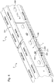
Enfin, en référence aux
L'éclisse 4 comporte une âme 400 présentant une surface active 403 depuis laquelle s'étendent une aile supérieure 401 et une aile inférieure 402. Dans l'exemple de réalisation de la
Dans le présent exemple de réalisation, lors de l'assemblage, par exemple par coulissement, l'âme 400 de l'éclisse 4 vient ainsi en appui contre l'âme 200 d'au moins un premier profilé 2, et l'aile inférieure 402 de l'éclisse 4 vient en appui contre la semelle inférieure 202 d'au moins le premier profilé 2 et l'aile supérieure 401 de l'éclisse 4 vient en appui contre la semelle supérieure 201 d'au moins le premier profilé 2.In the present embodiment, during assembly, for example by sliding, the
En outre, l'aile supérieure 401 et l'aile inférieure 402 de l'éclisse 4 sont alors chacune positionnées entre l'âme 200 d'au moins le premier profilé 2 et au moins une languette 206, 206', 206" formée sur une première face 209 d'une aile 203 de la semelle inférieure 202 et de la semelle supérieure 201 du profilé 2 (comme ceci est par exemple visible
L'âme 400 de l'éclisse 4 présente en outre ici des ouïes 408, 408' en relief sur la surface active 403 pour limiter un déplacement d'une entretoise 3 selon une direction orthogonale à l'aile 203 d'un des profilés 2 lorsque ceux-ci sont assemblés.The
En outre, pour placer l'éclisse 4 plus facilement en assurant un intervalle régulier entre les ouïes 408, 408' de l'éclisse 4 et 208, 208' des profilés 2, l'âme 400 de l'éclisse 4 comprend par exemple des passages 404, ici de forme oblongue, à positionner par exemple en vis-à-vis de points d'assemblage 211, par exemple de clinchage. On remarque par exemple que pour améliorer le positionnement de l'éclisse 4 telle que représentée
Enfin, la
Une telle éclisse 4 permet ainsi d'assurer une continuité entre deux profilés 2. En outre, une éclisse 4 est par exemple située de chaque côté de l'âme 200 du profilé 2 si nécessaire pour augmenter la rigidité et/ou la robustesse de la structure.Such a
Dans l'exemple de réalisation de la
Enfin, une telle éclisse 4 présente un trou 407 (par exemple de diamètre 6,2 mm), formé dans l'âme 400 prêt d'une extrémité, par exemple vers un milieu d'une hauteur de l'âme 400, c'est-à-dire à égales distances de l'aile supérieure 401 et de l'aile inférieure 402 par exemple. Un tel trou 407 permet par exemple un boulonnage dos-à-dos de deux éclisses 4 afin d'abouter deux profilés 2, non plus de manière linéaire, mais avec un angle réglable (ex : combles, plafonds à redents, etc.).Finally, such a
Une telle éclisse présente ainsi un seul plan de symétrie.Such a splint thus has a single plane of symmetry.
Ainsi, selon les besoins et les profilés 2 utilisés, l'éclisse 4 présente au choix une aile inférieure 402 et/ou une aile supérieure 401, l'aile inférieure 402 et l'aile supérieure 401 pouvant être de tailles identiques ou différentes si l'éclisse comporte à la fois l'aile inférieure 402 et l'aile supérieure 401, optionnellement au moins une ouïe 408 en partie inférieure, voire optionnellement au moins une ouïe 408' en partie supérieure, au moins une découpe 406, et si besoin au moins un passage 404.Thus, according to the needs and the
Bien entendu, de nombreuses modifications peuvent être apportées à l'exemple de réalisation décrit précédemment sans sortir du cadre de l'invention.Of course, many modifications can be made to the embodiment described above without departing from the scope of the invention.
Claims (8)
Applications Claiming Priority (3)
| Application Number | Priority Date | Filing Date | Title |
|---|---|---|---|
| FR1356402A FR3007777B1 (en) | 2013-07-01 | 2013-07-01 | PROFILE WITH RETURNS AND TABS AND ASSOCIATED SPACER |
| PCT/FR2014/051664 WO2015001237A2 (en) | 2013-07-01 | 2014-06-30 | Section having a lip and tongues, and associated spacer |
| EP14745192.6A EP3017121B1 (en) | 2013-07-01 | 2014-06-30 | Section having a lip and tongues, and associated spacer |
Related Parent Applications (2)
| Application Number | Title | Priority Date | Filing Date |
|---|---|---|---|
| EP14745192.6A Division EP3017121B1 (en) | 2013-07-01 | 2014-06-30 | Section having a lip and tongues, and associated spacer |
| EP14745192.6A Division-Into EP3017121B1 (en) | 2013-07-01 | 2014-06-30 | Section having a lip and tongues, and associated spacer |
Publications (2)
| Publication Number | Publication Date |
|---|---|
| EP3301238A1 true EP3301238A1 (en) | 2018-04-04 |
| EP3301238B1 EP3301238B1 (en) | 2019-04-10 |
Family
ID=49378428
Family Applications (2)
| Application Number | Title | Priority Date | Filing Date |
|---|---|---|---|
| EP17182697.7A Active EP3301238B1 (en) | 2013-07-01 | 2014-06-30 | Profile member with return and tabs and associated spacer |
| EP14745192.6A Active EP3017121B1 (en) | 2013-07-01 | 2014-06-30 | Section having a lip and tongues, and associated spacer |
Family Applications After (1)
| Application Number | Title | Priority Date | Filing Date |
|---|---|---|---|
| EP14745192.6A Active EP3017121B1 (en) | 2013-07-01 | 2014-06-30 | Section having a lip and tongues, and associated spacer |
Country Status (6)
| Country | Link |
|---|---|
| EP (2) | EP3301238B1 (en) |
| ES (2) | ES2733919T3 (en) |
| FR (1) | FR3007777B1 (en) |
| PT (2) | PT3017121T (en) |
| TW (1) | TW201522751A (en) |
| WO (1) | WO2015001237A2 (en) |
Cited By (2)
| Publication number | Priority date | Publication date | Assignee | Title |
|---|---|---|---|---|
| GB2583362A (en) * | 2019-04-25 | 2020-10-28 | Quicktrak Ltd | Partition support structure mounting track |
| GB2597863A (en) * | 2019-04-25 | 2022-02-09 | Quicktrak Ltd | Partition support structure mounting track |
Families Citing this family (1)
| Publication number | Priority date | Publication date | Assignee | Title |
|---|---|---|---|---|
| FR3040063B1 (en) * | 2015-08-10 | 2018-10-12 | Ets Leroux S A | PROFILES WITH REMOVABLE RECIPROCAL CONNECTING MEANS |
Citations (9)
| Publication number | Priority date | Publication date | Assignee | Title |
|---|---|---|---|---|
| GB1417689A (en) * | 1973-05-23 | 1975-12-17 | Reininghaus A | Suspended ceiling structures |
| US3989399A (en) * | 1974-10-04 | 1976-11-02 | Slowbe Joseph A | Structural joint assembly |
| US4047348A (en) * | 1976-06-28 | 1977-09-13 | Johns-Manville Corporation | Ceiling support grid system |
| DE2641667A1 (en) * | 1976-09-16 | 1978-03-23 | Beck Stahlbau Fertigbau H | Interlocking profiled false lengthwise or transverse ceiling beam - has fish-plates and notches in double bent sidewall flanges |
| US6729096B1 (en) * | 2002-09-09 | 2004-05-04 | Aaon Inc. | System for installing suspended ceiling |
| US20060010812A1 (en) * | 2004-07-14 | 2006-01-19 | Worthington Armstrong Venture | Molding for suspended panel ceiling |
| US20080229680A1 (en) * | 2007-03-21 | 2008-09-25 | Jahn Peter G | Wall angle with pre-punched locating tabs |
| US20080236068A1 (en) * | 2007-03-29 | 2008-10-02 | Jahn Peter G | Drywall channel with pre-punched locating tabs |
| FR2970012A1 (en) | 2011-01-04 | 2012-07-06 | Placoplatre Sa | Primary framework profile for false ceiling suspension on support structure e.g. floor, has lower sole comprising fixing heads that are projected from sole on side opposite to core to produce snap with C-shaped channel part |
Family Cites Families (1)
| Publication number | Priority date | Publication date | Assignee | Title |
|---|---|---|---|---|
| JP2000204711A (en) * | 1999-01-12 | 2000-07-25 | Showa Alum Corp | Ceiling reinforcing beam of built-up refrigerator |
-
2013
- 2013-07-01 FR FR1356402A patent/FR3007777B1/en active Active
-
2014
- 2014-06-30 WO PCT/FR2014/051664 patent/WO2015001237A2/en active Application Filing
- 2014-06-30 PT PT147451926T patent/PT3017121T/en unknown
- 2014-06-30 ES ES17182697T patent/ES2733919T3/en active Active
- 2014-06-30 EP EP17182697.7A patent/EP3301238B1/en active Active
- 2014-06-30 PT PT17182697T patent/PT3301238T/en unknown
- 2014-06-30 ES ES14745192T patent/ES2935921T3/en active Active
- 2014-06-30 EP EP14745192.6A patent/EP3017121B1/en active Active
- 2014-06-30 TW TW103122610A patent/TW201522751A/en unknown
Patent Citations (9)
| Publication number | Priority date | Publication date | Assignee | Title |
|---|---|---|---|---|
| GB1417689A (en) * | 1973-05-23 | 1975-12-17 | Reininghaus A | Suspended ceiling structures |
| US3989399A (en) * | 1974-10-04 | 1976-11-02 | Slowbe Joseph A | Structural joint assembly |
| US4047348A (en) * | 1976-06-28 | 1977-09-13 | Johns-Manville Corporation | Ceiling support grid system |
| DE2641667A1 (en) * | 1976-09-16 | 1978-03-23 | Beck Stahlbau Fertigbau H | Interlocking profiled false lengthwise or transverse ceiling beam - has fish-plates and notches in double bent sidewall flanges |
| US6729096B1 (en) * | 2002-09-09 | 2004-05-04 | Aaon Inc. | System for installing suspended ceiling |
| US20060010812A1 (en) * | 2004-07-14 | 2006-01-19 | Worthington Armstrong Venture | Molding for suspended panel ceiling |
| US20080229680A1 (en) * | 2007-03-21 | 2008-09-25 | Jahn Peter G | Wall angle with pre-punched locating tabs |
| US20080236068A1 (en) * | 2007-03-29 | 2008-10-02 | Jahn Peter G | Drywall channel with pre-punched locating tabs |
| FR2970012A1 (en) | 2011-01-04 | 2012-07-06 | Placoplatre Sa | Primary framework profile for false ceiling suspension on support structure e.g. floor, has lower sole comprising fixing heads that are projected from sole on side opposite to core to produce snap with C-shaped channel part |
Cited By (4)
| Publication number | Priority date | Publication date | Assignee | Title |
|---|---|---|---|---|
| GB2583362A (en) * | 2019-04-25 | 2020-10-28 | Quicktrak Ltd | Partition support structure mounting track |
| GB2583362B (en) * | 2019-04-25 | 2021-12-08 | Quicktrak Ltd | Partition support structure mounting track |
| GB2597863A (en) * | 2019-04-25 | 2022-02-09 | Quicktrak Ltd | Partition support structure mounting track |
| GB2597863B (en) * | 2019-04-25 | 2022-06-01 | Quicktrak Ltd | Partition support structure mounting track |
Also Published As
| Publication number | Publication date |
|---|---|
| FR3007777B1 (en) | 2016-01-01 |
| ES2935921T3 (en) | 2023-03-13 |
| TW201522751A (en) | 2015-06-16 |
| FR3007777A1 (en) | 2015-01-02 |
| EP3017121B1 (en) | 2022-10-26 |
| WO2015001237A3 (en) | 2015-03-05 |
| WO2015001237A2 (en) | 2015-01-08 |
| ES2733919T3 (en) | 2019-12-03 |
| EP3301238B1 (en) | 2019-04-10 |
| PT3301238T (en) | 2019-07-15 |
| PT3017121T (en) | 2023-01-27 |
| EP3017121A2 (en) | 2016-05-11 |
Similar Documents
| Publication | Publication Date | Title |
|---|---|---|
| FR2900219A1 (en) | Telescopic type flat connecting plate for e.g. high rise false ceiling construction, has detent unit forming angle in interior space with lateral walls having elastic deformability, where certain angle is formed between base and each wall | |
| EP3301238B1 (en) | Profile member with return and tabs and associated spacer | |
| FR3074206B1 (en) | RIGID GRID PANEL SLIDING FIXING DEVICE, RIGID GRID FIXING PANEL FIXING KIT, AND OCCULTANT CLOSURE EQUIPPED WITH SUCH A KIT | |
| FR2552474A1 (en) | GRID FOR CEILING SUSPENDED WITH NARROW VISIBLE FACE | |
| EP2458103B1 (en) | Ceiling panel system | |
| EP1099029A1 (en) | Safety wooden barrier supported on variable centrelines | |
| FR3083291A1 (en) | CONNECTION SYSTEM FOR ELEMENTS OF ELONGATE SHAPE | |
| EP0774032A1 (en) | Adjustable staircase | |
| EP1722111B1 (en) | Fastening device for fastening a metal profile on a support | |
| WO2016198777A1 (en) | Mounting fishplate for c-shaped profiles | |
| FR2922237A1 (en) | Fastener for suspending panel of suspended ceiling to ceiling wall, has plate hooked in suspension to lower free flange of I-shaped beam for anchoring board in metallic suspension section so that section is maintained in suspension at beam | |
| EP1617155B1 (en) | Ventilation grill | |
| FR3025503A1 (en) | CONSTRUCTION ASSEMBLY FOR ELEVATOR PYLON AND ELEVATOR PYLON | |
| EP0421905A1 (en) | Shelving arrangement | |
| EP1471207B1 (en) | Fixation system for lamellae and facade comprising such a system | |
| EP3555384B1 (en) | Attachment bracket for an insulating panel | |
| EP2453540B1 (en) | Universal support rail | |
| EP3748097A1 (en) | Metal frame for prefabricated drywall panels | |
| EP3372752B1 (en) | Anchoring assembly for anchoring through an opening a precut drywall portion | |
| FR3057886A1 (en) | FIXING SYSTEM, FACING ASSEMBLY OF AT LEAST TWO SUPERPOSED FIXING SYSTEMS, AND FENCE, PAREMENT AND FENCE COMPRISING AT LEAST ONE FACING ASSEMBLY | |
| EP3162973B1 (en) | Device for linking a suspended ceiling to a slab | |
| FR2757696A1 (en) | Horizontal bracket used to support trays for electrical cables, optical fibres | |
| FR2970017A1 (en) | Device for assembling step on stringer of height access structure used for single plane ladder, has opening for insertion of one of end portions of steps, and anti-rotation unit allowing anti-rotation of step on support | |
| EP2182127A1 (en) | Structure comprising a first and a second wall leaf, substantially vertical and spaced apart | |
| FR3010426A1 (en) | COUVERTINE HOOK |
Legal Events
| Date | Code | Title | Description |
|---|---|---|---|
| PUAI | Public reference made under article 153(3) epc to a published international application that has entered the european phase |
Free format text: ORIGINAL CODE: 0009012 |
|
| STAA | Information on the status of an ep patent application or granted ep patent |
Free format text: STATUS: THE APPLICATION HAS BEEN PUBLISHED |
|
| AC | Divisional application: reference to earlier application |
Ref document number: 3017121 Country of ref document: EP Kind code of ref document: P |
|
| AK | Designated contracting states |
Kind code of ref document: A1 Designated state(s): AL AT BE BG CH CY CZ DE DK EE ES FI FR GB GR HR HU IE IS IT LI LT LU LV MC MK MT NL NO PL PT RO RS SE SI SK SM TR |
|
| STAA | Information on the status of an ep patent application or granted ep patent |
Free format text: STATUS: REQUEST FOR EXAMINATION WAS MADE |
|
| 17P | Request for examination filed |
Effective date: 20180412 |
|
| RBV | Designated contracting states (corrected) |
Designated state(s): AL AT BE BG CH CY CZ DE DK EE ES FI FR GB GR HR HU IE IS IT LI LT LU LV MC MK MT NL NO PL PT RO RS SE SI SK SM TR |
|
| GRAP | Despatch of communication of intention to grant a patent |
Free format text: ORIGINAL CODE: EPIDOSNIGR1 |
|
| STAA | Information on the status of an ep patent application or granted ep patent |
Free format text: STATUS: GRANT OF PATENT IS INTENDED |
|
| INTG | Intention to grant announced |
Effective date: 20181205 |
|
| GRAS | Grant fee paid |
Free format text: ORIGINAL CODE: EPIDOSNIGR3 |
|
| GRAJ | Information related to disapproval of communication of intention to grant by the applicant or resumption of examination proceedings by the epo deleted |
Free format text: ORIGINAL CODE: EPIDOSDIGR1 |
|
| GRAL | Information related to payment of fee for publishing/printing deleted |
Free format text: ORIGINAL CODE: EPIDOSDIGR3 |
|
| STAA | Information on the status of an ep patent application or granted ep patent |
Free format text: STATUS: REQUEST FOR EXAMINATION WAS MADE |
|
| GRAR | Information related to intention to grant a patent recorded |
Free format text: ORIGINAL CODE: EPIDOSNIGR71 |
|
| STAA | Information on the status of an ep patent application or granted ep patent |
Free format text: STATUS: GRANT OF PATENT IS INTENDED |
|
| GRAA | (expected) grant |
Free format text: ORIGINAL CODE: 0009210 |
|
| STAA | Information on the status of an ep patent application or granted ep patent |
Free format text: STATUS: THE PATENT HAS BEEN GRANTED |
|
| INTC | Intention to grant announced (deleted) | ||
| INTG | Intention to grant announced |
Effective date: 20190228 |
|
| AC | Divisional application: reference to earlier application |
Ref document number: 3017121 Country of ref document: EP Kind code of ref document: P |
|
| AK | Designated contracting states |
Kind code of ref document: B1 Designated state(s): AL AT BE BG CH CY CZ DE DK EE ES FI FR GB GR HR HU IE IS IT LI LT LU LV MC MK MT NL NO PL PT RO RS SE SI SK SM TR |
|
| REG | Reference to a national code |
Ref country code: GB Ref legal event code: FG4D Free format text: NOT ENGLISH |
|
| REG | Reference to a national code |
Ref country code: CH Ref legal event code: EP Ref country code: AT Ref legal event code: REF Ref document number: 1118824 Country of ref document: AT Kind code of ref document: T Effective date: 20190415 |
|
| REG | Reference to a national code |
Ref country code: IE Ref legal event code: FG4D Free format text: LANGUAGE OF EP DOCUMENT: FRENCH |
|
| REG | Reference to a national code |
Ref country code: DE Ref legal event code: R096 Ref document number: 602014044741 Country of ref document: DE |
|
| REG | Reference to a national code |
Ref country code: PT Ref legal event code: SC4A Ref document number: 3301238 Country of ref document: PT Date of ref document: 20190715 Kind code of ref document: T Free format text: AVAILABILITY OF NATIONAL TRANSLATION Effective date: 20190704 |
|
| REG | Reference to a national code |
Ref country code: NL Ref legal event code: MP Effective date: 20190410 |
|
| REG | Reference to a national code |
Ref country code: LT Ref legal event code: MG4D |
|
| REG | Reference to a national code |
Ref country code: AT Ref legal event code: MK05 Ref document number: 1118824 Country of ref document: AT Kind code of ref document: T Effective date: 20190410 |
|
| PG25 | Lapsed in a contracting state [announced via postgrant information from national office to epo] |
Ref country code: NL Free format text: LAPSE BECAUSE OF FAILURE TO SUBMIT A TRANSLATION OF THE DESCRIPTION OR TO PAY THE FEE WITHIN THE PRESCRIBED TIME-LIMIT Effective date: 20190410 |
|
| PG25 | Lapsed in a contracting state [announced via postgrant information from national office to epo] |
Ref country code: SE Free format text: LAPSE BECAUSE OF FAILURE TO SUBMIT A TRANSLATION OF THE DESCRIPTION OR TO PAY THE FEE WITHIN THE PRESCRIBED TIME-LIMIT Effective date: 20190410 Ref country code: HR Free format text: LAPSE BECAUSE OF FAILURE TO SUBMIT A TRANSLATION OF THE DESCRIPTION OR TO PAY THE FEE WITHIN THE PRESCRIBED TIME-LIMIT Effective date: 20190410 Ref country code: AL Free format text: LAPSE BECAUSE OF FAILURE TO SUBMIT A TRANSLATION OF THE DESCRIPTION OR TO PAY THE FEE WITHIN THE PRESCRIBED TIME-LIMIT Effective date: 20190410 Ref country code: FI Free format text: LAPSE BECAUSE OF FAILURE TO SUBMIT A TRANSLATION OF THE DESCRIPTION OR TO PAY THE FEE WITHIN THE PRESCRIBED TIME-LIMIT Effective date: 20190410 Ref country code: NO Free format text: LAPSE BECAUSE OF FAILURE TO SUBMIT A TRANSLATION OF THE DESCRIPTION OR TO PAY THE FEE WITHIN THE PRESCRIBED TIME-LIMIT Effective date: 20190710 Ref country code: LT Free format text: LAPSE BECAUSE OF FAILURE TO SUBMIT A TRANSLATION OF THE DESCRIPTION OR TO PAY THE FEE WITHIN THE PRESCRIBED TIME-LIMIT Effective date: 20190410 |
|
| PG25 | Lapsed in a contracting state [announced via postgrant information from national office to epo] |
Ref country code: GR Free format text: LAPSE BECAUSE OF FAILURE TO SUBMIT A TRANSLATION OF THE DESCRIPTION OR TO PAY THE FEE WITHIN THE PRESCRIBED TIME-LIMIT Effective date: 20190711 Ref country code: BG Free format text: LAPSE BECAUSE OF FAILURE TO SUBMIT A TRANSLATION OF THE DESCRIPTION OR TO PAY THE FEE WITHIN THE PRESCRIBED TIME-LIMIT Effective date: 20190710 Ref country code: RS Free format text: LAPSE BECAUSE OF FAILURE TO SUBMIT A TRANSLATION OF THE DESCRIPTION OR TO PAY THE FEE WITHIN THE PRESCRIBED TIME-LIMIT Effective date: 20190410 Ref country code: LV Free format text: LAPSE BECAUSE OF FAILURE TO SUBMIT A TRANSLATION OF THE DESCRIPTION OR TO PAY THE FEE WITHIN THE PRESCRIBED TIME-LIMIT Effective date: 20190410 Ref country code: PL Free format text: LAPSE BECAUSE OF FAILURE TO SUBMIT A TRANSLATION OF THE DESCRIPTION OR TO PAY THE FEE WITHIN THE PRESCRIBED TIME-LIMIT Effective date: 20190410 |
|
| REG | Reference to a national code |
Ref country code: ES Ref legal event code: FG2A Ref document number: 2733919 Country of ref document: ES Kind code of ref document: T3 Effective date: 20191203 |
|
| PG25 | Lapsed in a contracting state [announced via postgrant information from national office to epo] |
Ref country code: AT Free format text: LAPSE BECAUSE OF FAILURE TO SUBMIT A TRANSLATION OF THE DESCRIPTION OR TO PAY THE FEE WITHIN THE PRESCRIBED TIME-LIMIT Effective date: 20190410 Ref country code: IS Free format text: LAPSE BECAUSE OF FAILURE TO SUBMIT A TRANSLATION OF THE DESCRIPTION OR TO PAY THE FEE WITHIN THE PRESCRIBED TIME-LIMIT Effective date: 20190810 |
|
| REG | Reference to a national code |
Ref country code: DE Ref legal event code: R097 Ref document number: 602014044741 Country of ref document: DE |
|
| PG25 | Lapsed in a contracting state [announced via postgrant information from national office to epo] |
Ref country code: EE Free format text: LAPSE BECAUSE OF FAILURE TO SUBMIT A TRANSLATION OF THE DESCRIPTION OR TO PAY THE FEE WITHIN THE PRESCRIBED TIME-LIMIT Effective date: 20190410 Ref country code: DK Free format text: LAPSE BECAUSE OF FAILURE TO SUBMIT A TRANSLATION OF THE DESCRIPTION OR TO PAY THE FEE WITHIN THE PRESCRIBED TIME-LIMIT Effective date: 20190410 Ref country code: CZ Free format text: LAPSE BECAUSE OF FAILURE TO SUBMIT A TRANSLATION OF THE DESCRIPTION OR TO PAY THE FEE WITHIN THE PRESCRIBED TIME-LIMIT Effective date: 20190410 Ref country code: RO Free format text: LAPSE BECAUSE OF FAILURE TO SUBMIT A TRANSLATION OF THE DESCRIPTION OR TO PAY THE FEE WITHIN THE PRESCRIBED TIME-LIMIT Effective date: 20190410 Ref country code: SK Free format text: LAPSE BECAUSE OF FAILURE TO SUBMIT A TRANSLATION OF THE DESCRIPTION OR TO PAY THE FEE WITHIN THE PRESCRIBED TIME-LIMIT Effective date: 20190410 Ref country code: MC Free format text: LAPSE BECAUSE OF FAILURE TO SUBMIT A TRANSLATION OF THE DESCRIPTION OR TO PAY THE FEE WITHIN THE PRESCRIBED TIME-LIMIT Effective date: 20190410 |
|
| REG | Reference to a national code |
Ref country code: CH Ref legal event code: PL |
|
| PLBE | No opposition filed within time limit |
Free format text: ORIGINAL CODE: 0009261 |
|
| STAA | Information on the status of an ep patent application or granted ep patent |
Free format text: STATUS: NO OPPOSITION FILED WITHIN TIME LIMIT |
|
| PG25 | Lapsed in a contracting state [announced via postgrant information from national office to epo] |
Ref country code: SM Free format text: LAPSE BECAUSE OF FAILURE TO SUBMIT A TRANSLATION OF THE DESCRIPTION OR TO PAY THE FEE WITHIN THE PRESCRIBED TIME-LIMIT Effective date: 20190410 Ref country code: IT Free format text: LAPSE BECAUSE OF FAILURE TO SUBMIT A TRANSLATION OF THE DESCRIPTION OR TO PAY THE FEE WITHIN THE PRESCRIBED TIME-LIMIT Effective date: 20190410 |
|
| 26N | No opposition filed |
Effective date: 20200113 |
|
| REG | Reference to a national code |
Ref country code: BE Ref legal event code: MM Effective date: 20190630 |
|
| PG25 | Lapsed in a contracting state [announced via postgrant information from national office to epo] |
Ref country code: TR Free format text: LAPSE BECAUSE OF FAILURE TO SUBMIT A TRANSLATION OF THE DESCRIPTION OR TO PAY THE FEE WITHIN THE PRESCRIBED TIME-LIMIT Effective date: 20190410 |
|
| PG25 | Lapsed in a contracting state [announced via postgrant information from national office to epo] |
Ref country code: IE Free format text: LAPSE BECAUSE OF NON-PAYMENT OF DUE FEES Effective date: 20190630 |
|
| PG25 | Lapsed in a contracting state [announced via postgrant information from national office to epo] |
Ref country code: LU Free format text: LAPSE BECAUSE OF NON-PAYMENT OF DUE FEES Effective date: 20190630 Ref country code: CH Free format text: LAPSE BECAUSE OF NON-PAYMENT OF DUE FEES Effective date: 20190630 Ref country code: LI Free format text: LAPSE BECAUSE OF NON-PAYMENT OF DUE FEES Effective date: 20190630 Ref country code: SI Free format text: LAPSE BECAUSE OF FAILURE TO SUBMIT A TRANSLATION OF THE DESCRIPTION OR TO PAY THE FEE WITHIN THE PRESCRIBED TIME-LIMIT Effective date: 20190410 Ref country code: BE Free format text: LAPSE BECAUSE OF NON-PAYMENT OF DUE FEES Effective date: 20190630 |
|
| PG25 | Lapsed in a contracting state [announced via postgrant information from national office to epo] |
Ref country code: CY Free format text: LAPSE BECAUSE OF FAILURE TO SUBMIT A TRANSLATION OF THE DESCRIPTION OR TO PAY THE FEE WITHIN THE PRESCRIBED TIME-LIMIT Effective date: 20190410 |
|
| PG25 | Lapsed in a contracting state [announced via postgrant information from national office to epo] |
Ref country code: HU Free format text: LAPSE BECAUSE OF FAILURE TO SUBMIT A TRANSLATION OF THE DESCRIPTION OR TO PAY THE FEE WITHIN THE PRESCRIBED TIME-LIMIT; INVALID AB INITIO Effective date: 20140630 Ref country code: MT Free format text: LAPSE BECAUSE OF FAILURE TO SUBMIT A TRANSLATION OF THE DESCRIPTION OR TO PAY THE FEE WITHIN THE PRESCRIBED TIME-LIMIT Effective date: 20190410 |
|
| PG25 | Lapsed in a contracting state [announced via postgrant information from national office to epo] |
Ref country code: MK Free format text: LAPSE BECAUSE OF FAILURE TO SUBMIT A TRANSLATION OF THE DESCRIPTION OR TO PAY THE FEE WITHIN THE PRESCRIBED TIME-LIMIT Effective date: 20190410 |
|
| PGFP | Annual fee paid to national office [announced via postgrant information from national office to epo] |
Ref country code: PT Payment date: 20230628 Year of fee payment: 10 Ref country code: FR Payment date: 20230510 Year of fee payment: 10 Ref country code: DE Payment date: 20230502 Year of fee payment: 10 |
|
| PGFP | Annual fee paid to national office [announced via postgrant information from national office to epo] |
Ref country code: GB Payment date: 20230511 Year of fee payment: 10 Ref country code: ES Payment date: 20230707 Year of fee payment: 10 |