EP3301234A1 - Flush toilet - Google Patents
Flush toilet Download PDFInfo
- Publication number
- EP3301234A1 EP3301234A1 EP17189341.5A EP17189341A EP3301234A1 EP 3301234 A1 EP3301234 A1 EP 3301234A1 EP 17189341 A EP17189341 A EP 17189341A EP 3301234 A1 EP3301234 A1 EP 3301234A1
- Authority
- EP
- European Patent Office
- Prior art keywords
- flush water
- flush
- receiving surface
- well
- waste receiving
- Prior art date
- Legal status (The legal status is an assumption and is not a legal conclusion. Google has not performed a legal analysis and makes no representation as to the accuracy of the status listed.)
- Granted
Links
Images




Classifications
-
- E—FIXED CONSTRUCTIONS
- E03—WATER SUPPLY; SEWERAGE
- E03D—WATER-CLOSETS OR URINALS WITH FLUSHING DEVICES; FLUSHING VALVES THEREFOR
- E03D11/00—Other component parts of water-closets, e.g. noise-reducing means in the flushing system, flushing pipes mounted in the bowl, seals for the bowl outlet, devices preventing overflow of the bowl contents; devices forming a water seal in the bowl after flushing, devices eliminating obstructions in the bowl outlet or preventing backflow of water and excrements from the waterpipe
- E03D11/02—Water-closet bowls ; Bowls with a double odour seal optionally with provisions for a good siphonic action; siphons as part of the bowl
- E03D11/08—Bowls with means producing a flushing water swirl
-
- E—FIXED CONSTRUCTIONS
- E03—WATER SUPPLY; SEWERAGE
- E03D—WATER-CLOSETS OR URINALS WITH FLUSHING DEVICES; FLUSHING VALVES THEREFOR
- E03D2201/00—Details and methods of use for water closets and urinals not otherwise provided for
- E03D2201/30—Water injection in siphon for enhancing flushing
-
- E—FIXED CONSTRUCTIONS
- E03—WATER SUPPLY; SEWERAGE
- E03D—WATER-CLOSETS OR URINALS WITH FLUSHING DEVICES; FLUSHING VALVES THEREFOR
- E03D2201/00—Details and methods of use for water closets and urinals not otherwise provided for
- E03D2201/40—Devices for distribution of flush water inside the bowl
Definitions
- the present invention pertains to a flush toilet, and more particularly to a flush toilet in which flush water flushes the toilet and discharges waste.
- Patent Document 1 A flush toilet is described in Japanese Patent 3818834 (Patent Document 1).
- a horizontal circulating flow is induced by the discharge of flush water in the horizontal direction from a rim spout port disposed on the top edge of the bowl portion which receives waste, and the entire bowl surface is flushed by this circulating flow.
- Patent Document 2 There is also a flush toilet set forth in Japanese Published Unexamined Patent Application 2015-196960 (Patent Document 2).
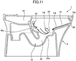
- a horizontal circulating flow is induced by the discharge of flush water in the horizontal direction from a rim spout port disposed on the top edge of the bowl portion which receives waste, and the entire bowl surface is flushed by this circulating flow.
- a guiding portion for directing the flow of flush water circulating in the bowl portion to flow toward the bottom surface of the bowl portion is disposed in the rear region of the bowl portion, and this guiding portion forms a flow for stirring accumulated water inside the bowl portion in the up-down direction.
- a guide portion is provided to produce a flow for stirring accumulated water in the up-down direction, enabling a submerging effect on waste floating in the accumulated water.
- flush water which has circulated over the bowl surface as a linear flow from a rim spout port is caused by the guide portion to flow into the accumulated water, therefore a horizontal circulating component remains as before in the flush water, and the ability to stir accumulated water in the up-down direction is poor.
- the water force of flush water which has circulated over the bowl surface is weak even if made to flow into the accumulated water by the guide portion, and its ability to stir accumulated water is insufficient.
- the present invention was undertaken to resolve the above problems, and has the object of providing a flush toilet capable of effectively discharging waste floating in accumulated water.
- the present invention is a flush toilet flushed by flush water and discharging waste, comprising: a bowl portion including a bowl-shaped waste receiving surface, a rim portion formed on an upper portion of the waste receiving surface, and a well portion formed below the waste receiving surface for storing an accumulated water; a discharge trap pipe connected so as to communicate with a bottom portion of the well portion, thereby discharging the flush water and the waste; a flush water guide portion formed on the waste receiving surface at a rear of the well portion so that the flush water supplied to the bowl portion is guided toward a side wall surface on an inside of the well portion; and a liquid membrane spouting portion formed on the rim portion; wherein the liquid membrane spouting portion discharges the flush water in a liquid membrane form so that the discharged flush water collides with the flush water guide portion to induce a vertical circulating flow in the accumulated water of the well portion, by dropping the flush water along the side wall surface of the well portion.
- flush water is discharged from the liquid membrane spouting portion disposed on the rim portion formed on the top portion of the waste receiving surface; the discharged flush water assumes a liquid membrane form and collides with the flush water guide portion, and the colliding flush water drops along the side wall surface of the well portion.
- the dropping of flush water along the side wall portion of the well portion induces a vertical circulating flow in the accumulated water in the well portion; waste floating in the accumulated water is submerged into the accumulated water in the well portion and discharged together with flush water from the trap conduit connected to the bottom portion of the well portion.
- flush water discharged from the liquid membrane spouting portion a liquid membrane form collides with the flush water guide portion and drops into the well portion, inducing a vertical circulating flow in the accumulated water, therefore waste floating in the accumulated water can be efficiently submerged in the accumulated water, and floating waste can be effectively discharged from the bowl portion.
- the flush water guide portion is a stepped portion formed on the waste receiving surface so as to be smoothly continuous with a ridge line of the well portion.
- the flush water guide portion is constituted by a stepped portion smoothly connected to the well portion ridge line, therefore flush water colliding with the flush water guide portion can be efficiently made to flow into the well portion, and a strong vertical circulating flow can be induced in the well portion without significant loss of force in the flush water discharged from the liquid membrane spouting portion. Waste floating in the accumulated water can thus be efficiently submerged and discharged.
- the flush water guide portion is configured such that a slope of the stepped portion in a circumferential direction of the waste receiving surface is most gradual in an outermost circumference of the waste receiving surface, and becomes steep as it approaches the well portion.
- the slope of the stepped portion forming the flush water guide portion is most gradual at the outermost circumference of the water reservoir and becomes steeper approaching the well portion, therefore the flush water in a liquid membrane state colliding with the flush water guide portion can be made to retain that shape as it flows into the well portion, and a stronger vertical circulating flow can be induced in the accumulated water within the well portion.
- the flush water guide portion is configured such that a step difference of the stepped portion is smallest at the outermost circumference of the waste receiving surface, and is largest approaching the well portion.
- the step difference of the stepped portion forming the flush water guide portion is smallest at the outermost circumference of the waste receiving surface and is made to increase toward the well portion, so the majority of flush water colliding with the flush water guide portion can be directed to the well portion, and a strong vertical circulating flow can be induced in the accumulated water in the well portion.
- the waste receiving surface has a concave portion which is formed in a rear portion of the waste receiving surface and is connected to the well portion, and one of end portions of the concave portion functions as the flush water guide portion on which the flush water collides.
- a concave portion connecting with the well portion is formed at the rear portion of the waste receiving surface, and one of the edge portions on this concave portion functions as a flush water guide portion, so that flush water colliding with the flush water guide portion immediately drops into the concave portion and flows into the well portion connected to the concave portion. Therefore the majority of flush water discharged as a liquid membrane from the liquid membrane spouting portion can be made to flow into the well portion over a relatively short path, and a strong vertical circulating flow can be induced in the well portion. Waste floating in the accumulated water can thus be efficiently submerged and discharged.
- the concave portion formed in the waste receiving surface lies from the well portion of the bowl portion to a rear end of the bowl portion.
- a concave portion is formed from the well portion to the rear edge of the bowl portion, therefore flush water flowing along the rear edge of the bowl portion collides with one edge portion of the concave portion (the flush water guide portion) and drops into the concave portion.
- the majority of flush water discharged as a liquid membrane from the liquid membrane spouting portion can be made to flow into the well portion by the flush water guide portion, and a strong vertical circulating flow can be induced in the well portion. Waste floating in the accumulated water can thus be efficiently submerged and discharged.
- the concave portion formed in the waste receiving surface has approximately a fan shape, broadening toward the rear of the bowl portion.
- the indentation is formed in essentially a fan shape widening toward the rear of the bowl portion, therefore the majority of flush water discharged in a liquid membrane state from the liquid membrane spouting portion and flowing to the rear portion of the bowl portion can be collected at the center of the indented portion, and the collected flush water can be made to flow in a concentrated manner into the well portion.
- a vertical circulating flow can be induced in the well portion, and waste floating in the accumulated water can be submerged and discharged.
- the liquid membrane spouting portion forms the flush water into the liquid membrane form by discharging the supplied flush water to follow a downward sloped surface descending downward in the direction of the flush water discharged from the liquid membrane spouting portion.
- the liquid membrane spouting portion forms flush water into a liquid membrane shape by discharging it along a downward sloped surface descending in the direction of flush water discharge, therefore discharged flush water can be efficiently placed into a liquid membrane form.
- Liquid membrane-shaped flush water is capable of inducing a strong vertical circulating flow upon flowing into the well portion, so that waste floating in the accumulated water can be submerged and discharged.
- the liquid membrane spouting portion is disposed at the rear of the bowl portion so as to oppose the flush water guide portion.
- the liquid membrane spouting portion is disposed at the rear of the bowl portion so as to oppose the flush water guide portion, therefore flush water discharged from the liquid membrane spouting portion collides with the flush water guide portion at close range. Flush water discharged from the liquid membrane spouting portion therefore flows into the well portion with the strong discharge force essentially maintained. As a result, a vertical circulating flow can be induced in the well portion, and waste floating in the accumulated water can be submerged and discharged.
- the liquid membrane spouting portion is disposed on the inside of a region in which the concave portion of the waste receiving surface is formed.
- the liquid membrane spouting portion is disposed on the inside of the region in which the concave portion of the waste receiving surface is formed, therefore the majority of flush water discharged from the liquid membrane spouting portion can be dropped into the concave portion, and flush water which has fallen into the concave portion can be made to flow into the well portion by the guide portion.
- a large volume of flush water can thus be made to flow into the well portion at once, so that a strong vertical circulating flow is induced in the well portion, and waste floating in the accumulated water can be efficiently submerged and discharged.
- rim spout portion disposed on the rim portion, wherein the rim spout portion discharges the flush water to form a horizontal circulating flow on the waste receiving surface.
- a rim spout portion forming a circulating flow in the horizontal direction on the waste receiving surface using discharged flush water is provided separately from the liquid membrane spouting portion, therefore waste adhering to the waste receiving surface can be effectively washed off, and the entire bowl portion can be effectively flushed.
- FIG. 1 is a plan view cross section showing a flush toilet according to an embodiment of the present invention
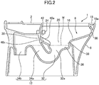
- Fig. 2 is a cross section seen along line II-II in Fig. 1 .
- the flush toilet 1 of the present embodiment is a wash-down type of toilet in which waste is pushed out by the flow action resulting from the water drop within the bowl portion, and comprises a toilet main body 2; flush water is introduced into this toilet main body 2 via a reservoir tank (not shown) serving as the flush water source.
- the toilet main body 2 is made of glazed ceramic; a skirt portion 6 is formed on the bottom portion thereof, and a bowl portion 8 is formed at the front on the upper half thereof.
- a shared water passageway 10 connected to a discharge port on the reservoir tank (not shown) is formed at the rear upper portion of the bowl portion 8; in addition, a discharge trap pipe 12 for discharging waste is formed at the rear lower portion of the bowl portion 8.
- the present invention without limitation to flush toilets comprising reservoir tanks, can also be applied to flush toilet in which flush water is supplied using a jet pump mechanism, or direct pressure-type flush toilets in which flush water is directly supplied.
- the bowl portion 8 comprises a bowl-shaped waste receiving surface 16, a rim portion 18 positioned on the top edge thereof, and a well portion 20, formed below the waste receiving surface 16.
- the rim portion 18 inside circumferential surface 18a has an overhanging shape toward the inside, so that flush water circulating in the horizontal direction, described below, does not splash to the outside.
- a first rim spout port 22 is formed at the center portion on the left side as seen from the front of the inside circumferential surface of the bowl portion 8 rim portion 18, and a second rim spout port 24, being a liquid membrane spouting portion, is formed on the right rear side (downstream side) as seen from the front thereof.
- This first rim spout port 22 and second rim spout port 24 are oriented so as to discharge flush water in the same direction on a horizontal plane (the counterclockwise direction in Fig. 1 ), and flush water discharged from the first rim spout port 22 forms a circulating flow circulating in the horizontal direction on the waste receiving surface 16.
- the shared water passageway 10 formed on the rear upper portion of the flush toilet 1 described above branches into a second water passageway 28 for supplying flush water to the first rim spout port 22 and a second water passageway 28 for supplying flush water to the second rim spout port 24.
- the first water passageway 26 including the first rim spout port 22, and the second water passageway 28 including the second rim spout port 24 are formed integrally with the ceramic toilet main body 2, but the present invention is not limited to such forms, and the present invention may also be formed by a distributor or the like separate from a first water passageway including the first rim spout port and a second water passageway including the second rim spout port.
- a shelf-shaped water conduit 30 for guiding flush water is formed in the bottom region of the inside circumferential surface 18a of the bowl portion 8 rim portion 18. Note that this water conduit 30 is also the external circumferential edge region of the waste receiving surface 16. The water conduit 30 causes flush water spouted from the first rim spout port 22 to circulate along the rim portion 18 inside circumferential surface 18a to the rear end portion of the waste receiving surface 16.
- a discharge trap pipe 12 is formed by an introducing pipe 32 connected to the well portion 20 bottom surface 36 and extending rearward and downward, and by an ascending pipe path 34a and a descending pipe path 34b.
- This introducing pipe 32 is connected as a smooth continuous curved surface to the bottom surface 36 of the well portion 20, and is arranged so that flush water flowing into the introducing pipe 32 from the well portion 20 flows smoothly inside the introducing pipe 32.
- the bowl portion 8 well portion 20 comprises a bottom surface 36 positioned below the accumulated water level W, and a side wall surface 38 for connecting this bottom surface 36 with the bottom edge portion of the waste receiving surface 16.
- This bottom surface 36 is formed in a region in front of the introducing pipe 32 inlet 32a, and is formed to be approximately horizontal. This bottom surface 36 may also be sloped downward toward the rear.
- no bottom surface 36 is formed, but a side wall surface 38 is formed; this side wall surface 38 is formed continuously with the introducing pipe 32 inlet 32a.
- an approximately fan-shaped concave portion 40 widening toward the rear of the bowl portion 8, is formed in the region at the rear portion of the waste receiving surface 16 between the 20 and the rear end portion of the bowl portion 8 (the rear edge portion of the waste receiving surface 16), so as to connect with the well portion 20.
- stepped portions 40a, 40b are respectively formed at both ends of the concave portion 40, and these stepped portions 40a, 40b smoothly continue the ridge line of the well portion 20.
- the second rim spout port 24 is disposed on the rear right side of the bowl portion 8 as seen from the front of the flush toilet 1, and discharges flush water to the left, therefore of the concave portion 40 stepped portions 40a, 40b, the stepped portion 40b (in this embodiment, the left side stepped portion) is oriented so as to face the second rim spout port 24. Therefore in the present embodiment the stepped portion 40b, oriented so as to face the second rim spout port 24, functions as a flush water guide portion so that flush water discharged from the second rim spout port 24 collides with it, and colliding flush water is made to drop down along the side wall surface 38 of the well portion 20.
- the stepped portion 40b is formed so that its angle increases toward the well portion and becomes deeper, so that when guiding a flush, spout water can be directed in a liquid membrane form toward the well portion.
- flush water colliding with the flush water guide portion (stepped portion 40b) and dropping along the 20 side wall surface 38 induces a vertical circulating flow.
- the minimum distance between the second rim spout port 24 and the left side stepped portion 40b is approximately 160 mm, and preferably between approximately 130 mm and approximately 200 mm.
- Fig. 3 is a perspective view showing the state whereby the flush toilet 1 is cut along a vertical plane extending in the left-right direction thereof.
- Figs. 4 through 8 are cross sections in which the flush toilet 1 is cut along lines IV-IV through lines VIII-VII in Fig. 1 .
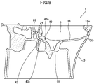
- Fig. 9 is a cross section cut through the flush toilet 1 along line IX-IX in Fig. 1 .
- the stepped portions 40a, 40b on both sides, formed by disposing the concave portion 40 on the waste receiving surface 16, are smoothly continuous with the side portion ridge lines 20a, 20b (the lines in which the side wall surfaces 38 on both side portions of the well portion 20 and the inside circumference of the waste receiving surface 16 intersect).
- the well portion 20 rear side top edge and the concave portion 40 bottom surface 40c also smoothly intersect, forming a rear portion ridge line 20c on the rear side of the well portion 20.
- the ridge in the left-right direction of the concave portion 40 is narrowest on the rear portion ridge line 20c of the well portion 20, widening toward the rear, and is widest at the rear end portion of the waste receiving surface 16.
- the gap in the left-right direction between the stepped portions 40a and 40b is greatest at the rear end portion, and is smallest at the connecting portion between the side portion ridge lines 20a, 20b of the toilet main body 2.
- the bottom surface 40c of the concave portion 40 is sloped so as to drop from the waste receiving surface 16 rear end portion toward the well portion 20, and the depth of the concave portion 40 is shallowest at the rear end portion of the waste receiving surface 16 and deepest at the rear portion ridge line 20c of the well portion 20.
- the stepped portions 40a, 40b have the smallest step difference (level difference) at the rear end portion of the waste receiving surface 16 (the outermost circumference of the waste receiving surface 16), and the step difference increases approaching the well portion 20.
- the width at the front end portion of the 40 (the part connecting with the well portion 20) is approximately 115 mm, and is formed to be approximately the same as the maximum width of the well portion 20.
- the rear end portion of the concave portion 40 (the part contacting the rim portion 18 inside circumferential surface 18a) is approximately 195 mm.
- the width at the rear end portion of the concave portion is formed to be approximately 100 mm to 240 mm, and the concave portion is formed with a center angle relative to the center of the well portion of between approximately 38° and approximately 110°.
- the depth of the concave portion 40 is formed to be approximately 18 mm at the deepest portion, and preferably the depth at the deepest portion is approximately 10 mm to 30 mm.
- the sloped surface angle in the left-right direction of the sloped surface facing from the concave portion 40 stepped portions 40a, 40b toward the bottom surface 40c is most gradual in the rear end portion of the waste receiving surface 16 (the outermost circumference of the waste receiving surface 16), and the slope gradually steepens approaching the well portion 20.
- the left-right direction slope of the sloped surface connecting the waste receiving surface 16 and the concave portion 40 bottom surface 40c is most gradual in the rear end portion of the waste receiving surface 16 ( Fig.
- the slope angle of the slope in the left-right direction heading from the stepped portion 40b to the bottom surface 40c is formed to be approximately 15° at its maximum, and the maximum slope angle is preferably approximately 5° to approximately 20°.
- first rim spout port 22 being a rim spout portion
- second rim spout port 24 being a liquid membrane spouting portion
- the first rim spout port 22 being a rim spout portion, is disposed on the left side portion of the bowl portion 8, and flush water discharged from the first rim spout port 22 is directed by a water conduit 30 provided on the outside circumferential portion of the waste receiving surface 16.
- the floor of the first rim spout port 22 and the outer surface of the water conduit 30 are generally continuous, and flush water discharged from the first rim spout port 22 is placed on the approximately horizontally formed water conduit 30 to be guided.
- Flush water guided along the water conduit 30 flows down a little at a time over the waste receiving surface 16, forming a counterclockwise horizontal circulating flow on the waste receiving surface 16, flowing into the well portion 20, thereby flushing the waste receiving surface 16.
- the second rim spout port 24 being a liquid membrane spouting portion, is formed on the inside of the region in which a concave portion is disposed at the right rear end portion of the bowl portion 8, as shown in Fig. 3 .
- the bottom surface of the second water passageway 28 is a downward slope from the vicinity of the second rim spout port 24 toward the discharge direction, and this sloped surface is smoothly continuous with the concave portion 40 bottom surface 40c, forming a downward sloped surface 42 toward the well portion 20.
- flush water discharged from the first rim spout port 22 is guided by the approximately horizontal water conduit 30, which is essentially continuous with the floor of the first rim spout port 22, no approximately horizontal guide path continuous with the floor is provided on the second rim spout port 24, and flush water from the second rim spout port 24 is discharged along the downward sloped surface 42, which is essentially continuous with the floor of the second rim spout port 24, and slopes downward toward the direction in which flush water is discharged.
- flush water discharged along the approximately horizontal water conduit 30 from the first rim spout port 22 flows as a liquid membrane on the water conduit 30, and rather than flowing down a little at a time on the waste receiving surface 16, the flush water discharged from the second rim spout port 24 to the downward sloped surface 42 assumes a liquid membrane form and flows diagonally downward from the second rim spout port 24.
- the slope in the direction spouted from the second rim spout port 24 (the circumferential direction of the waste receiving surface 16) forms the discharged flush water into a liquid membrane form by discharging it along the downward sloped surface 42 at an approximately 13° slope angle.
- flush water can be formed into a liquid membrane by discharging flush water along a downward sloped surface at a slope angle of 5° to 20°. Discharged flush water is also formed into a liquid membrane form by use of a flat cross sectional shape for the rim spout port.
- FIG. 10 is a simplified plan view showing the appearance of the flush water flow in a flush toilet according to an embodiment of the invention
- Fig. 11 is a simplified cross section showing the appearance of flush water flow in a toilet according to an embodiment of the invention.
- the discharge port (not shown) in the reservoir tank opens, flush water flows into the shared water passageway 10 on the toilet main body 2, and passes through the first water passageway 26 and second water passageway 28 branching from this shared water passageway 10 to be spouted from the first rim spout port 22 and the second rim spout port 24, respectively.
- Flush water spouted from the first rim spout port 22 flows first toward the front along the water conduit 30 formed on the inside circumference of the bowl portion 8 rim portion 18, passing over the front end of the bowl portion 8, then forms a horizontal circulating flow which flows toward the rear ( Fig. 10 , arrow F3). At this point, part of the flush water drops toward the center of the bowl portion 8 as it circulates ( Fig. 10 , Fig. 11 , arrow F4), flushing the waste receiving surface 16.
- Flush water is also spouted from the second rim spout port 24, and the majority of that collides with the stepped portion 40b (flush water guide portion) opposed to the second rim spout port 24 ( Fig.
- flush water discharged as a liquid membrane from the second rim spout port 24 serving as liquid membrane spouting portion collides with the stepped portion 40b serving as flush water guide portion and drops into the well portion 20 ( Fig. 3 ), inducing a vertical circulating flow in the accumulated water, therefore waste which had been floating in the accumulated water can be efficiently submerged in the accumulated water, and the floating waste can be effectively discharged from the bowl portion.
- the stepped portion 40b (flush water guide portion) is smoothly continuous with the well portion 20 side portion ridge line 20b ( Fig. 3 ), therefore flush water colliding with the stepped portion 40b can be efficiently made to flow into the well portion 20, and a strong vertical circulating flow can be induced in the well portion 20 without major loss of the force of flush water discharged from the second rim spout port 24 (the liquid membrane spouting portion).
- a concave portion 40 connected to the well portion 20 at the rear portion of the waste receiving surface 16 is formed, and one end (the stepped portion 40b) of this concave portion 40 functions as a flush water guide portion, therefore flush water colliding with the stepped portion 40b immediately drops into the concave portion 40 and flows into the well portion 20 connected to the concave portion 40. Therefore the majority of flush water discharged as a liquid membrane from the second rim spout port 24 can be made to flow into the well portion over a relatively short path, and a strong vertical circulating flow can be induced in the well portion.
- the concave portion 40 is formed from the well portion 20 to the rear end of the bowl portion 8, therefore flush water which has flowed along the rear end of the bowl portion 8 collides with one end portion of the concave portion 40 (stepped portion 40b) and drops into the concave portion 40.
- the majority of flush water discharged in a liquid membrane form from the second rim spout port 24 can be made to flow into the well portion 20 by the stepped portion 40b, and can induce a strong vertical circulating flow within the well portion 20.
- an approximately fan-shaped form is formed in which the width of the concave portion 40 broadens toward the rear of the bowl portion 8, therefore much of the flush water discharged in a liquid membrane form from the second rim spout port 24 and flowing to the rear portion of the bowl portion 8 can be collected in the concave portion 40, and the collected flush water can be made to flow in a concentrated manner into the well portion 20.
- a vertical circulating flow can be induced in the well portion 20, and waste floating in the accumulated water can be submerged and discharged.
- the second rim spout port 24 forms flush water into a liquid membrane shape by discharging it along a descending surface 42 descending in the direction of flush water discharge, therefore discharged flush water can be efficiently placed in a liquid membrane state.
- Liquid membrane-shaped flush water is capable of inducing a strong vertical circulating flow upon flowing into the well portion 20, so that waste floating in the accumulated water can be submerged and discharged.
- the second rim spout port 24 and the stepped portion 40b are disposed in opposition on the left and right at the rear of the bowl portion 8, therefore flush water discharged from the second rim spout port 24 collides at close range with the stepped portion 40b (the flush water guide portion). Flush water discharged from the second rim spout port 24 therefore flows into the well portion 20 with the strong discharge force essentially maintained. As a result, a vertical circulating flow can be induced in the well portion 20, and waste floating in the accumulated water can be submerged and discharged.
- the second rim spout port 24 is disposed on the inside of the region in which the waste receiving surface 16 concave portion 40 is formed, therefore the majority of flush water discharged from the second rim spout port 24 can be dropped into the concave portion 40, and flush water which has fallen into the concave portion 40 can be made to flow into the well portion 20 by the stepped portion 40b.
- a large volume of flush water can thus be made to flow into the well portion 20 at once, so that a strong vertical circulating flow is induced in the well portion 20, and waste floating in the accumulated water can be efficiently sunk and discharged.
- the first rim spout port 22, which forms a horizontal circulating flow on the waste receiving surface 16 with discharged flush water, is provided separately from the second rim spout port 24, therefore waste adhering to the waste receiving surface 16 can be effectively washed off, and the entire bowl portion 8 can be effectively flushed.
Landscapes
- Health & Medical Sciences (AREA)
- Life Sciences & Earth Sciences (AREA)
- Engineering & Computer Science (AREA)
- Hydrology & Water Resources (AREA)
- Public Health (AREA)
- Water Supply & Treatment (AREA)
- Sanitary Device For Flush Toilet (AREA)
Abstract
Description
- 0001 The present invention pertains to a flush toilet, and more particularly to a flush toilet in which flush water flushes the toilet and discharges waste.
- 0002 A flush toilet is described in Japanese Patent
3818834 Patent Document 1, a horizontal circulating flow is induced by the discharge of flush water in the horizontal direction from a rim spout port disposed on the top edge of the bowl portion which receives waste, and the entire bowl surface is flushed by this circulating flow. - 0003 There is also a flush toilet set forth in Japanese Published Unexamined Patent Application
2015-196960 Patent Document 1, a horizontal circulating flow is induced by the discharge of flush water in the horizontal direction from a rim spout port disposed on the top edge of the bowl portion which receives waste, and the entire bowl surface is flushed by this circulating flow. In addition, in this flush toilet a guiding portion for directing the flow of flush water circulating in the bowl portion to flow toward the bottom surface of the bowl portion is disposed in the rear region of the bowl portion, and this guiding portion forms a flow for stirring accumulated water inside the bowl portion in the up-down direction. - 0004
-
- Patent Document 1: Japanese Patent No.
3817734 - Patent Document 2: Japanese Patent Laid Open No.
2015-196960 - 0005 In the flush toilet set forth in
Patent Document 1, the horizontal circulating flow produced by flush water discharged from the rim spout port into the bowl portion results in a strong capability to flush the surface of the bowl. However this flush toilet has the problem that its ability to submerge waste floating on the accumulated water and discharge waste to the discharge trap connected to the bottom portion of the bowl portion is low. This type of problem is particularly prominent in flush toilets without a jet spout port for producing a flow to push accumulated water in the bowl portion into the discharge trap pipe. - 0006 In the flush toilet of
Patent Document 2, on the other hand, a guide portion is provided to produce a flow for stirring accumulated water in the up-down direction, enabling a submerging effect on waste floating in the accumulated water. However in the flush toilet ofPatent Document 2, as well, flush water which has circulated over the bowl surface as a linear flow from a rim spout port is caused by the guide portion to flow into the accumulated water, therefore a horizontal circulating component remains as before in the flush water, and the ability to stir accumulated water in the up-down direction is poor. In addition, the water force of flush water which has circulated over the bowl surface is weak even if made to flow into the accumulated water by the guide portion, and its ability to stir accumulated water is insufficient. Therefore in the flush toilet ofPatent Document 2, while it is true that the effect of submerging waste floating in accumulated water is observed, that effect is insufficient, and there is a risk that sufficient discharge capability will not be achieved, particularly when water conservation efforts advance and the total volume of flush water diminishes. - 0007 The present invention was undertaken to resolve the above problems, and has the object of providing a flush toilet capable of effectively discharging waste floating in accumulated water.
- 0008 In order to resolve the above-described problems, the present invention is a flush toilet flushed by flush water and discharging waste, comprising: a bowl portion including a bowl-shaped waste receiving surface, a rim portion formed on an upper portion of the waste receiving surface, and a well portion formed below the waste receiving surface for storing an accumulated water; a discharge trap pipe connected so as to communicate with a bottom portion of the well portion, thereby discharging the flush water and the waste; a flush water guide portion formed on the waste receiving surface at a rear of the well portion so that the flush water supplied to the bowl portion is guided toward a side wall surface on an inside of the well portion; and a liquid membrane spouting portion formed on the rim portion; wherein the liquid membrane spouting portion discharges the flush water in a liquid membrane form so that the discharged flush water collides with the flush water guide portion to induce a vertical circulating flow in the accumulated water of the well portion, by dropping the flush water along the side wall surface of the well portion.
- 0009 In the invention thus constituted, flush water is discharged from the liquid membrane spouting portion disposed on the rim portion formed on the top portion of the waste receiving surface; the discharged flush water assumes a liquid membrane form and collides with the flush water guide portion, and the colliding flush water drops along the side wall surface of the well portion. The dropping of flush water along the side wall portion of the well portion induces a vertical circulating flow in the accumulated water in the well portion; waste floating in the accumulated water is submerged into the accumulated water in the well portion and discharged together with flush water from the trap conduit connected to the bottom portion of the well portion.
- 0010 In the invention thus constituted, flush water discharged from the liquid membrane spouting portion a liquid membrane form collides with the flush water guide portion and drops into the well portion, inducing a vertical circulating flow in the accumulated water, therefore waste floating in the accumulated water can be efficiently submerged in the accumulated water, and floating waste can be effectively discharged from the bowl portion.
- 0011 In the present invention, preferably, the flush water guide portion is a stepped portion formed on the waste receiving surface so as to be smoothly continuous with a ridge line of the well portion.
- In the invention thus constituted, the flush water guide portion is constituted by a stepped portion smoothly connected to the well portion ridge line, therefore flush water colliding with the flush water guide portion can be efficiently made to flow into the well portion, and a strong vertical circulating flow can be induced in the well portion without significant loss of force in the flush water discharged from the liquid membrane spouting portion. Waste floating in the accumulated water can thus be efficiently submerged and discharged.
- 0012 In the present invention, preferably, the flush water guide portion is configured such that a slope of the stepped portion in a circumferential direction of the waste receiving surface is most gradual in an outermost circumference of the waste receiving surface, and becomes steep as it approaches the well portion.
- In the invention thus constituted, the slope of the stepped portion forming the flush water guide portion is most gradual at the outermost circumference of the water reservoir and becomes steeper approaching the well portion, therefore the flush water in a liquid membrane state colliding with the flush water guide portion can be made to retain that shape as it flows into the well portion, and a stronger vertical circulating flow can be induced in the accumulated water within the well portion.
- 0013 In the present invention, preferably, the flush water guide portion is configured such that a step difference of the stepped portion is smallest at the outermost circumference of the waste receiving surface, and is largest approaching the well portion.
- In the invention thus constituted, the step difference of the stepped portion forming the flush water guide portion is smallest at the outermost circumference of the waste receiving surface and is made to increase toward the well portion, so the majority of flush water colliding with the flush water guide portion can be directed to the well portion, and a strong vertical circulating flow can be induced in the accumulated water in the well portion.
- 0014 In the present invention, preferably, the waste receiving surface has a concave portion which is formed in a rear portion of the waste receiving surface and is connected to the well portion, and one of end portions of the concave portion functions as the flush water guide portion on which the flush water collides.
- In the invention thus constituted, a concave portion connecting with the well portion is formed at the rear portion of the waste receiving surface, and one of the edge portions on this concave portion functions as a flush water guide portion, so that flush water colliding with the flush water guide portion immediately drops into the concave portion and flows into the well portion connected to the concave portion. Therefore the majority of flush water discharged as a liquid membrane from the liquid membrane spouting portion can be made to flow into the well portion over a relatively short path, and a strong vertical circulating flow can be induced in the well portion. Waste floating in the accumulated water can thus be efficiently submerged and discharged.
- 0015 In the present invention, preferably, the concave portion formed in the waste receiving surface lies from the well portion of the bowl portion to a rear end of the bowl portion.
- In the invention thus constituted, a concave portion is formed from the well portion to the rear edge of the bowl portion, therefore flush water flowing along the rear edge of the bowl portion collides with one edge portion of the concave portion (the flush water guide portion) and drops into the concave portion. As a result, the majority of flush water discharged as a liquid membrane from the liquid membrane spouting portion can be made to flow into the well portion by the flush water guide portion, and a strong vertical circulating flow can be induced in the well portion. Waste floating in the accumulated water can thus be efficiently submerged and discharged.
- 0016 In the present invention, preferably, the concave portion formed in the waste receiving surface has approximately a fan shape, broadening toward the rear of the bowl portion.
- In the invention thus constituted, the indentation is formed in essentially a fan shape widening toward the rear of the bowl portion, therefore the majority of flush water discharged in a liquid membrane state from the liquid membrane spouting portion and flowing to the rear portion of the bowl portion can be collected at the center of the indented portion, and the collected flush water can be made to flow in a concentrated manner into the well portion. As a result, a vertical circulating flow can be induced in the well portion, and waste floating in the accumulated water can be submerged and discharged.
- 0017 In the present invention, preferably, the liquid membrane spouting portion forms the flush water into the liquid membrane form by discharging the supplied flush water to follow a downward sloped surface descending downward in the direction of the flush water discharged from the liquid membrane spouting portion.
- In the invention thus constituted, the liquid membrane spouting portion forms flush water into a liquid membrane shape by discharging it along a downward sloped surface descending in the direction of flush water discharge, therefore discharged flush water can be efficiently placed into a liquid membrane form. Liquid membrane-shaped flush water is capable of inducing a strong vertical circulating flow upon flowing into the well portion, so that waste floating in the accumulated water can be submerged and discharged.
- 0018 In the present invention, preferably, the liquid membrane spouting portion is disposed at the rear of the bowl portion so as to oppose the flush water guide portion.
- In the invention thus constituted, the liquid membrane spouting portion is disposed at the rear of the bowl portion so as to oppose the flush water guide portion, therefore flush water discharged from the liquid membrane spouting portion collides with the flush water guide portion at close range. Flush water discharged from the liquid membrane spouting portion therefore flows into the well portion with the strong discharge force essentially maintained. As a result, a vertical circulating flow can be induced in the well portion, and waste floating in the accumulated water can be submerged and discharged.
- 0019 In the present invention, preferably, the liquid membrane spouting portion is disposed on the inside of a region in which the concave portion of the waste receiving surface is formed.
- In the invention thus constituted, the liquid membrane spouting portion is disposed on the inside of the region in which the concave portion of the waste receiving surface is formed, therefore the majority of flush water discharged from the liquid membrane spouting portion can be dropped into the concave portion, and flush water which has fallen into the concave portion can be made to flow into the well portion by the guide portion. A large volume of flush water can thus be made to flow into the well portion at once, so that a strong vertical circulating flow is induced in the well portion, and waste floating in the accumulated water can be efficiently submerged and discharged.
- 0020 In the present invention, preferably, there is furthermore a rim spout portion disposed on the rim portion, wherein the rim spout portion discharges the flush water to form a horizontal circulating flow on the waste receiving surface.
- In the invention thus constituted, a rim spout portion forming a circulating flow in the horizontal direction on the waste receiving surface using discharged flush water is provided separately from the liquid membrane spouting portion, therefore waste adhering to the waste receiving surface can be effectively washed off, and the entire bowl portion can be effectively flushed.
- 0021 Using the flush toilet of the present invention, waste floating in accumulated water can be effectively discharged.
- 0022
-
Fig. 1
A plan view cross section showing a flush toilet according to an embodiment of the present invention. -
Fig. 2
A cross section seen along line II-II inFig. 1 of a flush toilet according to an embodiment of the invention. -
Fig. 3
A perspective view showing the state whereby a flush toilet according to an embodiment of the invention is cut along a vertical plane extending in the left-right direction. -
Fig. 4
A cross section cut along line IV-IV inFig. 1 of a flush toilet according to an embodiment of the invention. -
Fig. 5
A cross section cut along line V-V inFig. 1 of a flush toilet according to an embodiment of the invention. -
Fig. 6
A cross section cut along line VI-VI inFig. 1 of a flush toilet according to an embodiment of the invention. -
Fig. 7
A cross section cut along line VII-VII inFig. 1 of a flush toilet according to an embodiment of the invention. -
Fig. 8
A cross section cut along line VIII-VIII inFig. 1 of a flush toilet according to an embodiment of the invention. -
Fig. 9
A cross section cut along line IX-IX inFig. 1 of a flush toilet according to an embodiment of the invention. -
Fig. 10
A simplified plan view showing the appearance of flush water flow in a toilet according to an embodiment of the invention. -
Fig. 11
A simplified cross section showing the appearance of flush water flow in a toilet according to an embodiment of the invention. - 0023 Next, referring to
Figs. 1 through 11 , we explain a flush toilet according to an embodiment of the invention. - First, referring to
Figs. 1 and2 , we explain a flush toilet according to an embodiment of the invention.Fig. 1 is a plan view cross section showing a flush toilet according to an embodiment of the present invention;Fig. 2 is a cross section seen along line II-II inFig. 1 . - 0024 As shown in
Figs. 1 and2 , theflush toilet 1 of the present embodiment is a wash-down type of toilet in which waste is pushed out by the flow action resulting from the water drop within the bowl portion, and comprises a toiletmain body 2; flush water is introduced into this toiletmain body 2 via a reservoir tank (not shown) serving as the flush water source. The toiletmain body 2 is made of glazed ceramic; askirt portion 6 is formed on the bottom portion thereof, and abowl portion 8 is formed at the front on the upper half thereof. A sharedwater passageway 10 connected to a discharge port on the reservoir tank (not shown) is formed at the rear upper portion of thebowl portion 8; in addition, adischarge trap pipe 12 for discharging waste is formed at the rear lower portion of thebowl portion 8. - 0025 The present invention, without limitation to flush toilets comprising reservoir tanks, can also be applied to flush toilet in which flush water is supplied using a jet pump mechanism, or direct pressure-type flush toilets in which flush water is directly supplied.
- 0026 The
bowl portion 8 comprises a bowl-shapedwaste receiving surface 16, arim portion 18 positioned on the top edge thereof, and awell portion 20, formed below thewaste receiving surface 16. Here, as shown inFig. 2 , therim portion 18 insidecircumferential surface 18a has an overhanging shape toward the inside, so that flush water circulating in the horizontal direction, described below, does not splash to the outside. - 0027 A first
rim spout port 22 is formed at the center portion on the left side as seen from the front of the inside circumferential surface of thebowl portion 8rim portion 18, and a secondrim spout port 24, being a liquid membrane spouting portion, is formed on the right rear side (downstream side) as seen from the front thereof. This firstrim spout port 22 and secondrim spout port 24 are oriented so as to discharge flush water in the same direction on a horizontal plane (the counterclockwise direction inFig. 1 ), and flush water discharged from the firstrim spout port 22 forms a circulating flow circulating in the horizontal direction on thewaste receiving surface 16. - 0028 The shared
water passageway 10 formed on the rear upper portion of theflush toilet 1 described above branches into asecond water passageway 28 for supplying flush water to the firstrim spout port 22 and asecond water passageway 28 for supplying flush water to the secondrim spout port 24. - Note that in the
flush toilet 1 of the present embodiment, thefirst water passageway 26 including the firstrim spout port 22, and thesecond water passageway 28 including the secondrim spout port 24 are formed integrally with the ceramic toiletmain body 2, but the present invention is not limited to such forms, and the present invention may also be formed by a distributor or the like separate from a first water passageway including the first rim spout port and a second water passageway including the second rim spout port. - 0029 In addition, as shown in
Fig. 2 , a shelf-shapedwater conduit 30 for guiding flush water is formed in the bottom region of the insidecircumferential surface 18a of thebowl portion 8rim portion 18. Note that thiswater conduit 30 is also the external circumferential edge region of thewaste receiving surface 16. Thewater conduit 30 causes flush water spouted from the firstrim spout port 22 to circulate along therim portion 18 insidecircumferential surface 18a to the rear end portion of thewaste receiving surface 16. - 0030 Next, as shown in
Fig. 2 , adischarge trap pipe 12 is formed by an introducingpipe 32 connected to thewell portion 20bottom surface 36 and extending rearward and downward, and by an ascendingpipe path 34a and a descendingpipe path 34b. - This introducing
pipe 32 is connected as a smooth continuous curved surface to thebottom surface 36 of thewell portion 20, and is arranged so that flush water flowing into the introducingpipe 32 from thewell portion 20 flows smoothly inside the introducingpipe 32. - 0031 Next, as shown in
Figs. 1 and2 , thebowl portion 8well portion 20, as described above, comprises abottom surface 36 positioned below the accumulated water level W, and aside wall surface 38 for connecting thisbottom surface 36 with the bottom edge portion of thewaste receiving surface 16. Thisbottom surface 36 is formed in a region in front of the introducingpipe 32inlet 32a, and is formed to be approximately horizontal. Thisbottom surface 36 may also be sloped downward toward the rear. At the rear of thewell portion 20, nobottom surface 36 is formed, but aside wall surface 38 is formed; thisside wall surface 38 is formed continuously with the introducingpipe 32inlet 32a. - 0032 In addition, as shown in
Fig. 1 , an approximately fan-shapedconcave portion 40, widening toward the rear of thebowl portion 8, is formed in the region at the rear portion of thewaste receiving surface 16 between the 20 and the rear end portion of the bowl portion 8 (the rear edge portion of the waste receiving surface 16), so as to connect with thewell portion 20. Thus by forming aconcave portion 40 on thewaste receiving surface 16, steppedportions concave portion 40, and these steppedportions well portion 20. In the present embodiment the secondrim spout port 24 is disposed on the rear right side of thebowl portion 8 as seen from the front of theflush toilet 1, and discharges flush water to the left, therefore of theconcave portion 40 steppedportions portion 40b (in this embodiment, the left side stepped portion) is oriented so as to face the secondrim spout port 24. Therefore in the present embodiment the steppedportion 40b, oriented so as to face the secondrim spout port 24, functions as a flush water guide portion so that flush water discharged from the secondrim spout port 24 collides with it, and colliding flush water is made to drop down along theside wall surface 38 of thewell portion 20. The steppedportion 40b is formed so that its angle increases toward the well portion and becomes deeper, so that when guiding a flush, spout water can be directed in a liquid membrane form toward the well portion. Thus flush water colliding with the flush water guide portion (steppedportion 40b) and dropping along the 20side wall surface 38 induces a vertical circulating flow. Note that in the present embodiment the minimum distance between the secondrim spout port 24 and the left side steppedportion 40b is approximately 160 mm, and preferably between approximately 130 mm and approximately 200 mm. - 0033 Next, referring to
Figs. 3 through 9 , we explain the constitution of the flush water guide portion and the second rim spout port in further detail. -
Fig. 3 is a perspective view showing the state whereby theflush toilet 1 is cut along a vertical plane extending in the left-right direction thereof.Figs. 4 through 8 are cross sections in which theflush toilet 1 is cut along lines IV-IV through lines VIII-VII inFig. 1 . In addition,Fig. 9 is a cross section cut through theflush toilet 1 along line IX-IX inFig. 1 . - 0034 As shown in
Fig. 3 , the steppedportions concave portion 40 on thewaste receiving surface 16, are smoothly continuous with the sideportion ridge lines well portion 20 and the inside circumference of thewaste receiving surface 16 intersect). Thewell portion 20 rear side top edge and theconcave portion 40bottom surface 40c also smoothly intersect, forming a rear portion ridge line 20c on the rear side of thewell portion 20. The ridge in the left-right direction of theconcave portion 40 is narrowest on the rear portion ridge line 20c of thewell portion 20, widening toward the rear, and is widest at the rear end portion of thewaste receiving surface 16. Stated differently, the gap in the left-right direction between the steppedportions portion ridge lines main body 2. Thebottom surface 40c of theconcave portion 40 is sloped so as to drop from thewaste receiving surface 16 rear end portion toward thewell portion 20, and the depth of theconcave portion 40 is shallowest at the rear end portion of thewaste receiving surface 16 and deepest at the rear portion ridge line 20c of thewell portion 20. I.e., the steppedportions well portion 20. - 0035 Note that in the present embodiment the width at the front end portion of the 40 (the part connecting with the well portion 20) is approximately 115 mm, and is formed to be approximately the same as the maximum width of the
well portion 20. Also, the rear end portion of the concave portion 40 (the part contacting therim portion 18 insidecircumferential surface 18a) is approximately 195 mm. Preferably, the width at the rear end portion of the concave portion is formed to be approximately 100 mm to 240 mm, and the concave portion is formed with a center angle relative to the center of the well portion of between approximately 38° and approximately 110°. In addition, in the present embodiment the depth of theconcave portion 40 is formed to be approximately 18 mm at the deepest portion, and preferably the depth at the deepest portion is approximately 10 mm to 30 mm. - 0036 Furthermore, as shown in
Figs. 4 through 8 , the sloped surface angle in the left-right direction of the sloped surface facing from theconcave portion 40 steppedportions bottom surface 40c (the sloped surface angle in the circumferential direction of the waste receiving surface 16) is most gradual in the rear end portion of the waste receiving surface 16 (the outermost circumference of the waste receiving surface 16), and the slope gradually steepens approaching thewell portion 20. I.e., the left-right direction slope of the sloped surface connecting thewaste receiving surface 16 and theconcave portion 40bottom surface 40c is most gradual in the rear end portion of the waste receiving surface 16 (Fig. 4 ), and the left-right direction slope thereof is steepest in the front end portion of thebottom surface 40c (Fig. 8 ). Note that in the present embodiment the slope angle of the slope in the left-right direction heading from the steppedportion 40b to thebottom surface 40c is formed to be approximately 15° at its maximum, and the maximum slope angle is preferably approximately 5° to approximately 20°. - 0037 Next, referring to
Figs. 1 ,3 , and9 , we explain the constitution of the firstrim spout port 22, being a rim spout portion, and the secondrim spout port 24, being a liquid membrane spouting portion. - First, as shown in
Fig. 1 , the firstrim spout port 22, being a rim spout portion, is disposed on the left side portion of thebowl portion 8, and flush water discharged from the firstrim spout port 22 is directed by awater conduit 30 provided on the outside circumferential portion of thewaste receiving surface 16. I.e., the floor of the firstrim spout port 22 and the outer surface of thewater conduit 30 are generally continuous, and flush water discharged from the firstrim spout port 22 is placed on the approximately horizontally formedwater conduit 30 to be guided. Flush water guided along thewater conduit 30 flows down a little at a time over thewaste receiving surface 16, forming a counterclockwise horizontal circulating flow on thewaste receiving surface 16, flowing into thewell portion 20, thereby flushing thewaste receiving surface 16. - 0038 On the other hand the second
rim spout port 24, being a liquid membrane spouting portion, is formed on the inside of the region in which a concave portion is disposed at the right rear end portion of thebowl portion 8, as shown inFig. 3 . The bottom surface of thesecond water passageway 28 is a downward slope from the vicinity of the secondrim spout port 24 toward the discharge direction, and this sloped surface is smoothly continuous with theconcave portion 40bottom surface 40c, forming a downward slopedsurface 42 toward thewell portion 20. I.e., whereas flush water discharged from the firstrim spout port 22 is guided by the approximatelyhorizontal water conduit 30, which is essentially continuous with the floor of the firstrim spout port 22, no approximately horizontal guide path continuous with the floor is provided on the secondrim spout port 24, and flush water from the secondrim spout port 24 is discharged along the downward slopedsurface 42, which is essentially continuous with the floor of the secondrim spout port 24, and slopes downward toward the direction in which flush water is discharged. - 0039 Thus when flush water is discharged along the downward sloped
surface 42, it flows diagonally downward while spreading in a liquid membrane form so as to adhere to the downward slopedsurface 42 due to gravity and the Coander effect (Fig. 3 , arrow F1), colliding with the left side steppedportion 40b (the flush water guide portion), disposed opposite the secondrim spout port 24. I.e., flush water discharged along the approximatelyhorizontal water conduit 30 from the firstrim spout port 22 flows as a liquid membrane on thewater conduit 30, and rather than flowing down a little at a time on thewaste receiving surface 16, the flush water discharged from the secondrim spout port 24 to the downward slopedsurface 42 assumes a liquid membrane form and flows diagonally downward from the secondrim spout port 24. In the present embodiment the slope in the direction spouted from the second rim spout port 24 (the circumferential direction of the waste receiving surface 16) forms the discharged flush water into a liquid membrane form by discharging it along the downward slopedsurface 42 at an approximately 13° slope angle. Note that flush water can be formed into a liquid membrane by discharging flush water along a downward sloped surface at a slope angle of 5° to 20°. Discharged flush water is also formed into a liquid membrane form by use of a flat cross sectional shape for the rim spout port. - 0040 Flush water flowing diagonally downward from the second
rim spout port 24 and colliding with the steppedportion 40b serving as flush water guide portion flows down along the steppedportion 40b toward the center of thewaste receiving surface 16. Here the steppedportion 40b and thewell portion 20 sideportion ridge line 20b are formed to be smoothly continuous, and flush water flowing down along the steppedportion 40b flows down into thewell portion 20 along theside wall surface 38 on the left side of the well portion 20 (arrow F2 inFig. 3 ). Thus the majority of flush water discharged from the secondrim spout port 24 flows into thewell portion 20 with strong force due to the discharge force and to the gravity force acquired when flowing down (dropping) along the steppedportion 40b. The large volume of flush water flowing into thewell portion 20 at high force induces a strong vertical circulating flow in the accumulated water inside thewell portion 20. Flush water spouted in a liquid membrane form from the secondrim spout port 24 serving as liquid membrane spouting portion and guided into thewell portion 20 by the flush water guide portion (steppedportion 40b) can effectively cancel out the horizontal circulating flow component more than the common linear type of flush water spouted from the firstrim spout port 22, forming a strong horizontal circulating flow. Waste which had been floating in thewell portion 20 is thus strongly submerged and efficiently discharged through thedischarge trap pipe 12. - 0041 Next, referring primarily to
Figs. 10 and11 , we explain the flush action in aflush toilet 1 according to the embodiment.Fig. 10 is a simplified plan view showing the appearance of the flush water flow in a flush toilet according to an embodiment of the invention;Fig. 11 is a simplified cross section showing the appearance of flush water flow in a toilet according to an embodiment of the invention. - 0042 First, when a user turns on an operating switch (not shown), the discharge port (not shown) in the reservoir tank opens, flush water flows into the shared
water passageway 10 on the toiletmain body 2, and passes through thefirst water passageway 26 andsecond water passageway 28 branching from this sharedwater passageway 10 to be spouted from the firstrim spout port 22 and the secondrim spout port 24, respectively. - 0043 Flush water spouted from the first
rim spout port 22 flows first toward the front along thewater conduit 30 formed on the inside circumference of thebowl portion 8rim portion 18, passing over the front end of thebowl portion 8, then forms a horizontal circulating flow which flows toward the rear (Fig. 10 , arrow F3). At this point, part of the flush water drops toward the center of thebowl portion 8 as it circulates (Fig. 10 ,Fig. 11 , arrow F4), flushing thewaste receiving surface 16. Flush water is also spouted from the secondrim spout port 24, and the majority of that collides with the steppedportion 40b (flush water guide portion) opposed to the second rim spout port 24 (Fig. 10 , arrow F5). Flush water colliding with the steppedportion 40b drops along theside wall surface 38 on the left side of thewell portion 20 disposed to smoothly continue from the sloped surface forming this steppedportion 40b, into the accumulated water in thewell portion 20. Flush water flowing into thewell portion 20 induces a vertical circulating flow (Fig. 10 ,Fig. 11 , arrow F6) in the accumulated water inside thewell portion 20, submerging waste that had been floating in the accumulated water; the submerged waste is then discharged from thedischarge trap pipe 12 through the introducingpipe 32inlet 32a. - 0044 In a flush toilet according to an embodiment of the invention, flush water discharged as a liquid membrane from the second
rim spout port 24 serving as liquid membrane spouting portion collides with the steppedportion 40b serving as flush water guide portion and drops into the well portion 20 (Fig. 3 ), inducing a vertical circulating flow in the accumulated water, therefore waste which had been floating in the accumulated water can be efficiently submerged in the accumulated water, and the floating waste can be effectively discharged from the bowl portion. - 0045 Also, in a flush toilet according to the embodiment, the stepped
portion 40b (flush water guide portion) is smoothly continuous with thewell portion 20 sideportion ridge line 20b (Fig. 3 ), therefore flush water colliding with the steppedportion 40b can be efficiently made to flow into thewell portion 20, and a strong vertical circulating flow can be induced in thewell portion 20 without major loss of the force of flush water discharged from the second rim spout port 24 (the liquid membrane spouting portion). - 0046 In addition, using the flush toilet of the present embodiment, a
concave portion 40 connected to thewell portion 20 at the rear portion of thewaste receiving surface 16 is formed, and one end (the steppedportion 40b) of thisconcave portion 40 functions as a flush water guide portion, therefore flush water colliding with the steppedportion 40b immediately drops into theconcave portion 40 and flows into thewell portion 20 connected to theconcave portion 40. Therefore the majority of flush water discharged as a liquid membrane from the secondrim spout port 24 can be made to flow into the well portion over a relatively short path, and a strong vertical circulating flow can be induced in the well portion. - 0047 Also, using the flush toilet of the present embodiment the
concave portion 40 is formed from thewell portion 20 to the rear end of thebowl portion 8, therefore flush water which has flowed along the rear end of thebowl portion 8 collides with one end portion of the concave portion 40 (steppedportion 40b) and drops into theconcave portion 40. As a result, the majority of flush water discharged in a liquid membrane form from the secondrim spout port 24 can be made to flow into thewell portion 20 by the steppedportion 40b, and can induce a strong vertical circulating flow within thewell portion 20. - 0048 In addition, using the flush toilet of the present embodiment, an approximately fan-shaped form is formed in which the width of the
concave portion 40 broadens toward the rear of thebowl portion 8, therefore much of the flush water discharged in a liquid membrane form from the secondrim spout port 24 and flowing to the rear portion of thebowl portion 8 can be collected in theconcave portion 40, and the collected flush water can be made to flow in a concentrated manner into thewell portion 20. As a result, a vertical circulating flow can be induced in thewell portion 20, and waste floating in the accumulated water can be submerged and discharged. - 0049 Using the flush toilet of the present embodiment, the second
rim spout port 24 forms flush water into a liquid membrane shape by discharging it along a descendingsurface 42 descending in the direction of flush water discharge, therefore discharged flush water can be efficiently placed in a liquid membrane state. Liquid membrane-shaped flush water is capable of inducing a strong vertical circulating flow upon flowing into thewell portion 20, so that waste floating in the accumulated water can be submerged and discharged. - 0050 In addition, using the flush toilet of the present embodiment, the second
rim spout port 24 and the steppedportion 40b are disposed in opposition on the left and right at the rear of thebowl portion 8, therefore flush water discharged from the secondrim spout port 24 collides at close range with the steppedportion 40b (the flush water guide portion). Flush water discharged from the secondrim spout port 24 therefore flows into thewell portion 20 with the strong discharge force essentially maintained. As a result, a vertical circulating flow can be induced in thewell portion 20, and waste floating in the accumulated water can be submerged and discharged. - 0051 Also, using the flush toilet of the present embodiment, the second
rim spout port 24 is disposed on the inside of the region in which thewaste receiving surface 16concave portion 40 is formed, therefore the majority of flush water discharged from the secondrim spout port 24 can be dropped into theconcave portion 40, and flush water which has fallen into theconcave portion 40 can be made to flow into thewell portion 20 by the steppedportion 40b. A large volume of flush water can thus be made to flow into thewell portion 20 at once, so that a strong vertical circulating flow is induced in thewell portion 20, and waste floating in the accumulated water can be efficiently sunk and discharged. - 0052 In addition, using the flush toilet of the present embodiment the first
rim spout port 22, which forms a horizontal circulating flow on thewaste receiving surface 16 with discharged flush water, is provided separately from the secondrim spout port 24, therefore waste adhering to thewaste receiving surface 16 can be effectively washed off, and theentire bowl portion 8 can be effectively flushed. - 0053 We have explained above a preferred embodiment of the invention above, but several variations can be added to the above-described embodiment. In particular, in the above-described embodiment the invention was applied to a wash-down type of flush toilet, but it may also be applied to siphon toilets, or to siphon jet flush toilets with a jet port.
- 0054
- 1: flush toilet
- 2: toilet main body
- 3: skirt portion
- 8: bowl portion
- 10: shared water passageway
- 12: discharge trap pipe
- 16: waste receiving surface
- 18: rim portion
- 18a: inside circumferential surface
- 20: well portion
- 20a, 20b: side portion ridge lines
- 20c: rear portion ridge line
- 22: first rim spout port (rim spout portion)
- 24: second rim spout port (liquid membrane spout portion)
- 26: first water passageway
- 28: second water passageway
- 30: water conduit
- 32: introducing pipe
- 32a: inlet
- 34a: ascending pipe path
- 34b: descending pipe path
- 36: bottom surface
- 38: side wall surface
- 40: concave portion
- 40a: stepped portion
- 40b: stepped portion (flush water guide portion)
- 40c: bottom surface
- 42: downward sloped surface
Claims (11)
- A flush toilet flushed by flush water and discharging waste, comprising:a bowl portion including a bowl-shaped waste receiving surface, a rim portion formed on an upper portion of the waste receiving surface, and a well portion formed below the waste receiving surface for storing an accumulated water;a discharge trap pipe connected so as to communicate with a bottom portion of the well portion, thereby discharging the flush water and the waste;a flush water guide portion formed on the waste receiving surface at a rear of the well portion so that the flush water supplied to the bowl portion is guided toward a side wall surface on an inside of the well portion; anda liquid membrane spouting portion formed on the rim portion;wherein the liquid membrane spouting portion discharges the flush water in a liquid membrane form so that the discharged flush water collides with the flush water guide portion to induce a vertical circulating flow in the accumulated water of the well portion, by dropping the flush water along the side wall surface of the well portion.
- The flush toilet of Claim 1, wherein the flush water guide portion is a stepped portion formed on the waste receiving surface so as to be smoothly continuous with a ridge line of the well portion.
- The flush toilet of Claim 2, wherein the flush water guide portion is configured such that a slope of the stepped portion in a circumferential direction of the waste receiving surface is most gradual in an outermost circumference of the waste receiving surface, and becomes steep as it approaches the well portion.
- The flush toilet of Claim 2 or 3, wherein the flush water guide portion is configured such that a step difference of the stepped portion is smallest at the outermost circumference of the waste receiving surface, and is largest approaching the well portion.
- The flush toilet of any one of Claims 1 to 4, wherein the waste receiving surface has a concave portion which is formed in a rear portion of the waste receiving surface and is connected to the well portion, and one of end portions of the concave portion functions as the flush water guide portion on which the flush water collides.
- The flush toilet of Claim 5, wherein the concave portion formed in the waste receiving surface lies from the well portion of the bowl portion to a rear end of the bowl portion.
- The flush toilet of Claim 5, wherein the concave portion formed in the waste receiving surface has approximately a fan shape, broadening toward the rear of the bowl portion.
- The flush toilet of any one of Claims 1 to 7, wherein the liquid membrane spouting portion forms the flush water into the liquid membrane form by discharging the supplied flush water to follow a downward sloped surface descending downward in the direction of the flush water discharged from the liquid membrane spouting portion.
- The flush toilet of any one of Claims 1 to 8, wherein the liquid membrane spouting portion is disposed at the rear of the bowl portion so as to oppose the flush water guide portion.
- The flush toilet of any one of Claims 5 to 9, wherein the liquid membrane spouting portion is disposed on the inside of a region in which the concave portion of the waste receiving surface is formed.
- The flush toilet of any one of Claims 1 to 10 further comprising a rim spout portion disposed on the rim portion, wherein the rim spout portion discharges the flush water to form a horizontal circulating flow on the waste receiving surface.
Applications Claiming Priority (1)
| Application Number | Priority Date | Filing Date | Title |
|---|---|---|---|
| JP2016181420A JP6885008B2 (en) | 2016-09-16 | 2016-09-16 | Flush toilet |
Publications (2)
| Publication Number | Publication Date |
|---|---|
| EP3301234A1 true EP3301234A1 (en) | 2018-04-04 |
| EP3301234B1 EP3301234B1 (en) | 2024-01-03 |
Family
ID=59790988
Family Applications (1)
| Application Number | Title | Priority Date | Filing Date |
|---|---|---|---|
| EP17189341.5A Active EP3301234B1 (en) | 2016-09-16 | 2017-09-05 | Flush toilet |
Country Status (5)
| Country | Link |
|---|---|
| US (1) | US10344464B2 (en) |
| EP (1) | EP3301234B1 (en) |
| JP (2) | JP6885008B2 (en) |
| CN (1) | CN107829480B (en) |
| TW (1) | TWI649482B (en) |
Cited By (1)
| Publication number | Priority date | Publication date | Assignee | Title |
|---|---|---|---|---|
| EP3798376A1 (en) * | 2019-09-30 | 2021-03-31 | Toto Ltd. | Flush toilet |
Families Citing this family (19)
| Publication number | Priority date | Publication date | Assignee | Title |
|---|---|---|---|---|
| JP7212303B2 (en) * | 2018-09-25 | 2023-01-25 | Toto株式会社 | flush toilet |
| JP7137132B2 (en) * | 2018-09-25 | 2022-09-14 | Toto株式会社 | flush toilet |
| JP7134405B2 (en) * | 2018-09-25 | 2022-09-12 | Toto株式会社 | flush toilet |
| CN111287279B (en) * | 2018-12-07 | 2022-06-07 | 骊住(中国)投资有限公司 | Toilet seat |
| JP7012947B2 (en) * | 2019-09-27 | 2022-01-31 | Toto株式会社 | Washing toilet |
| JP7020465B2 (en) * | 2019-09-30 | 2022-02-16 | Toto株式会社 | Washing toilet |
| JP7151685B2 (en) * | 2019-09-30 | 2022-10-12 | Toto株式会社 | flush toilet |
| JP7418191B2 (en) * | 2019-11-29 | 2024-01-19 | 株式会社Lixil | flush toilet |
| JP7579634B2 (en) * | 2019-12-27 | 2024-11-08 | 株式会社Lixil | Toilet equipment |
| JP2023102352A (en) * | 2022-01-12 | 2023-07-25 | 株式会社Lixil | toilet bowl |
| JP7409408B2 (en) * | 2022-02-28 | 2024-01-09 | Toto株式会社 | Flush toilet bowl |
| CN116657723B (en) * | 2022-02-28 | 2026-04-07 | Toto株式会社 | Water-washable toilet |
| JP7409410B2 (en) * | 2022-02-28 | 2024-01-09 | Toto株式会社 | flush toilet |
| CN114941360B (en) * | 2022-05-05 | 2023-02-10 | 箭牌家居集团股份有限公司 | Toilet with double-rotation flushing structure |
| TWI830487B (en) | 2022-11-08 | 2024-01-21 | 全球旺科技股份有限公司 | Smart spiral flush toilet |
| US12410599B2 (en) | 2023-02-28 | 2025-09-09 | Toto Ltd. | Flush toilet |
| JP7584003B2 (en) * | 2023-02-28 | 2024-11-15 | Toto株式会社 | Flush toilet |
| CN116537333A (en) * | 2023-06-05 | 2023-08-04 | 广东恒洁卫浴有限公司 | Flushing toilet |
| CN119434406A (en) | 2023-07-31 | 2025-02-14 | Toto株式会社 | Flush toilet |
Citations (7)
| Publication number | Priority date | Publication date | Assignee | Title |
|---|---|---|---|---|
| GB191109226A (en) * | 1911-04-13 | 1911-07-13 | Cecil George Mckellar | Improvements in Water Closet Basins. |
| JP3818834B2 (en) | 2000-07-17 | 2006-09-06 | 日本電熱計器株式会社 | Reflow soldering equipment |
| JP3817734B2 (en) | 2002-09-03 | 2006-09-06 | 東陶機器株式会社 | Flush toilet |
| US20120284911A1 (en) * | 2010-02-01 | 2012-11-15 | Lixil Corporation | Drainage channel of flush toilet |
| JP2015068126A (en) * | 2013-09-30 | 2015-04-13 | Toto株式会社 | Water closet |
| US20150275494A1 (en) * | 2014-03-28 | 2015-10-01 | Toto Ltd. | Flush toilet |
| JP2015196960A (en) | 2014-03-31 | 2015-11-09 | Toto株式会社 | Flush toilet |
Family Cites Families (6)
| Publication number | Priority date | Publication date | Assignee | Title |
|---|---|---|---|---|
| JP5141174B2 (en) * | 2007-10-15 | 2013-02-13 | Toto株式会社 | Flush toilet |
| JP5826485B2 (en) * | 2010-02-01 | 2015-12-02 | 株式会社Lixil | Flush toilet |
| JP5959055B2 (en) * | 2012-08-17 | 2016-08-02 | 株式会社Lixil | Toilet bowl body and siphon flush toilet equipped with the same |
| JP6472591B2 (en) * | 2013-02-06 | 2019-02-20 | Toto株式会社 | Flush toilet |
| JP6068417B2 (en) * | 2014-10-27 | 2017-01-25 | 株式会社Lixil | Flush toilet |
| JP6573066B2 (en) * | 2015-02-04 | 2019-09-11 | Toto株式会社 | Flush toilet |
-
2016
- 2016-09-16 JP JP2016181420A patent/JP6885008B2/en active Active
-
2017
- 2017-07-21 CN CN201710600195.7A patent/CN107829480B/en active Active
- 2017-08-16 TW TW106127712A patent/TWI649482B/en active
- 2017-09-05 EP EP17189341.5A patent/EP3301234B1/en active Active
- 2017-09-07 US US15/697,741 patent/US10344464B2/en active Active
-
2021
- 2021-05-13 JP JP2021081379A patent/JP7223297B2/en active Active
Patent Citations (7)
| Publication number | Priority date | Publication date | Assignee | Title |
|---|---|---|---|---|
| GB191109226A (en) * | 1911-04-13 | 1911-07-13 | Cecil George Mckellar | Improvements in Water Closet Basins. |
| JP3818834B2 (en) | 2000-07-17 | 2006-09-06 | 日本電熱計器株式会社 | Reflow soldering equipment |
| JP3817734B2 (en) | 2002-09-03 | 2006-09-06 | 東陶機器株式会社 | Flush toilet |
| US20120284911A1 (en) * | 2010-02-01 | 2012-11-15 | Lixil Corporation | Drainage channel of flush toilet |
| JP2015068126A (en) * | 2013-09-30 | 2015-04-13 | Toto株式会社 | Water closet |
| US20150275494A1 (en) * | 2014-03-28 | 2015-10-01 | Toto Ltd. | Flush toilet |
| JP2015196960A (en) | 2014-03-31 | 2015-11-09 | Toto株式会社 | Flush toilet |
Cited By (2)
| Publication number | Priority date | Publication date | Assignee | Title |
|---|---|---|---|---|
| EP3798376A1 (en) * | 2019-09-30 | 2021-03-31 | Toto Ltd. | Flush toilet |
| US11384521B2 (en) | 2019-09-30 | 2022-07-12 | Toto Ltd. | Flush toilet |
Also Published As
| Publication number | Publication date |
|---|---|
| CN107829480B (en) | 2020-02-18 |
| JP7223297B2 (en) | 2023-02-16 |
| TW201814112A (en) | 2018-04-16 |
| US20180080208A1 (en) | 2018-03-22 |
| JP6885008B2 (en) | 2021-06-09 |
| TWI649482B (en) | 2019-02-01 |
| EP3301234B1 (en) | 2024-01-03 |
| CN107829480A (en) | 2018-03-23 |
| US10344464B2 (en) | 2019-07-09 |
| JP2018044401A (en) | 2018-03-22 |
| JP2021113497A (en) | 2021-08-05 |
Similar Documents
| Publication | Publication Date | Title |
|---|---|---|
| EP3301234B1 (en) | Flush toilet | |
| JP6573066B2 (en) | Flush toilet | |
| WO1998016696A1 (en) | Flush toilet | |
| JP2015190245A (en) | Water closet | |
| JP6238012B2 (en) | Flush toilet | |
| JP2015067954A (en) | Water closet bowl | |
| JP6071112B2 (en) | Flush toilet | |
| JP6238011B2 (en) | Flush toilet | |
| JP2023099648A (en) | Flush type toilet bowl | |
| JP2013170396A (en) | Water closet | |
| JP2015196960A (en) | Flush toilet | |
| CN107849841B (en) | toilet | |
| JP2015068126A (en) | Water closet | |
| JP5927629B2 (en) | Flush toilet | |
| TWI645097B (en) | Flush toilet | |
| JP2014047561A (en) | Water closet | |
| JP5787110B2 (en) | Flush toilet | |
| JP2017160656A (en) | Water closet | |
| JP2013170426A (en) | Siphon type closet bowl | |
| JP6890774B2 (en) | Washing toilet bowl | |
| JP2013238048A (en) | Flush toilet bowl | |
| JP2018013037A (en) | Flush toilet bowl | |
| JP7688829B2 (en) | flush toilet | |
| JP7409409B2 (en) | flush toilet | |
| JP2024122178A (en) | Flush toilet |
Legal Events
| Date | Code | Title | Description |
|---|---|---|---|
| PUAI | Public reference made under article 153(3) epc to a published international application that has entered the european phase |
Free format text: ORIGINAL CODE: 0009012 |
|
| STAA | Information on the status of an ep patent application or granted ep patent |
Free format text: STATUS: REQUEST FOR EXAMINATION WAS MADE |
|
| 17P | Request for examination filed |
Effective date: 20170905 |
|
| AK | Designated contracting states |
Kind code of ref document: A1 Designated state(s): AL AT BE BG CH CY CZ DE DK EE ES FI FR GB GR HR HU IE IS IT LI LT LU LV MC MK MT NL NO PL PT RO RS SE SI SK SM TR |
|
| AX | Request for extension of the european patent |
Extension state: BA ME |
|
| RBV | Designated contracting states (corrected) |
Designated state(s): AL AT BE BG CH CY CZ DE DK EE ES FI FR GB GR HR HU IE IS IT LI LT LU LV MC MK MT NL NO PL PT RO RS SE SI SK SM TR |
|
| STAA | Information on the status of an ep patent application or granted ep patent |
Free format text: STATUS: EXAMINATION IS IN PROGRESS |
|
| 17Q | First examination report despatched |
Effective date: 20191205 |
|
| GRAP | Despatch of communication of intention to grant a patent |
Free format text: ORIGINAL CODE: EPIDOSNIGR1 |
|
| STAA | Information on the status of an ep patent application or granted ep patent |
Free format text: STATUS: GRANT OF PATENT IS INTENDED |
|
| INTG | Intention to grant announced |
Effective date: 20230616 |
|
| GRAJ | Information related to disapproval of communication of intention to grant by the applicant or resumption of examination proceedings by the epo deleted |
Free format text: ORIGINAL CODE: EPIDOSDIGR1 |
|
| STAA | Information on the status of an ep patent application or granted ep patent |
Free format text: STATUS: EXAMINATION IS IN PROGRESS |
|
| GRAP | Despatch of communication of intention to grant a patent |
Free format text: ORIGINAL CODE: EPIDOSNIGR1 |
|
| STAA | Information on the status of an ep patent application or granted ep patent |
Free format text: STATUS: GRANT OF PATENT IS INTENDED |
|
| INTC | Intention to grant announced (deleted) | ||
| RAP3 | Party data changed (applicant data changed or rights of an application transferred) |
Owner name: TOTO LTD. |
|
| GRAS | Grant fee paid |
Free format text: ORIGINAL CODE: EPIDOSNIGR3 |
|
| INTG | Intention to grant announced |
Effective date: 20231103 |
|
| GRAA | (expected) grant |
Free format text: ORIGINAL CODE: 0009210 |
|
| STAA | Information on the status of an ep patent application or granted ep patent |
Free format text: STATUS: THE PATENT HAS BEEN GRANTED |
|
| AK | Designated contracting states |
Kind code of ref document: B1 Designated state(s): AL AT BE BG CH CY CZ DE DK EE ES FI FR GB GR HR HU IE IS IT LI LT LU LV MC MK MT NL NO PL PT RO RS SE SI SK SM TR |
|
| REG | Reference to a national code |
Ref country code: GB Ref legal event code: FG4D |
|
| REG | Reference to a national code |
Ref country code: CH Ref legal event code: EP |
|
| REG | Reference to a national code |
Ref country code: DE Ref legal event code: R096 Ref document number: 602017078069 Country of ref document: DE |
|
| REG | Reference to a national code |
Ref country code: IE Ref legal event code: FG4D |
|
| REG | Reference to a national code |
Ref country code: LT Ref legal event code: MG9D |
|
| PG25 | Lapsed in a contracting state [announced via postgrant information from national office to epo] |
Ref country code: ES Free format text: LAPSE BECAUSE OF FAILURE TO SUBMIT A TRANSLATION OF THE DESCRIPTION OR TO PAY THE FEE WITHIN THE PRESCRIBED TIME-LIMIT Effective date: 20240103 |
|
| PG25 | Lapsed in a contracting state [announced via postgrant information from national office to epo] |
Ref country code: ES Free format text: LAPSE BECAUSE OF FAILURE TO SUBMIT A TRANSLATION OF THE DESCRIPTION OR TO PAY THE FEE WITHIN THE PRESCRIBED TIME-LIMIT Effective date: 20240103 |
|
| REG | Reference to a national code |
Ref country code: NL Ref legal event code: MP Effective date: 20240103 |
|
| REG | Reference to a national code |
Ref country code: AT Ref legal event code: MK05 Ref document number: 1646921 Country of ref document: AT Kind code of ref document: T Effective date: 20240103 |
|
| PG25 | Lapsed in a contracting state [announced via postgrant information from national office to epo] |
Ref country code: NL Free format text: LAPSE BECAUSE OF FAILURE TO SUBMIT A TRANSLATION OF THE DESCRIPTION OR TO PAY THE FEE WITHIN THE PRESCRIBED TIME-LIMIT Effective date: 20240103 |
|
| PG25 | Lapsed in a contracting state [announced via postgrant information from national office to epo] |
Ref country code: NL Free format text: LAPSE BECAUSE OF FAILURE TO SUBMIT A TRANSLATION OF THE DESCRIPTION OR TO PAY THE FEE WITHIN THE PRESCRIBED TIME-LIMIT Effective date: 20240103 |
|
| PG25 | Lapsed in a contracting state [announced via postgrant information from national office to epo] |
Ref country code: IS Free format text: LAPSE BECAUSE OF FAILURE TO SUBMIT A TRANSLATION OF THE DESCRIPTION OR TO PAY THE FEE WITHIN THE PRESCRIBED TIME-LIMIT Effective date: 20240503 |
|
| PG25 | Lapsed in a contracting state [announced via postgrant information from national office to epo] |
Ref country code: LT Free format text: LAPSE BECAUSE OF FAILURE TO SUBMIT A TRANSLATION OF THE DESCRIPTION OR TO PAY THE FEE WITHIN THE PRESCRIBED TIME-LIMIT Effective date: 20240103 |
|
| PG25 | Lapsed in a contracting state [announced via postgrant information from national office to epo] |
Ref country code: GR Free format text: LAPSE BECAUSE OF FAILURE TO SUBMIT A TRANSLATION OF THE DESCRIPTION OR TO PAY THE FEE WITHIN THE PRESCRIBED TIME-LIMIT Effective date: 20240404 |
|
| PG25 | Lapsed in a contracting state [announced via postgrant information from national office to epo] |
Ref country code: RS Free format text: LAPSE BECAUSE OF FAILURE TO SUBMIT A TRANSLATION OF THE DESCRIPTION OR TO PAY THE FEE WITHIN THE PRESCRIBED TIME-LIMIT Effective date: 20240403 Ref country code: HR Free format text: LAPSE BECAUSE OF FAILURE TO SUBMIT A TRANSLATION OF THE DESCRIPTION OR TO PAY THE FEE WITHIN THE PRESCRIBED TIME-LIMIT Effective date: 20240103 |
|
| PG25 | Lapsed in a contracting state [announced via postgrant information from national office to epo] |
Ref country code: AT Free format text: LAPSE BECAUSE OF FAILURE TO SUBMIT A TRANSLATION OF THE DESCRIPTION OR TO PAY THE FEE WITHIN THE PRESCRIBED TIME-LIMIT Effective date: 20240103 Ref country code: CZ Free format text: LAPSE BECAUSE OF FAILURE TO SUBMIT A TRANSLATION OF THE DESCRIPTION OR TO PAY THE FEE WITHIN THE PRESCRIBED TIME-LIMIT Effective date: 20240103 |
|
| PG25 | Lapsed in a contracting state [announced via postgrant information from national office to epo] |
Ref country code: RS Free format text: LAPSE BECAUSE OF FAILURE TO SUBMIT A TRANSLATION OF THE DESCRIPTION OR TO PAY THE FEE WITHIN THE PRESCRIBED TIME-LIMIT Effective date: 20240403 Ref country code: NO Free format text: LAPSE BECAUSE OF FAILURE TO SUBMIT A TRANSLATION OF THE DESCRIPTION OR TO PAY THE FEE WITHIN THE PRESCRIBED TIME-LIMIT Effective date: 20240403 Ref country code: LT Free format text: LAPSE BECAUSE OF FAILURE TO SUBMIT A TRANSLATION OF THE DESCRIPTION OR TO PAY THE FEE WITHIN THE PRESCRIBED TIME-LIMIT Effective date: 20240103 Ref country code: IS Free format text: LAPSE BECAUSE OF FAILURE TO SUBMIT A TRANSLATION OF THE DESCRIPTION OR TO PAY THE FEE WITHIN THE PRESCRIBED TIME-LIMIT Effective date: 20240503 Ref country code: HR Free format text: LAPSE BECAUSE OF FAILURE TO SUBMIT A TRANSLATION OF THE DESCRIPTION OR TO PAY THE FEE WITHIN THE PRESCRIBED TIME-LIMIT Effective date: 20240103 Ref country code: GR Free format text: LAPSE BECAUSE OF FAILURE TO SUBMIT A TRANSLATION OF THE DESCRIPTION OR TO PAY THE FEE WITHIN THE PRESCRIBED TIME-LIMIT Effective date: 20240404 Ref country code: CZ Free format text: LAPSE BECAUSE OF FAILURE TO SUBMIT A TRANSLATION OF THE DESCRIPTION OR TO PAY THE FEE WITHIN THE PRESCRIBED TIME-LIMIT Effective date: 20240103 Ref country code: BG Free format text: LAPSE BECAUSE OF FAILURE TO SUBMIT A TRANSLATION OF THE DESCRIPTION OR TO PAY THE FEE WITHIN THE PRESCRIBED TIME-LIMIT Effective date: 20240103 Ref country code: AT Free format text: LAPSE BECAUSE OF FAILURE TO SUBMIT A TRANSLATION OF THE DESCRIPTION OR TO PAY THE FEE WITHIN THE PRESCRIBED TIME-LIMIT Effective date: 20240103 |
|
| PG25 | Lapsed in a contracting state [announced via postgrant information from national office to epo] |
Ref country code: PT Free format text: LAPSE BECAUSE OF FAILURE TO SUBMIT A TRANSLATION OF THE DESCRIPTION OR TO PAY THE FEE WITHIN THE PRESCRIBED TIME-LIMIT Effective date: 20240503 Ref country code: PL Free format text: LAPSE BECAUSE OF FAILURE TO SUBMIT A TRANSLATION OF THE DESCRIPTION OR TO PAY THE FEE WITHIN THE PRESCRIBED TIME-LIMIT Effective date: 20240103 |
|
| PG25 | Lapsed in a contracting state [announced via postgrant information from national office to epo] |
Ref country code: SE Free format text: LAPSE BECAUSE OF FAILURE TO SUBMIT A TRANSLATION OF THE DESCRIPTION OR TO PAY THE FEE WITHIN THE PRESCRIBED TIME-LIMIT Effective date: 20240103 Ref country code: PT Free format text: LAPSE BECAUSE OF FAILURE TO SUBMIT A TRANSLATION OF THE DESCRIPTION OR TO PAY THE FEE WITHIN THE PRESCRIBED TIME-LIMIT Effective date: 20240503 Ref country code: PL Free format text: LAPSE BECAUSE OF FAILURE TO SUBMIT A TRANSLATION OF THE DESCRIPTION OR TO PAY THE FEE WITHIN THE PRESCRIBED TIME-LIMIT Effective date: 20240103 Ref country code: LV Free format text: LAPSE BECAUSE OF FAILURE TO SUBMIT A TRANSLATION OF THE DESCRIPTION OR TO PAY THE FEE WITHIN THE PRESCRIBED TIME-LIMIT Effective date: 20240103 |
|
| REG | Reference to a national code |
Ref country code: DE Ref legal event code: R097 Ref document number: 602017078069 Country of ref document: DE |
|
| PG25 | Lapsed in a contracting state [announced via postgrant information from national office to epo] |
Ref country code: DK Free format text: LAPSE BECAUSE OF FAILURE TO SUBMIT A TRANSLATION OF THE DESCRIPTION OR TO PAY THE FEE WITHIN THE PRESCRIBED TIME-LIMIT Effective date: 20240103 |
|
| PG25 | Lapsed in a contracting state [announced via postgrant information from national office to epo] |
Ref country code: SM Free format text: LAPSE BECAUSE OF FAILURE TO SUBMIT A TRANSLATION OF THE DESCRIPTION OR TO PAY THE FEE WITHIN THE PRESCRIBED TIME-LIMIT Effective date: 20240103 |
|
| PG25 | Lapsed in a contracting state [announced via postgrant information from national office to epo] |
Ref country code: EE Free format text: LAPSE BECAUSE OF FAILURE TO SUBMIT A TRANSLATION OF THE DESCRIPTION OR TO PAY THE FEE WITHIN THE PRESCRIBED TIME-LIMIT Effective date: 20240103 |
|
| PG25 | Lapsed in a contracting state [announced via postgrant information from national office to epo] |
Ref country code: SK Free format text: LAPSE BECAUSE OF FAILURE TO SUBMIT A TRANSLATION OF THE DESCRIPTION OR TO PAY THE FEE WITHIN THE PRESCRIBED TIME-LIMIT Effective date: 20240103 |
|
| PG25 | Lapsed in a contracting state [announced via postgrant information from national office to epo] |
Ref country code: SM Free format text: LAPSE BECAUSE OF FAILURE TO SUBMIT A TRANSLATION OF THE DESCRIPTION OR TO PAY THE FEE WITHIN THE PRESCRIBED TIME-LIMIT Effective date: 20240103 Ref country code: SK Free format text: LAPSE BECAUSE OF FAILURE TO SUBMIT A TRANSLATION OF THE DESCRIPTION OR TO PAY THE FEE WITHIN THE PRESCRIBED TIME-LIMIT Effective date: 20240103 Ref country code: RO Free format text: LAPSE BECAUSE OF FAILURE TO SUBMIT A TRANSLATION OF THE DESCRIPTION OR TO PAY THE FEE WITHIN THE PRESCRIBED TIME-LIMIT Effective date: 20240103 Ref country code: EE Free format text: LAPSE BECAUSE OF FAILURE TO SUBMIT A TRANSLATION OF THE DESCRIPTION OR TO PAY THE FEE WITHIN THE PRESCRIBED TIME-LIMIT Effective date: 20240103 Ref country code: DK Free format text: LAPSE BECAUSE OF FAILURE TO SUBMIT A TRANSLATION OF THE DESCRIPTION OR TO PAY THE FEE WITHIN THE PRESCRIBED TIME-LIMIT Effective date: 20240103 |
|
| PLBE | No opposition filed within time limit |
Free format text: ORIGINAL CODE: 0009261 |
|
| STAA | Information on the status of an ep patent application or granted ep patent |
Free format text: STATUS: NO OPPOSITION FILED WITHIN TIME LIMIT |
|
| PG25 | Lapsed in a contracting state [announced via postgrant information from national office to epo] |
Ref country code: IT Free format text: LAPSE BECAUSE OF FAILURE TO SUBMIT A TRANSLATION OF THE DESCRIPTION OR TO PAY THE FEE WITHIN THE PRESCRIBED TIME-LIMIT Effective date: 20240103 |
|
| 26N | No opposition filed |
Effective date: 20241007 |
|
| PG25 | Lapsed in a contracting state [announced via postgrant information from national office to epo] |
Ref country code: IT Free format text: LAPSE BECAUSE OF FAILURE TO SUBMIT A TRANSLATION OF THE DESCRIPTION OR TO PAY THE FEE WITHIN THE PRESCRIBED TIME-LIMIT Effective date: 20240103 |
|
| P01 | Opt-out of the competence of the unified patent court (upc) registered |
Free format text: CASE NUMBER: APP_63062/2024 Effective date: 20241127 |
|
| PG25 | Lapsed in a contracting state [announced via postgrant information from national office to epo] |
Ref country code: SI Free format text: LAPSE BECAUSE OF FAILURE TO SUBMIT A TRANSLATION OF THE DESCRIPTION OR TO PAY THE FEE WITHIN THE PRESCRIBED TIME-LIMIT Effective date: 20240103 Ref country code: MC Free format text: LAPSE BECAUSE OF FAILURE TO SUBMIT A TRANSLATION OF THE DESCRIPTION OR TO PAY THE FEE WITHIN THE PRESCRIBED TIME-LIMIT Effective date: 20240103 |
|
| REG | Reference to a national code |
Ref country code: CH Ref legal event code: PL |
|
| PG25 | Lapsed in a contracting state [announced via postgrant information from national office to epo] |
Ref country code: LU Free format text: LAPSE BECAUSE OF NON-PAYMENT OF DUE FEES Effective date: 20240905 |
|
| GBPC | Gb: european patent ceased through non-payment of renewal fee |
Effective date: 20240905 |
|
| PG25 | Lapsed in a contracting state [announced via postgrant information from national office to epo] |
Ref country code: GB Free format text: LAPSE BECAUSE OF NON-PAYMENT OF DUE FEES Effective date: 20240905 |
|
| REG | Reference to a national code |
Ref country code: BE Ref legal event code: MM Effective date: 20240930 |
|
| PG25 | Lapsed in a contracting state [announced via postgrant information from national office to epo] |
Ref country code: BE Free format text: LAPSE BECAUSE OF NON-PAYMENT OF DUE FEES Effective date: 20240930 |
|
| PG25 | Lapsed in a contracting state [announced via postgrant information from national office to epo] |
Ref country code: FR Free format text: LAPSE BECAUSE OF NON-PAYMENT OF DUE FEES Effective date: 20240930 |
|
| PG25 | Lapsed in a contracting state [announced via postgrant information from national office to epo] |
Ref country code: CH Free format text: LAPSE BECAUSE OF NON-PAYMENT OF DUE FEES Effective date: 20240930 |
|
| PG25 | Lapsed in a contracting state [announced via postgrant information from national office to epo] |
Ref country code: IE Free format text: LAPSE BECAUSE OF NON-PAYMENT OF DUE FEES Effective date: 20240905 |
|
| PG25 | Lapsed in a contracting state [announced via postgrant information from national office to epo] |
Ref country code: FI Free format text: LAPSE BECAUSE OF FAILURE TO SUBMIT A TRANSLATION OF THE DESCRIPTION OR TO PAY THE FEE WITHIN THE PRESCRIBED TIME-LIMIT Effective date: 20240103 |
|
| PGFP | Annual fee paid to national office [announced via postgrant information from national office to epo] |
Ref country code: DE Payment date: 20250919 Year of fee payment: 9 |
|
| PG25 | Lapsed in a contracting state [announced via postgrant information from national office to epo] |
Ref country code: CY Free format text: LAPSE BECAUSE OF FAILURE TO SUBMIT A TRANSLATION OF THE DESCRIPTION OR TO PAY THE FEE WITHIN THE PRESCRIBED TIME-LIMIT; INVALID AB INITIO Effective date: 20170905 |
|
| PG25 | Lapsed in a contracting state [announced via postgrant information from national office to epo] |
Ref country code: HU Free format text: LAPSE BECAUSE OF FAILURE TO SUBMIT A TRANSLATION OF THE DESCRIPTION OR TO PAY THE FEE WITHIN THE PRESCRIBED TIME-LIMIT; INVALID AB INITIO Effective date: 20170905 |