EP3301063A1 - A motorized axle with variable track for pick and carry crane - Google Patents
A motorized axle with variable track for pick and carry crane Download PDFInfo
- Publication number
- EP3301063A1 EP3301063A1 EP17194262.6A EP17194262A EP3301063A1 EP 3301063 A1 EP3301063 A1 EP 3301063A1 EP 17194262 A EP17194262 A EP 17194262A EP 3301063 A1 EP3301063 A1 EP 3301063A1
- Authority
- EP
- European Patent Office
- Prior art keywords
- axle shaft
- anchored
- gearmotor
- movable axle
- axle
- Prior art date
- Legal status (The legal status is an assumption and is not a legal conclusion. Google has not performed a legal analysis and makes no representation as to the accuracy of the status listed.)
- Withdrawn
Links
- 210000003746 feather Anatomy 0.000 claims abstract description 6
- 230000008878 coupling Effects 0.000 claims abstract description 3
- 238000010168 coupling process Methods 0.000 claims abstract description 3
- 238000005859 coupling reaction Methods 0.000 claims abstract description 3
- 230000001419 dependent effect Effects 0.000 description 1
Images


Classifications
-
- B—PERFORMING OPERATIONS; TRANSPORTING
- B66—HOISTING; LIFTING; HAULING
- B66C—CRANES; LOAD-ENGAGING ELEMENTS OR DEVICES FOR CRANES, CAPSTANS, WINCHES, OR TACKLES
- B66C23/00—Cranes comprising essentially a beam, boom, or triangular structure acting as a cantilever and mounted for translatory of swinging movements in vertical or horizontal planes or a combination of such movements, e.g. jib-cranes, derricks, tower cranes
- B66C23/62—Constructional features or details
-
- B—PERFORMING OPERATIONS; TRANSPORTING
- B60—VEHICLES IN GENERAL
- B60B—VEHICLE WHEELS; CASTORS; AXLES FOR WHEELS OR CASTORS; INCREASING WHEEL ADHESION
- B60B35/00—Axle units; Parts thereof ; Arrangements for lubrication of axles
- B60B35/02—Dead axles, i.e. not transmitting torque
- B60B35/10—Dead axles, i.e. not transmitting torque adjustable for varying track
- B60B35/1036—Dead axles, i.e. not transmitting torque adjustable for varying track operated with power assistance
- B60B35/1054—Dead axles, i.e. not transmitting torque adjustable for varying track operated with power assistance hydraulically
-
- B—PERFORMING OPERATIONS; TRANSPORTING
- B66—HOISTING; LIFTING; HAULING
- B66F—HOISTING, LIFTING, HAULING OR PUSHING, NOT OTHERWISE PROVIDED FOR, e.g. DEVICES WHICH APPLY A LIFTING OR PUSHING FORCE DIRECTLY TO THE SURFACE OF A LOAD
- B66F9/00—Devices for lifting or lowering bulky or heavy goods for loading or unloading purposes
- B66F9/06—Devices for lifting or lowering bulky or heavy goods for loading or unloading purposes movable, with their loads, on wheels or the like, e.g. fork-lift trucks
- B66F9/075—Constructional features or details
- B66F9/07513—Details concerning the chassis
- B66F9/07522—Variable length or width chassis
-
- B—PERFORMING OPERATIONS; TRANSPORTING
- B60—VEHICLES IN GENERAL
- B60Y—INDEXING SCHEME RELATING TO ASPECTS CROSS-CUTTING VEHICLE TECHNOLOGY
- B60Y2200/00—Type of vehicle
- B60Y2200/40—Special vehicles
- B60Y2200/41—Construction vehicles, e.g. graders, excavators
- B60Y2200/416—Cranes
-
- E—FIXED CONSTRUCTIONS
- E02—HYDRAULIC ENGINEERING; FOUNDATIONS; SOIL SHIFTING
- E02F—DREDGING; SOIL-SHIFTING
- E02F9/00—Component parts of dredgers or soil-shifting machines, not restricted to one of the kinds covered by groups E02F3/00 - E02F7/00
- E02F9/02—Travelling-gear, e.g. associated with slewing gears
- E02F9/024—Travelling-gear, e.g. associated with slewing gears with laterally or vertically adjustable wheels or tracks
Definitions
- the main advantage obtained with the present invention consists in the fact that the user of the crane, having a larger front track available, can work in greater safety, reducing the possibility of lateral tipping of the vehicle.
- the main body 1 is anchored to the machine to be driven through the blocks 10, 10'.
- the main body 1 there are housed, with a coupling with one degree of freedom, that is, only sliding, a first 2 and a second 2' movable axle shaft.
Landscapes
- Engineering & Computer Science (AREA)
- Mechanical Engineering (AREA)
- Transportation (AREA)
- Structural Engineering (AREA)
- Civil Engineering (AREA)
- Life Sciences & Earth Sciences (AREA)
- Geology (AREA)
- Control And Safety Of Cranes (AREA)
- Carriers, Traveling Bodies, And Overhead Traveling Cranes (AREA)
- Jib Cranes (AREA)
Abstract
A motorized axle with variable track for pick and carry crane comprising a mobile machine and a crane, wherein said axle comprises a fixed main support body (1), a first (2) and a second (2') movable axle shaft, a first (3) and a second (3') cylinder of hydraulic or electric type comprising a body and a rod, a first (4) and a second (4') hydraulic or electric motor, a first (5) and a second (5') gearmotor, a first (6) and a second (6') wheel connected to the respective gearmotor (5, 5'), a first (9) and a second (9') anti-rotation feather key, wherein said main body (1) is permanently anchored to the machine to be driven, in the interior thereof there being housed, with a coupling with one degree of freedom, only sliding, said first (2) and second (2') movable axle shaft, wherein the rotation between the fixed main body (1) and each movable axle shaft (2, 2') is prevented by said first (9) and second (9') anti-rotation feather key; wherein each movable axle shaft (2, 2') comprises a tube (11, 11') and two plates (7, 7', 8, 8') and said tube (11, 11') at one side is anchored to the respective motor (4, 4') and gearmotor (5, 5') through said plate (7, 7'), while the opposite side is anchored to the cylinder rod (3, 3') through said plate (8, 8') comprising a ferrule; wherein the variation in length of said cylinders (3, 3'), commanded by the actuation of a lever or button type selector, causes the sliding of said first and second movable axle shaft (2, 2') inside of said fixed main support body (1), determining the dimensional change of the axle.
Description
- The invention relates to the sector of movable lifting means.
- More in detail, the invention concerns the axles of lifting means such as pick and carry cranes: self-propelled cranes without outriggers, used to lift and carry a load to a destination.
- The state of the art is represented by an axle that changes track, but is not motorized.
- The object of the invention is that of making the operation to vary the width of the axle track easier and faster.
- A further object is that of providing countless possibilities of variation of the width of the track, comprised between a minimum and a maximum value.
- The objects are achieved with a motorized axle with variable track for pick and carry cranes according to the
independent claim 1. - Further features of the invention are described in the subsequent dependent claim.
- The main advantage obtained with the present invention consists in the fact that the user of the crane, having a larger front track available, can work in greater safety, reducing the possibility of lateral tipping of the vehicle.
- A further advantage is that the crane can limit its footprint on the ground to pass through spaces of limited width.
- Further features and advantages of the invention will be more evident from the more detailed description set forth below, with the aid of the drawings, which show a preferred implementation thereof, illustrated by way of non-limiting example, wherein:
-
Figs. 1A, 1B show, in an axonometric view, a motorized axle with variable track for pick and carry crane, illustrated in two different configurations of width, minimum and maximum respectively; -
Figs. 2 and 3 show, respectively in a lateral plan view and in a section according to the plane III-III ofFig. 2 , the motorized axle with variable track in the configuration of maximum width ofFig. 1B ; -
Figs. 4 and 5 show, respectively in a lateral plan view and in a section according to the plane V-V ofFig. 4 , the motorized axle with variable track in the configuration of minimum width ofFig. 1A ; -
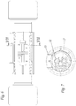
Figs. 6 and 7 show, respectively in a front plan view and in a section according to the plane VII-VII ofFig. 6 , the motorized axle with variable track in a generic configuration. - With reference to the details of the figures, a motorized axle with variable track for pick and carry crane, comprises:
- a
main support body 1; - a first 2 and a second 2' movable axle shaft;
- a first 3 and a second 3' cylinder of hydraulic or electric type;
- a first 4 and a second 4' hydraulic or electric motor;
- a first 5 and a second 5' gearmotor;
- a first 6 and a second 6' wheel connected to the
respective gearmotor 5, 5'; - at least a first and a second
anti-rotation feather key 9, 9'. - The
main body 1 is anchored to the machine to be driven through theblocks 10, 10'. In themain body 1 there are housed, with a coupling with one degree of freedom, that is, only sliding, a first 2 and a second 2' movable axle shaft. - Each
movable axle shaft 2, 2' is a structure comprising atube 11, 11' and two plates; at one side thetube 11, 11' is anchored to therespective motor 4, 4' andgearmotor 5, 5' through aplate 7, 7', while the opposite side is anchored to thecylinder rod 3, 3' through aferrule 8, 8'. - The body of each
cylinder 3, 3' is in turn anchored to themain support body 1 by means of screws, whosefixing holes 12, 12' are illustrated in the section ofFig. 7 . - The reciprocating movement of the
cylinder rods 3, 3' through the actuation of a selector, which can be a lever or a button, changes the dimensional configuration of the axle, as shown inFigs. 1A and 1B , changing the height X indicated inFigs. 3 and5 , allowing the track of the axle to be adjusted, improving the stability of the machine on which it is installed. - Rotation of the
movable axle shaft 2, 2' relative to themain body 1 is prevented through saidfeather keys 9, 9'.
Claims (2)
- A motorized axle with variable track for pick and carry crane of the type comprising a mobile machine and a crane, characterized in that said axle comprises:- a fixed main support body (1);- a first (2) and a second (2 ') movable axle shaft;- a first (3) and a second (3 ') cylinder of hydraulic or electric type comprising a body and a rod;- a first (4) and a second (4 ') motor of hydraulic or electric type;- a first (5) and a second (5 ') gearmotor;- a first (6) and a second (6 ') wheel connected to the respective gearmotor (5, 5');- at least a first (9) and a second (9 ') anti-rotation feather key, wherein said main body (1) is permanently anchored to the machine to be driven and in the interior thereof there are housed, with a coupling with one degree of freedom, that is, only sliding, said first (2) and second (2') movable axle shaft, wherein the rotation between said fixed main body (1) and each movable axle shaft (2, 2 ') is prevented by said at least a first (9) and a second (9') feather key; wherein each movable axle shaft (2, 2 ') comprises a tube (11, 11') and two plates (7, 7 ', 8, 8') and said tube (11, 11') at one side is anchored to the respective motor (4, 4') and gearmotor (5, 5') through said plate (7, 7 '), while the opposite side is anchored to the cylinder rod (3, 3') through said plate (8, 8') comprising a ferrule; wherein the variation in length of said cylinders (3, 3'), commanded by the actuation of a lever or button type selector, causes the sliding of said first and second movable axle shaft (2, 2') inside of said fixed main support body (1), determining the dimensional change of the axle.
- The motorized axle with variable track according to claim 1, characterized in that the body of said first and second cylinders (3, 3') is anchored to said fixed main support body (1) by means of screws.
Applications Claiming Priority (1)
| Application Number | Priority Date | Filing Date | Title |
|---|---|---|---|
| IT102016000098227A IT201600098227A1 (en) | 2016-09-30 | 2016-09-30 | MOTORIZED AXLE WITH VARIABLE TRACKING FOR CRANE PICK AND CARRY |
Publications (1)
| Publication Number | Publication Date |
|---|---|
| EP3301063A1 true EP3301063A1 (en) | 2018-04-04 |
Family
ID=58779256
Family Applications (1)
| Application Number | Title | Priority Date | Filing Date |
|---|---|---|---|
| EP17194262.6A Withdrawn EP3301063A1 (en) | 2016-09-30 | 2017-09-29 | A motorized axle with variable track for pick and carry crane |
Country Status (2)
| Country | Link |
|---|---|
| EP (1) | EP3301063A1 (en) |
| IT (1) | IT201600098227A1 (en) |
Citations (5)
| Publication number | Priority date | Publication date | Assignee | Title |
|---|---|---|---|---|
| DE570007C (en) * | 1933-02-10 | Andre Gesnel | Wheel axles adjustable in length for motor vehicles | |
| DE19710172A1 (en) * | 1997-03-12 | 1998-09-17 | Same Deutz Fahr Spa | Combine harvester with central gearing powering shafted end gears |
| EP1006075A1 (en) * | 1998-12-04 | 2000-06-07 | Up-Right, Inc. | Self-propelled boom vehicle |
| EP1325861A1 (en) * | 2002-01-04 | 2003-07-09 | BAUER Maschinen GmbH | Tracklaying undercarriage |
| US20150210115A1 (en) * | 2012-07-19 | 2015-07-30 | Haulotte Group | Axle and vehicle comprising at least one such axle |
-
2016
- 2016-09-30 IT IT102016000098227A patent/IT201600098227A1/en unknown
-
2017
- 2017-09-29 EP EP17194262.6A patent/EP3301063A1/en not_active Withdrawn
Patent Citations (5)
| Publication number | Priority date | Publication date | Assignee | Title |
|---|---|---|---|---|
| DE570007C (en) * | 1933-02-10 | Andre Gesnel | Wheel axles adjustable in length for motor vehicles | |
| DE19710172A1 (en) * | 1997-03-12 | 1998-09-17 | Same Deutz Fahr Spa | Combine harvester with central gearing powering shafted end gears |
| EP1006075A1 (en) * | 1998-12-04 | 2000-06-07 | Up-Right, Inc. | Self-propelled boom vehicle |
| EP1325861A1 (en) * | 2002-01-04 | 2003-07-09 | BAUER Maschinen GmbH | Tracklaying undercarriage |
| US20150210115A1 (en) * | 2012-07-19 | 2015-07-30 | Haulotte Group | Axle and vehicle comprising at least one such axle |
Also Published As
| Publication number | Publication date |
|---|---|
| IT201600098227A1 (en) | 2018-03-30 |
Similar Documents
| Publication | Publication Date | Title |
|---|---|---|
| US3868022A (en) | Self-propelled heavy duty mobile crane | |
| EP2497740B1 (en) | Movable rear counterweight device for crawler crane | |
| CN107572432B (en) | Self-balancing system of crawler crane | |
| EP3034453B2 (en) | An equipment with side-shifter | |
| JP5953315B2 (en) | Mobile telescopic crane | |
| EP3377395B1 (en) | Ballast for operating machine | |
| CN1307347C (en) | Oil pressure static pile press | |
| JP6766608B2 (en) | Backstop device for construction machinery | |
| CN101817480A (en) | Stop and bolt clamping unit | |
| CN110937556A (en) | Hydraulic System of Articulating Arm Aerial Work Vehicle | |
| EP3301063A1 (en) | A motorized axle with variable track for pick and carry crane | |
| CN104891396A (en) | Telescopic arm crawler type aerial work platform | |
| US20130328295A1 (en) | Stabilizer device for an operating machine | |
| ITMO20110048A1 (en) | SELF-PROPELLED OPERATING MACHINE WITH VARIABLE DRAWN AXLE | |
| CN109649483B (en) | Electro-hydraulic steering system for vehicle | |
| CN204185147U (en) | Three-dimensional adjustable hoisting crane | |
| EP3625164B1 (en) | Ballast for operating machinery | |
| JP6932471B2 (en) | How to use pile driver and pile driver | |
| RU2434803C1 (en) | Device for telescoping truck crane 4-section boom | |
| CN210127387U (en) | Automatic control system for swinging of right rear supporting leg of milling machine and milling machine thereof | |
| CN215716931U (en) | Indoor decoration frame for building | |
| CN219213681U (en) | Diamond wire saw convenient to sideslip | |
| GB1560666A (en) | Mobile lifting platforms | |
| CN109630486A (en) | A kind of pumping machine falls Automatic-clamping structure after arm | |
| US20170190550A1 (en) | Improved crane for lifting and transporting loads |
Legal Events
| Date | Code | Title | Description |
|---|---|---|---|
| PUAI | Public reference made under article 153(3) epc to a published international application that has entered the european phase |
Free format text: ORIGINAL CODE: 0009012 |
|
| AK | Designated contracting states |
Kind code of ref document: A1 Designated state(s): AL AT BE BG CH CY CZ DE DK EE ES FI FR GB GR HR HU IE IS IT LI LT LU LV MC MK MT NL NO PL PT RO RS SE SI SK SM TR |
|
| AX | Request for extension of the european patent |
Extension state: BA ME |
|
| STAA | Information on the status of an ep patent application or granted ep patent |
Free format text: STATUS: THE APPLICATION IS DEEMED TO BE WITHDRAWN |
|
| 18D | Application deemed to be withdrawn |
Effective date: 20181005 |