EP3301049A1 - Sheet conveying apparatus and image forming apparatus with unit for reversing the direction of the sheet - Google Patents
Sheet conveying apparatus and image forming apparatus with unit for reversing the direction of the sheet Download PDFInfo
- Publication number
- EP3301049A1 EP3301049A1 EP17190958.3A EP17190958A EP3301049A1 EP 3301049 A1 EP3301049 A1 EP 3301049A1 EP 17190958 A EP17190958 A EP 17190958A EP 3301049 A1 EP3301049 A1 EP 3301049A1
- Authority
- EP
- European Patent Office
- Prior art keywords
- sheet
- roller
- state
- reversing
- nip portion
- Prior art date
- Legal status (The legal status is an assumption and is not a legal conclusion. Google has not performed a legal analysis and makes no representation as to the accuracy of the status listed.)
- Granted
Links
Images









Classifications
-
- G—PHYSICS
- G03—PHOTOGRAPHY; CINEMATOGRAPHY; ANALOGOUS TECHNIQUES USING WAVES OTHER THAN OPTICAL WAVES; ELECTROGRAPHY; HOLOGRAPHY
- G03G—ELECTROGRAPHY; ELECTROPHOTOGRAPHY; MAGNETOGRAPHY
- G03G21/00—Arrangements not provided for by groups G03G13/00 - G03G19/00, e.g. cleaning, elimination of residual charge
- G03G21/16—Mechanical means for facilitating the maintenance of the apparatus, e.g. modular arrangements
- G03G21/1661—Mechanical means for facilitating the maintenance of the apparatus, e.g. modular arrangements means for handling parts of the apparatus in the apparatus
- G03G21/1695—Mechanical means for facilitating the maintenance of the apparatus, e.g. modular arrangements means for handling parts of the apparatus in the apparatus for paper transport
-
- B—PERFORMING OPERATIONS; TRANSPORTING
- B65—CONVEYING; PACKING; STORING; HANDLING THIN OR FILAMENTARY MATERIAL
- B65H—HANDLING THIN OR FILAMENTARY MATERIAL, e.g. SHEETS, WEBS, CABLES
- B65H85/00—Recirculating articles, i.e. feeding each article to, and delivering it from, the same machine work-station more than once
-
- B—PERFORMING OPERATIONS; TRANSPORTING
- B41—PRINTING; LINING MACHINES; TYPEWRITERS; STAMPS
- B41F—PRINTING MACHINES OR PRESSES
- B41F21/00—Devices for conveying sheets through printing apparatus or machines
- B41F21/10—Combinations of transfer drums and grippers
- B41F21/106—Combinations of transfer drums and grippers for reversing sheets, e.g. for perfecting machine
-
- B—PERFORMING OPERATIONS; TRANSPORTING
- B41—PRINTING; LINING MACHINES; TYPEWRITERS; STAMPS
- B41J—TYPEWRITERS; SELECTIVE PRINTING MECHANISMS, i.e. MECHANISMS PRINTING OTHERWISE THAN FROM A FORME; CORRECTION OF TYPOGRAPHICAL ERRORS
- B41J13/00—Devices or arrangements of selective printing mechanisms, e.g. ink-jet printers or thermal printers, specially adapted for supporting or handling copy material in short lengths, e.g. sheets
- B41J13/02—Rollers
-
- B—PERFORMING OPERATIONS; TRANSPORTING
- B65—CONVEYING; PACKING; STORING; HANDLING THIN OR FILAMENTARY MATERIAL
- B65H—HANDLING THIN OR FILAMENTARY MATERIAL, e.g. SHEETS, WEBS, CABLES
- B65H29/00—Delivering or advancing articles from machines; Advancing articles to or into piles
- B65H29/12—Delivering or advancing articles from machines; Advancing articles to or into piles by means of the nip between two, or between two sets of, moving tapes or bands or rollers
- B65H29/125—Delivering or advancing articles from machines; Advancing articles to or into piles by means of the nip between two, or between two sets of, moving tapes or bands or rollers between two sets of rollers
-
- B—PERFORMING OPERATIONS; TRANSPORTING
- B65—CONVEYING; PACKING; STORING; HANDLING THIN OR FILAMENTARY MATERIAL
- B65H—HANDLING THIN OR FILAMENTARY MATERIAL, e.g. SHEETS, WEBS, CABLES
- B65H5/00—Feeding articles separated from piles; Feeding articles to machines
- B65H5/06—Feeding articles separated from piles; Feeding articles to machines by rollers or balls, e.g. between rollers
- B65H5/062—Feeding articles separated from piles; Feeding articles to machines by rollers or balls, e.g. between rollers between rollers or balls
-
- B—PERFORMING OPERATIONS; TRANSPORTING
- B65—CONVEYING; PACKING; STORING; HANDLING THIN OR FILAMENTARY MATERIAL
- B65H—HANDLING THIN OR FILAMENTARY MATERIAL, e.g. SHEETS, WEBS, CABLES
- B65H7/00—Controlling article feeding, separating, pile-advancing, or associated apparatus, to take account of incorrect feeding, absence of articles, or presence of faulty articles
- B65H7/02—Controlling article feeding, separating, pile-advancing, or associated apparatus, to take account of incorrect feeding, absence of articles, or presence of faulty articles by feelers or detectors
- B65H7/14—Controlling article feeding, separating, pile-advancing, or associated apparatus, to take account of incorrect feeding, absence of articles, or presence of faulty articles by feelers or detectors by photoelectric feelers or detectors
-
- G—PHYSICS
- G03—PHOTOGRAPHY; CINEMATOGRAPHY; ANALOGOUS TECHNIQUES USING WAVES OTHER THAN OPTICAL WAVES; ELECTROGRAPHY; HOLOGRAPHY
- G03G—ELECTROGRAPHY; ELECTROPHOTOGRAPHY; MAGNETOGRAPHY
- G03G15/00—Apparatus for electrographic processes using a charge pattern
- G03G15/22—Apparatus for electrographic processes using a charge pattern involving the combination of more than one step according to groups G03G13/02 - G03G13/20
- G03G15/23—Apparatus for electrographic processes using a charge pattern involving the combination of more than one step according to groups G03G13/02 - G03G13/20 specially adapted for copying both sides of an original or for copying on both sides of a recording or image-receiving material
- G03G15/231—Arrangements for copying on both sides of a recording or image-receiving material
-
- G—PHYSICS
- G03—PHOTOGRAPHY; CINEMATOGRAPHY; ANALOGOUS TECHNIQUES USING WAVES OTHER THAN OPTICAL WAVES; ELECTROGRAPHY; HOLOGRAPHY
- G03G—ELECTROGRAPHY; ELECTROPHOTOGRAPHY; MAGNETOGRAPHY
- G03G15/00—Apparatus for electrographic processes using a charge pattern
- G03G15/22—Apparatus for electrographic processes using a charge pattern involving the combination of more than one step according to groups G03G13/02 - G03G13/20
- G03G15/23—Apparatus for electrographic processes using a charge pattern involving the combination of more than one step according to groups G03G13/02 - G03G13/20 specially adapted for copying both sides of an original or for copying on both sides of a recording or image-receiving material
- G03G15/231—Arrangements for copying on both sides of a recording or image-receiving material
- G03G15/232—Arrangements for copying on both sides of a recording or image-receiving material using a single reusable electrographic recording member
- G03G15/234—Arrangements for copying on both sides of a recording or image-receiving material using a single reusable electrographic recording member by inverting and refeeding the image receiving material with an image on one face to the recording member to transfer a second image on its second face, e.g. by using a duplex tray; Details of duplex trays or inverters
-
- G—PHYSICS
- G03—PHOTOGRAPHY; CINEMATOGRAPHY; ANALOGOUS TECHNIQUES USING WAVES OTHER THAN OPTICAL WAVES; ELECTROGRAPHY; HOLOGRAPHY
- G03G—ELECTROGRAPHY; ELECTROPHOTOGRAPHY; MAGNETOGRAPHY
- G03G15/00—Apparatus for electrographic processes using a charge pattern
- G03G15/65—Apparatus which relate to the handling of copy material
- G03G15/6552—Means for discharging uncollated sheet copy material, e.g. discharging rollers, exit trays
-
- G—PHYSICS
- G03—PHOTOGRAPHY; CINEMATOGRAPHY; ANALOGOUS TECHNIQUES USING WAVES OTHER THAN OPTICAL WAVES; ELECTROGRAPHY; HOLOGRAPHY
- G03G—ELECTROGRAPHY; ELECTROPHOTOGRAPHY; MAGNETOGRAPHY
- G03G15/00—Apparatus for electrographic processes using a charge pattern
- G03G15/65—Apparatus which relate to the handling of copy material
- G03G15/6555—Handling of sheet copy material taking place in a specific part of the copy material feeding path
- G03G15/6579—Refeeding path for composite copying
-
- B—PERFORMING OPERATIONS; TRANSPORTING
- B41—PRINTING; LINING MACHINES; TYPEWRITERS; STAMPS
- B41J—TYPEWRITERS; SELECTIVE PRINTING MECHANISMS, i.e. MECHANISMS PRINTING OTHERWISE THAN FROM A FORME; CORRECTION OF TYPOGRAPHICAL ERRORS
- B41J11/00—Devices or arrangements of selective printing mechanisms, e.g. ink-jet printers or thermal printers, for supporting or handling copy material in sheet or web form
- B41J11/02—Platens
- B41J11/04—Roller platens
-
- B—PERFORMING OPERATIONS; TRANSPORTING
- B65—CONVEYING; PACKING; STORING; HANDLING THIN OR FILAMENTARY MATERIAL
- B65H—HANDLING THIN OR FILAMENTARY MATERIAL, e.g. SHEETS, WEBS, CABLES
- B65H2301/00—Handling processes for sheets or webs
- B65H2301/30—Orientation, displacement, position of the handled material
- B65H2301/33—Modifying, selecting, changing orientation
- B65H2301/333—Inverting
-
- B—PERFORMING OPERATIONS; TRANSPORTING
- B65—CONVEYING; PACKING; STORING; HANDLING THIN OR FILAMENTARY MATERIAL
- B65H—HANDLING THIN OR FILAMENTARY MATERIAL, e.g. SHEETS, WEBS, CABLES
- B65H2301/00—Handling processes for sheets or webs
- B65H2301/40—Type of handling process
- B65H2301/44—Moving, forwarding, guiding material
- B65H2301/443—Moving, forwarding, guiding material by acting on surface of handled material
- B65H2301/4431—Moving, forwarding, guiding material by acting on surface of handled material by means with operating surfaces contacting opposite faces of material
- B65H2301/44318—Moving, forwarding, guiding material by acting on surface of handled material by means with operating surfaces contacting opposite faces of material between rollers
-
- B—PERFORMING OPERATIONS; TRANSPORTING
- B65—CONVEYING; PACKING; STORING; HANDLING THIN OR FILAMENTARY MATERIAL
- B65H—HANDLING THIN OR FILAMENTARY MATERIAL, e.g. SHEETS, WEBS, CABLES
- B65H2404/00—Parts for transporting or guiding the handled material
- B65H2404/10—Rollers
- B65H2404/14—Roller pairs
- B65H2404/142—Roller pairs arranged on movable frame
-
- B—PERFORMING OPERATIONS; TRANSPORTING
- B65—CONVEYING; PACKING; STORING; HANDLING THIN OR FILAMENTARY MATERIAL
- B65H—HANDLING THIN OR FILAMENTARY MATERIAL, e.g. SHEETS, WEBS, CABLES
- B65H2404/00—Parts for transporting or guiding the handled material
- B65H2404/10—Rollers
- B65H2404/14—Roller pairs
- B65H2404/142—Roller pairs arranged on movable frame
- B65H2404/1421—Roller pairs arranged on movable frame rotating, pivoting or oscillating around an axis, e.g. parallel to the roller axis
-
- B—PERFORMING OPERATIONS; TRANSPORTING
- B65—CONVEYING; PACKING; STORING; HANDLING THIN OR FILAMENTARY MATERIAL
- B65H—HANDLING THIN OR FILAMENTARY MATERIAL, e.g. SHEETS, WEBS, CABLES
- B65H2404/00—Parts for transporting or guiding the handled material
- B65H2404/10—Rollers
- B65H2404/14—Roller pairs
- B65H2404/144—Roller pairs with relative movement of the rollers to / from each other
-
- B—PERFORMING OPERATIONS; TRANSPORTING
- B65—CONVEYING; PACKING; STORING; HANDLING THIN OR FILAMENTARY MATERIAL
- B65H—HANDLING THIN OR FILAMENTARY MATERIAL, e.g. SHEETS, WEBS, CABLES
- B65H2404/00—Parts for transporting or guiding the handled material
- B65H2404/10—Rollers
- B65H2404/15—Roller assembly, particular roller arrangement
-
- B—PERFORMING OPERATIONS; TRANSPORTING
- B65—CONVEYING; PACKING; STORING; HANDLING THIN OR FILAMENTARY MATERIAL
- B65H—HANDLING THIN OR FILAMENTARY MATERIAL, e.g. SHEETS, WEBS, CABLES
- B65H2404/00—Parts for transporting or guiding the handled material
- B65H2404/10—Rollers
- B65H2404/15—Roller assembly, particular roller arrangement
- B65H2404/152—Arrangement of roller on a movable frame
-
- B—PERFORMING OPERATIONS; TRANSPORTING
- B65—CONVEYING; PACKING; STORING; HANDLING THIN OR FILAMENTARY MATERIAL
- B65H—HANDLING THIN OR FILAMENTARY MATERIAL, e.g. SHEETS, WEBS, CABLES
- B65H2404/00—Parts for transporting or guiding the handled material
- B65H2404/20—Belts
- B65H2404/26—Particular arrangement of belt, or belts
- B65H2404/269—Particular arrangement of belt, or belts other arrangements
- B65H2404/2693—Arrangement of belts on movable frame
-
- B—PERFORMING OPERATIONS; TRANSPORTING
- B65—CONVEYING; PACKING; STORING; HANDLING THIN OR FILAMENTARY MATERIAL
- B65H—HANDLING THIN OR FILAMENTARY MATERIAL, e.g. SHEETS, WEBS, CABLES
- B65H2555/00—Actuating means
- B65H2555/20—Actuating means angular
-
- B—PERFORMING OPERATIONS; TRANSPORTING
- B65—CONVEYING; PACKING; STORING; HANDLING THIN OR FILAMENTARY MATERIAL
- B65H—HANDLING THIN OR FILAMENTARY MATERIAL, e.g. SHEETS, WEBS, CABLES
- B65H2801/00—Application field
- B65H2801/03—Image reproduction devices
-
- B—PERFORMING OPERATIONS; TRANSPORTING
- B65—CONVEYING; PACKING; STORING; HANDLING THIN OR FILAMENTARY MATERIAL
- B65H—HANDLING THIN OR FILAMENTARY MATERIAL, e.g. SHEETS, WEBS, CABLES
- B65H2801/00—Application field
- B65H2801/03—Image reproduction devices
- B65H2801/06—Office-type machines, e.g. photocopiers
-
- B—PERFORMING OPERATIONS; TRANSPORTING
- B65—CONVEYING; PACKING; STORING; HANDLING THIN OR FILAMENTARY MATERIAL
- B65H—HANDLING THIN OR FILAMENTARY MATERIAL, e.g. SHEETS, WEBS, CABLES
- B65H2801/00—Application field
- B65H2801/03—Image reproduction devices
- B65H2801/12—Single-function printing machines, typically table-top machines
-
- B—PERFORMING OPERATIONS; TRANSPORTING
- B65—CONVEYING; PACKING; STORING; HANDLING THIN OR FILAMENTARY MATERIAL
- B65H—HANDLING THIN OR FILAMENTARY MATERIAL, e.g. SHEETS, WEBS, CABLES
- B65H3/00—Separating articles from piles
- B65H3/02—Separating articles from piles using friction forces between articles and separator
- B65H3/06—Rollers or like rotary separators
- B65H3/0638—Construction of the rollers or like rotary separators
-
- G—PHYSICS
- G03—PHOTOGRAPHY; CINEMATOGRAPHY; ANALOGOUS TECHNIQUES USING WAVES OTHER THAN OPTICAL WAVES; ELECTROGRAPHY; HOLOGRAPHY
- G03G—ELECTROGRAPHY; ELECTROPHOTOGRAPHY; MAGNETOGRAPHY
- G03G2215/00—Apparatus for electrophotographic processes
- G03G2215/00362—Apparatus for electrophotographic processes relating to the copy medium handling
- G03G2215/00535—Stable handling of copy medium
- G03G2215/00556—Control of copy medium feeding
Definitions
- the present invention relates to a sheet conveying apparatus for continuously conveying sheets, and an image forming apparatus, such as a copying apparatus, a printer, and a facsimile, having the sheet conveying apparatus.
- Japanese Patent Application Laid-Open No. 2015-083353 discusses a configuration in which a reversing unit for performing sheet reversing includes a reversing roller group including a drive roller rotating in one direction while receiving a driving force, a first driven roller, and a second driven roller.
- the three different rollers (the first driven roller, the drive roller, and the second driven roller) are disposed in approximately one straight line in this order in the direction intersecting with the sheet conveyance direction.
- the first driven roller faces the drive roller to form a first nip portion.
- the second driven roller faces the drive roller from a direction different from the direction of the first driven roller to form a second nip portion.
- the reversing unit discussed in Japanese Patent Application Laid-Open No. 2015-083353 performs the following sheet reversing.
- a sheet with an image formed on the first surface is conveyed toward the first nip portion of the reversing roller group.
- the sheet is conveyed in the first direction as the direction of sheet discharge from the reversing roller group at the first nip portion, and the trailing edge of the sheet in the sheet conveyance direction passes through the first nip portion.
- the reversing unit includes a switchback unit for temporarily storing the sheet on the downstream side of the first nip portion in the sheet conveyance direction. The sheet that has passed through the first nip portion is stored in the switchback unit.
- the trailing edge of the sheet is led to the second nip portion of the reversing roller group. Since the drive roller is rotating in one direction, the sheet nipped by the second nip portion is conveyed in the second direction opposite to the first direction as the sheet conveyance direction at the first nip portion. Then, the sheet is re-conveyed to the image forming unit. After an image is formed on the second surface of the sheet, the sheet is conveyed to the discharge unit provided at a position different from the position of the reversing unit. Then, the sheet is discharged out of the image forming apparatus by the discharge roller of the discharge unit.
- the present invention is directed to a sheet conveying apparatus capable of switching the nip portion for nipping a sheet before the trailing edge of the sheet in the sheet conveyance direction has been completely discharged from a first nip portion.
- a sheet conveying apparatus capable of switching the nip portion for nipping a sheet before the trailing edge of the sheet in the sheet conveyance direction has been completely discharged from a first nip portion.
- a sheet conveying apparatus as specified in claims 1 to 14.
- an image forming apparatus as specified in claim 15.
- Fig. 1 is a sectional view schematically illustrating a configuration of an image forming apparatus 1 having the sheet conveying apparatus of the present invention.
- the image forming apparatus 1 includes a main body 2 of the image forming apparatus 1, a feed unit 3, an image forming unit 4, a conveyance unit 5, a reversing unit 6, and a control unit 7.
- the main body 2 includes the feed unit 3, the image forming unit 4, the conveyance unit 5, the reversing unit 6, and the control unit 7.
- a sheet supplying cassette 21 as an accommodation unit is detachably attached on the upstream side of the feed unit 3 in the sheet conveyance direction.
- the sheet supplying cassette 21 feeds unprinted sheets S stored therein in a stacked state.
- the sheet S is discharged onto a discharge tray 22 serving as a stacking unit for stacking sheets discharged from the main body 2.
- the discharge tray 22 is formed on the downstream side of the reversing unit 6 in the sheet conveyance direction.
- the feed unit 3 includes a feed roller 30 and a separation portion 31 formed of a separation pad 31a and a separation holder 31b for holding the separation pad 31a.
- the separation pad 31a is in pressure contact with the feed roller 30.
- the sheets S stored in the sheet supplying cassette 21 are fed to the separation portion 31 by the rotation of the feed roller 30. After the sheets S are separated one by one by the separation portion 31, a sheet S is fed to a first conveyance path 50.
- the image forming unit 4 includes a photosensitive drum 40 as an image bearing member, a laser scanner unit 41, a development unit 42, a transfer roller 43, and a fixing unit 44.
- the laser scanner unit 41 irradiates the photosensitive drum 40 uniformly charged by a charging unit (not illustrated) based on image information. Then, an electrostatic latent image is formed on the surface of the photosensitive drum 40.
- the development unit 42 develops the electrostatic latent image to form a toner image on the surface of the photosensitive drum 40.
- the transfer roller 43 transfers the developed toner image onto the sheet S.
- the fixing unit 44 heats and pressurizes the sheet S to fix the toner image onto the sheet S. In this way, an image is formed on the sheet S in the image forming unit 4.
- Fig. 2 is a sectional view schematically illustrating a configuration of the reversing unit 6 according to the present exemplary embodiment.
- the configuration of the reversing unit 6 will be described below with reference to Fig. 2 .
- the reversing unit 6 includes a drive roller 62 (first rotary member) rotating in one direction (in the direction of the arrow R1) while receiving a driving force from a driving source, a discharge roller 61 (second rotary member) driven by the rotation of the drive roller 62, and a reversing roller 63 (third rotary member).
- the discharge roller 61 contacts the drive roller 62 to form a first nip portion N1 at which the discharge roller 61 nips and conveys the sheet S together with the drive roller 62.
- the reversing roller 63 contacts the drive roller 62 at a position different from the position of the discharge roller 61 in the circumferential direction of the drive roller 62 to form a second nip portion N2 at which the reversing roller 63 nips and conveys the sheet S together with the drive roller 62.
- the drive roller 62 and the discharge roller 61 convey the sheet S from the drive roller 62 to the discharge tray 22 and then discharge the sheet S from the first nip portion N1.
- the direction in which the sheet S is discharged from the first nip portion N1 to the discharge tray 22 is referred to as a discharge direction (first direction) .
- the drive roller 62 is rotating in one direction while receiving a driving force. Therefore, at the second nip portion N2, the sheet S is conveyed from the discharge tray 22 to the second conveyance path 51 in the second direction different from the sheet conveyance direction at the first nip portion N1.
- the direction in which the sheet S having been conveyed in the discharge direction toward the discharge tray 22 is conveyed from the discharge tray 22 to the reversing unit 6 is referred to as a reversing direction (second direction).
- the sheet S is conveyed in the first direction at the first nip portion N1 and conveyed in the second direction opposite to the first direction at the second nip portion N2.
- the reversing unit 6 moves the discharge roller 61, the sheet S nip state is switched from the state of being nipped by the first nip portion N1 to the state of being nipped by the second nip portion N2.
- a moving operation of the discharge roller 61 for switching the sheet S nip state will be described in detail below.
- the conveyance unit 5 includes a first conveyance path 50, a second conveyance path 51, a conveyance roller pair 52, a re-conveyance roller pair 53, a first sensor 54, and a second sensor 55.
- the first conveyance path 50 is used to convey the sheet S to the image forming unit 4 to reform an image on the sheet S conveyed from the sheet supplying cassette 21 and the sheet S conveyed in the reversing direction by the reversing unit 6.
- the downstream side of the first conveyance path 50 is connected to the first nip portion N1 of the reversing unit 6, and the upstream side of the first conveyance path 50 is divided into two paths in the sheet S conveyance direction.
- One of the two division paths of the first conveyance path 50 is connected to the sheet supplying cassette 21.
- the sheet S is fed from the sheet supplying cassette 21 to the first conveyance path 50.
- a toner image is transferred onto the sheet S by the transfer roller 43.
- the other of the two division paths of the first conveyance path 50 is connected to the second conveyance path 51 for re-conveying to the first conveyance path 50 the sheet S conveyed in the reversing direction by the reversing unit 6.
- the upstream side of the second conveyance path 51 is connected to the second nip portion N2 of the reversing unit 6, and the downstream side of the second conveyance path 51 is connected to the other of the two division paths of the first conveyance path 50 in the sheet conveyance direction.
- the conveyance roller pair 52 disposed in the first conveyance path 50 conveys along the first conveyance path 50 the sheet S fed or conveyed in the first conveyance path 50.
- the re-conveyance roller pair 53 disposed in the second conveyance path 51 conveys to the first conveyance path 50 the sheet S conveyed in the second conveyance path 51.
- the first sensor 54 disposed between the feed unit 3 and the image forming unit 4 in the first conveyance path 50 detects the positions of the leading and trailing edges of the sheet S passing through the first sensor 54.
- the second sensor 55 disposed on the downstream side of the first conveyance path 50 in the sheet conveyance direction detects the positions of the leading and trailing edges of the sheet S passing through the second sensor 55, similar to the first sensor 54.
- Each of the first sensor 54 and the second sensor 55 includes a sensor flag (not illustrated) biased in the direction of contact with the sheet S and rotated by the passage of the sheet S, and a photo-interrupter (not illustrated) as an optical sensor. In such a configuration, when the sheet S passes through each sensor, the sensor flag is pushed down and rotated to block or open the detection area of the photo-interrupter, making it possible to detect the leading and trailing edges of the sheet S.
- the first sensor 54 and the second sensor 55 include a sensor flag which is rotated by the passage of the sheet S
- a sensor for detecting the leading and trailing edges of the sheet S is not limited thereto.
- the first sensor 54 and the second sensor 55 may be an optical sensor for detecting the presence or absence of the sheet S.
- a light emitting element irradiates the sheet S with light and a light receiving element receives penetrated or reflected light.
- the control unit 7 controls the drive related to the sheet S conveyance, such as the feed roller 30, the conveyance roller pair 52, the re-conveyance roller pair 53, and the reversing unit 6, and controls moving operations of the discharge roller 61 in the reversing unit 6. Control of operations of the reversing unit 6 by the control unit 7 will be described in detail below.
- FIG. 3 is a schematic view illustrating a configuration of the reversing unit 6 according to the present exemplary embodiment when viewed from the downstream side in the sheet conveyance direction.
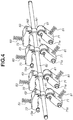
- Fig. 4 is a schematic view illustrating a configurations of the discharge rollers 61, the drive roller 62, and the reversing rollers 63 according to the present exemplary embodiment.
- Fig. 5 is a block diagram illustrating drive control according to the present exemplary embodiment.
- both ends of the drive roller 62 are rotatably held by drive roller holders 65 which are rotatable centering on fulcrums 66.
- the drive roller holder 65 holds the drive roller 62 on one side of the fulcrum 66 and is provided with a guide groove 65a on the other side.
- a cam shaft 68 is disposed to face the drive roller 62 in approximately parallel with the drive roller 62. Both ends of the cam shaft 68 are provided with cams 67 which are integrally rotatable with the cam shaft 68.
- a cam 67 has a cylindrical protruding portion 67a on a surface different from the surface holding the cam shaft 68. When the protruding portion 67a engages with the guide groove 65a, the cam 67 is held by the drive roller holder 65.
- One end of the cam shaft 68 is provided with a cam drive unit 69 (formed of a solenoid 69a as a changeover member, and a partially-toothless gear 69b) that can turn the drive for rotating the cam 67 ON and OFF.
- the reversing guide 64 are supported by both ends of the drive roller 62 in the axial direction.
- One end portion 64a of the reversing guide 64 on the side of the drive roller 62 is rotatably held by a bearing portion 65b of the drive roller holder 65.
- the other end of the reversing guide 64 is provided with a cylindrical protruding portion 64b. When the protruding portion 64b engages with a groove portion 72 provided in the main body 2, the orientation of the reversing guide 64 is maintained.
- each discharge roller 61 contacts the drive roller 62 to form a first nip portion N1, and is held by a discharge roller holder 71 movable centering on a fulcrum 71a.
- the discharge roller holder 71 is biased toward the drive roller 62 by a spring 81 (first biasing member) provided in the main body 2.
- the drive roller 62 being pressed by the discharge roller 61 forms the first nip portion N1.
- Each reversing roller 63 contacts the drive roller 62 to form a second nip portion N2, and is held by a reversing roller holder 73 movable centering on a fulcrum 73a.
- the reversing roller holder 73 is biased toward the drive roller 62 by a spring 83 (second biasing member) provided in the main body 2.
- the drive roller 62 being pressed by the reversing roller 63 forms the second nip portion N2.
- FIG. 5 A block diagram illustrating drive control according to the present exemplary embodiment will be described below with reference to Fig. 5 .
- the drive roller 62 with one end connected to a gear 70 rotates while receiving a driving force from a drive motor 90 as a driving source via the gear 70.
- the drive motor 90 rotates in one direction, and the drive roller 62 also rotates in one direction.
- the CPU 110 is connected with the drive motor 90, the solenoid 69a, the feed roller 30, the first sensor 54, and the second sensor 55.
- the CPU 110 is connected with a read only memory (ROM) and a random access memory (RAM), and executes a program stored in the ROM by using the RAM as a work memory.
- ROM read only memory
- RAM random access memory
- the CPU 110, the ROM, and the RAM constitute the control unit 7.
- the control unit 7 controls the drive motor 90 and the solenoid 69a, the drive roller 62 rotates and the cam drive unit 69 moves the drive roller 62 in the reversing unit 6.
- Fig. 6A is a schematic view when the reversing unit 6 before the moving operation of the drive roller 62 is performed is viewed from the axial direction of the drive roller 62.
- the position of the drive roller 62 at this timing is the initial position (first position). At the initial position, the drive roller 62 is rotating in one direction while receiving a driving force from the driving source.
- the drive roller 62 held on both ends by the drive roller holders 65 moves in the direction away from the discharge roller 61 and the reversing roller 63 (in the direction of the arrow B).
- the reversing guides 64 are supported by both ends of the drive roller 62.
- One end portion 64a of the reversing guide 64 is held by the drive roller holder 65. Therefore, the reversing guide 64 moves together with the drive roller 62. Since the protruding portion 64b of the reversing guide 64 engages with the groove portion 72, the reversing guide 64 moves along with the groove portion 72 while changing the angle with respect to the drive roller holder 65.
- the gear 70 connected with one end of the drive roller 62 also moves together with the drive roller 62. Even during movement, the drive roller 62 rotates in one direction while receiving a driving force from the drive motor 90 as a driving source.
- Fig. 6B is a schematic view illustrating the reversing unit 6 when the drive roller 62 and the reversing guide 64 move by the rotation of the cam 67 and the moving amount of the drive roller 62 is maximized, when viewed from the axial direction of the drive roller 62.
- the drive roller 62 is positioned at a retracted position (second position) where the drive roller 62 is retracted from the initial position.
- the discharge roller 61 held by the discharge roller holder 71 is biased toward the drive roller 62 by the spring 81 provided in the main body 2.
- the discharge roller holder 71 rotates centering on the fulcrum 71a, and the discharge roller 61 moves toward the reversing roller 63.
- the reversing roller 63 held by the reversing roller holder 73 is biased toward the drive roller 62 by the spring 83 provided in the main body 2.
- the reversing roller holder 73 rotates centering on the fulcrum 73a, and the reversing roller 63 moves toward the discharge roller 61.
- the rotational angle of the discharge roller holder 71 is regulated up to the position illustrated in Fig. 6B by a regulation member (not illustrated).
- the reversing roller 63 moves up to a position where it contacts the discharge roller 61 stopped at the position illustrated in Fig. 6B .
- the reversing roller 63 and the discharge roller 61 contact each other to form a third nip portion N3 which can nip and hold the conveyed sheet S.
- the cam 67 is locked at the position where the drive is canceled. More specifically, the above-described sequential moving operation of the drive roller 62 in the reversing unit 6 continuously takes place while the cam 67 makes one revolution by the cam drive unit 69. Since the drive roller 62 moves together with the gear 70, the drive roller 62 continues rotating in one direction while receiving a driving force from the drive motor 90 via the gear 70 during the above-described sequential moving operation of the drive roller 62 with respect to the discharge roller 61 and the reversing roller 63.
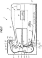
- Fig. 7 is a sectional view schematically illustrating a state after the sheet S stored in the sheet supplying cassette 21 is fed by the feed roller 30.
- the sheet S taken out from the sheet supplying cassette 21 by the feed roller 30 is separated by the separation portion 31, fed to the first conveyance path 50 and conveyed to the image forming unit 4 by the conveyance roller pair 52.
- the leading edge of the sheet S is detected by the first sensor 54, and an image is formed on the first surface of the sheet S in the image forming unit 4 at a timing based on detection information.
- Fig. 8 is a sectional view schematically illustrating a state after the sheet S with an image formed on the first surface has been conveyed to the reversing unit 6 and immediately before a moving operation of the drive roller 62 is started.
- the sheet S is nipped by the first nip portion N1 formed by the drive roller 62 and the discharge roller 61 and conveyed in the direction of the arrow drawn by a solid line (first direction).
- the sheet S is conveyed in the first direction in a state (first state) where the first surface contacts the discharge roller 61 and the second surface contacts the drive roller 62.
- the trailing edge of the sheet S in contact with the drive roller 62 and the discharge roller 61 at the first nip portion N1 is detected by the second sensor 55. Based on the detection information, the drive roller 62 starts moving before the trailing edge of the sheet S has been conveyed at the first nip portion N1. More specifically, according to the present exemplary embodiment, the discharge roller 61 starts moving before the trailing edge of the sheet S completely exits the first nip portion N1. When the sheet S nipped at the first nip portion N1 has been conveyed in the first direction, the sheet S is then nipped by the second nip portion N2 with the movement of the drive roller 62.
- the movement of the drive roller 62 is started when the control unit 7 controls the solenoid 69a based on the detection information from the second sensor 55.
- the control unit 7 may perform control to start the movement of the drive roller 62 based on information about the detection of the leading edge of the sheet S by the second sensor 55.
- a moving operation of the drive roller 62 when the sheet S nip state is switched from the state of being nipped by the first nip portion N1 to the state of being nipped by the second nip portion N2 will be described in detail below with reference to Figs. 11A to 11E .
- Fig. 9 is a sectional view schematically illustrating a state where the sheet S is nipped at the second nip portion N2 after the moving operation of the drive roller 62.
- the sheet S is conveyed in the direction of the arrow drawn by a solid line (second direction different from the first direction) at the second nip portion N2.
- the sheet S is conveyed in the second direction in a state (second state) where the second surface contacts the reversing roller 63 and the first surface contacts the drive roller 62.
- the sheet S having been conveyed in the first direction at the first nip portion N1 is conveyed in the second direction at the second nip portion N2 and then conveyed to the second conveyance path 51.
- Fig. 10 is a sectional view schematically illustrating a state after the sheet S has been conveyed in the second direction and immediately before the sheet S is re-conveyed to the image forming unit 4.
- the sheet S having been conveyed to the second conveyance path 51 is conveyed to the first conveyance path 50 by the re-conveyance roller pair 53.
- a toner image is transferred to the second surface of the sheet S by the transfer roller 43, and the toner image formed on the second surface is fixed by the fixing unit 44.
- toner images have been formed on both surfaces (the first and the second surfaces) of the sheet S.
- the sheet S with images formed on both surfaces is conveyed to the reversing unit 6, re-conveyed in the first direction at the first nip portion N1, and then discharged onto the discharge tray 22. At this timing, the drive roller 62 does not move. This completes two-sided printing on the sheet S according to the present exemplary embodiment.
- a switching unit including the drive roller holders 65, the cams 67, the cam shaft 68, and the cam drive unit 69 moves the drive roller 62 to switch the sheet S nip state from the first state to the second state.
- Fig. 11A is a schematic view illustrating a state after the sheet S with an image formed on the first surface is conveyed to the first nip portion N1 and immediately before a moving operation of the drive roller 62 is started.
- the drive roller 62 is rotating in one direction at the initial position (first position).
- the drive roller 62 starts moving in the direction away from the discharge roller 61 and the reversing roller 63.
- the trailing edge Re of the sheet S refers to the most trailing edge of the sheet S in the first sheet S conveyance direction.
- Fig. 11B is a schematic view illustrating a state where the drive roller 62 starts moving from the initial position (first position).
- the drive roller 62 contacts the discharge roller 61 to form a first nip portion N1.
- the reversing roller 63 biased by the spring 83 and the discharge roller 61 biased by the spring 81 contact each other via the sheet S to form a third nip portion N3.
- the sheet S is nipped by the first nip portion N1 and the third nip portion N3 and conveyed in the first direction in a state (third state) where the first surface contacts the discharge roller 61 and the second surface contacts the drive roller 62 and the reversing roller 63.
- the sheet S nip state is switched from the first state to the third state by the switching unit.
- the third state where the sheet S is nipped by two different positions (the first nip portion N1 and the third nip portion N3) is formed. Then, the sheet S is nipped by the third nip portion N3. This prevents the sheet S from dropping from the reversing unit 6 when switching the sheet S nip portion by moving the drive roller 62.
- Fig. 11C is a schematic view illustrating a sheet S state when the drive roller 62 has moved to the retracted position where the moving amount of the drive roller 62 is maximized.
- the drive roller 62 moves to the upstream side of the trailing edge Re of the sheet S in contact with the drive roller 62 and the discharge roller 61 at the first nip portion N1 in the sheet S conveyance direction at the first nip portion N1.
- the trailing edge Re of the sheet S nipped at the third nip portion N3 moves above the drive roller 62 having moved to the retracted position due to the self-weight and rigidity of the sheet S or the nipped position and angle of the sheet S at the third nip portion N3.
- the drive roller 62 moves from the lower surface side, i.e., the first surface of the sheet S nipped by the third nip portion N3 to approach the discharge roller 61 and the reversing roller 63, i.e., the drive roller 62 moves from the retracted position to the initial position.
- Fig. 11D is a schematic view illustrating a sheet S state while the drive roller 62 is moving from the retracted position to the initial position.
- the discharge roller 61 and the reversing roller 63 contact each other to form a third nip portion N3, and the sheet S is nipped by the third nip portion N3.
- the drive roller 62 moving to the initial position contacts the reversing roller 63 via the sheet S to form a second nip portion N2.
- the sheet S is nipped by the second nip portion N2 and the third nip portion N3 and conveyed in the second direction in a state (third state) where the first surface contacts the discharge roller 61 and the drive roller 62 and the second surface contacts the reversing roller 63. Subsequently, the drive roller 62 moves to the initial position so as to widen the space between the discharge roller 61 and the reversing roller 63.
- Fig. 11E is a schematic view illustrating a sheet S state when the drive roller 62 has moved to the initial position.
- the drive roller 62 moves from the lower surface side of the sheet S to the initial position. Therefore, upon completion of the moving operation of the drive roller 62, the sheet S is nipped by the second nip portion N2 formed when the drive roller 62 and the reversing roller 63 contact each other. More specifically, the sheet S is nipped at the second nip portion N2 and conveyed in the second direction in a state (second state) where the first surface contacts the drive roller 62 and the second surface contacts the reversing roller 63.
- the third state where the sheet S is nipped by two different positions (the second nip portion N2 and the third nip portion N3) is formed. Then, the sheet S is nipped by the second nip portion N2.
- the sheet S nip state is switched from the third state to the second state by the switching unit. This prevents the sheet S from dropping from the reversing unit 6 when switching the sheet S nip portion by moving the drive roller 62.
- the drive roller 62 is moved by the switching unit before the trailing edge Re of the sheet S conveyed in the first direction at the first nip portion N1 has been conveyed at the first nip portion N1. This enables switching the sheet S nip portion from the first nip portion N1 to the second nip portion N2, making it possible to change the sheet S conveyance direction from the first direction to the second direction, thus reversing the sheet S.
- a state of being nipped by two different positions (the first nip portion N1 and the third nip portion N3) and a state of being nipped by another two different positions (the second nip portion N2 and the third nip portion N3) are formed.
- the configuration is not limited thereto. Only the state where the sheet S is nipped by two different positions (the first nip portion N1 and the third nip portion N3) or the state where the sheet S is nipped by another two different positions (the second nip portion N2 and the third nip portion N3) may be formed.
- forming a state where the sheet S is nipped by any two nip portions enables obtaining the effect of preventing the sheet S from dropping from the reversing unit 6.
- the sheet S is completely discharged from the first nip portion of the reversing roller group including a series of three rollers and then conveyed to the second nip portion.
- providing a switchback unit for temporarily storing the sheet S on the downstream side of the reversing roller group in the sheet conveyance direction enables reversing the sheet S.
- the sheet conveyance direction is changed.
- the sheet S nip portion is switched from the first nip portion N1 to the second nip portion N2 by moving the drive roller 62 before the trailing edge of the sheet S conveyed in the first direction has been conveyed at the first nip portion N1. More specifically, the sheet S nip portion can be switched before the trailing edge of the sheet S exits the reversing unit 6, making it possible to change the sheet conveyance direction to reverse the sheet S. Therefore, in the configuration of the present exemplary embodiment, it is not necessary to provide a regulation unit at a position different from the position of the reversing unit 6, making it possible to change the sheet S conveyance direction without increasing the size of the apparatus.
- the present exemplary embodiment has been described above centering on the reversing unit 6 in which contact portions 61b of the discharge rollers 61, contact portions 62b of the drive roller 62, and contact portions 63b of the reversing rollers 63 are disposed at respectively facing positions.
- the configuration is not limited thereto.
- the contact portions 61b of the discharge rollers 61, the contact portions 62b of the drive roller 62, and the contact portions 63b of the reversing rollers 63 in the reversing unit 6 may be alternately disposed in comb shape.
- a second exemplary embodiment will be described below.
- the first exemplary embodiment has been described above centering on a configuration in which the sheet S nip portion is switched from the first nip portion N1 to the second nip portion N2 by using three different rollers, the discharge rollers 61, the drive roller 62, and the reversing rollers 63.
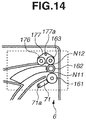
- the second exemplary embodiment is configured to switch the sheet S nip portion from a first nip portion N11 to a second nip portion N12 by using the reversing unit 106 having sub rollers 174 in addition to discharge rollers 161, a drive roller 162, and reversing rollers 163.
- the configuration of the present exemplary embodiment is similar to that according to the first exemplary embodiment except that the sub rollers 174 are provided in the vicinity of the discharge rollers 161 in the reversing unit 106. Therefore, the present exemplary embodiment will be described below centering on the differences from the first exemplary embodiment with reference to Figs. 12 and 13A to 13F . Descriptions of elements similar to those in the first exemplary embodiment will be omitted.
- Fig. 12 is a schematic view illustrating a configuration of the reversing unit 106 when the reversing unit 106 having the sub rollers 174 disposed in the vicinity of the discharge rollers 161 conveys the sheet S.
- a sub roller 174 as an auxiliary rotary member is provided in the vicinity of each discharge roller 161.
- the discharge roller 161 and the sub roller 174 are rotatably held by the discharge roller holder 75 (first holding member) which is movable centering on a fulcrum 75a.
- the discharge roller holder 75 is swingably biased toward the drive roller 162 by the spring 181 as a biasing member provided in the main body 2.
- the discharge roller 161 and the drive roller 162 contact each other to form a first nip portion N11.
- Fig. 13A is a schematic view illustrating a state after the sheet S with an image formed on the first surface is conveyed to the first nip portion N11 and immediately before a moving operation of the drive roller 162 is started.
- the drive roller 162 is rotating in one direction at the initial position (first position) .
- the sheet S is conveyed in the first direction in a state (first state) where the first surface contacts the discharge roller 161 and the sub roller 174 and the second surface contacts the drive roller 162.
- the drive roller 162 starts moving in the direction away from the discharge roller 161 and the reversing roller 163 before the trailing edge Re of the sheet S has been conveyed at the first nip portion N11.
- Fig. 13B is a schematic view illustrating a state where the drive roller 162 starts moving from the initial position.
- the drive roller 162 and the discharge roller 161 contact each other via the sheet S to form a first nip portion N11, and the drive roller 162 and the sub roller 174 contact each other to form a fourth nip portion N14.
- the sheet S is nipped by two different positions (the first nip portion N11 and the fourth nip portion N14) and conveyed in the first direction as the direction of sheet discharge from the reversing unit 106.
- the sub roller 174 is disposed on the upstream side of the discharge roller 161 in the first direction.
- the sheet S is conveyed in a state where the first surface contacts the discharge roller 161 and the sub roller 174 and the second surface contacts drive roller 162.
- Fig. 13C is a schematic view illustrating a state where the drive roller 162 has further moved from the position illustrated in Fig. 13B .
- the discharge roller 161 and the reversing roller 163 contact each other via the sheet S to form a third nip portion N13
- the drive roller 162 and the sub roller 174 contact each other via the sheet S to form a fourth nip portion N14.
- the sheet S is conveyed in the first direction in a state (third state) where the first surface contacts the discharge roller 161 and the sub roller 174, the second surface contacts the drive roller 162 and the reversing roller 163, and the sheet S is nipped by the third nip portion N13 and the fourth nip portion N14.
- the reversing unit 106 when the drive roller 162 moves from the initial state to the retracted position, the sheet S nip state is switched from the first state to the third state by the switching unit.
- Fig. 13D is a schematic view illustrating a sheet S state when the drive roller 162 has moved to the retracted position (second position) where the moving amount of the drive roller 162 is maximized.
- the first nip portion N11 formed by the drive roller 162 and the discharge roller 161 and the fourth nip portion N14 formed by the drive roller 162 and the sub roller 174 are canceled.
- the conveyance of the sheet S is suspended, the sheet S is nipped at the third nip portion N13 formed by the discharge roller 161 and the reversing roller 163, and the sheet S conveyance is held in a suspended state.
- the present exemplary embodiment similar to the first exemplary embodiment, when the drive roller 162 moves from the initial position to the retracted position, the third state where the sheet S is nipped by two different positions is formed. Then, the sheet S is nipped by the third nip portion N13. This prevents the sheet S from dropping from the reversing unit 106 when switching the sheet S nip portion by moving the drive roller 162.
- the drive roller 162 moves to the retracted position, the trailing edge Re of the sheet S nipped at the third nip portion N13 moves above the drive roller 162 having moved to the retracted position due to the self-weight and rigidity of the sheet S or the nipped position and angle of the sheet S at the third nip portion N3. Therefore, the drive roller 162 moves from the lower surface side, i.e., the first surface of the sheet S nipped by the third nip portion N13 to approach the discharge roller 161 and the reversing roller 163, i.e., the drive roller 162 moves from the retracted position to the initial position.
- Fig. 13E is a schematic view illustrating a sheet S state while the drive roller 162 is moving from the retracted position to the initial position.
- the drive roller 162 moves from the lower surface side, i.e., the first surface of the sheet S nipped by the third nip portion N13 to approach the discharge roller 161 and the reversing roller 163, i.e., the drive roller 162 moves from the retracted position to the initial position.
- the drive roller 162 contacts the reversing roller 163 via the sheet S to form a second nip portion N12, and the sheet S is nipped at the second nip portion N12 and the third nip portion N13.
- the reversing roller 163 is driven to rotate by the rotation of the drive roller 162, and the sheet S is conveyed in the second direction opposite to the first direction at the second nip portion N12.
- the sheet S is conveyed in the second direction in a state (third state) where the first surface contacts the discharge roller 161 and the drive roller 162, the second surface contacts the reversing roller 163, and the sheet S is nipped by the second nip portion N12 and the third nip portion N13.
- the drive roller 162 moves to the initial position so as to widen the space between the discharge roller 161 and the reversing roller 163. Then, the third nip portion N13 formed by the contact between the discharge roller 161 and the reversing roller 163 is canceled, and the first nip portion N11 once formed by the contact between the drive roller 162 and the discharge roller 161 is reformed.
- Fig. 13F is a schematic view illustrating a sheet S state when the drive roller 162 has moved to the initial position.
- the sheet S having been held by the third nip portion N13 is nipped by the second nip portion N12 formed by the contact between the drive roller 162 and the reversing roller 163.
- the sheet S is nipped at the second nip portion N12 and conveyed in the second direction in a state (second state) where the first surface contacts the drive roller 162 and the second surface contacts the reversing roller 163.
- the third state where the sheet S is nipped by two different positions (the second nip portion N12 and the third nip portion N13) is formed. Then, the sheet S is nipped by the second nip portion N12. More specifically, in the reversing unit 106, when the drive roller 162 moves from the retracted position to the initial position, the sheet S nip state is switched from the third state to the second state by the switching unit. This prevents the sheet S from dropping from the reversing unit 106 when switching the sheet S nip portion by moving the drive roller 162.
- a switching unit including the drive roller holders 65, the cams 67, the cam shaft 68, and the cam drive unit 69 moves the drive roller 162 to switch the sheet S nip state from the first state to the second state.
- a state of being nipped by two different positions (the third nip portion N13 and the fourth nip portion N14) and a state of being nipped by another two different positions (the second nip portion N12 and the third nip portion N13) are formed.
- the configuration is not limited thereto. Only the state where the sheet S is nipped by two different positions (the third nip portion N13 and the fourth nip portion N14) or only the state where the sheet S is nipped by another two different positions (the second nip portion N12 and the third nip portion N13) may be formed.
- providing the sub rollers 174 enables achieving favorable sheet S conveyance performance when the drive roller 162 moves from the initial position to the retracted position. This is because, in the present exemplary embodiment, the discharge roller 161 and the sub roller 174 contact each other via the sheet S to form a first nip portion N11 and a fourth nip portion N14 when the drive roller 162 moves from the initial position to the retracted position.
- the configuration in which the sheet S is nipped by two different nip portions provides a small curvature of the sheet S compared to the configuration of the first exemplary embodiment in which the sheet S is nipped by another two different positions (the first nip portion N1 and the third nip portion N3). This enables reducing the sheet S conveyance resistance, achieving favorable conveyance performance.
- the present exemplary embodiment will be described below centering on the reversing unit 106 including the sub rollers 174 as auxiliary rotary members on the upstream side of the discharge rollers 161 in the vicinity of the discharge rollers 161 in the first sheet S conveyance direction.
- the configuration is not limited thereto.
- a sub roller 176 as an auxiliary rotary member may be provided in the vicinity of and on the upstream side of the reversing roller 163 in the first sheet S conveyance direction. This configuration also enables acquiring a similar effect to the present exemplary embodiment.
- Figs. 15A to 15G are schematic views illustrating a modification of the present exemplary embodiment in which a sub roller 274 as an auxiliary rotary member is provided on the upstream side of the discharge roller 261, and a sub roller 276 as a second auxiliary rotary member is provided on the upstream side of the reversing roller 263 in the first sheet S conveyance direction.
- the sub rollers 274 and 276 according to the modification are disposed so as to be biased toward a drive roller 262 in a similar configuration to the sub roller 174 according to the present exemplary embodiment.
- the discharge roller 261 and the sub roller 274 are rotatably held by a discharge roller holder 275 (first holding member) which is movable centering on a fulcrum 275a.
- the reversing roller 263 and the sub roller 276 are rotatably held by a reversing roller holder 277 (second holding member) which is movable centering on a fulcrum 277a.
- the discharge roller holder 275 and the reversing roller holder 277 are swingably biased toward the drive roller 262 by springs (not illustrated) as biasing members provided in the main body 2.
- springs not illustrated
- the discharge roller 261 contacts the drive roller 262 to form a first nip portion N21
- the reversing roller 263 contacts the drive roller 262 to form a second nip portion N22.
- Fig. 15A is a schematic view illustrating a state after the sheet S with an image formed on the first surface is conveyed to the first nip portion N21 and immediately before a moving operation of the drive roller 262 is started.
- the drive roller 262 is rotating in one direction at the initial position (first position).
- the sheet S is conveyed in the first direction in a state (first state) where the first surface contacts the discharge roller 261 and the sub roller 274 and the second surface contacts drive roller 262.
- the drive roller 262 starts moving in the direction away from the discharge roller 261 and the reversing roller 263 before the trailing edge Re of the sheet S has been conveyed at the first nip portion N21.
- Fig. 15B is a schematic view illustrating a state where the drive roller 262 starts moving from the initial position.
- the drive roller 262 and the discharge roller 261 contact each other via the sheet S to form a first nip portion N21, and the drive roller 262 and the sub roller 274 contact each other to form a fourth nip portion N24.
- the sheet S is nipped by two different positions (the first nip portion N21 and the fourth nip portion N24) and conveyed in the first direction as the direction of sheet discharge from the reversing unit 206.
- the sub roller 274 is formed on the upstream side of the discharge roller 261 in the first direction.
- the sheet S is conveyed in a state where the first surface contacts the discharge roller 261 and the sub roller 274 and the second surface contacts drive roller 262.
- Fig. 15C is a schematic view illustrating a state where the drive roller 262 has further moved from the position illustrated in Fig. 15B .
- the discharge roller 261 and the reversing roller 263 contact each other via the sheet S to form a third nip portion N23
- the drive roller 262 and the sub roller 274 contact each other via the sheet S to form a fourth nip portion N24.
- the sheet S is conveyed in the first direction in a state (third state) where the first surface contacts the discharge roller 261 and the sub roller 274, the second surface contacts the drive roller 262 and the reversing roller 263, and the sheet S is nipped by the third nip portion N23 and the fourth nip portion N24. More specifically, in the reversing unit 206, when the drive roller 262 moves from the initial state to the retracted position, the sheet S nip state is switched from the first state to the third state by the switching unit.
- Fig. 15D is a schematic view illustrating a sheet S state when the drive roller 262 has moved to the retracted position (second position) where the moving amount of the drive roller 262 is maximized.
- the drive roller 262 moves from the initial position to the retracted position as illustrated in Fig. 15D , the first nip portion N21 formed by the drive roller 262 and the discharge roller 261 and the fourth nip portion N24 formed by the drive roller 262 and the sub roller 274 are canceled.
- the discharge roller 261 and the reversing roller 263 contact each other via the sheet S to form a third nip portion N23, the sheet S is nipped at the third nip portion N23, and the conveyance of the sheet S is held in a suspended state.
- the trailing edge Re of the sheet S nipped at the third nip portion N23 moves above the drive roller 262 having moved to the retracted position due to the self-weight and rigidity of the sheet S or the nipped position and angle of the sheet S at the third nip portion N23.
- the drive roller 262 therefore, moves from the lower surface side, i.e., the first surface of the sheet S nipped by the third nip portion N23 to approach the discharge roller 261 and the reversing roller 263, i.e., the drive roller 262 moves from the retracted position to the initial position.
- Fig. 15E is a schematic view illustrating a sheet S state while the drive roller 262 is moving from the retracted position to the initial position.
- the drive roller 262 moves from the lower surface side, i.e., the first surface of the sheet S nipped by the third nip portion N23 to approach the discharge roller 261 and the reversing roller 263, i.e., the drive roller 262 moves from the retracted position to the initial position.
- the drive roller 262 contacts the sub roller 276 via the sheet S to form a fifth nip portion N25, and the sheet S is nipped at the fifth nip portion N25 and the third nip portion N23.
- the sub roller 276 is driven to rotate by the rotation of the drive roller 262, and the sheet S is conveyed at the fifth nip portion N25 in the second direction opposite to the first direction. Therefore, the sheet S is conveyed in the second direction in a state (third state) where the first surface contacts the discharge roller 261 and the drive roller 262 and the second surface contacts sub roller 276 and the reversing roller 263.
- Fig. 15F is a schematic view illustrating a state where the drive roller 262 has further moved from the position illustrated in Fig. 15E .
- the drive roller 262 and the sub roller 276 contact each other via the sheet S to form a fifth nip portion N25, and the drive roller 262 and the reversing roller 263 contact each other to form a second nip portion N22.
- the sheet S is conveyed in the second direction being nipped by two different positions (the fifth nip portion N25 and the second nip portion N22).
- the sheet S is conveyed in a state where the first surface contacts the drive roller 262 and the second surface contacts sub roller 276 and the reversing roller 263.
- Fig. 15G is a schematic view illustrating a sheet S state when the drive roller 262 has moved to the initial position.
- the sheet S having been held by the third nip portion N23 is nipped by the second nip portion N22 formed by the contact between the drive roller 262 and the reversing roller 263.
- the sheet S nip state is switched from the third state to the second state by the switching unit.
- the sheet S is nipped at the second nip portion N22 and conveyed in the second direction in a state (second state) where the first surface contacts the drive roller 262 and the second surface contacts the reversing roller 263.
- the configuration of the modification enables acquiring a similar effect to the present exemplary embodiment. Further, in the configuration of the modification, providing a plurality of auxiliary rotating members enables reducing the conveyance resistance of the Sheet S both when the drive roller 262 moves from the initial position to the retracted position and when the drive roller 262 moves from the retracted position to the initial position. This enables improving the conveyance performance of the sheet S.
- a third exemplary embodiment will be described below.
- the first exemplary embodiment has been described above centering on a configuration for switching the sheet S nip portion from the first nip portion N1 to the second nip portion N2 by moving the drive roller 62.
- the third exemplary embodiment will be described below centering on a configuration for switching the sheet S nip portion from the first nip portion N1 to the second nip portion N2 by moving a discharge roller 361 in a reversing unit 306 or moving a reversing roller 463 in a reversing unit 406.
- the configuration of the present exemplary embodiment is similar to that according to the first exemplary embodiment except the configurations of the reversing units 306 and 406, except that the discharge roller 361 is moved in the reversing unit 306, and except that the reversing roller 463 is moved in the reversing unit 406.
- the present exemplary embodiment therefore, will be described below centering on differences from the first exemplary embodiment, and descriptions of elements similar to those in the first exemplary embodiment will be omitted.
- a configuration of the reversing unit 306 for switching the sheet S nip portion by moving the discharge roller 361 will be described below with reference to Figs. 16A, 16B , 17A, 17B , and 18A to 18E .
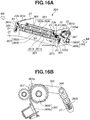
- Fig. 16A is a schematic view illustrating a configuration of the reversing unit 306 according to the present exemplary embodiment when viewed from the downstream side in the sheet conveyance direction.
- a drive roller 362 (first rotary member) is composed of a shaft 362a and rubber contact portions 362b
- a reversing roller 363 (third rotary member) is composed of a shaft 363a and rubber contact portions 363b.
- the discharge roller 361 (second rotary member) is composed of a shaft 361a and rollers 361b.
- the rollers 361b are formed on the shaft 361a as the discharge roller 361, the shaft 361a and the rollers 361b may be integrally formed as the discharge roller 361.
- the drive roller 362 is rotatably held by a frame 23 of the main body 2.
- the drive roller 362 with one end connected to a gear 70 rotates while receiving a driving force from the drive motor 90 as a driving source via the gear 70. Since the drive motor 90 rotates in one direction, the drive roller 362 also rotates in one direction.
- the discharge roller 361 is rotatably held on both ends by discharge roller bearings 361c provided in engagement slots 365b of discharge roller holders 365 which are rotatable centering on fulcrums 366.
- the discharge roller 361 is biased toward the drive roller 362 by springs 81 (first biasing members) via the discharge roller bearings 361c, and a first nip portion N31 is formed by the discharge roller 361 and the drive roller 362 pressed by the discharge roller 361.
- the discharge roller holder 365 is provided with an engagement slot 365b for supporting the discharge roller 361 on one side of the fulcrum 366 and a guide groove 365a on the other side.
- the reversing roller 363 is rotatably held by reversing roller bearings 363c movably held along with guide holes 23a provided on the frames 23 of the main body 2.
- the reversing roller 363 is biased toward the drive roller 362 by springs 83 (second biasing members) via the reversing roller bearings 363c, and a second nip portion N32 is formed by the reversing roller 363 and the drive roller 362 pressed by the reversing roller 363.
- a cam shaft 368 is disposed to face the drive roller 362 in approximately parallel with the drive roller 362. Both ends of the cam shaft 368 are provided with cams 367 which are integrally rotatable with the cam shaft 368 via the frames 23. Each cam 367 has a cylindrical protruding portion 367a on the surface different from the surface holding the cam shaft 368. When the protruding portion 367a engages with the guide groove 365a, the cam 367 is held by the discharge roller holder 365.
- One end of the cam shaft 368 is provided with a cam drive unit 369 (formed of a solenoid 369a as a changeover member, and a partially-toothless gear 369b) that can turn the drive for rotating the cam 367 ON and OFF.
- Fig. 16B is a schematic view illustrating a configurations of the discharge roller holder 365 and the cam drive unit 369 when viewed from the direction of the arrow BB illustrated in Fig. 16A .
- the partially-toothless gear 369b is provided with two different partially-toothless portions
- the solenoid 369a is provided with an engagement portion that can engage with the partially-toothless portions of the partially-toothless gear 369b.
- the partially-toothless gear 369b is configured to stop at two different positions at predetermined angular intervals in one revolution by turning the solenoid 369a ON and OFF.
- FIG. 17A is a schematic view illustrating a configuration of the reversing unit 306 before the moving operation of the discharge roller 361 is performed according to the present exemplary embodiment.
- Fig. 17B is a schematic view illustrating a configuration of the reversing unit 306 after the moving operation of the discharge roller 361 is performed according to the present exemplary embodiment.
- Figs. 17A and 17B are schematic views illustrating the reversing unit 306 illustrated in Fig. 16A when viewed from the direction of the arrow AA.
- the discharge roller 361 and the drive roller 362 contact each other to form a first nip portion N31, and the reversing roller 363 and the drive roller 362 contact each other to form a second nip portion N32.
- the discharge roller 361 has not yet started the moving operation.
- the position of the discharge roller 361 illustrated in Fig. 17A is assumed as the initial position (first position).
- the engagement portion of the solenoid 369a engages with the first partially-toothless portion of the partially-toothless gear 369b, the partially-toothless gear 369b is locked with the drive canceled, and the cam 367 stops without rotating.
- the cam 367 rotates in the direction of the arrow A, as illustrated in Fig. 17A .
- the protruding portion 367a engaging with the guide groove 365a of the discharge roller holder 365 also starts rotating in the direction of the arrow A.
- the discharge roller holder 365 rotates in the direction of the arrow B centering on the fulcrum 366, and the discharge roller 361 supported on both ends by the discharge roller bearings 361c provided on the discharge roller holders 365 starts moving.
- Fig. 17B illustrates the position of the discharge roller 361 when the discharge roller 361 moves by the rotation of the cam 367 and contacts the reversing roller 363.
- the position of the discharge roller 361 at this timing is assumed as a reversing position (second position).
- the second partially-toothless portion of the partially-toothless gear 369b reaches the position where the second partially-toothless portion engages with the engagement portion of the solenoid 369a.
- the solenoid 369a has already been turned OFF, the second partially-toothless portion of the partially-toothless gear 369b engages with the engagement portion of the solenoid 369a, the partially-toothless gear 369b is locked with the drive canceled, and the cam 367 stops rotating. Accordingly, the rotation of the discharge roller holder 365 stops, and the discharge roller 361 stops at the reversing position.
- the solenoid 369a has already been turned OFF, the first partially-toothless portion of the partially-toothless gear 369b engages with the engagement portion of the solenoid 369a, the partially-toothless gear 369b is locked with the drive canceled, and the cam 367 stops rotating.
- the discharge roller 361 moves from the reversing position to the initial position, and then stops moving at the initial position.
- the discharge roller 361 moves from the reversing position, the discharge roller 361 and the drive roller 362 contact each other again to form a first nip portion N31.
- the above-described sequential moving operation of the reversing roller 363 is performed while the cam 367 makes one revolution by the cam drive unit 369.
- FIGS. 18A to 18E are schematic views illustrating the reversing unit 306 illustrated in Fig. 16A when viewed from the direction of the arrow BB.
- Fig. 18A is a sectional view schematically illustrating the reversing unit 306 before a moving operation of the discharge roller 361 is performed, when viewed from the axial direction of the discharge roller 361.
- the discharge roller 361 and the drive roller 362 contact each other to form a first nip portion N31, and the discharge roller 361 is rotating while receiving a rotary force from the drive roller 362 rotating in the direction of the arrow R1.
- the sheet S is conveyed in the first direction as the direction of sheet discharge from the main body 2 in a state (first state) where the first surface contacts the discharge roller 361 and the second surface contacts the drive roller 362 at the first nip portion N31.
- a second nip portion N32 is formed at the position where the reversing roller 363 and the drive roller 362 contact each other, and the reversing roller 363 is rotating while receiving a rotary force from the drive roller 362 rotating in the direction of the arrow R1. This enables conveying, at the second nip portion N32, the sheet S in the second direction opposite to the sheet S conveyance direction at the first nip portion N31.
- the discharge roller 361 starts the moving operation before the trailing edge Re of the sheet S conveyed in the first direction has been conveyed at the first nip portion N31, and moves in the direction of the arrow B1 from the initial position to the reversing position.
- Fig. 18B is a sectional view schematically illustrating the reversing unit 306 when the discharge roller 361 has moved from the initial position to the reversing position, when viewed from the axial direction of the discharge roller 361.
- a third nip portion N33 is formed by the discharge roller 361 and the reversing roller 363.
- the discharge roller 361 and the drive roller 362 contact each other to form a first nip portion N31.
- the sheet S is nipped by the first nip portion N31 and the third nip portion N33 and conveyed in the first direction in a state (third state) where the first surface contacts the discharge roller 361, and the second surface contacts the drive roller 362 and the reversing roller 363. More specifically, in the reversing unit 306, when the discharge roller 361 moves from the initial state to the reversing position, the sheet S nip state is switched from the first state to the third state by the switching unit.
- Fig. 18C is a sectional view schematically illustrating the reversing unit 306 when the sheet S has been further conveyed from the state illustrated in Fig. 18B , when viewed from the axial direction of the discharge roller 361.
- the trailing edge Re of the sheet S passes through the first nip portion N31 formed by the drive roller 362 and the discharge roller 361, and the sheet S conveyance is suspended.
- the sheet S having been conveyed in the first direction at the first nip portion N1 is then nipped only by the third nip portion N33 formed by the discharge roller 361 and the reversing roller 363, and the sheet S conveyance is held in a suspended state.
- the third state where the sheet S is nipped by two different positions (the first nip portion N31 and the third nip portion N33) is formed. Then, the sheet S is nipped by the third nip portion N33. This prevents the sheet S from dropping from the reversing unit 306 when switching the sheet S nip portion by moving the discharge roller 361.
- Fig. 18D is a sectional view schematically illustrating the reversing unit 306 when the discharge roller 361 moves from the reversing position to the initial position, when viewed from the axial direction of the discharge roller 361.
- the discharge roller 361 moves in the direction of the arrow C1 while in contact with the drive roller 362.
- the reversing roller 363 rotates while receiving a rotary force from the drive roller 362 rotating in the direction of the arrow R1, and the sheet S is conveyed in the second direction at the second nip portion N32.
- Fig. 18E is a sectional view schematically illustrating the reversing unit 306 when the discharge roller 361 has moved from the reversing position to the initial position, and the above-described sequential moving operation of the discharge roller 361 is completed, when viewed from the axial direction of the discharge roller 361.
- the discharge roller 361 moves in the direction of the arrow C1 from the reversing position to the initial position, the third nip portion N33 is canceled, and the sheet S is nipped at the second nip portion N32 formed by the drive roller 362 and the reversing roller 363.
- the sheet S is conveyed in the second direction in a state (second state) where the sheet S is nipped at the second nip portion N32, the first surface contacts the drive roller 362, and the second surface contacts the reversing roller 363. More specifically, in the reversing unit 306, when the discharge roller 361 moves from the reversing state to the initial position, the sheet S nip state is switched from the third state to the second state by the switching unit.
- the switching unit including the discharge roller holders 365, the cams 367, the cam shaft 368, and the cam drive units 369 moves the reversing roller 363 to switch the sheet S nip state from the first state to the second state.
- the configuration of the present exemplary embodiment also makes it possible to acquire a similar effect to the first exemplary embodiment.
- a configuration of the reversing unit 406 capable of switching the sheet S nip portion by moving the reversing roller 463 will be described below with reference to Figs. 19 , 20A , 20B , and 21A to 21D .
- Fig. 19 is a schematic view illustrating a configuration of the reversing unit 406 according to the present exemplary embodiment when viewed from the downstream side in the sheet conveyance direction.
- a drive roller 462 (first rotary member) is composed of a shaft 462a and rubber contact portions 462b
- the reversing roller 463 (second rotary member) is composed of a shaft 463a and rubber contact portions 463b.
- a discharge roller 461 (third rotary member) is composed of a shaft 461a and rollers 461b made of synthetic resin.
- the rollers 461b are formed on the shaft 461a as the discharge roller 461, the shaft 461a and the rollers 461b may be integrally formed as the discharge roller 461.
- the discharge roller 461 is rotatably held by discharge roller bearings 461c movably held along with guide holes 23a provided on the frames 23 of the main body 2.
- the discharge roller 461 is biased toward the drive roller 462 by springs 81 (first biasing members) via the discharge roller bearings 461c.
- springs 81 first biasing members
- the drive roller 462 is rotatably held by the frames 23.
- the drive roller 462 with one end connected to a gear 70 rotates while receiving a driving force from the drive motor 90 as a driving source via the gear 70. Since the drive motor 90 rotates in one direction, the drive roller 462 also rotates in one direction.
- the reversing roller 463 is rotatably held on both ends by reversing roller bearings 463c provided in engagement slots 465b of reversing roller holders 465 which are rotatable centering on fulcrums 466.
- the reversing roller 463 is biased toward the drive roller 462 by springs 83 (second biasing members) via the reversing roller bearings 463c.
- the inverting roller holder 465 includes an engagement slot 465b for supporting the inverting roller 463 on one side of the fulcrum 466, and a guide groove 465a on the other side.
- a cam shaft 468 is disposed to face the drive roller 462 in approximately parallel with the drive roller 462. Both ends of the cam shaft 468 are provided with cams 467 which are integrally rotatable around the cam shaft 468.
- Each cam 467 has a cylindrical protruding portion 467a on the surface different from the surface holding the cam shaft 468. When the protruding portion 467a engages with the guide groove 465a, the cam 467 is held by the discharge roller holder 465.
- One end of the cam shaft 468 is provided with a cam drive unit 469 (formed of a solenoid 469a as a changeover member, and a partially-toothless gear 469b) that can turn the drive for rotating the cam 467 ON and OFF.
- a cam drive unit 469 formed of a solenoid 469a as a changeover member, and a partially-toothless gear 469b
- the partially-toothless gear 469b is provided with two different partially-toothless portions
- the solenoid 469a is provided with an engagement portion that can engage with the partially-toothless portions of the partially-toothless gear 469b.
- the partially-toothless gear 469b is configured to stop at two different positions at predetermined angular intervals in one revolution by turning the solenoid 469a ON and OFF.
- FIG. 20A is a schematic view illustrating a configuration of the reversing unit 406 before the moving operation of the reversing roller 463 is performed according to the present exemplary embodiment.
- Fig. 20B is a schematic view illustrating a configuration of the reversing unit 406 after the moving operation of the reversing roller 463 is performed according to the present exemplary embodiment.
- Figs. 20A and 20B are schematic views illustrating the reversing unit 406 illustrated in Fig. 19 when viewed from the direction of the arrow AA.
- the discharge roller 461 contacts the drive roller 462 to form a first nip portion N41, and the reversing roller 463 contacts the drive roller 462 to form a second nip portion N42.
- the discharge roller 461 has not yet started the moving operation in the state illustrated in Fig. 20A .
- the position of the reversing roller 463 illustrated in Fig. 20A is assumed as the initial position (first position).
- the engagement portion of the solenoid 469a engages with the first partially-toothless portion of the partially-toothless gear 469b, the partially-toothless gear 469b is locked with the drive canceled, and the cam 467 stops without rotating.
- the solenoid 469a is turned ON to unlock the partially-toothless gear 469b, the cam 467 rotates in the direction of the arrow D, as illustrated in Fig. 20A .
- the protruding portion 467a engaging with the guide groove 465a of the inverting roller holder 465 also starts rotating in the direction of the arrow D.
- the reversing roller holders 465 rotate in the direction of the arrow E centering on the fulcrums 466, and the reversing roller 463 supported on both ends by the reversing roller bearings 463c provided in the reversing roller holders 465 starts moving.
- Fig. 20B illustrates the position of the reversing roller 463 when the reversing roller 463 moves by the rotation of the cam 467 and contacts the discharge roller 461.
- the position of the reversing roller 463 at this timing is assumed as the reversing position (second position).
- the second partially-toothless portion of the partially-toothless gear 469b reaches the position where the second partially-toothless portion engages with the engagement portion of the solenoid 469a.
- the solenoid 469a has already been turned OFF.
- the second partially-toothless portion of the partially-toothless gear 469b engages with the engagement portion of the solenoid 469a, the partially-toothless gear 469b is locked with the drive canceled, and the cam 467 stops rotating. Accordingly, the rotation of the reversing roller holders 465 stops, and the reversing roller 463 stops at the reversing position.
- the solenoid 469a has already been turned OFF. Therefore, the first partially-toothless portion of the partially-toothless gear 469b engages with the engagement portion of the solenoid 469a, the partially-toothless gear 469b is locked with the drive canceled, and the cam 467 stops rotating.
- the reversing roller 463 moves from the reversing position to the initial position, and then stops moving at the initial position.
- the discharge roller 461 and the drive roller 462 contact each other again to form a first nip portion N41.
- the above-described sequential moving operation of the reversing roller 463 is performed while the cam 467 makes one revolution by the cam drive unit 469.
- FIGS. 21A to 21E are schematic views illustrating the reversing unit 406 illustrated in Fig. 19 when viewed from the direction of the arrow BB.
- Fig. 21A is a sectional view schematically illustrating the reversing unit 406 before a moving operation of the reversing roller 463 is performed, when viewed from the axial direction of the reversing roller 463.
- the discharge roller 461 and the drive roller 462 contact each other to form a first nip portion N41, and the discharge roller 461 is rotating while receiving a rotary force from the drive roller 462 rotating in the direction of the arrow R1.
- the sheet S is conveyed in the first direction as the direction of sheet discharge from the main body 2 in a state (first state) where the first surface contacts the discharge roller 461 and the second surface contacts the drive roller 462 at the first nip portion N41.
- a second nip portion N42 is formed at the position where the reversing roller 463 and the drive roller 462 contact each other, and the reversing roller 463 is rotating while receiving a rotary force from the drive roller 462 rotating in the direction of the arrow R1. This enables conveying, at the second nip portion N42, the sheet S in the second direction opposite to the sheet S conveyance direction at the first nip portion N41.
- the reversing roller 463 starts the moving operation before the trailing edge Re of the sheet S conveyed in the first direction has been conveyed at the first nip portion N41, and moves in the direction of the arrow E1 from the initial position to the reversing position.
- Fig. 21B is a sectional view schematically illustrating the reversing unit 406 when the reversing roller 463 has moved from the initial position to the reversing position, when viewed from the axial direction of the reversing roller 463.
- a third nip portion N43 is formed by the reversing roller 463 and the discharge roller 461.
- the discharge roller 461 and the drive roller 462 contact each other to form the first nip portion N41.
- the sheet S is nipped by the first nip portion N41 and the third nip portion N43 and conveyed in the first direction in a state (third state) where the first surface contacts the discharge roller 461, and the second surface contacts the drive roller 462 and the reversing roller 463. More specifically, in the reversing unit 406, when the reversing roller 463 moves from the initial state to the reversing position, the sheet S nip state is switched from the first state to the third state by the switching unit.
- Fig. 21C is a sectional view schematically illustrating the reversing unit 406 when the sheet S has been further conveyed from the state illustrated in Fig. 21B , when viewed from the axial direction of the reversing roller 463.
- the trailing edge Re of the sheet S passes through the first nip portion N41 formed by the drive roller 462 and the discharge roller 461, and the sheet S conveyance is suspended.
- the sheet S having been conveyed in the first direction at the first nip portion N41 is then nipped only by the third nip portion N43 formed by the discharge roller 461 and the reversing roller 463, and the sheet S conveyance is held in a suspended state.
- the third state where the sheet S is nipped by two different positions (the first nip portion N41 and the third nip portion N43) is formed. Then, the sheet S is nipped by the third nip portion N43. This prevents the sheet S from dropping from the reversing unit 406 when switching the sheet S nip portion by moving the reversing roller 463.
- Fig. 21D is a sectional view schematically illustrating the reversing unit 406 when the reversing roller 463 moves from the reversing position to the initial position, when viewed from the axial direction of the reversing roller 463.
- the reversing roller 463 moves in the direction of the arrow F1 while in contact with the drive roller 462.
- the reversing roller 463 contacts the drive roller 462 to form a second nip portion N42
- the reversing roller 463 rotates while receiving a rotary force from the drive roller 462 rotating in the direction of the arrow R1, and the sheet S is conveyed in the second direction at the second nip portion N42.
- Fig. 21E is a sectional view schematically illustrating the reversing unit 406 when the reversing roller 463 has moved from the reversing position to the initial position, and the above-described sequential moving operation of the reversing roller 463 is completed, when viewed from the axial direction of the reversing roller 463.
- the reversing roller 463 moves in the direction of the arrow F1 from the reversing position to the initial positions, the third nip portion N43 is canceled, and the sheet S is nipped at the second nip portion N42 formed by the drive roller 462 and the reversing roller 463.
- the sheet S is conveyed in the second direction in a state (second state) where the sheet S is nipped at the second nip portion N42, the first surface contacts the drive roller 462, and the second surface contacts the reversing roller 463. More specifically, in the reversing unit 406, when the reversing roller 463 moves from the reversing state to the initial position, the sheet S nip state is switched from the third state to the second state by the switching unit.
- the switching unit including the reversing roller holders 465, the cams 467, the cam shaft 468, and the cam drive units 469 moves the reversing roller 463 to switch the sheet S nip state from the first state to the second state.
- the configuration of the present exemplary embodiment also makes it possible to acquire a similar effect to the first exemplary embodiment.
- the present invention is not limited thereto.
- the present invention may be applied to other than an electrophotographic image forming apparatus, such as an ink-jet image forming apparatus.
Landscapes
- Physics & Mathematics (AREA)
- General Physics & Mathematics (AREA)
- Engineering & Computer Science (AREA)
- Mechanical Engineering (AREA)
- Separation, Sorting, Adjustment, Or Bending Of Sheets To Be Conveyed (AREA)
- Delivering By Means Of Belts And Rollers (AREA)
Abstract
Description
- The present invention relates to a sheet conveying apparatus for continuously conveying sheets, and an image forming apparatus, such as a copying apparatus, a printer, and a facsimile, having the sheet conveying apparatus.
- With the recent increase in demand for further resource saving on image forming apparatuses, the frequency of utilizing two-sided printing on such sheets as paper, overhead projector (OHP) sheets, plastic sheets, and cloths is increasing. Therefore, with an image forming apparatus having a two-sided printing function, importance is attached to the improvement in the number of sheets output per unit time or the productivity in two-sided printing.
- As a conventional technique, Japanese Patent Application Laid-Open No.
2015-083353 - The reversing unit discussed in Japanese Patent Application Laid-Open No.
2015-083353 - More specifically, in the configuration discussed in Japanese Patent Application Laid-Open No.
2015-083353 - However, in the configuration discussed in Japanese Patent Application Laid-Open No.
2015-083353 - The present invention is directed to a sheet conveying apparatus capable of switching the nip portion for nipping a sheet before the trailing edge of the sheet in the sheet conveyance direction has been completely discharged from a first nip portion. Each of the embodiments of the present invention described below can be implemented solely or as a combination of a plurality of the embodiments. Also, features from different embodiments can be combined where necessary or where the combination of elements or features from individual embodiments in a single embodiment is beneficial.
- According to a first aspect of the present invention, there is provided a sheet conveying apparatus as specified in claims 1 to 14. According to a second aspect of the present invention, there is provided an image forming apparatus as specified in claim 15.
- Further features of the present invention will become apparent from the following description of exemplary embodiments with reference to the attached drawings.
-
-
Fig. 1 is a sectional view schematically illustrating an overall configuration of an image forming apparatus according to a first exemplary embodiment. -
Fig. 2 is a sectional view schematically illustrating a reversing unit according to the first exemplary embodiment. -
Fig. 3 is a schematic view illustrating a configuration of the reversing unit according to the first exemplary embodiment. -
Fig. 4 is a schematic view illustrating a configuration of rotary members of the reversing unit according to the first exemplary embodiment. -
Fig. 5 is a block diagram illustrating drive control according to the first exemplary embodiment. -
Figs. 6A, 6B, and 6C are schematic views illustrating a configuration of the reversing unit and an operation of a drive roller according to the first exemplary embodiment. -
Fig. 7 is a sectional view schematically illustrating a sheet conveyance operation in two-sided printing according to the first exemplary embodiment. -
Fig. 8 is a sectional view schematically illustrating another sheet conveyance operation in two-sided printing according to the first exemplary embodiment. -
Fig. 9 is a sectional view schematically illustrating still another sheet conveyance operation in two-sided printing according to the first exemplary embodiment. -
Fig. 10 is a sectional view schematically illustrating still another sheet conveyance operation in two-sided printing according to the first exemplary embodiment. -
Figs. 11A, 11B, 11C, 11D, and 11E are schematic views illustrating a moving operation of the drive roller according to the first exemplary embodiment. -
Fig. 12 is a schematic view illustrating a configuration of a reversing unit according to a second exemplary embodiment. -
Figs. 13A, 13B, 13C, 13D, 13E, and 13F are schematic views illustrating a moving operation of the drive roller according to the second exemplary embodiment. -
Fig. 14 is a schematic view illustrating another configuration of the reversing unit according to the second exemplary embodiment. -
Figs. 15A, 15B, 15C, 15D, 15E, 15F, and 15G are schematic views illustrating a moving operation of the drive roller in the reversing unit according to a modification of the second exemplary embodiment. -
Figs. 16A and 16B are schematic views illustrating a configuration of a reversing unit according to a third exemplary embodiment. -
Figs. 17A and 17B are schematic views illustrating a configuration of the reversing unit and an operational mechanism of a discharge roller according to the third exemplary embodiment. -
Figs. 18A, 18B, 18C, 18D, and 18E are schematic views illustrating a moving operation of the discharge roller according to the third exemplary embodiment. -
Fig. 19 is a schematic view illustrating another configuration of the reversing unit according to the third exemplary embodiment. -
Figs. 20A and 20B are schematic views illustrating another configuration of the reversing unit and an operation of the reversing roller according to the third exemplary embodiment. -
Figs. 21A, 21B, 21C, 21D, and 21E are schematic views illustrating another configuration and a moving operation of the reversing roller according to the third exemplary embodiment. - Exemplary embodiments of the present invention will be described in detail below with reference to the accompanying drawings. The following exemplary embodiments will be described centering on an example using a laser beam printer having a sheet conveying apparatus of the present invention. Components according to the following exemplary embodiments are to be considered as illustrative and not restrictive of the scope of the present invention.
- A first exemplary embodiment will be described below.
Fig. 1 is a sectional view schematically illustrating a configuration of an image forming apparatus 1 having the sheet conveying apparatus of the present invention. As illustrated inFig. 1 , the image forming apparatus 1 includes amain body 2 of the image forming apparatus 1, afeed unit 3, animage forming unit 4, aconveyance unit 5, a reversingunit 6, and acontrol unit 7. - The
main body 2 includes thefeed unit 3, theimage forming unit 4, theconveyance unit 5, the reversingunit 6, and thecontrol unit 7. Asheet supplying cassette 21 as an accommodation unit is detachably attached on the upstream side of thefeed unit 3 in the sheet conveyance direction. Thesheet supplying cassette 21 feeds unprinted sheets S stored therein in a stacked state. When printing on a sheet S is completed, the sheet S is discharged onto adischarge tray 22 serving as a stacking unit for stacking sheets discharged from themain body 2. Thedischarge tray 22 is formed on the downstream side of the reversingunit 6 in the sheet conveyance direction. - The
feed unit 3 includes afeed roller 30 and aseparation portion 31 formed of aseparation pad 31a and aseparation holder 31b for holding theseparation pad 31a. Theseparation pad 31a is in pressure contact with thefeed roller 30. The sheets S stored in thesheet supplying cassette 21 are fed to theseparation portion 31 by the rotation of thefeed roller 30. After the sheets S are separated one by one by theseparation portion 31, a sheet S is fed to afirst conveyance path 50. - The
image forming unit 4 includes aphotosensitive drum 40 as an image bearing member, alaser scanner unit 41, adevelopment unit 42, atransfer roller 43, and a fixingunit 44. Thelaser scanner unit 41 irradiates thephotosensitive drum 40 uniformly charged by a charging unit (not illustrated) based on image information. Then, an electrostatic latent image is formed on the surface of thephotosensitive drum 40. Thedevelopment unit 42 develops the electrostatic latent image to form a toner image on the surface of thephotosensitive drum 40. Thetransfer roller 43 transfers the developed toner image onto the sheet S. The fixingunit 44 heats and pressurizes the sheet S to fix the toner image onto the sheet S. In this way, an image is formed on the sheet S in theimage forming unit 4. -
Fig. 2 is a sectional view schematically illustrating a configuration of the reversingunit 6 according to the present exemplary embodiment. The configuration of the reversingunit 6 will be described below with reference toFig. 2 . The reversingunit 6 includes a drive roller 62 (first rotary member) rotating in one direction (in the direction of the arrow R1) while receiving a driving force from a driving source, a discharge roller 61 (second rotary member) driven by the rotation of thedrive roller 62, and a reversing roller 63 (third rotary member). - The
discharge roller 61 contacts thedrive roller 62 to form a first nip portion N1 at which thedischarge roller 61 nips and conveys the sheet S together with thedrive roller 62. The reversingroller 63 contacts thedrive roller 62 at a position different from the position of thedischarge roller 61 in the circumferential direction of thedrive roller 62 to form a second nip portion N2 at which the reversingroller 63 nips and conveys the sheet S together with thedrive roller 62. - When the
drive roller 62 rotates, thedrive roller 62 and thedischarge roller 61 convey the sheet S from thedrive roller 62 to thedischarge tray 22 and then discharge the sheet S from the first nip portion N1. The direction in which the sheet S is discharged from the first nip portion N1 to thedischarge tray 22 is referred to as a discharge direction (first direction) . Thedrive roller 62 is rotating in one direction while receiving a driving force. Therefore, at the second nip portion N2, the sheet S is conveyed from thedischarge tray 22 to thesecond conveyance path 51 in the second direction different from the sheet conveyance direction at the first nip portion N1. The direction in which the sheet S having been conveyed in the discharge direction toward thedischarge tray 22 is conveyed from thedischarge tray 22 to the reversingunit 6 is referred to as a reversing direction (second direction). - In other words, when the
drive roller 62 rotates in one direction (in the direction of the arrow R1), the sheet S is conveyed in the first direction at the first nip portion N1 and conveyed in the second direction opposite to the first direction at the second nip portion N2. When the reversingunit 6 moves thedischarge roller 61, the sheet S nip state is switched from the state of being nipped by the first nip portion N1 to the state of being nipped by the second nip portion N2. A moving operation of thedischarge roller 61 for switching the sheet S nip state will be described in detail below. - As illustrated in
Fig. 1 , theconveyance unit 5 includes afirst conveyance path 50, asecond conveyance path 51, aconveyance roller pair 52, are-conveyance roller pair 53, afirst sensor 54, and asecond sensor 55. - The
first conveyance path 50 is used to convey the sheet S to theimage forming unit 4 to reform an image on the sheet S conveyed from thesheet supplying cassette 21 and the sheet S conveyed in the reversing direction by the reversingunit 6. The downstream side of thefirst conveyance path 50 is connected to the first nip portion N1 of the reversingunit 6, and the upstream side of thefirst conveyance path 50 is divided into two paths in the sheet S conveyance direction. One of the two division paths of thefirst conveyance path 50 is connected to thesheet supplying cassette 21. The sheet S is fed from thesheet supplying cassette 21 to thefirst conveyance path 50. In theimage forming unit 4, a toner image is transferred onto the sheet S by thetransfer roller 43. The other of the two division paths of thefirst conveyance path 50 is connected to thesecond conveyance path 51 for re-conveying to thefirst conveyance path 50 the sheet S conveyed in the reversing direction by the reversingunit 6. The upstream side of thesecond conveyance path 51 is connected to the second nip portion N2 of the reversingunit 6, and the downstream side of thesecond conveyance path 51 is connected to the other of the two division paths of thefirst conveyance path 50 in the sheet conveyance direction. - The
conveyance roller pair 52 disposed in thefirst conveyance path 50 conveys along thefirst conveyance path 50 the sheet S fed or conveyed in thefirst conveyance path 50. There-conveyance roller pair 53 disposed in thesecond conveyance path 51 conveys to thefirst conveyance path 50 the sheet S conveyed in thesecond conveyance path 51. - The
first sensor 54 disposed between thefeed unit 3 and theimage forming unit 4 in thefirst conveyance path 50 detects the positions of the leading and trailing edges of the sheet S passing through thefirst sensor 54. Thesecond sensor 55 disposed on the downstream side of thefirst conveyance path 50 in the sheet conveyance direction detects the positions of the leading and trailing edges of the sheet S passing through thesecond sensor 55, similar to thefirst sensor 54. Each of thefirst sensor 54 and thesecond sensor 55 according to the present exemplary embodiment includes a sensor flag (not illustrated) biased in the direction of contact with the sheet S and rotated by the passage of the sheet S, and a photo-interrupter (not illustrated) as an optical sensor. In such a configuration, when the sheet S passes through each sensor, the sensor flag is pushed down and rotated to block or open the detection area of the photo-interrupter, making it possible to detect the leading and trailing edges of the sheet S. - Although, in the present exemplary embodiment, the
first sensor 54 and thesecond sensor 55 include a sensor flag which is rotated by the passage of the sheet S, a sensor for detecting the leading and trailing edges of the sheet S is not limited thereto. For example, thefirst sensor 54 and thesecond sensor 55 may be an optical sensor for detecting the presence or absence of the sheet S. In this case, a light emitting element irradiates the sheet S with light and a light receiving element receives penetrated or reflected light. - The
control unit 7 controls the drive related to the sheet S conveyance, such as thefeed roller 30, theconveyance roller pair 52, there-conveyance roller pair 53, and the reversingunit 6, and controls moving operations of thedischarge roller 61 in the reversingunit 6. Control of operations of the reversingunit 6 by thecontrol unit 7 will be described in detail below. - A configuration of the reversing
unit 6 according to the present exemplary embodiment will be described below with reference toFigs. 3 to 5 .Fig. 3 is a schematic view illustrating a configuration of the reversingunit 6 according to the present exemplary embodiment when viewed from the downstream side in the sheet conveyance direction.Fig. 4 is a schematic view illustrating a configurations of thedischarge rollers 61, thedrive roller 62, and the reversingrollers 63 according to the present exemplary embodiment.Fig. 5 is a block diagram illustrating drive control according to the present exemplary embodiment. - As illustrated in
Fig. 3 , in the reversingunit 6, both ends of thedrive roller 62 are rotatably held bydrive roller holders 65 which are rotatable centering onfulcrums 66. Thedrive roller holder 65 holds thedrive roller 62 on one side of thefulcrum 66 and is provided with aguide groove 65a on the other side. - A
cam shaft 68 is disposed to face thedrive roller 62 in approximately parallel with thedrive roller 62. Both ends of thecam shaft 68 are provided withcams 67 which are integrally rotatable with thecam shaft 68. Acam 67 has a cylindrical protrudingportion 67a on a surface different from the surface holding thecam shaft 68. When the protrudingportion 67a engages with theguide groove 65a, thecam 67 is held by thedrive roller holder 65. One end of thecam shaft 68 is provided with a cam drive unit 69 (formed of asolenoid 69a as a changeover member, and a partially-toothless gear 69b) that can turn the drive for rotating thecam 67 ON and OFF. - The reversing
guide 64 are supported by both ends of thedrive roller 62 in the axial direction. Oneend portion 64a of the reversingguide 64 on the side of thedrive roller 62 is rotatably held by a bearingportion 65b of thedrive roller holder 65. The other end of the reversingguide 64 is provided with a cylindrical protrudingportion 64b. When the protrudingportion 64b engages with agroove portion 72 provided in themain body 2, the orientation of the reversingguide 64 is maintained. - As illustrated in
Fig. 4 , eachdischarge roller 61 contacts thedrive roller 62 to form a first nip portion N1, and is held by adischarge roller holder 71 movable centering on afulcrum 71a. Thedischarge roller holder 71 is biased toward thedrive roller 62 by a spring 81 (first biasing member) provided in themain body 2. Thedrive roller 62 being pressed by thedischarge roller 61 forms the first nip portion N1. - Each reversing
roller 63 contacts thedrive roller 62 to form a second nip portion N2, and is held by a reversingroller holder 73 movable centering on afulcrum 73a. The reversingroller holder 73 is biased toward thedrive roller 62 by a spring 83 (second biasing member) provided in themain body 2. Thedrive roller 62 being pressed by the reversingroller 63 forms the second nip portion N2. - A block diagram illustrating drive control according to the present exemplary embodiment will be described below with reference to
Fig. 5 . Thedrive roller 62 with one end connected to agear 70 rotates while receiving a driving force from adrive motor 90 as a driving source via thegear 70. Thedrive motor 90 rotates in one direction, and thedrive roller 62 also rotates in one direction. As illustrated inFig. 5 , theCPU 110 is connected with thedrive motor 90, thesolenoid 69a, thefeed roller 30, thefirst sensor 54, and thesecond sensor 55. TheCPU 110 is connected with a read only memory (ROM) and a random access memory (RAM), and executes a program stored in the ROM by using the RAM as a work memory. According to the present exemplary embodiment, theCPU 110, the ROM, and the RAM constitute thecontrol unit 7. According to the present exemplary embodiment, when thecontrol unit 7 controls thedrive motor 90 and thesolenoid 69a, thedrive roller 62 rotates and thecam drive unit 69 moves thedrive roller 62 in the reversingunit 6. - A moving operation of the
drive roller 62 in the reversingunit 6 will be described below with reference toFigs. 6A to 6C . -
Fig. 6A is a schematic view when the reversingunit 6 before the moving operation of thedrive roller 62 is performed is viewed from the axial direction of thedrive roller 62. The position of thedrive roller 62 at this timing is the initial position (first position). At the initial position, thedrive roller 62 is rotating in one direction while receiving a driving force from the driving source. - In the state illustrated in
Fig. 6A , when thesolenoid 69a turns ON to unlock the partially-toothless gear 69b, the drive is transferred to the partially-toothless gear 69b, and thecam 67 rotates in the direction of the arrow A (clockwise direction). At this timing, with the rotation of thecam 67, the protrudingportion 67a engaging with theguide groove 65a of thedrive roller holder 65 rotates in the direction of the arrow A (clockwise direction), and thedrive roller holder 65 rotates in the direction of the arrow B (counterclockwise direction) centering on thefulcrum 66. Accordingly, thedrive roller 62 held on both ends by thedrive roller holders 65 moves in the direction away from thedischarge roller 61 and the reversing roller 63 (in the direction of the arrow B). The reversing guides 64 are supported by both ends of thedrive roller 62. Oneend portion 64a of the reversingguide 64 is held by thedrive roller holder 65. Therefore, the reversingguide 64 moves together with thedrive roller 62. Since the protrudingportion 64b of the reversingguide 64 engages with thegroove portion 72, the reversingguide 64 moves along with thegroove portion 72 while changing the angle with respect to thedrive roller holder 65. At this timing, thegear 70 connected with one end of thedrive roller 62 also moves together with thedrive roller 62. Even during movement, thedrive roller 62 rotates in one direction while receiving a driving force from thedrive motor 90 as a driving source. -
Fig. 6B is a schematic view illustrating the reversingunit 6 when thedrive roller 62 and the reversingguide 64 move by the rotation of thecam 67 and the moving amount of thedrive roller 62 is maximized, when viewed from the axial direction of thedrive roller 62. At this timing, thedrive roller 62 is positioned at a retracted position (second position) where thedrive roller 62 is retracted from the initial position. - The
discharge roller 61 held by thedischarge roller holder 71 is biased toward thedrive roller 62 by thespring 81 provided in themain body 2. When thedrive roller 62 moves, thedischarge roller holder 71 rotates centering on thefulcrum 71a, and thedischarge roller 61 moves toward the reversingroller 63. - The reversing
roller 63 held by the reversingroller holder 73 is biased toward thedrive roller 62 by thespring 83 provided in themain body 2. When thedrive roller 62 moves, the reversingroller holder 73 rotates centering on thefulcrum 73a, and the reversingroller 63 moves toward thedischarge roller 61. At this timing, the rotational angle of thedischarge roller holder 71 is regulated up to the position illustrated inFig. 6B by a regulation member (not illustrated). The reversingroller 63 moves up to a position where it contacts thedischarge roller 61 stopped at the position illustrated inFig. 6B . Then, the reversingroller 63 and thedischarge roller 61 contact each other to form a third nip portion N3 which can nip and hold the conveyed sheet S. - Then, as illustrated in
Fig. 6C , when thecam 67 further rotates in the direction of the arrow A (clockwise direction), thedrive roller holder 65 rotates in the direction of the arrow C (clockwise direction) centering on thefulcrum 66. Then, the reversingguide 64 moves along with guidance of thegroove portion 72. Thedrive roller 62 approaches thedischarge roller 61 and the reversingroller 63, and moves from the retracted position to the initial position. When the protrudingportion 67a returns to the position illustrated inFig. 6A , the drive is canceled by the partially-toothless gear 69b and the rotation of thecam 67 stops. At this timing, since thesolenoid 69a has already been turned OFF, thecam 67 is locked at the position where the drive is canceled. More specifically, the above-described sequential moving operation of thedrive roller 62 in the reversingunit 6 continuously takes place while thecam 67 makes one revolution by thecam drive unit 69. Since thedrive roller 62 moves together with thegear 70, thedrive roller 62 continues rotating in one direction while receiving a driving force from thedrive motor 90 via thegear 70 during the above-described sequential moving operation of thedrive roller 62 with respect to thedischarge roller 61 and the reversingroller 63. -
Fig. 7 is a sectional view schematically illustrating a state after the sheet S stored in thesheet supplying cassette 21 is fed by thefeed roller 30. As illustrated inFig. 7 , the sheet S taken out from thesheet supplying cassette 21 by thefeed roller 30 is separated by theseparation portion 31, fed to thefirst conveyance path 50 and conveyed to theimage forming unit 4 by theconveyance roller pair 52. Then, the leading edge of the sheet S is detected by thefirst sensor 54, and an image is formed on the first surface of the sheet S in theimage forming unit 4 at a timing based on detection information. -
Fig. 8 is a sectional view schematically illustrating a state after the sheet S with an image formed on the first surface has been conveyed to the reversingunit 6 and immediately before a moving operation of thedrive roller 62 is started. After the toner image transferred on the first surface of the sheet S is fixed by the fixingunit 44, the sheet S is nipped by the first nip portion N1 formed by thedrive roller 62 and thedischarge roller 61 and conveyed in the direction of the arrow drawn by a solid line (first direction). At this timing, the sheet S is conveyed in the first direction in a state (first state) where the first surface contacts thedischarge roller 61 and the second surface contacts thedrive roller 62. - The trailing edge of the sheet S in contact with the
drive roller 62 and thedischarge roller 61 at the first nip portion N1 is detected by thesecond sensor 55. Based on the detection information, thedrive roller 62 starts moving before the trailing edge of the sheet S has been conveyed at the first nip portion N1. More specifically, according to the present exemplary embodiment, thedischarge roller 61 starts moving before the trailing edge of the sheet S completely exits the first nip portion N1. When the sheet S nipped at the first nip portion N1 has been conveyed in the first direction, the sheet S is then nipped by the second nip portion N2 with the movement of thedrive roller 62. The movement of thedrive roller 62 is started when thecontrol unit 7 controls thesolenoid 69a based on the detection information from thesecond sensor 55. Thecontrol unit 7 may perform control to start the movement of thedrive roller 62 based on information about the detection of the leading edge of the sheet S by thesecond sensor 55. A moving operation of thedrive roller 62 when the sheet S nip state is switched from the state of being nipped by the first nip portion N1 to the state of being nipped by the second nip portion N2 will be described in detail below with reference toFigs. 11A to 11E . -
Fig. 9 is a sectional view schematically illustrating a state where the sheet S is nipped at the second nip portion N2 after the moving operation of thedrive roller 62. When the sheet S is nipped by the second nip portion N2 from the state of being nipped by the first nip portion N1 with the movement of thedrive roller 62, the sheet S is conveyed in the direction of the arrow drawn by a solid line (second direction different from the first direction) at the second nip portion N2. At this timing, the sheet S is conveyed in the second direction in a state (second state) where the second surface contacts the reversingroller 63 and the first surface contacts thedrive roller 62. Thus, the sheet S having been conveyed in the first direction at the first nip portion N1 is conveyed in the second direction at the second nip portion N2 and then conveyed to thesecond conveyance path 51. -
Fig. 10 is a sectional view schematically illustrating a state after the sheet S has been conveyed in the second direction and immediately before the sheet S is re-conveyed to theimage forming unit 4. As illustrated inFig. 10 , the sheet S having been conveyed to thesecond conveyance path 51 is conveyed to thefirst conveyance path 50 by there-conveyance roller pair 53. Then, in theimage forming unit 4, a toner image is transferred to the second surface of the sheet S by thetransfer roller 43, and the toner image formed on the second surface is fixed by the fixingunit 44. At this timing, toner images have been formed on both surfaces (the first and the second surfaces) of the sheet S. The sheet S with images formed on both surfaces is conveyed to the reversingunit 6, re-conveyed in the first direction at the first nip portion N1, and then discharged onto thedischarge tray 22. At this timing, thedrive roller 62 does not move. This completes two-sided printing on the sheet S according to the present exemplary embodiment. - As described above, in the present exemplary embodiment, a switching unit including the
drive roller holders 65, thecams 67, thecam shaft 68, and thecam drive unit 69 moves thedrive roller 62 to switch the sheet S nip state from the first state to the second state. - In the reversing
unit 6, a moving operation of thedrive roller 62 when the sheet S nip state is switched from the state of being nipped by the first nip portion N1 to state of being nipped by the second nip portion N2 will be described below with reference toFigs. 11A to 11E . -
Fig. 11A is a schematic view illustrating a state after the sheet S with an image formed on the first surface is conveyed to the first nip portion N1 and immediately before a moving operation of thedrive roller 62 is started. At this timing, thedrive roller 62 is rotating in one direction at the initial position (first position). As illustrated inFig. 11A , after the sheet S contacts thedrive roller 62 and thedischarge roller 61 and before the trailing edge Re of the sheet S has been conveyed at the first nip portion N1, thedrive roller 62 starts moving in the direction away from thedischarge roller 61 and the reversingroller 63. The trailing edge Re of the sheet S according to the present exemplary embodiment refers to the most trailing edge of the sheet S in the first sheet S conveyance direction. -
Fig. 11B is a schematic view illustrating a state where thedrive roller 62 starts moving from the initial position (first position). In the state illustrated inFig. 11B , thedrive roller 62 contacts thedischarge roller 61 to form a first nip portion N1. When thedrive roller 62 moves, the reversingroller 63 biased by thespring 83 and thedischarge roller 61 biased by thespring 81 contact each other via the sheet S to form a third nip portion N3. At this timing, the sheet S is nipped by the first nip portion N1 and the third nip portion N3 and conveyed in the first direction in a state (third state) where the first surface contacts thedischarge roller 61 and the second surface contacts thedrive roller 62 and the reversingroller 63. In other words, in the reversingunit 6, when thedrive roller 62 moves from the initial position to the retracted position, the sheet S nip state is switched from the first state to the third state by the switching unit. - Thus, according to the present exemplary embodiment, when the
drive roller 62 moves from the initial position to the retracted position, the third state where the sheet S is nipped by two different positions (the first nip portion N1 and the third nip portion N3) is formed. Then, the sheet S is nipped by the third nip portion N3. This prevents the sheet S from dropping from the reversingunit 6 when switching the sheet S nip portion by moving thedrive roller 62. -
Fig. 11C is a schematic view illustrating a sheet S state when thedrive roller 62 has moved to the retracted position where the moving amount of thedrive roller 62 is maximized. Thedrive roller 62 moves to the upstream side of the trailing edge Re of the sheet S in contact with thedrive roller 62 and thedischarge roller 61 at the first nip portion N1 in the sheet S conveyance direction at the first nip portion N1. - As illustrated in
Fig. 11C , when thedrive roller 62 has moved from the initial position to the retracted position, the first nip portion N1 formed by thedrive roller 62 and thedischarge roller 61 is canceled, and the sheet S conveyance is suspended. At this timing, the sheet S having been conveyed in the first direction at the first nip portion N1 is nipped by the third nip portion N3 formed by thedischarge roller 61 and the reversingroller 63, and the sheet S conveyance is held in a suspended state. When thedrive roller 62 moves to the retracted position, the trailing edge Re of the sheet S nipped at the third nip portion N3 moves above thedrive roller 62 having moved to the retracted position due to the self-weight and rigidity of the sheet S or the nipped position and angle of the sheet S at the third nip portion N3. In this state, thedrive roller 62 moves from the lower surface side, i.e., the first surface of the sheet S nipped by the third nip portion N3 to approach thedischarge roller 61 and the reversingroller 63, i.e., thedrive roller 62 moves from the retracted position to the initial position. -
Fig. 11D is a schematic view illustrating a sheet S state while thedrive roller 62 is moving from the retracted position to the initial position. In the state illustrated inFig. 11D , thedischarge roller 61 and the reversingroller 63 contact each other to form a third nip portion N3, and the sheet S is nipped by the third nip portion N3. Thedrive roller 62 moving to the initial position contacts the reversingroller 63 via the sheet S to form a second nip portion N2. At this timing, the sheet S is nipped by the second nip portion N2 and the third nip portion N3 and conveyed in the second direction in a state (third state) where the first surface contacts thedischarge roller 61 and thedrive roller 62 and the second surface contacts the reversingroller 63. Subsequently, thedrive roller 62 moves to the initial position so as to widen the space between thedischarge roller 61 and the reversingroller 63. -
Fig. 11E is a schematic view illustrating a sheet S state when thedrive roller 62 has moved to the initial position. As illustrated inFig. 11E , thedrive roller 62 moves from the lower surface side of the sheet S to the initial position. Therefore, upon completion of the moving operation of thedrive roller 62, the sheet S is nipped by the second nip portion N2 formed when thedrive roller 62 and the reversingroller 63 contact each other. More specifically, the sheet S is nipped at the second nip portion N2 and conveyed in the second direction in a state (second state) where the first surface contacts thedrive roller 62 and the second surface contacts the reversingroller 63. At this timing, the third nip portion N3 formed by the contact between the reversingroller 63 and thedischarge roller 61 has been canceled, and a first nip portion N1 by the contact between thedrive roller 62 and thedischarge roller 61 has been formed. - Thus, according to the present exemplary embodiment, when the
drive roller 62 moves from the retracted position to the initial position, the third state where the sheet S is nipped by two different positions (the second nip portion N2 and the third nip portion N3) is formed. Then, the sheet S is nipped by the second nip portion N2. In other words, in the reversingunit 6, when thedrive roller 62 moves from the retracted position to the initial position, the sheet S nip state is switched from the third state to the second state by the switching unit. This prevents the sheet S from dropping from the reversingunit 6 when switching the sheet S nip portion by moving thedrive roller 62. - As described above, in the present exemplary embodiment, the
drive roller 62 is moved by the switching unit before the trailing edge Re of the sheet S conveyed in the first direction at the first nip portion N1 has been conveyed at the first nip portion N1. This enables switching the sheet S nip portion from the first nip portion N1 to the second nip portion N2, making it possible to change the sheet S conveyance direction from the first direction to the second direction, thus reversing the sheet S. - According to the present exemplary embodiment, when changing the sheet S nip state by the switching unit, a state of being nipped by two different positions (the first nip portion N1 and the third nip portion N3) and a state of being nipped by another two different positions (the second nip portion N2 and the third nip portion N3) are formed. However, the configuration is not limited thereto. Only the state where the sheet S is nipped by two different positions (the first nip portion N1 and the third nip portion N3) or the state where the sheet S is nipped by another two different positions (the second nip portion N2 and the third nip portion N3) may be formed. When changing the sheet S nip state from the first state to the second state, forming a state where the sheet S is nipped by any two nip portions enables obtaining the effect of preventing the sheet S from dropping from the reversing
unit 6. - As described in background art, as a method for changing the sheet S conveyance direction, the sheet S is completely discharged from the first nip portion of the reversing roller group including a series of three rollers and then conveyed to the second nip portion. In such a configuration, providing a switchback unit for temporarily storing the sheet S on the downstream side of the reversing roller group in the sheet conveyance direction enables reversing the sheet S. In other words, when the sheet S having completely discharged from the first nip portion is temporarily stored in the switchback unit and then conveyed from the switchback unit to the second nip portion, the sheet conveyance direction is changed. In such a configuration, however, it is necessary to provide a discharge unit for discharging a sheet out of the image forming apparatus at a position different from the position of the reversing unit for reversing a sheet, possibly increasing the size of the apparatus.
- In the configuration of the present exemplary embodiment, on the other hand, the sheet S nip portion is switched from the first nip portion N1 to the second nip portion N2 by moving the
drive roller 62 before the trailing edge of the sheet S conveyed in the first direction has been conveyed at the first nip portion N1. More specifically, the sheet S nip portion can be switched before the trailing edge of the sheet S exits the reversingunit 6, making it possible to change the sheet conveyance direction to reverse the sheet S. Therefore, in the configuration of the present exemplary embodiment, it is not necessary to provide a regulation unit at a position different from the position of the reversingunit 6, making it possible to change the sheet S conveyance direction without increasing the size of the apparatus. - The present exemplary embodiment has been described above centering on the reversing
unit 6 in which contact portions 61b of thedischarge rollers 61, contact portions 62b of thedrive roller 62, and contact portions 63b of the reversingrollers 63 are disposed at respectively facing positions. However, the configuration is not limited thereto. the contact portions 61b of thedischarge rollers 61, the contact portions 62b of thedrive roller 62, and the contact portions 63b of the reversingrollers 63 in the reversingunit 6 may be alternately disposed in comb shape. - A second exemplary embodiment will be described below. The first exemplary embodiment has been described above centering on a configuration in which the sheet S nip portion is switched from the first nip portion N1 to the second nip portion N2 by using three different rollers, the
discharge rollers 61, thedrive roller 62, and the reversingrollers 63. On the other hand, the second exemplary embodiment is configured to switch the sheet S nip portion from a first nip portion N11 to a second nip portion N12 by using the reversingunit 106 havingsub rollers 174 in addition todischarge rollers 161, adrive roller 162, and reversingrollers 163. The configuration of the present exemplary embodiment is similar to that according to the first exemplary embodiment except that thesub rollers 174 are provided in the vicinity of thedischarge rollers 161 in the reversingunit 106. Therefore, the present exemplary embodiment will be described below centering on the differences from the first exemplary embodiment with reference toFigs. 12 and13A to 13F . Descriptions of elements similar to those in the first exemplary embodiment will be omitted. -
Fig. 12 is a schematic view illustrating a configuration of the reversingunit 106 when the reversingunit 106 having thesub rollers 174 disposed in the vicinity of thedischarge rollers 161 conveys the sheet S. As illustrated inFig. 12 , in the present exemplary embodiment, asub roller 174 as an auxiliary rotary member is provided in the vicinity of eachdischarge roller 161. Thedischarge roller 161 and thesub roller 174 are rotatably held by the discharge roller holder 75 (first holding member) which is movable centering on afulcrum 75a. Thedischarge roller holder 75 is swingably biased toward thedrive roller 162 by thespring 181 as a biasing member provided in themain body 2. When thedischarge roller 161 is biased toward thedrive roller 162, thedischarge roller 161 and thedrive roller 162 contact each other to form a first nip portion N11. -
Fig. 13A is a schematic view illustrating a state after the sheet S with an image formed on the first surface is conveyed to the first nip portion N11 and immediately before a moving operation of thedrive roller 162 is started. At this timing, thedrive roller 162 is rotating in one direction at the initial position (first position) . Further, the sheet S is conveyed in the first direction in a state (first state) where the first surface contacts thedischarge roller 161 and thesub roller 174 and the second surface contacts thedrive roller 162. As illustrated inFig. 13A , thedrive roller 162 starts moving in the direction away from thedischarge roller 161 and the reversingroller 163 before the trailing edge Re of the sheet S has been conveyed at the first nip portion N11. -
Fig. 13B is a schematic view illustrating a state where thedrive roller 162 starts moving from the initial position. In the state illustrated inFig. 13B , thedrive roller 162 and thedischarge roller 161 contact each other via the sheet S to form a first nip portion N11, and thedrive roller 162 and thesub roller 174 contact each other to form a fourth nip portion N14. At this timing, the sheet S is nipped by two different positions (the first nip portion N11 and the fourth nip portion N14) and conveyed in the first direction as the direction of sheet discharge from the reversingunit 106. Thesub roller 174 is disposed on the upstream side of thedischarge roller 161 in the first direction. In the state illustrated inFig. 13B , the sheet S is conveyed in a state where the first surface contacts thedischarge roller 161 and thesub roller 174 and the second surface contacts driveroller 162. -
Fig. 13C is a schematic view illustrating a state where thedrive roller 162 has further moved from the position illustrated inFig. 13B . As illustrated inFig. 13C , thedischarge roller 161 and the reversingroller 163 contact each other via the sheet S to form a third nip portion N13, and thedrive roller 162 and thesub roller 174 contact each other via the sheet S to form a fourth nip portion N14. In other words, the sheet S is conveyed in the first direction in a state (third state) where the first surface contacts thedischarge roller 161 and thesub roller 174, the second surface contacts thedrive roller 162 and the reversingroller 163, and the sheet S is nipped by the third nip portion N13 and the fourth nip portion N14. In the reversingunit 106, when thedrive roller 162 moves from the initial state to the retracted position, the sheet S nip state is switched from the first state to the third state by the switching unit. -
Fig. 13D is a schematic view illustrating a sheet S state when thedrive roller 162 has moved to the retracted position (second position) where the moving amount of thedrive roller 162 is maximized. As illustrated inFig. 13D , when thedrive roller 162 moves from the initial position to the retracted position, the first nip portion N11 formed by thedrive roller 162 and thedischarge roller 161 and the fourth nip portion N14 formed by thedrive roller 162 and thesub roller 174 are canceled. At this timing, the conveyance of the sheet S is suspended, the sheet S is nipped at the third nip portion N13 formed by thedischarge roller 161 and the reversingroller 163, and the sheet S conveyance is held in a suspended state. - Thus, according to the present exemplary embodiment, similar to the first exemplary embodiment, when the
drive roller 162 moves from the initial position to the retracted position, the third state where the sheet S is nipped by two different positions is formed. Then, the sheet S is nipped by the third nip portion N13. This prevents the sheet S from dropping from the reversingunit 106 when switching the sheet S nip portion by moving thedrive roller 162. - When the
drive roller 162 moves to the retracted position, the trailing edge Re of the sheet S nipped at the third nip portion N13 moves above thedrive roller 162 having moved to the retracted position due to the self-weight and rigidity of the sheet S or the nipped position and angle of the sheet S at the third nip portion N3. Therefore, thedrive roller 162 moves from the lower surface side, i.e., the first surface of the sheet S nipped by the third nip portion N13 to approach thedischarge roller 161 and the reversingroller 163, i.e., thedrive roller 162 moves from the retracted position to the initial position. -
Fig. 13E is a schematic view illustrating a sheet S state while thedrive roller 162 is moving from the retracted position to the initial position. As illustrated inFig. 13E , thedrive roller 162 moves from the lower surface side, i.e., the first surface of the sheet S nipped by the third nip portion N13 to approach thedischarge roller 161 and the reversingroller 163, i.e., thedrive roller 162 moves from the retracted position to the initial position. At this timing, thedrive roller 162 contacts the reversingroller 163 via the sheet S to form a second nip portion N12, and the sheet S is nipped at the second nip portion N12 and the third nip portion N13. The reversingroller 163 is driven to rotate by the rotation of thedrive roller 162, and the sheet S is conveyed in the second direction opposite to the first direction at the second nip portion N12. In other words, the sheet S is conveyed in the second direction in a state (third state) where the first surface contacts thedischarge roller 161 and thedrive roller 162, the second surface contacts the reversingroller 163, and the sheet S is nipped by the second nip portion N12 and the third nip portion N13. - Subsequently, the
drive roller 162 moves to the initial position so as to widen the space between thedischarge roller 161 and the reversingroller 163. Then, the third nip portion N13 formed by the contact between thedischarge roller 161 and the reversingroller 163 is canceled, and the first nip portion N11 once formed by the contact between thedrive roller 162 and thedischarge roller 161 is reformed. -
Fig. 13F is a schematic view illustrating a sheet S state when thedrive roller 162 has moved to the initial position. As illustrated inFig. 13F , upon completion of the moving operation of thedrive roller 162, the sheet S having been held by the third nip portion N13 is nipped by the second nip portion N12 formed by the contact between thedrive roller 162 and the reversingroller 163. In other words, the sheet S is nipped at the second nip portion N12 and conveyed in the second direction in a state (second state) where the first surface contacts thedrive roller 162 and the second surface contacts the reversingroller 163. - Thus, according to the present exemplary embodiment, similar to the first exemplary embodiment, when the
drive roller 162 moves from the retracted position to the initial position, the third state where the sheet S is nipped by two different positions (the second nip portion N12 and the third nip portion N13) is formed. Then, the sheet S is nipped by the second nip portion N12. More specifically, in the reversingunit 106, when thedrive roller 162 moves from the retracted position to the initial position, the sheet S nip state is switched from the third state to the second state by the switching unit. This prevents the sheet S from dropping from the reversingunit 106 when switching the sheet S nip portion by moving thedrive roller 162. - As described above, the configuration of the present exemplary embodiment also enables acquiring a similar effect to the first exemplary embodiment. According to the present exemplary embodiment, a switching unit including the
drive roller holders 65, thecams 67, thecam shaft 68, and thecam drive unit 69 moves thedrive roller 162 to switch the sheet S nip state from the first state to the second state. - According to the present exemplary embodiment, when changing the sheet S nip state by the switching unit, a state of being nipped by two different positions (the third nip portion N13 and the fourth nip portion N14) and a state of being nipped by another two different positions (the second nip portion N12 and the third nip portion N13) are formed. However, the configuration is not limited thereto. Only the state where the sheet S is nipped by two different positions (the third nip portion N13 and the fourth nip portion N14) or only the state where the sheet S is nipped by another two different positions (the second nip portion N12 and the third nip portion N13) may be formed. When changing the sheet S nip state from the first state to the second state, forming a state where the sheet S is nipped by any two nip portions enables obtaining the effect of preventing the sheet S from dropping from the reversing
unit 106. - According to the present exemplary embodiment, providing the
sub rollers 174 enables achieving favorable sheet S conveyance performance when thedrive roller 162 moves from the initial position to the retracted position. This is because, in the present exemplary embodiment, thedischarge roller 161 and thesub roller 174 contact each other via the sheet S to form a first nip portion N11 and a fourth nip portion N14 when thedrive roller 162 moves from the initial position to the retracted position. The configuration in which the sheet S is nipped by two different nip portions (the first nip portion N11 and the fourth nip portion N14) provides a small curvature of the sheet S compared to the configuration of the first exemplary embodiment in which the sheet S is nipped by another two different positions (the first nip portion N1 and the third nip portion N3). This enables reducing the sheet S conveyance resistance, achieving favorable conveyance performance. - The present exemplary embodiment will be described below centering on the reversing
unit 106 including thesub rollers 174 as auxiliary rotary members on the upstream side of thedischarge rollers 161 in the vicinity of thedischarge rollers 161 in the first sheet S conveyance direction. However, the configuration is not limited thereto. As illustrated inFig. 14 , asub roller 176 as an auxiliary rotary member may be provided in the vicinity of and on the upstream side of the reversingroller 163 in the first sheet S conveyance direction. This configuration also enables acquiring a similar effect to the present exemplary embodiment. - As illustrated in
Figs. 15A to 15G , the reversingunit 206 including a plurality of auxiliary rotating members also enables acquiring a similar effect to the present exemplary embodiment.Figs. 15A to 15G are schematic views illustrating a modification of the present exemplary embodiment in which asub roller 274 as an auxiliary rotary member is provided on the upstream side of thedischarge roller 261, and asub roller 276 as a second auxiliary rotary member is provided on the upstream side of the reversingroller 263 in the first sheet S conveyance direction. - The
sub rollers drive roller 262 in a similar configuration to thesub roller 174 according to the present exemplary embodiment. In other words, thedischarge roller 261 and thesub roller 274 are rotatably held by a discharge roller holder 275 (first holding member) which is movable centering on afulcrum 275a. The reversingroller 263 and thesub roller 276 are rotatably held by a reversing roller holder 277 (second holding member) which is movable centering on afulcrum 277a. Thedischarge roller holder 275 and the reversingroller holder 277 are swingably biased toward thedrive roller 262 by springs (not illustrated) as biasing members provided in themain body 2. Thus, in a state before thedrive roller 262 moves, thedischarge roller 261 contacts thedrive roller 262 to form a first nip portion N21, and the reversingroller 263 contacts thedrive roller 262 to form a second nip portion N22. -
Fig. 15A is a schematic view illustrating a state after the sheet S with an image formed on the first surface is conveyed to the first nip portion N21 and immediately before a moving operation of thedrive roller 262 is started. At this timing, thedrive roller 262 is rotating in one direction at the initial position (first position). The sheet S is conveyed in the first direction in a state (first state) where the first surface contacts thedischarge roller 261 and thesub roller 274 and the second surface contacts driveroller 262. As illustrated inFig. 15A , thedrive roller 262 starts moving in the direction away from thedischarge roller 261 and the reversingroller 263 before the trailing edge Re of the sheet S has been conveyed at the first nip portion N21. -
Fig. 15B is a schematic view illustrating a state where thedrive roller 262 starts moving from the initial position. In the state illustrated inFig. 15B , thedrive roller 262 and thedischarge roller 261 contact each other via the sheet S to form a first nip portion N21, and thedrive roller 262 and thesub roller 274 contact each other to form a fourth nip portion N24. At this timing, the sheet S is nipped by two different positions (the first nip portion N21 and the fourth nip portion N24) and conveyed in the first direction as the direction of sheet discharge from the reversingunit 206. Thesub roller 274 is formed on the upstream side of thedischarge roller 261 in the first direction. In the state illustrated inFig. 15B , the sheet S is conveyed in a state where the first surface contacts thedischarge roller 261 and thesub roller 274 and the second surface contacts driveroller 262. -
Fig. 15C is a schematic view illustrating a state where thedrive roller 262 has further moved from the position illustrated inFig. 15B . As illustrated inFig. 15C , thedischarge roller 261 and the reversingroller 263 contact each other via the sheet S to form a third nip portion N23, and thedrive roller 262 and thesub roller 274 contact each other via the sheet S to form a fourth nip portion N24. In other words, the sheet S is conveyed in the first direction in a state (third state) where the first surface contacts thedischarge roller 261 and thesub roller 274, the second surface contacts thedrive roller 262 and the reversingroller 263, and the sheet S is nipped by the third nip portion N23 and the fourth nip portion N24. More specifically, in the reversingunit 206, when thedrive roller 262 moves from the initial state to the retracted position, the sheet S nip state is switched from the first state to the third state by the switching unit. -
Fig. 15D is a schematic view illustrating a sheet S state when thedrive roller 262 has moved to the retracted position (second position) where the moving amount of thedrive roller 262 is maximized. When thedrive roller 262 moves from the initial position to the retracted position as illustrated inFig. 15D , the first nip portion N21 formed by thedrive roller 262 and thedischarge roller 261 and the fourth nip portion N24 formed by thedrive roller 262 and thesub roller 274 are canceled. At this timing, thedischarge roller 261 and the reversingroller 263 contact each other via the sheet S to form a third nip portion N23, the sheet S is nipped at the third nip portion N23, and the conveyance of the sheet S is held in a suspended state. - When the
drive roller 262 moves from the initial position to the retracted position, forming a state where the sheet S is nipped by two different nip portions and nipping the sheet S at the third nip portion N23 enable preventing the sheet S from dropping from the reversingunit 206. - When the
drive roller 262 moves to the retracted position, the trailing edge Re of the sheet S nipped at the third nip portion N23 moves above thedrive roller 262 having moved to the retracted position due to the self-weight and rigidity of the sheet S or the nipped position and angle of the sheet S at the third nip portion N23. Thedrive roller 262, therefore, moves from the lower surface side, i.e., the first surface of the sheet S nipped by the third nip portion N23 to approach thedischarge roller 261 and the reversingroller 263, i.e., thedrive roller 262 moves from the retracted position to the initial position. -
Fig. 15E is a schematic view illustrating a sheet S state while thedrive roller 262 is moving from the retracted position to the initial position. As illustrated inFig. 15E , thedrive roller 262 moves from the lower surface side, i.e., the first surface of the sheet S nipped by the third nip portion N23 to approach thedischarge roller 261 and the reversingroller 263, i.e., thedrive roller 262 moves from the retracted position to the initial position. At this timing, thedrive roller 262 contacts thesub roller 276 via the sheet S to form a fifth nip portion N25, and the sheet S is nipped at the fifth nip portion N25 and the third nip portion N23. Thesub roller 276 is driven to rotate by the rotation of thedrive roller 262, and the sheet S is conveyed at the fifth nip portion N25 in the second direction opposite to the first direction. Therefore, the sheet S is conveyed in the second direction in a state (third state) where the first surface contacts thedischarge roller 261 and thedrive roller 262 and the second surfacecontacts sub roller 276 and the reversingroller 263. - Subsequently, as the
drive roller 262 moves to the initial position so as to widen the space between thedischarge roller 261 and the reversingroller 263. Then, the third nip portion N23 formed by thedischarge roller 261 and the reversingroller 263 is canceled, and the first nip portion N21 once formed by the contact between thedrive roller 262 and thedischarge roller 261 is reformed. -
Fig. 15F is a schematic view illustrating a state where thedrive roller 262 has further moved from the position illustrated inFig. 15E . In the state illustrated inFig. 15F , thedrive roller 262 and thesub roller 276 contact each other via the sheet S to form a fifth nip portion N25, and thedrive roller 262 and the reversingroller 263 contact each other to form a second nip portion N22. At this timing, the sheet S is conveyed in the second direction being nipped by two different positions (the fifth nip portion N25 and the second nip portion N22). In the state illustrated inFig. 15F , the sheet S is conveyed in a state where the first surface contacts thedrive roller 262 and the second surfacecontacts sub roller 276 and the reversingroller 263. -
Fig. 15G is a schematic view illustrating a sheet S state when thedrive roller 262 has moved to the initial position. As illustrated inFig. 15G , upon completion of the moving operation of thedrive roller 262, the sheet S having been held by the third nip portion N23 is nipped by the second nip portion N22 formed by the contact between thedrive roller 262 and the reversingroller 263. In other words, in the reversingunit 206, when thedrive roller 262 moves from the retracted position to the initial position, the sheet S nip state is switched from the third state to the second state by the switching unit. At this timing, the sheet S is nipped at the second nip portion N22 and conveyed in the second direction in a state (second state) where the first surface contacts thedrive roller 262 and the second surface contacts the reversingroller 263. - As described above, the configuration of the modification enables acquiring a similar effect to the present exemplary embodiment. Further, in the configuration of the modification, providing a plurality of auxiliary rotating members enables reducing the conveyance resistance of the Sheet S both when the
drive roller 262 moves from the initial position to the retracted position and when thedrive roller 262 moves from the retracted position to the initial position. This enables improving the conveyance performance of the sheet S. - A third exemplary embodiment will be described below. The first exemplary embodiment has been described above centering on a configuration for switching the sheet S nip portion from the first nip portion N1 to the second nip portion N2 by moving the
drive roller 62. On the other hand, the third exemplary embodiment will be described below centering on a configuration for switching the sheet S nip portion from the first nip portion N1 to the second nip portion N2 by moving adischarge roller 361 in a reversingunit 306 or moving a reversingroller 463 in a reversingunit 406. The configuration of the present exemplary embodiment is similar to that according to the first exemplary embodiment except the configurations of the reversingunits discharge roller 361 is moved in the reversingunit 306, and except that the reversingroller 463 is moved in the reversingunit 406. The present exemplary embodiment, therefore, will be described below centering on differences from the first exemplary embodiment, and descriptions of elements similar to those in the first exemplary embodiment will be omitted. - A configuration of the reversing
unit 306 for switching the sheet S nip portion by moving thedischarge roller 361 will be described below with reference toFigs. 16A, 16B ,17A, 17B , and18A to 18E . -
Fig. 16A is a schematic view illustrating a configuration of the reversingunit 306 according to the present exemplary embodiment when viewed from the downstream side in the sheet conveyance direction. As illustrated inFig. 16A , a drive roller 362 (first rotary member) is composed of ashaft 362a andrubber contact portions 362b, and a reversing roller 363 (third rotary member) is composed of ashaft 363a andrubber contact portions 363b. The discharge roller 361 (second rotary member) is composed of ashaft 361a androllers 361b. Although, in the present exemplary embodiment, therollers 361b are formed on theshaft 361a as thedischarge roller 361, theshaft 361a and therollers 361b may be integrally formed as thedischarge roller 361. - In the reversing
unit 306, thedrive roller 362 is rotatably held by aframe 23 of themain body 2. Thedrive roller 362 with one end connected to agear 70 rotates while receiving a driving force from thedrive motor 90 as a driving source via thegear 70. Since thedrive motor 90 rotates in one direction, thedrive roller 362 also rotates in one direction. - The
discharge roller 361 is rotatably held on both ends bydischarge roller bearings 361c provided inengagement slots 365b ofdischarge roller holders 365 which are rotatable centering onfulcrums 366. Thedischarge roller 361 is biased toward thedrive roller 362 by springs 81 (first biasing members) via thedischarge roller bearings 361c, and a first nip portion N31 is formed by thedischarge roller 361 and thedrive roller 362 pressed by thedischarge roller 361. Thedischarge roller holder 365 is provided with anengagement slot 365b for supporting thedischarge roller 361 on one side of thefulcrum 366 and aguide groove 365a on the other side. - The reversing
roller 363 is rotatably held by reversingroller bearings 363c movably held along withguide holes 23a provided on theframes 23 of themain body 2. The reversingroller 363 is biased toward thedrive roller 362 by springs 83 (second biasing members) via the reversingroller bearings 363c, and a second nip portion N32 is formed by the reversingroller 363 and thedrive roller 362 pressed by the reversingroller 363. - A
cam shaft 368 is disposed to face thedrive roller 362 in approximately parallel with thedrive roller 362. Both ends of thecam shaft 368 are provided withcams 367 which are integrally rotatable with thecam shaft 368 via theframes 23. Eachcam 367 has a cylindrical protrudingportion 367a on the surface different from the surface holding thecam shaft 368. When the protrudingportion 367a engages with theguide groove 365a, thecam 367 is held by thedischarge roller holder 365. One end of thecam shaft 368 is provided with a cam drive unit 369 (formed of asolenoid 369a as a changeover member, and a partially-toothless gear 369b) that can turn the drive for rotating thecam 367 ON and OFF. -
Fig. 16B is a schematic view illustrating a configurations of thedischarge roller holder 365 and thecam drive unit 369 when viewed from the direction of the arrow BB illustrated inFig. 16A . As illustrated inFig. 16B , the partially-toothless gear 369b is provided with two different partially-toothless portions, and thesolenoid 369a is provided with an engagement portion that can engage with the partially-toothless portions of the partially-toothless gear 369b. Thus, the partially-toothless gear 369b is configured to stop at two different positions at predetermined angular intervals in one revolution by turning the solenoid 369a ON and OFF. - A moving operation of the
discharge roller 361 in the reversingunit 306 will be described below with reference toFigs. 17A and 17B. Fig. 17A is a schematic view illustrating a configuration of the reversingunit 306 before the moving operation of thedischarge roller 361 is performed according to the present exemplary embodiment.Fig. 17B is a schematic view illustrating a configuration of the reversingunit 306 after the moving operation of thedischarge roller 361 is performed according to the present exemplary embodiment.Figs. 17A and 17B are schematic views illustrating the reversingunit 306 illustrated inFig. 16A when viewed from the direction of the arrow AA. - In the state illustrated in
Fig. 17A , thedischarge roller 361 and thedrive roller 362 contact each other to form a first nip portion N31, and the reversingroller 363 and thedrive roller 362 contact each other to form a second nip portion N32. Thedischarge roller 361 has not yet started the moving operation. The position of thedischarge roller 361 illustrated inFig. 17A is assumed as the initial position (first position). - At this timing, the engagement portion of the
solenoid 369a engages with the first partially-toothless portion of the partially-toothless gear 369b, the partially-toothless gear 369b is locked with the drive canceled, and thecam 367 stops without rotating. In this state, when thesolenoid 369a is turned ON to unlock the partially-toothless gear 369b, thecam 367 rotates in the direction of the arrow A, as illustrated inFig. 17A . With the rotation of thecam 367, the protrudingportion 367a engaging with theguide groove 365a of thedischarge roller holder 365 also starts rotating in the direction of the arrow A. Accordingly, thedischarge roller holder 365 rotates in the direction of the arrow B centering on thefulcrum 366, and thedischarge roller 361 supported on both ends by thedischarge roller bearings 361c provided on thedischarge roller holders 365 starts moving. -
Fig. 17B illustrates the position of thedischarge roller 361 when thedischarge roller 361 moves by the rotation of thecam 367 and contacts the reversingroller 363. The position of thedischarge roller 361 at this timing is assumed as a reversing position (second position). When the partially-toothless gear 369b rotates from the state illustrated inFig. 17A and then the state illustrated inFig. 17B is formed, the second partially-toothless portion of the partially-toothless gear 369b reaches the position where the second partially-toothless portion engages with the engagement portion of thesolenoid 369a. At this timing, thesolenoid 369a has already been turned OFF, the second partially-toothless portion of the partially-toothless gear 369b engages with the engagement portion of thesolenoid 369a, the partially-toothless gear 369b is locked with the drive canceled, and thecam 367 stops rotating. Accordingly, the rotation of thedischarge roller holder 365 stops, and thedischarge roller 361 stops at the reversing position. - In this state, when the
solenoid 369a is turned ON again and the partially-toothless gear 369b is unlocked, thecam 367 further rotates in the direction of the arrow A illustrated inFig. 17B , and thedischarge roller holder 365 rotates in the direction of the arrow C centering on thefulcrum 366. When the partially-toothless gear 369b rotates and the protrudingportion 367a moves from the position illustrated inFig. 17B to the position illustrated inFig. 17A , the first partially-toothless portion of the partially-toothless gear 369b reaches the position where the first partially-toothless portion engages with the engagement portion of thesolenoid 369a. At this timing, thesolenoid 369a has already been turned OFF, the first partially-toothless portion of the partially-toothless gear 369b engages with the engagement portion of thesolenoid 369a, the partially-toothless gear 369b is locked with the drive canceled, and thecam 367 stops rotating. - Accordingly, the
discharge roller 361 moves from the reversing position to the initial position, and then stops moving at the initial position. When thedischarge roller 361 moves from the reversing position, thedischarge roller 361 and thedrive roller 362 contact each other again to form a first nip portion N31. As described above, in the reversingunit 306, the above-described sequential moving operation of the reversingroller 363 is performed while thecam 367 makes one revolution by thecam drive unit 369. - A configuration for conveying the sheet S by the reversing
unit 306 will be described below with reference toFigs. 18A to 18E. Figs. 18A to 18E are schematic views illustrating the reversingunit 306 illustrated inFig. 16A when viewed from the direction of the arrow BB. -
Fig. 18A is a sectional view schematically illustrating the reversingunit 306 before a moving operation of thedischarge roller 361 is performed, when viewed from the axial direction of thedischarge roller 361. In the state illustrated inFig. 18A , thedischarge roller 361 and thedrive roller 362 contact each other to form a first nip portion N31, and thedischarge roller 361 is rotating while receiving a rotary force from thedrive roller 362 rotating in the direction of the arrow R1. Accordingly, the sheet S is conveyed in the first direction as the direction of sheet discharge from themain body 2 in a state (first state) where the first surface contacts thedischarge roller 361 and the second surface contacts thedrive roller 362 at the first nip portion N31. A second nip portion N32 is formed at the position where the reversingroller 363 and thedrive roller 362 contact each other, and the reversingroller 363 is rotating while receiving a rotary force from thedrive roller 362 rotating in the direction of the arrow R1. This enables conveying, at the second nip portion N32, the sheet S in the second direction opposite to the sheet S conveyance direction at the first nip portion N31. - According to the present exemplary embodiment, similar to the first exemplary embodiment, the
discharge roller 361 starts the moving operation before the trailing edge Re of the sheet S conveyed in the first direction has been conveyed at the first nip portion N31, and moves in the direction of the arrow B1 from the initial position to the reversing position. -
Fig. 18B is a sectional view schematically illustrating the reversingunit 306 when thedischarge roller 361 has moved from the initial position to the reversing position, when viewed from the axial direction of thedischarge roller 361. As illustrated inFig. 18B , when thedischarge roller 361 moves to the reversing position, a third nip portion N33 is formed by thedischarge roller 361 and the reversingroller 363. At this timing, thedischarge roller 361 and thedrive roller 362 contact each other to form a first nip portion N31. Thus, the sheet S is nipped by the first nip portion N31 and the third nip portion N33 and conveyed in the first direction in a state (third state) where the first surface contacts thedischarge roller 361, and the second surface contacts thedrive roller 362 and the reversingroller 363. More specifically, in the reversingunit 306, when thedischarge roller 361 moves from the initial state to the reversing position, the sheet S nip state is switched from the first state to the third state by the switching unit. -
Fig. 18C is a sectional view schematically illustrating the reversingunit 306 when the sheet S has been further conveyed from the state illustrated inFig. 18B , when viewed from the axial direction of thedischarge roller 361. When the sheet S is further conveyed as illustrated inFig. 18C , the trailing edge Re of the sheet S passes through the first nip portion N31 formed by thedrive roller 362 and thedischarge roller 361, and the sheet S conveyance is suspended. At this timing, the sheet S having been conveyed in the first direction at the first nip portion N1 is then nipped only by the third nip portion N33 formed by thedischarge roller 361 and the reversingroller 363, and the sheet S conveyance is held in a suspended state. - Thus, according to the present exemplary embodiment, when the
drive roller 361 moves from the initial position to the reversing position, the third state where the sheet S is nipped by two different positions (the first nip portion N31 and the third nip portion N33) is formed. Then, the sheet S is nipped by the third nip portion N33. This prevents the sheet S from dropping from the reversingunit 306 when switching the sheet S nip portion by moving thedischarge roller 361. -
Fig. 18D is a sectional view schematically illustrating the reversingunit 306 when thedischarge roller 361 moves from the reversing position to the initial position, when viewed from the axial direction of thedischarge roller 361. As illustrated inFig. 18D , thedischarge roller 361 moves in the direction of the arrow C1 while in contact with thedrive roller 362. At this timing, the reversingroller 363 rotates while receiving a rotary force from thedrive roller 362 rotating in the direction of the arrow R1, and the sheet S is conveyed in the second direction at the second nip portion N32. -
Fig. 18E is a sectional view schematically illustrating the reversingunit 306 when thedischarge roller 361 has moved from the reversing position to the initial position, and the above-described sequential moving operation of thedischarge roller 361 is completed, when viewed from the axial direction of thedischarge roller 361. As illustrated inFig. 18E , when thedischarge roller 361 moves in the direction of the arrow C1 from the reversing position to the initial position, the third nip portion N33 is canceled, and the sheet S is nipped at the second nip portion N32 formed by thedrive roller 362 and the reversingroller 363. At this timing, the sheet S is conveyed in the second direction in a state (second state) where the sheet S is nipped at the second nip portion N32, the first surface contacts thedrive roller 362, and the second surface contacts the reversingroller 363. More specifically, in the reversingunit 306, when thedischarge roller 361 moves from the reversing state to the initial position, the sheet S nip state is switched from the third state to the second state by the switching unit. - According to the present exemplary embodiment, the switching unit including the
discharge roller holders 365, thecams 367, thecam shaft 368, and thecam drive units 369 moves the reversingroller 363 to switch the sheet S nip state from the first state to the second state. As described above, the configuration of the present exemplary embodiment also makes it possible to acquire a similar effect to the first exemplary embodiment. - A configuration of the reversing
unit 406 capable of switching the sheet S nip portion by moving the reversingroller 463 will be described below with reference toFigs. 19 ,20A ,20B , and21A to 21D . -
Fig. 19 is a schematic view illustrating a configuration of the reversingunit 406 according to the present exemplary embodiment when viewed from the downstream side in the sheet conveyance direction. As illustrated inFig. 19 , a drive roller 462 (first rotary member) is composed of ashaft 462a andrubber contact portions 462b, and the reversing roller 463 (second rotary member) is composed of ashaft 463a andrubber contact portions 463b. A discharge roller 461 (third rotary member) is composed of ashaft 461a androllers 461b made of synthetic resin. Although, in the present exemplary embodiment, therollers 461b are formed on theshaft 461a as thedischarge roller 461, theshaft 461a and therollers 461b may be integrally formed as thedischarge roller 461. - The
discharge roller 461 is rotatably held bydischarge roller bearings 461c movably held along withguide holes 23a provided on theframes 23 of themain body 2. Thedischarge roller 461 is biased toward thedrive roller 462 by springs 81 (first biasing members) via thedischarge roller bearings 461c. When thedrive roller 462 is pressed by thedischarge roller 461, thedrive roller 462 and thedischarge roller 461 contact each other to form a first nip portion N41. - The
drive roller 462 is rotatably held by theframes 23. Thedrive roller 462 with one end connected to agear 70 rotates while receiving a driving force from thedrive motor 90 as a driving source via thegear 70. Since thedrive motor 90 rotates in one direction, thedrive roller 462 also rotates in one direction. The reversingroller 463 is rotatably held on both ends by reversingroller bearings 463c provided inengagement slots 465b of reversingroller holders 465 which are rotatable centering onfulcrums 466. The reversingroller 463 is biased toward thedrive roller 462 by springs 83 (second biasing members) via the reversingroller bearings 463c. When thedrive roller 462 is pressed by the reversingroller 463, thedrive roller 462 and the reversingroller 463 contact each other to form a second nip portion N42. - The inverting
roller holder 465 includes anengagement slot 465b for supporting the invertingroller 463 on one side of thefulcrum 466, and aguide groove 465a on the other side. Acam shaft 468 is disposed to face thedrive roller 462 in approximately parallel with thedrive roller 462. Both ends of thecam shaft 468 are provided withcams 467 which are integrally rotatable around thecam shaft 468. Eachcam 467 has a cylindrical protrudingportion 467a on the surface different from the surface holding thecam shaft 468. When the protrudingportion 467a engages with theguide groove 465a, thecam 467 is held by thedischarge roller holder 465. One end of thecam shaft 468 is provided with a cam drive unit 469 (formed of asolenoid 469a as a changeover member, and a partially-toothless gear 469b) that can turn the drive for rotating thecam 467 ON and OFF. Similar to the first exemplary embodiment, the partially-toothless gear 469b is provided with two different partially-toothless portions, and thesolenoid 469a is provided with an engagement portion that can engage with the partially-toothless portions of the partially-toothless gear 469b. Thus, the partially-toothless gear 469b is configured to stop at two different positions at predetermined angular intervals in one revolution by turning the solenoid 469a ON and OFF. - A moving operation of the reversing
roller 463 in the reversingunit 406 will be described below with reference toFigs. 20A and 20B. Fig. 20A is a schematic view illustrating a configuration of the reversingunit 406 before the moving operation of the reversingroller 463 is performed according to the present exemplary embodiment.Fig. 20B is a schematic view illustrating a configuration of the reversingunit 406 after the moving operation of the reversingroller 463 is performed according to the present exemplary embodiment.Figs. 20A and 20B are schematic views illustrating the reversingunit 406 illustrated inFig. 19 when viewed from the direction of the arrow AA. - In the state illustrated in
Fig. 20A , thedischarge roller 461 contacts thedrive roller 462 to form a first nip portion N41, and the reversingroller 463 contacts thedrive roller 462 to form a second nip portion N42. Thedischarge roller 461 has not yet started the moving operation in the state illustrated inFig. 20A . The position of the reversingroller 463 illustrated inFig. 20A is assumed as the initial position (first position). - At this timing, the engagement portion of the
solenoid 469a engages with the first partially-toothless portion of the partially-toothless gear 469b, the partially-toothless gear 469b is locked with the drive canceled, and thecam 467 stops without rotating. In this state, when thesolenoid 469a is turned ON to unlock the partially-toothless gear 469b, thecam 467 rotates in the direction of the arrow D, as illustrated inFig. 20A . With the rotation of thecam 467, the protrudingportion 467a engaging with theguide groove 465a of the invertingroller holder 465 also starts rotating in the direction of the arrow D. Accordingly, the reversingroller holders 465 rotate in the direction of the arrow E centering on thefulcrums 466, and the reversingroller 463 supported on both ends by the reversingroller bearings 463c provided in the reversingroller holders 465 starts moving. -
Fig. 20B illustrates the position of the reversingroller 463 when the reversingroller 463 moves by the rotation of thecam 467 and contacts thedischarge roller 461. The position of the reversingroller 463 at this timing is assumed as the reversing position (second position). When the partially-toothless gear 469b rotates from the state illustrated inFig. 20A and then the state illustrated inFig. 20B is formed, the second partially-toothless portion of the partially-toothless gear 469b reaches the position where the second partially-toothless portion engages with the engagement portion of thesolenoid 469a. At this timing, thesolenoid 469a has already been turned OFF. Therefore, the second partially-toothless portion of the partially-toothless gear 469b engages with the engagement portion of thesolenoid 469a, the partially-toothless gear 469b is locked with the drive canceled, and thecam 467 stops rotating. Accordingly, the rotation of the reversingroller holders 465 stops, and the reversingroller 463 stops at the reversing position. - In this state, when the
solenoid 469a is turned ON again and the partially-toothless gear 469b is unlocked, thecam 467 further rotates in the direction of the arrow D illustrated inFig. 20B , and the reversingroller holder 465 rotates in the direction of the arrow F centering on thefulcrum 466. When the partially-toothless gear 469b rotates and the protrudingportion 467a moves from the position illustrated inFig. 20B to the position illustrated inFig. 20A , the first partially-toothless portion of the partially-toothless gear 469b reaches the position where the first partially-toothless portion engages with the engagement portion of thesolenoid 469a. At this timing, thesolenoid 469a has already been turned OFF. Therefore, the first partially-toothless portion of the partially-toothless gear 469b engages with the engagement portion of thesolenoid 469a, the partially-toothless gear 469b is locked with the drive canceled, and thecam 467 stops rotating. - Accordingly, the reversing
roller 463 moves from the reversing position to the initial position, and then stops moving at the initial position. When the reversingroller 463 moves from the reversing position, thedischarge roller 461 and thedrive roller 462 contact each other again to form a first nip portion N41. As described above, in the reversingunit 406, the above-described sequential moving operation of the reversingroller 463 is performed while thecam 467 makes one revolution by thecam drive unit 469. - A configuration for conveying the sheet S by the reversing
unit 406 will be described below with reference toFigs. 21A to 21E. Figs. 21A to 21E are schematic views illustrating the reversingunit 406 illustrated inFig. 19 when viewed from the direction of the arrow BB. -
Fig. 21A is a sectional view schematically illustrating the reversingunit 406 before a moving operation of the reversingroller 463 is performed, when viewed from the axial direction of the reversingroller 463. In the state illustrated inFig. 21A , thedischarge roller 461 and thedrive roller 462 contact each other to form a first nip portion N41, and thedischarge roller 461 is rotating while receiving a rotary force from thedrive roller 462 rotating in the direction of the arrow R1. Thus, the sheet S is conveyed in the first direction as the direction of sheet discharge from themain body 2 in a state (first state) where the first surface contacts thedischarge roller 461 and the second surface contacts thedrive roller 462 at the first nip portion N41. A second nip portion N42 is formed at the position where the reversingroller 463 and thedrive roller 462 contact each other, and the reversingroller 463 is rotating while receiving a rotary force from thedrive roller 462 rotating in the direction of the arrow R1. This enables conveying, at the second nip portion N42, the sheet S in the second direction opposite to the sheet S conveyance direction at the first nip portion N41. - According to the present exemplary embodiment, similar to the first exemplary embodiment, the reversing
roller 463 starts the moving operation before the trailing edge Re of the sheet S conveyed in the first direction has been conveyed at the first nip portion N41, and moves in the direction of the arrow E1 from the initial position to the reversing position. -
Fig. 21B is a sectional view schematically illustrating the reversingunit 406 when the reversingroller 463 has moved from the initial position to the reversing position, when viewed from the axial direction of the reversingroller 463. As illustrated inFig. 21B , when the reversingroller 463 moves to the reversing position, a third nip portion N43 is formed by the reversingroller 463 and thedischarge roller 461. At this timing, thedischarge roller 461 and thedrive roller 462 contact each other to form the first nip portion N41. Then, the sheet S is nipped by the first nip portion N41 and the third nip portion N43 and conveyed in the first direction in a state (third state) where the first surface contacts thedischarge roller 461, and the second surface contacts thedrive roller 462 and the reversingroller 463. More specifically, in the reversingunit 406, when the reversingroller 463 moves from the initial state to the reversing position, the sheet S nip state is switched from the first state to the third state by the switching unit. -
Fig. 21C is a sectional view schematically illustrating the reversingunit 406 when the sheet S has been further conveyed from the state illustrated inFig. 21B , when viewed from the axial direction of the reversingroller 463. When the sheet S is further conveyed as illustrated inFig. 21C , the trailing edge Re of the sheet S passes through the first nip portion N41 formed by thedrive roller 462 and thedischarge roller 461, and the sheet S conveyance is suspended. At this timing, the sheet S having been conveyed in the first direction at the first nip portion N41 is then nipped only by the third nip portion N43 formed by thedischarge roller 461 and the reversingroller 463, and the sheet S conveyance is held in a suspended state. - Thus, according to the present exemplary embodiment, when the
drive roller 463 moves from the initial position to the reversing position, the third state where the sheet S is nipped by two different positions (the first nip portion N41 and the third nip portion N43) is formed. Then, the sheet S is nipped by the third nip portion N43. This prevents the sheet S from dropping from the reversingunit 406 when switching the sheet S nip portion by moving the reversingroller 463. -
Fig. 21D is a sectional view schematically illustrating the reversingunit 406 when the reversingroller 463 moves from the reversing position to the initial position, when viewed from the axial direction of the reversingroller 463. As illustrated inFig. 21D , the reversingroller 463 moves in the direction of the arrow F1 while in contact with thedrive roller 462. At this timing, the reversingroller 463 contacts thedrive roller 462 to form a second nip portion N42, the reversingroller 463 rotates while receiving a rotary force from thedrive roller 462 rotating in the direction of the arrow R1, and the sheet S is conveyed in the second direction at the second nip portion N42. -
Fig. 21E is a sectional view schematically illustrating the reversingunit 406 when the reversingroller 463 has moved from the reversing position to the initial position, and the above-described sequential moving operation of the reversingroller 463 is completed, when viewed from the axial direction of the reversingroller 463. As illustrated inFig. 21E , when the reversingroller 463 moves in the direction of the arrow F1 from the reversing position to the initial positions, the third nip portion N43 is canceled, and the sheet S is nipped at the second nip portion N42 formed by thedrive roller 462 and the reversingroller 463. At this timing, the sheet S is conveyed in the second direction in a state (second state) where the sheet S is nipped at the second nip portion N42, the first surface contacts thedrive roller 462, and the second surface contacts the reversingroller 463. More specifically, in the reversingunit 406, when the reversingroller 463 moves from the reversing state to the initial position, the sheet S nip state is switched from the third state to the second state by the switching unit. - According to the present exemplary embodiment, the switching unit including the reversing
roller holders 465, thecams 467, thecam shaft 468, and thecam drive units 469 moves the reversingroller 463 to switch the sheet S nip state from the first state to the second state. As described above, the configuration of the present exemplary embodiment also makes it possible to acquire a similar effect to the first exemplary embodiment. - Although the above-described exemplary embodiments have been described centering on cases where the present invention is applied to an electrophotographic image forming apparatus, the present invention is not limited thereto. For example, the present invention may be applied to other than an electrophotographic image forming apparatus, such as an ink-jet image forming apparatus.
- While the present invention has been described with reference to exemplary embodiments, it is to be understood that the invention is not limited to the disclosed exemplary embodiments.
Claims (11)
- A sheet conveying apparatus comprising:a first rotary member (62) configured for driven rotation in one direction(R1);a second rotary member (61) configured in a first state to form a first nip portion (N1) with the first rotary member (62) so as to convey a sheet (S) in a first direction; anda third rotary member (63) configured in a second state to form a second nip portion (N2) with the first rotary member (62) to convey the sheet (S) in a second direction different from the first direction;wherein the first state is a state where the second rotary member (61) contacts a first surface of the sheet (S) and the first rotary member (62) contacts a second surface opposite to the first surface of the sheet (S), the second state is a state where the first rotary member (62) contacts the first surface of the sheet (S) and the third rotary member (63) contacts the second surface of the sheet (S),wherein a switching unit is configured to reverse the direction of travel of the sheet (S), by switching from the first state to a third state, by moving one or more of the rotary members (61, 62, 63) such that the second rotary member (61) and the third rotary member (63) are urged together to form a third nip (N3, N113, N33, N43) and then to switch from the third state to the second state, andwherein the third state is a state where the second rotary member (61) contacts the first surface of the sheet (S), and the third rotary member (63) contacts the second surface of the sheet (S).
- The sheet conveying apparatus according to claim 1, wherein the first nip portion (N1) and the second nip portion (N2) are located at different positions on the first rotary member (62).
- The sheet conveying apparatus according to any one of claims 1 and 2,
wherein the third state is a state where the sheet is nipped by the first and the third nip portions (N1, N3, N31, N33, N41, N43) are both arranged to engage the sheet (S) . - The sheet conveying apparatus according to any one of claims 1 and 2, further comprising:an auxiliary rotary member (174, 274) disposed on an upstream side of the second rotary member (161, 261) in the first direction;a first holding member (75, 275) for holding the auxiliary member (174, 274) and the second rotary member (161, 261); anda biasing member (181) for biasing the first holding member (75, 275) toward the first rotary member (162, 262),wherein the third state is a state where a fourth nip portion (N14, N24) for nipping a sheet (S) is formed by the first rotary member (162, 262) and the auxiliary rotary members (174, 274),wherein the sheet is nipped by the third and the fourth nip portions (N13, N14, N23, N24), andwherein, in the third state, the first surface of the sheet (S) contacts the second rotary member (161, 261) and the auxiliary rotary member (174, 274), and the second surface of the sheet (S) contacts the first rotary member (162, 262) and the third rotary member (163, 263).
- The sheet conveying apparatus according to any one of claims 1 and 3, further comprising:a second auxiliary rotary member (276) disposed on an upstream side of the third rotary member (263) in the first direction;a second holding member (277) for holding the second auxiliary rotary member (276) and the third rotary members (263); anda biasing member for biasing the second holding member (277) toward the first rotary member (262),wherein the third state is a state where a fifth nip portion (N25) for nipping a sheet (S) is formed by the first rotary member (262) and the second auxiliary rotary member (276), and the sheet (S) is nipped by the third and the fifth nip portions (N23, N25), andwherein, in the third state, the first surface of the sheet (S) contacts the first and the second rotary member (262, 261), and the second surface of the sheet (S) contacts the second auxiliary rotary member (276) and the third rotary member (263).
- The sheet conveying apparatus according to any one of claims 1 to 5, wherein the switching unit is configured to move the first rotary member (62, 162, 262) in a direction away from at least one of the second and the third rotary members (61, 63, 161, 163, 261, 263), and then moves the first rotary member to a position where the first rotary member is arranged to convey the sheet (S) together with the second or the third rotary member, to switch from the first state to the second state.
- The sheet conveying apparatus according to any one of claims 1 to 3,
wherein the switching unit moves the second rotary member (361) before a trailing edge of the sheet conveyed in the first direction has been conveyed by the first and the second rotary members (362, 361) to switch from the first state to the third state and then switch from the third state to the second state. - The sheet conveying apparatus according to any one of claims 1 to 3,
wherein the switching unit moves the third rotary member (463) before a trailing edge of the sheet conveyed in the first direction has been conveyed by the first and the second rotary members (462, 463) to switch from the first state to the third state and then switch from the third state to the second state. - The sheet conveying apparatus according to any one of claims 1 to 8, further comprising a drive motor for rotating in one direction,
wherein the first rotary member rotates in one direction while receiving a driving force from the drive motor. - The sheet conveying apparatus according to any one of claims 1 to 9, further comprising:a stacking unit (22) configured to stack discharged sheets;a first conveyance path (50) for conveying a sheet toward the first and the second rotary members; anda second conveyance path (51) configured to re-convey, to the first conveyance path, the sheet having been conveyed in the first direction by the first and the second rotary members,wherein the first direction is a direction in which the sheet is conveyed from the first rotary member toward the stacking unit by the first and the second rotary members, and the second direction is a direction in which the sheet is conveyed from the stacking unit toward the second conveyance path by the first and the third rotary members.
- An image forming apparatus comprising the sheet conveying apparatus according to any one of claims 1 to 10 and an image forming unit for forming an image on the sheet.
Applications Claiming Priority (1)
| Application Number | Priority Date | Filing Date | Title |
|---|---|---|---|
| JP2016193513A JP6862137B2 (en) | 2016-09-30 | 2016-09-30 | Sheet transfer device, image forming device |
Publications (2)
| Publication Number | Publication Date |
|---|---|
| EP3301049A1 true EP3301049A1 (en) | 2018-04-04 |
| EP3301049B1 EP3301049B1 (en) | 2019-11-06 |
Family
ID=59858944
Family Applications (1)
| Application Number | Title | Priority Date | Filing Date |
|---|---|---|---|
| EP17190958.3A Active EP3301049B1 (en) | 2016-09-30 | 2017-09-13 | Sheet conveying apparatus and image forming apparatus with unit for reversing the direction of the sheet |
Country Status (5)
| Country | Link |
|---|---|
| US (1) | US10106350B2 (en) |
| EP (1) | EP3301049B1 (en) |
| JP (1) | JP6862137B2 (en) |
| KR (1) | KR20180036584A (en) |
| CN (1) | CN107879149B (en) |
Families Citing this family (2)
| Publication number | Priority date | Publication date | Assignee | Title |
|---|---|---|---|---|
| JP2019064809A (en) * | 2017-10-03 | 2019-04-25 | キヤノン株式会社 | Sheet conveying apparatus, image forming apparatus, and image reading apparatus |
| JP2023095085A (en) * | 2021-12-24 | 2023-07-06 | 株式会社リコー | Sheet peeling device, lamination processing device, image forming device, and image forming system |
Citations (4)
| Publication number | Priority date | Publication date | Assignee | Title |
|---|---|---|---|---|
| EP0564291A2 (en) * | 1992-04-01 | 1993-10-06 | Ricoh Company, Ltd | Sheet transport path switching device for an image forming apparatus |
| US20080296834A1 (en) * | 2007-06-01 | 2008-12-04 | Canon Kabushiki Kaisha | Image forming apparatus and sheet conveying apparatus |
| EP2862829A1 (en) * | 2013-09-30 | 2015-04-22 | Canon Kabushiki Kaisha | Image forming apparatus |
| JP2015083353A (en) | 2013-10-25 | 2015-04-30 | 理想科学工業株式会社 | Printer |
Family Cites Families (11)
| Publication number | Priority date | Publication date | Assignee | Title |
|---|---|---|---|---|
| JP2004099293A (en) * | 2002-09-12 | 2004-04-02 | Matsushita Electric Ind Co Ltd | Image forming device |
| JP2005324922A (en) | 2004-05-14 | 2005-11-24 | Oki Data Corp | Media reversing device |
| JP4744388B2 (en) * | 2006-08-07 | 2011-08-10 | Nkワークス株式会社 | Image forming apparatus |
| JP4758945B2 (en) | 2007-05-17 | 2011-08-31 | 株式会社リコー | Switchback mechanism and image forming apparatus |
| CN101577773B (en) * | 2008-05-09 | 2011-05-18 | 旭丽电子(广州)有限公司 | Paper-discharging mechanism and automatic paper-feeding system using same |
| JP5208252B2 (en) * | 2010-10-13 | 2013-06-12 | キヤノン株式会社 | Sheet conveying apparatus, image forming apparatus, and image reading apparatus |
| JP5669696B2 (en) * | 2011-08-19 | 2015-02-12 | キヤノン株式会社 | RECORDING DEVICE AND RECORDING MEDIUM CONVEYING METHOD |
| CN104097965A (en) * | 2013-04-11 | 2014-10-15 | 致伸科技股份有限公司 | Deflection roller device for paper conveying and method for changing paper conveying path |
| JP6171521B2 (en) * | 2013-04-16 | 2017-08-02 | カシオ電子工業株式会社 | Transport direction switching device, transport direction switching method, and image forming apparatus |
| JP6315949B2 (en) * | 2013-11-19 | 2018-04-25 | キヤノン株式会社 | Sheet conveying apparatus and image forming apparatus |
| JP6800773B2 (en) * | 2016-03-28 | 2020-12-16 | キヤノン株式会社 | Sheet transfer device, image forming device, and image reading device |
-
2016
- 2016-09-30 JP JP2016193513A patent/JP6862137B2/en not_active Expired - Fee Related
-
2017
- 2017-09-13 EP EP17190958.3A patent/EP3301049B1/en active Active
- 2017-09-26 US US15/716,339 patent/US10106350B2/en active Active
- 2017-09-26 CN CN201710882184.2A patent/CN107879149B/en not_active Expired - Fee Related
- 2017-09-28 KR KR1020170125874A patent/KR20180036584A/en not_active Abandoned
Patent Citations (4)
| Publication number | Priority date | Publication date | Assignee | Title |
|---|---|---|---|---|
| EP0564291A2 (en) * | 1992-04-01 | 1993-10-06 | Ricoh Company, Ltd | Sheet transport path switching device for an image forming apparatus |
| US20080296834A1 (en) * | 2007-06-01 | 2008-12-04 | Canon Kabushiki Kaisha | Image forming apparatus and sheet conveying apparatus |
| EP2862829A1 (en) * | 2013-09-30 | 2015-04-22 | Canon Kabushiki Kaisha | Image forming apparatus |
| JP2015083353A (en) | 2013-10-25 | 2015-04-30 | 理想科学工業株式会社 | Printer |
Also Published As
| Publication number | Publication date |
|---|---|
| CN107879149B (en) | 2019-10-29 |
| KR20180036584A (en) | 2018-04-09 |
| EP3301049B1 (en) | 2019-11-06 |
| US10106350B2 (en) | 2018-10-23 |
| US20180093846A1 (en) | 2018-04-05 |
| JP2018052719A (en) | 2018-04-05 |
| JP6862137B2 (en) | 2021-04-21 |
| CN107879149A (en) | 2018-04-06 |
Similar Documents
| Publication | Publication Date | Title |
|---|---|---|
| US9108821B2 (en) | Sheet folding apparatus, image forming apparatus, and image forming system | |
| US6619657B2 (en) | Curl correction device, and image forming apparatus having the curl correction device | |
| US10538411B2 (en) | Sheet conveying device | |
| JP2009196803A (en) | Paper conveying device | |
| EP3301049B1 (en) | Sheet conveying apparatus and image forming apparatus with unit for reversing the direction of the sheet | |
| US10435260B2 (en) | Sheet conveying apparatus, image forming apparatus, and image reading apparatus to change the sheet conveying direction by moving a rotating member that conveys the sheet | |
| US10564584B2 (en) | Sheet-conveying device, image-forming apparatus, and image-reading apparatus | |
| US6402139B1 (en) | Sheet material feeder with guides and lateral position adjusting means | |
| US8326207B2 (en) | Sheet transport device and image forming apparatus including same | |
| US10087029B2 (en) | Sheet conveyance device, image forming apparatus, and image reading apparatus | |
| US7588248B2 (en) | Sheet conveying device and image forming apparatus | |
| US10556762B2 (en) | Sheet conveying apparatus, image forming apparatus, and image reading apparatus | |
| JP5954626B2 (en) | Paper processing apparatus and image forming apparatus | |
| JP2705103B2 (en) | Paper feeder in image forming apparatus | |
| JP4724764B2 (en) | Image reading device | |
| JP2019059560A (en) | Sheet conveying apparatus, image forming apparatus, and image reading apparatus | |
| JP2019137517A (en) | Image forming apparatus | |
| JP6988489B2 (en) | Sheet transfer device and image forming device | |
| WO2017170116A1 (en) | Sheet conveying device, image forming device, and image scanning device | |
| JP2023018277A (en) | image forming device | |
| JPS61172166A (en) | Copying machine | |
| JP2020044788A (en) | Image forming device | |
| JP2007204224A (en) | Sheet carrying device and image forming device | |
| JP2000233848A (en) | Image forming device | |
| JP2019011162A (en) | Sheet conveying apparatus and image forming apparatus |
Legal Events
| Date | Code | Title | Description |
|---|---|---|---|
| PUAI | Public reference made under article 153(3) epc to a published international application that has entered the european phase |
Free format text: ORIGINAL CODE: 0009012 |
|
| STAA | Information on the status of an ep patent application or granted ep patent |
Free format text: STATUS: THE APPLICATION HAS BEEN PUBLISHED |
|
| AK | Designated contracting states |
Kind code of ref document: A1 Designated state(s): AL AT BE BG CH CY CZ DE DK EE ES FI FR GB GR HR HU IE IS IT LI LT LU LV MC MK MT NL NO PL PT RO RS SE SI SK SM TR |
|
| AX | Request for extension of the european patent |
Extension state: BA ME |
|
| STAA | Information on the status of an ep patent application or granted ep patent |
Free format text: STATUS: REQUEST FOR EXAMINATION WAS MADE |
|
| 17P | Request for examination filed |
Effective date: 20181004 |
|
| RBV | Designated contracting states (corrected) |
Designated state(s): AL AT BE BG CH CY CZ DE DK EE ES FI FR GB GR HR HU IE IS IT LI LT LU LV MC MK MT NL NO PL PT RO RS SE SI SK SM TR |
|
| GRAP | Despatch of communication of intention to grant a patent |
Free format text: ORIGINAL CODE: EPIDOSNIGR1 |
|
| STAA | Information on the status of an ep patent application or granted ep patent |
Free format text: STATUS: GRANT OF PATENT IS INTENDED |
|
| INTG | Intention to grant announced |
Effective date: 20190423 |
|
| GRAS | Grant fee paid |
Free format text: ORIGINAL CODE: EPIDOSNIGR3 |
|
| GRAJ | Information related to disapproval of communication of intention to grant by the applicant or resumption of examination proceedings by the epo deleted |
Free format text: ORIGINAL CODE: EPIDOSDIGR1 |
|
| GRAL | Information related to payment of fee for publishing/printing deleted |
Free format text: ORIGINAL CODE: EPIDOSDIGR3 |
|
| STAA | Information on the status of an ep patent application or granted ep patent |
Free format text: STATUS: REQUEST FOR EXAMINATION WAS MADE |
|
| GRAR | Information related to intention to grant a patent recorded |
Free format text: ORIGINAL CODE: EPIDOSNIGR71 |
|
| STAA | Information on the status of an ep patent application or granted ep patent |
Free format text: STATUS: GRANT OF PATENT IS INTENDED |
|
| INTC | Intention to grant announced (deleted) | ||
| GRAA | (expected) grant |
Free format text: ORIGINAL CODE: 0009210 |
|
| STAA | Information on the status of an ep patent application or granted ep patent |
Free format text: STATUS: THE PATENT HAS BEEN GRANTED |
|
| INTG | Intention to grant announced |
Effective date: 20190830 |
|
| AK | Designated contracting states |
Kind code of ref document: B1 Designated state(s): AL AT BE BG CH CY CZ DE DK EE ES FI FR GB GR HR HU IE IS IT LI LT LU LV MC MK MT NL NO PL PT RO RS SE SI SK SM TR |
|
| REG | Reference to a national code |
Ref country code: GB Ref legal event code: FG4D |
|
| REG | Reference to a national code |
Ref country code: CH Ref legal event code: EP Ref country code: AT Ref legal event code: REF Ref document number: 1198489 Country of ref document: AT Kind code of ref document: T Effective date: 20191115 |
|
| REG | Reference to a national code |
Ref country code: DE Ref legal event code: R096 Ref document number: 602017008394 Country of ref document: DE |
|
| REG | Reference to a national code |
Ref country code: IE Ref legal event code: FG4D |
|
| REG | Reference to a national code |
Ref country code: NL Ref legal event code: MP Effective date: 20191106 |
|
| REG | Reference to a national code |
Ref country code: LT Ref legal event code: MG4D |
|
| PG25 | Lapsed in a contracting state [announced via postgrant information from national office to epo] |
Ref country code: PT Free format text: LAPSE BECAUSE OF FAILURE TO SUBMIT A TRANSLATION OF THE DESCRIPTION OR TO PAY THE FEE WITHIN THE PRESCRIBED TIME-LIMIT Effective date: 20200306 Ref country code: LV Free format text: LAPSE BECAUSE OF FAILURE TO SUBMIT A TRANSLATION OF THE DESCRIPTION OR TO PAY THE FEE WITHIN THE PRESCRIBED TIME-LIMIT Effective date: 20191106 Ref country code: SE Free format text: LAPSE BECAUSE OF FAILURE TO SUBMIT A TRANSLATION OF THE DESCRIPTION OR TO PAY THE FEE WITHIN THE PRESCRIBED TIME-LIMIT Effective date: 20191106 Ref country code: FI Free format text: LAPSE BECAUSE OF FAILURE TO SUBMIT A TRANSLATION OF THE DESCRIPTION OR TO PAY THE FEE WITHIN THE PRESCRIBED TIME-LIMIT Effective date: 20191106 Ref country code: BG Free format text: LAPSE BECAUSE OF FAILURE TO SUBMIT A TRANSLATION OF THE DESCRIPTION OR TO PAY THE FEE WITHIN THE PRESCRIBED TIME-LIMIT Effective date: 20200206 Ref country code: NO Free format text: LAPSE BECAUSE OF FAILURE TO SUBMIT A TRANSLATION OF THE DESCRIPTION OR TO PAY THE FEE WITHIN THE PRESCRIBED TIME-LIMIT Effective date: 20200206 Ref country code: LT Free format text: LAPSE BECAUSE OF FAILURE TO SUBMIT A TRANSLATION OF THE DESCRIPTION OR TO PAY THE FEE WITHIN THE PRESCRIBED TIME-LIMIT Effective date: 20191106 Ref country code: GR Free format text: LAPSE BECAUSE OF FAILURE TO SUBMIT A TRANSLATION OF THE DESCRIPTION OR TO PAY THE FEE WITHIN THE PRESCRIBED TIME-LIMIT Effective date: 20200207 Ref country code: PL Free format text: LAPSE BECAUSE OF FAILURE TO SUBMIT A TRANSLATION OF THE DESCRIPTION OR TO PAY THE FEE WITHIN THE PRESCRIBED TIME-LIMIT Effective date: 20191106 Ref country code: NL Free format text: LAPSE BECAUSE OF FAILURE TO SUBMIT A TRANSLATION OF THE DESCRIPTION OR TO PAY THE FEE WITHIN THE PRESCRIBED TIME-LIMIT Effective date: 20191106 |
|
| PG25 | Lapsed in a contracting state [announced via postgrant information from national office to epo] |
Ref country code: HR Free format text: LAPSE BECAUSE OF FAILURE TO SUBMIT A TRANSLATION OF THE DESCRIPTION OR TO PAY THE FEE WITHIN THE PRESCRIBED TIME-LIMIT Effective date: 20191106 Ref country code: IS Free format text: LAPSE BECAUSE OF FAILURE TO SUBMIT A TRANSLATION OF THE DESCRIPTION OR TO PAY THE FEE WITHIN THE PRESCRIBED TIME-LIMIT Effective date: 20200306 Ref country code: RS Free format text: LAPSE BECAUSE OF FAILURE TO SUBMIT A TRANSLATION OF THE DESCRIPTION OR TO PAY THE FEE WITHIN THE PRESCRIBED TIME-LIMIT Effective date: 20191106 |
|
| PG25 | Lapsed in a contracting state [announced via postgrant information from national office to epo] |
Ref country code: AL Free format text: LAPSE BECAUSE OF FAILURE TO SUBMIT A TRANSLATION OF THE DESCRIPTION OR TO PAY THE FEE WITHIN THE PRESCRIBED TIME-LIMIT Effective date: 20191106 |
|
| PG25 | Lapsed in a contracting state [announced via postgrant information from national office to epo] |
Ref country code: DK Free format text: LAPSE BECAUSE OF FAILURE TO SUBMIT A TRANSLATION OF THE DESCRIPTION OR TO PAY THE FEE WITHIN THE PRESCRIBED TIME-LIMIT Effective date: 20191106 Ref country code: CZ Free format text: LAPSE BECAUSE OF FAILURE TO SUBMIT A TRANSLATION OF THE DESCRIPTION OR TO PAY THE FEE WITHIN THE PRESCRIBED TIME-LIMIT Effective date: 20191106 Ref country code: RO Free format text: LAPSE BECAUSE OF FAILURE TO SUBMIT A TRANSLATION OF THE DESCRIPTION OR TO PAY THE FEE WITHIN THE PRESCRIBED TIME-LIMIT Effective date: 20191106 Ref country code: EE Free format text: LAPSE BECAUSE OF FAILURE TO SUBMIT A TRANSLATION OF THE DESCRIPTION OR TO PAY THE FEE WITHIN THE PRESCRIBED TIME-LIMIT Effective date: 20191106 Ref country code: ES Free format text: LAPSE BECAUSE OF FAILURE TO SUBMIT A TRANSLATION OF THE DESCRIPTION OR TO PAY THE FEE WITHIN THE PRESCRIBED TIME-LIMIT Effective date: 20191106 |
|
| REG | Reference to a national code |
Ref country code: DE Ref legal event code: R097 Ref document number: 602017008394 Country of ref document: DE |
|
| REG | Reference to a national code |
Ref country code: AT Ref legal event code: MK05 Ref document number: 1198489 Country of ref document: AT Kind code of ref document: T Effective date: 20191106 |
|
| PG25 | Lapsed in a contracting state [announced via postgrant information from national office to epo] |
Ref country code: SM Free format text: LAPSE BECAUSE OF FAILURE TO SUBMIT A TRANSLATION OF THE DESCRIPTION OR TO PAY THE FEE WITHIN THE PRESCRIBED TIME-LIMIT Effective date: 20191106 Ref country code: SK Free format text: LAPSE BECAUSE OF FAILURE TO SUBMIT A TRANSLATION OF THE DESCRIPTION OR TO PAY THE FEE WITHIN THE PRESCRIBED TIME-LIMIT Effective date: 20191106 |
|
| PLBE | No opposition filed within time limit |
Free format text: ORIGINAL CODE: 0009261 |
|
| STAA | Information on the status of an ep patent application or granted ep patent |
Free format text: STATUS: NO OPPOSITION FILED WITHIN TIME LIMIT |
|
| 26N | No opposition filed |
Effective date: 20200807 |
|
| PG25 | Lapsed in a contracting state [announced via postgrant information from national office to epo] |
Ref country code: AT Free format text: LAPSE BECAUSE OF FAILURE TO SUBMIT A TRANSLATION OF THE DESCRIPTION OR TO PAY THE FEE WITHIN THE PRESCRIBED TIME-LIMIT Effective date: 20191106 Ref country code: SI Free format text: LAPSE BECAUSE OF FAILURE TO SUBMIT A TRANSLATION OF THE DESCRIPTION OR TO PAY THE FEE WITHIN THE PRESCRIBED TIME-LIMIT Effective date: 20191106 |
|
| PG25 | Lapsed in a contracting state [announced via postgrant information from national office to epo] |
Ref country code: IT Free format text: LAPSE BECAUSE OF FAILURE TO SUBMIT A TRANSLATION OF THE DESCRIPTION OR TO PAY THE FEE WITHIN THE PRESCRIBED TIME-LIMIT Effective date: 20191106 |
|
| REG | Reference to a national code |
Ref country code: CH Ref legal event code: PL |
|
| REG | Reference to a national code |
Ref country code: BE Ref legal event code: MM Effective date: 20200930 |
|
| PG25 | Lapsed in a contracting state [announced via postgrant information from national office to epo] |
Ref country code: LU Free format text: LAPSE BECAUSE OF NON-PAYMENT OF DUE FEES Effective date: 20200913 |
|
| PG25 | Lapsed in a contracting state [announced via postgrant information from national office to epo] |
Ref country code: FR Free format text: LAPSE BECAUSE OF NON-PAYMENT OF DUE FEES Effective date: 20200930 |
|
| PG25 | Lapsed in a contracting state [announced via postgrant information from national office to epo] |
Ref country code: LI Free format text: LAPSE BECAUSE OF NON-PAYMENT OF DUE FEES Effective date: 20200930 Ref country code: IE Free format text: LAPSE BECAUSE OF NON-PAYMENT OF DUE FEES Effective date: 20200913 Ref country code: CH Free format text: LAPSE BECAUSE OF NON-PAYMENT OF DUE FEES Effective date: 20200930 Ref country code: BE Free format text: LAPSE BECAUSE OF NON-PAYMENT OF DUE FEES Effective date: 20200930 |
|
| PG25 | Lapsed in a contracting state [announced via postgrant information from national office to epo] |
Ref country code: TR Free format text: LAPSE BECAUSE OF FAILURE TO SUBMIT A TRANSLATION OF THE DESCRIPTION OR TO PAY THE FEE WITHIN THE PRESCRIBED TIME-LIMIT Effective date: 20191106 Ref country code: MT Free format text: LAPSE BECAUSE OF FAILURE TO SUBMIT A TRANSLATION OF THE DESCRIPTION OR TO PAY THE FEE WITHIN THE PRESCRIBED TIME-LIMIT Effective date: 20191106 Ref country code: CY Free format text: LAPSE BECAUSE OF FAILURE TO SUBMIT A TRANSLATION OF THE DESCRIPTION OR TO PAY THE FEE WITHIN THE PRESCRIBED TIME-LIMIT Effective date: 20191106 |
|
| PG25 | Lapsed in a contracting state [announced via postgrant information from national office to epo] |
Ref country code: MK Free format text: LAPSE BECAUSE OF FAILURE TO SUBMIT A TRANSLATION OF THE DESCRIPTION OR TO PAY THE FEE WITHIN THE PRESCRIBED TIME-LIMIT Effective date: 20191106 Ref country code: MC Free format text: LAPSE BECAUSE OF FAILURE TO SUBMIT A TRANSLATION OF THE DESCRIPTION OR TO PAY THE FEE WITHIN THE PRESCRIBED TIME-LIMIT Effective date: 20191106 |
|
| PGFP | Annual fee paid to national office [announced via postgrant information from national office to epo] |
Ref country code: GB Payment date: 20230823 Year of fee payment: 7 |
|
| PGFP | Annual fee paid to national office [announced via postgrant information from national office to epo] |
Ref country code: DE Payment date: 20230822 Year of fee payment: 7 |
|
| REG | Reference to a national code |
Ref country code: DE Ref legal event code: R119 Ref document number: 602017008394 Country of ref document: DE |
|
| GBPC | Gb: european patent ceased through non-payment of renewal fee |
Effective date: 20240913 |
|
| PG25 | Lapsed in a contracting state [announced via postgrant information from national office to epo] |
Ref country code: DE Free format text: LAPSE BECAUSE OF NON-PAYMENT OF DUE FEES Effective date: 20250401 |
|
| PG25 | Lapsed in a contracting state [announced via postgrant information from national office to epo] |
Ref country code: GB Free format text: LAPSE BECAUSE OF NON-PAYMENT OF DUE FEES Effective date: 20240913 |