EP3300946A1 - Apparatus for use in a child safety seat - Google Patents
Apparatus for use in a child safety seat Download PDFInfo
- Publication number
- EP3300946A1 EP3300946A1 EP16002094.7A EP16002094A EP3300946A1 EP 3300946 A1 EP3300946 A1 EP 3300946A1 EP 16002094 A EP16002094 A EP 16002094A EP 3300946 A1 EP3300946 A1 EP 3300946A1
- Authority
- EP
- European Patent Office
- Prior art keywords
- child safety
- safety seat
- releasable connector
- braking element
- vehicle
- Prior art date
- Legal status (The legal status is an assumption and is not a legal conclusion. Google has not performed a legal analysis and makes no representation as to the accuracy of the status listed.)
- Granted
Links
Images


Classifications
-
- B—PERFORMING OPERATIONS; TRANSPORTING
- B60—VEHICLES IN GENERAL
- B60N—SEATS SPECIALLY ADAPTED FOR VEHICLES; VEHICLE PASSENGER ACCOMMODATION NOT OTHERWISE PROVIDED FOR
- B60N2/00—Seats specially adapted for vehicles; Arrangement or mounting of seats in vehicles
- B60N2/24—Seats specially adapted for vehicles; Arrangement or mounting of seats in vehicles for particular purposes or particular vehicles
- B60N2/26—Seats specially adapted for vehicles; Arrangement or mounting of seats in vehicles for particular purposes or particular vehicles for children
-
- B—PERFORMING OPERATIONS; TRANSPORTING
- B60—VEHICLES IN GENERAL
- B60N—SEATS SPECIALLY ADAPTED FOR VEHICLES; VEHICLE PASSENGER ACCOMMODATION NOT OTHERWISE PROVIDED FOR
- B60N2/00—Seats specially adapted for vehicles; Arrangement or mounting of seats in vehicles
- B60N2/24—Seats specially adapted for vehicles; Arrangement or mounting of seats in vehicles for particular purposes or particular vehicles
- B60N2/26—Seats specially adapted for vehicles; Arrangement or mounting of seats in vehicles for particular purposes or particular vehicles for children
- B60N2/28—Seats readily mountable on, and dismountable from, existing seats or other parts of the vehicle
- B60N2/2884—Seats readily mountable on, and dismountable from, existing seats or other parts of the vehicle with protection systems against abnormal g-forces
-
- B—PERFORMING OPERATIONS; TRANSPORTING
- B60—VEHICLES IN GENERAL
- B60N—SEATS SPECIALLY ADAPTED FOR VEHICLES; VEHICLE PASSENGER ACCOMMODATION NOT OTHERWISE PROVIDED FOR
- B60N2/00—Seats specially adapted for vehicles; Arrangement or mounting of seats in vehicles
- B60N2/24—Seats specially adapted for vehicles; Arrangement or mounting of seats in vehicles for particular purposes or particular vehicles
- B60N2/26—Seats specially adapted for vehicles; Arrangement or mounting of seats in vehicles for particular purposes or particular vehicles for children
- B60N2/28—Seats readily mountable on, and dismountable from, existing seats or other parts of the vehicle
- B60N2/2857—Seats readily mountable on, and dismountable from, existing seats or other parts of the vehicle characterised by the peculiar orientation of the child
- B60N2/2863—Seats readily mountable on, and dismountable from, existing seats or other parts of the vehicle characterised by the peculiar orientation of the child backward facing
-
- B—PERFORMING OPERATIONS; TRANSPORTING
- B60—VEHICLES IN GENERAL
- B60N—SEATS SPECIALLY ADAPTED FOR VEHICLES; VEHICLE PASSENGER ACCOMMODATION NOT OTHERWISE PROVIDED FOR
- B60N2/00—Seats specially adapted for vehicles; Arrangement or mounting of seats in vehicles
- B60N2/24—Seats specially adapted for vehicles; Arrangement or mounting of seats in vehicles for particular purposes or particular vehicles
- B60N2/26—Seats specially adapted for vehicles; Arrangement or mounting of seats in vehicles for particular purposes or particular vehicles for children
- B60N2/28—Seats readily mountable on, and dismountable from, existing seats or other parts of the vehicle
- B60N2/2887—Fixation to a transversal anchorage bar, e.g. isofix
-
- B—PERFORMING OPERATIONS; TRANSPORTING
- B60—VEHICLES IN GENERAL
- B60N—SEATS SPECIALLY ADAPTED FOR VEHICLES; VEHICLE PASSENGER ACCOMMODATION NOT OTHERWISE PROVIDED FOR
- B60N2/00—Seats specially adapted for vehicles; Arrangement or mounting of seats in vehicles
- B60N2/24—Seats specially adapted for vehicles; Arrangement or mounting of seats in vehicles for particular purposes or particular vehicles
- B60N2/26—Seats specially adapted for vehicles; Arrangement or mounting of seats in vehicles for particular purposes or particular vehicles for children
- B60N2/28—Seats readily mountable on, and dismountable from, existing seats or other parts of the vehicle
- B60N2/2887—Fixation to a transversal anchorage bar, e.g. isofix
- B60N2/2893—Fixation to a transversal anchorage bar, e.g. isofix coupled to the seat sub-frame
Definitions
- the present invention relates to child safety seats for use in a vehicle and, more particularly, to an apparatus for a child safety seat, the apparatus being designed to increase the level of protection provided to a child seated in the child safety seat.
- the apparatus for a child safety seat is designed to prevent a child seat from being rotated and lifted during a rear impact on the vehicle carrying the child safety seat.
- Child safety seats are employed for safely transporting children in vehicles, in particular in cars. There is a large variety of child safety seats adapted for transporting children of different age ranges. In Europe, a system of groups has been established for categorizing child safety seats. This system ranges from "Group 0" seats suitable for newborn children via "Group 1" and "Group 2" seats up to "Group 3" seats suitable for children up to twelve years old. Besides the age of a child, other factors that have to be taken into account when choosing a child safety seat for a specific child include the weight and the height of the child.
- a child safety seat can be mounted in a vehicle in one of two orientations: forward-facing, i.e. in such a way that a child positioned in the child safety seat faces the front of the vehicle carrying the child safety seat; or rear-facing, i.e. in such a way that a child positioned in the child safety seat faces the rear of the vehicle carrying the child safety seat.
- the present invention relates in particular to apparatuses for child safety seats configured for rear-facing installation in the vehicle.
- the present invention is not limited to rear-facing child safety seats, it might as well be applied to forward-facing child safety seats.
- the forces acting on a child sitting in a child safety seat during a crash of the vehicle carrying the child safety seat are influenced by the way the child safety seat is attached to the vehicle, i.e. by how the child safety seat is fixed to the vehicle seat it is placed on.
- the first system employs a seat belt provided in the vehicle for securing the child safety seat.
- at least one of the seat belts of the vehicle is guided in a prescribed way around or through the child safety seat thus securing the child safety seat in the desired position and orientation.
- a vehicle seat adapted for installation of an ISOFIX child safety seat i.e. a child safety seat equipped with the ISOFIX system
- the ISOFIX child safety seat comprises connectors or latches (ISOFIX rigid latches) which can be coupled releasably to the anchors. Consequently, using the ISOFIX system a child safety seat can be easily and safely fixed to a vehicle seat.
- the child safety seat may furthermore comprise a Top Tether, a support leg, or a Rebound Bar, as an anti-rotation device.
- the present invention relates in particular to apparatuses for ISOFIX child safety seats.
- the present invention is not limited to ISOFIX child safety seats, it might as well be applied to other child safety seats having similar means for fixing the child safety seat to a vehicle seat.
- a child safety seat In a car crash involving a rear collision of the vehicle, a child safety seat is pushed towards the seatback of a seat of the vehicle. Due to that, rotary forces will act on the child safety seat, as the center of gravity of the child safety seat is located above the ISOFIX connectors attached to the ISOFIX anchoring points. Thus, the child safety seat will be rotated upwards, resulting in an increased risk of injury for the child in the child safety seat. Further, accelerating forces induced by the rear impact are directly transferred to the child safety seat and, thus, also to the child in the child safety seat.
- a Rebound Bar may be used to inhibit such a rotation of the child safety seat.
- a Rebound Bar makes a child safety seat heavier and more unhandy, which is particularly disadvantageous when carrying a baby lying in the child safety seat to a vehicle.
- an apparatus for a child safety seat comprising a releasable connector configured to engage with an anchoring point provided in a vehicle to secure the child safety seat to the vehicle, wherein the releasable connector is movable in a first direction relative to the child safety seat; and the apparatus further comprises a braking element coupled to the releasable connector and configured to decelerate a movement of the releasable connector in the first direction if an accelerating force acting on the releasable connector in the first direction exceeds a predetermined threshold.
- the braking element in accordance with the invention will slow down, impede or even block movement of the releasable connector relative to the child safety seat in the first direction.
- the braking element may be directly or indirectly coupled to the releasable connector.
- the braking element may be mounted on a component rigidly coupled to the releasable connector.
- the braking element is movably mounted on said component.
- the braking element is pivotally coupled to the releasable connector and configured to rotate about a rotation axis which is spaced apart from the center of gravity of the braking element such that a rotary force acts on the braking element if the releasable connector is accelerated.
- a rotary force acts on the braking element due to inertial forces acting on the braking element if the releasable connector is accelerated.
- the braking element is additionally connected to the releasable connector by an elastic element such that an elastic force caused by the elastic element acts against the rotary force caused by the acceleration of the releasable connector in the first direction, wherein the elastic element preferably is a spring or coil spring. Therefore, the elastic element provides a retention force to hold the braking element at its initial position and/or return the braking element to its initial position.
- the elastic element reduces rotation of the braking element such that the braking element does not decelerate the movement of the releasable connector if the rotational forces caused by inertial forces due to acceleration of the releasable connector do not exceed a predetermined threshold which can be set by selecting a suitable elastic element.
- the elastic element ensures that the braking element does not hinder the installation of the child safety seat in the vehicle.
- the elastic element prevents the braking element from impeding or even blocking movement of the releasable connector when the releasable connector is being retracted to install the child safety seat in a vehicle.
- the elastic element will not prevent the braking element from decelerating the movement of the releasable connector if large accelerating forces caused by a car crash act on the child safety seat in which the releasable connector and the braking element are installed.
- the apparatus further comprises a component configured to allow movement of the releasable connector in the first direction and prevent movement of the releasable connector in a second direction opposite to the first direction.
- the component configured to allow movement of the releasable connector in the first direction and prevent movement of the releasable connector in the second direction opposite to the first direction comprises a ratchet mechanism.
- the releasable connector comprises an ISOFIX connector of a child safety seat.
- An ISOFIX child safety seat i.e. a child safety seat configured to be secured to a vehicle by means of the ISOFIX system, comprises ISOFIX connectors or latches (ISOFIX rigid latches) which can releasably be coupled to ISOFIX anchoring points or anchors of a vehicle equipped with the ISOFIX system.
- the ISOFIX anchoring points are provided at the lower end of the seat's seatback at the junction between the seat cushion and the seatback and are fixedly attached to the seat in the vehicle equipped with the ISOFIX system.
- the ISOFIX connectors or ISOFIX rigid latches are commonly connected to the child safety seat with a ratchet mechanism or a comparable mechanism in order to adjust the ISOFIX connectors to different seat designs and sizes used in different vehicle types and to allow easy installation of the child safety seat in the vehicle:
- the locking mechanism of the ratchet mechanism can manually be released and the ISOFIX connectors may be fully extended to ease connecting the ISOFIX connectors to the ISOFIX anchoring points.
- the child safety seat may be moved towards the seatback of the car seat to come in tight contact with the seatback of the car seat.
- the ratchet mechanism secures the child safety seat as it only allows movement of the ISOFIX connectors in a first direction (i.e.
- the ISOFIX connectors are allowed to be retracted and, thus, the child safety seat can easily be moved towards the seatback of the car seat) and prevents movement of the ISOFIX connectors in a second direction opposite to the first direction (i.e. the ISOFIX connectors are prevented from extending and, thus, the child safety seat is prevented from moving away from the seatback of the car seat).
- the braking element is configured to decelerate the movement of the releasable connector by providing a friction force caused by friction between the braking element and a surface of the child safety seat. More precisely, if the accelerating force acting on the releasable connector in the first direction exceeds a predetermined threshold, the braking element rotates and comes into contact with the surface of the child safety seat such that the contacting surfaces of the braking element and the child safety seat cause friction decelerating the movement of the releasable connector.
- the braking element may rotate and come into contact with the surface of the child safety seat such that the braking element and the surface of the child safety seat become wedged together if the accelerating force acting on the releasable connector in the first direction exceeds a predetermined threshold.
- Kinetic energy is then additionally absorbed by deforming the surface of the child safety seat and/or the braking element.
- the apparatus may further comprise a plate element configured to be mounted on a surface of the child safety seat such that the plate element comes into contact with the braking element if the accelerating force acting on the releasable connector in the first direction exceeds the predetermined threshold.
- the braking element is configured to decelerate the movement of the releasable connector by providing a friction force caused by friction between the braking element and the plate element.
- At least a part of the surface of the braking element is serrated, wherein the teeth depth of the serration of the braking element is preferably between 1,0 mm and 3,0 mm, more preferably between 1,5 mm and 2,0 mm.
- the friction between the braking element and the plate element is increased by providing the braking element with a serrated surface.
- the plate element comprises or consists of plastic and the braking element comprises or consists of metal, preferably steel.
- the braking element and the plate element comprise or consist of plastic, preferably the braking element comprises or consists of duroplastic plastics and the plate element comprises or consists of plastic which is softer than the duroplastic plastics used for the braking element.
- At least a part of the surface of the plate element is serrated which further increases the friction between the braking element and the plate element.
- At least parts of the surfaces of both the braking element and the plate element are serrated which additionally increases the friction between the braking element and the plate element as the teeth of the braking element and the plate element will interlock when the braking element touches the plate element.
- the plate element comprises or consists of plastic and the braking element comprises or consists of metal.
- kinetic energy is additionally absorbed by the metal teeth of the braking element grating the plastic teeth of the plate element.
- the teeth depth of the serrations of the braking element and the plate element may be suitably chosen depending on the desired friction force, wherein the teeth depth of the braking element is preferably equal to or larger than the teeth depth of the plate element.
- the materials of the braking element and the plate element are selected such that the coefficient of friction of the material of the braking element and the plate element is sufficiently large for the braking element and the plate element to become wedged together if the accelerating force acting on the releasable connector in the first direction exceeds a predetermined threshold.
- the braking element and/or the plate element comprises or consists of rubber.
- the surfaces of the braking element and/or the plate element may be rough or even serrated in order to increase the friction between of the braking element and the plate element.
- a child safety seat comprising the apparatus specified above.
- the child safety seat is an ISOFIX child safety seat.
- the child safety seat is configured for a rear-facing installation in the vehicle.
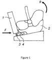
- Fig. 1 shows a child safety seat 2 placed on a seat of a vehicle, wherein the orientation of the child safety seat 2 is rear-facing, i.e. a child, when positioned in the child safety seat 2, faces the rear of the vehicle.
- the child safety seat 2 comprises ISOFIX connectors 4 engaged with, i.e. connected with, ISOFIX anchoring points 3 of the vehicle to secure the child safety seat 2 to the vehicle.
- an ISOFIX child safety seat 2 usually comprises a mechanism, such as a ratchet mechanism, which allows the ISOFIX connectors 4 to be ejected and to be retracted again.
- a mechanism such as a ratchet mechanism
- inertial forces directed towards the seatback 1 act on the child safety seat 2.
- the ratchet mechanism or a similar mechanism connected with the ISOFIX connectors 4 allows the ISOFIX connectors 4 to retract (i.e. move in the first direction in relation to the child safety seat 2), the child safety seat 2 will move towards the seatback 1 (i.e. be pressed into the cushion of the seatback 1), possibly until the ISOFIX connectors 4 are fully retracted.
- This movement is not impeded, only the cushion of the seatback 1 may decelerate the moving child safety seat 2 before the child safety seat 2 is abruptly stopped when the ISOFIX connectors 4 are fully retracted.
- the present invention makes use of the accelerating forces occurring during a car crash for decelerating the movement of the child safety seat 2 towards the seatback in a car crash involving a rear impact.
- the absorption of kinetic energy of the child safety seat 2 reduces accelerating forces acting on a child positioned in the child safety seat 2 and impedes rotary motions of the child safety seat 2. Thus, risk of injury for the child can be reduced.
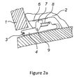
- Figs. 2a and 2b show an apparatus for a child safety seat 2 in accordance with an embodiment of the invention.
- the apparatus comprises a releasable connector 4 configured to be coupled to an anchoring point 3 provided in a vehicle to secure the child safety seat 2 to the vehicle.
- the apparatus further comprises a component (not shown in Figs. 2a and 2b ) configured to allow movement of the releasable connector 4 in a first direction and prevent movement of the releasable connector 4 in a second direction opposite to the first direction.
- the component configured to allow movement of the releasable connector 4 in the first direction and prevent movement of the releasable connector 4 in the second direction opposite to the first direction preferably comprises a ratchet mechanism.
- the apparatus further comprises a braking element 7 pivotally coupled to the releasable connector 4 and an elastic element 8, in particular a spring or coil spring.
- the apparatus preferably comprises a plate element 6 configured to be attached to a base or lower portion of the child safety seat 2.
- the braking element 7 is rotatably supported by a swivel 9 provided on the releasable connector 4 such that the swivel 9, which is the center of rotation, is spaced apart from the center of gravity of the braking element 7.
- inertial forces will cause the braking element 7 to rotate if the releasable connector 4 is accelerated in the direction indicated by arrow A (see Fig 2b ).
- the braking element 7 comes into contact with the plate element 6 (or a surface of the child safety seat 2 if no plate element is provided)
- movement of the releasable connector 4 will be decelerated.
- the braking element 7 In the initial position of the braking element 7, when the releasable connector 4 is not accelerated, the braking element 7 is not in contact with the plate element 6 and does not impede movements of the releasable connector 4 (see Fig 2a ).
- the braking element 7 preferably has a pivot bearing at one side and a rounded surface on the opposite side, wherein the pivot or swivel 9 provided on the releasable connector 4 is configured to be inserted into the pivot bearing of the braking element 7.
- the braking element 7 preferably has a tapered form, wherein its width tapers from the side having the rounded surface towards the side having the pivot bearing.
- the rounded surface of braking element 7 is configured to come into contact with the plate element 6 (or a surface of the child safety seat 2 if no plate element is provided) and generate friction, wherein the curvature of the braking element is formed depending on the desired amount of friction and/or grip.
- the braking element 7 may decelerate the movement of the releasable connector 4 by providing a friction force caused by friction between the braking element 7 and the plate element 6 (or the surface of the child safety seat 2). More precisely, if the accelerating force acting on the releasable connector 4 in the first direction exceeds a predetermined threshold (defined, amongst others, by the flexibility of the elastic element 8), the braking element 7 rotates and comes into contact with the surface of the plate element 6 such that the contacting surfaces of the braking element 7 and the plate element 6 cause friction decelerating the movement of the releasable connector 4.
- a predetermined threshold defined, amongst others, by the flexibility of the elastic element 8
- the braking element 7 may rotate and come into contact with the surface of the plate element 6 such that the braking element 7 and the plate element 6 become wedged together if the accelerating force acting on the releasable connector 4 in the first direction exceeds a predetermined threshold. Kinetic energy may then be absorbed by deforming the plate element 6, a part of child safety seat 2 adjacent to the plate element 6 and/or the braking element 7.
- the spring 8 forms an additional connection between the braking element 7 and the releasable connector 4 to inhibit or decelerate rotations caused by an acceleration force acting on the releasable connector 4 in the first direction. More precisely, the spring 8 reduces rotation of the braking element 7 such that the braking element 7 does not decelerate the movement of the releasable connector 4 if the rotational forces caused by inertial forces due to acceleration of the releasable connector 4 do not exceed a predetermined threshold which can be set by selecting a spring 8 having a suitable spring stiffness. Thus, the spring 8 provides a retention force for holding the braking element 7 at its initial position and/or returning the braking element 7 to its initial position. Only after the rotational forces caused by the acceleration of the releasable connector 4 have exceeded a predetermined threshold, the braking element may rotate far enough to touch the plate element 6.
- the spring 8 ensures that the braking element 7 does not hinder the installation of the child safety seat 2 in the vehicle.
- the spring 8 prevents the braking element 7 from impeding or even blocking movement of the releasable connector 4 when the releasable connector 4 is extended and needs to be retracted in order to install the child safety seat 2 in a vehicle.
- the spring 8 will not prevent the braking element 7 from decelerating the movement of the releasable connector 4 if large accelerating forces caused by a car crash act on the child safety seat 2 in which the releasable connector 4 and the braking element 7 are installed.
- Fig. 3 shows a further embodiment of an apparatus in accordance with the present invention which is similar to the embodiment shown in Figs. 2a and 2b .
- at least parts of the surfaces of the braking element 7 and the plate element 6 are serrated.
- Fig. 3 shows an embodiment wherein at least parts of the surfaces of both the braking element 7 and the plate element 6 are serrated, it is also possible that only the braking element 7 is provided with an at least partly serrated surface and the plate element 6 has a smooth or a rough, but not serrated surface.
- the friction between the braking element 7 and the plate element 6 is increased by providing the braking element 7 and the plate element 6 with an at least partly serrated surface.
- friction between the braking element 7 and the plate element 6 is increased as the teeth of the braking element 7 and the teeth the plate element 6 will interlock when the braking element 7 touches the plate element 6.
- the teeth depth of the serration of the braking element 7 is preferably between 1,0 mm and 3,0 mm, more preferably between 1,5 mm and 2,0 mm.
- the teeth depth of the serration of the plate element 6 is preferably equal to or smaller than the teeth depth of the serration of the braking element 7.
- the plate element 6 comprises or consists of plastic and the braking element 7 comprises or consists of metal, preferably steel.
- This combination of materials further increases the absorption of kinetic energy, as the metal teeth of the braking element 7 grate, scratch and/or deform the plastic teeth of the plate element 6 or the plate element 6 as a whole.
- both the braking element 7 and the plate element 6 comprise or consist of plastic, preferably the braking element 7 comprises or consists of duroplastic plastics and the plate element 6 comprises or consists of plastic which is softer than the duroplastic plastics used for the braking element 7.
- Fig. 4 shows a further embodiment of the present invention which is similar to the embodiment shown in Figs. 2a and 2b .
- the materials of the braking element 7 and the plate element 6 are selected such that the coefficient of friction of the materials of the braking element 7 and the plate element 6 is sufficiently large for the braking element 7 and the plate element 6 to become wedged together if the accelerating force acting on the releasable connector 4 in the first direction exceeds a predetermined threshold.
- the braking element 7 and/or the plate element 6 comprises or consists of rubber.
- the surfaces of the braking element 7 and/or the plate element 6 may be rough or even serrated in order to increase the friction between of the braking element 7 and the plate element 6.
- additional kinetic energy is absorbed by converting the kinetic energy into deformation energy of one or more parts of the child safety seat 2 including the apparatus according to the invention.
- the plate element 6, the releasable connector 4, the ratchet mechanism, and/or a lower part or base of the child safety seat which is adjacent to the plate element 6 may be deformed (symbolized by the arrow C in Fig.4 ).
- the material of the lower part or base of the child safety seat 2 adjacent to the plate element 6 is adapted to absorb kinetic energy by plastic deformation.
- a rubber element may be inserted in the lower part or base of the child safety seat 2.
Landscapes
- Engineering & Computer Science (AREA)
- Health & Medical Sciences (AREA)
- Child & Adolescent Psychology (AREA)
- General Health & Medical Sciences (AREA)
- Aviation & Aerospace Engineering (AREA)
- Transportation (AREA)
- Mechanical Engineering (AREA)
- Seats For Vehicles (AREA)
Abstract
Description
- The present invention relates to child safety seats for use in a vehicle and, more particularly, to an apparatus for a child safety seat, the apparatus being designed to increase the level of protection provided to a child seated in the child safety seat. In particular, the apparatus for a child safety seat is designed to prevent a child seat from being rotated and lifted during a rear impact on the vehicle carrying the child safety seat.
- Child safety seats are employed for safely transporting children in vehicles, in particular in cars. There is a large variety of child safety seats adapted for transporting children of different age ranges. In Europe, a system of groups has been established for categorizing child safety seats. This system ranges from "Group 0" seats suitable for newborn children via "
Group 1" and "Group 2" seats up to "Group 3" seats suitable for children up to twelve years old. Besides the age of a child, other factors that have to be taken into account when choosing a child safety seat for a specific child include the weight and the height of the child. - In principle, a child safety seat can be mounted in a vehicle in one of two orientations: forward-facing, i.e. in such a way that a child positioned in the child safety seat faces the front of the vehicle carrying the child safety seat; or rear-facing, i.e. in such a way that a child positioned in the child safety seat faces the rear of the vehicle carrying the child safety seat. The present invention relates in particular to apparatuses for child safety seats configured for rear-facing installation in the vehicle. The present invention, however, is not limited to rear-facing child safety seats, it might as well be applied to forward-facing child safety seats.
- The forces acting on a child sitting in a child safety seat during a crash of the vehicle carrying the child safety seat are influenced by the way the child safety seat is attached to the vehicle, i.e. by how the child safety seat is fixed to the vehicle seat it is placed on. Generally, there a two systems for fixing a child safety seat on a vehicle seat. The first system employs a seat belt provided in the vehicle for securing the child safety seat. In this system, at least one of the seat belts of the vehicle is guided in a prescribed way around or through the child safety seat thus securing the child safety seat in the desired position and orientation. An advantage of this system is that it exclusively makes use of fastening means that are usually present in every vehicle, i.e. the seat belts of the vehicle. Securing a child safety seat with a vehicle seat belt may, however, be cumbersome. Therefore, in practice, many child safety seats of this type are improperly installed in the vehicle. The second system employs fixing means which are provided in the vehicle specifically for securing a child safety seat. In Europe, the ISOFIX system has been introduced for this purpose. A vehicle seat adapted for installation of an ISOFIX child safety seat (i.e. a child safety seat equipped with the ISOFIX system) comprises anchors (ISOFIX anchors) which are provided at the lower end of the seat's seatback at the junction between the seat cushion and the seatback and which are fixedly attached to the seat. The ISOFIX child safety seat comprises connectors or latches (ISOFIX rigid latches) which can be coupled releasably to the anchors. Consequently, using the ISOFIX system a child safety seat can be easily and safely fixed to a vehicle seat. The child safety seat may furthermore comprise a Top Tether, a support leg, or a Rebound Bar, as an anti-rotation device.
- The present invention relates in particular to apparatuses for ISOFIX child safety seats. The present invention, however, is not limited to ISOFIX child safety seats, it might as well be applied to other child safety seats having similar means for fixing the child safety seat to a vehicle seat.
- In the following, illustrations and descriptions refer to rear-facing ISOFIX child safety seats, which is for reasons of simplicity only and does not limit the invention to apparatuses for rear-facing ISOFIX child safety seats only.
- In a car crash involving a rear collision of the vehicle, a child safety seat is pushed towards the seatback of a seat of the vehicle. Due to that, rotary forces will act on the child safety seat, as the center of gravity of the child safety seat is located above the ISOFIX connectors attached to the ISOFIX anchoring points. Thus, the child safety seat will be rotated upwards, resulting in an increased risk of injury for the child in the child safety seat. Further, accelerating forces induced by the rear impact are directly transferred to the child safety seat and, thus, also to the child in the child safety seat.
- As already mentioned above, a Rebound Bar may be used to inhibit such a rotation of the child safety seat. However, a Rebound Bar makes a child safety seat heavier and more unhandy, which is particularly disadvantageous when carrying a baby lying in the child safety seat to a vehicle.
- Therefore, it is an object of the present invention to provide an apparatus for a child safety seat which reduces the risk of injury for a child in the child safety seat during a rear collision of the vehicle and does not require additional effort and/or action of the user.
- This and other objects are achieved by the apparatus for a child safety seat according to
claim 1. Advantageous embodiments of the present invention are indicated insubclaims 2 to 15. - According to an aspect of the invention, there is provided an apparatus for a child safety seat, the apparatus comprising a releasable connector configured to engage with an anchoring point provided in a vehicle to secure the child safety seat to the vehicle, wherein the releasable connector is movable in a first direction relative to the child safety seat; and the apparatus further comprises a braking element coupled to the releasable connector and configured to decelerate a movement of the releasable connector in the first direction if an accelerating force acting on the releasable connector in the first direction exceeds a predetermined threshold.
- By decelerating the movement of the releasable connector in the first direction as described above, the braking element in accordance with the invention will slow down, impede or even block movement of the releasable connector relative to the child safety seat in the first direction. In accordance with the invention, the braking element may be directly or indirectly coupled to the releasable connector. In particular, in accordance with the invention the braking element may be mounted on a component rigidly coupled to the releasable connector. Preferably, the braking element is movably mounted on said component.
- Advantageously, the braking element is pivotally coupled to the releasable connector and configured to rotate about a rotation axis which is spaced apart from the center of gravity of the braking element such that a rotary force acts on the braking element if the releasable connector is accelerated. As the braking element is not supported at its center of gravity but at a point spaced apart from its center of gravity, a rotary force acts on the braking element due to inertial forces acting on the braking element if the releasable connector is accelerated.
- Advantageously, the braking element is additionally connected to the releasable connector by an elastic element such that an elastic force caused by the elastic element acts against the rotary force caused by the acceleration of the releasable connector in the first direction, wherein the elastic element preferably is a spring or coil spring. Therefore, the elastic element provides a retention force to hold the braking element at its initial position and/or return the braking element to its initial position.
- The elastic element reduces rotation of the braking element such that the braking element does not decelerate the movement of the releasable connector if the rotational forces caused by inertial forces due to acceleration of the releasable connector do not exceed a predetermined threshold which can be set by selecting a suitable elastic element. Thus, the elastic element ensures that the braking element does not hinder the installation of the child safety seat in the vehicle. In particular, the elastic element prevents the braking element from impeding or even blocking movement of the releasable connector when the releasable connector is being retracted to install the child safety seat in a vehicle. At the same time, the elastic element will not prevent the braking element from decelerating the movement of the releasable connector if large accelerating forces caused by a car crash act on the child safety seat in which the releasable connector and the braking element are installed.
- Advantageously, the apparatus further comprises a component configured to allow movement of the releasable connector in the first direction and prevent movement of the releasable connector in a second direction opposite to the first direction.
- Preferably, the component configured to allow movement of the releasable connector in the first direction and prevent movement of the releasable connector in the second direction opposite to the first direction comprises a ratchet mechanism.
- Advantageously, the releasable connector comprises an ISOFIX connector of a child safety seat.
- An ISOFIX child safety seat, i.e. a child safety seat configured to be secured to a vehicle by means of the ISOFIX system, comprises ISOFIX connectors or latches (ISOFIX rigid latches) which can releasably be coupled to ISOFIX anchoring points or anchors of a vehicle equipped with the ISOFIX system. The ISOFIX anchoring points are provided at the lower end of the seat's seatback at the junction between the seat cushion and the seatback and are fixedly attached to the seat in the vehicle equipped with the ISOFIX system. The ISOFIX connectors or ISOFIX rigid latches are commonly connected to the child safety seat with a ratchet mechanism or a comparable mechanism in order to adjust the ISOFIX connectors to different seat designs and sizes used in different vehicle types and to allow easy installation of the child safety seat in the vehicle: First, the locking mechanism of the ratchet mechanism can manually be released and the ISOFIX connectors may be fully extended to ease connecting the ISOFIX connectors to the ISOFIX anchoring points. Then, the child safety seat may be moved towards the seatback of the car seat to come in tight contact with the seatback of the car seat. The ratchet mechanism secures the child safety seat as it only allows movement of the ISOFIX connectors in a first direction (i.e. the ISOFIX connectors are allowed to be retracted and, thus, the child safety seat can easily be moved towards the seatback of the car seat) and prevents movement of the ISOFIX connectors in a second direction opposite to the first direction (i.e. the ISOFIX connectors are prevented from extending and, thus, the child safety seat is prevented from moving away from the seatback of the car seat).
- Advantageously, the braking element is configured to decelerate the movement of the releasable connector by providing a friction force caused by friction between the braking element and a surface of the child safety seat. More precisely, if the accelerating force acting on the releasable connector in the first direction exceeds a predetermined threshold, the braking element rotates and comes into contact with the surface of the child safety seat such that the contacting surfaces of the braking element and the child safety seat cause friction decelerating the movement of the releasable connector.
- Additionally or alternatively, the braking element may rotate and come into contact with the surface of the child safety seat such that the braking element and the surface of the child safety seat become wedged together if the accelerating force acting on the releasable connector in the first direction exceeds a predetermined threshold. Kinetic energy is then additionally absorbed by deforming the surface of the child safety seat and/or the braking element.
- According to an embodiment of the invention, the apparatus may further comprise a plate element configured to be mounted on a surface of the child safety seat such that the plate element comes into contact with the braking element if the accelerating force acting on the releasable connector in the first direction exceeds the predetermined threshold.
- Advantageously, the braking element is configured to decelerate the movement of the releasable connector by providing a friction force caused by friction between the braking element and the plate element.
- According to a further embodiment of the invention, at least a part of the surface of the braking element is serrated, wherein the teeth depth of the serration of the braking element is preferably between 1,0 mm and 3,0 mm, more preferably between 1,5 mm and 2,0 mm.
- In this embodiment of the invention, the friction between the braking element and the plate element is increased by providing the braking element with a serrated surface.
- Advantageously, the plate element comprises or consists of plastic and the braking element comprises or consists of metal, preferably steel. This combination of materials enables a higher absorption of kinetic energy, as the metal teeth of the braking element scratch and deform the plastic plate element. It is, however, also possible that both the braking element and the plate element comprise or consist of plastic, preferably the braking element comprises or consists of duroplastic plastics and the plate element comprises or consists of plastic which is softer than the duroplastic plastics used for the braking element.
- Advantageously, at least a part of the surface of the plate element is serrated which further increases the friction between the braking element and the plate element.
- In a further embodiment of the invention, at least parts of the surfaces of both the braking element and the plate element are serrated which additionally increases the friction between the braking element and the plate element as the teeth of the braking element and the plate element will interlock when the braking element touches the plate element.
- Advantageously, the plate element comprises or consists of plastic and the braking element comprises or consists of metal.
- In this embodiment, kinetic energy is additionally absorbed by the metal teeth of the braking element grating the plastic teeth of the plate element. The teeth depth of the serrations of the braking element and the plate element may be suitably chosen depending on the desired friction force, wherein the teeth depth of the braking element is preferably equal to or larger than the teeth depth of the plate element.
- Advantageously, the materials of the braking element and the plate element are selected such that the coefficient of friction of the material of the braking element and the plate element is sufficiently large for the braking element and the plate element to become wedged together if the accelerating force acting on the releasable connector in the first direction exceeds a predetermined threshold. Preferably, the braking element and/or the plate element comprises or consists of rubber. Alternatively or additionally, the surfaces of the braking element and/or the plate element may be rough or even serrated in order to increase the friction between of the braking element and the plate element.
- According to a further aspect of the invention, there is provided a child safety seat comprising the apparatus specified above.
- Advantageously, the child safety seat is an ISOFIX child safety seat.
- Preferably, the child safety seat is configured for a rear-facing installation in the vehicle.
- Specific embodiments of the invention will now be described by way of example and with reference to the accompanying drawings, in which:
-
Figure 1 is a side view of a child safety seat in which the apparatus according to the invention may be employed; -
Figure 2a shows an embodiment of an apparatus in accordance with the invention, wherein the braking element is in an initial position; -
Figure 2b shows the apparatus ofFigure 2a with the braking element being in a displaced position; -
Figure 3 shows a further embodiment of an apparatus in accordance with the invention; -
Figure 4 shows a further embodiment of an apparatus in accordance with the invention. -
Fig. 1 shows achild safety seat 2 placed on a seat of a vehicle, wherein the orientation of thechild safety seat 2 is rear-facing, i.e. a child, when positioned in thechild safety seat 2, faces the rear of the vehicle. Thechild safety seat 2 comprisesISOFIX connectors 4 engaged with, i.e. connected with,ISOFIX anchoring points 3 of the vehicle to secure thechild safety seat 2 to the vehicle. - In a car crash involving a rear collision of the vehicle (resulting in a force acting on the vehicle in the direction of arrow F), the
child safety seat 2 is pushed towards theseatback 1 of the seat of the vehicle. Due to that, rotary forces will act on thechild safety seat 2, as the center of gravity of thechild safety seat 2 is located above theISOFIX connectors 4 attached to the ISOFIX anchoring points 3. Thus, thechild safety seat 2 will be rotated upwards (see arrow R inFig. 1 ) resulting in an increased risk of injury for the child in thechild safety seat 2. Further, accelerating forces induced by the rear impact are directly transferred to thechild safety seat 2 and, thus, also to the child in thechild safety seat 2. - As described above, in ISOFIX
child safety seats 2 theISOFIX connectors 4 can usually be shifted or displaced relative to thechild safety seat 2 in order to facilitate the installation of thechild safety seat 2 and to adapt to different geometries of vehicle seats. Thus, an ISOFIXchild safety seat 2 usually comprises a mechanism, such as a ratchet mechanism, which allows theISOFIX connectors 4 to be ejected and to be retracted again. When an ISOFIXchild safety seat 2 is properly installed in a vehicle, usually theISOFIX connectors 4 are not fully retracted. - In a car crash involving a rear collision of the vehicle, inertial forces directed towards the
seatback 1 act on thechild safety seat 2. As the ratchet mechanism or a similar mechanism connected with theISOFIX connectors 4 allows theISOFIX connectors 4 to retract (i.e. move in the first direction in relation to the child safety seat 2), thechild safety seat 2 will move towards the seatback 1 (i.e. be pressed into the cushion of the seatback 1), possibly until theISOFIX connectors 4 are fully retracted. This movement is not impeded, only the cushion of theseatback 1 may decelerate the movingchild safety seat 2 before thechild safety seat 2 is abruptly stopped when theISOFIX connectors 4 are fully retracted. - The present invention makes use of the accelerating forces occurring during a car crash for decelerating the movement of the
child safety seat 2 towards the seatback in a car crash involving a rear impact. The absorption of kinetic energy of thechild safety seat 2 reduces accelerating forces acting on a child positioned in thechild safety seat 2 and impedes rotary motions of thechild safety seat 2. Thus, risk of injury for the child can be reduced. -
Figs. 2a and2b show an apparatus for achild safety seat 2 in accordance with an embodiment of the invention. The apparatus comprises areleasable connector 4 configured to be coupled to ananchoring point 3 provided in a vehicle to secure thechild safety seat 2 to the vehicle. The apparatus further comprises a component (not shown inFigs. 2a and2b ) configured to allow movement of thereleasable connector 4 in a first direction and prevent movement of thereleasable connector 4 in a second direction opposite to the first direction. The component configured to allow movement of thereleasable connector 4 in the first direction and prevent movement of thereleasable connector 4 in the second direction opposite to the first direction preferably comprises a ratchet mechanism. The apparatus further comprises abraking element 7 pivotally coupled to thereleasable connector 4 and anelastic element 8, in particular a spring or coil spring. The apparatus preferably comprises aplate element 6 configured to be attached to a base or lower portion of thechild safety seat 2. - The
braking element 7 is rotatably supported by aswivel 9 provided on thereleasable connector 4 such that theswivel 9, which is the center of rotation, is spaced apart from the center of gravity of thebraking element 7. Thus, inertial forces will cause thebraking element 7 to rotate if thereleasable connector 4 is accelerated in the direction indicated by arrow A (seeFig 2b ). When thebraking element 7 comes into contact with the plate element 6 (or a surface of thechild safety seat 2 if no plate element is provided), movement of thereleasable connector 4 will be decelerated. In the initial position of thebraking element 7, when thereleasable connector 4 is not accelerated, thebraking element 7 is not in contact with theplate element 6 and does not impede movements of the releasable connector 4 (seeFig 2a ). - The
braking element 7 preferably has a pivot bearing at one side and a rounded surface on the opposite side, wherein the pivot orswivel 9 provided on thereleasable connector 4 is configured to be inserted into the pivot bearing of thebraking element 7. Thebraking element 7 preferably has a tapered form, wherein its width tapers from the side having the rounded surface towards the side having the pivot bearing. The rounded surface ofbraking element 7 is configured to come into contact with the plate element 6 (or a surface of thechild safety seat 2 if no plate element is provided) and generate friction, wherein the curvature of the braking element is formed depending on the desired amount of friction and/or grip. - The
braking element 7 may decelerate the movement of thereleasable connector 4 by providing a friction force caused by friction between thebraking element 7 and the plate element 6 (or the surface of the child safety seat 2). More precisely, if the accelerating force acting on thereleasable connector 4 in the first direction exceeds a predetermined threshold (defined, amongst others, by the flexibility of the elastic element 8), thebraking element 7 rotates and comes into contact with the surface of theplate element 6 such that the contacting surfaces of thebraking element 7 and theplate element 6 cause friction decelerating the movement of thereleasable connector 4. - Alternatively or additionally, the
braking element 7 may rotate and come into contact with the surface of theplate element 6 such that thebraking element 7 and theplate element 6 become wedged together if the accelerating force acting on thereleasable connector 4 in the first direction exceeds a predetermined threshold. Kinetic energy may then be absorbed by deforming theplate element 6, a part ofchild safety seat 2 adjacent to theplate element 6 and/or thebraking element 7. - The
spring 8 forms an additional connection between thebraking element 7 and thereleasable connector 4 to inhibit or decelerate rotations caused by an acceleration force acting on thereleasable connector 4 in the first direction. More precisely, thespring 8 reduces rotation of thebraking element 7 such that thebraking element 7 does not decelerate the movement of thereleasable connector 4 if the rotational forces caused by inertial forces due to acceleration of thereleasable connector 4 do not exceed a predetermined threshold which can be set by selecting aspring 8 having a suitable spring stiffness. Thus, thespring 8 provides a retention force for holding thebraking element 7 at its initial position and/or returning thebraking element 7 to its initial position. Only after the rotational forces caused by the acceleration of thereleasable connector 4 have exceeded a predetermined threshold, the braking element may rotate far enough to touch theplate element 6. - Accordingly, the
spring 8 ensures that thebraking element 7 does not hinder the installation of thechild safety seat 2 in the vehicle. In particular, thespring 8 prevents thebraking element 7 from impeding or even blocking movement of thereleasable connector 4 when thereleasable connector 4 is extended and needs to be retracted in order to install thechild safety seat 2 in a vehicle. At the same time, thespring 8 will not prevent thebraking element 7 from decelerating the movement of thereleasable connector 4 if large accelerating forces caused by a car crash act on thechild safety seat 2 in which thereleasable connector 4 and thebraking element 7 are installed. -
Fig. 3 shows a further embodiment of an apparatus in accordance with the present invention which is similar to the embodiment shown inFigs. 2a and2b . However, in the embodiment shown inFig. 3 , at least parts of the surfaces of thebraking element 7 and theplate element 6 are serrated. ThoughFig. 3 shows an embodiment wherein at least parts of the surfaces of both thebraking element 7 and theplate element 6 are serrated, it is also possible that only thebraking element 7 is provided with an at least partly serrated surface and theplate element 6 has a smooth or a rough, but not serrated surface. - In the embodiment shown in
Figure 3 , the friction between thebraking element 7 and theplate element 6 is increased by providing thebraking element 7 and theplate element 6 with an at least partly serrated surface. In this embodiment, friction between thebraking element 7 and theplate element 6 is increased as the teeth of thebraking element 7 and the teeth theplate element 6 will interlock when thebraking element 7 touches theplate element 6. The teeth depth of the serration of thebraking element 7 is preferably between 1,0 mm and 3,0 mm, more preferably between 1,5 mm and 2,0 mm. The teeth depth of the serration of theplate element 6 is preferably equal to or smaller than the teeth depth of the serration of thebraking element 7. - Advantageously, the
plate element 6 comprises or consists of plastic and thebraking element 7 comprises or consists of metal, preferably steel. This combination of materials further increases the absorption of kinetic energy, as the metal teeth of thebraking element 7 grate, scratch and/or deform the plastic teeth of theplate element 6 or theplate element 6 as a whole. It is, however, also possible that both thebraking element 7 and theplate element 6 comprise or consist of plastic, preferably thebraking element 7 comprises or consists of duroplastic plastics and theplate element 6 comprises or consists of plastic which is softer than the duroplastic plastics used for thebraking element 7. -
Fig. 4 shows a further embodiment of the present invention which is similar to the embodiment shown inFigs. 2a and2b . In this embodiment, the materials of thebraking element 7 and theplate element 6 are selected such that the coefficient of friction of the materials of thebraking element 7 and theplate element 6 is sufficiently large for thebraking element 7 and theplate element 6 to become wedged together if the accelerating force acting on thereleasable connector 4 in the first direction exceeds a predetermined threshold. Preferably, thebraking element 7 and/or theplate element 6 comprises or consists of rubber. Alternatively or additionally, the surfaces of thebraking element 7 and/or theplate element 6 may be rough or even serrated in order to increase the friction between of thebraking element 7 and theplate element 6. - In this embodiment, additional kinetic energy is absorbed by converting the kinetic energy into deformation energy of one or more parts of the
child safety seat 2 including the apparatus according to the invention. Accordingly, theplate element 6, thereleasable connector 4, the ratchet mechanism, and/or a lower part or base of the child safety seat which is adjacent to theplate element 6 may be deformed (symbolized by the arrow C inFig.4 ). Preferably, the material of the lower part or base of thechild safety seat 2 adjacent to theplate element 6 is adapted to absorb kinetic energy by plastic deformation. For example, a rubber element may be inserted in the lower part or base of thechild safety seat 2.
Claims (15)
- An apparatus for a child safety seat (2), the apparatus comprising a releasable connector (4) configured to engage with an anchoring point (3) provided in a vehicle to secure the child safety seat (2) to the vehicle, wherein
the releasable connector (4) is movable relative to the child safety seat (2) in a first direction; and
the apparatus further comprises a braking element (7) coupled to the releasable connector (4) and configured to decelerate a movement of the releasable connector (4) in the first direction if an accelerating force acting on the releasable connector (4) in the first direction exceeds a predetermined threshold. - The apparatus of claim 1, wherein the braking element (7) is pivotally coupled to the releasable connector (4) and is configured to rotate about a rotation axis of the braking element (7) which is spaced apart from the center of gravity of the braking element (7) such that a rotary force acts on the braking element (7) if the releasable connector (4) is accelerated.
- The apparatus of claim 2, wherein the braking element (7) is additionally connected to the releasable connector (4) by an elastic element (8) such that an elastic force caused by the elastic element (8) acts against the rotary force caused by an acceleration of the releasable connector (4) in the first direction.
- The apparatus of claim 3, wherein the elastic element (8) is a spring.
- The apparatus of one of the preceding claims, wherein the apparatus further comprises a component configured to allow movement of the releasable connector (4) in the first direction and prevent movement of the releasable connector (4) in a second direction opposite to the first direction.
- The apparatus of claim 5, wherein the component configured to allow movement of the releasable connector (4) in the first direction and prevent movement of the releasable connector (4) in the second direction opposite to the first direction comprises a ratchet mechanism.
- The apparatus of one of the preceding claims, wherein the releasable connector (4) comprises an ISOFIX connector of a child safety seat (2).
- The apparatus of one of the preceding claims, wherein the braking element (7) is configured to decelerate the movement of the releasable connector (4) by providing a friction force caused by friction between the braking element (7) and a surface of the child safety seat (2).
- The apparatus of one of the preceding claims, further comprising a plate element (6) configured to be mounted on a surface of the child safety seat (2) such that the plate element (6) comes into contact with the braking element (7) if the accelerating force acting on the releasable connector (4) in the first direction exceeds the predetermined threshold.
- The apparatus of claim 9, wherein at least a part of the surface of the braking element (7) is serrated.
- The apparatus of claim 9 or 10, wherein at least a part of the surface of the plate element (6) is serrated.
- The apparatus of one of claims 9 - 11, wherein the plate element (6) comprises or consists of plastic and the braking element (7) comprises or consists of metal.
- The apparatus of claim 9, wherein the materials of the braking element (7) and the plate element (6) are selected such that the coefficient of friction of the material of the braking element (7) and the plate element (6) is sufficiently large for the braking element (7) and the plate element (6) to become wedged together if the accelerating force acting on the releasable connector (4) in the first direction exceeds a predetermined threshold.
- A child safety seat (2) comprising the apparatus of one of the preceding claims.
- The child safety seat (2) of claim 14, wherein the child safety seat (2) is configured for a rear-facing installation in the vehicle.
Priority Applications (7)
| Application Number | Priority Date | Filing Date | Title |
|---|---|---|---|
| EP16002094.7A EP3300946B1 (en) | 2016-09-28 | 2016-09-28 | Apparatus for use in a child safety seat |
| ES16002094T ES2886574T3 (en) | 2016-09-28 | 2016-09-28 | Apparatus for use in a child safety seat |
| CA2978806A CA2978806C (en) | 2016-09-28 | 2017-09-08 | Apparatus for use in a child safety seat |
| CN201710851212.4A CN107867207B (en) | 2016-09-28 | 2017-09-20 | Device for a child safety seat |
| AU2017232122A AU2017232122B2 (en) | 2016-09-28 | 2017-09-21 | Apparatus for use in a child safety seat |
| RU2017133635A RU2687398C2 (en) | 2016-09-28 | 2017-09-27 | Device for use in a child safety seat |
| US15/718,187 US10589644B2 (en) | 2016-09-28 | 2017-09-28 | Apparatus for use in a child safety seat |
Applications Claiming Priority (1)
| Application Number | Priority Date | Filing Date | Title |
|---|---|---|---|
| EP16002094.7A EP3300946B1 (en) | 2016-09-28 | 2016-09-28 | Apparatus for use in a child safety seat |
Publications (2)
| Publication Number | Publication Date |
|---|---|
| EP3300946A1 true EP3300946A1 (en) | 2018-04-04 |
| EP3300946B1 EP3300946B1 (en) | 2021-06-02 |
Family
ID=57042645
Family Applications (1)
| Application Number | Title | Priority Date | Filing Date |
|---|---|---|---|
| EP16002094.7A Active EP3300946B1 (en) | 2016-09-28 | 2016-09-28 | Apparatus for use in a child safety seat |
Country Status (7)
| Country | Link |
|---|---|
| US (1) | US10589644B2 (en) |
| EP (1) | EP3300946B1 (en) |
| CN (1) | CN107867207B (en) |
| AU (1) | AU2017232122B2 (en) |
| CA (1) | CA2978806C (en) |
| ES (1) | ES2886574T3 (en) |
| RU (1) | RU2687398C2 (en) |
Cited By (1)
| Publication number | Priority date | Publication date | Assignee | Title |
|---|---|---|---|---|
| US11981235B2 (en) | 2021-03-26 | 2024-05-14 | Wonderland Switzerland Ag | Child safety seat |
Families Citing this family (4)
| Publication number | Priority date | Publication date | Assignee | Title |
|---|---|---|---|---|
| US11618353B2 (en) | 2019-08-09 | 2023-04-04 | Wonderland Switzerland Ag | Methods, apparatus and systems for securing an infant car seat to a vehicle seat with a tight fit and without using a detachable vehicle installation base or a vehicle seat belt, and ride-hailing methods relating to same |
| TWI866848B (en) | 2019-08-09 | 2024-12-11 | 瑞士商明門瑞士股份有限公司 | Infant car seat system |
| US11673493B1 (en) | 2020-07-31 | 2023-06-13 | Steven J. Randall | Children's car seat adapter |
| TW202306805A (en) * | 2021-01-25 | 2023-02-16 | 瑞士商明門瑞士股份有限公司 | Infant car seat anchoring assembly with retractable foot |
Citations (2)
| Publication number | Priority date | Publication date | Assignee | Title |
|---|---|---|---|---|
| DE19952771A1 (en) * | 1998-11-05 | 2001-05-10 | Orth Michael | Child's active vehicle safety seat with an integrated shock absorber system to reduce the energy of heavy braking and thus injury to the child |
| US20160121764A1 (en) * | 2014-10-30 | 2016-05-05 | Diono, Llc | Rear facing ride down safety seat |
Family Cites Families (60)
| Publication number | Priority date | Publication date | Assignee | Title |
|---|---|---|---|---|
| US5286085A (en) * | 1989-06-30 | 1994-02-15 | Takata Corporation | Restraining protective seat for infants |
| EP0499665B1 (en) * | 1991-02-20 | 1994-07-27 | Trw Repa Gmbh | Pre-tensioning device in a seat-belt system for automotive vehicles |
| US5290089A (en) * | 1992-12-28 | 1994-03-01 | General Motors Corporation | Seat bellows energy absorber |
| GB9307446D0 (en) * | 1993-04-08 | 1993-06-02 | Britax Excelsior | Child safety seat |
| US5538322A (en) * | 1993-10-01 | 1996-07-23 | Cosco, Inc. | Child car seat with adjustable barrier shield |
| AU716487B2 (en) * | 1995-09-14 | 2000-02-24 | Autoliv Development Ab | A seat for use in a vehicle |
| US5810417A (en) * | 1995-09-28 | 1998-09-22 | Mongkol Jesadanont | Automatic safety car seats and sheet-type safety-belt |
| US5690356A (en) * | 1995-11-30 | 1997-11-25 | Alliedsignal Inc. | Integrated switch for air bag deactivation |
| US5685603A (en) * | 1996-03-05 | 1997-11-11 | Trw Vehicle Safety Systems Inc. | Apparatus with a child seat and an energy absorption mechanism |
| US5884967A (en) * | 1997-04-17 | 1999-03-23 | Gasper; Ronald | Child vehicle safety seat |
| US6017087A (en) * | 1998-08-18 | 2000-01-25 | Indiana Mills And Manufacturing, Inc. | Child restraint with a rotary coupling |
| JP2000210294A (en) * | 1998-11-20 | 2000-08-02 | Asahi Optical Co Ltd | Endoscope biopsy forceps |
| US6209957B1 (en) * | 1999-06-10 | 2001-04-03 | Britax Child Safety Inc. | Child safety seat |
| JP2001097086A (en) * | 1999-09-28 | 2001-04-10 | Combi Corp | child seat |
| US6799799B2 (en) * | 1999-10-09 | 2004-10-05 | Britax Romer Kindersicherheit Gmbh | Child safety seat |
| JP2001206117A (en) * | 2000-01-27 | 2001-07-31 | Honda Motor Co Ltd | Attachment for infant seat |
| US6302481B1 (en) * | 2000-02-04 | 2001-10-16 | Trw Inc. | Thrust and rock vehicle seat |
| JP3434494B2 (en) * | 2000-09-06 | 2003-08-11 | 本田技研工業株式会社 | Adult seat lock mechanism that can be flipped up |
| JP2002178811A (en) * | 2000-12-14 | 2002-06-26 | Takata Corp | Child seat device |
| US6921133B2 (en) * | 2001-02-21 | 2005-07-26 | Daihatsu Motor Co., Ltd. | Seat for car |
| JP4902070B2 (en) * | 2001-08-22 | 2012-03-21 | コンビ株式会社 | child seat |
| US6767057B2 (en) * | 2002-09-17 | 2004-07-27 | General Motors Corporation | Vehicle anchorage system for child seat |
| WO2005073017A1 (en) * | 2004-02-02 | 2005-08-11 | Daihatsu Motor Co., Ltd. | Automobile seat |
| US7207619B2 (en) * | 2004-03-26 | 2007-04-24 | Nissan Technical Center North America, Inc. | Child seat tether anchor structure |
| GB2412577B (en) * | 2004-03-31 | 2008-02-20 | Catalyst Developments | Fitting for child safety seat |
| GB2424921B (en) * | 2005-04-09 | 2010-03-03 | Jonathan Morris Gold | Fitting for child safety seat |
| FR2889826B1 (en) * | 2005-08-17 | 2008-10-17 | Equipbaby Uk Ltd | SAFETY SEAT FOR INSTALLING A BABY OR VERY YOUNG CHILD ON A VEHICLE SEAT. |
| US7338120B2 (en) * | 2006-05-12 | 2008-03-04 | Sabelt S.P.A. | Device for attaching a child safety seat to a fixed catch on a vehicle |
| US7611197B2 (en) * | 2006-06-26 | 2009-11-03 | International Truck Intellectual Property Company, Llc | Occupant restraint passenger seat assembly with load-sensing energy absorption feature |
| US8646158B2 (en) * | 2008-03-31 | 2014-02-11 | Amsafe Commercial Products, Inc. | Multi-pivot latch assemblies |
| US8291555B2 (en) * | 2008-03-31 | 2012-10-23 | Amsafe Commercial Products, Inc. | Multi-pivot latch assemblies |
| EP2308716A4 (en) * | 2008-07-02 | 2013-06-26 | Combi Corp | CHILD SEAT |
| US8240761B2 (en) * | 2008-09-25 | 2012-08-14 | Skjp Holdings, Llc | Lower anchor coupling |
| US8371425B2 (en) * | 2008-10-30 | 2013-02-12 | Ford Global Technologies, Llc | Dynamic displacement energy management device |
| DE202009013376U1 (en) * | 2009-10-19 | 2010-03-18 | Curt Würstl Vermögensverwaltungs-Gmbh & Co. Kg | Car seat |
| CN201587342U (en) * | 2009-12-30 | 2010-09-22 | 好孩子儿童用品有限公司 | baby car seat |
| US8662582B2 (en) * | 2010-11-24 | 2014-03-04 | Ford Global Technologies, Llc | Latch anchor inertial lock and pretensioner |
| US9452695B2 (en) * | 2011-08-19 | 2016-09-27 | Baby Trend, Inc. | Child car seat and base |
| EP2760700B1 (en) * | 2011-09-27 | 2016-11-02 | Mobius Protection Systems Ltd. | Safety seat |
| US8840184B2 (en) * | 2011-10-06 | 2014-09-23 | Thorley Industries Llc | Child restraint system with automated installation |
| EP2594427B1 (en) * | 2011-11-17 | 2017-10-11 | Wonderland Nurserygoods Company Limited | Support base for a child safety seat |
| CN103241148B (en) * | 2012-02-06 | 2015-10-07 | 宝钜儿童用品香港股份有限公司 | Child Safety Seat Fixing Mechanism |
| CN103419687B (en) * | 2012-05-15 | 2016-01-27 | 明门香港股份有限公司 | Fixtures for child safety seats |
| WO2014000014A1 (en) * | 2012-06-29 | 2014-01-03 | Infa-Secure Pty Ltd | A base unit for a child restraint |
| WO2014089619A1 (en) * | 2012-12-11 | 2014-06-19 | Infa-Secure Pty Ltd | An anchorage device |
| CN203228666U (en) * | 2013-04-28 | 2013-10-09 | 好孩子儿童用品有限公司 | Vehicle seat fixing connector |
| NO337587B1 (en) * | 2013-09-19 | 2016-05-09 | Torgersen Hans & Soenn | Child Seats |
| EP2853441B1 (en) * | 2013-09-25 | 2015-12-30 | Tachi-S Co., Ltd. | Vehicle seat |
| JP6180268B2 (en) * | 2013-10-01 | 2017-08-16 | 株式会社タチエス | Vehicle seat |
| US10176697B2 (en) * | 2014-06-17 | 2019-01-08 | Mobius Protection Systems Ltd. | Impact handling and ultrasound alerting methods |
| DE102014111923B4 (en) * | 2014-08-20 | 2017-03-30 | Volkswagen Aktiengesellschaft | Armrest with crash protection |
| EP3023293B1 (en) * | 2014-11-20 | 2017-12-27 | Britax Römer Kindersicherheit GmbH | Child safety seat |
| US9376078B1 (en) * | 2015-01-20 | 2016-06-28 | Ford Global Technologies, Llc | Seat mechanism inertia locking system |
| FR3032400B1 (en) * | 2015-02-09 | 2018-01-05 | Dorel France Sa | CAR SEAT FOR FOLDING CHILD WITH TOP TETHER STRAP |
| JP6582574B2 (en) * | 2015-06-11 | 2019-10-02 | トヨタ紡織株式会社 | Vehicle seat |
| US10328894B2 (en) * | 2015-11-20 | 2019-06-25 | Indiana Mills & Manufacturing, Inc. | Switchable retractor |
| JP6684657B2 (en) * | 2016-06-06 | 2020-04-22 | 日本発條株式会社 | Vehicle seat |
| ES1164333Y (en) * | 2016-07-29 | 2016-12-05 | Jane Sa | STRUCTURE FOR CHILD CHAIRS |
| US10252640B2 (en) * | 2017-08-21 | 2019-04-09 | Joyson Safety Systems Acquisition Llc | Seatbelt and child seat anchor based occupancy detection system |
| ES2806278T3 (en) * | 2017-09-14 | 2021-02-17 | Britax Roemer Kindersicherheit Gmbh | Support leg for a child safety seat |
-
2016
- 2016-09-28 EP EP16002094.7A patent/EP3300946B1/en active Active
- 2016-09-28 ES ES16002094T patent/ES2886574T3/en active Active
-
2017
- 2017-09-08 CA CA2978806A patent/CA2978806C/en active Active
- 2017-09-20 CN CN201710851212.4A patent/CN107867207B/en active Active
- 2017-09-21 AU AU2017232122A patent/AU2017232122B2/en active Active
- 2017-09-27 RU RU2017133635A patent/RU2687398C2/en active
- 2017-09-28 US US15/718,187 patent/US10589644B2/en active Active
Patent Citations (2)
| Publication number | Priority date | Publication date | Assignee | Title |
|---|---|---|---|---|
| DE19952771A1 (en) * | 1998-11-05 | 2001-05-10 | Orth Michael | Child's active vehicle safety seat with an integrated shock absorber system to reduce the energy of heavy braking and thus injury to the child |
| US20160121764A1 (en) * | 2014-10-30 | 2016-05-05 | Diono, Llc | Rear facing ride down safety seat |
Cited By (2)
| Publication number | Priority date | Publication date | Assignee | Title |
|---|---|---|---|---|
| US11981235B2 (en) | 2021-03-26 | 2024-05-14 | Wonderland Switzerland Ag | Child safety seat |
| US12337733B2 (en) | 2021-03-26 | 2025-06-24 | Wonderland Switzerland Ag | Child safety seat |
Also Published As
| Publication number | Publication date |
|---|---|
| CA2978806A1 (en) | 2018-03-28 |
| RU2687398C2 (en) | 2019-05-13 |
| AU2017232122B2 (en) | 2023-06-01 |
| AU2017232122A1 (en) | 2018-04-12 |
| CN107867207A (en) | 2018-04-03 |
| ES2886574T3 (en) | 2021-12-20 |
| CN107867207B (en) | 2020-11-06 |
| US10589644B2 (en) | 2020-03-17 |
| US20180086236A1 (en) | 2018-03-29 |
| RU2017133635A (en) | 2019-03-27 |
| CA2978806C (en) | 2019-12-31 |
| RU2017133635A3 (en) | 2019-03-27 |
| EP3300946B1 (en) | 2021-06-02 |
Similar Documents
| Publication | Publication Date | Title |
|---|---|---|
| US10589644B2 (en) | Apparatus for use in a child safety seat | |
| EP2161160B1 (en) | Child restraint system - ISOFIX | |
| JP5420579B2 (en) | Safety child seat with energy absorber | |
| US8226162B2 (en) | Child safety seat | |
| EP1953035B1 (en) | Child seat | |
| EP2613965B1 (en) | Rotating child safety seat | |
| WO2016069646A1 (en) | Rear facing ride down safety seat | |
| AU2024266801A1 (en) | Child safety seat with belted pivot link | |
| GB2417416A (en) | Adaptive vehicle child restraint system | |
| KR101265172B1 (en) | impact relaxation seat back for vehicle | |
| EP2772389B1 (en) | Child safety seat | |
| AU2026202769A1 (en) | Child safety seat with belted pivot link |
Legal Events
| Date | Code | Title | Description |
|---|---|---|---|
| PUAI | Public reference made under article 153(3) epc to a published international application that has entered the european phase |
Free format text: ORIGINAL CODE: 0009012 |
|
| STAA | Information on the status of an ep patent application or granted ep patent |
Free format text: STATUS: REQUEST FOR EXAMINATION WAS MADE |
|
| 17P | Request for examination filed |
Effective date: 20161108 |
|
| AK | Designated contracting states |
Kind code of ref document: A1 Designated state(s): AL AT BE BG CH CY CZ DE DK EE ES FI FR GB GR HR HU IE IS IT LI LT LU LV MC MK MT NL NO PL PT RO RS SE SI SK SM TR |
|
| AX | Request for extension of the european patent |
Extension state: BA ME |
|
| RBV | Designated contracting states (corrected) |
Designated state(s): AL AT BE BG CH CY CZ DE DK EE ES FI FR GB GR HR HU IE IS IT LI LT LU LV MC MK MT NL NO PL PT RO RS SE SI SK SM TR |
|
| STAA | Information on the status of an ep patent application or granted ep patent |
Free format text: STATUS: EXAMINATION IS IN PROGRESS |
|
| 17Q | First examination report despatched |
Effective date: 20200603 |
|
| GRAP | Despatch of communication of intention to grant a patent |
Free format text: ORIGINAL CODE: EPIDOSNIGR1 |
|
| STAA | Information on the status of an ep patent application or granted ep patent |
Free format text: STATUS: GRANT OF PATENT IS INTENDED |
|
| INTG | Intention to grant announced |
Effective date: 20201223 |
|
| GRAS | Grant fee paid |
Free format text: ORIGINAL CODE: EPIDOSNIGR3 |
|
| GRAA | (expected) grant |
Free format text: ORIGINAL CODE: 0009210 |
|
| STAA | Information on the status of an ep patent application or granted ep patent |
Free format text: STATUS: THE PATENT HAS BEEN GRANTED |
|
| RBV | Designated contracting states (corrected) |
Designated state(s): AL AT BG CY CZ DE DK EE ES FI FR GB GR HR HU IS IT LT LV MK NL NO PL PT RO RS SE SI SK SM TR |
|
| AK | Designated contracting states |
Kind code of ref document: B1 Designated state(s): AL AT BG CY CZ DE DK EE ES FI FR GB GR HR HU IS IT LT LV MK NL NO PL PT RO RS SE SI SK SM TR |
|
| RAP3 | Party data changed (applicant data changed or rights of an application transferred) |
Owner name: BRITAX ROEMER KINDERSICHERHEIT GMBH |
|
| REG | Reference to a national code |
Ref country code: GB Ref legal event code: FG4D |
|
| REG | Reference to a national code |
Ref country code: AT Ref legal event code: REF Ref document number: 1398151 Country of ref document: AT Kind code of ref document: T Effective date: 20210615 |
|
| REG | Reference to a national code |
Ref country code: DE Ref legal event code: R096 Ref document number: 602016058688 Country of ref document: DE |
|
| REG | Reference to a national code |
Ref country code: SE Ref legal event code: TRGR |
|
| REG | Reference to a national code |
Ref country code: LT Ref legal event code: MG9D |
|
| PG25 | Lapsed in a contracting state [announced via postgrant information from national office to epo] |
Ref country code: FI Free format text: LAPSE BECAUSE OF FAILURE TO SUBMIT A TRANSLATION OF THE DESCRIPTION OR TO PAY THE FEE WITHIN THE PRESCRIBED TIME-LIMIT Effective date: 20210602 Ref country code: LT Free format text: LAPSE BECAUSE OF FAILURE TO SUBMIT A TRANSLATION OF THE DESCRIPTION OR TO PAY THE FEE WITHIN THE PRESCRIBED TIME-LIMIT Effective date: 20210602 Ref country code: BG Free format text: LAPSE BECAUSE OF FAILURE TO SUBMIT A TRANSLATION OF THE DESCRIPTION OR TO PAY THE FEE WITHIN THE PRESCRIBED TIME-LIMIT Effective date: 20210902 Ref country code: HR Free format text: LAPSE BECAUSE OF FAILURE TO SUBMIT A TRANSLATION OF THE DESCRIPTION OR TO PAY THE FEE WITHIN THE PRESCRIBED TIME-LIMIT Effective date: 20210602 |
|
| REG | Reference to a national code |
Ref country code: NL Ref legal event code: MP Effective date: 20210602 |
|
| REG | Reference to a national code |
Ref country code: AT Ref legal event code: MK05 Ref document number: 1398151 Country of ref document: AT Kind code of ref document: T Effective date: 20210602 |
|
| PG25 | Lapsed in a contracting state [announced via postgrant information from national office to epo] |
Ref country code: GR Free format text: LAPSE BECAUSE OF FAILURE TO SUBMIT A TRANSLATION OF THE DESCRIPTION OR TO PAY THE FEE WITHIN THE PRESCRIBED TIME-LIMIT Effective date: 20210903 Ref country code: LV Free format text: LAPSE BECAUSE OF FAILURE TO SUBMIT A TRANSLATION OF THE DESCRIPTION OR TO PAY THE FEE WITHIN THE PRESCRIBED TIME-LIMIT Effective date: 20210602 Ref country code: PL Free format text: LAPSE BECAUSE OF FAILURE TO SUBMIT A TRANSLATION OF THE DESCRIPTION OR TO PAY THE FEE WITHIN THE PRESCRIBED TIME-LIMIT Effective date: 20210602 Ref country code: NO Free format text: LAPSE BECAUSE OF FAILURE TO SUBMIT A TRANSLATION OF THE DESCRIPTION OR TO PAY THE FEE WITHIN THE PRESCRIBED TIME-LIMIT Effective date: 20210902 Ref country code: RS Free format text: LAPSE BECAUSE OF FAILURE TO SUBMIT A TRANSLATION OF THE DESCRIPTION OR TO PAY THE FEE WITHIN THE PRESCRIBED TIME-LIMIT Effective date: 20210602 |
|
| REG | Reference to a national code |
Ref country code: ES Ref legal event code: FG2A Ref document number: 2886574 Country of ref document: ES Kind code of ref document: T3 Effective date: 20211220 |
|
| PG25 | Lapsed in a contracting state [announced via postgrant information from national office to epo] |
Ref country code: SK Free format text: LAPSE BECAUSE OF FAILURE TO SUBMIT A TRANSLATION OF THE DESCRIPTION OR TO PAY THE FEE WITHIN THE PRESCRIBED TIME-LIMIT Effective date: 20210602 Ref country code: SM Free format text: LAPSE BECAUSE OF FAILURE TO SUBMIT A TRANSLATION OF THE DESCRIPTION OR TO PAY THE FEE WITHIN THE PRESCRIBED TIME-LIMIT Effective date: 20210602 Ref country code: CZ Free format text: LAPSE BECAUSE OF FAILURE TO SUBMIT A TRANSLATION OF THE DESCRIPTION OR TO PAY THE FEE WITHIN THE PRESCRIBED TIME-LIMIT Effective date: 20210602 Ref country code: EE Free format text: LAPSE BECAUSE OF FAILURE TO SUBMIT A TRANSLATION OF THE DESCRIPTION OR TO PAY THE FEE WITHIN THE PRESCRIBED TIME-LIMIT Effective date: 20210602 Ref country code: AT Free format text: LAPSE BECAUSE OF FAILURE TO SUBMIT A TRANSLATION OF THE DESCRIPTION OR TO PAY THE FEE WITHIN THE PRESCRIBED TIME-LIMIT Effective date: 20210602 Ref country code: RO Free format text: LAPSE BECAUSE OF FAILURE TO SUBMIT A TRANSLATION OF THE DESCRIPTION OR TO PAY THE FEE WITHIN THE PRESCRIBED TIME-LIMIT Effective date: 20210602 Ref country code: PT Free format text: LAPSE BECAUSE OF FAILURE TO SUBMIT A TRANSLATION OF THE DESCRIPTION OR TO PAY THE FEE WITHIN THE PRESCRIBED TIME-LIMIT Effective date: 20211004 Ref country code: NL Free format text: LAPSE BECAUSE OF FAILURE TO SUBMIT A TRANSLATION OF THE DESCRIPTION OR TO PAY THE FEE WITHIN THE PRESCRIBED TIME-LIMIT Effective date: 20210602 |
|
| REG | Reference to a national code |
Ref country code: DE Ref legal event code: R097 Ref document number: 602016058688 Country of ref document: DE |
|
| PLBE | No opposition filed within time limit |
Free format text: ORIGINAL CODE: 0009261 |
|
| STAA | Information on the status of an ep patent application or granted ep patent |
Free format text: STATUS: NO OPPOSITION FILED WITHIN TIME LIMIT |
|
| PG25 | Lapsed in a contracting state [announced via postgrant information from national office to epo] |
Ref country code: DK Free format text: LAPSE BECAUSE OF FAILURE TO SUBMIT A TRANSLATION OF THE DESCRIPTION OR TO PAY THE FEE WITHIN THE PRESCRIBED TIME-LIMIT Effective date: 20210602 |
|
| 26N | No opposition filed |
Effective date: 20220303 |
|
| PG25 | Lapsed in a contracting state [announced via postgrant information from national office to epo] |
Ref country code: AL Free format text: LAPSE BECAUSE OF FAILURE TO SUBMIT A TRANSLATION OF THE DESCRIPTION OR TO PAY THE FEE WITHIN THE PRESCRIBED TIME-LIMIT Effective date: 20210602 |
|
| PG25 | Lapsed in a contracting state [announced via postgrant information from national office to epo] |
Ref country code: IT Free format text: LAPSE BECAUSE OF FAILURE TO SUBMIT A TRANSLATION OF THE DESCRIPTION OR TO PAY THE FEE WITHIN THE PRESCRIBED TIME-LIMIT Effective date: 20210602 |
|
| PG25 | Lapsed in a contracting state [announced via postgrant information from national office to epo] |
Ref country code: HU Free format text: LAPSE BECAUSE OF FAILURE TO SUBMIT A TRANSLATION OF THE DESCRIPTION OR TO PAY THE FEE WITHIN THE PRESCRIBED TIME-LIMIT; INVALID AB INITIO Effective date: 20160928 |
|
| PG25 | Lapsed in a contracting state [announced via postgrant information from national office to epo] |
Ref country code: CY Free format text: LAPSE BECAUSE OF FAILURE TO SUBMIT A TRANSLATION OF THE DESCRIPTION OR TO PAY THE FEE WITHIN THE PRESCRIBED TIME-LIMIT Effective date: 20210602 |
|
| PG25 | Lapsed in a contracting state [announced via postgrant information from national office to epo] |
Ref country code: MK Free format text: LAPSE BECAUSE OF FAILURE TO SUBMIT A TRANSLATION OF THE DESCRIPTION OR TO PAY THE FEE WITHIN THE PRESCRIBED TIME-LIMIT Effective date: 20210602 |
|
| PGFP | Annual fee paid to national office [announced via postgrant information from national office to epo] |
Ref country code: TR Payment date: 20240919 Year of fee payment: 9 |
|
| PGFP | Annual fee paid to national office [announced via postgrant information from national office to epo] |
Ref country code: DE Payment date: 20250919 Year of fee payment: 10 |
|
| PGFP | Annual fee paid to national office [announced via postgrant information from national office to epo] |
Ref country code: GB Payment date: 20250923 Year of fee payment: 10 |
|
| PGFP | Annual fee paid to national office [announced via postgrant information from national office to epo] |
Ref country code: FR Payment date: 20250922 Year of fee payment: 10 |
|
| PGFP | Annual fee paid to national office [announced via postgrant information from national office to epo] |
Ref country code: SE Payment date: 20250922 Year of fee payment: 10 |
|
| PGFP | Annual fee paid to national office [announced via postgrant information from national office to epo] |
Ref country code: ES Payment date: 20251020 Year of fee payment: 10 |