EP3300898A1 - Liquid ejection apparatus and liquid supply unit - Google Patents
Liquid ejection apparatus and liquid supply unit Download PDFInfo
- Publication number
- EP3300898A1 EP3300898A1 EP17160177.6A EP17160177A EP3300898A1 EP 3300898 A1 EP3300898 A1 EP 3300898A1 EP 17160177 A EP17160177 A EP 17160177A EP 3300898 A1 EP3300898 A1 EP 3300898A1
- Authority
- EP
- European Patent Office
- Prior art keywords
- chamber
- opening
- supply
- ink
- damper
- Prior art date
- Legal status (The legal status is an assumption and is not a legal conclusion. Google has not performed a legal analysis and makes no representation as to the accuracy of the status listed.)
- Granted
Links
Images






Classifications
-
- B—PERFORMING OPERATIONS; TRANSPORTING
- B41—PRINTING; LINING MACHINES; TYPEWRITERS; STAMPS
- B41J—TYPEWRITERS; SELECTIVE PRINTING MECHANISMS, i.e. MECHANISMS PRINTING OTHERWISE THAN FROM A FORME; CORRECTION OF TYPOGRAPHICAL ERRORS
- B41J2/00—Typewriters or selective printing mechanisms characterised by the printing or marking process for which they are designed
- B41J2/005—Typewriters or selective printing mechanisms characterised by the printing or marking process for which they are designed characterised by bringing liquid or particles selectively into contact with a printing material
- B41J2/01—Ink jet
- B41J2/015—Ink jet characterised by the jet generation process
- B41J2/04—Ink jet characterised by the jet generation process generating single droplets or particles on demand
- B41J2/045—Ink jet characterised by the jet generation process generating single droplets or particles on demand by pressure, e.g. electromechanical transducers
- B41J2/055—Devices for absorbing or preventing back-pressure
-
- B—PERFORMING OPERATIONS; TRANSPORTING
- B41—PRINTING; LINING MACHINES; TYPEWRITERS; STAMPS
- B41J—TYPEWRITERS; SELECTIVE PRINTING MECHANISMS, i.e. MECHANISMS PRINTING OTHERWISE THAN FROM A FORME; CORRECTION OF TYPOGRAPHICAL ERRORS
- B41J2/00—Typewriters or selective printing mechanisms characterised by the printing or marking process for which they are designed
- B41J2/005—Typewriters or selective printing mechanisms characterised by the printing or marking process for which they are designed characterised by bringing liquid or particles selectively into contact with a printing material
- B41J2/01—Ink jet
- B41J2/17—Ink jet characterised by ink handling
- B41J2/175—Ink supply systems ; Circuit parts therefor
- B41J2/17503—Ink cartridges
- B41J2/17513—Inner structure
-
- B—PERFORMING OPERATIONS; TRANSPORTING
- B41—PRINTING; LINING MACHINES; TYPEWRITERS; STAMPS
- B41J—TYPEWRITERS; SELECTIVE PRINTING MECHANISMS, i.e. MECHANISMS PRINTING OTHERWISE THAN FROM A FORME; CORRECTION OF TYPOGRAPHICAL ERRORS
- B41J2/00—Typewriters or selective printing mechanisms characterised by the printing or marking process for which they are designed
- B41J2/005—Typewriters or selective printing mechanisms characterised by the printing or marking process for which they are designed characterised by bringing liquid or particles selectively into contact with a printing material
- B41J2/01—Ink jet
- B41J2/17—Ink jet characterised by ink handling
- B41J2/175—Ink supply systems ; Circuit parts therefor
-
- B—PERFORMING OPERATIONS; TRANSPORTING
- B41—PRINTING; LINING MACHINES; TYPEWRITERS; STAMPS
- B41J—TYPEWRITERS; SELECTIVE PRINTING MECHANISMS, i.e. MECHANISMS PRINTING OTHERWISE THAN FROM A FORME; CORRECTION OF TYPOGRAPHICAL ERRORS
- B41J2/00—Typewriters or selective printing mechanisms characterised by the printing or marking process for which they are designed
- B41J2/005—Typewriters or selective printing mechanisms characterised by the printing or marking process for which they are designed characterised by bringing liquid or particles selectively into contact with a printing material
- B41J2/01—Ink jet
- B41J2/17—Ink jet characterised by ink handling
- B41J2/18—Ink recirculation systems
-
- B—PERFORMING OPERATIONS; TRANSPORTING
- B41—PRINTING; LINING MACHINES; TYPEWRITERS; STAMPS
- B41J—TYPEWRITERS; SELECTIVE PRINTING MECHANISMS, i.e. MECHANISMS PRINTING OTHERWISE THAN FROM A FORME; CORRECTION OF TYPOGRAPHICAL ERRORS
- B41J2/00—Typewriters or selective printing mechanisms characterised by the printing or marking process for which they are designed
- B41J2/005—Typewriters or selective printing mechanisms characterised by the printing or marking process for which they are designed characterised by bringing liquid or particles selectively into contact with a printing material
- B41J2/01—Ink jet
- B41J2/17—Ink jet characterised by ink handling
- B41J2/19—Ink jet characterised by ink handling for removing air bubbles
-
- B—PERFORMING OPERATIONS; TRANSPORTING
- B41—PRINTING; LINING MACHINES; TYPEWRITERS; STAMPS
- B41J—TYPEWRITERS; SELECTIVE PRINTING MECHANISMS, i.e. MECHANISMS PRINTING OTHERWISE THAN FROM A FORME; CORRECTION OF TYPOGRAPHICAL ERRORS
- B41J2/00—Typewriters or selective printing mechanisms characterised by the printing or marking process for which they are designed
- B41J2/005—Typewriters or selective printing mechanisms characterised by the printing or marking process for which they are designed characterised by bringing liquid or particles selectively into contact with a printing material
- B41J2/01—Ink jet
- B41J2/17—Ink jet characterised by ink handling
- B41J2/175—Ink supply systems ; Circuit parts therefor
- B41J2/17596—Ink pumps, ink valves
-
- B—PERFORMING OPERATIONS; TRANSPORTING
- B41—PRINTING; LINING MACHINES; TYPEWRITERS; STAMPS
- B41J—TYPEWRITERS; SELECTIVE PRINTING MECHANISMS, i.e. MECHANISMS PRINTING OTHERWISE THAN FROM A FORME; CORRECTION OF TYPOGRAPHICAL ERRORS
- B41J2202/00—Embodiments of or processes related to ink-jet or thermal heads
- B41J2202/01—Embodiments of or processes related to ink-jet heads
- B41J2202/20—Modules
Definitions
- the following disclosure relates to a liquid ejection apparatus and a liquid supply unit.
- Patent Document 1 Japanese Patent Application Publication No. 2014-46577 discloses a liquid ejection apparatus in the form of a printer including an ink-jet head having a plurality of ejection modules. Specifically, this printer includes: the ejection modules; a supply liquid passage for supplying ink to the ejection modules; a tank storing the ink to be supplied to the supply liquid passage; and a damper chamber disposed between the supply liquid passage and the tank and configured to relieve changes of ink pressure. That is, the tank, the damper chamber, the supply liquid passage, and the head are arranged in series. The damper chamber is covered with a thin flexible film. Changes of the ink pressure during printing displace the flexible film, thereby relieving the changes of the ink pressure.
- the flexible film permits passage of gas therethrough.
- water in the ink vaporizes during, e.g., waiting, which may easily lead to increase in viscosity of the ink in the damper chamber.
- air bubbles are easily generated because outside air enters the damper chamber by passing through the flexible film.
- the tank, the damper chamber, and the ejection modules are arranged in series.
- all the ink in the damper chamber is supplied to the ejection modules in printing. Accordingly, the high-viscosity ink and the air bubbles may flow into the ejection modules, leading to failure of ink ejection from the nozzles, for example.
- an aspect of the disclosure relates to a technique of preventing high-viscosity liquid and air bubbles generated in a damper chamber from flowing into the ejection module.
- a liquid ejection apparatus includes: an ejection module; a supply chamber connected to the ejection module and to a tank configured to store liquid; and a damper chamber connected to the supply chamber.
- the supply chamber has: a first opening communicating with the damper chamber; and a second opening communicating with the tank.
- the supply chamber connected to the ejection module has the second opening directly communicating with the tank not via the damper chamber, independently of the first opening communicating with the damper chamber. That is, the liquid ejection apparatus is not configured such that the damper chamber is disposed between the tank and the supply chamber. Accordingly, even if increase in viscosity of the liquid and/or generation of the air bubbles has occurred in the damper chamber, it is possible to make it more difficult for the high-viscosity liquid and/or the air bubbles to flow into the ejection module in liquid ejection from the ejection module.
- the liquid ejection apparatus further includes: a first connection passage connecting the first opening and the damper chamber to each other; and a second connection passage connecting the second opening and the tank to each other.
- the supply chamber has a supply opening communicating with the ejection module, and the supply opening is located between the first opening and the second opening.
- the supply opening communicating with the ejection module is formed between the first opening and the second opening of the supply chamber.
- the supply chamber is elongated in a first direction.
- the first opening is located at an end portion of the supply chamber in the first direction.
- Supplied liquid is prone to delay at an end portion of the supply chamber in the first direction.
- the first opening is formed at the end portion of the supply chamber in the first direction.
- the liquid is also supplied from the damper chamber via the end portion of the supply chamber, resulting in reduction in decrease in pressure of the liquid in the supply chamber.
- the supply chamber is elongated in a first direction.
- the first opening is located at a first end portion of the supply chamber in the first direction.
- the second opening is located at a second end portion of the supply chamber in the first direction.
- the first opening is located at the first end portion of the supply chamber in the first direction
- the second opening is located at the second end portion of the supply chamber in the first direction.
- the liquid is also supplied from the damper chamber via the first end portion of the supply chamber, resulting in reduction in decrease in pressure of the liquid in the supply chamber.
- the liquid ejection apparatus further includes: a liquid passage connecting the damper chamber and the tank to each other; and a pump disposed at a portion of the liquid passage.
- a circulation passage is formed in which the liquid flows back to the tank through the tank, the damper chamber, and the supply chamber.
- the pump disposed between the tank and the damper chamber circulates the liquid in the above-described passage to discharge high-viscosity liquid and air bubbles from the damper chamber.
- an outlet of the pump is connected to the damper chamber.
- the liquid may flow through the components in any of the order of the tank, the damper chamber, the supply chamber, and the tank (first order) and in the order of the tank, the supply chamber, the damper chamber, and the tank (second order).
- the pump preferably forces the liquid at a high pressure in order to reliably discharge high-viscosity liquid and air bubbles from the damper chamber.
- the pressure of the liquid may excessively rise in the supply chamber just after the forcing of the liquid from the pump, leading to leakage of the liquid from the ejection module.
- the liquid is circulated in the first order. In this case, the liquid leakage is prevented because the pressure in the supply chamber is low due to pressure loss caused when the liquid passes through the first opening and the like.
- the supply chamber is elongated in a first direction.
- the supply chamber has a supply opening communicating with the ejection module, and the supply opening is located between the first opening and the second opening in the first direction.
- a cross-sectional area of the supply chamber on a plane orthogonal to the first direction at a position located between the supply opening and the second opening in the first direction is greater than an area of the first opening.
- the liquid gets hard to flow if the cross-sectional area of the liquid passage of the supply chamber is small at the position located between the second opening and the supply opening in the first direction. As a result, the pressure of the liquid having flowed from the first opening becomes high at a position near the supply opening, which may lead to leakage of the liquid from the ejection module.
- the cross-sectional area of the liquid passage is large at the position between the second opening and the supply opening in the first direction. Thus, the liquid flow in the supply chamber is not easily hindered, thereby avoiding the liquid leakage from the ejection module.
- the pump includes: a pressure chamber including a diaphragm; an inlet valve; and an outlet valve.
- the pump includes: the pressure chamber having the diaphragm; the inlet valve; and the outlet valve.
- the inlet and the outlet of the pump are respectively closed by the inlet valve and the outlet valve at rest of the pump, so that the liquid does not flow through the liquid passage. Accordingly, it is possible to prevent the liquid from flowing from the tank to the damper chamber in liquid ejection.
- a first end portion of the damper chamber is connected to the supply chamber.
- a second end portion of the damper chamber is connected to the tank.
- the first end portion of the damper chamber and the supply chamber are connected to each other.
- the second end portion of the damper chamber and the tank are connected to each other. That is, the end portions of the damper chamber are not blind.
- each of the first end portion and the second end portion of the damper chamber is connected to the supply chamber.
- a portion of the damper chamber which is located between the first end portion and the second end portion is connected to the tank.
- the supply chamber is connected to each of the first end portion and the second end portion of the damper chamber, and the end portions of the damper chamber are not blind. This construction enables smooth circulation of the liquid in the damper chamber.
- At least a portion of a wall defining the damper chamber is constituted by a resin film.
- the wall defining the damper chamber is at least partly constituted by the resin film.
- the damper chamber is disposed above the supply chamber.
- the damper chamber is disposed above the supply chamber, preventing the air bubbles from flowing into the supply chamber.
- a liquid ejection apparatus in another aspect of the disclosure, includes: an ejection module; a first supply chamber connected to the ejection module and to a first tank configured to store first liquid; a first damper chamber connected to the first supply chamber; a second supply chamber connected to the ejection module and to a second tank configured to second liquid; and a second damper chamber connected to the second supply chamber.
- Each of the first supply chamber, the second supply chamber, the first damper chamber, and the second damper chamber is elongated in the first direction as a longitudinal direction.
- the first supply chamber has: a first opening communicating with the first damper chamber; and a second opening communicating with the first tank.
- the second supply chamber has: a third opening communicating with the second damper chamber; and a fourth opening communicating with the second tank. At least a portion of a wall defining the first damper chamber is constituted by a first resin film. At least a portion of a wall defining the second damper chamber is constituted by a second resin film.
- the first supply chamber and the first damper chamber overlap each other when viewed in an up and down direction.
- the first supply chamber and the second supply chamber are arranged in an arrangement direction orthogonal to each of the longitudinal direction and the up and down direction.
- the first damper chamber and the second damper chamber overlap each other when viewed in the up and down direction.
- the liquid ejection apparatus includes the plurality of supply chambers and the plurality of damper chambers each connected to a corresponding one of the tanks.
- the damper chamber is not disposed between the tank and the supply chamber, making it difficult for air bubbles and/or the liquid whose viscosity has increased in the damper chamber to flow into the ejection module. While the first supply chamber and the second supply chamber are arranged in the arrangement direction, the first damper chamber and the second damper chamber are not arranged in the arrangement direction but overlap each other in the up and down direction. Accordingly, the total area of the first supply chamber and the second supply chamber is provided for the one damper chamber, enabling increase in the area of the resin film.
- the liquid ejection apparatus further includes: a first connection passage connecting the first opening and the first damper chamber to each other; a second connection passage connecting the second opening and the first tank to each other; a third connection passage connecting the third opening and the second damper chamber to each other; and a fourth connection passage connecting the fourth opening and the second tank.
- the first damper chamber is disposed above the first supply chamber.
- the first opening is formed in an upper wall defining the first supply chamber.
- the first damper chamber is situated above the first supply chamber, and the first opening of the first supply chamber is formed in the upper wall defining the supply chamber.
- the communication passage connecting the first supply chamber and the first damper chamber to each other is short, resulting in compact layout.
- the second opening is formed in the upper wall defining the first supply chamber.
- the second opening is formed in the upper wall defining the supply chamber, resulting in compact layout.
- a portion of the upper wall defining the first supply chamber which portion is located between the first opening and the second opening in the first direction is constituted by a third resin film with an area that is less than an area of the first resin film.
- the third resin film relieves changes of pressure of the first liquid in the first supply chamber in liquid ejection, increase in viscosity of the liquid and generation of air bubbles may occur.
- the area of the third resin film defining the first supply chamber is less than that of the first resin film defining the first damper chamber, the increase in viscosity of the liquid and the like have smaller effects.
- a liquid supply unit includes: a supply chamber connected to the ejection module and to a tank configured to store liquid; and a damper chamber connected to the supply chamber.
- the supply chamber has: a first opening communicating with the tank; and a second opening communicating with the damper chamber.
- the liquid supply unit described above includes: the supply chamber connected to the ejection module and to the tank; and the damper chamber connected to the supply chamber.
- the supply chamber has: the first opening communicating with the tank; and the second opening communicating with the damper chamber. That is, the damper chamber is not disposed between the tank and the supply chamber.
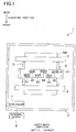
- the direction in which a recording sheet 100 is conveyed in Fig. 1 is defined as the front and rear direction of the printer 1.
- the widthwise direction of the recording sheet 100 is defined as the right and left direction of the printer 1.
- the direction orthogonal to the front and rear direction and the right and left direction and perpendicular to the sheet surface of Fig. 1 is defined as the up and down direction of the printer 1.
- the printer 1 includes a housing 2 that contains a platen 3, an ink-jet head 4, two conveying rollers 5, 6, and a controller 7.
- the conveying rollers 5, 6 are respectively disposed at a rear of and in front of the platen 3.
- the conveying rollers 5, 6 are rotated by a motor, not illustrated, to convey the recording sheet 100 frontward on the platen 3.
- the ink-jet head 4 is disposed above the platen 3 and extends throughout the entire width of the recording sheet 100 in the right and left direction. Inks of four colors, namely, yellow, cyan, magenta, and black are supplied to the ink-jet head 4 respectively from main tanks 11, which will be described below. Detail construction of the ink-jet head 4 will be described later.
- the controller 7 includes a central processing unit (CPU), a read only memory (ROM), a random access memory (RAM), and an application-specific integrated circuit (ASIC) including various kinds of control circuits.
- the controller 7 further includes a non-transitory memory configured to store control parameters rewritably.
- the controller 7 is connected to an external device 8 such as a personal computer (PC) for data communication.
- the controller 7 controls devices of the printer 1, such as the ink-jet head 4 and the motor, based on image data transmitted from the external device 8.
- the controller 7 controls the motor such that the conveying rollers 5, 6 convey the recording sheet 100 in the conveying direction. During this control, the controller 7 controls the ink-jet head 4 to eject the ink onto the recording sheet 100 to form an image on the recording sheet 100.
- Fig. 2 schematically illustrates ink passages for the four colors between the ink-jet head 4 and the main tanks 11.
- Fig. 3 principally illustrates a passage for yellow ink by way of example. It is noted that Fig. 3 includes: a cross-sectional view of an ink supply unit 30, which will be described below, taken along a plane orthogonal to the front and rear direction; and schematic views of the other components.
- the ink-jet head 4 includes six ejection modules 21-26 and the ink supply unit 30 configured to supply the inks to the ejection modules 21-26.
- the inks are supplied to the ink-jet head 4, from the respective main tanks 11 for the four colors, via respective sub-tanks 12 configured to temporarily store the respective inks.
- each of the sub-tanks 12 and the ink-jet head 4 are connected to each other by two passages.
- a corresponding one of diaphragm pumps 13 is provided on one of the two passages.
- the diaphragm pump 13 is configured to circulate the ink between the ink-jet head 4 and the sub-tank 12. Detailed connection of these components will be described later.
- the ink-jet head 4 includes the ejection modules 21-26 and the ink supply unit 30.
- the six ejection modules 21-26 are arranged in a staggered configuration.
- the ejection modules 22, 24, 26 are arranged in a row in the right and left direction, and the ejection modules 21, 23, 25 are arranged in a row in the right and left direction.
- Each of the ejection modules 21, 23, 25 is located on a front right side of a corresponding one of the ejection modules 22, 24, 26.
- Each of the ejection modules 21-26 has four nozzle rows 27 respectively corresponding to the four colors and ejects the inks of the respective four colors.
- the ink supply unit 30 includes a supply member 31 and a damper member 32.
- the supply member 31 has the four supply chambers 33.
- Each of the supply chambers 33 is defined for supplying the ink to the ejection modules 21-26.
- one of suffixes y, c, m, and k may be selectively added as needed to the reference numbers of components to indicate their respective correspondences with one of the yellow, cyan, magenta, and black inks.
- the supply chamber 33 for the yellow ink may be referred to as "supply chamber 33y”.
- the supply chamber 33 for the yellow ink may be referred to as "yellow supply chamber 33y”.
- the construction of the supply member 31 will be described with reference to Figs. 3-5 .
- the supply member 31 has a substantially rectangular parallelepiped shape and defines therein the four supply chambers 33.
- the supply chamber 33y, 33c, 33m, 33k each extending in the right and left direction are arranged in the front and rear direction.
- W1y the width of the yellow supply chamber 33y in the front and rear direction is defined as W1y.
- the yellow supply chamber 33y will be described by way of example. As illustrated in Figs. 3 and 5A , the yellow supply chamber 33y has openings 41y-43y.
- the openings 41y, 42y are respectively formed in left and right end portions of an upper wall defining the supply chamber 33y, i.e., an upper wall 44 of the supply member 31.
- the opening 43y is formed in the upper wall 44 at its substantially central portion in the right and left direction.
- the supply chamber 33y has openings 51y-56y.
- the openings 51y-56y are formed in the supply chamber 33y so as to be arranged in the right and left direction.
- the openings 51y-56y respectively communicate with the ejection modules 21-26 through the tubes 57y-62y, for example.
- the left three openings 51y-53y are formed between the opening 41y and the opening 43y in the right and left direction.
- the right three openings 54y-56y are formed between the opening 42y and the opening 43y in the right and left direction.
- the supply chamber 33y is covered with the wall except the openings 41y-43y and the openings 51y-56y.
- the area of the supply chamber 33y in cross section orthogonal to the right and left direction at a region located between the opening 43y and each of the openings 51y-56y in the right and left direction is greater than the area of each of the openings 41y, 42y.
- the above-described cross-sectional area is greater than the area of each of the openings 41y, 42y at a region located between the opening 51y and the opening 56y in the right and left direction.
- the opening 51y and the opening 56y are the furthest pair among the openings 51 y-56y, and the opening 43y is interposed between the opening 51y and the opening 56y in the right and left direction.
- the constructions of the respective supply chambers 33c, 33m, 33k are similar to that of the supply chamber 33y.
- the supply chamber 33c has openings 41c-43c
- the supply chamber 33m has openings 41m-43m
- the supply chamber 33k has openings 41k-43k.
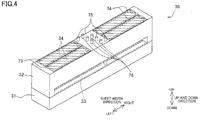
- the damper member 32 has a substantially rectangular parallelepiped shape and defines therein four damper chambers 34. Each of the damper chambers 34 relieves changes of a pressure of the ink in a corresponding one of the supply chambers 33. Each of the damper chambers 34 extends in the right and left direction. The length of the damper member 32 in the right and left direction is substantially equal to that of the supply member 31 in the right and left direction. The width W2 of the damper member 32 in the front and rear direction is substantially equal to the width W1 of the supply member 31 in the front and rear direction.
- the damper member 32 is superposed on the supply member 31. That is, the four damper chambers 34 are located above the four supply chambers 33.
- the damper member 32 is partitioned into upper and lower portions by an inner wall 65 extending in the right and left direction. As illustrated in Figs. 4 and 5B , the damper member 32 is also partitioned into front and rear portions.
- the damper chamber 34y and the damper chamber 34c overlap each other in the up and down direction
- the damper chamber 34m and the damper chamber 34k overlap each other in the up and down direction.
- the damper chamber 34y and the damper chamber 34m are arranged in the front and rear direction.
- the damper chamber 34c and the damper chamber 34k are arranged in the front and rear direction under the damper chamber 34y and the damper chamber 34m.
- the damper chamber 34y and the supply chamber 33y overlap each other in the up and down direction.
- the width W2y of the damper chamber 34y in the front and rear direction is half of the width W2.
- the width W2y is about twice the width W1y.
- the damper chamber 34y will be described by way of example. As illustrated in Fig. 3 , the damper chamber 34y has openings 66y-68y. The opening 66y is formed in a left end portion of the inner wall 65, and the opening 67y is formed in a right end portion of the inner wall 65. Communication passages 45y, 46y extend downward from the respective openings 66y, 67y. The opening 68y is formed in an upper wall 69 of the damper member 32 at its substantially central portion in the right and left direction.
- the upper wall 69 defining the damper chamber 34y is partly constituted by resin films 73y, 74y.
- the resin films 73y, 74y are hatched in Figs. 4 and 5B .
- the resin films 73y, 74y are deformed so as to protrude, which relieves the rise in the pressure.
- the resin films 73y, 74y are deformed so as to be recessed, which relieves the lowering of the pressure.
- a communication passage 77y extends downward from the connector 75y through the damper chamber 34y to the opening 43y of the supply chamber 33y.
- a tube defining the communication passage 77y is narrow, and this communication passage 77y does not inhibit a flow of the ink in the damper chamber 34y in the right and left direction.
- the connector 76y communicates with the opening 68y of the damper chamber 34y.
- the constructions of the damper chambers 34 for the other ink colors are generally similar to that of the damper chamber 34y. However, as illustrated in Fig. 3 , the resin films 73c, 74c of the damper chamber 34c are formed in the lower wall 78 of the damper member 32. The construction of the damper chamber 34k is similar to that of the damper chamber 34c. It is noted that Fig. 3 omits illustration of, e.g., the communication passages extending from the damper chamber 34c to the sub-tank 12c.
- the supply chamber 33y is connected to the damper chamber 34y by the communication passages 45y, 46y. That is, the openings 41y, 42y of the supply chamber 33y communicate with the respective openings 66y, 67y of the damper chamber 34y through the respective communication passages 45y, 46y.
- the supply chamber 33y is connected to the sub-tank 12y by the communication passage 77y and the tube 47y. That is, the opening 43y of the supply chamber 33y communicates with the sub-tank 12y through the communication passage 77y and the tube 47y attached to the connector 75y.
- the supply chamber 33y has the opening 43y directly communicating with the sub-tank 12y without communicating with the damper chamber 34y, in addition to the openings 41y, 42y communicating with the damper chamber 34y. That is, this printer 1 is not configured such that the damper chamber 34y is disposed between the sub-tank 12y and the supply chamber 33y.
- the ink passages for the other ink colors also have the above-described connection relationship among the components. Focusing on the supply chamber 33c, for example, the openings 41c, 42c communicate with the respective openings 66c, 67c of the damper chamber 34c. The opening 43c different from the openings 41c, 42c communicates with the sub-tank 12c.
- the ink passages for the magenta ink and the black ink have the similar construction.
- the damper chamber 34y is connected to the sub-tank 12y by tubes 71y, 72y.
- a diaphragm pump 13y is provided between the damper chamber 34y and the sub-tank 12y. That is, the opening 68y of the damper chamber 34y communicates through the tube 72y with an outlet 84 of the diaphragm pump 13y, which will be described below.
- the sub-tank 12y is connected by the tube 71y to an inlet 83 of the diaphragm pump 13y, which will be described below.
- the sub-tank 12y is connected to a main tank 11y by a tube 40y.
- the supply chamber 33y is connected to the damper chamber 34y and the sub-tank 12y, and the damper chamber 34y is connected to the sub-tank 12y.
- This construction forms a circulation passage in which the liquid having flowed from the sub-tank 12y flows back to the sub-tank 12y through the damper chamber 34y and the supply chamber 33y.
- the ink passages for the other colors also have the connection relationship described above.
- the diaphragm pump 13 includes: a pressure chamber 82 having a diaphragm 81; the inlet 83; the outlet 84; a check ball 85 disposed near the inlet 83; and a check ball 86 disposed near the outlet 84.
- the inlet 83 is connected to the sub-tank 12 by the tube 71
- the outlet 84 is connected to the damper chamber 34 by the tube 72.
- the diaphragm pump 13 is connected to a pump shaft, not illustrated.
- the ink flows in the ink passages in two ways.
- One of the ways is a flow of the ink supplied from the sub-tank 12 to the supply chamber 33 during printing, i.e., ink ejection.
- the other of the ways is a flow of the ink back to the sub-tank 12 through the sub-tank 12, the damper chamber 34, and the supply chamber 33 in maintenance. That is, the other of the ways is a flow of the circulation of the ink in maintenance.
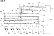
- the ink flow in printing will be described with reference to Fig. 7 .
- Fig. 7 is a conceptual view illustrating a flow of the yellow ink in printing.
- the diaphragm pump 13y is not operated during printing to prevent the ink from flowing from the sub-tank 12y into the damper chamber 34y.
- the supply chamber 33y and the damper chamber 34y are filled with the ink.
- the controller 7 controls the ink-jet head 4 to eject the ink from the ejection modules 21-26.
- the ink stored in the sub-tank 12y is supplied through the tube 47y and the communication passage 77y to the central portion of the supply chamber 33y in the right and left direction.
- the supply chamber 33y is replenished with the ink.
- This ink flow is similar to flows of the inks of the other colors.
- the resin films 73, 74 of the damper chamber 34 relieve the change of ink pressure as described above.
- the resin films 73, 74 permit passage of gas therethrough, which may cause increase in viscosity of the ink and/or generation of air bubbles. Flow of the high-viscosity ink or the air bubbles into the ejection modules 21-26 may cause failure of ink ejection from the nozzles. If the damper chamber 34 is disposed between the sub-tank 12 and the supply chamber 33, all the high-viscosity ink flows into the ejection modules 21-26.
- the openings 41, 42 of the supply chamber 33 of the ink supply unit 30 communicate with the damper chamber 34, and the opening 43 communicates with the sub-tank 12 independently of the communication of the openings 41, 42 with the damper chamber 34. That is, this printer 1 is not configured such that the damper chamber 34 is disposed between the sub-tank 12 and the supply chamber 33. Accordingly, even if increase in viscosity of the ink and/or generation of the air bubbles have occurred in the damper chamber 34, it is possible to make it more difficult for the high-viscosity ink and/or the air bubbles to flow into the ejection modules 21-26 in ink ejection from the ejection modules 21-26.
- the openings 51-53 communicating with the respective ejection modules 21-23 are formed between the opening 41 and the opening 43 of the supply chamber 33.
- the openings 54-56 communicating with the respective ejection modules 24-26 are formed between the opening 42 and the opening 43.
- the supplied ink is prone to flow to right and left end portions of the supply chamber 33 later than to its central portion.
- the openings 42, 41 are formed at the respective right and left end portions of the supply chamber 33.
- the ink is also supplied from the damper chamber 34 via the end portions of the supply chamber 33, resulting in reduction in the drop of the liquid pressure in the supply chamber 33.
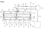
- Fig. 8 is a conceptual view illustrating a flow of the yellow ink in maintenance.
- the controller 7 actuates the diaphragm pump 13y in a state in which printing is not performed, i.e., in a state in which the ink is not ejected from the ejection modules 21-26. This actuation is performed when a predetermined period is elapsed from the previous maintenance, for example.
- the diaphragm pump 13y forces the ink from the sub-tank 12y through the tube 72y to the central portion of the damper chamber 34y in the right and left direction.
- High-viscosity ink and air bubbles in the damper chamber 34y are pushed rightward and leftward by the forced ink and transferred into the supply chamber 33y via the communication passages 45y, 46y.
- the transferred high-viscosity ink and air bubbles flow in the supply chamber 33y, then flow out of the supply chamber 33y from the opening 43y formed in the central portion of the supply chamber 33y in the right and left direction, finally flow back to the sub-tank 12y through the communication passage 77y and the tube 47y.
- the direction of the ink flow in printing and the direction of the ink flow in maintenance are reverse from each other.
- the circulation passage is formed in which the ink flows back to the sub-tank 12 through the sub-tank 12, the damper chamber 34, and the supply chamber 33.
- the diaphragm pump 13 disposed between the sub-tank 12 and the damper chamber 34 circulates the ink in the circulation passage to discharge high-viscosity ink and air bubbles from the damper chamber 34. This construction reduces inflows of the high-viscosity ink and air bubbles into the ejection modules 21-26 in ink ejection from the ejection modules 21-26.
- the diaphragm pump 13 preferably forces the ink at a high pressure in maintenance in order to reliably discharge high-viscosity ink and air bubbles from the damper chamber 34. If the ink is transferred from the sub-tank 12 toward the supply chamber 33, however, the pressure of the ink may excessively rise in the supply chamber 33 just after the forcing of the ink from the diaphragm pump 13, leading to leakage of the ink from the ejection modules 21-26. In the present embodiment, however, the ink is circulated in maintenance in the direction reverse to that in printing, that is, the ink is circulated in maintenance in the order of the sub-tank 12, the damper chamber 34, the supply chamber 33, and the sub-tank 12. In this case, the ink leakage is prevented because the pressure in the supply chamber 33 is low due to pressure loss caused when the ink passes through the openings 41, 42 and the like.
- the ink gets hard to flow if the area of the supply chamber 33 in cross section orthogonal to the right and left direction at the region located between the opening 43 and each of the openings 51-56 in the right and left direction.
- the pressure of the ink having flowed from the openings 41, 42 becomes high at a position near the openings 51-56, which may lead to leakage of the ink from the ejection modules 21-26.
- the above-described cross-sectional area is large at the region between the opening 43 and each of the supply openings in the right and left direction.
- the ink flow in the supply chamber 33 is not easily hindered, thereby avoiding the ink leakage from the ejection modules 21-26.
- the diaphragm pump 13 includes the check ball 85 near the inlet 83 and the check ball 86 near the outlet 84.
- the inlet 83 and the outlet 84 are respectively closed by the check ball 85 and the check ball 86 at rest of the diaphragm pump 13, so that the ink does not flow through the tubes 71, 72. Accordingly, it is possible to prevent the ink from flowing from the sub-tank 12 to the damper chamber 34 in ink ejection.
- Each of the one end portion and the other end portion of the damper chamber 34 is connected to the supply chamber 33. That is, the end portions of the damper chamber 34 are not blind. This construction enables smooth circulation of the ink in the damper chamber 34.
- the wall defining the damper chamber 34 is at least partly constituted by the resin films 73, 74.
- the changes of the ink pressure in the supply chamber 33 are effectively reduced, but the resin films 73, 74 permit passage of gas therethrough, which may cause increase in viscosity of the ink and generation of the air bubbles.
- the printer 1 is not configured such that the damper chamber 34 is disposed between the sub-tank 12 and the supply chamber 33, making it more difficult for the high-viscosity ink and/or the air bubbles to flow into the ejection modules 21-26 in the ejection of the liquid from the ejection modules 21-26.
- the damper chamber 34 is disposed above the supply chamber 33, preventing the air bubbles from flowing into the supply chamber 33.
- the damper chamber 34y and the damper chamber 34c are not arranged in the front and rear direction but overlap each other in the up and down direction. Accordingly, the total area of the two supply chambers 33 is provided for each of the damper chambers 34, enabling increase in the area of the resin films 73, 74.
- the damper chamber 34y is situated above the supply chamber 33y, and the openings 41y, 42y of the supply chamber 33y are formed in the upper wall 44 of the supply member 31.
- the communication passage 45y connecting the supply chamber 33y and the damper chamber 34y to each other is short, resulting in compact layout.
- the opening 43y is formed in the upper wall 44 of the supply member 31, resulting in compact layout.
- the printer 1 is one example of a liquid ejection apparatus.
- the ink is one example of liquid.
- the front and rear direction is one example of an arrangement direction.
- the right and left direction is one example of a longitudinal direction.
- Each of the sub-tanks 12 is one example of a tank.
- Each of the openings 41, 42 and the openings 41y, 42y is one example of a first opening.
- Each of the opening 43 and 43y is one example of a second opening.
- Each of the communication passages 45y, 46y is one example of a first connection passage.
- Each of the communication passage 77y and the tube 47y is one example of a second connection passage.
- Each of the openings 51-56 is one example of a supply opening.
- Each of the diaphragm pumps 13 is one example of a pump.
- Each of the tubes 71, 72 is one example of a liquid passage.
- the check ball 85 is one example of an inlet valve.
- the check ball 86 is one example
- the yellow ink is one example of first liquid.
- the cyan ink is one example of second liquid.
- the sub-tank 12y is one example of a first tank.
- the sub-tank 12c is one example of a second tank.
- the supply chamber 33y is one example of a first supply chamber.
- the supply chamber 33c is one example of a second supply chamber.
- the damper chamber 34y is one example of a first damper chamber.
- the damper chamber 34c is one example of a second damper chamber.
- Each of the openings 41c, 42c is one example of a third opening.
- the opening 43c is one example of a fourth opening.
- Each of the resin films 73y, 74y is one example of a first resin film.
- Each of the resin films 73c, 74c is one example of a second resin film.
- Each of the communication passages 45c, 46c is one example of a third connection passage.
- Each of the communication passage 77c and the tube 47c is one example of a fourth connection passage.
- the ink supply unit 30 is one example of a liquid supply unit.
- the wall defining the supply chamber may be partly constituted by a resin film.
- Fig. 9 illustrates a supply member 89 having a supply chamber 90y. A portion of the supply chamber 90y which is located between the opening 41y and the opening 43y is defined by a resin film 91y. A portion of the supply chamber 90y which is located between the opening 42y and the opening 43y is defined by a resin film 92y.
- the width of the damper chamber 34y in the front and rear direction is about twice the width of the supply chamber 90y in the front and rear direction. That is, the total area of the resin films 91y, 92y of the supply chamber 90y is less than that of the resin films 73y, 74y of the damper chamber 34y.
- the resin films 91y, 92y relieve changes of the pressure of the yellow ink in the supply chamber 90y in printing, increase in viscosity of the ink and generation of air bubbles may occur in the supply chamber 90y.
- the supply chamber 90y has the function of relieving the changes of the ink pressure like the damper chamber 34y, but the damper chamber 34y defined by the resin films 73y, 74y having a relatively large total area is one example of a first damper chamber.
- This construction achieves an effect of reducing a flow of the high-viscosity ink into the supply chamber 90y.
- each of the resin films 91y, 92y is one example of a third resin film.
- the constructions of the supply member 31 and the damper member 32 are not limited to those in the above-described embodiment.
- the width W1 of the supply member 31 in the front and rear direction and the width W2 of the damper member 32 in the front and rear direction may not be substantially equal to each other.
- Each of the supply member 31 and the damper member 32 may not have the substantially rectangular parallelepiped shape.
- the four supply chambers 33 may be constituted by different members.
- the four damper chambers 34 may be constituted by different members.
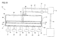
- Fig. 10 illustrates a damper member 94 is not partitioned into an upper portion and a lower portion. Though not illustrated, a supply member 93 is not partitioned into a front portion and a rear portion and has only one supply chamber 95. Likewise, though not illustrated, the damper member 94 is not partitioned into a front portion and a rear portion and has only one damper chamber 96.
- the positions of the openings of the supply chamber and the damper chamber may be changed.
- the opening 41 is formed in a left end portion of the supply chamber 95
- the opening 43 is formed in a right end portion of the supply chamber 95.
- the opening 68 is formed in a right end portion of the damper chamber 96. That is, a left end portion of the damper chamber 96 and the supply chamber 95 are connected to each other, and the right end portion of the damper chamber 96 and the sub-tank 12 are connected to each other.
- the ink is supplied from the damper chamber 96 to the left end portion of the supply chamber 95 to relieve the drop of the ink pressure in the supply chamber.
- the end portions of the damper chamber 96 are not blind.
- the diaphragm pump 13 when the diaphragm pump 13 is actuated, all the ink in the damper chamber 96 is discharged without remaining, so that high-viscosity liquid and air bubbles are circulated and transferred back to the sub-tank 12. Accordingly, it is possible to prevent the high-viscosity liquid and the air bubbles from flowing into the ejection modules 21-26 in liquid ejection from the ejection modules 21-26.
- the sub-tank may not be provided between the ink-jet head 4 and the main tank 11.
- the main tank 11 is connected to the diaphragm pump 13 by a tube 98 and to the supply chamber 95 by a tube 99. With this construction, the ink is directly supplied from the main tank 11 to the supply chamber 95 in printing. In maintenance, the diaphragm pump 13 forces the ink from the main tank 11 to the damper chamber 96.
- the main tank 11 is one example of the tank.
- the direction of the ink flow in maintenance may coincide with the direction of the ink flow in printing.
- the printer 1 may be constructed such that the inlet 83 of the diaphragm pump 13 is connected to the tube 72, and the outlet 84 is connected to the tube 71.
- the diaphragm pump 13 sucks the ink from the damper chamber 96 and transfers the ink toward the sub-tank 12, so that the ink in the sub-tank is transferred toward the supply chamber 95.
- the pump is not limited to the diaphragm pump 13.
- a suction pump may be used to suck high-viscosity ink from the damper chamber 34 and the like to circulate the ink.
- the openings 66, 67 of the damper chamber 34 may not be formed at the opposite end portions of the damper chamber 34 in the right and left direction, for example.
- Each of the openings 51-56 respectively communicating with the ejection modules 21-26 may be formed between the opening 41 and the opening 43 or between the opening 42 and the opening 43.
- the ink supply unit 30 may not include the diaphragm pump 13 so as not to circulate the ink. Also in this construction, since the damper chamber 96 is not disposed between the sub-tank 12 and the supply chamber 95, it is possible to make it more difficult for the high-viscosity ink and/or the air bubbles to flow into the ejection modules 21-26.
- the ink-jet head 4 is a line head that is not moved with respect to the recording sheet 100 during printing.
- the ink-jet head 4 may be a serial head configured to eject the ink while moving in the right and left direction.
- the present disclosure has been applied to the printer configured to eject the ink to perform printing, but the present disclosure is not limited to this configuration.
- the present disclosure may be applied to liquid ejection apparatuses configured to eject liquid other than the ink, such as materials of wiring patterns for wiring substrates.
Landscapes
- Ink Jet (AREA)
Abstract
Description
- The following disclosure relates to a liquid ejection apparatus and a liquid supply unit.
- Patent Document 1 (Japanese Patent Application Publication No.
2014-46577 - The flexible film permits passage of gas therethrough. Thus, water in the ink vaporizes during, e.g., waiting, which may easily lead to increase in viscosity of the ink in the damper chamber. Also, air bubbles are easily generated because outside air enters the damper chamber by passing through the flexible film. In the above-described liquid ejection apparatus, the tank, the damper chamber, and the ejection modules are arranged in series. Thus, all the ink in the damper chamber is supplied to the ejection modules in printing. Accordingly, the high-viscosity ink and the air bubbles may flow into the ejection modules, leading to failure of ink ejection from the nozzles, for example.
- Accordingly, an aspect of the disclosure relates to a technique of preventing high-viscosity liquid and air bubbles generated in a damper chamber from flowing into the ejection module.
- In one aspect of the disclosure, a liquid ejection apparatus includes: an ejection module; a supply chamber connected to the ejection module and to a tank configured to store liquid; and a damper chamber connected to the supply chamber. The supply chamber has: a first opening communicating with the damper chamber; and a second opening communicating with the tank.
- In the liquid ejection apparatus described above, the supply chamber connected to the ejection module has the second opening directly communicating with the tank not via the damper chamber, independently of the first opening communicating with the damper chamber. That is, the liquid ejection apparatus is not configured such that the damper chamber is disposed between the tank and the supply chamber. Accordingly, even if increase in viscosity of the liquid and/or generation of the air bubbles has occurred in the damper chamber, it is possible to make it more difficult for the high-viscosity liquid and/or the air bubbles to flow into the ejection module in liquid ejection from the ejection module.
- The liquid ejection apparatus further includes: a first connection passage connecting the first opening and the damper chamber to each other; and a second connection passage connecting the second opening and the tank to each other.
- In the liquid ejection apparatus, the supply chamber has a supply opening communicating with the ejection module, and the supply opening is located between the first opening and the second opening.
- The supply opening communicating with the ejection module is formed between the first opening and the second opening of the supply chamber. When an amount of liquid consumption in the ejection module is large, supply of the liquid from the tank to the ejection module cannot keep up with the liquid consumption, leading to a significant decrease in the liquid pressure in the supply chamber. In the liquid ejection apparatus described above, however, since the supply opening is formed between the first opening and the second opening, the liquid is also temporarily supplied from the damper chamber to the supply chamber via the first opening. This liquid supply reduces the decrease in pressure of the liquid in the supply chamber.
- In the liquid ejection apparatus, the supply chamber is elongated in a first direction. The first opening is located at an end portion of the supply chamber in the first direction.
- Supplied liquid is prone to delay at an end portion of the supply chamber in the first direction. In the liquid ejection apparatus described above, the first opening is formed at the end portion of the supply chamber in the first direction. Thus, the liquid is also supplied from the damper chamber via the end portion of the supply chamber, resulting in reduction in decrease in pressure of the liquid in the supply chamber.
- In the liquid ejection apparatus, the supply chamber is elongated in a first direction. The first opening is located at a first end portion of the supply chamber in the first direction. The second opening is located at a second end portion of the supply chamber in the first direction.
- In the liquid ejection apparatus described above, the first opening is located at the first end portion of the supply chamber in the first direction, and the second opening is located at the second end portion of the supply chamber in the first direction. The liquid is also supplied from the damper chamber via the first end portion of the supply chamber, resulting in reduction in decrease in pressure of the liquid in the supply chamber.
- The liquid ejection apparatus further includes: a liquid passage connecting the damper chamber and the tank to each other; and a pump disposed at a portion of the liquid passage.
- In the liquid ejection apparatus described above, a circulation passage is formed in which the liquid flows back to the tank through the tank, the damper chamber, and the supply chamber. The pump disposed between the tank and the damper chamber circulates the liquid in the above-described passage to discharge high-viscosity liquid and air bubbles from the damper chamber. This construction reduces inflows of high-viscosity liquid and air bubbles into the ejection module in liquid ejection from the ejection module.
- In the liquid ejection apparatus, an outlet of the pump is connected to the damper chamber.
- In the liquid circulation, the liquid may flow through the components in any of the order of the tank, the damper chamber, the supply chamber, and the tank (first order) and in the order of the tank, the supply chamber, the damper chamber, and the tank (second order). Here, the pump preferably forces the liquid at a high pressure in order to reliably discharge high-viscosity liquid and air bubbles from the damper chamber. In the case where the liquid is circulated in the second order, however, the pressure of the liquid may excessively rise in the supply chamber just after the forcing of the liquid from the pump, leading to leakage of the liquid from the ejection module. In the liquid ejection apparatus described above, in contrast, the liquid is circulated in the first order. In this case, the liquid leakage is prevented because the pressure in the supply chamber is low due to pressure loss caused when the liquid passes through the first opening and the like.
- In the liquid ejection apparatus, the supply chamber is elongated in a first direction. The supply chamber has a supply opening communicating with the ejection module, and the supply opening is located between the first opening and the second opening in the first direction. A cross-sectional area of the supply chamber on a plane orthogonal to the first direction at a position located between the supply opening and the second opening in the first direction is greater than an area of the first opening.
- The liquid gets hard to flow if the cross-sectional area of the liquid passage of the supply chamber is small at the position located between the second opening and the supply opening in the first direction. As a result, the pressure of the liquid having flowed from the first opening becomes high at a position near the supply opening, which may lead to leakage of the liquid from the ejection module. In the present disclosure, however, the cross-sectional area of the liquid passage is large at the position between the second opening and the supply opening in the first direction. Thus, the liquid flow in the supply chamber is not easily hindered, thereby avoiding the liquid leakage from the ejection module.
- In the liquid ejection apparatus, the pump includes: a pressure chamber including a diaphragm; an inlet valve; and an outlet valve.
- The pump includes: the pressure chamber having the diaphragm; the inlet valve; and the outlet valve. Thus, the inlet and the outlet of the pump are respectively closed by the inlet valve and the outlet valve at rest of the pump, so that the liquid does not flow through the liquid passage. Accordingly, it is possible to prevent the liquid from flowing from the tank to the damper chamber in liquid ejection.
- In the liquid ejection apparatus, a first end portion of the damper chamber is connected to the supply chamber. A second end portion of the damper chamber is connected to the tank.
- The first end portion of the damper chamber and the supply chamber are connected to each other. The second end portion of the damper chamber and the tank are connected to each other. That is, the end portions of the damper chamber are not blind. With this construction, when the pump is actuated, a smaller amount of the liquid remains in the damper chamber. As a result, the liquid is smoothly discharged toward the supply chamber or the tank, so that high-viscosity liquid and air bubbles are circulated and transferred back to the tank. Accordingly, it is possible to prevent the high-viscosity liquid and the air bubbles from flowing into the ejection module in liquid ejection from the ejection module.
- In the liquid ejection apparatus, each of the first end portion and the second end portion of the damper chamber is connected to the supply chamber. A portion of the damper chamber which is located between the first end portion and the second end portion is connected to the tank.
- In the construction in which the damper chamber and the tank are connected to each other, the supply chamber is connected to each of the first end portion and the second end portion of the damper chamber, and the end portions of the damper chamber are not blind. This construction enables smooth circulation of the liquid in the damper chamber.
- In the liquid ejection apparatus, at least a portion of a wall defining the damper chamber is constituted by a resin film.
- The wall defining the damper chamber is at least partly constituted by the resin film. With this construction, changes of the pressure of the liquid in the supply chamber are effectively reduced, but the resin film permits passage of gas therethrough, which may cause increase in viscosity of the liquid and generation of air bubbles. The liquid ejection apparatus described above is not configured such that the damper chamber is disposed between the tank and the supply chamber, making it more difficult for the high-viscosity liquid and/or the air bubbles to flow into the ejection module in the ejection of the liquid from the ejection module.
- In the liquid ejection apparatus, the damper chamber is disposed above the supply chamber.
- If the supply chamber is situated above the damper chamber, air having entered the damper chamber through the resin film may become air bubbles and flow into the supply chamber. In the liquid ejection apparatus described above, the damper chamber is disposed above the supply chamber, preventing the air bubbles from flowing into the supply chamber.
- In another aspect of the disclosure, a liquid ejection apparatus includes: an ejection module; a first supply chamber connected to the ejection module and to a first tank configured to store first liquid; a first damper chamber connected to the first supply chamber; a second supply chamber connected to the ejection module and to a second tank configured to second liquid; and a second damper chamber connected to the second supply chamber. Each of the first supply chamber, the second supply chamber, the first damper chamber, and the second damper chamber is elongated in the first direction as a longitudinal direction. The first supply chamber has: a first opening communicating with the first damper chamber; and a second opening communicating with the first tank. The second supply chamber has: a third opening communicating with the second damper chamber; and a fourth opening communicating with the second tank. At least a portion of a wall defining the first damper chamber is constituted by a first resin film. At least a portion of a wall defining the second damper chamber is constituted by a second resin film. The first supply chamber and the first damper chamber overlap each other when viewed in an up and down direction. The first supply chamber and the second supply chamber are arranged in an arrangement direction orthogonal to each of the longitudinal direction and the up and down direction. The first damper chamber and the second damper chamber overlap each other when viewed in the up and down direction.
- The liquid ejection apparatus includes the plurality of supply chambers and the plurality of damper chambers each connected to a corresponding one of the tanks. The damper chamber is not disposed between the tank and the supply chamber, making it difficult for air bubbles and/or the liquid whose viscosity has increased in the damper chamber to flow into the ejection module. While the first supply chamber and the second supply chamber are arranged in the arrangement direction, the first damper chamber and the second damper chamber are not arranged in the arrangement direction but overlap each other in the up and down direction. Accordingly, the total area of the first supply chamber and the second supply chamber is provided for the one damper chamber, enabling increase in the area of the resin film.
- The liquid ejection apparatus further includes: a first connection passage connecting the first opening and the first damper chamber to each other; a second connection passage connecting the second opening and the first tank to each other; a third connection passage connecting the third opening and the second damper chamber to each other; and a fourth connection passage connecting the fourth opening and the second tank.
- In the liquid ejection apparatus, the first damper chamber is disposed above the first supply chamber. The first opening is formed in an upper wall defining the first supply chamber.
- The first damper chamber is situated above the first supply chamber, and the first opening of the first supply chamber is formed in the upper wall defining the supply chamber. Thus, the communication passage connecting the first supply chamber and the first damper chamber to each other is short, resulting in compact layout.
- In the liquid ejection apparatus, the second opening is formed in the upper wall defining the first supply chamber.
- Like the first opening, the second opening is formed in the upper wall defining the supply chamber, resulting in compact layout.
- In the liquid ejection apparatus, a portion of the upper wall defining the first supply chamber which portion is located between the first opening and the second opening in the first direction is constituted by a third resin film with an area that is less than an area of the first resin film.
- While the third resin film relieves changes of pressure of the first liquid in the first supply chamber in liquid ejection, increase in viscosity of the liquid and generation of air bubbles may occur. However, since the area of the third resin film defining the first supply chamber is less than that of the first resin film defining the first damper chamber, the increase in viscosity of the liquid and the like have smaller effects.
- In yet another aspect of the disclosure, a liquid supply unit includes: a supply chamber connected to the ejection module and to a tank configured to store liquid; and a damper chamber connected to the supply chamber. The supply chamber has: a first opening communicating with the tank; and a second opening communicating with the damper chamber.
- The liquid supply unit described above includes: the supply chamber connected to the ejection module and to the tank; and the damper chamber connected to the supply chamber. The supply chamber has: the first opening communicating with the tank; and the second opening communicating with the damper chamber. That is, the damper chamber is not disposed between the tank and the supply chamber.
- The objects, features, advantages, and technical and industrial significance of the present disclosure will be better understood by reading the following detailed description of the embodiment, when considered in connection with the accompanying drawings, in which:
-
Fig. 1 is a schematic plan view of a printer according to the present embodiment; -
Fig. 2 is a view illustrating ink passages for four colors which are formed between an ink-jet head and main tanks; -
Fig. 3 is a view illustrating ejection modules and an ink passage for one color; -
Fig. 4 is a perspective view of an ink supply unit; -
Fig. 5A is a plan view of a supply member, andFig. 5B is a plan view of a damper member; -
Figs. 6A-6C are schematic cross-sectional views of a diaphragm pump; -
Fig. 7 is a conceptual view illustrating ink flow during printing; -
Fig. 8 is a conceptual view illustrating ink flow during maintenance; -
Fig. 9 is a view illustrating ejection modules and an ink passage for one color in a modification; -
Fig. 10 is a view illustrating ejection modules and an ink passage for one color in another modification; -
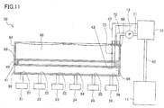
Fig. 11 is a view illustrating ejection modules and an ink passage for one color in yet another modification; and -
Fig. 12 is a view illustrating ejection modules and an ink passage for one color in yet another modification. - Hereinafter, there will be described one embodiment by reference to the drawings. The direction in which a
recording sheet 100 is conveyed inFig. 1 is defined as the front and rear direction of the printer 1. The widthwise direction of therecording sheet 100 is defined as the right and left direction of the printer 1. The direction orthogonal to the front and rear direction and the right and left direction and perpendicular to the sheet surface ofFig. 1 is defined as the up and down direction of the printer 1. - As illustrated in
Fig. 1 , the printer 1 includes ahousing 2 that contains aplaten 3, an ink-jet head 4, two conveyingrollers 5, 6, and acontroller 7. - An upper surface of the
platen 3 supports therecording sheet 100. The conveyingrollers 5, 6 are respectively disposed at a rear of and in front of theplaten 3. The conveyingrollers 5, 6 are rotated by a motor, not illustrated, to convey therecording sheet 100 frontward on theplaten 3. - The ink-
jet head 4 is disposed above theplaten 3 and extends throughout the entire width of therecording sheet 100 in the right and left direction. Inks of four colors, namely, yellow, cyan, magenta, and black are supplied to the ink-jet head 4 respectively frommain tanks 11, which will be described below. Detail construction of the ink-jet head 4 will be described later. - The
controller 7 includes a central processing unit (CPU), a read only memory (ROM), a random access memory (RAM), and an application-specific integrated circuit (ASIC) including various kinds of control circuits. Thecontroller 7 further includes a non-transitory memory configured to store control parameters rewritably. Thecontroller 7 is connected to anexternal device 8 such as a personal computer (PC) for data communication. Thecontroller 7 controls devices of the printer 1, such as the ink-jet head 4 and the motor, based on image data transmitted from theexternal device 8. - More specifically, the
controller 7 controls the motor such that the conveyingrollers 5, 6 convey therecording sheet 100 in the conveying direction. During this control, thecontroller 7 controls the ink-jet head 4 to eject the ink onto therecording sheet 100 to form an image on therecording sheet 100. - There will be next explained the ink-
jet head 4 and components connected thereto with reference toFigs. 1-3 .Fig. 2 schematically illustrates ink passages for the four colors between the ink-jet head 4 and themain tanks 11.Fig. 3 principally illustrates a passage for yellow ink by way of example. It is noted thatFig. 3 includes: a cross-sectional view of anink supply unit 30, which will be described below, taken along a plane orthogonal to the front and rear direction; and schematic views of the other components. - As illustrated in
Fig. 2 , the ink-jet head 4 includes six ejection modules 21-26 and theink supply unit 30 configured to supply the inks to the ejection modules 21-26. The inks are supplied to the ink-jet head 4, from the respectivemain tanks 11 for the four colors, viarespective sub-tanks 12 configured to temporarily store the respective inks. It is noted that each of the sub-tanks 12 and the ink-jet head 4 are connected to each other by two passages. A corresponding one of diaphragm pumps 13 is provided on one of the two passages. Thediaphragm pump 13 is configured to circulate the ink between the ink-jet head 4 and the sub-tank 12. Detailed connection of these components will be described later. - There will be next explained the construction of the ink-
jet head 4 in detail. As described above, the ink-jet head 4 includes the ejection modules 21-26 and theink supply unit 30. As illustrated inFig. 1 , the six ejection modules 21-26 are arranged in a staggered configuration. Theejection modules ejection modules ejection modules ejection modules nozzle rows 27 respectively corresponding to the four colors and ejects the inks of the respective four colors. - As illustrated in
Fig. 3 , theink supply unit 30 includes asupply member 31 and adamper member 32. Thesupply member 31 has the foursupply chambers 33. Each of thesupply chambers 33 is defined for supplying the ink to the ejection modules 21-26. In the following description, one of suffixes y, c, m, and k may be selectively added as needed to the reference numbers of components to indicate their respective correspondences with one of the yellow, cyan, magenta, and black inks. For example, thesupply chamber 33 for the yellow ink may be referred to as "supply chamber 33y". It is noted that thesupply chamber 33 for the yellow ink may be referred to as "yellow supply chamber 33y". - The construction of the
supply member 31 will be described with reference toFigs. 3-5 . Thesupply member 31 has a substantially rectangular parallelepiped shape and defines therein the foursupply chambers 33. As illustrated inFig. 5A , thesupply chamber supply member 31 in the front and rear direction is defined as W1, and the width of theyellow supply chamber 33y in the front and rear direction is defined as W1y, the width W1y is about one fourth of the width W1. - The
yellow supply chamber 33y will be described by way of example. As illustrated inFigs. 3 and5A , theyellow supply chamber 33y hasopenings 41y-43y. Theopenings supply chamber 33y, i.e., anupper wall 44 of thesupply member 31. Theopening 43y is formed in theupper wall 44 at its substantially central portion in the right and left direction. - The
supply chamber 33y hasopenings 51y-56y. Theopenings 51y-56y are formed in thesupply chamber 33y so as to be arranged in the right and left direction. Theopenings 51y-56y respectively communicate with the ejection modules 21-26 through thetubes 57y-62y, for example. The left threeopenings 51y-53y are formed between theopening 41y and theopening 43y in the right and left direction. The right threeopenings 54y-56y are formed between theopening 42y and theopening 43y in the right and left direction. Thesupply chamber 33y is covered with the wall except theopenings 41y-43y and theopenings 51y-56y. - The area of the
supply chamber 33y in cross section orthogonal to the right and left direction at a region located between theopening 43y and each of theopenings 51y-56y in the right and left direction is greater than the area of each of theopenings openings opening 51y and theopening 56y in the right and left direction. Theopening 51y and theopening 56y are the furthest pair among theopenings 51 y-56y, and theopening 43y is interposed between theopening 51y and theopening 56y in the right and left direction. - The constructions of the
respective supply chambers supply chamber 33y. For example, thesupply chamber 33c hasopenings 41c-43c, thesupply chamber 33m hasopenings 41m-43m, and thesupply chamber 33k hasopenings 41k-43k. - There will be next explained the construction of the
damper member 32 with reference toFigs. 3-5B . Thedamper member 32 has a substantially rectangular parallelepiped shape and defines therein fourdamper chambers 34. Each of thedamper chambers 34 relieves changes of a pressure of the ink in a corresponding one of thesupply chambers 33. Each of thedamper chambers 34 extends in the right and left direction. The length of thedamper member 32 in the right and left direction is substantially equal to that of thesupply member 31 in the right and left direction. The width W2 of thedamper member 32 in the front and rear direction is substantially equal to the width W1 of thesupply member 31 in the front and rear direction. - The
damper member 32 is superposed on thesupply member 31. That is, the fourdamper chambers 34 are located above the foursupply chambers 33. - As illustrated in
Fig. 3 , thedamper member 32 is partitioned into upper and lower portions by aninner wall 65 extending in the right and left direction. As illustrated inFigs. 4 and5B , thedamper member 32 is also partitioned into front and rear portions. In the present embodiment, thedamper chamber 34y and thedamper chamber 34c overlap each other in the up and down direction, and thedamper chamber 34m and thedamper chamber 34k overlap each other in the up and down direction. Thedamper chamber 34y and thedamper chamber 34m are arranged in the front and rear direction. Thedamper chamber 34c and thedamper chamber 34k are arranged in the front and rear direction under thedamper chamber 34y and thedamper chamber 34m. Thedamper chamber 34y and thesupply chamber 33y overlap each other in the up and down direction. The width W2y of thedamper chamber 34y in the front and rear direction is half of the width W2. The width W2y is about twice the width W1y. - The
damper chamber 34y will be described by way of example. As illustrated inFig. 3 , thedamper chamber 34y hasopenings 66y-68y. Theopening 66y is formed in a left end portion of theinner wall 65, and theopening 67y is formed in a right end portion of theinner wall 65.Communication passages respective openings opening 68y is formed in anupper wall 69 of thedamper member 32 at its substantially central portion in the right and left direction. - The
upper wall 69 defining thedamper chamber 34y is partly constituted byresin films resin films Figs. 4 and5B . When the pressure of the ink in thesupply chamber 33y rises, theresin films resin films - As illustrated in
Figs. 4 and5B , fourconnectors 75 and fourconnectors 76 are disposed on a central portion of theupper wall 69 in the front and rear direction. Fourtubes 47 are attached to therespective connectors 75. Fourtubes 72 are attached to therespective connectors 76. Each of theconnectors Fig. 3 , acommunication passage 77y extends downward from theconnector 75y through thedamper chamber 34y to theopening 43y of thesupply chamber 33y. A tube defining thecommunication passage 77y is narrow, and thiscommunication passage 77y does not inhibit a flow of the ink in thedamper chamber 34y in the right and left direction. Theconnector 76y communicates with theopening 68y of thedamper chamber 34y. - The constructions of the
damper chambers 34 for the other ink colors are generally similar to that of thedamper chamber 34y. However, as illustrated inFig. 3 , theresin films damper chamber 34c are formed in thelower wall 78 of thedamper member 32. The construction of thedamper chamber 34k is similar to that of thedamper chamber 34c. It is noted thatFig. 3 omits illustration of, e.g., the communication passages extending from thedamper chamber 34c to the sub-tank 12c. - There will be next explained details of a connection relationship among the components with reference to
Fig. 3 . The following description will be provided for the ink passages for the yellow ink by way of example. - The
supply chamber 33y is connected to thedamper chamber 34y by thecommunication passages openings supply chamber 33y communicate with therespective openings damper chamber 34y through therespective communication passages supply chamber 33y is connected to the sub-tank 12y by thecommunication passage 77y and thetube 47y. That is, theopening 43y of thesupply chamber 33y communicates with the sub-tank 12y through thecommunication passage 77y and thetube 47y attached to theconnector 75y. - As thus described, the
supply chamber 33y has theopening 43y directly communicating with the sub-tank 12y without communicating with thedamper chamber 34y, in addition to theopenings damper chamber 34y. That is, this printer 1 is not configured such that thedamper chamber 34y is disposed between the sub-tank 12y and thesupply chamber 33y. - The ink passages for the other ink colors also have the above-described connection relationship among the components. Focusing on the
supply chamber 33c, for example, theopenings damper chamber 34c. Theopening 43c different from theopenings - The
damper chamber 34y is connected to the sub-tank 12y bytubes diaphragm pump 13y is provided between thedamper chamber 34y and the sub-tank 12y. That is, theopening 68y of thedamper chamber 34y communicates through thetube 72y with anoutlet 84 of thediaphragm pump 13y, which will be described below. The sub-tank 12y is connected by thetube 71y to aninlet 83 of thediaphragm pump 13y, which will be described below. The sub-tank 12y is connected to amain tank 11y by atube 40y. - As thus described, the
supply chamber 33y is connected to thedamper chamber 34y and the sub-tank 12y, and thedamper chamber 34y is connected to the sub-tank 12y. This construction forms a circulation passage in which the liquid having flowed from the sub-tank 12y flows back to the sub-tank 12y through thedamper chamber 34y and thesupply chamber 33y. The ink passages for the other colors also have the connection relationship described above. - There will be next explained the construction of each of the diaphragm pumps 13 with reference to
Figs. 6A-6C . Thediaphragm pump 13 includes: apressure chamber 82 having adiaphragm 81; theinlet 83; theoutlet 84; acheck ball 85 disposed near theinlet 83; and acheck ball 86 disposed near theoutlet 84. As described above, theinlet 83 is connected to the sub-tank 12 by thetube 71, and theoutlet 84 is connected to thedamper chamber 34 by thetube 72. Thediaphragm pump 13 is connected to a pump shaft, not illustrated. - When the
diaphragm pump 13 is not operated, as illustrated inFig. 6A , theinlet 83 and theoutlet 84 are respectively closed by thecheck balls diaphragm pump 13 is operated, the pump shaft vibrates thediaphragm 81. As illustrated inFig. 6B , when thediaphragm 81 is deformed so as to protrude, the pressure in thepressure chamber 82 lowers, so that thecheck balls pressure chamber 82 so as to close theoutlet 84 and open theinlet 83, causing the ink to flow into thepressure chamber 82. As illustrated inFig. 6C , when thediaphragm 81 is deformed back to its original shape, the pressure in thepressure chamber 82 rises, so that thecheck balls pressure chamber 82 so as to close theinlet 83 and open theoutlet 84, causing the ink to flow toward thedamper chamber 34. In this construction, the direction of the ink flow caused by thediaphragm pump 13 is fixed to the direction directed from the sub-tank 12 toward thedamper chamber 34. - The ink flows in the ink passages in two ways. One of the ways is a flow of the ink supplied from the sub-tank 12 to the
supply chamber 33 during printing, i.e., ink ejection. The other of the ways is a flow of the ink back to the sub-tank 12 through the sub-tank 12, thedamper chamber 34, and thesupply chamber 33 in maintenance. That is, the other of the ways is a flow of the circulation of the ink in maintenance. First, the ink flow in printing will be described with reference toFig. 7 . -
Fig. 7 is a conceptual view illustrating a flow of the yellow ink in printing. Thediaphragm pump 13y is not operated during printing to prevent the ink from flowing from the sub-tank 12y into thedamper chamber 34y. Thesupply chamber 33y and thedamper chamber 34y are filled with the ink. In printing, thecontroller 7 controls the ink-jet head 4 to eject the ink from the ejection modules 21-26. When the ink is consumed by this ejection, the ink stored in the sub-tank 12y is supplied through thetube 47y and thecommunication passage 77y to the central portion of thesupply chamber 33y in the right and left direction. As a result, thesupply chamber 33y is replenished with the ink. This ink flow is similar to flows of the inks of the other colors. - When the pressure of the ink in the
supply chamber 33 is changed in printing, theresin films damper chamber 34 relieve the change of ink pressure as described above. Here, theresin films damper chamber 34 is disposed between the sub-tank 12 and thesupply chamber 33, all the high-viscosity ink flows into the ejection modules 21-26. - In the present embodiment, however, the
openings supply chamber 33 of theink supply unit 30 communicate with thedamper chamber 34, and theopening 43 communicates with the sub-tank 12 independently of the communication of theopenings damper chamber 34. That is, this printer 1 is not configured such that thedamper chamber 34 is disposed between the sub-tank 12 and thesupply chamber 33. Accordingly, even if increase in viscosity of the ink and/or generation of the air bubbles have occurred in thedamper chamber 34, it is possible to make it more difficult for the high-viscosity ink and/or the air bubbles to flow into the ejection modules 21-26 in ink ejection from the ejection modules 21-26. - The openings 51-53 communicating with the respective ejection modules 21-23 are formed between the
opening 41 and theopening 43 of thesupply chamber 33. The openings 54-56 communicating with the respective ejection modules 24-26 are formed between theopening 42 and theopening 43. When an amount of ink consumption in the ejection modules 21-26 is large, supply of the ink from the sub-tank 12 to the ejection modules 21-26 cannot keep up with the ink consumption, leading to a significant drop of the ink pressure in thesupply chamber 33. In the present embodiment, however, since the openings 51-56 are formed between theopening 41 and theopening 43 and between theopening 42 and theopening 43, the ink is also temporarily supplied from thedamper chamber 34 to thesupply chamber 33 via theopenings supply chamber 33. - The supplied ink is prone to flow to right and left end portions of the
supply chamber 33 later than to its central portion. In the present embodiment, theopenings supply chamber 33. Thus, the ink is also supplied from thedamper chamber 34 via the end portions of thesupply chamber 33, resulting in reduction in the drop of the liquid pressure in thesupply chamber 33. - There will be next explained the ink flow in maintenance with reference to
Fig. 8 . A lapse of time causes increase in viscosity of the ink in thedamper chamber 34 and generation of air bubbles in thedamper chamber 34. In particular, in the present embodiment, since an amount of consumption of the ink in thedamper chamber 34 is small even in printing, it is assumed that thedamper chamber 34 contains the ink whose viscosity has increased due to non-use for a long time. Although this printer 1 is configured such that the ink in thedamper chamber 34 does not easily flow into the ejection modules 21-26, ejection failure may occur if the high-viscosity ink is supplied to the ejection modules 21-26 and used for printing. To solve this problem, in the present embodiment, maintenance is performed by circulating the ink in the circulation passage to replace the ink in thedamper chamber 34. -
Fig. 8 is a conceptual view illustrating a flow of the yellow ink in maintenance. Thecontroller 7 actuates thediaphragm pump 13y in a state in which printing is not performed, i.e., in a state in which the ink is not ejected from the ejection modules 21-26. This actuation is performed when a predetermined period is elapsed from the previous maintenance, for example. When operated, thediaphragm pump 13y forces the ink from the sub-tank 12y through thetube 72y to the central portion of thedamper chamber 34y in the right and left direction. High-viscosity ink and air bubbles in thedamper chamber 34y are pushed rightward and leftward by the forced ink and transferred into thesupply chamber 33y via thecommunication passages supply chamber 33y, then flow out of thesupply chamber 33y from theopening 43y formed in the central portion of thesupply chamber 33y in the right and left direction, finally flow back to the sub-tank 12y through thecommunication passage 77y and thetube 47y. Thus, the direction of the ink flow in printing and the direction of the ink flow in maintenance are reverse from each other. - With this maintenance, new ink whose viscosity has not increased is supplied to the
damper chamber 34y. This ink flow is similar to flows of the inks of the other colors. - As described above, the circulation passage is formed in which the ink flows back to the sub-tank 12 through the sub-tank 12, the
damper chamber 34, and thesupply chamber 33. Thediaphragm pump 13 disposed between the sub-tank 12 and thedamper chamber 34 circulates the ink in the circulation passage to discharge high-viscosity ink and air bubbles from thedamper chamber 34. This construction reduces inflows of the high-viscosity ink and air bubbles into the ejection modules 21-26 in ink ejection from the ejection modules 21-26. - The
diaphragm pump 13 preferably forces the ink at a high pressure in maintenance in order to reliably discharge high-viscosity ink and air bubbles from thedamper chamber 34. If the ink is transferred from the sub-tank 12 toward thesupply chamber 33, however, the pressure of the ink may excessively rise in thesupply chamber 33 just after the forcing of the ink from thediaphragm pump 13, leading to leakage of the ink from the ejection modules 21-26. In the present embodiment, however, the ink is circulated in maintenance in the direction reverse to that in printing, that is, the ink is circulated in maintenance in the order of the sub-tank 12, thedamper chamber 34, thesupply chamber 33, and the sub-tank 12. In this case, the ink leakage is prevented because the pressure in thesupply chamber 33 is low due to pressure loss caused when the ink passes through theopenings - The ink gets hard to flow if the area of the
supply chamber 33 in cross section orthogonal to the right and left direction at the region located between theopening 43 and each of the openings 51-56 in the right and left direction. As a result, the pressure of the ink having flowed from theopenings opening 43 and each of the supply openings in the right and left direction. Thus, the ink flow in thesupply chamber 33 is not easily hindered, thereby avoiding the ink leakage from the ejection modules 21-26. - The
diaphragm pump 13 includes thecheck ball 85 near theinlet 83 and thecheck ball 86 near theoutlet 84. Thus, theinlet 83 and theoutlet 84 are respectively closed by thecheck ball 85 and thecheck ball 86 at rest of thediaphragm pump 13, so that the ink does not flow through thetubes damper chamber 34 in ink ejection. - Each of the one end portion and the other end portion of the
damper chamber 34 is connected to thesupply chamber 33. That is, the end portions of thedamper chamber 34 are not blind. This construction enables smooth circulation of the ink in thedamper chamber 34. - The wall defining the
damper chamber 34 is at least partly constituted by theresin films supply chamber 33 are effectively reduced, but theresin films damper chamber 34 is disposed between the sub-tank 12 and thesupply chamber 33, making it more difficult for the high-viscosity ink and/or the air bubbles to flow into the ejection modules 21-26 in the ejection of the liquid from the ejection modules 21-26. - If the
supply chamber 33 is situated above thedamper chamber 34, air having entered thedamper chamber 34 through theresin films supply chamber 33. In the present embodiment, thedamper chamber 34 is disposed above thesupply chamber 33, preventing the air bubbles from flowing into thesupply chamber 33. - While the
supply chamber 33y and thesupply chamber 33c are arranged in the front and rear direction, thedamper chamber 34y and thedamper chamber 34c are not arranged in the front and rear direction but overlap each other in the up and down direction. Accordingly, the total area of the twosupply chambers 33 is provided for each of thedamper chambers 34, enabling increase in the area of theresin films - The
damper chamber 34y is situated above thesupply chamber 33y, and theopenings supply chamber 33y are formed in theupper wall 44 of thesupply member 31. Thus, thecommunication passage 45y connecting thesupply chamber 33y and thedamper chamber 34y to each other is short, resulting in compact layout. Likewise, theopening 43y is formed in theupper wall 44 of thesupply member 31, resulting in compact layout. - In the embodiment described above, the printer 1 is one example of a liquid ejection apparatus. The ink is one example of liquid. The front and rear direction is one example of an arrangement direction. The right and left direction is one example of a longitudinal direction. Each of the sub-tanks 12 is one example of a tank. Each of the
openings openings opening communication passages communication passage 77y and thetube 47y is one example of a second connection passage. Each of the openings 51-56 is one example of a supply opening. Each of the diaphragm pumps 13 is one example of a pump. Each of thetubes check ball 85 is one example of an inlet valve. Thecheck ball 86 is one example of an outlet valve. - The yellow ink is one example of first liquid. The cyan ink is one example of second liquid. The sub-tank 12y is one example of a first tank. The sub-tank 12c is one example of a second tank. The
supply chamber 33y is one example of a first supply chamber. Thesupply chamber 33c is one example of a second supply chamber. Thedamper chamber 34y is one example of a first damper chamber. Thedamper chamber 34c is one example of a second damper chamber. Each of theopenings opening 43c is one example of a fourth opening. Each of theresin films resin films ink supply unit 30 is one example of a liquid supply unit. - There will be next explained modifications of the above-described embodiment. It is noted that the same reference numerals as used in the above-described embodiment are used to designate the corresponding elements of the modifications, and an explanation of which is dispensed with.
- In a modification, the wall defining the supply chamber may be partly constituted by a resin film.
Fig. 9 illustrates asupply member 89 having asupply chamber 90y. A portion of thesupply chamber 90y which is located between theopening 41y and theopening 43y is defined by aresin film 91y. A portion of thesupply chamber 90y which is located between theopening 42y and theopening 43y is defined by aresin film 92y. As in the above-described embodiment, the width of thedamper chamber 34y in the front and rear direction is about twice the width of thesupply chamber 90y in the front and rear direction. That is, the total area of theresin films supply chamber 90y is less than that of theresin films damper chamber 34y. - While the
resin films supply chamber 90y in printing, increase in viscosity of the ink and generation of air bubbles may occur in thesupply chamber 90y. However, since the total area of theresin films resin films damper chamber 34y, the increase in viscosity of the ink and the like have smaller effects. That is, in this modification, thesupply chamber 90y has the function of relieving the changes of the ink pressure like thedamper chamber 34y, but thedamper chamber 34y defined by theresin films supply chamber 90y. In this modification, each of theresin films - The constructions of the
supply member 31 and thedamper member 32 are not limited to those in the above-described embodiment. For example, the width W1 of thesupply member 31 in the front and rear direction and the width W2 of thedamper member 32 in the front and rear direction may not be substantially equal to each other. Each of thesupply member 31 and thedamper member 32 may not have the substantially rectangular parallelepiped shape. - The four
supply chambers 33 may be constituted by different members. Likewise, the fourdamper chambers 34 may be constituted by different members. - The colors of the inks are not limited to the four colors.
Fig. 10 illustrates adamper member 94 is not partitioned into an upper portion and a lower portion. Though not illustrated, asupply member 93 is not partitioned into a front portion and a rear portion and has only onesupply chamber 95. Likewise, though not illustrated, thedamper member 94 is not partitioned into a front portion and a rear portion and has only onedamper chamber 96. - The positions of the openings of the supply chamber and the damper chamber may be changed. In the
supply chamber 95 illustrated inFig. 11 , theopening 41 is formed in a left end portion of thesupply chamber 95, and theopening 43 is formed in a right end portion of thesupply chamber 95. Theopening 68 is formed in a right end portion of thedamper chamber 96. That is, a left end portion of thedamper chamber 96 and thesupply chamber 95 are connected to each other, and the right end portion of thedamper chamber 96 and the sub-tank 12 are connected to each other. The ink is supplied from thedamper chamber 96 to the left end portion of thesupply chamber 95 to relieve the drop of the ink pressure in the supply chamber. Also in this construction, the end portions of thedamper chamber 96 are not blind. Thus, when thediaphragm pump 13 is actuated, all the ink in thedamper chamber 96 is discharged without remaining, so that high-viscosity liquid and air bubbles are circulated and transferred back to the sub-tank 12. Accordingly, it is possible to prevent the high-viscosity liquid and the air bubbles from flowing into the ejection modules 21-26 in liquid ejection from the ejection modules 21-26. - The sub-tank may not be provided between the ink-
jet head 4 and themain tank 11. InFig. 12 , themain tank 11 is connected to thediaphragm pump 13 by atube 98 and to thesupply chamber 95 by atube 99. With this construction, the ink is directly supplied from themain tank 11 to thesupply chamber 95 in printing. In maintenance, thediaphragm pump 13 forces the ink from themain tank 11 to thedamper chamber 96. In this modification, themain tank 11 is one example of the tank. - The direction of the ink flow in maintenance may coincide with the direction of the ink flow in printing. For example, the printer 1 may be constructed such that the
inlet 83 of thediaphragm pump 13 is connected to thetube 72, and theoutlet 84 is connected to thetube 71. In this construction, thediaphragm pump 13 sucks the ink from thedamper chamber 96 and transfers the ink toward the sub-tank 12, so that the ink in the sub-tank is transferred toward thesupply chamber 95. - The pump is not limited to the
diaphragm pump 13. For example, a suction pump may be used to suck high-viscosity ink from thedamper chamber 34 and the like to circulate the ink. - The
openings damper chamber 34 may not be formed at the opposite end portions of thedamper chamber 34 in the right and left direction, for example. - Each of the openings 51-56 respectively communicating with the ejection modules 21-26 may be formed between the
opening 41 and theopening 43 or between theopening 42 and theopening 43. - The
ink supply unit 30 may not include thediaphragm pump 13 so as not to circulate the ink. Also in this construction, since thedamper chamber 96 is not disposed between the sub-tank 12 and thesupply chamber 95, it is possible to make it more difficult for the high-viscosity ink and/or the air bubbles to flow into the ejection modules 21-26. - In the above-described embodiment, the ink-
jet head 4 is a line head that is not moved with respect to therecording sheet 100 during printing. However, the ink-jet head 4 may be a serial head configured to eject the ink while moving in the right and left direction. - The present disclosure has been applied to the printer configured to eject the ink to perform printing, but the present disclosure is not limited to this configuration. For example, the present disclosure may be applied to liquid ejection apparatuses configured to eject liquid other than the ink, such as materials of wiring patterns for wiring substrates.
Claims (15)
- A liquid ejection apparatus (1), comprising:an ejection module (21-26);a supply chamber (33; 90; 95) connected to the ejection module (21-26) and to a tank (12; 11) configured to store liquid; anda damper chamber (34; 96) connected to the supply chamber (33; 90; 95),wherein the supply chamber (33; 90; 95) comprises: a first opening (41, 42) communicating with the damper chamber (34; 96); and a second opening (43) communicating with the tank (12; 11).
- The liquid ejection apparatus (1) according to claim 1, further comprising:a first connection passage (45, 46) connecting the first opening (41, 42) and the damper chamber (34; 96) to each other; anda second connection passage (77, 47) connecting the second opening (43) and the tank (12; 11) to each other.
- The liquid ejection apparatus (1) according to claim 1, wherein the supply chamber (33; 90; 95) comprises a supply opening (51-56) communicating with the ejection module (21-26), and the supply opening (51-56) is located between the first opening (41, 42) and the second opening (43).
- The liquid ejection apparatus (1) according to any one of claims 1 through 3,
wherein the supply chamber (33; 90; 95) is elongated in a first direction,
wherein the first opening (41) may be located at a first end portion of the supply chamber (95) in the first direction, and
wherein the second opening (43) may be located at a second end portion of the supply chamber (95) in the first direction. - The liquid ejection apparatus (1) according to any one of claims 1 through 4, further comprising:a liquid passage (71, 72) connecting the damper chamber (34; 96) and the tank (12; 11) to each other; anda pump (13) disposed at a portion of the liquid passage (71, 72), wherein an outlet (84) of the pump (13) may be connected to the damper chamber (34; 96).
- The liquid ejection apparatus (1) according to any one of claims 1 through 5,
wherein the supply chamber (33; 90; 95) is elongated in a first direction,
wherein the supply chamber (33; 90; 95) comprises a supply opening (51-56) communicating with the ejection module (21-26), and the supply opening (51-56) is located between the first opening (41, 42) and the second opening (43) in the first direction, and
wherein a cross-sectional area of the supply chamber (33; 90; 95) on a plane orthogonal to the first direction at a position located between the supply opening (51-56) and the second opening (43) in the first direction is greater than an area of the first opening (41, 42). - The liquid ejection apparatus (1) according to claim 5 or 6, wherein the pump (13) comprises: a pressure chamber (82) comprising a diaphragm (81); an inlet valve (85); and an outlet valve (86).
- The liquid ejection apparatus (1) according to any one of claims 1 through 7,
wherein a first end portion of the damper chamber (34; 96) is connected to the supply chamber (33; 90; 95), and
wherein a second end portion of the damper chamber (34; 96) is connected to the tank (12; 11). - The liquid ejection apparatus (1) according to any one of claims 1 through 8,
wherein each of the first end portion and the second end portion of the damper chamber (34; 96) is connected to the supply chamber (33; 90; 95), and
wherein a portion of the damper chamber (34; 96) which is located between the first end portion and the second end portion is connected to the tank (12; 11). - The liquid ejection apparatus (1) according to any one of claims 1 through 9, wherein at least a portion of a wall defining the damper chamber (34; 96) is constituted by a resin film (73, 74).
- The liquid ejection apparatus (1) according to any one of claims 1 through 10, wherein the damper chamber (34; 96) is disposed above the supply chamber (33; 90; 95).
- A liquid ejection apparatus (1), comprising:an ejection module (21-26);a first supply chamber (33; 90) connected to the ejection module (21-26) and to a first tank (12) configured to store first liquid;a first damper chamber (34) connected to the first supply chamber (33; 90);a second supply chamber (33; 90) connected to the ejection module (21-26) and to a second tank (12) configured to second liquid; anda second damper chamber (34) connected to the second supply chamber (33; 90),wherein each of the first supply chamber (33; 90), the second supply chamber (33; 90), the first damper chamber (34), and the second damper chamber (34) is elongated in the first direction as a longitudinal direction,wherein the first supply chamber (33; 90) comprises: a first opening (41, 42) communicating with the first damper chamber (34); and a second opening (43) communicating with the first tank (12),wherein the second supply chamber (33; 90) comprises: a third opening (41, 42) communicating with the second damper chamber (34); and a fourth opening (43) communicating with the second tank (12),wherein at least a portion of a wall defining the first damper chamber (34) is constituted by a first resin film (73, 74),wherein at least a portion of a wall defining the second damper chamber (34) is constituted by a second resin film (73, 74),wherein the first supply chamber (33; 90) and the first damper chamber (34) overlap each other when viewed in an up and down direction,wherein the first supply chamber (33; 90) and the second supply chamber (33; 90) are arranged in an arrangement direction orthogonal to each of the longitudinal direction and the up and down direction, andwherein the first damper chamber (34) and the second damper chamber (34) overlap each other when viewed in the up and down direction.
- The liquid ejection apparatus (1) according to claim 12, further comprising:a first connection passage (45, 46) connecting the first opening (41, 42) and the first damper chamber (34) to each other;a second connection passage (77, 47) connecting the second opening (43) and the first tank (12) to each other;a third connection passage (45, 46) connecting the third opening (41, 42) and the second damper chamber (34) to each other; anda fourth connection passage (77, 46) connecting the fourth opening (43) and the second tank (12).
- The liquid ejection apparatus (1) according to claim 12 or 13,
wherein the first damper chamber (34) is disposed above the first supply chamber (33; 90),
wherein the first opening (41, 42) is formed in an upper wall defining the first supply chamber (33; 90), wherein the second opening (43) may be formed in the upper wall defining the first supply chamber (33; 90), and wherein a portion of the upper wall defining the first supply chamber (90) which portion is located between the first opening (41, 42) and the second opening (43) in the first direction may be constituted by a third resin film (91, 92) with an area that is less than an area of the first resin film (73, 74). - A liquid supply unit (30), comprising:a supply chamber (33; 90; 95) connected to the ejection module (21-26) and to a tank (12; 11) configured to store liquid; anda damper chamber (34; 96) connected to the supply chamber (33; 90; 95),wherein the supply chamber (33; 90; 95) comprises: a first opening (41, 42) communicating with the tank (12; 11); and a second opening (43) communicating with the damper chamber (34; 96).
Applications Claiming Priority (1)
| Application Number | Priority Date | Filing Date | Title |
|---|---|---|---|
| JP2016190947A JP6862741B2 (en) | 2016-09-29 | 2016-09-29 | Liquid discharge device and liquid supply unit |
Publications (2)
| Publication Number | Publication Date |
|---|---|
| EP3300898A1 true EP3300898A1 (en) | 2018-04-04 |
| EP3300898B1 EP3300898B1 (en) | 2022-06-22 |
Family
ID=58265913
Family Applications (1)
| Application Number | Title | Priority Date | Filing Date |
|---|---|---|---|
| EP17160177.6A Active EP3300898B1 (en) | 2016-09-29 | 2017-03-09 | Liquid ejection apparatus and liquid supply unit |
Country Status (4)
| Country | Link |
|---|---|
| US (1) | US10864723B2 (en) |
| EP (1) | EP3300898B1 (en) |
| JP (1) | JP6862741B2 (en) |
| CN (1) | CN107878031B (en) |
Families Citing this family (2)
| Publication number | Priority date | Publication date | Assignee | Title |
|---|---|---|---|---|
| JP7096182B2 (en) | 2019-02-27 | 2022-07-05 | 三菱重工業株式会社 | Gas turbine combustor and gas turbine |
| US11970011B2 (en) * | 2020-03-05 | 2024-04-30 | Hewlett-Packard Development Company, L.P. | Fluid-ejection element between-chamber fluid recirculation path |
Citations (6)
| Publication number | Priority date | Publication date | Assignee | Title |
|---|---|---|---|---|
| US20100085396A1 (en) * | 2008-09-30 | 2010-04-08 | Fujifilm Corporation | Inkjet recording apparatus |
| US20110316942A1 (en) * | 2010-06-29 | 2011-12-29 | Brother Kogyo Kabushiki Kaisha | Liquid ejection head and liquid ejection apparatus including the same |
| US8277036B2 (en) * | 2007-10-01 | 2012-10-02 | Brother Kogyo Kabushiki Kaisha | Liquid discharging apparatus |
| US20140043382A1 (en) * | 2009-06-22 | 2014-02-13 | Brother Kogyo Kabushiki Kaisha | Liquid ejecting apparatus |
| US20140063088A1 (en) * | 2012-08-30 | 2014-03-06 | Fujifilm Corporation | Droplet ejection apparatus and maintenance method thereof |
| JP2014046577A (en) | 2012-08-31 | 2014-03-17 | Fujifilm Corp | Design support device, method, and program for liquid discharge device, method of manufacturing liquid discharge device, and image recorder |
Family Cites Families (17)
| Publication number | Priority date | Publication date | Assignee | Title |
|---|---|---|---|---|
| JP3217645B2 (en) * | 1995-06-30 | 2001-10-09 | キヤノン株式会社 | Ink jet recording apparatus and ink ejection recovery method in the apparatus |
| US6824139B2 (en) * | 2000-09-15 | 2004-11-30 | Hewlett-Packard Development Company, L.P. | Overmolded elastomeric diaphragm pump for pressurization in inkjet printing systems |
| US6695495B1 (en) * | 2003-03-12 | 2004-02-24 | Printronix, Inc. | Constant density printer system |
| US7303271B2 (en) * | 2003-10-24 | 2007-12-04 | Brother Kogyo Kabushiki Kaisha | Ink jet printer |
| JP2007176161A (en) * | 2005-11-30 | 2007-07-12 | Brother Ind Ltd | Discharge timing determination method and droplet discharge method |
| US7766460B2 (en) * | 2005-11-30 | 2010-08-03 | Brother Kogyo Kabushiki Kaisha | Liquid-droplet jetting apparatus |
| JP2007313806A (en) * | 2006-05-29 | 2007-12-06 | Hitachi Industrial Equipment Systems Co Ltd | Inkjet recording device |
| EP2052861B1 (en) * | 2007-10-23 | 2010-09-29 | Océ-Technologies B.V. | Ink supply assembly for an ink jet printing device |
| JP4735694B2 (en) | 2008-09-25 | 2011-07-27 | ブラザー工業株式会社 | Liquid discharge head |
| JP2012025036A (en) | 2010-07-23 | 2012-02-09 | Sii Printek Inc | Pressure damper, liquid ejection head and liquid ejector |
| EP3381698B1 (en) | 2010-10-19 | 2020-04-08 | Hewlett-Packard Development Company, L.P. | Dual regulator print module |
| GB201019679D0 (en) * | 2010-11-19 | 2011-01-05 | Domino Printing Sciences Plc | Improvements in or relating to inkjet printers |
| JP5821326B2 (en) * | 2011-06-28 | 2015-11-24 | 富士ゼロックス株式会社 | Liquid supply mechanism and image forming apparatus |
| JP5898116B2 (en) * | 2013-03-15 | 2016-04-06 | 富士フイルム株式会社 | Abnormality detection method for pressure sensor and liquid ejection device |
| JP6384069B2 (en) * | 2014-03-12 | 2018-09-05 | ブラザー工業株式会社 | Liquid ejection device |
| US9827764B2 (en) * | 2015-03-26 | 2017-11-28 | Seiko Epson Corporation | Liquid ejecting head and liquid ejecting apparatus with improved mechanical strength |
| JP5980390B1 (en) * | 2015-08-28 | 2016-08-31 | ローランドディー.ジー.株式会社 | Liquid supply system and ink jet recording apparatus provided with the same |
-
2016
- 2016-09-29 JP JP2016190947A patent/JP6862741B2/en active Active
-
2017
- 2017-03-08 US US15/452,964 patent/US10864723B2/en active Active
- 2017-03-09 EP EP17160177.6A patent/EP3300898B1/en active Active
- 2017-03-20 CN CN201710164790.0A patent/CN107878031B/en active Active
Patent Citations (6)
| Publication number | Priority date | Publication date | Assignee | Title |
|---|---|---|---|---|
| US8277036B2 (en) * | 2007-10-01 | 2012-10-02 | Brother Kogyo Kabushiki Kaisha | Liquid discharging apparatus |
| US20100085396A1 (en) * | 2008-09-30 | 2010-04-08 | Fujifilm Corporation | Inkjet recording apparatus |
| US20140043382A1 (en) * | 2009-06-22 | 2014-02-13 | Brother Kogyo Kabushiki Kaisha | Liquid ejecting apparatus |
| US20110316942A1 (en) * | 2010-06-29 | 2011-12-29 | Brother Kogyo Kabushiki Kaisha | Liquid ejection head and liquid ejection apparatus including the same |
| US20140063088A1 (en) * | 2012-08-30 | 2014-03-06 | Fujifilm Corporation | Droplet ejection apparatus and maintenance method thereof |
| JP2014046577A (en) | 2012-08-31 | 2014-03-17 | Fujifilm Corp | Design support device, method, and program for liquid discharge device, method of manufacturing liquid discharge device, and image recorder |
Also Published As
| Publication number | Publication date |
|---|---|
| US20180086093A1 (en) | 2018-03-29 |
| CN107878031B (en) | 2021-08-10 |
| JP2018051940A (en) | 2018-04-05 |
| US10864723B2 (en) | 2020-12-15 |
| CN107878031A (en) | 2018-04-06 |
| EP3300898B1 (en) | 2022-06-22 |
| JP6862741B2 (en) | 2021-04-21 |
Similar Documents
| Publication | Publication Date | Title |
|---|---|---|
| US10792930B2 (en) | Liquid ejection apparatus and liquid ejection head | |
| CN110654122B (en) | Liquid ejection head and liquid ejection apparatus | |
| US10350885B2 (en) | Liquid discharge device and liquid discharge head | |
| US10752005B2 (en) | Printer, control method of printer, and non-transitory computer-readable medium storing computer readable instructions | |
| JP6950425B2 (en) | Head unit and liquid discharge device | |
| JP2023029648A (en) | Liquid ejection head, liquid ejection device, and liquid supply method | |
| CN107009748A (en) | printing device | |
| US8939564B2 (en) | Damper apparatus and ink jet printer | |
| JP2019064015A (en) | Liquid discharge head and liquid discharge device | |
| EP2746052A1 (en) | Inkjet printing apparatus | |
| US11945227B2 (en) | Head assembly and printing apparatus including head assembly | |
| JP2023060219A (en) | Liquid ejection head and liquid ejection device | |
| EP3300898B1 (en) | Liquid ejection apparatus and liquid supply unit | |
| JP2025074249A (en) | Liquid ejection head | |
| JP6961379B2 (en) | Liquid discharge device | |
| CN115103775A (en) | Low cost ink delivery system for controlling ink pressure | |
| KR102279172B1 (en) | Liquid discharge apparatus and liquid discharge head | |
| US11173721B2 (en) | Liquid discharge apparatus and method for discharging liquid | |
| JP5516019B2 (en) | Liquid ejector | |
| CN107618268A (en) | Liquid injection apparatus | |
| US20250074066A1 (en) | Liquid ejection head and liquid ejection apparatus | |
| KR101916690B1 (en) | Ink circulation system for hot and cold control preventing overflow | |
| JP2020099997A (en) | Element substrate, liquid ejection head, and recording device | |
| KR101915315B1 (en) | Auxiliary ink box structure ink circulation system of hot and cold control preventing overflow | |
| JP2026052004A (en) | Liquid dispensing device and control method |
Legal Events
| Date | Code | Title | Description |
|---|---|---|---|
| PUAI | Public reference made under article 153(3) epc to a published international application that has entered the european phase |
Free format text: ORIGINAL CODE: 0009012 |
|
| STAA | Information on the status of an ep patent application or granted ep patent |
Free format text: STATUS: THE APPLICATION HAS BEEN PUBLISHED |
|
| AK | Designated contracting states |
Kind code of ref document: A1 Designated state(s): AL AT BE BG CH CY CZ DE DK EE ES FI FR GB GR HR HU IE IS IT LI LT LU LV MC MK MT NL NO PL PT RO RS SE SI SK SM TR |
|
| AX | Request for extension of the european patent |
Extension state: BA ME |
|
| STAA | Information on the status of an ep patent application or granted ep patent |
Free format text: STATUS: REQUEST FOR EXAMINATION WAS MADE |
|
| 17P | Request for examination filed |
Effective date: 20180926 |
|
| RBV | Designated contracting states (corrected) |
Designated state(s): AL AT BE BG CH CY CZ DE DK EE ES FI FR GB GR HR HU IE IS IT LI LT LU LV MC MK MT NL NO PL PT RO RS SE SI SK SM TR |
|
| STAA | Information on the status of an ep patent application or granted ep patent |
Free format text: STATUS: EXAMINATION IS IN PROGRESS |
|
| 17Q | First examination report despatched |
Effective date: 20201013 |
|
| REG | Reference to a national code |
Ref country code: DE Ref legal event code: R079 Ref document number: 602017058689 Country of ref document: DE Free format text: PREVIOUS MAIN CLASS: B41J0002175000 Ipc: B41J0002180000 |
|
| GRAP | Despatch of communication of intention to grant a patent |
Free format text: ORIGINAL CODE: EPIDOSNIGR1 |
|
| STAA | Information on the status of an ep patent application or granted ep patent |
Free format text: STATUS: GRANT OF PATENT IS INTENDED |
|
| RIC1 | Information provided on ipc code assigned before grant |
Ipc: B41J 2/175 20060101ALI20220307BHEP Ipc: B41J 2/18 20060101AFI20220307BHEP |
|
| INTG | Intention to grant announced |
Effective date: 20220329 |
|
| GRAS | Grant fee paid |
Free format text: ORIGINAL CODE: EPIDOSNIGR3 |
|
| GRAA | (expected) grant |
Free format text: ORIGINAL CODE: 0009210 |
|
| STAA | Information on the status of an ep patent application or granted ep patent |
Free format text: STATUS: THE PATENT HAS BEEN GRANTED |
|
| AK | Designated contracting states |
Kind code of ref document: B1 Designated state(s): AL AT BE BG CH CY CZ DE DK EE ES FI FR GB GR HR HU IE IS IT LI LT LU LV MC MK MT NL NO PL PT RO RS SE SI SK SM TR |
|
| REG | Reference to a national code |
Ref country code: GB Ref legal event code: FG4D |
|
| REG | Reference to a national code |
Ref country code: CH Ref legal event code: EP |
|
| REG | Reference to a national code |
Ref country code: DE Ref legal event code: R096 Ref document number: 602017058689 Country of ref document: DE |
|
| REG | Reference to a national code |
Ref country code: AT Ref legal event code: REF Ref document number: 1499537 Country of ref document: AT Kind code of ref document: T Effective date: 20220715 |
|
| REG | Reference to a national code |
Ref country code: IE Ref legal event code: FG4D |
|
| REG | Reference to a national code |
Ref country code: LT Ref legal event code: MG9D |
|
| REG | Reference to a national code |
Ref country code: NL Ref legal event code: MP Effective date: 20220622 |
|
| PG25 | Lapsed in a contracting state [announced via postgrant information from national office to epo] |
Ref country code: SE Free format text: LAPSE BECAUSE OF FAILURE TO SUBMIT A TRANSLATION OF THE DESCRIPTION OR TO PAY THE FEE WITHIN THE PRESCRIBED TIME-LIMIT Effective date: 20220622 Ref country code: NO Free format text: LAPSE BECAUSE OF FAILURE TO SUBMIT A TRANSLATION OF THE DESCRIPTION OR TO PAY THE FEE WITHIN THE PRESCRIBED TIME-LIMIT Effective date: 20220922 Ref country code: LT Free format text: LAPSE BECAUSE OF FAILURE TO SUBMIT A TRANSLATION OF THE DESCRIPTION OR TO PAY THE FEE WITHIN THE PRESCRIBED TIME-LIMIT Effective date: 20220622 Ref country code: HR Free format text: LAPSE BECAUSE OF FAILURE TO SUBMIT A TRANSLATION OF THE DESCRIPTION OR TO PAY THE FEE WITHIN THE PRESCRIBED TIME-LIMIT Effective date: 20220622 Ref country code: GR Free format text: LAPSE BECAUSE OF FAILURE TO SUBMIT A TRANSLATION OF THE DESCRIPTION OR TO PAY THE FEE WITHIN THE PRESCRIBED TIME-LIMIT Effective date: 20220923 Ref country code: FI Free format text: LAPSE BECAUSE OF FAILURE TO SUBMIT A TRANSLATION OF THE DESCRIPTION OR TO PAY THE FEE WITHIN THE PRESCRIBED TIME-LIMIT Effective date: 20220622 Ref country code: BG Free format text: LAPSE BECAUSE OF FAILURE TO SUBMIT A TRANSLATION OF THE DESCRIPTION OR TO PAY THE FEE WITHIN THE PRESCRIBED TIME-LIMIT Effective date: 20220922 |
|
| REG | Reference to a national code |
Ref country code: AT Ref legal event code: MK05 Ref document number: 1499537 Country of ref document: AT Kind code of ref document: T Effective date: 20220622 |
|
| PG25 | Lapsed in a contracting state [announced via postgrant information from national office to epo] |
Ref country code: RS Free format text: LAPSE BECAUSE OF FAILURE TO SUBMIT A TRANSLATION OF THE DESCRIPTION OR TO PAY THE FEE WITHIN THE PRESCRIBED TIME-LIMIT Effective date: 20220622 Ref country code: LV Free format text: LAPSE BECAUSE OF FAILURE TO SUBMIT A TRANSLATION OF THE DESCRIPTION OR TO PAY THE FEE WITHIN THE PRESCRIBED TIME-LIMIT Effective date: 20220622 |
|
| PG25 | Lapsed in a contracting state [announced via postgrant information from national office to epo] |
Ref country code: NL Free format text: LAPSE BECAUSE OF FAILURE TO SUBMIT A TRANSLATION OF THE DESCRIPTION OR TO PAY THE FEE WITHIN THE PRESCRIBED TIME-LIMIT Effective date: 20220622 |
|
| PG25 | Lapsed in a contracting state [announced via postgrant information from national office to epo] |
Ref country code: SM Free format text: LAPSE BECAUSE OF FAILURE TO SUBMIT A TRANSLATION OF THE DESCRIPTION OR TO PAY THE FEE WITHIN THE PRESCRIBED TIME-LIMIT Effective date: 20220622 Ref country code: SK Free format text: LAPSE BECAUSE OF FAILURE TO SUBMIT A TRANSLATION OF THE DESCRIPTION OR TO PAY THE FEE WITHIN THE PRESCRIBED TIME-LIMIT Effective date: 20220622 Ref country code: RO Free format text: LAPSE BECAUSE OF FAILURE TO SUBMIT A TRANSLATION OF THE DESCRIPTION OR TO PAY THE FEE WITHIN THE PRESCRIBED TIME-LIMIT Effective date: 20220622 Ref country code: PT Free format text: LAPSE BECAUSE OF FAILURE TO SUBMIT A TRANSLATION OF THE DESCRIPTION OR TO PAY THE FEE WITHIN THE PRESCRIBED TIME-LIMIT Effective date: 20221024 Ref country code: ES Free format text: LAPSE BECAUSE OF FAILURE TO SUBMIT A TRANSLATION OF THE DESCRIPTION OR TO PAY THE FEE WITHIN THE PRESCRIBED TIME-LIMIT Effective date: 20220622 Ref country code: EE Free format text: LAPSE BECAUSE OF FAILURE TO SUBMIT A TRANSLATION OF THE DESCRIPTION OR TO PAY THE FEE WITHIN THE PRESCRIBED TIME-LIMIT Effective date: 20220622 Ref country code: CZ Free format text: LAPSE BECAUSE OF FAILURE TO SUBMIT A TRANSLATION OF THE DESCRIPTION OR TO PAY THE FEE WITHIN THE PRESCRIBED TIME-LIMIT Effective date: 20220622 Ref country code: AT Free format text: LAPSE BECAUSE OF FAILURE TO SUBMIT A TRANSLATION OF THE DESCRIPTION OR TO PAY THE FEE WITHIN THE PRESCRIBED TIME-LIMIT Effective date: 20220622 |
|
| PG25 | Lapsed in a contracting state [announced via postgrant information from national office to epo] |
Ref country code: PL Free format text: LAPSE BECAUSE OF FAILURE TO SUBMIT A TRANSLATION OF THE DESCRIPTION OR TO PAY THE FEE WITHIN THE PRESCRIBED TIME-LIMIT Effective date: 20220622 Ref country code: IS Free format text: LAPSE BECAUSE OF FAILURE TO SUBMIT A TRANSLATION OF THE DESCRIPTION OR TO PAY THE FEE WITHIN THE PRESCRIBED TIME-LIMIT Effective date: 20221022 |
|
| REG | Reference to a national code |
Ref country code: DE Ref legal event code: R097 Ref document number: 602017058689 Country of ref document: DE |
|
| PG25 | Lapsed in a contracting state [announced via postgrant information from national office to epo] |
Ref country code: AL Free format text: LAPSE BECAUSE OF FAILURE TO SUBMIT A TRANSLATION OF THE DESCRIPTION OR TO PAY THE FEE WITHIN THE PRESCRIBED TIME-LIMIT Effective date: 20220622 |
|
| PG25 | Lapsed in a contracting state [announced via postgrant information from national office to epo] |
Ref country code: DK Free format text: LAPSE BECAUSE OF FAILURE TO SUBMIT A TRANSLATION OF THE DESCRIPTION OR TO PAY THE FEE WITHIN THE PRESCRIBED TIME-LIMIT Effective date: 20220622 |
|
| PLBE | No opposition filed within time limit |
Free format text: ORIGINAL CODE: 0009261 |
|
| STAA | Information on the status of an ep patent application or granted ep patent |
Free format text: STATUS: NO OPPOSITION FILED WITHIN TIME LIMIT |
|
| 26N | No opposition filed |
Effective date: 20230323 |
|
| P01 | Opt-out of the competence of the unified patent court (upc) registered |
Effective date: 20230529 |
|
| PG25 | Lapsed in a contracting state [announced via postgrant information from national office to epo] |
Ref country code: SI Free format text: LAPSE BECAUSE OF FAILURE TO SUBMIT A TRANSLATION OF THE DESCRIPTION OR TO PAY THE FEE WITHIN THE PRESCRIBED TIME-LIMIT Effective date: 20220622 |
|
| PG25 | Lapsed in a contracting state [announced via postgrant information from national office to epo] |
Ref country code: MC Free format text: LAPSE BECAUSE OF FAILURE TO SUBMIT A TRANSLATION OF THE DESCRIPTION OR TO PAY THE FEE WITHIN THE PRESCRIBED TIME-LIMIT Effective date: 20220622 |
|
| REG | Reference to a national code |
Ref country code: CH Ref legal event code: PL |
|
| REG | Reference to a national code |
Ref country code: BE Ref legal event code: MM Effective date: 20230331 |
|
| PG25 | Lapsed in a contracting state [announced via postgrant information from national office to epo] |
Ref country code: LU Free format text: LAPSE BECAUSE OF NON-PAYMENT OF DUE FEES Effective date: 20230309 |
|
| REG | Reference to a national code |
Ref country code: IE Ref legal event code: MM4A |
|
| PG25 | Lapsed in a contracting state [announced via postgrant information from national office to epo] |
Ref country code: LI Free format text: LAPSE BECAUSE OF NON-PAYMENT OF DUE FEES Effective date: 20230331 Ref country code: IT Free format text: LAPSE BECAUSE OF FAILURE TO SUBMIT A TRANSLATION OF THE DESCRIPTION OR TO PAY THE FEE WITHIN THE PRESCRIBED TIME-LIMIT Effective date: 20220622 Ref country code: IE Free format text: LAPSE BECAUSE OF NON-PAYMENT OF DUE FEES Effective date: 20230309 Ref country code: CH Free format text: LAPSE BECAUSE OF NON-PAYMENT OF DUE FEES Effective date: 20230331 |
|
| PG25 | Lapsed in a contracting state [announced via postgrant information from national office to epo] |
Ref country code: BE Free format text: LAPSE BECAUSE OF NON-PAYMENT OF DUE FEES Effective date: 20230331 |
|
| PG25 | Lapsed in a contracting state [announced via postgrant information from national office to epo] |
Ref country code: BG Free format text: LAPSE BECAUSE OF FAILURE TO SUBMIT A TRANSLATION OF THE DESCRIPTION OR TO PAY THE FEE WITHIN THE PRESCRIBED TIME-LIMIT Effective date: 20220622 |
|
| PG25 | Lapsed in a contracting state [announced via postgrant information from national office to epo] |
Ref country code: BG Free format text: LAPSE BECAUSE OF FAILURE TO SUBMIT A TRANSLATION OF THE DESCRIPTION OR TO PAY THE FEE WITHIN THE PRESCRIBED TIME-LIMIT Effective date: 20220622 |
|
| PG25 | Lapsed in a contracting state [announced via postgrant information from national office to epo] |
Ref country code: CY Free format text: LAPSE BECAUSE OF FAILURE TO SUBMIT A TRANSLATION OF THE DESCRIPTION OR TO PAY THE FEE WITHIN THE PRESCRIBED TIME-LIMIT; INVALID AB INITIO Effective date: 20170309 |
|
| PG25 | Lapsed in a contracting state [announced via postgrant information from national office to epo] |
Ref country code: HU Free format text: LAPSE BECAUSE OF FAILURE TO SUBMIT A TRANSLATION OF THE DESCRIPTION OR TO PAY THE FEE WITHIN THE PRESCRIBED TIME-LIMIT; INVALID AB INITIO Effective date: 20170309 |
|
| PG25 | Lapsed in a contracting state [announced via postgrant information from national office to epo] |
Ref country code: TR Free format text: LAPSE BECAUSE OF FAILURE TO SUBMIT A TRANSLATION OF THE DESCRIPTION OR TO PAY THE FEE WITHIN THE PRESCRIBED TIME-LIMIT Effective date: 20220622 |
|
| PGFP | Annual fee paid to national office [announced via postgrant information from national office to epo] |
Ref country code: GB Payment date: 20260211 Year of fee payment: 10 |
|
| PGFP | Annual fee paid to national office [announced via postgrant information from national office to epo] |
Ref country code: DE Payment date: 20260213 Year of fee payment: 10 |
|
| PGFP | Annual fee paid to national office [announced via postgrant information from national office to epo] |
Ref country code: FR Payment date: 20260209 Year of fee payment: 10 |