EP3300833B1 - Device for generating a jet of liquid - Google Patents
Device for generating a jet of liquid Download PDFInfo
- Publication number
- EP3300833B1 EP3300833B1 EP16192064.0A EP16192064A EP3300833B1 EP 3300833 B1 EP3300833 B1 EP 3300833B1 EP 16192064 A EP16192064 A EP 16192064A EP 3300833 B1 EP3300833 B1 EP 3300833B1
- Authority
- EP
- European Patent Office
- Prior art keywords
- chamber
- liquid
- jet
- jet axis
- distribution chamber
- Prior art date
- Legal status (The legal status is an assumption and is not a legal conclusion. Google has not performed a legal analysis and makes no representation as to the accuracy of the status listed.)
- Active
Links
Images



Classifications
-
- B—PERFORMING OPERATIONS; TRANSPORTING
- B23—MACHINE TOOLS; METAL-WORKING NOT OTHERWISE PROVIDED FOR
- B23K—SOLDERING OR UNSOLDERING; WELDING; CLADDING OR PLATING BY SOLDERING OR WELDING; CUTTING BY APPLYING HEAT LOCALLY, e.g. FLAME CUTTING; WORKING BY LASER BEAM
- B23K26/00—Working by laser beam, e.g. welding, cutting or boring
- B23K26/14—Working by laser beam, e.g. welding, cutting or boring using a fluid stream, e.g. a jet of gas, in conjunction with the laser beam; Nozzles therefor
- B23K26/146—Working by laser beam, e.g. welding, cutting or boring using a fluid stream, e.g. a jet of gas, in conjunction with the laser beam; Nozzles therefor the fluid stream containing a liquid
-
- B—PERFORMING OPERATIONS; TRANSPORTING
- B23—MACHINE TOOLS; METAL-WORKING NOT OTHERWISE PROVIDED FOR
- B23K—SOLDERING OR UNSOLDERING; WELDING; CLADDING OR PLATING BY SOLDERING OR WELDING; CUTTING BY APPLYING HEAT LOCALLY, e.g. FLAME CUTTING; WORKING BY LASER BEAM
- B23K26/00—Working by laser beam, e.g. welding, cutting or boring
- B23K26/70—Auxiliary operations or equipment
- B23K26/702—Auxiliary equipment
Definitions
- the invention relates to a device for generating a jet of liquid propagating along a jet axis, said jet of liquid guiding a laser beam, according to the preamble of claim 1 (see, for example, US 2012/152919 A1 ).
- Material machining using laser radiation is used in a very wide variety of ways for cutting, drilling, milling, welding, marking and generally for removing material.
- a predetermined intensity of the radiation has to be reached on the material surface which is to be machined.
- This high radiation intensity used to be achieved by focusing the laser radiation at the focal point.
- a drawback of this technique is the small axial extent of the focal point (beam width) in which this high intensity was reached. This axial extent is linked to the Rayleigh length. If deep cuts or holes are to be made, the location of the focal point has to be adapted with a high level of accuracy or even tracked.
- the beam tapers conically toward the focal point, meaning that particularly in the case of deep cuts, starting on the surface it was always necessary to remove sufficient amounts of material for the conical beam to be able to reach the machining location.
- deep cuts or holes always have to be made with inclined side walls.
- EP A 0 515 983 has attempted to avoid these drawbacks by designing an optics unit with a nozzle block which shapes the water jet.
- Upstream of the nozzle which shapes the water jet was a water retention chamber having a water inlet and a focusing lens, which closes off the chamber from the nozzle entry, for focusing the laser radiation.
- the location and focal length of the focusing lens were selected in such a manner that the focal point of the laser radiation was located in the axial center inside the nozzle channel. In operation during machining, it has been found that the nozzle was very quickly damaged by the laser radiation, and consequently the shaping of the radiation was no longer perfect.
- WO 99/56907 has attempted to create a material machining device which ensures a prolonged running time, especially by avoiding any damage to the nozzle block which shapes the liquid jet during operation. This is ensured by focusing the radiation injected into the liquid jet into an entry plane of the nozzle channel which shapes the liquid and by supplying the liquid to the nozzle entry flowing at a high velocity (without liquid retention spaces) and without turbulence. By providing a sharp-edged design on the edge of a nozzle channel opening, formation of turbulence is suppressed, yielding a liquid jet of great length.
- the liquid is supplied to the nozzle channel via a narrow, disk-like inner space, wherein twenty feed lines open into the disk-like inner space in a star-shaped arrangement radial with respect to the jet axis of the nozzle.
- the disk-like inner space has a low height to provide a high flow velocity to the liquid.
- the diameter of the disk-like inner space is smaller than the diameter of said feed lines.
- the device for generating a jet of liquid propagating along a jet axis, said jet of liquid guiding a laser beam comprises a distribution chamber with at least one inlet and at least one outlet for the liquid.
- Said distribution chamber is of an annular shape encircling said jet axis and has a first effective liquid flow cross-section area S1.
- the device comprises an acceleration chamber having at least one inlet and one outlet for the liquid as well as a window transparent to said laser beam to introduce said laser beam into said acceleration chamber through said window.
- the window is arranged in line with the jet axis to enable the introduction of the laser beam coaxial to said jet axis.
- the acceleration chamber has an entrance cross-section defined by a surface area of a cylinder barrel of a geometric cylinder arranged coaxially to the jet axis.
- the barrel has a radius r corresponding to the smallest distance between the jet axis and said at least one inlet of the acceleration chamber, wherein said area of the cylinder barrel being located within said acceleration chamber.
- a nozzle with a nozzle hole generating said jet of liquid is arranged in said outlet of the acceleration chamber. Said nozzle hole defines a direction of the jet axis.
- a connection passage extends from the at least one outlet of the distribution chamber to the at least one inlet of the acceleration chamber, wherein said connection passage has a second effective liquid flow passage cross-section area S2.
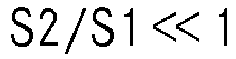
- the second effective liquid flow cross-section area S2 is smaller than the first effective liquid flow cross-section area S1, preferably by an order of magnitude (S2/S1 ⁇ 1) whereas the second maximum liquid flow cross-section area S2 is smaller than the entrance cross-section S3 (S2/S3 ⁇ 1).
- the speed vectors of a liquid flowing from said distribution chamber through the connection passage are all oriented in an axially symmetrical fashion and have the same absolute value. This results in a reduction of turbulences in the liquid, specifically within the third chamber into which it is flowing to. This leads to a laminar flow of the liquid within said third chamber which results in an increase of the working distance of the jet of liquid.
- a laser beam is being coupled into a jet of liquid.
- the jet of liquid thereby acts as light conductor to guide the laser beam onto a workpiece by means of total internal reflection, whereby the diameter of the laser beam remains constant over the entire working length of the jet of liquid.
- the laser beam is generated by an appropriate high power laser, such as a Nd:YAG laser.
- the laser beam is then directed by means of optical elements, such as lenses or mirrors into the jet of liquid.
- the "working distance" of a jet of liquid is the distance, within which the liquid remains in a coherent stream with a substantially constant diameter. After said working distance, the jet of liquid has the tendency to break down into drops.
- the distribution chamber has an annular shape, wherein the term "annulus” is used in the mathematical context, i.e. an annulus is a region bounded by two concentric circles.
- the distribution chamber has an extension in a third dimension such as to enclose a volume into which the liquid may flow.
- the circles defining the annular shape have centres which are identical with the jet axis.
- the extension in the third dimension of the distribution chamber is therefore oriented in a direction which is parallel to the jet axis. Said third dimension is referred to as "height" of the distribution chamber throughout this application.
- the radii of the two concentric circles are constant along the entire height of the distribution chamber.
- the distribution chamber would hence have the shape of a cylinder of rotation with a first diameter with a cut out cylinder of rotation with a second, smaller diameter.
- said distribution chamber may have other cross-sections in said plane, such as e.g. round, ellipsoid or polygonal, i.e. the radii of said two concentric circles vary over the height of the distribution chamber.
- the three-dimensional form of the distribution chamber would hence be toroidal.
- said liquid is water.
- first effective liquid flow cross-section area is a surface area lying within said distribution chamber and being a cross-section area of said distribution chamber and a surface of a body of revolution defined by a first vector rotated about the jet axis around 360°, wherein said first vector fulfils the following conditions:
- the flow direction vector through the at least one outlet of the distribution chamber indicates the flow direction of the liquid through said at least one outlet of the distribution chamber directly at the transition between the distribution chamber and the at least one outlet of the distribution chamber.
- said outlet will be arranged on a surface defining a wall of said distribution chamber.
- the flow direction vector indicates the flow direction of the liquid at the location where said outlet is arranged in said wall.
- the flow direction vector is taken as an average of the sum of all liquid flow vectors.
- said at least one outlet of the distribution chamber leads the liquid axially, i.e. parallel to the jet axis, out of said distribution chamber.
- said first vector is perpendicular to said jet axis.
- the magnitude of said first vector corresponds to the maximal dimension of the distribution chamber in a direction perpendicular to the jet axis and lying within the plane including said jet axis.
- the distribution chamber is of an annular shape being concentric with the jet axis in this embodiment, the magnitude of the first vector corresponds to the maximal difference between an outer radius and an inner radius of said annular distribution chamber.
- the rotation body of said first vector is an annulus.
- the first effective liquid flow cross-section area is equal to the base area of the hollow cylinder.
- the at least one outlet of the distribution chamber may be arranged at an angle relative to said jet axis.
- the rotation body is a frustum lying within said distribution chamber. The first effective liquid flow cross-section area is then equal to the surface of said frustum.
- all outlets of the distribution chamber are rotation symmetric to each other around the jet axis.
- the rotation body derived from the flow direction vector of the liquid flow through one of said outlets is equal to the rotation body derived from the flow direction vector of any other of the further outlets of the distribution chamber.
- the first effective liquid flow cross-section area may be determined on the basis of any one of the outlets of the distribution chamber.
- “Rotation symmetric” as understood herein is the arrangement of the outlets of the distribution chamber such that any two of said outlets are congruent to each other after a rotation about a partial turn around the jet axis.
- the outlets are arranged in a regular pattern, i.e. any outlet is congruent to its neighbouring outlets after a defined partial turn around the jet axis.
- the distribution chamber is shaped such that the maximal dimension in the direction of the first vector is as close as possible to the at least one outlet of the distribution chamber. This ensures a very effective reduction of turbulence in the acceleration chamber.
- said at least one outlet of the distribution chamber is configured as a single annular slot in a surface of said distribution chamber, said annular slot extending around 360° around the jet axis.
- the distribution chamber comprises a multitude of outlets in the form of circles or circle sectors, preferably half circles, which are arranged on the same surface of said distribution chamber.
- said multitude of outlets of the distribution chamber are all arranged in a circular way around said jet axis, preferably in a rotation symmetric way.
- each outlet of the multitude of outlets of the distribution chamber is spaced from neighbouring outlets by a defined distance, i.e. each outlet of the distribution chamber is arranged at a defined angle relative to the jet axis in relation to neighbouring outlets.
- the multitude of outlets of the distribution chamber may be arranged so closely together that their circumferences touch each other.
- the acceleration chamber preferably has a disc shape.
- the window is preferably arranged in one of the bases of the disc, while the at least one inlet of the acceleration chamber is arranged at a radial position of said disc shape, either on one of the bases of the disc shape or on a lateral surface thereof.
- the window is made of any suitable material which is transparent to the laser beam used and which is able to withstand the liquid pressure within said acceleration chamber.
- the at least one window is arranged such that the jet axis passes through said window, such that the laser beam may be lead into said acceleration chamber through said window along said jet axis.
- the acceleration chamber is preferably coaxial to the jet axis, i.e. a centre of a disc like acceleration chamber is located on said jet axis.
- said acceleration chamber is located at a different position along the jet axis as said distribution chamber, e.g. above or below said distribution chamber, if the jet axis is aligned to be vertical.
- vertical defines a direction in space which is parallel to the direction of earth gravity. This configuration allows saving lateral space, as both chambers are arranged on top of each other rather than next to each other.
- said distribution chamber and said acceleration chamber are coaxial to each other, i.e. the acceleration chamber is arranged within the centre of the annular shape of the distribution chamber.
- the acceleration chamber has an entrance cross-section S3 defined by a surface area of a cylinder barrel of a geometric cylinder arranged coaxially to the jet axis.
- the radius of the geometric cylinder equals the distance between the jet axis and the at least one inlet of the acceleration chamber, which is located closest to said jet axis in a plane including said jet axis.
- the cylinder barrel has a surface area which corresponds to 2 ⁇ rh, wherein r is the distance between the jet axis and the inlet of the acceleration chamber which is closest to said jet axis, and wherein h is the dimension of the acceleration chamber in a direction parallel to the jet axis, i.e. the height of the disc for a disc shaped acceleration chamber.
- the outlet of the acceleration chamber is located coaxial to said jet axis.
- said outlet is hence also coaxial with the centre of a base of the disc shape.
- the liquid flows into said acceleration chamber through said at least one inlet of the acceleration chamber and will flow to the outlet of said acceleration chamber.
- the velocity of said liquid flow will increase.
- the liquid is accelerated within the acceleration chamber towards the outlet.
- the acceleration chamber may have different shapes, a disc like shape is most preferred, as this yields the highest acceleration with the least disturbance of the liquid flow. Hence, a good acceleration performance may be linked to the necessary maintenance of a laminar flow of the liquid within the acceleration chamber.
- a disc shaped acceleration chamber includes one annular slot as inlet, said annular slot being arranged on either of the bases of the disc or on a lateral surface thereof.
- said at least one inlet of said acceleration chamber may be configured as a multiplicity of openings, preferably in the form of circles or circle sectors.
- the nozzle is arranged within the outlet of the acceleration chamber. Hence, liquid passing through said outlet will flow to said nozzle.
- the nozzle has a nozzle hole, which preferably is round in shape. The liquid may flow through said nozzle hole and exit said acceleration chamber. Said nozzle hole generates the jet of liquid and hence defines the orientation of the jet axis. Said nozzle hole is thereby smaller in diameter than said outlet of the acceleration chamber.
- connection passage is arranged between the at least one outlet of the distribution chamber and the at least one inlet of the acceleration chamber.
- the number of outlets of the distribution chamber matches the number of inlets of the acceleration chamber.
- a connection passage is arranged between each outlet of the distribution chamber and each inlet of the acceleration chamber.
- the second effective liquid flow cross-section area is the surface area of a plane intersecting said connection passage in a direction perpendicular to the flow direction of the liquid through said connection passage at a location where said cross-section perpendicular to the flow direction is minimal.
- the second effective liquid flow cross-section area is the smallest area perpendicular to the flow direction of the liquid within said connection passage. If the device comprises more than one connection passage, then said second effective liquid flow cross-section area is the sum of all cross-section areas perpendicular to the flow direction of the liquid through each connection passage at the respective location, where said section area is smallest for each connection passage.
- an "order of magnitude" is understood as factor of ten.
- the second effective liquid flow cross-section area is at least ten times smaller than the first effective liquid flow cross-section area. More preferably, said second effective liquid flow cross-section area is 20 times smaller than said first effective liquid flow cross-section area.
- the velocity vectors of the liquid within the connection passage satisfy the cylindrical symmetry and have the same norm value, which facilitates a laminar flow with reduced turbulence within the acceleration chamber.
- the second effective liquid flow cross-section area being smaller than the entrance cross-section, a laminar flow with almost no turbulence is achieved within said acceleration chamber. This then leads to an increase of the working distance of the jet of liquid compared with prior art nozzle arrangements.
- said distribution chamber and said acceleration chamber are arranged spaced from each other along the jet axis, while the at least one connecting channel is arranged parallel to said jet axis.
- the cross-section of the distribution chamber is thereby rectangular in a plane parallel to the jet axis and including said jet axis.
- the first effective liquid flow cross-section area is defined by an annulus having a normal which is parallel to the jet axis.
- the at least one connecting channel has a constant cross-section.
- the second effective liquid flow cross-section area is thereby equal to a section area of a plane having a normal parallel to said jet axis with said at least one connecting channel.
- connection passage is rotationally symmetric relative to the jet axis.
- connection passage consists of one annular duct which is coaxial to the jet axis.
- the distribution chamber comprises a single outlet in the form of an annular slot and said acceleration chamber comprises a single inlet in the form of an annular slot.
- said annular slot, said outlet of the distribution chamber and said inlet of the acceleration chamber have substantially the same radii and are aligned parallel to said jet axis.
- the acceleration chamber preferably has the shape of a circular cylinder having a radius that is greater than a height of the cylinder, wherein said height preferably is ⁇ 1 mm.
- the connection passage consists of at least two ducts having substantially the same shape and dimensions.
- the distribution chamber has one inlet.
- said at least one inlet of the distribution chamber for the liquid is arranged on a tangential position on a surface of said distribution chamber, wherein the liquid is injected through said at least one inlet of the distribution chamber into the distribution chamber in a direction generally towards said jet axis.
- the distribution chamber may comprise more than one inlet of the distribution chamber, such as two, three, four or more inlets of the distribution chamber.
- the at least one inlet of the distribution chamber is preferably coupled to a liquid supply which allows the supply of liquid with a defined liquid flow and/or a defined pressure into said distribution chamber.
- the window is preferably a transparent element forming at least a part of a wall of the acceleration chamber. This allows a simple overall configuration of the acceleration chamber.
- the device according to the present invention comprises one wall element having a central opening, wherein a nozzle holder comprising the nozzle and a window element comprising the window are arranged one above the other along said jet axis within said central opening, said nozzle holder and said window element being spaced from each other, said spacing defining the height of said acceleration chamber.
- connection passage is according to the present invention formed in said nozzle holder.
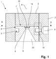
- Fig. 1 shows a cross-section through an embodiment of a device 1, according to the present invention, for generating a jet of liquid according to the present invention.
- the device 1 comprises a wall element 2 with a central opening. Within said central opening, a window element 3 and a nozzle holder 4 are arranged.
- the wall element 2 is in the shape of a full cylinder with a cut off of a full cylinder with a smaller radius. Accordingly, the window element 3 and the nozzle holder 4 are in the form of cylinders which may be affixed within the central opening of the wall element 2.
- the nozzle holder 4 comprises an outlet 18 of the acceleration chamber 7.
- a nozzle 8 is arranged within said outlet 18.
- the nozzle 8 comprises a nozzle hole 19 which creates a jet of liquid which propagates along a jet axis A.
- the jet axis A thereby marks the centre of the jet of liquid.
- the nozzle hole 19 has a round shape which yields a jet of liquid having a generally round cross-section.
- the window element 3 is made of a material which is transparent to laser radiation, such that a laser beam (not shown) may pass trough said window element 3 along the jet axis A.
- the laser beam is generated by a laser and guided towards said window element 3 and aligned to the jet axis A by means of optic elements as is known in the art.
- the device 1 further comprises a liquid supply connection 9 with which the device may be connected to a liquid supply unit, such as a pump, duct or the like.
- a liquid may be supplied to the device with a determined pressure and/or with a determined flow rate.
- the liquid supply connection is located in said wall element 2.
- the liquid supply connection 9 is in open communication with a distribution chamber 5.
- the distribution chamber 5 is in the form of an annulus extending around the jet axis A.
- the distribution chamber 5 has a rectangular cross-section in a plane including said jet axis A. In the figure, this plane corresponds to the plane of the paper.
- the distribution chamber 5 serves to distribute the liquid supplied to the device through the liquid supply connection 9 symmetrically around the jet axis A.
- the device 1 comprises an acceleration chamber 7 which is located between said window element 3 and said nozzle holder 4 including nozzle 8.
- the acceleration chamber 7 has a disc shape and extends around said jet axis A. Liquid flows from said distribution chamber 5 into said acceleration chamber 7 through a connecting channel 6, which in the embodiment shown is configured as annular slot extending around said jet axis A.
- the nozzle holder 4 comprises a conical opening 20 below said nozzle 8 in propagation direction of said jet of liquid. This conical opening 20 allows the jet of liquid to propagate without any device generated disturbance out of said device 1.
- the distribution chamber 5 as well as the connection passage 6 are formed within the nozzle holder 4.
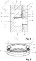
- Fig. 2 is a detailed view of a section of the device 1 according to Fig. 1 . Said section is marked in Fig. 1 by a rectangle with dashed lines.
- the liquid supply connection 9 abuts into the distribution chamber 5 by means of an inlet 10.
- said distribution chamber 5 has an outlet 11 which connects said distribution chamber 5 openly with the connection passage 6.
- Said connection passage 6 abuts into the acceleration chamber 7 by means of an inlet 12.
- the distribution chamber 5 has a first effective liquid flow cross-section area S1 which equals the surface of a rotation body 15 (see Fig. 3 ) defined by a first vector 14.
- Said first vector 14 is perpendicular to a flow direction vector 13 of the liquid through said outlet 11 of the distribution chamber 5 and spans in a plane comprising said jet axis A.
- the first vector has a magnitude which corresponds to a maximum dimension of the cross-section of the distribution chamber 5 in the direction of the first vector 14.
- the dimension used to define the magnitude of said first vector 14 is identical at any position within said plane.
- connection passage 6 has a second effective liquid flow cross-section area S2 which corresponds to the surface of intersection between a plane having a normal vector which is parallel to the flow direction vector 13 of the liquid within said connection passage 6 at a location where a cross-section of said connecting channel 6 within said plane is minimal and said connecting channel 6.
- the second effective liquid flow cross-section area S2 corresponds to the smallest area perpendicular to the flow direction of the liquid within said connection passage 6.
- the acceleration chamber 7 has an effective entry cross-section S3 defined by a surface area of a cylinder barrel 17 of a geometric cylinder arranged coaxially to the jet axis A.
- the cylinder barrel 17 has a radius r corresponding to the smallest distance between the jet axis A and the inlet 12 of the acceleration chamber 7, said area of the cylinder barrel being located within said acceleration chamber 7.
- a schematic representation of said cylinder barrel 17 is shown in Fig. 10 .
- Fig. 3 is a three dimensional schematic representation of the first effective liquid flow cross-section area S1 of the embodiment of the device as shown in Fig. 1 .
- the annular shape of the distribution chamber 5 may be clearly seen.
- the outlet 11 of the distribution chamber is in the shape of an annular slot located about an outer radius of said annular distribution chamber 5.
- the flow direction vector 13 through said outlet 11 of the distribution chamber 5 is parallel to the jet axis A.
- the first vector 14 lies perpendicular to said flow direction vector 13 within a plane F which includes said jet axis A.
- the magnitude of the first vector 14 corresponds to the maximum dimension of the distribution chamber 15 within said plane F.
- the first effective liquid flow cross-section area S1 is obtained by the surface area of a rotation body 15 generated by a full rotation said first vector 14 around the jet axis A.
- the rotation body 15 is an annulus which has the same surface area as a base surface of distribution chamber 5.
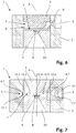
- Fig. 4 is a detailed view of an alternative embodiment of a device 1 according to the present invention.
- the cross-section of the distribution chamber 5 has a polygonal shape in a cross-section lying in plane F.
- the magnitude of the first vector 14 equals the maximum dimension of the distribution chamber 5 in said plane in the direction of said first vector 14.
- the resulting rotation body 15 will be an annulus as in the embodiment shown in Fig. 3 .
- Fig. 5 shows a cross-section of a device 1. It is generally identical with the embodiment as shown in Fig. 1 , with the exception of the arrangement of the distribution chamber 5 in the wall element 2. As the connection passage 6 is arranged in said nozzle holder 4, the distribution chamber 5 also extends into the nozzle holder 4, at least to an extent which corresponds to the diameter of the connection passage 6.
- Fig. 6 shows yet another device 1.
- both the distribution chamber 5 and the connection passage 6 are arranged in said window element 3.
- Fig. 7 shows another device 1.
- a multitude of connection passages 6.1 - 6.7 (of which only two connection passages 6.1, 6.7 are shown for perspective reasons) are arranged between said distribution chamber 5 and said acceleration chamber 7. Consequently, the acceleration chamber 7 has a multitude of inlets 12.1 - 12.7.
- the connection passages 6.1 - 6.7 are arranged in a spoke-like configuration between said distribution chamber 5 and said acceleration chamber 7.
- the distribution chamber 5, the connection passages 6.1 - 6.7 and the acceleration chamber 7 are generally all arranged in the same level about the jet axis A. This has an influence on the orientation of the first effective liquid flow cross-section area S1, as is explained in more detail in connection with Figs. 8 and 9 .
- the second effective cross section area S2 is the sum of all cross-section areas 16 perpendicular to the flow direction of the liquid through each connection passage 6.1 - 6.7 at the respective location, where said section area is smallest for each connection passage 6.1 - 6.7.
- Fig. 8 shows a detailed view of a section of the device 1 according to Fig. 7 .
- Said section is marked in Fig. 7 by a rectangle with dashed lines.
- the flow direction vector 13 through the outlets 11.1 - 11.7 of the distribution chamber 5 lies on the plane F and is perpendicular to the jet axis A.
- the situation is shown for one outlet 11.7.
- the first vector 14 is parallel to said jet axis A.
- the resulting rotation body 15 is not an annulus like the rotation body 15 obtained for the embodiment as shown in Fig. 1 , but the rotation body 15 is a cylinder barrel.
- the height of the cylinder and its radius are determined by the maximum dimension of the cross-section of the distribution chamber 5 in the direction of the first vector 14 in the plane F and by the radial position of the first vector 14, respectively.
- the distribution chamber 5 has a rectangular cross-section in said plane F, i.e. the dimension of the distribution chamber 5 in the direction of the first vector 14 is constant along the entire plane.
- the rotation body 15 is generated with a rotation radius which equals the minimal radius between the jet axis A and the first vector 14.
- the flow direction vector 13 is perpendicular to the outlet 11.1 - 11.6 of the distribution chamber 5 pointing towards said jet axis A and the first vector 14 accordingly arranged parallel to the jet axis A.
- the surface area of the rotation body 15 which equals the first effective liquid flow cross-section area S1 is highlighted with stripes in this figure.
- Fig. 10 shows a schematic three-dimensional representation of the entrance cross-section S3 of the acceleration chamber 7 which is identical to and is defined by the cylinder barrel 17.
- the cylinder barrel 17 is arranged within said acceleration chamber 7 coaxial to said jet axis A.
- the radius r of said cylinder barrel is defined by the minimal distance between said jet axis A and the inlet 12 of said acceleration chamber 7.
- the inlet 12 of the acceleration chamber 7 is configured as an annular slot.
- the minimal distance between the inlet 12 of the acceleration chamber 7 and the jet axis A equals to the inner radius of said annular slot.
- the surface area of the cylinder barrel 17 and hence the entrance cross-section S3 may be calculated as 2 ⁇ rh, where h is the height of the acceleration chamber, i.e. its dimension along the jet axis A.
- Fig. 11 is a cross-section of an embodiment of the device 1 as shown in Fig. 1 in a plane B-B perpendicular to said jet axis A.
- the second cross section area S2 or the connection passage 6 have an annular shape.
- the arrangement of the nozzle 8 and the outlet 18 of the acceleration chamber 7 may be recognized. Note that the nozzle 8 has a nozzle hole 19 coaxial with said jet axis A.
- Figs. 12 and 13 show alternative embodiments of an inventive device 1 having multiple connection passages 6 and hence multiple inlets 12 (not shown in Figs. 12 and 13 ).
- the connection passages 6 have a semi-circular shape.
- the connection passages 6 have a circular shape.
Landscapes
- Engineering & Computer Science (AREA)
- Physics & Mathematics (AREA)
- Optics & Photonics (AREA)
- Plasma & Fusion (AREA)
- Mechanical Engineering (AREA)
- Nozzles (AREA)
- Surgical Instruments (AREA)
- Laser Beam Processing (AREA)
Description
- The invention relates to a device for generating a jet of liquid propagating along a jet axis, said jet of liquid guiding a laser
beam, according to the preamble of claim 1 (see, for example,US 2012/152919 A1 ). - Material machining using laser radiation is used in a very wide variety of ways for cutting, drilling, milling, welding, marking and generally for removing material. To make it possible to commence removal of material, a predetermined intensity of the radiation has to be reached on the material surface which is to be machined. This high radiation intensity used to be achieved by focusing the laser radiation at the focal point. However, a drawback of this technique is the small axial extent of the focal point (beam width) in which this high intensity was reached. This axial extent is linked to the Rayleigh length. If deep cuts or holes are to be made, the location of the focal point has to be adapted with a high level of accuracy or even tracked. The beam tapers conically toward the focal point, meaning that particularly in the case of deep cuts, starting on the surface it was always necessary to remove sufficient amounts of material for the conical beam to be able to reach the machining location. However, deep cuts or holes always have to be made with inclined side walls.
- To avoid having to track the focal point and to be able to make narrow cuts and holes with approximately vertical side walls, it has been proposed in
EP A 0 515 983 ,DE A 36 43 284 andWO 95/32834 - In
DE A 36 43 284 , the laser radiation was supplied by means of a glass fiber. The end of this glass fiber had a water jet which was directed onto the workpiece to be machined flowing around it. The known device had the drawback that the diameter of the water jet was never allowed to be smaller than that of the glass fiber carrying the laser radiation. A further drawback resulted from a region of dead water beneath the end of the glass fiber, causing, among other things, disturbances in the water jet flow and ultimately leading to this jet rapidly breaking down into drops. -
EP A 0 515 983 has attempted to avoid these drawbacks by designing an optics unit with a nozzle block which shapes the water jet. Upstream of the nozzle which shapes the water jet was a water retention chamber having a water inlet and a focusing lens, which closes off the chamber from the nozzle entry, for focusing the laser radiation. The location and focal length of the focusing lens were selected in such a manner that the focal point of the laser radiation was located in the axial center inside the nozzle channel. In operation during machining, it has been found that the nozzle was very quickly damaged by the laser radiation, and consequently the shaping of the radiation was no longer perfect. - An improvement to the way in which the laser beam is injected into the liquid jet was made in
WO 95/32834 -
WO 99/56907 - It is the object of the invention to create a device pertaining to the technical field initially mentioned, that allows increasing the working distance of the jet of liquid, i.e. the distance within which the liquid remains in a coherent stream with a substantially constant diameter.
- A device according to the present invention is defined in
claim 1. According to the invention the device for generating a jet of liquid propagating along a jet axis, said jet of liquid guiding a laser beam, comprises a distribution chamber with at least one inlet and at least one outlet for the liquid. Said distribution chamber is of an annular shape encircling said jet axis and has a first effective liquid flow cross-section area S1. Further, the device comprises an acceleration chamber having at least one inlet and one outlet for the liquid as well as a window transparent to said laser beam to introduce said laser beam into said acceleration chamber through said window. The window is arranged in line with the jet axis to enable the introduction of the laser beam coaxial to said jet axis. The acceleration chamber has an entrance cross-section defined by a surface area of a cylinder barrel of a geometric cylinder arranged coaxially to the jet axis. The barrel has a radius r corresponding to the smallest distance between the jet axis and said at least one inlet of the acceleration chamber, wherein said area of the cylinder barrel being located within said acceleration chamber. A nozzle with a nozzle hole generating said jet of liquid is arranged in said outlet of the acceleration chamber. Said nozzle hole defines a direction of the jet axis. Additionally, a connection passage extends from the at least one outlet of the distribution chamber to the at least one inlet of the acceleration chamber, wherein said connection passage has a second effective liquid flow passage cross-section area S2. The second effective liquid flow cross-section area S2 is smaller than the first effective liquid flow cross-section area S1, preferably by an order of magnitude (S2/S1 << 1) whereas the second maximum liquid flow cross-section area S2 is smaller than the entrance cross-section S3 (S2/S3 < 1). - By providing a second effective liquid flow cross-section area which is smaller than the first effective liquid flow cross-section area, the speed vectors of a liquid flowing from said distribution chamber through the connection passage are all oriented in an axially symmetrical fashion and have the same absolute value. This results in a reduction of turbulences in the liquid, specifically within the third chamber into which it is flowing to. This leads to a laminar flow of the liquid within said third chamber which results in an increase of the working distance of the jet of liquid.
- With the device according to the present invention, a laser beam is being coupled into a jet of liquid. The jet of liquid thereby acts as light conductor to guide the laser beam onto a workpiece by means of total internal reflection, whereby the diameter of the laser beam remains constant over the entire working length of the jet of liquid. This allows the cutting of materials, like metals, ceramics or semiconductors with a well-defined and constant diameter. The laser beam is generated by an appropriate high power laser, such as a Nd:YAG laser. The laser beam is then directed by means of optical elements, such as lenses or mirrors into the jet of liquid.
- In the following application, the "working distance" of a jet of liquid is the distance, within which the liquid remains in a coherent stream with a substantially constant diameter. After said working distance, the jet of liquid has the tendency to break down into drops.
- The distribution chamber has an annular shape, wherein the term "annulus" is used in the mathematical context, i.e. an annulus is a region bounded by two concentric circles. Further, the distribution chamber has an extension in a third dimension such as to enclose a volume into which the liquid may flow. As the distribution chamber is coaxial with the jet axis, the circles defining the annular shape have centres which are identical with the jet axis. The extension in the third dimension of the distribution chamber is therefore oriented in a direction which is parallel to the jet axis. Said third dimension is referred to as "height" of the distribution chamber throughout this application.
- Preferably, the radii of the two concentric circles are constant along the entire height of the distribution chamber. This leads to a rectangular cross-section of the distribution chamber in a plane which has a normal vector perpendicular to the jet axis and within which said jet axis is lying. In three dimensions, the distribution chamber would hence have the shape of a cylinder of rotation with a first diameter with a cut out cylinder of rotation with a second, smaller diameter.
- Alternatively, said distribution chamber may have other cross-sections in said plane, such as e.g. round, ellipsoid or polygonal, i.e. the radii of said two concentric circles vary over the height of the distribution chamber. In the case of a round or ellipsoid cross-section, the three-dimensional form of the distribution chamber would hence be toroidal.
- Preferably said liquid is water.
- In the present application the "first effective liquid flow cross-section area" is a surface area lying within said distribution chamber and being a cross-section area of said distribution chamber and a surface of a body of revolution defined by a first vector rotated about the jet axis around 360°, wherein said first vector fulfils the following conditions:
- the first vector is perpendicular to a flow direction vector of the liquid flow through said at least one outlet of the distribution chamber;
- the first vector lies in a plane which includes said jet axis;
- said first vector has a magnitude which corresponds to a maximum dimension of the cross-section of the distribution chamber in the direction of the first vector within said plane which includes said jet axis.
- The flow direction vector through the at least one outlet of the distribution chamber indicates the flow direction of the liquid through said at least one outlet of the distribution chamber directly at the transition between the distribution chamber and the at least one outlet of the distribution chamber. Usually, said outlet will be arranged on a surface defining a wall of said distribution chamber. Hence, the flow direction vector indicates the flow direction of the liquid at the location where said outlet is arranged in said wall. In the case that the flow of liquid through said at least one outlet of the distribution chamber comprises multiple liquid flow vectors, e.g. because the at least one outlet of the distribution chamber has rounded edges, the flow direction vector is taken as an average of the sum of all liquid flow vectors.
- In a preferred embodiment, said at least one outlet of the distribution chamber leads the liquid axially, i.e. parallel to the jet axis, out of said distribution chamber. As the flow direction vector is parallel to the jet axis, said first vector is perpendicular to said jet axis. The magnitude of said first vector corresponds to the maximal dimension of the distribution chamber in a direction perpendicular to the jet axis and lying within the plane including said jet axis. As the distribution chamber is of an annular shape being concentric with the jet axis in this embodiment, the magnitude of the first vector corresponds to the maximal difference between an outer radius and an inner radius of said annular distribution chamber. The rotation body of said first vector is an annulus.
- In the case that the distribution chamber is in the form of a hollow cylinder, i.e. the radii of the annulus are constant over the height of the distribution chamber, the first effective liquid flow cross-section area is equal to the base area of the hollow cylinder.
- In a further embodiment, the at least one outlet of the distribution chamber may be arranged at an angle relative to said jet axis. In this case, the rotation body is a frustum lying within said distribution chamber. The first effective liquid flow cross-section area is then equal to the surface of said frustum.
- Preferably, all outlets of the distribution chamber are rotation symmetric to each other around the jet axis. In this case, the rotation body derived from the flow direction vector of the liquid flow through one of said outlets is equal to the rotation body derived from the flow direction vector of any other of the further outlets of the distribution chamber. Hence, the first effective liquid flow cross-section area may be determined on the basis of any one of the outlets of the distribution chamber.
- "Rotation symmetric" as understood herein is the arrangement of the outlets of the distribution chamber such that any two of said outlets are congruent to each other after a rotation about a partial turn around the jet axis. Preferably, the outlets are arranged in a regular pattern, i.e. any outlet is congruent to its neighbouring outlets after a defined partial turn around the jet axis.
- Preferably, the distribution chamber is shaped such that the maximal dimension in the direction of the first vector is as close as possible to the at least one outlet of the distribution chamber. This ensures a very effective reduction of turbulence in the acceleration chamber.
- In a preferred embodiment, said at least one outlet of the distribution chamber is configured as a single annular slot in a surface of said distribution chamber, said annular slot extending around 360° around the jet axis. In an alternative embodiment, the distribution chamber comprises a multitude of outlets in the form of circles or circle sectors, preferably half circles, which are arranged on the same surface of said distribution chamber. Preferably, said multitude of outlets of the distribution chamber are all arranged in a circular way around said jet axis, preferably in a rotation symmetric way. Preferably, each outlet of the multitude of outlets of the distribution chamber is spaced from neighbouring outlets by a defined distance, i.e. each outlet of the distribution chamber is arranged at a defined angle relative to the jet axis in relation to neighbouring outlets. In one embodiment, the multitude of outlets of the distribution chamber may be arranged so closely together that their circumferences touch each other.
- The acceleration chamber preferably has a disc shape. The window is preferably arranged in one of the bases of the disc, while the at least one inlet of the acceleration chamber is arranged at a radial position of said disc shape, either on one of the bases of the disc shape or on a lateral surface thereof. The window is made of any suitable material which is transparent to the laser beam used and which is able to withstand the liquid pressure within said acceleration chamber. The at least one window is arranged such that the jet axis passes through said window, such that the laser beam may be lead into said acceleration chamber through said window along said jet axis.
- The acceleration chamber is preferably coaxial to the jet axis, i.e. a centre of a disc like acceleration chamber is located on said jet axis.
- Preferably, said acceleration chamber is located at a different position along the jet axis as said distribution chamber, e.g. above or below said distribution chamber, if the jet axis is aligned to be vertical. In the present application, the term "vertical" defines a direction in space which is parallel to the direction of earth gravity. This configuration allows saving lateral space, as both chambers are arranged on top of each other rather than next to each other.
- Alternatively, said distribution chamber and said acceleration chamber are coaxial to each other, i.e. the acceleration chamber is arranged within the centre of the annular shape of the distribution chamber.
- The acceleration chamber has an entrance cross-section S3 defined by a surface area of a cylinder barrel of a geometric cylinder arranged coaxially to the jet axis. The radius of the geometric cylinder equals the distance between the jet axis and the at least one inlet of the acceleration chamber, which is located closest to said jet axis in a plane including said jet axis. In principle, the cylinder barrel has a surface area which corresponds to 2πrh, wherein r is the distance between the jet axis and the inlet of the acceleration chamber which is closest to said jet axis, and wherein h is the dimension of the acceleration chamber in a direction parallel to the jet axis, i.e. the height of the disc for a disc shaped acceleration chamber.
- The outlet of the acceleration chamber is located coaxial to said jet axis. In the case of a disc shaped acceleration chamber, said outlet is hence also coaxial with the centre of a base of the disc shape.
- The liquid flows into said acceleration chamber through said at least one inlet of the acceleration chamber and will flow to the outlet of said acceleration chamber. As the volume available for the liquid flow decreases towards the outlet in function of the decreasing distance to the jet axis, the velocity of said liquid flow will increase. Hence, the liquid is accelerated within the acceleration chamber towards the outlet.
- While the acceleration chamber may have different shapes, a disc like shape is most preferred, as this yields the highest acceleration with the least disturbance of the liquid flow. Hence, a good acceleration performance may be linked to the necessary maintenance of a laminar flow of the liquid within the acceleration chamber.
- Preferably, a disc shaped acceleration chamber includes one annular slot as inlet, said annular slot being arranged on either of the bases of the disc or on a lateral surface thereof. Alternatively, said at least one inlet of said acceleration chamber may be configured as a multiplicity of openings, preferably in the form of circles or circle sectors.
- The nozzle is arranged within the outlet of the acceleration chamber. Hence, liquid passing through said outlet will flow to said nozzle. The nozzle has a nozzle hole, which preferably is round in shape. The liquid may flow through said nozzle hole and exit said acceleration chamber. Said nozzle hole generates the jet of liquid and hence defines the orientation of the jet axis. Said nozzle hole is thereby smaller in diameter than said outlet of the acceleration chamber.
- Between the at least one outlet of the distribution chamber and the at least one inlet of the acceleration chamber a connection passage is arranged. Preferably, the number of outlets of the distribution chamber matches the number of inlets of the acceleration chamber. In this case, a connection passage is arranged between each outlet of the distribution chamber and each inlet of the acceleration chamber.
- The second effective liquid flow cross-section area is the surface area of a plane intersecting said connection passage in a direction perpendicular to the flow direction of the liquid through said connection passage at a location where said cross-section perpendicular to the flow direction is minimal. Hence, the second effective liquid flow cross-section area is the smallest area perpendicular to the flow direction of the liquid within said connection passage. If the device comprises more than one connection passage, then said second effective liquid flow cross-section area is the sum of all cross-section areas perpendicular to the flow direction of the liquid through each connection passage at the respective location, where said section area is smallest for each connection passage.
- In the following application, an "order of magnitude" is understood as factor of ten. For example, in a preferred embodiment, the second effective liquid flow cross-section area is at least ten times smaller than the first effective liquid flow cross-section area. More preferably, said second effective liquid flow cross-section area is 20 times smaller than said first effective liquid flow cross-section area.
- With the selection of the second effective liquid flow cross-section area smaller than the first effective liquid flow cross-section area, especially by an order of magnitude, the velocity vectors of the liquid within the connection passage satisfy the cylindrical symmetry and have the same norm value, which facilitates a laminar flow with reduced turbulence within the acceleration chamber. With the second effective liquid flow cross-section area being smaller than the entrance cross-section, a laminar flow with almost no turbulence is achieved within said acceleration chamber. This then leads to an increase of the working distance of the jet of liquid compared with prior art nozzle arrangements.
- In a specially preferred embodiment, said distribution chamber and said acceleration chamber are arranged spaced from each other along the jet axis, while the at least one connecting channel is arranged parallel to said jet axis. The cross-section of the distribution chamber is thereby rectangular in a plane parallel to the jet axis and including said jet axis. In this configuration, the first effective liquid flow cross-section area is defined by an annulus having a normal which is parallel to the jet axis. Preferably, the at least one connecting channel has a constant cross-section. The second effective liquid flow cross-section area is thereby equal to a section area of a plane having a normal parallel to said jet axis with said at least one connecting channel.
- Preferably, the connection passage is rotationally symmetric relative to the jet axis.
- Preferably, the connection passage consists of one annular duct which is coaxial to the jet axis. In this case, the distribution chamber comprises a single outlet in the form of an annular slot and said acceleration chamber comprises a single inlet in the form of an annular slot. Preferably, said annular slot, said outlet of the distribution chamber and said inlet of the acceleration chamber have substantially the same radii and are aligned parallel to said jet axis.
- The acceleration chamber preferably has the shape of a circular cylinder having a radius that is greater than a height of the cylinder, wherein said height preferably is < 1 mm. Such a configuration of the acceleration chamber ensures a maximal acceleration of the liquid towards the outlet of said acceleration chamber and hence towards the nozzle. Alternatively, the connection passage consists of at least two ducts having substantially the same shape and dimensions. By providing ducts with substantially the same shape and dimension it is ensured that the velocity vectors of the liquid passing through said at least two ducts have the same norm value. This reduces the occurrence of turbulence within the acceleration chamber, as the liquid flowing into the acceleration chamber will have a uniform velocity.
- Preferably, the distribution chamber has one inlet. Preferably, said at least one inlet of the distribution chamber for the liquid is arranged on a tangential position on a surface of said distribution chamber, wherein the liquid is injected through said at least one inlet of the distribution chamber into the distribution chamber in a direction generally towards said jet axis.
- Alternatively, the distribution chamber may comprise more than one inlet of the distribution chamber, such as two, three, four or more inlets of the distribution chamber. The at least one inlet of the distribution chamber is preferably coupled to a liquid supply which allows the supply of liquid with a defined liquid flow and/or a defined pressure into said distribution chamber.
- However, provision of only one inlet of the distribution chamber reduces the complexity of the device, as only one liquid supply or connection tube to a liquid supply needs to be connected with the distribution chamber.
- The window is preferably a transparent element forming at least a part of a wall of the acceleration chamber. This allows a simple overall configuration of the acceleration chamber.
- The device according to the present invention comprises one wall element having a central opening, wherein a nozzle holder comprising the nozzle and a window element comprising the window are arranged one above the other along said jet axis within said central opening, said nozzle holder and said window element being spaced from each other, said spacing defining the height of said acceleration chamber.
- This allows providing the device in only three parts which may easily and quickly be assembled and disassembled, thus facilitating cleaning and maintenance operation on the device as well as replacement of parts.
- The connection passage is
according to the present invention formed in said nozzle holder. - Other advantageous embodiments and combinations of features come out from the detailed description below and the totality of the claims.
- The drawings used to explain the embodiments show:
- Fig. 1
- A cross-section through an embodiment of a device according to the present invention;
- Fig. 2
- a detailed view of a section of the device shown in
Fig. 1 ; - Fig. 3
- a three-dimensional schematic representation of the first effective liquid flow cross-section area of the embodiment according to
Fig. 1 ; - Fig. 4
- a detailed view of a cross-section of an alternative embodiment of an inventive device;
- Fig. 5
- a cross-section of another device;
- Fig. 6
- a cross-section of another device;
- Fig. 7
- a cross-section of another device having a multitude of connection passages;
- Fig. 8
- a detailed view of a section of the device shown in
Fig. 7 ; - Fig. 9
- a three-dimensional schematic representation of the first effective liquid flow cross-section area of the embodiment according to
Fig. 7 ; - Fig. 10
- a three-dimensional schematic representation of the entrance cross-section area S3 of the acceleration chamber;
- Fig. 11
- a cross-section B-B of an embodiment of the device as shown in
Fig. 1 in a plane perpendicular to said jet axis with a single connection passage; - Fig. 12
- a cross-section of an alternative embodiment of the device in a plane perpendicular to said jet axis with a multitude of semi-circular connection passages;
- Fig. 13
- a cross-section of an alternative embodiment of the device in a plane perpendicular to said jet axis with a multitude of circular connection passages.
- In the figures, the same components are denoted by the same reference symbols.
-
Fig. 1 shows a cross-section through an embodiment of adevice 1, according to the present invention, for generating a jet of liquid according to the present invention. Thedevice 1 comprises awall element 2 with a central opening. Within said central opening, awindow element 3 and anozzle holder 4 are arranged. In the embodiment shown, thewall element 2 is in the shape of a full cylinder with a cut off of a full cylinder with a smaller radius. Accordingly, thewindow element 3 and thenozzle holder 4 are in the form of cylinders which may be affixed within the central opening of thewall element 2. - The
nozzle holder 4 comprises anoutlet 18 of theacceleration chamber 7. Anozzle 8 is arranged within saidoutlet 18. Thenozzle 8 comprises anozzle hole 19 which creates a jet of liquid which propagates along a jet axis A. The jet axis A thereby marks the centre of the jet of liquid. Note that thenozzle hole 19 has a round shape which yields a jet of liquid having a generally round cross-section. Thewindow element 3 is made of a material which is transparent to laser radiation, such that a laser beam (not shown) may pass trough saidwindow element 3 along the jet axis A. The laser beam is generated by a laser and guided towards saidwindow element 3 and aligned to the jet axis A by means of optic elements as is known in the art. - The
device 1 further comprises aliquid supply connection 9 with which the device may be connected to a liquid supply unit, such as a pump, duct or the like. By means of said liquid supply connection 9 a liquid may be supplied to the device with a determined pressure and/or with a determined flow rate. In the embodiment shown, the liquid supply connection is located in saidwall element 2. - The
liquid supply connection 9 is in open communication with adistribution chamber 5. Thedistribution chamber 5 is in the form of an annulus extending around the jet axis A. In the embodiment shown, thedistribution chamber 5 has a rectangular cross-section in a plane including said jet axis A. In the figure, this plane corresponds to the plane of the paper. Thedistribution chamber 5 serves to distribute the liquid supplied to the device through theliquid supply connection 9 symmetrically around the jet axis A. - Further, the
device 1 comprises anacceleration chamber 7 which is located between saidwindow element 3 and saidnozzle holder 4 includingnozzle 8. Theacceleration chamber 7 has a disc shape and extends around said jet axis A. Liquid flows from saiddistribution chamber 5 into saidacceleration chamber 7 through a connectingchannel 6, which in the embodiment shown is configured as annular slot extending around said jet axis A. - Further, the
nozzle holder 4 comprises aconical opening 20 below saidnozzle 8 in propagation direction of said jet of liquid. Thisconical opening 20 allows the jet of liquid to propagate without any device generated disturbance out of saiddevice 1. - According to the present invention, the
distribution chamber 5 as well as theconnection passage 6 are formed within thenozzle holder 4. -
Fig. 2 is a detailed view of a section of thedevice 1 according toFig. 1 . Said section is marked inFig. 1 by a rectangle with dashed lines. In this detailed view, it may be seen that theliquid supply connection 9 abuts into thedistribution chamber 5 by means of aninlet 10. Further, saiddistribution chamber 5 has anoutlet 11 which connects saiddistribution chamber 5 openly with theconnection passage 6. Saidconnection passage 6 abuts into theacceleration chamber 7 by means of aninlet 12. - The
distribution chamber 5 has a first effective liquid flow cross-section area S1 which equals the surface of a rotation body 15 (seeFig. 3 ) defined by afirst vector 14. Saidfirst vector 14 is perpendicular to aflow direction vector 13 of the liquid through saidoutlet 11 of thedistribution chamber 5 and spans in a plane comprising said jet axis A. The first vector has a magnitude which corresponds to a maximum dimension of the cross-section of thedistribution chamber 5 in the direction of thefirst vector 14. As thedistribution chamber 5 has a rectangular cross-section in the plane defining the orientation of saidfirst vector 14, the dimension used to define the magnitude of saidfirst vector 14 is identical at any position within said plane. - The
connection passage 6 has a second effective liquid flow cross-section area S2 which corresponds to the surface of intersection between a plane having a normal vector which is parallel to theflow direction vector 13 of the liquid within saidconnection passage 6 at a location where a cross-section of said connectingchannel 6 within said plane is minimal and said connectingchannel 6. I.e. the second effective liquid flow cross-section area S2 corresponds to the smallest area perpendicular to the flow direction of the liquid within saidconnection passage 6. - The
acceleration chamber 7 has an effective entry cross-section S3 defined by a surface area of acylinder barrel 17 of a geometric cylinder arranged coaxially to the jet axis A. Thecylinder barrel 17 has a radius r corresponding to the smallest distance between the jet axis A and theinlet 12 of theacceleration chamber 7, said area of the cylinder barrel being located within saidacceleration chamber 7. A schematic representation of saidcylinder barrel 17 is shown inFig. 10 . -
Fig. 3 is a three dimensional schematic representation of the first effective liquid flow cross-section area S1 of the embodiment of the device as shown inFig. 1 . In this figure, the annular shape of thedistribution chamber 5 may be clearly seen. Theoutlet 11 of the distribution chamber is in the shape of an annular slot located about an outer radius of saidannular distribution chamber 5. In this embodiment, theflow direction vector 13 through saidoutlet 11 of thedistribution chamber 5 is parallel to the jet axis A. Thefirst vector 14 lies perpendicular to saidflow direction vector 13 within a plane F which includes said jet axis A. The magnitude of thefirst vector 14 corresponds to the maximum dimension of thedistribution chamber 15 within said plane F. The first effective liquid flow cross-section area S1 is obtained by the surface area of arotation body 15 generated by a full rotation saidfirst vector 14 around the jet axis A. In the embodiment shown, therotation body 15 is an annulus which has the same surface area as a base surface ofdistribution chamber 5. -
Fig. 4 is a detailed view of an alternative embodiment of adevice 1 according to the present invention. Compared to the embodiment as shown inFig. 1 , the cross-section of thedistribution chamber 5 has a polygonal shape in a cross-section lying in plane F. As is shown inFig. 4 , the magnitude of thefirst vector 14 equals the maximum dimension of thedistribution chamber 5 in said plane in the direction of saidfirst vector 14. As theflow direction vector 13 is parallel to the jet axis A, the resultingrotation body 15 will be an annulus as in the embodiment shown inFig. 3 . -
Fig. 5 shows a cross-section of adevice 1. It is generally identical with the embodiment as shown inFig. 1 , with the exception of the arrangement of thedistribution chamber 5 in thewall element 2. As theconnection passage 6 is arranged in saidnozzle holder 4, thedistribution chamber 5 also extends into thenozzle holder 4, at least to an extent which corresponds to the diameter of theconnection passage 6. -
Fig. 6 shows yet anotherdevice 1. In this device, both thedistribution chamber 5 and theconnection passage 6 are arranged in saidwindow element 3. -
Fig. 7 shows anotherdevice 1. In this device, a multitude of connection passages 6.1 - 6.7 (of which only two connection passages 6.1, 6.7 are shown for perspective reasons) are arranged between saiddistribution chamber 5 and saidacceleration chamber 7. Consequently, theacceleration chamber 7 has a multitude of inlets 12.1 - 12.7. In essence, the connection passages 6.1 - 6.7 are arranged in a spoke-like configuration between saiddistribution chamber 5 and saidacceleration chamber 7. Thedistribution chamber 5, the connection passages 6.1 - 6.7 and theacceleration chamber 7 are generally all arranged in the same level about the jet axis A. This has an influence on the orientation of the first effective liquid flow cross-section area S1, as is explained in more detail in connection withFigs. 8 and 9 . Further, it has to be noted that in this embodiment the second effective cross section area S2 is the sum of allcross-section areas 16 perpendicular to the flow direction of the liquid through each connection passage 6.1 - 6.7 at the respective location, where said section area is smallest for each connection passage 6.1 - 6.7. -
Fig. 8 shows a detailed view of a section of thedevice 1 according toFig. 7 . Said section is marked inFig. 7 by a rectangle with dashed lines. Compared to the embodiment as shown inFig. 1 , theflow direction vector 13 through the outlets 11.1 - 11.7 of thedistribution chamber 5 lies on the plane F and is perpendicular to the jet axis A. As example, the situation is shown for one outlet 11.7. As theflow direction vector 13 is perpendicular to the jet axis A, thefirst vector 14 is parallel to said jet axis A. - As shown in
Fig. 9 , the resultingrotation body 15 is not an annulus like therotation body 15 obtained for the embodiment as shown inFig. 1 , but therotation body 15 is a cylinder barrel. The height of the cylinder and its radius are determined by the maximum dimension of the cross-section of thedistribution chamber 5 in the direction of thefirst vector 14 in the plane F and by the radial position of thefirst vector 14, respectively. In the embodiment shown, thedistribution chamber 5 has a rectangular cross-section in said plane F, i.e. the dimension of thedistribution chamber 5 in the direction of thefirst vector 14 is constant along the entire plane. In this case, therotation body 15 is generated with a rotation radius which equals the minimal radius between the jet axis A and thefirst vector 14. - On
Fig. 9 , theflow direction vector 13 is perpendicular to the outlet 11.1 - 11.6 of thedistribution chamber 5 pointing towards said jet axis A and thefirst vector 14 accordingly arranged parallel to the jet axis A. The surface area of therotation body 15 which equals the first effective liquid flow cross-section area S1 is highlighted with stripes in this figure. -
Fig. 10 shows a schematic three-dimensional representation of the entrance cross-section S3 of theacceleration chamber 7 which is identical to and is defined by thecylinder barrel 17. Thecylinder barrel 17 is arranged within saidacceleration chamber 7 coaxial to said jet axis A. The radius r of said cylinder barrel is defined by the minimal distance between said jet axis A and theinlet 12 of saidacceleration chamber 7. In the embodiment shown, theinlet 12 of theacceleration chamber 7 is configured as an annular slot. Hence, the minimal distance between theinlet 12 of theacceleration chamber 7 and the jet axis A equals to the inner radius of said annular slot. The surface area of thecylinder barrel 17 and hence the entrance cross-section S3 may be calculated as 2πrh, where h is the height of the acceleration chamber, i.e. its dimension along the jet axis A. -
Fig. 11 is a cross-section of an embodiment of thedevice 1 as shown inFig. 1 in a plane B-B perpendicular to said jet axis A. As may be seen, the second cross section area S2 or theconnection passage 6 have an annular shape. Further, in this figure, the arrangement of thenozzle 8 and theoutlet 18 of theacceleration chamber 7 may be recognized. Note that thenozzle 8 has anozzle hole 19 coaxial with said jet axis A. -
Figs. 12 and 13 show alternative embodiments of aninventive device 1 havingmultiple connection passages 6 and hence multiple inlets 12 (not shown inFigs. 12 and 13 ). In the embodiment as shown inFig. 12 , theconnection passages 6 have a semi-circular shape. In the embodiment as shown inFig. 13 , theconnection passages 6 have a circular shape.
Claims (7)
- Device for generating a jet of liquid propagating along a jet axis (A), said jet of liquid guiding a laser beam, said device comprising:a) a distribution chamber (5) with at least one inlet (10) and at least one outlet (11) for the liquid, said distribution chamber (5) being of an annular shape encircling said jet axis (A), said distribution chamber (5) having a first effective liquid flow cross-section area S1 (15);b) an acceleration chamber (7) having at least one inlet (12; 12.1 - 12.7) and one outlet (18) for the liquid and a window transparent to said laser beam to introduce said laser beam into said acceleration chamber (7) through said window, wherein said window is arranged in line with the jet axis (A) to enable the introduction of the laser beam coaxial to said jet axis (A), said acceleration chamber (7) having an entrance cross-section S3 defined by a surface area of a cylinder barrel (17) of a geometric cylinder arranged coaxially to the jet axis (A), said cylinder barrel (17) having a radius (r) corresponding to the smallest distance between the jet axis (A) and said at least one inlet (12; 12.1 - 12.7) of the acceleration chamber (7), said area of the cylinder barrel (17) being located within said acceleration chamber (7);c) a nozzle (8) with a nozzle hole (19) generating said jet of liquid, said nozzle (8) being arranged in said outlet (18) of the acceleration chamber and said nozzle hole (19) defining a direction of the jet axis (A);d) a connection passage (6; 6.1 - 6.7) extending from the at least one outlet (11) of the distribution chamber (5) to the at least one inlet of the acceleration chamber (12.1 - 12.7), said connection passage (6; 6.1 - 6.7) having a second effective liquid flow cross-section area S2 (16);e) the second effective liquid flow cross-section area S2 (16) is smaller than the first effective liquid flow cross-section area S1 (15), preferably by an order of magnitude:
 f) the second effective liquid flow cross-section area S2 (16) is smaller than the entrance cross-section S3:
- Device according to claim 1, characterized in that the connection passage (6; 6.1 - 6.7) is rotationally symmetric relative to the jet axis (A).
- Device according to claim 2, characterized in that the connection passage (6.1 - 6.7) consists of at least two ducts having substantially the same shape and dimensions.
- Device according to claim 2, characterized in that the connection passage (6) consists of one annular duct which is coaxial to the jet axis (A).
- Device according to one of claims 1 to 4, characterized in that the acceleration chamber (7) has the shape of a circular cylinder having a radius that is greater than a height of the cylinder, wherein said height preferably is < 1 mm.
- Device according to one claims 1 to 5, characterized in that the distribution chamber (5) has one inlet.
- Device according to one of claims 1 to 6, characterized in that the window is a transparent element forming at least a part of a wall of the acceleration chamber (7).
Priority Applications (7)
| Application Number | Priority Date | Filing Date | Title |
|---|---|---|---|
| EP16192064.0A EP3300833B1 (en) | 2016-10-03 | 2016-10-03 | Device for generating a jet of liquid |
| EP17780074.5A EP3519131A1 (en) | 2016-10-03 | 2017-10-03 | Device for generating a jet of liquid |
| PCT/EP2017/075071 WO2018065410A1 (en) | 2016-10-03 | 2017-10-03 | Device for generating a jet of liquid |
| CN201780061567.1A CN110072664B (en) | 2016-10-03 | 2017-10-03 | Device for generating a liquid jet |
| JP2019538729A JP7093782B2 (en) | 2016-10-03 | 2017-10-03 | A device that produces a liquid jet |
| KR1020197012763A KR102369489B1 (en) | 2016-10-03 | 2017-10-03 | device for generating a jet of liquid |
| US16/333,655 US11059130B2 (en) | 2016-10-03 | 2017-10-03 | Device for generating a jet of liquid |
Applications Claiming Priority (1)
| Application Number | Priority Date | Filing Date | Title |
|---|---|---|---|
| EP16192064.0A EP3300833B1 (en) | 2016-10-03 | 2016-10-03 | Device for generating a jet of liquid |
Publications (2)
| Publication Number | Publication Date |
|---|---|
| EP3300833A1 EP3300833A1 (en) | 2018-04-04 |
| EP3300833B1 true EP3300833B1 (en) | 2019-11-27 |
Family
ID=57121069
Family Applications (2)
| Application Number | Title | Priority Date | Filing Date |
|---|---|---|---|
| EP16192064.0A Active EP3300833B1 (en) | 2016-10-03 | 2016-10-03 | Device for generating a jet of liquid |
| EP17780074.5A Withdrawn EP3519131A1 (en) | 2016-10-03 | 2017-10-03 | Device for generating a jet of liquid |
Family Applications After (1)
| Application Number | Title | Priority Date | Filing Date |
|---|---|---|---|
| EP17780074.5A Withdrawn EP3519131A1 (en) | 2016-10-03 | 2017-10-03 | Device for generating a jet of liquid |
Country Status (6)
| Country | Link |
|---|---|
| US (1) | US11059130B2 (en) |
| EP (2) | EP3300833B1 (en) |
| JP (1) | JP7093782B2 (en) |
| KR (1) | KR102369489B1 (en) |
| CN (1) | CN110072664B (en) |
| WO (1) | WO2018065410A1 (en) |
Families Citing this family (2)
| Publication number | Priority date | Publication date | Assignee | Title |
|---|---|---|---|---|
| ES2921237T3 (en) * | 2017-01-23 | 2022-08-22 | Subaru Corp | Laser shot peening device and laser shot peening procedures |
| CN119260170B (en) * | 2024-12-09 | 2025-03-28 | 武汉锐科光纤激光技术股份有限公司 | Laser water-guided nozzle, laser water-guided assembly and water-guided laser equipment |
Family Cites Families (17)
| Publication number | Priority date | Publication date | Assignee | Title |
|---|---|---|---|---|
| US4952771A (en) | 1986-12-18 | 1990-08-28 | Aesculap Ag | Process for cutting a material by means of a laser beam |
| FR2676913B1 (en) | 1991-05-28 | 1993-08-13 | Lasag Ag | MATERIAL ABLATION DEVICE, PARTICULARLY FOR DENTISTRY. |
| DE4418845C5 (en) | 1994-05-30 | 2012-01-05 | Synova S.A. | Method and device for material processing using a laser beam |
| CN1134322C (en) * | 1998-04-30 | 2004-01-14 | 辛诺瓦有限公司 | Material shaping device with laser beam which is injected into stream of liquid |
| FR2846581B1 (en) * | 2002-10-31 | 2006-01-13 | Usinor | METHOD AND DEVICE FOR PUNCHING A FLUID-ENDING JET, IN PARTICULAR WELDING, MACHINING, OR LASER RECHARGING |
| CN1552549A (en) * | 2003-06-03 | 2004-12-08 | 崇电雷射科技股份有限公司 | Water induced laser nozzle anti-sputtering protector |
| JP4997723B2 (en) * | 2005-07-21 | 2012-08-08 | 澁谷工業株式会社 | Hybrid laser processing equipment |
| JP4715432B2 (en) | 2005-09-30 | 2011-07-06 | 澁谷工業株式会社 | Hybrid laser processing method and apparatus |
| JP5147445B2 (en) * | 2007-09-28 | 2013-02-20 | 株式会社スギノマシン | Laser processing equipment using laser light guided into the jet column |
| US8134098B2 (en) * | 2007-09-28 | 2012-03-13 | Sugino Machine Limited | Laser machining apparatus using laser beam introduced into jet liquid column |
| US20100207038A1 (en) * | 2009-02-13 | 2010-08-19 | Loughborough University | Apparatus and method for laser irradiation |
| CN102248294B (en) * | 2011-07-08 | 2013-08-21 | 厦门大学 | Array type water waveguide laser processing device |
| FR2997881B1 (en) * | 2012-11-09 | 2015-04-17 | Air Liquide | LASER NOZZLE WITH EXTERNAL MOBILE ELEMENT |
| US10307864B2 (en) * | 2013-12-13 | 2019-06-04 | Avonisys Ag | Methods and systems to keep a work piece surface free from liquid accumulation while performing liquid-jet guided laser based material processing |
| KR102264649B1 (en) * | 2014-11-11 | 2021-06-15 | 삼성디스플레이 주식회사 | laser cutting device |
| CN105817760B (en) * | 2016-04-27 | 2017-07-07 | 桂林电子科技大学 | A kind of nozzle anti-splash device of Water Jet Guided Laser system of processing |
| US20180186080A1 (en) * | 2017-01-05 | 2018-07-05 | Velo3D, Inc. | Optics in three-dimensional printing |
-
2016
- 2016-10-03 EP EP16192064.0A patent/EP3300833B1/en active Active
-
2017
- 2017-10-03 JP JP2019538729A patent/JP7093782B2/en active Active
- 2017-10-03 WO PCT/EP2017/075071 patent/WO2018065410A1/en not_active Ceased
- 2017-10-03 CN CN201780061567.1A patent/CN110072664B/en active Active
- 2017-10-03 KR KR1020197012763A patent/KR102369489B1/en active Active
- 2017-10-03 EP EP17780074.5A patent/EP3519131A1/en not_active Withdrawn
- 2017-10-03 US US16/333,655 patent/US11059130B2/en active Active
Non-Patent Citations (1)
| Title |
|---|
| None * |
Also Published As
| Publication number | Publication date |
|---|---|
| EP3300833A1 (en) | 2018-04-04 |
| EP3519131A1 (en) | 2019-08-07 |
| KR102369489B1 (en) | 2022-03-02 |
| CN110072664A (en) | 2019-07-30 |
| US11059130B2 (en) | 2021-07-13 |
| WO2018065410A1 (en) | 2018-04-12 |
| JP2019531902A (en) | 2019-11-07 |
| CN110072664B (en) | 2022-04-05 |
| JP7093782B2 (en) | 2022-06-30 |
| US20190255651A1 (en) | 2019-08-22 |
| KR20190071735A (en) | 2019-06-24 |
Similar Documents
| Publication | Publication Date | Title |
|---|---|---|
| JP7101251B2 (en) | Laser machining head | |
| EP1256413B1 (en) | Laser machining head | |
| US6175096B1 (en) | Method of processing a material by means of a laser beam | |
| US9586263B2 (en) | Tool holder having improved internal coolant delivery | |
| CA2330426C (en) | Material shaping device with a laser beam which is injected into a stream of liquid | |
| CN101396768A (en) | Laser processing device using laser beam induced into jet column | |
| JPH0857676A (en) | Laser processing head and laser processing method | |
| CN110039175A (en) | A kind of laser cutting head nozzle gas operated device | |
| US20190240632A1 (en) | Fertilizer production system | |
| KR20070084092A (en) | Liquid injection method and injection device for laser processing | |
| EP3539721B1 (en) | Multi-jet abrasive head | |
| KR930019332A (en) | Laser light irradiation nozzle and laser device using the same | |
| JP2016172251A (en) | Flat jet nozzle and usage of flat jet nozzle | |
| US11225696B2 (en) | Delivery device usable in laser peening operation, and associated method | |
| TW201927477A (en) | Nozzle, nozzle module, and machine tools provided with them | |
| US11059130B2 (en) | Device for generating a jet of liquid | |
| CN114929425A (en) | Nozzle for laser processing equipment and laser processing equipment with same | |
| US20190255652A1 (en) | Laser machining head having function of rectifying assist gas | |
| US20080257976A1 (en) | Nozzle for industrial processing | |
| DE10035622A1 (en) | Powder coating head used for coating surface of workpiece comprises central channel, conical powder channel, powder feeding devices opening into inlet region of powder channel, and gas feeding devices | |
| CN111727101A (en) | Gas supply device and laser processing head having the same | |
| US11465238B2 (en) | Gas guide, laser cutting head and laser cutting machine | |
| RU97120633A (en) | LONGITUDINAL LASER WITH A LONGITUDINAL SUPERSONIC FLOW | |
| CN115413316B (en) | Measuring apparatus and methods | |
| JP2025174358A (en) | Laser processing device and laser processing method |
Legal Events
| Date | Code | Title | Description |
|---|---|---|---|
| PUAI | Public reference made under article 153(3) epc to a published international application that has entered the european phase |
Free format text: ORIGINAL CODE: 0009012 |
|
| STAA | Information on the status of an ep patent application or granted ep patent |
Free format text: STATUS: THE APPLICATION HAS BEEN PUBLISHED |
|
| AK | Designated contracting states |
Kind code of ref document: A1 Designated state(s): AL AT BE BG CH CY CZ DE DK EE ES FI FR GB GR HR HU IE IS IT LI LT LU LV MC MK MT NL NO PL PT RO RS SE SI SK SM TR |
|
| AX | Request for extension of the european patent |
Extension state: BA ME |
|
| STAA | Information on the status of an ep patent application or granted ep patent |
Free format text: STATUS: REQUEST FOR EXAMINATION WAS MADE |
|
| 17P | Request for examination filed |
Effective date: 20180724 |
|
| RBV | Designated contracting states (corrected) |
Designated state(s): AL AT BE BG CH CY CZ DE DK EE ES FI FR GB GR HR HU IE IS IT LI LT LU LV MC MK MT NL NO PL PT RO RS SE SI SK SM TR |
|
| GRAP | Despatch of communication of intention to grant a patent |
Free format text: ORIGINAL CODE: EPIDOSNIGR1 |
|
| STAA | Information on the status of an ep patent application or granted ep patent |
Free format text: STATUS: GRANT OF PATENT IS INTENDED |
|
| INTG | Intention to grant announced |
Effective date: 20190107 |
|
| GRAJ | Information related to disapproval of communication of intention to grant by the applicant or resumption of examination proceedings by the epo deleted |
Free format text: ORIGINAL CODE: EPIDOSDIGR1 |
|
| STAA | Information on the status of an ep patent application or granted ep patent |
Free format text: STATUS: REQUEST FOR EXAMINATION WAS MADE |
|
| INTC | Intention to grant announced (deleted) | ||
| RAP1 | Party data changed (applicant data changed or rights of an application transferred) |
Owner name: SYNOVA SA |
|
| STAA | Information on the status of an ep patent application or granted ep patent |
Free format text: STATUS: EXAMINATION IS IN PROGRESS |
|
| 17Q | First examination report despatched |
Effective date: 20190408 |
|
| GRAP | Despatch of communication of intention to grant a patent |
Free format text: ORIGINAL CODE: EPIDOSNIGR1 |
|
| STAA | Information on the status of an ep patent application or granted ep patent |
Free format text: STATUS: GRANT OF PATENT IS INTENDED |
|
| INTG | Intention to grant announced |
Effective date: 20190724 |
|
| GRAS | Grant fee paid |
Free format text: ORIGINAL CODE: EPIDOSNIGR3 |
|
| GRAA | (expected) grant |
Free format text: ORIGINAL CODE: 0009210 |
|
| STAA | Information on the status of an ep patent application or granted ep patent |
Free format text: STATUS: THE PATENT HAS BEEN GRANTED |
|
| AK | Designated contracting states |
Kind code of ref document: B1 Designated state(s): AL AT BE BG CH CY CZ DE DK EE ES FI FR GB GR HR HU IE IS IT LI LT LU LV MC MK MT NL NO PL PT RO RS SE SI SK SM TR |
|
| REG | Reference to a national code |
Ref country code: GB Ref legal event code: FG4D |
|
| REG | Reference to a national code |
Ref country code: CH Ref legal event code: EP |
|
| REG | Reference to a national code |
Ref country code: AT Ref legal event code: REF Ref document number: 1206142 Country of ref document: AT Kind code of ref document: T Effective date: 20191215 |
|
| REG | Reference to a national code |
Ref country code: DE Ref legal event code: R096 Ref document number: 602016024979 Country of ref document: DE |
|
| REG | Reference to a national code |
Ref country code: IE Ref legal event code: FG4D |
|
| REG | Reference to a national code |
Ref country code: CH Ref legal event code: NV Representative=s name: KELLER AND PARTNER PATENTANWAELTE AG, CH |
|
| REG | Reference to a national code |
Ref country code: NL Ref legal event code: MP Effective date: 20191127 |
|
| REG | Reference to a national code |
Ref country code: LT Ref legal event code: MG4D |
|
| PG25 | Lapsed in a contracting state [announced via postgrant information from national office to epo] |
Ref country code: FI Free format text: LAPSE BECAUSE OF FAILURE TO SUBMIT A TRANSLATION OF THE DESCRIPTION OR TO PAY THE FEE WITHIN THE PRESCRIBED TIME-LIMIT Effective date: 20191127 Ref country code: BG Free format text: LAPSE BECAUSE OF FAILURE TO SUBMIT A TRANSLATION OF THE DESCRIPTION OR TO PAY THE FEE WITHIN THE PRESCRIBED TIME-LIMIT Effective date: 20200227 Ref country code: LV Free format text: LAPSE BECAUSE OF FAILURE TO SUBMIT A TRANSLATION OF THE DESCRIPTION OR TO PAY THE FEE WITHIN THE PRESCRIBED TIME-LIMIT Effective date: 20191127 Ref country code: SE Free format text: LAPSE BECAUSE OF FAILURE TO SUBMIT A TRANSLATION OF THE DESCRIPTION OR TO PAY THE FEE WITHIN THE PRESCRIBED TIME-LIMIT Effective date: 20191127 Ref country code: NL Free format text: LAPSE BECAUSE OF FAILURE TO SUBMIT A TRANSLATION OF THE DESCRIPTION OR TO PAY THE FEE WITHIN THE PRESCRIBED TIME-LIMIT Effective date: 20191127 Ref country code: LT Free format text: LAPSE BECAUSE OF FAILURE TO SUBMIT A TRANSLATION OF THE DESCRIPTION OR TO PAY THE FEE WITHIN THE PRESCRIBED TIME-LIMIT Effective date: 20191127 Ref country code: NO Free format text: LAPSE BECAUSE OF FAILURE TO SUBMIT A TRANSLATION OF THE DESCRIPTION OR TO PAY THE FEE WITHIN THE PRESCRIBED TIME-LIMIT Effective date: 20200227 Ref country code: GR Free format text: LAPSE BECAUSE OF FAILURE TO SUBMIT A TRANSLATION OF THE DESCRIPTION OR TO PAY THE FEE WITHIN THE PRESCRIBED TIME-LIMIT Effective date: 20200228 |
|
| PG25 | Lapsed in a contracting state [announced via postgrant information from national office to epo] |
Ref country code: IS Free format text: LAPSE BECAUSE OF FAILURE TO SUBMIT A TRANSLATION OF THE DESCRIPTION OR TO PAY THE FEE WITHIN THE PRESCRIBED TIME-LIMIT Effective date: 20200327 Ref country code: HR Free format text: LAPSE BECAUSE OF FAILURE TO SUBMIT A TRANSLATION OF THE DESCRIPTION OR TO PAY THE FEE WITHIN THE PRESCRIBED TIME-LIMIT Effective date: 20191127 Ref country code: RS Free format text: LAPSE BECAUSE OF FAILURE TO SUBMIT A TRANSLATION OF THE DESCRIPTION OR TO PAY THE FEE WITHIN THE PRESCRIBED TIME-LIMIT Effective date: 20191127 |
|
| REG | Reference to a national code |
Ref country code: DE Ref legal event code: R082 Ref document number: 602016024979 Country of ref document: DE Representative=s name: K & P PATENTANWALTSGESELLSCHAFT MBH, DE |
|
| PG25 | Lapsed in a contracting state [announced via postgrant information from national office to epo] |
Ref country code: AL Free format text: LAPSE BECAUSE OF FAILURE TO SUBMIT A TRANSLATION OF THE DESCRIPTION OR TO PAY THE FEE WITHIN THE PRESCRIBED TIME-LIMIT Effective date: 20191127 |
|
| PG25 | Lapsed in a contracting state [announced via postgrant information from national office to epo] |
Ref country code: CZ Free format text: LAPSE BECAUSE OF FAILURE TO SUBMIT A TRANSLATION OF THE DESCRIPTION OR TO PAY THE FEE WITHIN THE PRESCRIBED TIME-LIMIT Effective date: 20191127 Ref country code: ES Free format text: LAPSE BECAUSE OF FAILURE TO SUBMIT A TRANSLATION OF THE DESCRIPTION OR TO PAY THE FEE WITHIN THE PRESCRIBED TIME-LIMIT Effective date: 20191127 Ref country code: RO Free format text: LAPSE BECAUSE OF FAILURE TO SUBMIT A TRANSLATION OF THE DESCRIPTION OR TO PAY THE FEE WITHIN THE PRESCRIBED TIME-LIMIT Effective date: 20191127 Ref country code: PT Free format text: LAPSE BECAUSE OF FAILURE TO SUBMIT A TRANSLATION OF THE DESCRIPTION OR TO PAY THE FEE WITHIN THE PRESCRIBED TIME-LIMIT Effective date: 20200419 Ref country code: EE Free format text: LAPSE BECAUSE OF FAILURE TO SUBMIT A TRANSLATION OF THE DESCRIPTION OR TO PAY THE FEE WITHIN THE PRESCRIBED TIME-LIMIT Effective date: 20191127 Ref country code: DK Free format text: LAPSE BECAUSE OF FAILURE TO SUBMIT A TRANSLATION OF THE DESCRIPTION OR TO PAY THE FEE WITHIN THE PRESCRIBED TIME-LIMIT Effective date: 20191127 |
|
| REG | Reference to a national code |
Ref country code: DE Ref legal event code: R097 Ref document number: 602016024979 Country of ref document: DE |
|
| PG25 | Lapsed in a contracting state [announced via postgrant information from national office to epo] |
Ref country code: SK Free format text: LAPSE BECAUSE OF FAILURE TO SUBMIT A TRANSLATION OF THE DESCRIPTION OR TO PAY THE FEE WITHIN THE PRESCRIBED TIME-LIMIT Effective date: 20191127 Ref country code: SM Free format text: LAPSE BECAUSE OF FAILURE TO SUBMIT A TRANSLATION OF THE DESCRIPTION OR TO PAY THE FEE WITHIN THE PRESCRIBED TIME-LIMIT Effective date: 20191127 |
|
| REG | Reference to a national code |
Ref country code: CH Ref legal event code: PFA Owner name: SYNOVA SA, CH Free format text: FORMER OWNER: SYNOVA SA, CH |
|
| PLBE | No opposition filed within time limit |
Free format text: ORIGINAL CODE: 0009261 |
|
| STAA | Information on the status of an ep patent application or granted ep patent |
Free format text: STATUS: NO OPPOSITION FILED WITHIN TIME LIMIT |
|
| REG | Reference to a national code |
Ref country code: AT Ref legal event code: UEP Ref document number: 1206142 Country of ref document: AT Kind code of ref document: T Effective date: 20191127 |
|
| 26N | No opposition filed |
Effective date: 20200828 |
|
| PG25 | Lapsed in a contracting state [announced via postgrant information from national office to epo] |
Ref country code: PL Free format text: LAPSE BECAUSE OF FAILURE TO SUBMIT A TRANSLATION OF THE DESCRIPTION OR TO PAY THE FEE WITHIN THE PRESCRIBED TIME-LIMIT Effective date: 20191127 Ref country code: SI Free format text: LAPSE BECAUSE OF FAILURE TO SUBMIT A TRANSLATION OF THE DESCRIPTION OR TO PAY THE FEE WITHIN THE PRESCRIBED TIME-LIMIT Effective date: 20191127 |
|
| PG25 | Lapsed in a contracting state [announced via postgrant information from national office to epo] |
Ref country code: IT Free format text: LAPSE BECAUSE OF FAILURE TO SUBMIT A TRANSLATION OF THE DESCRIPTION OR TO PAY THE FEE WITHIN THE PRESCRIBED TIME-LIMIT Effective date: 20191127 |
|
| PG25 | Lapsed in a contracting state [announced via postgrant information from national office to epo] |
Ref country code: MC Free format text: LAPSE BECAUSE OF FAILURE TO SUBMIT A TRANSLATION OF THE DESCRIPTION OR TO PAY THE FEE WITHIN THE PRESCRIBED TIME-LIMIT Effective date: 20191127 Ref country code: LU Free format text: LAPSE BECAUSE OF NON-PAYMENT OF DUE FEES Effective date: 20201003 |
|
| PG25 | Lapsed in a contracting state [announced via postgrant information from national office to epo] |
Ref country code: IE Free format text: LAPSE BECAUSE OF NON-PAYMENT OF DUE FEES Effective date: 20201003 |
|
| PG25 | Lapsed in a contracting state [announced via postgrant information from national office to epo] |
Ref country code: TR Free format text: LAPSE BECAUSE OF FAILURE TO SUBMIT A TRANSLATION OF THE DESCRIPTION OR TO PAY THE FEE WITHIN THE PRESCRIBED TIME-LIMIT Effective date: 20191127 Ref country code: MT Free format text: LAPSE BECAUSE OF FAILURE TO SUBMIT A TRANSLATION OF THE DESCRIPTION OR TO PAY THE FEE WITHIN THE PRESCRIBED TIME-LIMIT Effective date: 20191127 Ref country code: CY Free format text: LAPSE BECAUSE OF FAILURE TO SUBMIT A TRANSLATION OF THE DESCRIPTION OR TO PAY THE FEE WITHIN THE PRESCRIBED TIME-LIMIT Effective date: 20191127 |
|
| PG25 | Lapsed in a contracting state [announced via postgrant information from national office to epo] |
Ref country code: MK Free format text: LAPSE BECAUSE OF FAILURE TO SUBMIT A TRANSLATION OF THE DESCRIPTION OR TO PAY THE FEE WITHIN THE PRESCRIBED TIME-LIMIT Effective date: 20191127 |
|
| REG | Reference to a national code |
Ref country code: CH Ref legal event code: U11 Free format text: ST27 STATUS EVENT CODE: U-0-0-U10-U11 (AS PROVIDED BY THE NATIONAL OFFICE) Effective date: 20251101 |
|
| PGFP | Annual fee paid to national office [announced via postgrant information from national office to epo] |
Ref country code: DE Payment date: 20251021 Year of fee payment: 10 |
|
| PGFP | Annual fee paid to national office [announced via postgrant information from national office to epo] |
Ref country code: GB Payment date: 20251024 Year of fee payment: 10 |
|
| PGFP | Annual fee paid to national office [announced via postgrant information from national office to epo] |
Ref country code: AT Payment date: 20251022 Year of fee payment: 10 |
|
| PGFP | Annual fee paid to national office [announced via postgrant information from national office to epo] |
Ref country code: FR Payment date: 20251030 Year of fee payment: 10 |
|
| PGFP | Annual fee paid to national office [announced via postgrant information from national office to epo] |
Ref country code: BE Payment date: 20251021 Year of fee payment: 10 |
|
| PGFP | Annual fee paid to national office [announced via postgrant information from national office to epo] |
Ref country code: CH Payment date: 20251101 Year of fee payment: 10 |