EP3300820A1 - A tool body including a damping apparatus and a machining tool having such a tool body - Google Patents
A tool body including a damping apparatus and a machining tool having such a tool body Download PDFInfo
- Publication number
- EP3300820A1 EP3300820A1 EP16191181.3A EP16191181A EP3300820A1 EP 3300820 A1 EP3300820 A1 EP 3300820A1 EP 16191181 A EP16191181 A EP 16191181A EP 3300820 A1 EP3300820 A1 EP 3300820A1
- Authority
- EP
- European Patent Office
- Prior art keywords
- tool body
- disc
- elastic element
- tool
- members
- Prior art date
- Legal status (The legal status is an assumption and is not a legal conclusion. Google has not performed a legal analysis and makes no representation as to the accuracy of the status listed.)
- Granted
Links
Images

Classifications
-
- B—PERFORMING OPERATIONS; TRANSPORTING
- B23—MACHINE TOOLS; METAL-WORKING NOT OTHERWISE PROVIDED FOR
- B23B—TURNING; BORING
- B23B29/00—Holders for non-rotary cutting tools; Boring bars or boring heads; Accessories for tool holders
- B23B29/02—Boring bars
- B23B29/022—Boring bars with vibration reducing means
-
- B—PERFORMING OPERATIONS; TRANSPORTING
- B23—MACHINE TOOLS; METAL-WORKING NOT OTHERWISE PROVIDED FOR
- B23B—TURNING; BORING
- B23B2250/00—Compensating adverse effects during turning, boring or drilling
- B23B2250/12—Cooling and lubrication
-
- B—PERFORMING OPERATIONS; TRANSPORTING
- B23—MACHINE TOOLS; METAL-WORKING NOT OTHERWISE PROVIDED FOR
- B23B—TURNING; BORING
- B23B2250/00—Compensating adverse effects during turning, boring or drilling
- B23B2250/16—Damping of vibrations
Definitions
- the present invention relates to a tool body including a damping apparatus for damping vibrations in a machining tool according to the preamble of claim 1 as well as a machining tool having such a tool body.
- a tool body of the type defined in the introduction is known through WO 03/093696 .
- This tool body comprises a damping apparatus including a cylindrical damping body and a cylindrical elastic element which is connected to a circular washer at each side.
- One of the washers is connected to the damping body and the other of the washers is connected to an end piece inside the tool body.
- the damping body and the elastic element with its washers each have an axial boring going there through and a central tube extends through the axial boring. In the boring, there is a space between the he tube and the damping body so that a tube-shaped cavity is formed. This cavity is filled with damping fluid.
- the tool body is provided with such a damping apparatus for damping radial and tangential forces applied on the tool body by the machining action of such a machining tool and by that improving the accuracy of the machining operation and prolonging the lifetime of the cutting edges of the tool.
- the damping effect of the damping apparatus is a result of an interaction between the damping body, which is of high density material, such as lead, and the elastic element.
- the elastic element is in this known tool mainly exposed to shear forces.
- the cavity has to be sealed with respect to the exterior by preventing the damping fluid to escape from the cavity along the interface between the respective washer and the damping body and the end piece.
- An O-ring of rubber is manually fitted to bear between one washer and the damping body, and between one washer and the end piece.
- the object of the present invention is to provide a tool body of the type defined in the introduction being improved in at least some aspect with respect to such tool bodies already known.
- each disc-like member has a central hole aligned with the central hole of the elastic element, and each said elastic element (15, 16) is provided with two socket-like portions extending axially through the central hole (27) of a said disc-like member each, wherein the socket-like portions project in a rest state of the elastic element beyond the respective said axially directed side of the respective disc-like member and which portions are in an assembled state compressed by bearing under pretension onto the damper mass body and the tool body fixed part, respectively, and by that seal the cavity with respect to the exterior.
- Another advantage of such a construction of the elastic elements is that the sealing action may be obtained closer to the cavity than when using O-rings, which need a grove to be applied in and for that sake have to be arranged at a certain distance to the central tube.
- Socket-like is to be interpreted to include any shape similar as well as identical to a socket, for example a cylindrical, hollow protrusion.
- Disc-like is here to be interpreted to include any shape of such a member similar as well as identical to a disc without any requirement of shape of the large surface thereof, although a circular such surface would mostly be preferred.
- These disc-like members are stiff and preferably made of metal.
- the invention is not restricted to tool bodies and machining tools for any particular type of machining, and the tool body may for instance have members with cutting edges secured thereto in the form of cutting inserts for chip-removing machining of a work piece by turning, milling, drilling or boring.
- both rotating and non-rotating machining tools are comprised.
- the socket-like portions of the respective elastic element are the only members sealing the cavities with respect to the exterior. No other sealing means are required due to the reliable sealing action of these socket-like portions when compressed.
- the disc-like members of each couple of disc-like members are secured to each other by having the elastic element arranged therebetween secured to both of them while forming one single ring-like piece.
- This ring-like piece will accordingly have the shape of a thick washer or disc with socket-like portions that cover the walls of the central through-hole of the disc-like members and that project axially from both large sides of that piece.
- the elastic element for the damping action and also the socket-like portions for the sealing action as one single piece will facilitate the assembly of the tool body.
- each elastic element is secured to the two disc-like members by an adhesive.
- an adhesive may then be applied on the surface of a disc-like member to be directed towards the other disc-like member and the elastic material, such as an elastomer, be sprayed into the space between the disc-like members and cured while reacting with the adhesive for keeping the two disc-like members and the elastic element together as one single piece.
- the cavity is filled with a damping fluid in the form of oil.
- the central tube is configured to deliver coolant to a said machining tool in operation.
- the central tube is a coolant tube.
- the damper mass body has a circular cylindrical shape with a through bore extending according to the central axis of the cylinder so formed.
- a shape of a damper mass body is preferred for a uniform vibration damping action of the damping apparatus.
- the disc-like members have a circular cross-section.
- the invention also relates to a machining tool, a device for sealing a cavity and a use of a tool body according to the appended claims directed to a machining tool, a device for sealing a cavity and a use of a tool body, respectively.
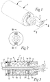
- a machining tool 1 for turning has besides a tool body 2 a member 3 with a cutting insert 4 secured to the tool body. It is pointed out that any other type of such member for chip-removing machining may be secured to an end 5 of the tool body for instead of turning carrying out machining in the form of for example milling, drilling or boring.
- the present invention is directed to the design of the tool body, which is the reason for having said member of the machining tool only shown in fig. 1 .
- the tool body includes a damping apparatus 6 for damping vibrations generated by operation of a machining tool including the tool body.
- This damping apparatus is arranged inside an internal room 7 of the tool body defined by a casing 8.
- the damping apparatus has a damper mass body 9 of a high density material, such as lead.
- This body is provided with an axial through bore 10.
- a central tube 11 for transporting a cooling fluid to cutting edges of a machining tool in operation is rigidly connected to a tool body fixed part 12, 13 at each end thereof and extends through the through bore 10 while leaving a cavity 14 that surrounds the tube between the tube and the through bore such that the central tube and the damper mass body are separated.
- This cavity 14 contains a damping fluid, such as oil.
- a damping fluid may also be present in the space separating the damper mass body 9 and the internal wall of the casing 8.
- an elastic element 15, 16 is located to allow the damper mass body to dampingly interact, for example by shearing, with the respective tool body fixed part 12, 13.
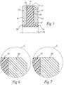
- Rigid disc-like members 17-20 are arranged on each side of each elastic element for clamping the elastic element between two such disc-like members. These members 17-20 connect by an axially directed side 21, 22 (see fig. 5 ) to the damper mass body and by the other to a tool body fixed part.
- one single ring-like piece 30 is formed by two disc-like members 19, 20 having an elastic element 16 arranged therebetween, and such a ring-like piece is formed by applying an adhesive on the sides 23, 24 of the disc-like members directed towards each other and then spraying or pouring an elastomer into the space separating these disc-like members for forming one single piece when the elastomer is cured.
- the elastic element will by such a casting method be provided with two socket-like portions 25, 26 extending axially through a central hole 27 of each disc-like member 19, 20, aligned with a central hole 28 of the elastic element defined by the socket-like portions.
- the socket-like portions 25, 26 project in a rest state of the elastic element shown in fig. 5 axially beyond the respective axially directed side 21, 22 of the respective disc-like member 19, 20.
- the central hole 27 of the disc-like members has a slightly larger diameter than the bore 10 through the damper mass body 9.
- the diameter of the hole 27 can be about two times the wall thickness of the socket-like portions 25, 26.
- the inner diameter of the socket-like portion 25, 26 can be the same as the diameter of the bore 10.
- the socket-like portions 25, 26 cover the walls of the central hole 27 and a passage for the tube 11 with constant diameter is provided through the ring-like piece and the damper mass body.
- the end surface of the socket-like portions 25, 26 that faces the damper mass body 9, abut the damper mass body 9 surrounding the bore 10.
- the tool body fixed parts 12, 13 at each end of the tool body will be moved axially towards the damper mass body 9, such as by turning these tool body fixed parts in threads so as to in an assembled state of the tool body move the opposite sides 21, 22 of each ring-like piece 30 to come to bear against axially directed sides of the damper mass body 9 and a tool body fixed part, respectively, and by that compress said socket-like portions 25, 26 of the elastic elements and cause them to bear under pretention onto the damper mass body and the tool body fixed part, respectively, and by that efficiently seal the cavity 14 surrounding the central tube with respect to the exterior and prevent damping fluid contained therein from leaving the cavity.
- Fig. 6 illustrates an embodiment of the invention in which the outer diameter of the elastic element 16 is the same as the outer diameter of the disc-like members 20, whereas fig. 7 shows an embodiment in which the outer diameter of the elastic element 16' is somewhat larger than the outer diameter of the disc-like member 20' in a rest state of the ring-like piece before assembling of the tool body.
- fig. 7 shows an embodiment in which the outer diameter of the elastic element 16' is somewhat larger than the outer diameter of the disc-like member 20' in a rest state of the ring-like piece before assembling of the tool body.
- the shape of the socket-like portions may be another than the one shown in the figures and will be determined by the mould used when casting the elastic elements between the disc-like members.
Landscapes
- Engineering & Computer Science (AREA)
- Mechanical Engineering (AREA)
- Auxiliary Devices For Machine Tools (AREA)
- Cutting Tools, Boring Holders, And Turrets (AREA)
- Milling Processes (AREA)
Abstract
Description
- The present invention relates to a tool body including a damping apparatus for damping vibrations in a machining tool according to the preamble of
claim 1 as well as a machining tool having such a tool body. - A tool body of the type defined in the introduction is known through
WO 03/093696 - The tool body is provided with such a damping apparatus for damping radial and tangential forces applied on the tool body by the machining action of such a machining tool and by that improving the accuracy of the machining operation and prolonging the lifetime of the cutting edges of the tool. The damping effect of the damping apparatus is a result of an interaction between the damping body, which is of high density material, such as lead, and the elastic element. The elastic element is in this known tool mainly exposed to shear forces.
- The cavity has to be sealed with respect to the exterior by preventing the damping fluid to escape from the cavity along the interface between the respective washer and the damping body and the end piece. An O-ring of rubber is manually fitted to bear between one washer and the damping body, and between one washer and the end piece. Such manual assembly means an inherent risk of a non-tight seal and a not neglectable contribution to production costs in the form of labour costs.
- The object of the present invention is to provide a tool body of the type defined in the introduction being improved in at least some aspect with respect to such tool bodies already known.
- This object is according to the invention obtained by providing such a tool body with the features listed in the characterizing part of appended
claim 1. - Thus, each disc-like member has a central hole aligned with the central hole of the elastic element, and each said elastic element (15, 16) is provided with two socket-like portions extending axially through the central hole (27) of a said disc-like member each, wherein the socket-like portions project in a rest state of the elastic element beyond the respective said axially directed side of the respective disc-like member and which portions are in an assembled state compressed by bearing under pretension onto the damper mass body and the tool body fixed part, respectively, and by that seal the cavity with respect to the exterior.
- These features means that no O-rings are needed and the assembly of the damper apparatus may take place without any manual work, with results in lower production costs and above all a more reliable sealing of said cavity. It has only to be ensured that the damper mass body and the tool body fixed part connecting to each couple of disc-like members on opposite sides thereof have been moved that much towards each other that the projecting socket-like portions of the elastic element are compressed by the damper mass body and the tool body fixed part, respectively.
- Another advantage of such a construction of the elastic elements is that the sealing action may be obtained closer to the cavity than when using O-rings, which need a grove to be applied in and for that sake have to be arranged at a certain distance to the central tube.
- "Socket-like" is to be interpreted to include any shape similar as well as identical to a socket, for example a cylindrical, hollow protrusion.
- "Disc-like" is here to be interpreted to include any shape of such a member similar as well as identical to a disc without any requirement of shape of the large surface thereof, although a circular such surface would mostly be preferred. These disc-like members are stiff and preferably made of metal.
- The invention is not restricted to tool bodies and machining tools for any particular type of machining, and the tool body may for instance have members with cutting edges secured thereto in the form of cutting inserts for chip-removing machining of a work piece by turning, milling, drilling or boring. Thus, both rotating and non-rotating machining tools are comprised.
- According to an embodiment of the invention the socket-like portions of the respective elastic element are the only members sealing the cavities with respect to the exterior. No other sealing means are required due to the reliable sealing action of these socket-like portions when compressed.
- According to an embodiment of the invention the disc-like members of each couple of disc-like members are secured to each other by having the elastic element arranged therebetween secured to both of them while forming one single ring-like piece. This ring-like piece will accordingly have the shape of a thick washer or disc with socket-like portions that cover the walls of the central through-hole of the disc-like members and that project axially from both large sides of that piece. To have the disc-like members of each couple, the elastic element for the damping action and also the socket-like portions for the sealing action as one single piece will facilitate the assembly of the tool body.
- According to an embodiment of the invention each elastic element is secured to the two disc-like members by an adhesive. When constructing said ring-like piece an adhesive may then be applied on the surface of a disc-like member to be directed towards the other disc-like member and the elastic material, such as an elastomer, be sprayed into the space between the disc-like members and cured while reacting with the adhesive for keeping the two disc-like members and the elastic element together as one single piece.
- According to an embodiment of the invention the cavity is filled with a damping fluid in the form of oil.
- According to an embodiment of the invention the central tube is configured to deliver coolant to a said machining tool in operation. In other words, the central tube is a coolant tube.
- According to an embodiment of the invention, the damper mass body has a circular cylindrical shape with a through bore extending according to the central axis of the cylinder so formed. Such a shape of a damper mass body is preferred for a uniform vibration damping action of the damping apparatus.
- According to an embodiment of the invention, the disc-like members have a circular cross-section.
- The invention also relates to a machining tool, a device for sealing a cavity and a use of a tool body according to the appended claims directed to a machining tool, a device for sealing a cavity and a use of a tool body, respectively.
- Other advantageous features as well as advantages of the present invention appear from the description following below.
- With reference to the appended drawings, below follows a specific description of embodiments of the inventions cited as examples.
In the drawings: - Fig. 1
- shows a perspective view of a tool body according to an embodiment of the invention to which a member having a cutting insert for turning is secured,
- Fig. 2
- is a view of the tool body shown in
fig. 1 without said member secured thereto in the direction of the arrow II infig. 1 , - Fig.3
- is a cross section view of the tool body shown in
fig. 1 along the line III-III infig. 2 , - Fig. 4
- is an exploded view of parts of the tool body shown in
fig. 1 , - Fig. 5
- is an enlarged cross section view of a part of a ring-like piece of the tool body shown in
fig. 3 in a rest state thereof before assembling the tool body, and - Fig. 6 and 7
- are enlarged views of the circle C in
fig. 5 for tool bodies according to two different embodiments of the invention. - The construction of a tool body according to the first embodiment of the invention will now be disclosed while making reference simultaneously to
figs. 1-4 . Amachining tool 1 for turning has besides a tool body 2 amember 3 with acutting insert 4 secured to the tool body. It is pointed out that any other type of such member for chip-removing machining may be secured to anend 5 of the tool body for instead of turning carrying out machining in the form of for example milling, drilling or boring. The present invention is directed to the design of the tool body, which is the reason for having said member of the machining tool only shown infig. 1 . - The tool body includes a
damping apparatus 6 for damping vibrations generated by operation of a machining tool including the tool body. This damping apparatus is arranged inside aninternal room 7 of the tool body defined by acasing 8. The damping apparatus has adamper mass body 9 of a high density material, such as lead. This body is provided with an axial throughbore 10. Acentral tube 11 for transporting a cooling fluid to cutting edges of a machining tool in operation is rigidly connected to a tool body fixedpart bore 10 while leaving acavity 14 that surrounds the tube between the tube and the through bore such that the central tube and the damper mass body are separated. Thiscavity 14 contains a damping fluid, such as oil. Such a damping fluid may also be present in the space separating the dampermass body 9 and the internal wall of thecasing 8. - At each axial end of the damper
mass body 9 anelastic element part side 21, 22 (seefig. 5 ) to the damper mass body and by the other to a tool body fixed part. - It is shown in
fig. 4 how one single ring-like piece 30 is formed by two disc-like members elastic element 16 arranged therebetween, and such a ring-like piece is formed by applying an adhesive on thesides like portions central hole 27 of each disc-like member central hole 28 of the elastic element defined by the socket-like portions. The socket-like portions fig. 5 axially beyond the respective axially directedside like member - In the shown embodiment, the
central hole 27 of the disc-like members has a slightly larger diameter than thebore 10 through the dampermass body 9. The diameter of thehole 27 can be about two times the wall thickness of the socket-like portions like portion bore 10. Thus, the socket-like portions central hole 27 and a passage for thetube 11 with constant diameter is provided through the ring-like piece and the damper mass body. The end surface of the socket-like portions mass body 9, abut the dampermass body 9 surrounding thebore 10. - When assembling the tool body, the tool body fixed
parts mass body 9, such as by turning these tool body fixed parts in threads so as to in an assembled state of the tool body move theopposite sides like piece 30 to come to bear against axially directed sides of the dampermass body 9 and a tool body fixed part, respectively, and by that compress said socket-like portions cavity 14 surrounding the central tube with respect to the exterior and prevent damping fluid contained therein from leaving the cavity. -
Fig. 6 illustrates an embodiment of the invention in which the outer diameter of theelastic element 16 is the same as the outer diameter of the disc-like members 20, whereasfig. 7 shows an embodiment in which the outer diameter of the elastic element 16' is somewhat larger than the outer diameter of the disc-like member 20' in a rest state of the ring-like piece before assembling of the tool body. This will then result in also a radial compression of the elastic element upon assembly of the tool body, since the damper mass body and the tool body fixed parts have axial recesses with an inner diameter identical to the outer diameter of the disc-like members for receiving these therein in the assembled state as shown infig. 3 , and the walls defining these recesses will then also reach in over the elastic element and cause a radial compression thereof. - The invention is of course not restricted to the embodiments thereof described above, but many possibilities to modifications thereof would be apparent to a person with skill in the art without departing from the scope of the invention as defined in the appended claims.
- The shape of the socket-like portions may be another than the one shown in the figures and will be determined by the mould used when casting the elastic elements between the disc-like members.
Claims (11)
- A tool body (2) including a damping apparatus for damping vibrations in a machining tool, which machining tool comprises the tool body and a member (3) with at least one cutting edge, wherein the damping apparatus is arranged in an internal room (7) of the tool body and comprises• a damper mass body (9) with an axial through bore (10),• a central tube (11), which is rigidly connected to a tool body fixed part (12, 13) and extends through the through bore (10) while leaving a cavity (14) that surrounds the tube between the tube and the through bore such that the central tube (11) and the damper mass body (9) are separated, wherein the cavity contains a damping fluid,• at each axial end of the damper mass body an elastic element (15, 16) configured to allow the damper mass body (9) to dampingly interact with a tool body fixed part (12, 13) and having a central hole (28) through which the central tube extends, and• a couple of two rigid disc-like members (17-20) for each elastic element (15, 16) for clamping this element therebetween and which members connect, by one axially directed side (21, 22) facing away from the elastic element, to the damper mass body and by the other to a tool body fixed part,
characterized in that• each disc-like member has a central hole (27) aligned with the central hole of the elastic element,• each elastic element (15, 16) is provided with two socket-like portions (25, 26) extending axially through the central hole (27) of a said disc-like member each, wherein• the socket-like portions project in a rest state of the elastic element axially beyond the respective said axially directed side of the respective disc-like member and which portions (25, 26) are in an assembled state compressed by bearing under pretention onto the damper mass body (9) and the tool body fixed part (12, 13), respectively, and by that seal said cavity (14) with respect to the exterior. - A tool body according to claim 1, characterized in that said socket-like portions (25, 26) of the respective elastic element are the only members sealing the cavity (14) with respect to the exterior.
- A tool body according to claim 1 or 2, characterized in that the disc-like members (17-20) of each couple of disc-like members are secured to each other by having the elastic element (15, 16) arranged therebetween secured to both of them while forming one single ring-like piece (30).
- A tool body according to claim 3, characterized in that each said elastic element (15, 16) is secured to the two disc-like members (17-20) by an adhesive.
- A tool body according to any of the preceding claims, characterized in that said cavity (14) is filled with a damping fluid in the form of oil.
- A tool body according to any of the preceding claims, characterized in that the central tube (11) is configured to deliver coolant to a said machining tool in operation.
- A tool body according to any of the preceding claims, characterized in that the damper mass body (9) has a circular cylindrical shape with the through bore (10) extending according to the centre axis of the cylinder so formed.
- A tool body according to any of the preceding claims, characterized in that the disc-like members (17-20) have a circular cross-section.
- A machining tool, characterized in that it has a tool body (2) according to any of the preceding claims.
- A device for sealing a cavity (14) surrounding a tube (11) extending through a through bore (10) of a damper mass body (9) of a damping apparatus for damping vibrations in a machining tool with respect to the exterior, which device comprises two disc-like members (17-20) clamping an elastic element (15, 16) therebetween and having a central hole (27) for allowing the tube to extend therethrough, characterized in that the elastic element (15, 16) is provided with two socket-like portions (25, 26), which portions extend axially through the central hole (27) and project beyond the axially directed side (21, 22) of the respective disc-like member (19) facing away from the other disc-like member (20).
- Use of a tool body according to any of claims 1-8 to damp vibrations in a machining tool in operation.
Priority Applications (7)
| Application Number | Priority Date | Filing Date | Title |
|---|---|---|---|
| EP16191181.3A EP3300820B1 (en) | 2016-09-28 | 2016-09-28 | A tool body including a damping apparatus and a machining tool having such a tool body |
| CN201780059192.5A CN109789491B (en) | 2016-09-28 | 2017-08-29 | Tool body comprising a damping device and machining tool having such a tool body |
| JP2019516212A JP7050766B2 (en) | 2016-09-28 | 2017-08-29 | Tool bodies with damping devices and machining tools with such tool bodies |
| US16/337,384 US11583937B2 (en) | 2016-09-28 | 2017-08-29 | Tool body including a damping apparatus and a machining tool having such a tool body |
| CA3035304A CA3035304C (en) | 2016-09-28 | 2017-08-29 | A tool body including a damping apparatus and a machining tool having such a tool body |
| RU2019112669A RU2019112669A (en) | 2016-09-28 | 2017-08-29 | TOOL BODY INCLUDING DAMPER AND CUTTING TOOL HAVING SUCH TOOL BODY |
| PCT/EP2017/071656 WO2018059861A1 (en) | 2016-09-28 | 2017-08-29 | A tool body including a damping apparatus and a machining tool having such a tool body |
Applications Claiming Priority (1)
| Application Number | Priority Date | Filing Date | Title |
|---|---|---|---|
| EP16191181.3A EP3300820B1 (en) | 2016-09-28 | 2016-09-28 | A tool body including a damping apparatus and a machining tool having such a tool body |
Publications (2)
| Publication Number | Publication Date |
|---|---|
| EP3300820A1 true EP3300820A1 (en) | 2018-04-04 |
| EP3300820B1 EP3300820B1 (en) | 2020-11-18 |
Family
ID=57103830
Family Applications (1)
| Application Number | Title | Priority Date | Filing Date |
|---|---|---|---|
| EP16191181.3A Active EP3300820B1 (en) | 2016-09-28 | 2016-09-28 | A tool body including a damping apparatus and a machining tool having such a tool body |
Country Status (6)
| Country | Link |
|---|---|
| US (1) | US11583937B2 (en) |
| EP (1) | EP3300820B1 (en) |
| JP (1) | JP7050766B2 (en) |
| CN (1) | CN109789491B (en) |
| RU (1) | RU2019112669A (en) |
| WO (1) | WO2018059861A1 (en) |
Cited By (3)
| Publication number | Priority date | Publication date | Assignee | Title |
|---|---|---|---|---|
| WO2020050756A1 (en) * | 2018-09-07 | 2020-03-12 | Maq Ab | Mass damper device and working tool |
| WO2021197577A1 (en) * | 2020-03-31 | 2021-10-07 | Maq Ab | Tool holder for tool assembly and tool assembly comprising tool holder |
| EP4029636A1 (en) | 2021-01-19 | 2022-07-20 | KOMET Deutschland GmbH | Tool base and chip removing tool |
Families Citing this family (2)
| Publication number | Priority date | Publication date | Assignee | Title |
|---|---|---|---|---|
| DE102020134531A1 (en) * | 2020-12-22 | 2022-06-23 | Hubert Kimmich | boring bar assembly |
| JP7583922B2 (en) * | 2021-05-07 | 2024-11-14 | 京セラ株式会社 | Holder, cutting tool, and method for manufacturing machined product |
Citations (3)
| Publication number | Priority date | Publication date | Assignee | Title |
|---|---|---|---|---|
| GB1199661A (en) * | 1967-08-21 | 1970-07-22 | Greene Tweed & Co Inc | Improvements in or relating to Sealing Assemblies |
| WO2003093696A2 (en) | 2002-04-30 | 2003-11-13 | Teeness As | Damping apparatus for the damping of vibrations |
| US20160067787A1 (en) * | 2014-09-09 | 2016-03-10 | Enrico R. Giannetti | Machine tool having anti-vibration tuning mechanism for chatter minimized machining |
Family Cites Families (6)
| Publication number | Priority date | Publication date | Assignee | Title |
|---|---|---|---|---|
| GB199661A (en) | 1922-07-06 | 1923-06-28 | Fraisse Freres | Process for automatic and rapid manufacture of crystallised or preserved fruit |
| US4553884A (en) * | 1982-05-10 | 1985-11-19 | Kennametal Inc. | Boring tool and method of reducing vibrations therein |
| JP4648072B2 (en) * | 2005-04-28 | 2011-03-09 | 株式会社日立プラントテクノロジー | Tool with damper and method of manufacturing impeller or guide vane of fluid machine using the same |
| US9669471B2 (en) * | 2010-03-11 | 2017-06-06 | Cumberland & Western Resources, Llc | Devices for isolating acoustic vibrations in metalworking systems |
| US9061355B2 (en) * | 2012-06-29 | 2015-06-23 | Kennametal Inc. | Tool adaptor having an integrated damping device |
| FR3007305B1 (en) * | 2013-06-20 | 2015-07-17 | Seco E P B | AXIAL MOBILE ELEMENT FOR ROTARY TOOL DAMPING SYSTEM |
-
2016
- 2016-09-28 EP EP16191181.3A patent/EP3300820B1/en active Active
-
2017
- 2017-08-29 RU RU2019112669A patent/RU2019112669A/en not_active Application Discontinuation
- 2017-08-29 JP JP2019516212A patent/JP7050766B2/en active Active
- 2017-08-29 CN CN201780059192.5A patent/CN109789491B/en active Active
- 2017-08-29 US US16/337,384 patent/US11583937B2/en active Active
- 2017-08-29 WO PCT/EP2017/071656 patent/WO2018059861A1/en not_active Ceased
Patent Citations (3)
| Publication number | Priority date | Publication date | Assignee | Title |
|---|---|---|---|---|
| GB1199661A (en) * | 1967-08-21 | 1970-07-22 | Greene Tweed & Co Inc | Improvements in or relating to Sealing Assemblies |
| WO2003093696A2 (en) | 2002-04-30 | 2003-11-13 | Teeness As | Damping apparatus for the damping of vibrations |
| US20160067787A1 (en) * | 2014-09-09 | 2016-03-10 | Enrico R. Giannetti | Machine tool having anti-vibration tuning mechanism for chatter minimized machining |
Cited By (8)
| Publication number | Priority date | Publication date | Assignee | Title |
|---|---|---|---|---|
| WO2020050756A1 (en) * | 2018-09-07 | 2020-03-12 | Maq Ab | Mass damper device and working tool |
| WO2020049167A1 (en) | 2018-09-07 | 2020-03-12 | Maq Ab | Mass damper device, working tool and working tool holder comprising a mass damper device |
| JP2021536557A (en) * | 2018-09-07 | 2021-12-27 | エムエーキュー アーベー | Mass damper device, machining tool with mass damper device, and machining tool holder with mass damper device |
| US12442428B2 (en) | 2018-09-07 | 2025-10-14 | Maq Ab | Mass damper device, working tool and working tool holder comprising a mass damper device |
| WO2021197577A1 (en) * | 2020-03-31 | 2021-10-07 | Maq Ab | Tool holder for tool assembly and tool assembly comprising tool holder |
| US12583040B2 (en) | 2020-03-31 | 2026-03-24 | Maq Ab | Tool holder for tool assembly and tool assembly comprising tool holder |
| EP4029636A1 (en) | 2021-01-19 | 2022-07-20 | KOMET Deutschland GmbH | Tool base and chip removing tool |
| WO2022156954A1 (en) | 2021-01-19 | 2022-07-28 | Komet Deutschland Gmbh | Tool main part and cutting tool |
Also Published As
| Publication number | Publication date |
|---|---|
| RU2019112669A (en) | 2020-10-29 |
| CN109789491A (en) | 2019-05-21 |
| US20210354205A1 (en) | 2021-11-18 |
| US11583937B2 (en) | 2023-02-21 |
| JP7050766B2 (en) | 2022-04-08 |
| CA3035304A1 (en) | 2018-04-05 |
| EP3300820B1 (en) | 2020-11-18 |
| CN109789491B (en) | 2020-11-10 |
| JP2019529141A (en) | 2019-10-17 |
| WO2018059861A1 (en) | 2018-04-05 |
Similar Documents
| Publication | Publication Date | Title |
|---|---|---|
| US11583937B2 (en) | Tool body including a damping apparatus and a machining tool having such a tool body | |
| TWI810278B (en) | Tool holder having integrally formed anti-vibration component and cutting tool provided with tool holder | |
| EP2953750B1 (en) | Tool chuck with vibration reduction | |
| US11713625B2 (en) | Bulkhead | |
| US9630258B2 (en) | Tool holder assembly with dampening elements | |
| KR20120134002A (en) | Burr remove apparatus | |
| RU2004131850A (en) | DAMPING DEVICE FOR RELAXING OSCILLATIONS | |
| CN103154563A (en) | Vibration damping mechanism | |
| CN1942275B (en) | Expansion clamping device | |
| KR20200020845A (en) | Damping device and tool-holding device with such damping device | |
| KR20180096569A (en) | Tool holder | |
| CA3035304C (en) | A tool body including a damping apparatus and a machining tool having such a tool body | |
| KR20070002087A (en) | Radial Vibration Motors and Manufacturing Methods thereof | |
| US6098441A (en) | Method for forming a through-hole through the circumferential wall of a metal pipe and a metal pipe worked by the said method | |
| US20200056651A1 (en) | Sealing Bellows For A Ball And Socket Joint Comprising Such A Sealing Bellows | |
| JPWO2019187220A1 (en) | Manufacturing method of cylinder device and rod | |
| JP6716474B2 (en) | Vibrating element with separated components | |
| US7228785B2 (en) | Piston rod for a vibration damper with amplitude-dependent damping force | |
| KR101825640B1 (en) | The collet fixture for preventing the ingress of foreign matter | |
| US10913320B2 (en) | Suspension bearing lubricating system | |
| RU2020134567A (en) | TOOL HOLDER HAVING ONE ONE ANTI-VIBRATION COMPONENT AND CUTTING TOOL PROVIDED WITH TOOL HOLDER | |
| US10213840B2 (en) | Blade fastening device having a waterproof arrangement | |
| DE102009002973A1 (en) | Hand-held machine tool i.e. electric hand-held machine tool, has vibration reduction element coordinating with grip part and comprising vibration reduction fluid in damper area that experiences state change | |
| US20130092278A1 (en) | Apparatus for improving flow between intersecting passageways | |
| BG2532U1 (en) | A device for dapmening vibrations |
Legal Events
| Date | Code | Title | Description |
|---|---|---|---|
| PUAI | Public reference made under article 153(3) epc to a published international application that has entered the european phase |
Free format text: ORIGINAL CODE: 0009012 |
|
| STAA | Information on the status of an ep patent application or granted ep patent |
Free format text: STATUS: THE APPLICATION HAS BEEN PUBLISHED |
|
| AK | Designated contracting states |
Kind code of ref document: A1 Designated state(s): AL AT BE BG CH CY CZ DE DK EE ES FI FR GB GR HR HU IE IS IT LI LT LU LV MC MK MT NL NO PL PT RO RS SE SI SK SM TR |
|
| AX | Request for extension of the european patent |
Extension state: BA ME |
|
| STAA | Information on the status of an ep patent application or granted ep patent |
Free format text: STATUS: REQUEST FOR EXAMINATION WAS MADE |
|
| 17P | Request for examination filed |
Effective date: 20181004 |
|
| RBV | Designated contracting states (corrected) |
Designated state(s): AL AT BE BG CH CY CZ DE DK EE ES FI FR GB GR HR HU IE IS IT LI LT LU LV MC MK MT NL NO PL PT RO RS SE SI SK SM TR |
|
| GRAP | Despatch of communication of intention to grant a patent |
Free format text: ORIGINAL CODE: EPIDOSNIGR1 |
|
| STAA | Information on the status of an ep patent application or granted ep patent |
Free format text: STATUS: GRANT OF PATENT IS INTENDED |
|
| INTG | Intention to grant announced |
Effective date: 20200622 |
|
| GRAS | Grant fee paid |
Free format text: ORIGINAL CODE: EPIDOSNIGR3 |
|
| GRAA | (expected) grant |
Free format text: ORIGINAL CODE: 0009210 |
|
| STAA | Information on the status of an ep patent application or granted ep patent |
Free format text: STATUS: THE PATENT HAS BEEN GRANTED |
|
| AK | Designated contracting states |
Kind code of ref document: B1 Designated state(s): AL AT BE BG CH CY CZ DE DK EE ES FI FR GB GR HR HU IE IS IT LI LT LU LV MC MK MT NL NO PL PT RO RS SE SI SK SM TR |
|
| REG | Reference to a national code |
Ref country code: GB Ref legal event code: FG4D |
|
| REG | Reference to a national code |
Ref country code: CH Ref legal event code: EP |
|
| REG | Reference to a national code |
Ref country code: IE Ref legal event code: FG4D |
|
| REG | Reference to a national code |
Ref country code: DE Ref legal event code: R096 Ref document number: 602016047986 Country of ref document: DE |
|
| REG | Reference to a national code |
Ref country code: AT Ref legal event code: REF Ref document number: 1335197 Country of ref document: AT Kind code of ref document: T Effective date: 20201215 |
|
| REG | Reference to a national code |
Ref country code: AT Ref legal event code: MK05 Ref document number: 1335197 Country of ref document: AT Kind code of ref document: T Effective date: 20201118 |
|
| REG | Reference to a national code |
Ref country code: NL Ref legal event code: MP Effective date: 20201118 |
|
| PG25 | Lapsed in a contracting state [announced via postgrant information from national office to epo] |
Ref country code: PT Free format text: LAPSE BECAUSE OF FAILURE TO SUBMIT A TRANSLATION OF THE DESCRIPTION OR TO PAY THE FEE WITHIN THE PRESCRIBED TIME-LIMIT Effective date: 20210318 Ref country code: RS Free format text: LAPSE BECAUSE OF FAILURE TO SUBMIT A TRANSLATION OF THE DESCRIPTION OR TO PAY THE FEE WITHIN THE PRESCRIBED TIME-LIMIT Effective date: 20201118 Ref country code: NO Free format text: LAPSE BECAUSE OF FAILURE TO SUBMIT A TRANSLATION OF THE DESCRIPTION OR TO PAY THE FEE WITHIN THE PRESCRIBED TIME-LIMIT Effective date: 20210218 Ref country code: FI Free format text: LAPSE BECAUSE OF FAILURE TO SUBMIT A TRANSLATION OF THE DESCRIPTION OR TO PAY THE FEE WITHIN THE PRESCRIBED TIME-LIMIT Effective date: 20201118 Ref country code: GR Free format text: LAPSE BECAUSE OF FAILURE TO SUBMIT A TRANSLATION OF THE DESCRIPTION OR TO PAY THE FEE WITHIN THE PRESCRIBED TIME-LIMIT Effective date: 20210219 |
|
| PG25 | Lapsed in a contracting state [announced via postgrant information from national office to epo] |
Ref country code: SE Free format text: LAPSE BECAUSE OF FAILURE TO SUBMIT A TRANSLATION OF THE DESCRIPTION OR TO PAY THE FEE WITHIN THE PRESCRIBED TIME-LIMIT Effective date: 20201118 Ref country code: BG Free format text: LAPSE BECAUSE OF FAILURE TO SUBMIT A TRANSLATION OF THE DESCRIPTION OR TO PAY THE FEE WITHIN THE PRESCRIBED TIME-LIMIT Effective date: 20210218 Ref country code: IS Free format text: LAPSE BECAUSE OF FAILURE TO SUBMIT A TRANSLATION OF THE DESCRIPTION OR TO PAY THE FEE WITHIN THE PRESCRIBED TIME-LIMIT Effective date: 20210318 Ref country code: LV Free format text: LAPSE BECAUSE OF FAILURE TO SUBMIT A TRANSLATION OF THE DESCRIPTION OR TO PAY THE FEE WITHIN THE PRESCRIBED TIME-LIMIT Effective date: 20201118 Ref country code: PL Free format text: LAPSE BECAUSE OF FAILURE TO SUBMIT A TRANSLATION OF THE DESCRIPTION OR TO PAY THE FEE WITHIN THE PRESCRIBED TIME-LIMIT Effective date: 20201118 Ref country code: AT Free format text: LAPSE BECAUSE OF FAILURE TO SUBMIT A TRANSLATION OF THE DESCRIPTION OR TO PAY THE FEE WITHIN THE PRESCRIBED TIME-LIMIT Effective date: 20201118 |
|
| REG | Reference to a national code |
Ref country code: LT Ref legal event code: MG9D |
|
| PG25 | Lapsed in a contracting state [announced via postgrant information from national office to epo] |
Ref country code: HR Free format text: LAPSE BECAUSE OF FAILURE TO SUBMIT A TRANSLATION OF THE DESCRIPTION OR TO PAY THE FEE WITHIN THE PRESCRIBED TIME-LIMIT Effective date: 20201118 |
|
| PG25 | Lapsed in a contracting state [announced via postgrant information from national office to epo] |
Ref country code: RO Free format text: LAPSE BECAUSE OF FAILURE TO SUBMIT A TRANSLATION OF THE DESCRIPTION OR TO PAY THE FEE WITHIN THE PRESCRIBED TIME-LIMIT Effective date: 20201118 Ref country code: SK Free format text: LAPSE BECAUSE OF FAILURE TO SUBMIT A TRANSLATION OF THE DESCRIPTION OR TO PAY THE FEE WITHIN THE PRESCRIBED TIME-LIMIT Effective date: 20201118 Ref country code: SM Free format text: LAPSE BECAUSE OF FAILURE TO SUBMIT A TRANSLATION OF THE DESCRIPTION OR TO PAY THE FEE WITHIN THE PRESCRIBED TIME-LIMIT Effective date: 20201118 Ref country code: LT Free format text: LAPSE BECAUSE OF FAILURE TO SUBMIT A TRANSLATION OF THE DESCRIPTION OR TO PAY THE FEE WITHIN THE PRESCRIBED TIME-LIMIT Effective date: 20201118 Ref country code: EE Free format text: LAPSE BECAUSE OF FAILURE TO SUBMIT A TRANSLATION OF THE DESCRIPTION OR TO PAY THE FEE WITHIN THE PRESCRIBED TIME-LIMIT Effective date: 20201118 Ref country code: CZ Free format text: LAPSE BECAUSE OF FAILURE TO SUBMIT A TRANSLATION OF THE DESCRIPTION OR TO PAY THE FEE WITHIN THE PRESCRIBED TIME-LIMIT Effective date: 20201118 |
|
| REG | Reference to a national code |
Ref country code: DE Ref legal event code: R097 Ref document number: 602016047986 Country of ref document: DE |
|
| PG25 | Lapsed in a contracting state [announced via postgrant information from national office to epo] |
Ref country code: DK Free format text: LAPSE BECAUSE OF FAILURE TO SUBMIT A TRANSLATION OF THE DESCRIPTION OR TO PAY THE FEE WITHIN THE PRESCRIBED TIME-LIMIT Effective date: 20201118 |
|
| PLBE | No opposition filed within time limit |
Free format text: ORIGINAL CODE: 0009261 |
|
| STAA | Information on the status of an ep patent application or granted ep patent |
Free format text: STATUS: NO OPPOSITION FILED WITHIN TIME LIMIT |
|
| 26N | No opposition filed |
Effective date: 20210819 |
|
| PG25 | Lapsed in a contracting state [announced via postgrant information from national office to epo] |
Ref country code: NL Free format text: LAPSE BECAUSE OF FAILURE TO SUBMIT A TRANSLATION OF THE DESCRIPTION OR TO PAY THE FEE WITHIN THE PRESCRIBED TIME-LIMIT Effective date: 20201118 Ref country code: AL Free format text: LAPSE BECAUSE OF FAILURE TO SUBMIT A TRANSLATION OF THE DESCRIPTION OR TO PAY THE FEE WITHIN THE PRESCRIBED TIME-LIMIT Effective date: 20201118 |
|
| PG25 | Lapsed in a contracting state [announced via postgrant information from national office to epo] |
Ref country code: SI Free format text: LAPSE BECAUSE OF FAILURE TO SUBMIT A TRANSLATION OF THE DESCRIPTION OR TO PAY THE FEE WITHIN THE PRESCRIBED TIME-LIMIT Effective date: 20201118 |
|
| PG25 | Lapsed in a contracting state [announced via postgrant information from national office to epo] |
Ref country code: ES Free format text: LAPSE BECAUSE OF FAILURE TO SUBMIT A TRANSLATION OF THE DESCRIPTION OR TO PAY THE FEE WITHIN THE PRESCRIBED TIME-LIMIT Effective date: 20201118 |
|
| REG | Reference to a national code |
Ref country code: CH Ref legal event code: PL |
|
| REG | Reference to a national code |
Ref country code: BE Ref legal event code: MM Effective date: 20210930 |
|
| PG25 | Lapsed in a contracting state [announced via postgrant information from national office to epo] |
Ref country code: IS Free format text: LAPSE BECAUSE OF FAILURE TO SUBMIT A TRANSLATION OF THE DESCRIPTION OR TO PAY THE FEE WITHIN THE PRESCRIBED TIME-LIMIT Effective date: 20210318 Ref country code: MC Free format text: LAPSE BECAUSE OF FAILURE TO SUBMIT A TRANSLATION OF THE DESCRIPTION OR TO PAY THE FEE WITHIN THE PRESCRIBED TIME-LIMIT Effective date: 20201118 |
|
| PG25 | Lapsed in a contracting state [announced via postgrant information from national office to epo] |
Ref country code: LU Free format text: LAPSE BECAUSE OF NON-PAYMENT OF DUE FEES Effective date: 20210928 Ref country code: IE Free format text: LAPSE BECAUSE OF NON-PAYMENT OF DUE FEES Effective date: 20210928 Ref country code: BE Free format text: LAPSE BECAUSE OF NON-PAYMENT OF DUE FEES Effective date: 20210930 |
|
| PG25 | Lapsed in a contracting state [announced via postgrant information from national office to epo] |
Ref country code: LI Free format text: LAPSE BECAUSE OF NON-PAYMENT OF DUE FEES Effective date: 20210930 Ref country code: CH Free format text: LAPSE BECAUSE OF NON-PAYMENT OF DUE FEES Effective date: 20210930 |
|
| PG25 | Lapsed in a contracting state [announced via postgrant information from national office to epo] |
Ref country code: HU Free format text: LAPSE BECAUSE OF FAILURE TO SUBMIT A TRANSLATION OF THE DESCRIPTION OR TO PAY THE FEE WITHIN THE PRESCRIBED TIME-LIMIT; INVALID AB INITIO Effective date: 20160928 |
|
| PG25 | Lapsed in a contracting state [announced via postgrant information from national office to epo] |
Ref country code: CY Free format text: LAPSE BECAUSE OF FAILURE TO SUBMIT A TRANSLATION OF THE DESCRIPTION OR TO PAY THE FEE WITHIN THE PRESCRIBED TIME-LIMIT Effective date: 20201118 |
|
| PG25 | Lapsed in a contracting state [announced via postgrant information from national office to epo] |
Ref country code: MK Free format text: LAPSE BECAUSE OF FAILURE TO SUBMIT A TRANSLATION OF THE DESCRIPTION OR TO PAY THE FEE WITHIN THE PRESCRIBED TIME-LIMIT Effective date: 20201118 |
|
| PG25 | Lapsed in a contracting state [announced via postgrant information from national office to epo] |
Ref country code: MT Free format text: LAPSE BECAUSE OF FAILURE TO SUBMIT A TRANSLATION OF THE DESCRIPTION OR TO PAY THE FEE WITHIN THE PRESCRIBED TIME-LIMIT Effective date: 20201118 |
|
| PGFP | Annual fee paid to national office [announced via postgrant information from national office to epo] |
Ref country code: DE Payment date: 20250805 Year of fee payment: 10 |
|
| PGFP | Annual fee paid to national office [announced via postgrant information from national office to epo] |
Ref country code: IT Payment date: 20250825 Year of fee payment: 10 |
|
| PGFP | Annual fee paid to national office [announced via postgrant information from national office to epo] |
Ref country code: GB Payment date: 20250807 Year of fee payment: 10 |
|
| PGFP | Annual fee paid to national office [announced via postgrant information from national office to epo] |
Ref country code: FR Payment date: 20250821 Year of fee payment: 10 |
|
| PG25 | Lapsed in a contracting state [announced via postgrant information from national office to epo] |
Ref country code: TR Free format text: LAPSE BECAUSE OF FAILURE TO SUBMIT A TRANSLATION OF THE DESCRIPTION OR TO PAY THE FEE WITHIN THE PRESCRIBED TIME-LIMIT Effective date: 20201118 |