EP3300710A1 - Walking training apparatus and its control method - Google Patents
Walking training apparatus and its control method Download PDFInfo
- Publication number
- EP3300710A1 EP3300710A1 EP17187885.3A EP17187885A EP3300710A1 EP 3300710 A1 EP3300710 A1 EP 3300710A1 EP 17187885 A EP17187885 A EP 17187885A EP 3300710 A1 EP3300710 A1 EP 3300710A1
- Authority
- EP
- European Patent Office
- Prior art keywords
- leg
- driving force
- winding mechanism
- wire winding
- period
- Prior art date
- Legal status (The legal status is an assumption and is not a legal conclusion. Google has not performed a legal analysis and makes no representation as to the accuracy of the status listed.)
- Granted
Links
Images




Classifications
-
- A—HUMAN NECESSITIES
- A61—MEDICAL OR VETERINARY SCIENCE; HYGIENE
- A61H—PHYSICAL THERAPY APPARATUS, e.g. DEVICES FOR LOCATING OR STIMULATING REFLEX POINTS IN THE BODY; ARTIFICIAL RESPIRATION; MASSAGE; BATHING DEVICES FOR SPECIAL THERAPEUTIC OR HYGIENIC PURPOSES OR SPECIFIC PARTS OF THE BODY
- A61H1/00—Apparatus for passive exercising; Vibrating apparatus; Chiropractic devices, e.g. body impacting devices, external devices for briefly extending or aligning unbroken bones
- A61H1/02—Stretching or bending or torsioning apparatus for exercising
- A61H1/0237—Stretching or bending or torsioning apparatus for exercising for the lower limbs
- A61H1/0255—Both knee and hip of a patient, e.g. in supine or sitting position, the feet being moved together in a plane substantially parallel to the body-symmetrical plane
- A61H1/0262—Walking movement; Appliances for aiding disabled persons to walk
-
- A—HUMAN NECESSITIES
- A61—MEDICAL OR VETERINARY SCIENCE; HYGIENE
- A61H—PHYSICAL THERAPY APPARATUS, e.g. DEVICES FOR LOCATING OR STIMULATING REFLEX POINTS IN THE BODY; ARTIFICIAL RESPIRATION; MASSAGE; BATHING DEVICES FOR SPECIAL THERAPEUTIC OR HYGIENIC PURPOSES OR SPECIFIC PARTS OF THE BODY
- A61H1/00—Apparatus for passive exercising; Vibrating apparatus; Chiropractic devices, e.g. body impacting devices, external devices for briefly extending or aligning unbroken bones
- A61H1/02—Stretching or bending or torsioning apparatus for exercising
- A61H1/0218—Drawing-out devices
- A61H1/0229—Drawing-out devices by reducing gravity forces normally applied to the body, e.g. by lifting or hanging the body or part of it
-
- A—HUMAN NECESSITIES
- A61—MEDICAL OR VETERINARY SCIENCE; HYGIENE
- A61H—PHYSICAL THERAPY APPARATUS, e.g. DEVICES FOR LOCATING OR STIMULATING REFLEX POINTS IN THE BODY; ARTIFICIAL RESPIRATION; MASSAGE; BATHING DEVICES FOR SPECIAL THERAPEUTIC OR HYGIENIC PURPOSES OR SPECIFIC PARTS OF THE BODY
- A61H1/00—Apparatus for passive exercising; Vibrating apparatus; Chiropractic devices, e.g. body impacting devices, external devices for briefly extending or aligning unbroken bones
- A61H1/02—Stretching or bending or torsioning apparatus for exercising
- A61H1/0237—Stretching or bending or torsioning apparatus for exercising for the lower limbs
- A61H1/024—Knee
-
- A—HUMAN NECESSITIES
- A61—MEDICAL OR VETERINARY SCIENCE; HYGIENE
- A61H—PHYSICAL THERAPY APPARATUS, e.g. DEVICES FOR LOCATING OR STIMULATING REFLEX POINTS IN THE BODY; ARTIFICIAL RESPIRATION; MASSAGE; BATHING DEVICES FOR SPECIAL THERAPEUTIC OR HYGIENIC PURPOSES OR SPECIFIC PARTS OF THE BODY
- A61H1/00—Apparatus for passive exercising; Vibrating apparatus; Chiropractic devices, e.g. body impacting devices, external devices for briefly extending or aligning unbroken bones
- A61H1/02—Stretching or bending or torsioning apparatus for exercising
- A61H1/0237—Stretching or bending or torsioning apparatus for exercising for the lower limbs
- A61H1/0244—Hip
-
- A—HUMAN NECESSITIES
- A61—MEDICAL OR VETERINARY SCIENCE; HYGIENE
- A61H—PHYSICAL THERAPY APPARATUS, e.g. DEVICES FOR LOCATING OR STIMULATING REFLEX POINTS IN THE BODY; ARTIFICIAL RESPIRATION; MASSAGE; BATHING DEVICES FOR SPECIAL THERAPEUTIC OR HYGIENIC PURPOSES OR SPECIFIC PARTS OF THE BODY
- A61H1/00—Apparatus for passive exercising; Vibrating apparatus; Chiropractic devices, e.g. body impacting devices, external devices for briefly extending or aligning unbroken bones
- A61H1/02—Stretching or bending or torsioning apparatus for exercising
- A61H1/0237—Stretching or bending or torsioning apparatus for exercising for the lower limbs
- A61H1/0266—Foot
-
- A—HUMAN NECESSITIES
- A61—MEDICAL OR VETERINARY SCIENCE; HYGIENE
- A61H—PHYSICAL THERAPY APPARATUS, e.g. DEVICES FOR LOCATING OR STIMULATING REFLEX POINTS IN THE BODY; ARTIFICIAL RESPIRATION; MASSAGE; BATHING DEVICES FOR SPECIAL THERAPEUTIC OR HYGIENIC PURPOSES OR SPECIFIC PARTS OF THE BODY
- A61H3/00—Appliances for aiding patients or disabled persons to walk about
-
- A—HUMAN NECESSITIES
- A61—MEDICAL OR VETERINARY SCIENCE; HYGIENE
- A61H—PHYSICAL THERAPY APPARATUS, e.g. DEVICES FOR LOCATING OR STIMULATING REFLEX POINTS IN THE BODY; ARTIFICIAL RESPIRATION; MASSAGE; BATHING DEVICES FOR SPECIAL THERAPEUTIC OR HYGIENIC PURPOSES OR SPECIFIC PARTS OF THE BODY
- A61H3/00—Appliances for aiding patients or disabled persons to walk about
- A61H3/008—Appliances for aiding patients or disabled persons to walk about using suspension devices for supporting the body in an upright walking or standing position, e.g. harnesses
-
- A—HUMAN NECESSITIES
- A63—SPORTS; GAMES; AMUSEMENTS
- A63B—APPARATUS FOR PHYSICAL TRAINING, GYMNASTICS, SWIMMING, CLIMBING, OR FENCING; BALL GAMES; TRAINING EQUIPMENT
- A63B21/00—Exercising apparatus for developing or strengthening the muscles or joints of the body by working against a counterforce, with or without measuring devices
- A63B21/00181—Exercising apparatus for developing or strengthening the muscles or joints of the body by working against a counterforce, with or without measuring devices comprising additional means assisting the user to overcome part of the resisting force, i.e. assisted-active exercising
-
- A—HUMAN NECESSITIES
- A63—SPORTS; GAMES; AMUSEMENTS
- A63B—APPARATUS FOR PHYSICAL TRAINING, GYMNASTICS, SWIMMING, CLIMBING, OR FENCING; BALL GAMES; TRAINING EQUIPMENT
- A63B22/00—Exercising apparatus specially adapted for conditioning the cardio-vascular system, for training agility or co-ordination of movements
- A63B22/02—Exercising apparatus specially adapted for conditioning the cardio-vascular system, for training agility or co-ordination of movements with movable endless bands, e.g. treadmills
-
- A—HUMAN NECESSITIES
- A63—SPORTS; GAMES; AMUSEMENTS
- A63B—APPARATUS FOR PHYSICAL TRAINING, GYMNASTICS, SWIMMING, CLIMBING, OR FENCING; BALL GAMES; TRAINING EQUIPMENT
- A63B22/00—Exercising apparatus specially adapted for conditioning the cardio-vascular system, for training agility or co-ordination of movements
- A63B22/02—Exercising apparatus specially adapted for conditioning the cardio-vascular system, for training agility or co-ordination of movements with movable endless bands, e.g. treadmills
- A63B22/0235—Exercising apparatus specially adapted for conditioning the cardio-vascular system, for training agility or co-ordination of movements with movable endless bands, e.g. treadmills driven by a motor
-
- A—HUMAN NECESSITIES
- A61—MEDICAL OR VETERINARY SCIENCE; HYGIENE
- A61H—PHYSICAL THERAPY APPARATUS, e.g. DEVICES FOR LOCATING OR STIMULATING REFLEX POINTS IN THE BODY; ARTIFICIAL RESPIRATION; MASSAGE; BATHING DEVICES FOR SPECIAL THERAPEUTIC OR HYGIENIC PURPOSES OR SPECIFIC PARTS OF THE BODY
- A61H1/00—Apparatus for passive exercising; Vibrating apparatus; Chiropractic devices, e.g. body impacting devices, external devices for briefly extending or aligning unbroken bones
- A61H1/02—Stretching or bending or torsioning apparatus for exercising
- A61H2001/0207—Nutating movement of a body part around its articulation
-
- A—HUMAN NECESSITIES
- A61—MEDICAL OR VETERINARY SCIENCE; HYGIENE
- A61H—PHYSICAL THERAPY APPARATUS, e.g. DEVICES FOR LOCATING OR STIMULATING REFLEX POINTS IN THE BODY; ARTIFICIAL RESPIRATION; MASSAGE; BATHING DEVICES FOR SPECIAL THERAPEUTIC OR HYGIENIC PURPOSES OR SPECIFIC PARTS OF THE BODY
- A61H1/00—Apparatus for passive exercising; Vibrating apparatus; Chiropractic devices, e.g. body impacting devices, external devices for briefly extending or aligning unbroken bones
- A61H1/02—Stretching or bending or torsioning apparatus for exercising
- A61H2001/0211—Walking coordination of arms and legs
-
- A—HUMAN NECESSITIES
- A61—MEDICAL OR VETERINARY SCIENCE; HYGIENE
- A61H—PHYSICAL THERAPY APPARATUS, e.g. DEVICES FOR LOCATING OR STIMULATING REFLEX POINTS IN THE BODY; ARTIFICIAL RESPIRATION; MASSAGE; BATHING DEVICES FOR SPECIAL THERAPEUTIC OR HYGIENIC PURPOSES OR SPECIFIC PARTS OF THE BODY
- A61H2201/00—Characteristics of apparatus not provided for in the preceding codes
- A61H2201/01—Constructive details
- A61H2201/0173—Means for preventing injuries
-
- A—HUMAN NECESSITIES
- A61—MEDICAL OR VETERINARY SCIENCE; HYGIENE
- A61H—PHYSICAL THERAPY APPARATUS, e.g. DEVICES FOR LOCATING OR STIMULATING REFLEX POINTS IN THE BODY; ARTIFICIAL RESPIRATION; MASSAGE; BATHING DEVICES FOR SPECIAL THERAPEUTIC OR HYGIENIC PURPOSES OR SPECIFIC PARTS OF THE BODY
- A61H2201/00—Characteristics of apparatus not provided for in the preceding codes
- A61H2201/12—Driving means
- A61H2201/1207—Driving means with electric or magnetic drive
-
- A—HUMAN NECESSITIES
- A61—MEDICAL OR VETERINARY SCIENCE; HYGIENE
- A61H—PHYSICAL THERAPY APPARATUS, e.g. DEVICES FOR LOCATING OR STIMULATING REFLEX POINTS IN THE BODY; ARTIFICIAL RESPIRATION; MASSAGE; BATHING DEVICES FOR SPECIAL THERAPEUTIC OR HYGIENIC PURPOSES OR SPECIFIC PARTS OF THE BODY
- A61H2201/00—Characteristics of apparatus not provided for in the preceding codes
- A61H2201/12—Driving means
- A61H2201/1207—Driving means with electric or magnetic drive
- A61H2201/1215—Rotary drive
-
- A—HUMAN NECESSITIES
- A61—MEDICAL OR VETERINARY SCIENCE; HYGIENE
- A61H—PHYSICAL THERAPY APPARATUS, e.g. DEVICES FOR LOCATING OR STIMULATING REFLEX POINTS IN THE BODY; ARTIFICIAL RESPIRATION; MASSAGE; BATHING DEVICES FOR SPECIAL THERAPEUTIC OR HYGIENIC PURPOSES OR SPECIFIC PARTS OF THE BODY
- A61H2201/00—Characteristics of apparatus not provided for in the preceding codes
- A61H2201/12—Driving means
- A61H2201/1253—Driving means driven by a human being, e.g. hand driven
- A61H2201/1261—Driving means driven by a human being, e.g. hand driven combined with active exercising of the patient
-
- A—HUMAN NECESSITIES
- A61—MEDICAL OR VETERINARY SCIENCE; HYGIENE
- A61H—PHYSICAL THERAPY APPARATUS, e.g. DEVICES FOR LOCATING OR STIMULATING REFLEX POINTS IN THE BODY; ARTIFICIAL RESPIRATION; MASSAGE; BATHING DEVICES FOR SPECIAL THERAPEUTIC OR HYGIENIC PURPOSES OR SPECIFIC PARTS OF THE BODY
- A61H2201/00—Characteristics of apparatus not provided for in the preceding codes
- A61H2201/14—Special force transmission means, i.e. between the driving means and the interface with the user
-
- A—HUMAN NECESSITIES
- A61—MEDICAL OR VETERINARY SCIENCE; HYGIENE
- A61H—PHYSICAL THERAPY APPARATUS, e.g. DEVICES FOR LOCATING OR STIMULATING REFLEX POINTS IN THE BODY; ARTIFICIAL RESPIRATION; MASSAGE; BATHING DEVICES FOR SPECIAL THERAPEUTIC OR HYGIENIC PURPOSES OR SPECIFIC PARTS OF THE BODY
- A61H2201/00—Characteristics of apparatus not provided for in the preceding codes
- A61H2201/14—Special force transmission means, i.e. between the driving means and the interface with the user
- A61H2201/1481—Special movement conversion means
-
- A—HUMAN NECESSITIES
- A61—MEDICAL OR VETERINARY SCIENCE; HYGIENE
- A61H—PHYSICAL THERAPY APPARATUS, e.g. DEVICES FOR LOCATING OR STIMULATING REFLEX POINTS IN THE BODY; ARTIFICIAL RESPIRATION; MASSAGE; BATHING DEVICES FOR SPECIAL THERAPEUTIC OR HYGIENIC PURPOSES OR SPECIFIC PARTS OF THE BODY
- A61H2201/00—Characteristics of apparatus not provided for in the preceding codes
- A61H2201/16—Physical interface with patient
- A61H2201/1602—Physical interface with patient kind of interface, e.g. head rest, knee support or lumbar support
- A61H2201/1619—Thorax
- A61H2201/1621—Holding means therefor
-
- A—HUMAN NECESSITIES
- A61—MEDICAL OR VETERINARY SCIENCE; HYGIENE
- A61H—PHYSICAL THERAPY APPARATUS, e.g. DEVICES FOR LOCATING OR STIMULATING REFLEX POINTS IN THE BODY; ARTIFICIAL RESPIRATION; MASSAGE; BATHING DEVICES FOR SPECIAL THERAPEUTIC OR HYGIENIC PURPOSES OR SPECIFIC PARTS OF THE BODY
- A61H2201/00—Characteristics of apparatus not provided for in the preceding codes
- A61H2201/16—Physical interface with patient
- A61H2201/1602—Physical interface with patient kind of interface, e.g. head rest, knee support or lumbar support
- A61H2201/1628—Pelvis
-
- A—HUMAN NECESSITIES
- A61—MEDICAL OR VETERINARY SCIENCE; HYGIENE
- A61H—PHYSICAL THERAPY APPARATUS, e.g. DEVICES FOR LOCATING OR STIMULATING REFLEX POINTS IN THE BODY; ARTIFICIAL RESPIRATION; MASSAGE; BATHING DEVICES FOR SPECIAL THERAPEUTIC OR HYGIENIC PURPOSES OR SPECIFIC PARTS OF THE BODY
- A61H2201/00—Characteristics of apparatus not provided for in the preceding codes
- A61H2201/16—Physical interface with patient
- A61H2201/1602—Physical interface with patient kind of interface, e.g. head rest, knee support or lumbar support
- A61H2201/1628—Pelvis
- A61H2201/163—Pelvis holding means therefor
-
- A—HUMAN NECESSITIES
- A61—MEDICAL OR VETERINARY SCIENCE; HYGIENE
- A61H—PHYSICAL THERAPY APPARATUS, e.g. DEVICES FOR LOCATING OR STIMULATING REFLEX POINTS IN THE BODY; ARTIFICIAL RESPIRATION; MASSAGE; BATHING DEVICES FOR SPECIAL THERAPEUTIC OR HYGIENIC PURPOSES OR SPECIFIC PARTS OF THE BODY
- A61H2201/00—Characteristics of apparatus not provided for in the preceding codes
- A61H2201/16—Physical interface with patient
- A61H2201/1602—Physical interface with patient kind of interface, e.g. head rest, knee support or lumbar support
- A61H2201/164—Feet or leg, e.g. pedal
-
- A—HUMAN NECESSITIES
- A61—MEDICAL OR VETERINARY SCIENCE; HYGIENE
- A61H—PHYSICAL THERAPY APPARATUS, e.g. DEVICES FOR LOCATING OR STIMULATING REFLEX POINTS IN THE BODY; ARTIFICIAL RESPIRATION; MASSAGE; BATHING DEVICES FOR SPECIAL THERAPEUTIC OR HYGIENIC PURPOSES OR SPECIFIC PARTS OF THE BODY
- A61H2201/00—Characteristics of apparatus not provided for in the preceding codes
- A61H2201/16—Physical interface with patient
- A61H2201/1602—Physical interface with patient kind of interface, e.g. head rest, knee support or lumbar support
- A61H2201/164—Feet or leg, e.g. pedal
- A61H2201/1642—Holding means therefor
-
- A—HUMAN NECESSITIES
- A61—MEDICAL OR VETERINARY SCIENCE; HYGIENE
- A61H—PHYSICAL THERAPY APPARATUS, e.g. DEVICES FOR LOCATING OR STIMULATING REFLEX POINTS IN THE BODY; ARTIFICIAL RESPIRATION; MASSAGE; BATHING DEVICES FOR SPECIAL THERAPEUTIC OR HYGIENIC PURPOSES OR SPECIFIC PARTS OF THE BODY
- A61H2201/00—Characteristics of apparatus not provided for in the preceding codes
- A61H2201/16—Physical interface with patient
- A61H2201/1602—Physical interface with patient kind of interface, e.g. head rest, knee support or lumbar support
- A61H2201/165—Wearable interfaces
-
- A—HUMAN NECESSITIES
- A61—MEDICAL OR VETERINARY SCIENCE; HYGIENE
- A61H—PHYSICAL THERAPY APPARATUS, e.g. DEVICES FOR LOCATING OR STIMULATING REFLEX POINTS IN THE BODY; ARTIFICIAL RESPIRATION; MASSAGE; BATHING DEVICES FOR SPECIAL THERAPEUTIC OR HYGIENIC PURPOSES OR SPECIFIC PARTS OF THE BODY
- A61H2201/00—Characteristics of apparatus not provided for in the preceding codes
- A61H2201/16—Physical interface with patient
- A61H2201/1602—Physical interface with patient kind of interface, e.g. head rest, knee support or lumbar support
- A61H2201/165—Wearable interfaces
- A61H2201/1652—Harness
-
- A—HUMAN NECESSITIES
- A61—MEDICAL OR VETERINARY SCIENCE; HYGIENE
- A61H—PHYSICAL THERAPY APPARATUS, e.g. DEVICES FOR LOCATING OR STIMULATING REFLEX POINTS IN THE BODY; ARTIFICIAL RESPIRATION; MASSAGE; BATHING DEVICES FOR SPECIAL THERAPEUTIC OR HYGIENIC PURPOSES OR SPECIFIC PARTS OF THE BODY
- A61H2201/00—Characteristics of apparatus not provided for in the preceding codes
- A61H2201/16—Physical interface with patient
- A61H2201/1657—Movement of interface, i.e. force application means
- A61H2201/1676—Pivoting
-
- A—HUMAN NECESSITIES
- A61—MEDICAL OR VETERINARY SCIENCE; HYGIENE
- A61H—PHYSICAL THERAPY APPARATUS, e.g. DEVICES FOR LOCATING OR STIMULATING REFLEX POINTS IN THE BODY; ARTIFICIAL RESPIRATION; MASSAGE; BATHING DEVICES FOR SPECIAL THERAPEUTIC OR HYGIENIC PURPOSES OR SPECIFIC PARTS OF THE BODY
- A61H2201/00—Characteristics of apparatus not provided for in the preceding codes
- A61H2201/50—Control means thereof
-
- A—HUMAN NECESSITIES
- A61—MEDICAL OR VETERINARY SCIENCE; HYGIENE
- A61H—PHYSICAL THERAPY APPARATUS, e.g. DEVICES FOR LOCATING OR STIMULATING REFLEX POINTS IN THE BODY; ARTIFICIAL RESPIRATION; MASSAGE; BATHING DEVICES FOR SPECIAL THERAPEUTIC OR HYGIENIC PURPOSES OR SPECIFIC PARTS OF THE BODY
- A61H2201/00—Characteristics of apparatus not provided for in the preceding codes
- A61H2201/50—Control means thereof
- A61H2201/5007—Control means thereof computer controlled
-
- A—HUMAN NECESSITIES
- A61—MEDICAL OR VETERINARY SCIENCE; HYGIENE
- A61H—PHYSICAL THERAPY APPARATUS, e.g. DEVICES FOR LOCATING OR STIMULATING REFLEX POINTS IN THE BODY; ARTIFICIAL RESPIRATION; MASSAGE; BATHING DEVICES FOR SPECIAL THERAPEUTIC OR HYGIENIC PURPOSES OR SPECIFIC PARTS OF THE BODY
- A61H2201/00—Characteristics of apparatus not provided for in the preceding codes
- A61H2201/50—Control means thereof
- A61H2201/5058—Sensors or detectors
- A61H2201/5061—Force sensors
-
- A—HUMAN NECESSITIES
- A61—MEDICAL OR VETERINARY SCIENCE; HYGIENE
- A61H—PHYSICAL THERAPY APPARATUS, e.g. DEVICES FOR LOCATING OR STIMULATING REFLEX POINTS IN THE BODY; ARTIFICIAL RESPIRATION; MASSAGE; BATHING DEVICES FOR SPECIAL THERAPEUTIC OR HYGIENIC PURPOSES OR SPECIFIC PARTS OF THE BODY
- A61H2201/00—Characteristics of apparatus not provided for in the preceding codes
- A61H2201/50—Control means thereof
- A61H2201/5058—Sensors or detectors
- A61H2201/5069—Angle sensors
-
- A—HUMAN NECESSITIES
- A61—MEDICAL OR VETERINARY SCIENCE; HYGIENE
- A61H—PHYSICAL THERAPY APPARATUS, e.g. DEVICES FOR LOCATING OR STIMULATING REFLEX POINTS IN THE BODY; ARTIFICIAL RESPIRATION; MASSAGE; BATHING DEVICES FOR SPECIAL THERAPEUTIC OR HYGIENIC PURPOSES OR SPECIFIC PARTS OF THE BODY
- A61H2203/00—Additional characteristics concerning the patient
- A61H2203/04—Position of the patient
- A61H2203/0481—Hanging
-
- A—HUMAN NECESSITIES
- A61—MEDICAL OR VETERINARY SCIENCE; HYGIENE
- A61H—PHYSICAL THERAPY APPARATUS, e.g. DEVICES FOR LOCATING OR STIMULATING REFLEX POINTS IN THE BODY; ARTIFICIAL RESPIRATION; MASSAGE; BATHING DEVICES FOR SPECIAL THERAPEUTIC OR HYGIENIC PURPOSES OR SPECIFIC PARTS OF THE BODY
- A61H2205/00—Devices for specific parts of the body
- A61H2205/10—Leg
-
- A—HUMAN NECESSITIES
- A61—MEDICAL OR VETERINARY SCIENCE; HYGIENE
- A61H—PHYSICAL THERAPY APPARATUS, e.g. DEVICES FOR LOCATING OR STIMULATING REFLEX POINTS IN THE BODY; ARTIFICIAL RESPIRATION; MASSAGE; BATHING DEVICES FOR SPECIAL THERAPEUTIC OR HYGIENIC PURPOSES OR SPECIFIC PARTS OF THE BODY
- A61H2230/00—Measuring physical parameters of the user
- A61H2230/62—Posture
- A61H2230/625—Posture used as a control parameter for the apparatus
-
- A—HUMAN NECESSITIES
- A63—SPORTS; GAMES; AMUSEMENTS
- A63B—APPARATUS FOR PHYSICAL TRAINING, GYMNASTICS, SWIMMING, CLIMBING, OR FENCING; BALL GAMES; TRAINING EQUIPMENT
- A63B2220/00—Measuring of physical parameters relating to sporting activity
- A63B2220/80—Special sensors, transducers or devices therefor
-
- A—HUMAN NECESSITIES
- A63—SPORTS; GAMES; AMUSEMENTS
- A63B—APPARATUS FOR PHYSICAL TRAINING, GYMNASTICS, SWIMMING, CLIMBING, OR FENCING; BALL GAMES; TRAINING EQUIPMENT
- A63B2230/00—Measuring physiological parameters of the user
- A63B2230/62—Measuring physiological parameters of the user posture
- A63B2230/625—Measuring physiological parameters of the user posture used as a control parameter for the apparatus
Definitions
- the present disclosure relates to a walking training apparatus by which a trainee does a walking training, and its control method.
- a known walking training apparatus that includes: a walking assistance apparatus that assists a walking motion performed by a trainee; a first wire winding mechanism for pulling a wire connected to trainee's leg upward and forward by winding the wire connected to the leg, the first wire winding mechanism being configured to wind and store the wire by rotating a motor in a leg-idling period in which the leg is in an leg-idling state in the walking motion of the trainee and to pay out (i.e., pull out) the wire by rotating the motor in a leg-standing period in which the leg is in a leg-standing state in the walking motion of the trainee; and control means for controlling the pulling force of the first wire winding mechanism and thereby reducing the gravitational force of the walking assistance apparatus (see, for example, Japanese Unexamined Patent Application Publication No. 2015-223294 ).
- the present inventors have found the following problem.
- the first wire winding mechanism winds or pays out (i.e., pulls out) the wire
- mechanical friction occurs in the first wire winding mechanism. Because of this mechanical friction, when the first wire winding mechanism winds the wire, the actual pulling force applied by the first wire winding mechanism becomes smaller than the target pulling force by an amount equivalent to this mechanical friction.
- the first wire winding mechanism pays out the wire the actual pulling force applied by the first wire winding mechanism becomes larger than the target pulling force by the amount equivalent to this mechanical friction.
- the pulling force might not smoothly change at or near the timing at which the leg-idling period and the leg-standing period are switched from one to the other.
- the present disclosure has been made in view of the above-described problem and a main object thereof is to provide a walking training apparatus capable of bringing the actual pulling force of the first wire winding mechanism close to the target pulling force thereof in at least one of the leg-idling period and the leg-standing period and thereby enabling the pulling force to be changed smoothly at and near the timing at which the leg-idling period and the leg-standing period are switched from one to the other, and to provide its controlling method.
- an aspect of the present disclosure is a walking training apparatus including: a walking assistance apparatus configured to be attached to a leg of a trainee and assist a walking motion performed by the trainee; a first wire winding mechanism configured to pull a wire connected to the leg directly or through the walking assistance apparatus upward and forward by winding the wire connected to the leg; and control means for controlling a driving force of a motor of the first wire winding mechanism by using a first driving force as a base driving force, the first driving force being determined in advance so as to reduce a gravitational force of the walking assistance apparatus, in which the first wire winding mechanism winds the wire by rotating the motor in a leg-idling period and pays out the wire by rotating the motor in a direction opposite to the direction in the leg-idling period in a leg-standing period, the leg-idling period being a period in which the leg is in an leg-idling state in the walking motion of the trainee, the leg-standing period being a period in which the leg is in a leg-standing
- the walking training apparatus may further include a second wire winding mechanism configured to pull the wire connected to the leg directly or through the walking assistance apparatus upward and backward by winding the wire connected to the leg, in which the second wire winding mechanism may wind the wire by rotating the motor in the leg-idling period and pay out the wire by rotating the motor in the direction opposite to the direction in the leg-idling period in the leg-standing period, the leg-idling period being the period in which the leg is in the leg-idling state in the walking motion of the trainee, the leg-standing period being the period in which the leg is in the leg-standing state in the walking motion of the trainee, and the control means may control a driving force of a motor of the second wire winding mechanism by using a third driving force as a base driving force, the third driving force being determined in advance so as to reduce the gravitational force of the walking assistance apparatus, and in which the control means may perform at least one of: control, in the leg-idling period, so as to make the motor of the second wire winding
- an aspect of the present disclosure may be a control method for a walking training apparatus, the walking training apparatus including: a walking assistance apparatus configured to be attached to a leg of a trainee and assist a walking motion performed by the trainee; a first wire winding mechanism configured to pull a wire connected to the leg directly or through the walking assistance apparatus upward and forward by winding the wire connected to the leg; and control means for controlling a driving force of a motor of the first wire winding mechanism by using a first driving force as a base driving force, the first driving force being determined in advance so as to reduce a gravitational force of the walking assistance apparatus, in which the first wire winding mechanism winds the wire by rotating the motor in a leg-idling period and pays out the wire by rotating the motor in a direction opposite to the direction in the leg-idling period in a leg-standing period, the leg-idling period being a period in which the leg is in an leg-idling state in the walking motion of the trainee, the leg-standing period being a period
- a walking training apparatus capable of bringing the actual pulling force of the first wire winding mechanism close to the target pulling force thereof in at least one of the leg-idling period and the leg-standing period and thereby enabling the pulling force to be changed smoothly at and near the timing at which the leg-idling period and the leg-standing period are switched from one to the other, and to provide its controlling method.
- FIG. 1 is a perspective view showing a schematic configuration of a walking training apparatus according to a first embodiment of the present disclosure.
- a walking training apparatus 1 according to the first embodiment is, for example, an apparatus by which a trainee such as a patient having hemiplegia caused by a stroke does walking training.
- the walking training apparatus 1 includes a walking assistance apparatus 2 attached to the trainee's leg and a training apparatus 3 by which the trainee does walking training.
- Fig. 2 is a perspective view showing a schematic configuration of the walking assistance apparatus.
- the walking assistance apparatus 2 is, for example, attached to a diseased leg of a trainee who does a walking training and assists walking of the trainee.
- the walking assistance apparatus 2 includes an upper thigh frame 21, a lower thigh frame 23 connected to the upper thigh frame 21 through a knee joint part 22, a sole frame 25 connected to the lower thigh frame 23 through an ankle joint part 24, a motor unit 26 that rotationally drives the knee joint part 22, and an adjustment mechanism 27 that adjusts the movable range of the ankle joint part 24.
- the above-described configuration of the walking assistance apparatus 2 is merely an example and the configuration of the walking assistance apparatus 2 is not limited to such an example.
- the walking assistance apparatus 2 may include another motor unit that rotationally drives the ankle joint part 24.
- the upper thigh frame 21 is attached to the upper thigh of the trainee's leg and the lower thigh frame 23 is attached to the lower thigh of the trainee's leg.
- the upper thigh frame 21 is, for example, equipped with an upper thigh harness 212 for fixing the upper thigh.
- the upper thigh frame 21 is equipped with a horizontally-extending and horizontally-long first frame 211 for connecting with a wire 36 of a first wire winding mechanism 33 (which is described later).
- the above-described connecting part of the first wire winding mechanism 33 is merely an example and the connection of the first wire winding mechanism 33 is not limited to such an example.
- the wire 36 of the first wire winding mechanism 33 may be connected to the upper thigh harness 212 and the pulling point of the first wire winding mechanism 33 can be disposed at an arbitrary position in the walking assistance apparatus 2.
- the motor unit 26 rotationally drives the knee joint part 22 according to the walking motion of the trainee and thereby assists the walking of the trainee.
- the above-described configuration of the walking assistance apparatus 2 is merely an example and the configuration of the walking assistance apparatus 2 is not limited to such an example. Any walking assistance apparatus capable of being attached to the trainee's leg and assisting walking of the trainee can be applied.
- the training apparatus 3 includes a treadmill 31, a frame main body 32, first and third wire winding mechanisms 33 and 34, and a control device 35.
- the treadmill 31 rotates a ring-shaped belt 311.
- the trainee gets on the belt 311 and walks on the belt 311 according to the movement of the belt 311. By doing so, the trainee does walking training.
- the frame main body 32 includes two pairs of pillar frames 321 vertically disposed on the treadmill 31, a pair of lengthwise frames 322 extending in the lengthwise direction and connected to respective pillar frames 321, and three crosswise frames 323 extending in the crosswise direction and connected to each of the lengthwise frames 322. Note that the configuration of the above-described frame main body 32 is merely an example and is not limited to this example.
- the first wire winding mechanism 33 that winds the wire 36 connected to the trainee's leg directly or through the walking assistance apparatus 2 and thereby pulls the wire 36 is provided.
- One end of the wire 36 which is pulled by the first wire winding mechanism 33, is connected to the walking assistance apparatus 2.
- the first wire winding mechanism 33 pulls the walking assistance apparatus 2 upward and forward through the wire 36 by winding the wire 36.
- the first wire winding mechanism 33 includes, for example, a rotor winding/rewinding mechanism for winding the wire 36 around a rotor and paying out (i.e., pulling out) the wire 36 from the rotor, a motor that drives this winding/rewinding mechanism, and so on.
- the first wire winding mechanism 33 is configured so as to wind the wire 36 around the rotor and thereby store the wire 36 in a leg-idling period in the walking motion performed by the trainee in which the trainee's leg is in a leg-idling state and pay out (i.e., pull out) the wire 36 from the rotor in a leg-standing period in the walking motion performed by the trainee in which the trainee's leg is in a leg-standing state.
- the vertically-upward component of the pulling force applied by the first wire winding mechanism 33 supports the weight of the walking assistance apparatus 2.
- the horizontally-forward component of the pulling force applied by the first wire winding mechanism 33 assists the start of swinging of the leg. In this way, the walking load of the trainee in the walking training can be reduced.
- the third wire winding mechanism 34 is disposed in the rear crosswise frame 323 and pulls a wire 37 upward.
- One end of the wire 37 is connected to, for example, a belt attached to at and near the trainee's waist.
- the third wire winding mechanism 34 includes, for example, a mechanism for winding the wire 37 around a rotor and pulling the wire 37 from the rotor, a motor that drives this mechanism, and so on.
- the third wire winding mechanism 34 pulls the trainee's waist upward through the wire 37. In this way, the load on the trainee caused by the weight of the trainee himself/herself can be reduced.
- Each of the first and third wire winding mechanism 33 and 34 is connected to the control device 35 through a wiring line or the like.
- the control device 35 is a specific example of the control means.
- the control device 35 controls the pulling forces applied by the first and third wire winding mechanisms 33 and 34, the driving of the treadmill 31, and the walking assistance apparatus 2, respectively.
- control device 35 is formed by hardware mainly using a microcomputer including a CPU (Central Processing Unit) that performs arithmetic processing, control processing, and so on, a memory including a ROM (Read Only Memory) that stores an arithmetic program, a control program and so on to be executed by the CPU, a RAM (Random Access Memory) and so on, and an interface unit (I/F) that externally receives and outputs signals.
- the CPU, the memory, and the interface unit are connected with each other through a data bus or the like.
- first wire winding mechanism when the first wire winding mechanism winds or pays out the wire, mechanical friction occurs in the first wire winding mechanism. Because of this mechanical friction, when the first wire winding mechanism winds the wire, the actual pulling force applied by the first wire winding mechanism through the wire becomes smaller than the target pulling force by an amount equivalent to a loss caused by this mechanical friction. On the other hand, when the first wire winding mechanism pays out (i.e., pulls out) the wire, the actual pulling force applied by the first wire winding mechanism becomes larger than the target pulling force by an amount equivalent to the loss caused by this mechanical friction.
- the control device 35 performs control, in the leg-idling period, so as to make the motor of the first wire winding mechanism 33 generate a driving force obtained by adding a second driving force for reducing the loss of the pulling force of the first wire winding mechanism 33 caused by the mechanical friction in the first wire winding mechanism 33 to a first driving force. In this way, it is possible to bring the pulling force of the first wire winding mechanism 33 close to the target pulling force thereof in the leg-idling period.
- the separation between the actual pulling force of the first wire winding mechanism 33 and the target pulling force thereof in the leg-idling period can be reduced, thus enabling the pulling force to be changed smoothly at and near the timing at which the leg-idling period and the leg-standing period are switched from one to the other.
- control device 35 performs control, in the leg-standing period, so as to make the motor of the first wire winding mechanism 33 generate a driving force obtained by subtracting the second driving force for reducing the loss of the pulling force of the first wire winding mechanism 33 caused by the mechanical friction in the first wire winding mechanism 33 from the first driving force.
- the control device 35 performs control, in the leg-standing period, so as to make the motor of the first wire winding mechanism 33 generate a driving force obtained by subtracting the second driving force for reducing the loss of the pulling force of the first wire winding mechanism 33 caused by the mechanical friction in the first wire winding mechanism 33 from the first driving force.
- Fig. 3 is a block diagram showing an example of a schematic system configuration of the control device according to the first embodiment.
- the control device 35 according to the first embodiment incudes a motion determination unit 351 that determines a leg-idling period and a leg-standing period, and a mechanism control unit 352 that controls the motor 331 of the first wire winding mechanism 33 based on a result of the determination by the motion determination unit 351.
- the motion determination unit 351 determines, for example, whether trainee's leg is in a leg-standing state or a leg-idling state based on a load value of trainee's sole that is output from a load sensor 251 disposed in the sole frame 25 of the walking assistance apparatus 2. Note that when a plurality of load sensors 251 are arranged in the sole frame 25, for example, an average of load values output from these sensors 251 may be used as the aforementioned load value.
- the motion determination unit 351 determines that the leg to which the walking assistance apparatus 2 is attached is in the leg-standing period.
- the motion determination unit 351 determines that the leg to which the walking assistance apparatus is attached is in the leg-idling period. In this way, it is possible to easily determine whether the leg is in the leg-standing period or the leg-idling period by using the load sensor 251 disposed in the walking assistance apparatus.
- the aforementioned load threshold is obtained by, for example, measuring load values in the state where the leg is in the leg-standing period and those in the state where the leg is in the leg-idling period in advance by using the load sensor 251, and then the obtained load threshold is set (i.e., stored) in the aforementioned memory or the like.
- the motion determination unit 351 may calculate the center of gravity of the trainee based on a load value(s) output from the load sensor 251 and determine whether the leg is in the leg-standing period or the leg-idling period based on the calculated center of gravity. For example, areas for the center of gravity in the state where the leg is in the leg-standing period and in the state where the leg is in the leg-idling period are obtained in advance. Then, the motion determination unit 351 determines whether the leg is in the leg-standing period or the leg-idling period by determining in which of the above-described obtained areas the center of gravity of the trainee, which is calculated based on the load value output from the load sensor 251, is included.
- the motion determination unit 351 may determine whether the leg to which the walking assistance apparatus is attached is in the leg-standing period or the leg-idling period based on a temporal change (i.e., a change over time) in the angle of the knee joint part of the walking assistance apparatus detected by an angular sensor disposed in the knee joint part. More specifically, the motion determination unit 351 determines that the leg is in the leg-standing period or the leg-idling period when the motion determination unit 351 determines that the detected angle of the knee joint part enters a change area corresponding to the leg-standing period or the leg-idling period based on the temporal change in the angle of the knee joint part detected by the angular sensor.
- a temporal change i.e., a change over time
- the motion determination unit 351 may determine whether the leg to which the walking assistance apparatus 2 is attached is in the leg-standing period or the leg-idling period based on user's walking cycle calculated from the moving speed of the belt of the treadmill.
- the relation between the walking cycle and the moving speed of the belt of the treadmill can be experimentally obtained in advance (e.g., the walking cycle is expressed by a monotone decreasing function including the moving speed of the belt of the treadmill as a variable).
- the motion determination unit 351 may determine whether the leg is in the leg-standing period or the leg-idling period based on the amount of the wire 36 stored in the first wire winding mechanism 33 (hereinafter also referred to a "storage amount of wire"). For example, specific storage amounts of the wire 36 in the first wire winding mechanism 33 (such as amounts of winding of the rotor in the first wire winding mechanism 33) in the state where the leg is in the leg-standing period and in the state where the leg is in the leg-idling period are obtained in advance. Then, the motion determination unit 351 may determine whether the leg is in the leg-standing period or the leg-idling period by comparing the obtained specific storage amount with the actual storage amount of the wire 36 in the first wire winding mechanism 33 detected by a sensor or the like.
- the motion determination unit 351 outputs a result of the above-described determination of the leg-standing period and the leg-idling period to the mechanism control unit 352.
- the mechanism control unit 352 controls the driving force of the motor 331 of the first wire winding mechanism 33 by using a first driving force that is determined in advance so as to reduce the gravitational force of the walking assistance apparatus 2 as a base driving force.
- the mechanism control unit 352 controls the motor 331 of the first wire winding mechanism 33 so that the vertically-upward component of the pulling force applied by the first wire winding mechanism 33 becomes equal to the gravitational force of the walking assistance apparatus 2.
- the load on the walking of the trainee exerted by the gravitational force of the walking assistance apparatus 2 can be reduced.
- the mechanism control unit 352 performs control so as to make the motor 331 of the first wire winding mechanism 33 generate a driving force obtained by adding a second driving force for reducing a loss of the pulling force of the first wire winding mechanism 33 caused by mechanical friction in the first wire winding mechanism 33 to the first driving force.
- the mechanical friction in the first wire winding mechanism 33 means, for example, dynamical friction and/or viscous friction of the rotor winding/rewinding mechanism, the motor 331, and/or the like of the first wire winding mechanism 33.
- the mechanism control unit 352 calculates a mechanical friction force F T based on the below-shown expression. Then, the mechanism control unit 352 calculates a second friction force f 2 corresponding to the calculated mechanical friction force F T by multiplying the mechanical friction force F T by a predetermined coefficient.
- the second friction force f 2 corresponding to the mechanical friction force F T may include not only a second friction force f 2 equal to the mechanical friction force F T , but also a second friction force f 2 for reducing a loss of the pulling force of the first wire winding mechanism 33 that is smaller or larger than the second friction force f 2 equal to the mechanical friction force F T .
- F T T dynamic + K f ⁇ V
- T dynamic is a dynamical friction force and K f ⁇ v is a viscous friction force. Further, K f is a viscous friction coefficient and ⁇ v is a rotation speed of the motor 331 or the rotor.
- the mechanism control unit 352 performs control so as to make the motor 331 of the first wire winding mechanism 33 generate a driving force obtained by subtracting a second driving force for reducing a loss of the pulling force of the first wire winding mechanism 33 caused by mechanical friction in the first wire winding mechanism 33 from the first driving force.
- the second driving force in the leg-standing period can be calculated in a manner similar to that for the above-described calculation for the second driving force in the leg-idling period.
- control device 35 may perform control so as to make the motor 331 of the first wire winding mechanism 33 generate a driving force obtained by adding the second driving force to the first driving force in the leg-idling period, and perform control so as to make the motor 331 of the first wire winding mechanism 33 generate a driving force obtained by subtracting the second driving force from the first driving force in the leg-standing period. In this way, it is possible to bring the pulling force of the first wire winding mechanism 33 close to the target pulling force thereof in the leg-idling period and the leg-standing period. As a result, it is possible to change the pulling force more smoothly at and near the timing at which the leg-idling period and the leg-standing period are switched from one to the other.
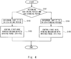
- Fig. 4 is a flowchart showing a flow of a method for controlling the walking training apparatus according to the first embodiment.
- the motion determination unit 351 determines in which of the leg-idling period and the leg-standing period the leg to which the walking assistance apparatus is attached is (step S101).
- the control device 35 performs control, in the leg-idling period, so as to make the motor 331 of the first wire winding mechanism 33 generate a driving force obtained by adding a second driving force for reducing a loss of the pulling force of the first wire winding mechanism 33 caused by the mechanical friction in the first wire winding mechanism 33 to a first driving force.
- the control device 35 performs control, in the leg-idling period, so as to make the motor 331 of the first wire winding mechanism 33 generate a driving force obtained by adding a second driving force for reducing a loss of the pulling force of the first wire winding mechanism 33 caused by the mechanical friction in the first wire winding mechanism 33 to a first driving force.
- control device 35 performs control, in the leg-standing period, so as to make the motor 331 of the first wire winding mechanism 33 generate a driving force obtained by subtracting the second driving force for reducing the loss of the pulling force of the first wire winding mechanism 33 caused by the mechanical friction in the first wire winding mechanism 33 from the first driving force. In this way, it is possible to bring the pulling force of the first wire winding mechanism 33 close to the target pulling force thereof in the leg-standing period, thus enabling the pulling force to be changed smoothly at and near the timing at which the leg-idling period and the leg-standing period are switched from one to the other.
- Fig. 5 shows a schematic configuration of a walking training apparatus according to a second embodiment of the present disclosure.
- the walking training apparatus according to the second embodiment may further include a second wire winding mechanism 38 disposed in the crosswise frame 323 of the frame main body 32.
- the second wire winding mechanism 38 may pull the walking assistance apparatus 2 upward and backward through a wire 39.
- the resultant force of the vertically-upward components of the pulling forces applied by the first and second wire winding mechanisms 33 and 38 supports the weight of the walking assistance apparatus 2. Further, the resultant force of the horizontal components of the pulling forces applied by the first and second wire winding mechanisms 33 and 38 assists the start of swinging of the leg.
- the mechanism control unit 352 controls the driving force of the motor 331 of the first wire winding mechanism 33 by using a first driving force that is determined in advance so as to reduce the gravitational force of the walking assistance apparatus 2 as a base driving force.
- the mechanism control unit 352 controls the driving force of the motor 331 of the second wire winding mechanism 38 by using a third driving force that is determined in advance so as to reduce the gravitational force of the walking assistance apparatus 2 as a base driving force.
- the resultant force of the vertically-upward components of the pulling forces applied by the first and second wire winding mechanisms 33 and 38 reduces the gravitational force of the walking assistance apparatus 2.
- Fig. 6 is a flowchart showing a flow of a method for controlling the walking training apparatus according to the second embodiment.
- the motion determination unit 351 determines in which of the leg-idling period and the leg-standing period the leg to which the walking assistance apparatus is attached is (step S201).
- the first and second embodiments can be combined as desirable by one of ordinary skill in the art.
- a walking training apparatus includes a first wire winding mechanism configured to pull a wire connected to a leg upward and forward, and control means.
- the control means performs at least one of control, in a leg-idling period, so as to make the first wire winding mechanism generate a driving force obtained by adding a second driving force for reducing a loss of the pulling force of the first wire winding mechanism caused by mechanical friction in the first wire winding mechanism to the first driving force, and control, in a leg-standing period, so as to make the first wire winding mechanism generate a driving force obtained by subtracting the second driving force for reducing the loss of the pulling force of the first wire winding mechanism caused by the mechanical friction in the first wire winding mechanism from the first driving force.
Landscapes
- Health & Medical Sciences (AREA)
- General Health & Medical Sciences (AREA)
- Physical Education & Sports Medicine (AREA)
- Life Sciences & Earth Sciences (AREA)
- Public Health (AREA)
- Rehabilitation Therapy (AREA)
- Animal Behavior & Ethology (AREA)
- Pain & Pain Management (AREA)
- Epidemiology (AREA)
- Veterinary Medicine (AREA)
- Orthopedic Medicine & Surgery (AREA)
- Cardiology (AREA)
- Vascular Medicine (AREA)
- Biophysics (AREA)
- Rehabilitation Tools (AREA)
- Manipulator (AREA)
Abstract
Description
- The present disclosure relates to a walking training apparatus by which a trainee does a walking training, and its control method.
- There is a known walking training apparatus that includes: a walking assistance apparatus that assists a walking motion performed by a trainee; a first wire winding mechanism for pulling a wire connected to trainee's leg upward and forward by winding the wire connected to the leg, the first wire winding mechanism being configured to wind and store the wire by rotating a motor in a leg-idling period in which the leg is in an leg-idling state in the walking motion of the trainee and to pay out (i.e., pull out) the wire by rotating the motor in a leg-standing period in which the leg is in a leg-standing state in the walking motion of the trainee; and control means for controlling the pulling force of the first wire winding mechanism and thereby reducing the gravitational force of the walking assistance apparatus (see, for example, Japanese Unexamined Patent Application Publication No.
2015-223294 - The present inventors have found the following problem. In the above-described walking training apparatus, when the first wire winding mechanism winds or pays out (i.e., pulls out) the wire, mechanical friction occurs in the first wire winding mechanism. Because of this mechanical friction, when the first wire winding mechanism winds the wire, the actual pulling force applied by the first wire winding mechanism becomes smaller than the target pulling force by an amount equivalent to this mechanical friction. On the other hand, when the first wire winding mechanism pays out the wire, the actual pulling force applied by the first wire winding mechanism becomes larger than the target pulling force by the amount equivalent to this mechanical friction. As a result, there is a possibility that the pulling force might not smoothly change at or near the timing at which the leg-idling period and the leg-standing period are switched from one to the other.
- The present disclosure has been made in view of the above-described problem and a main object thereof is to provide a walking training apparatus capable of bringing the actual pulling force of the first wire winding mechanism close to the target pulling force thereof in at least one of the leg-idling period and the leg-standing period and thereby enabling the pulling force to be changed smoothly at and near the timing at which the leg-idling period and the leg-standing period are switched from one to the other, and to provide its controlling method.
- To achieve the above-described object, an aspect of the present disclosure is a walking training apparatus including: a walking assistance apparatus configured to be attached to a leg of a trainee and assist a walking motion performed by the trainee; a first wire winding mechanism configured to pull a wire connected to the leg directly or through the walking assistance apparatus upward and forward by winding the wire connected to the leg; and control means for controlling a driving force of a motor of the first wire winding mechanism by using a first driving force as a base driving force, the first driving force being determined in advance so as to reduce a gravitational force of the walking assistance apparatus, in which the first wire winding mechanism winds the wire by rotating the motor in a leg-idling period and pays out the wire by rotating the motor in a direction opposite to the direction in the leg-idling period in a leg-standing period, the leg-idling period being a period in which the leg is in an leg-idling state in the walking motion of the trainee, the leg-standing period being a period in which the leg is in a leg-standing state in the walking motion of the trainee, and in which the control means performs at least one of: control, in the leg-idling period, so as to make the motor of the first wire winding mechanism generate a driving force obtained by adding a second driving force to the first driving force, the second driving force being a force for reducing a loss of the pulling force of the first wire winding mechanism caused by mechanical friction in the first wire winding mechanism; and control, in the leg-standing period, so as to make the motor of the first wire winding mechanism generate a driving force obtained by subtracting the second driving force from the first driving force, the second driving force being the force for reducing the loss of the pulling force of the first wire winding mechanism caused by the mechanical friction in the first wire winding mechanism.
- In this aspect, the walking training apparatus may further include a second wire winding mechanism configured to pull the wire connected to the leg directly or through the walking assistance apparatus upward and backward by winding the wire connected to the leg, in which the second wire winding mechanism may wind the wire by rotating the motor in the leg-idling period and pay out the wire by rotating the motor in the direction opposite to the direction in the leg-idling period in the leg-standing period, the leg-idling period being the period in which the leg is in the leg-idling state in the walking motion of the trainee, the leg-standing period being the period in which the leg is in the leg-standing state in the walking motion of the trainee, and the control means may control a driving force of a motor of the second wire winding mechanism by using a third driving force as a base driving force, the third driving force being determined in advance so as to reduce the gravitational force of the walking assistance apparatus, and in which the control means may perform at least one of: control, in the leg-idling period, so as to make the motor of the second wire winding mechanism generate a driving force obtained by subtracting a fourth driving force from the third driving force, the fourth driving force being a force for reducing a loss of the pulling force of the second wire winding mechanism caused by mechanical friction in the second wire winding mechanism; and control, in the leg-standing period, so as to make the motor of the second wire winding mechanism generate a driving force obtained by adding the fourth driving force to the third driving force, the fourth driving force being the force for reducing the loss of the pulling force of the second wire winding mechanism caused by the mechanical friction in the second wire winding mechanism.
- To achieve the above-described object, an aspect of the present disclosure may be a control method for a walking training apparatus, the walking training apparatus including: a walking assistance apparatus configured to be attached to a leg of a trainee and assist a walking motion performed by the trainee; a first wire winding mechanism configured to pull a wire connected to the leg directly or through the walking assistance apparatus upward and forward by winding the wire connected to the leg; and control means for controlling a driving force of a motor of the first wire winding mechanism by using a first driving force as a base driving force, the first driving force being determined in advance so as to reduce a gravitational force of the walking assistance apparatus, in which the first wire winding mechanism winds the wire by rotating the motor in a leg-idling period and pays out the wire by rotating the motor in a direction opposite to the direction in the leg-idling period in a leg-standing period, the leg-idling period being a period in which the leg is in an leg-idling state in the walking motion of the trainee, the leg-standing period being a period in which the leg is in a leg-standing state in the walking motion of the trainee, and in which the control method includes at least one of: performing control, in the leg-idling period, so as to make the motor of the first wire winding mechanism generate a driving force obtained by adding a second driving force to the first driving force, the second driving force being a force for reducing a loss of the pulling force of the first wire winding mechanism caused by mechanical friction in the first wire winding mechanism; and performing control, in the leg-standing period, so as to make the motor of the first wire winding mechanism generate a driving force obtained by subtracting the second driving force from the first driving force, the second driving force being the force for reducing the loss of the pulling force of the first wire winding mechanism caused by the mechanical friction in the first wire winding mechanism.
- According to the present disclosure, it is possible to provide a walking training apparatus capable of bringing the actual pulling force of the first wire winding mechanism close to the target pulling force thereof in at least one of the leg-idling period and the leg-standing period and thereby enabling the pulling force to be changed smoothly at and near the timing at which the leg-idling period and the leg-standing period are switched from one to the other, and to provide its controlling method.
- The above and other objects, features and advantages of the present invention will become more fully understood from the detailed description given hereinbelow and the accompanying drawings which are given by way of illustration only, and thus are not to be considered as limiting the present invention.
-
-
Fig. 1 is a perspective view showing a schematic configuration of a walking training apparatus according to a first embodiment of the present disclosure; -
Fig. 2 is a perspective view showing a schematic configuration of a walking assistance apparatus; -
Fig. 3 is a block diagram showing an example of a schematic system configuration of a control device according to the first embodiment of the present disclosure; -
Fig. 4 is a flowchart showing a flow of a method for controlling a walking training apparatus according to the first embodiment of the present disclosure; -
Fig. 5 shows a schematic configuration of a walking training apparatus according to a second embodiment of the present disclosure; and -
Fig. 6 is a flowchart showing a flow of a method for controlling a walking training apparatus according to the second embodiment of the present disclosure. - Embodiments according to the present disclosure are explained hereinafter with reference to the drawings.
-
Fig. 1 is a perspective view showing a schematic configuration of a walking training apparatus according to a first embodiment of the present disclosure. A walking training apparatus 1 according to the first embodiment is, for example, an apparatus by which a trainee such as a patient having hemiplegia caused by a stroke does walking training. The walking training apparatus 1 includes awalking assistance apparatus 2 attached to the trainee's leg and a training apparatus 3 by which the trainee does walking training. -
Fig. 2 is a perspective view showing a schematic configuration of the walking assistance apparatus. Thewalking assistance apparatus 2 is, for example, attached to a diseased leg of a trainee who does a walking training and assists walking of the trainee. Thewalking assistance apparatus 2 includes anupper thigh frame 21, alower thigh frame 23 connected to theupper thigh frame 21 through a kneejoint part 22, asole frame 25 connected to thelower thigh frame 23 through an anklejoint part 24, amotor unit 26 that rotationally drives the kneejoint part 22, and anadjustment mechanism 27 that adjusts the movable range of the anklejoint part 24. Note that the above-described configuration of thewalking assistance apparatus 2 is merely an example and the configuration of thewalking assistance apparatus 2 is not limited to such an example. For example, thewalking assistance apparatus 2 may include another motor unit that rotationally drives the anklejoint part 24. - The
upper thigh frame 21 is attached to the upper thigh of the trainee's leg and thelower thigh frame 23 is attached to the lower thigh of the trainee's leg. Theupper thigh frame 21 is, for example, equipped with anupper thigh harness 212 for fixing the upper thigh. Theupper thigh frame 21 is equipped with a horizontally-extending and horizontally-longfirst frame 211 for connecting with awire 36 of a first wire winding mechanism 33 (which is described later). - Note that the above-described connecting part of the first
wire winding mechanism 33 is merely an example and the connection of the firstwire winding mechanism 33 is not limited to such an example. For example, thewire 36 of the firstwire winding mechanism 33 may be connected to theupper thigh harness 212 and the pulling point of the firstwire winding mechanism 33 can be disposed at an arbitrary position in thewalking assistance apparatus 2. - The
motor unit 26 rotationally drives the kneejoint part 22 according to the walking motion of the trainee and thereby assists the walking of the trainee. Note that the above-described configuration of thewalking assistance apparatus 2 is merely an example and the configuration of thewalking assistance apparatus 2 is not limited to such an example. Any walking assistance apparatus capable of being attached to the trainee's leg and assisting walking of the trainee can be applied. - As shown in
Fig. 1 , the training apparatus 3 includes atreadmill 31, a framemain body 32, first and thirdwire winding mechanisms control device 35. Thetreadmill 31 rotates a ring-shaped belt 311. The trainee gets on thebelt 311 and walks on thebelt 311 according to the movement of thebelt 311. By doing so, the trainee does walking training. - The frame
main body 32 includes two pairs ofpillar frames 321 vertically disposed on thetreadmill 31, a pair oflengthwise frames 322 extending in the lengthwise direction and connected torespective pillar frames 321, and threecrosswise frames 323 extending in the crosswise direction and connected to each of thelengthwise frames 322. Note that the configuration of the above-described framemain body 32 is merely an example and is not limited to this example. - In the front
crosswise frame 323, the firstwire winding mechanism 33 that winds thewire 36 connected to the trainee's leg directly or through thewalking assistance apparatus 2 and thereby pulls thewire 36 is provided. One end of thewire 36, which is pulled by the firstwire winding mechanism 33, is connected to thewalking assistance apparatus 2. The firstwire winding mechanism 33 pulls thewalking assistance apparatus 2 upward and forward through thewire 36 by winding thewire 36. - The first
wire winding mechanism 33 includes, for example, a rotor winding/rewinding mechanism for winding thewire 36 around a rotor and paying out (i.e., pulling out) thewire 36 from the rotor, a motor that drives this winding/rewinding mechanism, and so on. The firstwire winding mechanism 33 is configured so as to wind thewire 36 around the rotor and thereby store thewire 36 in a leg-idling period in the walking motion performed by the trainee in which the trainee's leg is in a leg-idling state and pay out (i.e., pull out) thewire 36 from the rotor in a leg-standing period in the walking motion performed by the trainee in which the trainee's leg is in a leg-standing state. - The vertically-upward component of the pulling force applied by the first
wire winding mechanism 33 supports the weight of thewalking assistance apparatus 2. The horizontally-forward component of the pulling force applied by the firstwire winding mechanism 33 assists the start of swinging of the leg. In this way, the walking load of the trainee in the walking training can be reduced. - The third
wire winding mechanism 34 is disposed in the rearcrosswise frame 323 and pulls awire 37 upward. One end of thewire 37 is connected to, for example, a belt attached to at and near the trainee's waist. The thirdwire winding mechanism 34 includes, for example, a mechanism for winding thewire 37 around a rotor and pulling thewire 37 from the rotor, a motor that drives this mechanism, and so on. The thirdwire winding mechanism 34 pulls the trainee's waist upward through thewire 37. In this way, the load on the trainee caused by the weight of the trainee himself/herself can be reduced. Each of the first and thirdwire winding mechanism control device 35 through a wiring line or the like. - The
control device 35 is a specific example of the control means. Thecontrol device 35 controls the pulling forces applied by the first and thirdwire winding mechanisms treadmill 31, and thewalking assistance apparatus 2, respectively. - For example, the
control device 35 is formed by hardware mainly using a microcomputer including a CPU (Central Processing Unit) that performs arithmetic processing, control processing, and so on, a memory including a ROM (Read Only Memory) that stores an arithmetic program, a control program and so on to be executed by the CPU, a RAM (Random Access Memory) and so on, and an interface unit (I/F) that externally receives and outputs signals. The CPU, the memory, and the interface unit are connected with each other through a data bus or the like. - It should be noted that when the first wire winding mechanism winds or pays out the wire, mechanical friction occurs in the first wire winding mechanism. Because of this mechanical friction, when the first wire winding mechanism winds the wire, the actual pulling force applied by the first wire winding mechanism through the wire becomes smaller than the target pulling force by an amount equivalent to a loss caused by this mechanical friction. On the other hand, when the first wire winding mechanism pays out (i.e., pulls out) the wire, the actual pulling force applied by the first wire winding mechanism becomes larger than the target pulling force by an amount equivalent to the loss caused by this mechanical friction. Because of the above-described separation (i.e., difference) between the actual pulling force of the first wire winding mechanism and the target pulling force thereof in the leg-idling period and the leg-standing period, there is a possibility that the pulling force might not smoothly changed at or near the timing at which the leg-idling period and the leg-standing period are switched from one to the other.
- To cope with this problem, in the walking training apparatus 1 according to the first embodiment, the
control device 35 performs control, in the leg-idling period, so as to make the motor of the firstwire winding mechanism 33 generate a driving force obtained by adding a second driving force for reducing the loss of the pulling force of the firstwire winding mechanism 33 caused by the mechanical friction in the firstwire winding mechanism 33 to a first driving force. In this way, it is possible to bring the pulling force of the firstwire winding mechanism 33 close to the target pulling force thereof in the leg-idling period. Therefore, the separation between the actual pulling force of the firstwire winding mechanism 33 and the target pulling force thereof in the leg-idling period can be reduced, thus enabling the pulling force to be changed smoothly at and near the timing at which the leg-idling period and the leg-standing period are switched from one to the other. - Alternatively, the
control device 35 performs control, in the leg-standing period, so as to make the motor of the firstwire winding mechanism 33 generate a driving force obtained by subtracting the second driving force for reducing the loss of the pulling force of the firstwire winding mechanism 33 caused by the mechanical friction in the firstwire winding mechanism 33 from the first driving force. In this way, it is possible to bring the pulling force of the firstwire winding mechanism 33 close to the target pulling force thereof in the leg-standing period. Therefore, the separation between the actual pulling force of the firstwire winding mechanism 33 and the target pulling force thereof in the leg-standing period can be reduced, thus enabling the pulling force to be changed smoothly at and near the timing at which the leg-idling period and the leg-standing period are switched from one to the other. -
Fig. 3 is a block diagram showing an example of a schematic system configuration of the control device according to the first embodiment. Thecontrol device 35 according to the first embodiment incudes amotion determination unit 351 that determines a leg-idling period and a leg-standing period, and amechanism control unit 352 that controls themotor 331 of the firstwire winding mechanism 33 based on a result of the determination by themotion determination unit 351. - The
motion determination unit 351 determines, for example, whether trainee's leg is in a leg-standing state or a leg-idling state based on a load value of trainee's sole that is output from aload sensor 251 disposed in thesole frame 25 of the walkingassistance apparatus 2. Note that when a plurality ofload sensors 251 are arranged in thesole frame 25, for example, an average of load values output from thesesensors 251 may be used as the aforementioned load value. - More specifically, when the load value output from the
load sensor 251 is equal to or larger than a load threshold, themotion determination unit 351 determines that the leg to which thewalking assistance apparatus 2 is attached is in the leg-standing period. On the other hand, when the load value output from theload sensor 251 is smaller than the load threshold, themotion determination unit 351 determines that the leg to which the walking assistance apparatus is attached is in the leg-idling period. In this way, it is possible to easily determine whether the leg is in the leg-standing period or the leg-idling period by using theload sensor 251 disposed in the walking assistance apparatus. - Note that the aforementioned load threshold is obtained by, for example, measuring load values in the state where the leg is in the leg-standing period and those in the state where the leg is in the leg-idling period in advance by using the
load sensor 251, and then the obtained load threshold is set (i.e., stored) in the aforementioned memory or the like. - The
motion determination unit 351 may calculate the center of gravity of the trainee based on a load value(s) output from theload sensor 251 and determine whether the leg is in the leg-standing period or the leg-idling period based on the calculated center of gravity. For example, areas for the center of gravity in the state where the leg is in the leg-standing period and in the state where the leg is in the leg-idling period are obtained in advance. Then, themotion determination unit 351 determines whether the leg is in the leg-standing period or the leg-idling period by determining in which of the above-described obtained areas the center of gravity of the trainee, which is calculated based on the load value output from theload sensor 251, is included. - The
motion determination unit 351 may determine whether the leg to which the walking assistance apparatus is attached is in the leg-standing period or the leg-idling period based on a temporal change (i.e., a change over time) in the angle of the knee joint part of the walking assistance apparatus detected by an angular sensor disposed in the knee joint part. More specifically, themotion determination unit 351 determines that the leg is in the leg-standing period or the leg-idling period when themotion determination unit 351 determines that the detected angle of the knee joint part enters a change area corresponding to the leg-standing period or the leg-idling period based on the temporal change in the angle of the knee joint part detected by the angular sensor. - The
motion determination unit 351 may determine whether the leg to which thewalking assistance apparatus 2 is attached is in the leg-standing period or the leg-idling period based on user's walking cycle calculated from the moving speed of the belt of the treadmill. The relation between the walking cycle and the moving speed of the belt of the treadmill can be experimentally obtained in advance (e.g., the walking cycle is expressed by a monotone decreasing function including the moving speed of the belt of the treadmill as a variable). - The
motion determination unit 351 may determine whether the leg is in the leg-standing period or the leg-idling period based on the amount of thewire 36 stored in the first wire winding mechanism 33 (hereinafter also referred to a "storage amount of wire"). For example, specific storage amounts of thewire 36 in the first wire winding mechanism 33 (such as amounts of winding of the rotor in the first wire winding mechanism 33) in the state where the leg is in the leg-standing period and in the state where the leg is in the leg-idling period are obtained in advance. Then, themotion determination unit 351 may determine whether the leg is in the leg-standing period or the leg-idling period by comparing the obtained specific storage amount with the actual storage amount of thewire 36 in the firstwire winding mechanism 33 detected by a sensor or the like. - Note that the above-described methods for determining the leg-standing period and the leg-idling period are merely examples. That is, the determination method is not limited to the above-described methods and other arbitrary determination methods can be used. The
motion determination unit 351 outputs a result of the above-described determination of the leg-standing period and the leg-idling period to themechanism control unit 352. - Basically, the
mechanism control unit 352 controls the driving force of themotor 331 of the firstwire winding mechanism 33 by using a first driving force that is determined in advance so as to reduce the gravitational force of the walkingassistance apparatus 2 as a base driving force. For example, themechanism control unit 352 controls themotor 331 of the firstwire winding mechanism 33 so that the vertically-upward component of the pulling force applied by the firstwire winding mechanism 33 becomes equal to the gravitational force of the walkingassistance apparatus 2. As a result, the load on the walking of the trainee exerted by the gravitational force of the walkingassistance apparatus 2 can be reduced. - Further, in response to a determination result that the leg is in the leg-idling period output from the
motion determination unit 351, themechanism control unit 352 performs control so as to make themotor 331 of the firstwire winding mechanism 33 generate a driving force obtained by adding a second driving force for reducing a loss of the pulling force of the firstwire winding mechanism 33 caused by mechanical friction in the firstwire winding mechanism 33 to the first driving force. - Note that the mechanical friction in the first
wire winding mechanism 33 means, for example, dynamical friction and/or viscous friction of the rotor winding/rewinding mechanism, themotor 331, and/or the like of the firstwire winding mechanism 33. - For example, the
mechanism control unit 352 calculates a mechanical friction force FT based on the below-shown expression. Then, themechanism control unit 352 calculates a second friction force f2 corresponding to the calculated mechanical friction force FT by multiplying the mechanical friction force FT by a predetermined coefficient. Note that examples of the second friction force f2 corresponding to the mechanical friction force FT may include not only a second friction force f2 equal to the mechanical friction force FT, but also a second friction force f2 for reducing a loss of the pulling force of the firstwire winding mechanism 33 that is smaller or larger than the second friction force f2 equal to the mechanical friction force FT.
- In the above-shown expression, Tdynamic is a dynamical friction force and Kfθv is a viscous friction force. Further, Kf is a viscous friction coefficient and θv is a rotation speed of the
motor 331 or the rotor. - In response to a determination result that the leg is in the leg-idling period by the
motion determination unit 351, themechanism control unit 352 performs control so as to make themotor 331 of the firstwire winding mechanism 33 generate a driving force f(f=f1+f2) obtained by adding the above-described calculated second driving force f2 to the first driving force f2. - In response to a determination result that the leg is in the leg-standing period output from the
motion determination unit 351, themechanism control unit 352 performs control so as to make themotor 331 of the firstwire winding mechanism 33 generate a driving force obtained by subtracting a second driving force for reducing a loss of the pulling force of the firstwire winding mechanism 33 caused by mechanical friction in the firstwire winding mechanism 33 from the first driving force. The second driving force in the leg-standing period can be calculated in a manner similar to that for the above-described calculation for the second driving force in the leg-idling period. - Note that the
control device 35 may perform control so as to make themotor 331 of the firstwire winding mechanism 33 generate a driving force obtained by adding the second driving force to the first driving force in the leg-idling period, and perform control so as to make themotor 331 of the firstwire winding mechanism 33 generate a driving force obtained by subtracting the second driving force from the first driving force in the leg-standing period. In this way, it is possible to bring the pulling force of the firstwire winding mechanism 33 close to the target pulling force thereof in the leg-idling period and the leg-standing period. As a result, it is possible to change the pulling force more smoothly at and near the timing at which the leg-idling period and the leg-standing period are switched from one to the other. -
Fig. 4 is a flowchart showing a flow of a method for controlling the walking training apparatus according to the first embodiment. Themotion determination unit 351 determines in which of the leg-idling period and the leg-standing period the leg to which the walking assistance apparatus is attached is (step S101). - When the
motion determination unit 351 determines that the leg to which the walking assistance apparatus is attached is in the leg-idling period (step S102), in response to this determination result that the leg is in the leg-idling period, themechanism control unit 352 performs control so as to make themotor 331 of the firstwire winding mechanism 33 generate a driving force ff (ff=ff1+ff2) obtained by adding a second driving force ff2 for reducing a loss of the pulling force of the firstwire winding mechanism 33 caused by mechanical friction in the firstwire winding mechanism 33 to a first driving force ff1 (step S103). - On the other hand, when the
motion determination unit 351 determines that the leg to which the walking assistance apparatus is attached is in the leg-standing period (step S104), in response to this determination result that the leg is in the leg-standing period, themechanism control unit 352 performs control so as to make themotor 331 of the firstwire winding mechanism 33 generate a driving force ff(ff=ff1-ff2) obtained by subtracting the second driving force ff2 from the first driving force ff1 (step S105). - As explained above, in the first embodiment, the
control device 35 performs control, in the leg-idling period, so as to make themotor 331 of the firstwire winding mechanism 33 generate a driving force obtained by adding a second driving force for reducing a loss of the pulling force of the firstwire winding mechanism 33 caused by the mechanical friction in the firstwire winding mechanism 33 to a first driving force. In this way, it is possible to bring the pulling force of the firstwire winding mechanism 33 close to the target pulling force thereof in the leg-idling period, thus enabling the pulling force to be changed smoothly at and near the timing at which the leg-idling period and the leg-standing period are switched from one to the other. - Further, the
control device 35 performs control, in the leg-standing period, so as to make themotor 331 of the firstwire winding mechanism 33 generate a driving force obtained by subtracting the second driving force for reducing the loss of the pulling force of the firstwire winding mechanism 33 caused by the mechanical friction in the firstwire winding mechanism 33 from the first driving force. In this way, it is possible to bring the pulling force of the firstwire winding mechanism 33 close to the target pulling force thereof in the leg-standing period, thus enabling the pulling force to be changed smoothly at and near the timing at which the leg-idling period and the leg-standing period are switched from one to the other. -
Fig. 5 shows a schematic configuration of a walking training apparatus according to a second embodiment of the present disclosure. The walking training apparatus according to the second embodiment may further include a secondwire winding mechanism 38 disposed in thecrosswise frame 323 of the framemain body 32. The secondwire winding mechanism 38 may pull thewalking assistance apparatus 2 upward and backward through awire 39. The resultant force of the vertically-upward components of the pulling forces applied by the first and secondwire winding mechanisms assistance apparatus 2. Further, the resultant force of the horizontal components of the pulling forces applied by the first and secondwire winding mechanisms - The
mechanism control unit 352 controls the driving force of themotor 331 of the firstwire winding mechanism 33 by using a first driving force that is determined in advance so as to reduce the gravitational force of the walkingassistance apparatus 2 as a base driving force. At the same time, themechanism control unit 352 controls the driving force of themotor 331 of the secondwire winding mechanism 38 by using a third driving force that is determined in advance so as to reduce the gravitational force of the walkingassistance apparatus 2 as a base driving force. Further, the resultant force of the vertically-upward components of the pulling forces applied by the first and secondwire winding mechanisms assistance apparatus 2. In this way, the vertically-upward components and the horizontally-forward components of the pulling forces applied by the first and secondwire winding mechanisms assistance apparatus 2, reduce the load exerted on the leg to which thewalking assistance apparatus 2 is attached at the start of swinging of the leg more optimally. Note that the other configuration of the second embodiment is roughly identical to that of the above-described first embodiment. Therefore, the same symbols are assigned to the same components and their detailed explanations are omitted. -
Fig. 6 is a flowchart showing a flow of a method for controlling the walking training apparatus according to the second embodiment. - The
motion determination unit 351 determines in which of the leg-idling period and the leg-standing period the leg to which the walking assistance apparatus is attached is (step S201). - When the
motion determination unit 351 determines that the leg to which the walking assistance apparatus is attached is in the leg-idling period (step S202), in response to a result of this determination that the leg is in the leg-idling period, themechanism control unit 352 performs control so as to make themotor 331 of the firstwire winding mechanism 33 generate a driving force ff (ff=ff1+ff2) obtained by adding a second driving force ff2 for reducing a loss of the pulling force of the firstwire winding mechanism 33 caused by mechanical friction in the firstwire winding mechanism 33 to a first driving force ff1 (step S203). At the same time, in response to the result of the determination that the leg is in the leg-idling period, themechanism control unit 352 performs control so as to make themotor 331 of the secondwire winding mechanism 38 generate a driving force fr (fr=fr1-fr2) obtained by subtracting a fourth driving force fr2 for reducing a loss of the pulling force of the secondwire winding mechanism 38 caused by mechanical friction in the secondwire winding mechanism 38 from a third driving force fr1 (step S204). - On the other hand, when the
motion determination unit 351 determines that the leg to which the walking assistance apparatus is attached is in the leg-standing period (step S205), in response to a result of this determination that the leg is in the leg-standing period, themechanism control unit 352 performs control so as to make themotor 331 of the firstwire winding mechanism 33 generate a driving force ff (ff=ff1-ff2) obtained by subtracting the second driving force ff2 from the first driving force ff1 (step S206). At the same time, in response to the result of the determination that the leg is in the leg-standing period, themechanism control unit 352 performs control so as to make themotor 331 of the secondwire winding mechanism 38 generate a driving force fr (fr=fr1+fr2) obtained by adding the fourth driving force fr2 to the third driving force fr1 (step S207). - Note that the present disclosure is not limited to the above-described embodiments, and various modifications can be made without departing from the spirit and scope of the present disclosure.
- The first and second embodiments can be combined as desirable by one of ordinary skill in the art.
- From the invention thus described, it will be obvious that the embodiments of the invention may be varied in many ways. Such variations are not to be regarded as a departure from the spirit and scope of the invention, and all such modifications as would be obvious to one skilled in the art are intended for inclusion within the scope of the following claims.
- A walking training apparatus includes a first wire winding mechanism configured to pull a wire connected to a leg upward and forward, and control means. The control means performs at least one of control, in a leg-idling period, so as to make the first wire winding mechanism generate a driving force obtained by adding a second driving force for reducing a loss of the pulling force of the first wire winding mechanism caused by mechanical friction in the first wire winding mechanism to the first driving force, and control, in a leg-standing period, so as to make the first wire winding mechanism generate a driving force obtained by subtracting the second driving force for reducing the loss of the pulling force of the first wire winding mechanism caused by the mechanical friction in the first wire winding mechanism from the first driving force.
Claims (3)
- A walking training apparatus (1) comprising:a walking assistance apparatus (2) configured to be attached to a leg of a trainee and assist a walking motion performed by the trainee;a first wire winding mechanism (33) configured to pull a wire (36) connected to the leg directly or through the walking assistance apparatus (2) upward and forward by winding the wire (36) connected to the leg; andcontrol means (35) for controlling a driving force of a motor of the first wire winding mechanism (33) by using a first driving force as a base driving force, the first driving force being determined in advance so as to reduce a gravitational force of the walking assistance apparatus (2),wherein the first wire winding mechanism (33) winds the wire (36) by rotating the motor in a leg-idling period and pays out the wire (36) by rotating the motor in a direction opposite to the direction in the leg-idling period in a leg-standing period, the leg-idling period being a period in which the leg is in an leg-idling state in the walking motion of the trainee, the leg-standing period being a period in which the leg is in a leg-standing state in the walking motion of the trainee, andwherein the control means (35) performs at least one of:control, in the leg-idling period, so as to make the motor of the first wire winding mechanism (33) generate a driving force obtained by adding a second driving force to the first driving force, the second driving force being a force for reducing a loss of the pulling force of the first wire winding mechanism (33) caused by mechanical friction in the first wire winding mechanism (33); andcontrol, in the leg-standing period, so as to make the motor of the first wire winding mechanism (33) generate a driving force obtained by subtracting the second driving force from the first driving force, the second driving force being the force for reducing the loss of the pulling force of the first wire winding mechanism (33) caused by the mechanical friction in the first wire winding mechanism (33).
- The walking training apparatus (1) according to Claim 1, further comprising a second wire winding mechanism (38) configured to pull the wire (39) connected to the leg directly or through the walking assistance apparatus (2) upward and backward by winding the wire (39) connected to the leg,
wherein the second wire winding mechanism (38) winds the wire (39) by rotating the motor in the leg-idling period and pays out the wire (39) by rotating the motor in the direction opposite to the direction in the leg-idling period in the leg-standing period, the leg-idling period being the period in which the leg is in the leg-idling state in the walking motion of the trainee, the leg-standing period being the period in which the leg is in the leg-standing state in the walking motion of the trainee, and
the control means (35) controls a driving force of a motor of the second wire winding mechanism (38) by using a third driving force as a base driving force, the third driving force being determined in advance so as to reduce the gravitational force of the walking assistance apparatus (2), and
wherein the control means (35) performs at least one of:control, in the leg-idling period, so as to make the motor of the second wire winding mechanism (38) generate a driving force obtained by subtracting a fourth driving force from the third driving force, the fourth driving force being a force for reducing a loss of the pulling force of the second wire winding mechanism (38) caused by mechanical friction in the second wire winding mechanism (38); andcontrol, in the leg-standing period, so as to make the motor of the second wire winding mechanism (38) generate a driving force obtained by adding the fourth driving force to the third driving force, the fourth driving force being the force for reducing the loss of the pulling force of the second wire winding mechanism (38) caused by the mechanical friction in the second wire winding mechanism (38). - A control method for a walking training apparatus (1), the walking training apparatus (1) comprising:a walking assistance apparatus (2) configured to be attached to a leg of a trainee and assist a walking motion performed by the trainee;a first wire winding mechanism (33) configured to pull a wire (36) connected to the leg directly or through the walking assistance apparatus (2) upward and forward by winding the wire (36) connected to the leg; andcontrol means (35) for controlling a driving force of a motor of the first wire winding mechanism (33) by using a first driving force as a base driving force, the first driving force being determined in advance so as to reduce a gravitational force of the walking assistance apparatus (2),wherein the first wire winding mechanism (33) winds the wire (36) by rotating the motor in a leg-idling period and pays out the wire (36) by rotating the motor in a direction opposite to the direction in the leg-idling period in a leg-standing period, the leg-idling period being a period in which the leg is in an leg-idling state in the walking motion of the trainee, the leg-standing period being a period in which the leg is in a leg-standing state in the walking motion of the trainee, andwherein the control method comprises at least one of:performing control, in the leg-idling period, so as to make the motor of the first wire winding mechanism (33) generate a driving force obtained by adding a second driving force to the first driving force, the second driving force being a force for reducing a loss of the pulling force of the first wire winding mechanism (33) caused by mechanical friction in the first wire winding mechanism (33); andperforming control, in the leg-standing period, so as to make the motor of the first wire winding mechanism (33) generate a driving force obtained by subtracting the second driving force from the first driving force, the second driving force being the force for reducing the loss of the pulling force of the first wire winding mechanism (33) caused by the mechanical friction in the first wire winding mechanism (33).
Applications Claiming Priority (1)
| Application Number | Priority Date | Filing Date | Title |
|---|---|---|---|
| JP2016190292A JP6477644B2 (en) | 2016-09-28 | 2016-09-28 | Walking training apparatus and control method thereof |
Publications (2)
| Publication Number | Publication Date |
|---|---|
| EP3300710A1 true EP3300710A1 (en) | 2018-04-04 |
| EP3300710B1 EP3300710B1 (en) | 2021-05-26 |
Family
ID=59713881
Family Applications (1)
| Application Number | Title | Priority Date | Filing Date |
|---|---|---|---|
| EP17187885.3A Active EP3300710B1 (en) | 2016-09-28 | 2017-08-25 | Walking training apparatus and its control method |
Country Status (4)
| Country | Link |
|---|---|
| US (1) | US20180085278A1 (en) |
| EP (1) | EP3300710B1 (en) |
| JP (1) | JP6477644B2 (en) |
| CN (1) | CN107865752B (en) |
Families Citing this family (8)
| Publication number | Priority date | Publication date | Assignee | Title |
|---|---|---|---|---|
| WO2016033024A1 (en) * | 2014-08-25 | 2016-03-03 | The Uab Research Foundation | System and method for performing exercise testing and training |
| JP6958374B2 (en) * | 2018-01-18 | 2021-11-02 | トヨタ自動車株式会社 | Walking training device and its control method |
| IT201800003889A1 (en) * | 2018-03-23 | 2018-06-23 | Nimble Robotics S R L | Gait rehabilitation system and weight support device for this system |
| JP7548129B2 (en) * | 2021-06-03 | 2024-09-10 | トヨタ自動車株式会社 | Gait training system, control method thereof, and control program |
| JP7512958B2 (en) * | 2021-06-15 | 2024-07-09 | トヨタ自動車株式会社 | Walking Training System |
| KR102737115B1 (en) * | 2021-08-11 | 2024-12-03 | 주식회사 알피오 | Active walking assistance robot for rehabilitation training |
| KR102577401B1 (en) * | 2021-09-27 | 2023-09-12 | 안왕근 | Rehabilitation equipment for spine and knee |
| CN117839169A (en) * | 2024-01-26 | 2024-04-09 | 河南翔宇医疗设备股份有限公司 | An automatic assisted standing and sitting training system for rehabilitation patients |
Citations (5)
| Publication number | Priority date | Publication date | Assignee | Title |
|---|---|---|---|---|
| US20130158444A1 (en) * | 2011-12-20 | 2013-06-20 | Massachusetts Institute Of Technology | Robotic System for Simulating a Wearable Device and Method of Use |
| WO2015164421A1 (en) * | 2014-04-21 | 2015-10-29 | The Trustees Of Columbia University In The City Of New York | Human movement research, therapeutic, and diagnostic devices, methods, and systems |
| EP2949366A1 (en) * | 2014-05-27 | 2015-12-02 | Toyota Jidosha Kabushiki Kaisha | Walking training system and walking training method of the same |
| JP2015223294A (en) | 2014-05-27 | 2015-12-14 | トヨタ自動車株式会社 | Walking training apparatus and walking training method thereof |
| EP2990084A1 (en) * | 2014-08-25 | 2016-03-02 | Toyota Jidosha Kabushiki Kaisha | Gait training apparatus and control method therefor |
Family Cites Families (14)
| Publication number | Priority date | Publication date | Assignee | Title |
|---|---|---|---|---|
| TW452080U (en) * | 2000-09-27 | 2001-08-21 | Hycom Instr Corp | Water quality monitoring device for automatic water level tracking |
| JP3888310B2 (en) * | 2003-02-06 | 2007-02-28 | トヨタ自動車株式会社 | Data creation device for walking robot control and ZMP position calculation method |
| JP2005205001A (en) * | 2004-01-23 | 2005-08-04 | Yaskawa Electric Corp | Leg swing-out assist mechanism, movement assist device equipped with the same, and movement assist device with saddle |
| JP4712620B2 (en) * | 2006-06-12 | 2011-06-29 | 本田技研工業株式会社 | Control device for walking aids |
| US9216131B2 (en) * | 2009-11-13 | 2015-12-22 | Toyota Jidosha Kabushiki Kaisha | Walking assist device |
| CN201624946U (en) * | 2010-01-18 | 2010-11-10 | 梁汉基 | Spine rehabilitation healthcare massage bed |
| US20140058299A1 (en) * | 2011-03-02 | 2014-02-27 | Yoshiyuki Sankai | Gait training device and gait training system |
| WO2013022833A1 (en) * | 2011-08-05 | 2013-02-14 | Ohio University | Motorized drive system and method for articulating a joint |
| CN203107591U (en) * | 2012-12-27 | 2013-08-07 | 张家港市永发机器人科技有限公司 | Arm rehabilitation training device |
| CN103315881A (en) * | 2013-06-26 | 2013-09-25 | 浙江大学 | Exoskeleton flexible joint drive device based on flexible rope transmission |
| CN103845184B (en) * | 2014-01-26 | 2016-01-13 | 清华大学 | The dermaskeleton type upper limb rehabilitation robot system that a kind of rope drives |
| JP6308108B2 (en) * | 2014-11-17 | 2018-04-11 | トヨタ自動車株式会社 | Walking training system |
| CN104800040B (en) * | 2015-03-06 | 2016-08-24 | 合肥工业大学 | A kind of waist rehabilitation training devices's dynamic characteristic detection apparatus and method in parallel |
| CN105411811A (en) * | 2015-10-28 | 2016-03-23 | 西安电子科技大学 | Modularized multifunctional rehabilitation training device |
-
2016
- 2016-09-28 JP JP2016190292A patent/JP6477644B2/en active Active
-
2017
- 2017-08-22 US US15/682,598 patent/US20180085278A1/en not_active Abandoned
- 2017-08-25 EP EP17187885.3A patent/EP3300710B1/en active Active
- 2017-09-26 CN CN201710881589.4A patent/CN107865752B/en not_active Expired - Fee Related
Patent Citations (5)
| Publication number | Priority date | Publication date | Assignee | Title |
|---|---|---|---|---|
| US20130158444A1 (en) * | 2011-12-20 | 2013-06-20 | Massachusetts Institute Of Technology | Robotic System for Simulating a Wearable Device and Method of Use |
| WO2015164421A1 (en) * | 2014-04-21 | 2015-10-29 | The Trustees Of Columbia University In The City Of New York | Human movement research, therapeutic, and diagnostic devices, methods, and systems |
| EP2949366A1 (en) * | 2014-05-27 | 2015-12-02 | Toyota Jidosha Kabushiki Kaisha | Walking training system and walking training method of the same |
| JP2015223294A (en) | 2014-05-27 | 2015-12-14 | トヨタ自動車株式会社 | Walking training apparatus and walking training method thereof |
| EP2990084A1 (en) * | 2014-08-25 | 2016-03-02 | Toyota Jidosha Kabushiki Kaisha | Gait training apparatus and control method therefor |
Also Published As
| Publication number | Publication date |
|---|---|
| CN107865752A (en) | 2018-04-03 |
| CN107865752B (en) | 2020-03-17 |
| US20180085278A1 (en) | 2018-03-29 |
| JP6477644B2 (en) | 2019-03-06 |
| JP2018050945A (en) | 2018-04-05 |
| EP3300710B1 (en) | 2021-05-26 |
Similar Documents
| Publication | Publication Date | Title |
|---|---|---|
| EP3300710A1 (en) | Walking training apparatus and its control method | |
| EP3127527B1 (en) | Walking training apparatus | |
| US10251804B2 (en) | Walking training apparatus and walking training method therefor | |
| US10874576B2 (en) | Gait state determination apparatus, gait state determination method, and walking training apparatus | |
| US20180085280A1 (en) | Walking assistance apparatus and its control method | |
| EP2949365B1 (en) | Walk training apparatus and walk training method thereof | |
| US20190216669A1 (en) | Walking training apparatus and control method thereof | |
| EP2949366A1 (en) | Walking training system and walking training method of the same | |
| KR20160043710A (en) | Method and apparatus for conrolling walking assist | |
| JP6248818B2 (en) | Walking training device | |
| JP6926914B2 (en) | Walking training system and its control method | |
| JP6645253B2 (en) | Walking training device and its control method | |
| EP4257105B1 (en) | Method and device for adjusting value of control parameter of wearable device | |
| EP4335427B1 (en) | Non-therapeutic method and apparatus for outputting torque to provide force to user | |
| JP6443301B2 (en) | Walking training device | |
| JP6958205B2 (en) | Walking training system | |
| JP6953977B2 (en) | Walking training system |
Legal Events
| Date | Code | Title | Description |
|---|---|---|---|
| PUAI | Public reference made under article 153(3) epc to a published international application that has entered the european phase |
Free format text: ORIGINAL CODE: 0009012 |
|
| STAA | Information on the status of an ep patent application or granted ep patent |
Free format text: STATUS: REQUEST FOR EXAMINATION WAS MADE |
|
| 17P | Request for examination filed |
Effective date: 20170825 |
|
| AK | Designated contracting states |
Kind code of ref document: A1 Designated state(s): AL AT BE BG CH CY CZ DE DK EE ES FI FR GB GR HR HU IE IS IT LI LT LU LV MC MK MT NL NO PL PT RO RS SE SI SK SM TR |
|
| AX | Request for extension of the european patent |
Extension state: BA ME |
|
| STAA | Information on the status of an ep patent application or granted ep patent |
Free format text: STATUS: EXAMINATION IS IN PROGRESS |
|
| 17Q | First examination report despatched |
Effective date: 20200421 |
|
| GRAP | Despatch of communication of intention to grant a patent |
Free format text: ORIGINAL CODE: EPIDOSNIGR1 |
|
| STAA | Information on the status of an ep patent application or granted ep patent |
Free format text: STATUS: GRANT OF PATENT IS INTENDED |
|
| INTG | Intention to grant announced |
Effective date: 20210203 |
|
| GRAS | Grant fee paid |
Free format text: ORIGINAL CODE: EPIDOSNIGR3 |
|
| GRAA | (expected) grant |
Free format text: ORIGINAL CODE: 0009210 |
|
| STAA | Information on the status of an ep patent application or granted ep patent |
Free format text: STATUS: THE PATENT HAS BEEN GRANTED |
|
| AK | Designated contracting states |
Kind code of ref document: B1 Designated state(s): AL AT BE BG CH CY CZ DE DK EE ES FI FR GB GR HR HU IE IS IT LI LT LU LV MC MK MT NL NO PL PT RO RS SE SI SK SM TR |
|
| REG | Reference to a national code |
Ref country code: GB Ref legal event code: FG4D |
|
| REG | Reference to a national code |
Ref country code: CH Ref legal event code: EP |
|
| REG | Reference to a national code |
Ref country code: AT Ref legal event code: REF Ref document number: 1395480 Country of ref document: AT Kind code of ref document: T Effective date: 20210615 |
|
| REG | Reference to a national code |
Ref country code: DE Ref legal event code: R096 Ref document number: 602017039153 Country of ref document: DE |
|
| REG | Reference to a national code |
Ref country code: IE Ref legal event code: FG4D |
|
| REG | Reference to a national code |
Ref country code: LT Ref legal event code: MG9D |
|
| REG | Reference to a national code |
Ref country code: AT Ref legal event code: MK05 Ref document number: 1395480 Country of ref document: AT Kind code of ref document: T Effective date: 20210526 |
|
| PG25 | Lapsed in a contracting state [announced via postgrant information from national office to epo] |
Ref country code: HR Free format text: LAPSE BECAUSE OF FAILURE TO SUBMIT A TRANSLATION OF THE DESCRIPTION OR TO PAY THE FEE WITHIN THE PRESCRIBED TIME-LIMIT Effective date: 20210526 Ref country code: BG Free format text: LAPSE BECAUSE OF FAILURE TO SUBMIT A TRANSLATION OF THE DESCRIPTION OR TO PAY THE FEE WITHIN THE PRESCRIBED TIME-LIMIT Effective date: 20210826 Ref country code: AT Free format text: LAPSE BECAUSE OF FAILURE TO SUBMIT A TRANSLATION OF THE DESCRIPTION OR TO PAY THE FEE WITHIN THE PRESCRIBED TIME-LIMIT Effective date: 20210526 Ref country code: FI Free format text: LAPSE BECAUSE OF FAILURE TO SUBMIT A TRANSLATION OF THE DESCRIPTION OR TO PAY THE FEE WITHIN THE PRESCRIBED TIME-LIMIT Effective date: 20210526 Ref country code: LT Free format text: LAPSE BECAUSE OF FAILURE TO SUBMIT A TRANSLATION OF THE DESCRIPTION OR TO PAY THE FEE WITHIN THE PRESCRIBED TIME-LIMIT Effective date: 20210526 |
|
| REG | Reference to a national code |
Ref country code: NL Ref legal event code: MP Effective date: 20210526 |
|
| PG25 | Lapsed in a contracting state [announced via postgrant information from national office to epo] |
Ref country code: PL Free format text: LAPSE BECAUSE OF FAILURE TO SUBMIT A TRANSLATION OF THE DESCRIPTION OR TO PAY THE FEE WITHIN THE PRESCRIBED TIME-LIMIT Effective date: 20210526 Ref country code: NO Free format text: LAPSE BECAUSE OF FAILURE TO SUBMIT A TRANSLATION OF THE DESCRIPTION OR TO PAY THE FEE WITHIN THE PRESCRIBED TIME-LIMIT Effective date: 20210826 Ref country code: PT Free format text: LAPSE BECAUSE OF FAILURE TO SUBMIT A TRANSLATION OF THE DESCRIPTION OR TO PAY THE FEE WITHIN THE PRESCRIBED TIME-LIMIT Effective date: 20210927 Ref country code: RS Free format text: LAPSE BECAUSE OF FAILURE TO SUBMIT A TRANSLATION OF THE DESCRIPTION OR TO PAY THE FEE WITHIN THE PRESCRIBED TIME-LIMIT Effective date: 20210526 Ref country code: SE Free format text: LAPSE BECAUSE OF FAILURE TO SUBMIT A TRANSLATION OF THE DESCRIPTION OR TO PAY THE FEE WITHIN THE PRESCRIBED TIME-LIMIT Effective date: 20210526 Ref country code: LV Free format text: LAPSE BECAUSE OF FAILURE TO SUBMIT A TRANSLATION OF THE DESCRIPTION OR TO PAY THE FEE WITHIN THE PRESCRIBED TIME-LIMIT Effective date: 20210526 Ref country code: IS Free format text: LAPSE BECAUSE OF FAILURE TO SUBMIT A TRANSLATION OF THE DESCRIPTION OR TO PAY THE FEE WITHIN THE PRESCRIBED TIME-LIMIT Effective date: 20210926 Ref country code: GR Free format text: LAPSE BECAUSE OF FAILURE TO SUBMIT A TRANSLATION OF THE DESCRIPTION OR TO PAY THE FEE WITHIN THE PRESCRIBED TIME-LIMIT Effective date: 20210827 |
|
| PG25 | Lapsed in a contracting state [announced via postgrant information from national office to epo] |
Ref country code: NL Free format text: LAPSE BECAUSE OF FAILURE TO SUBMIT A TRANSLATION OF THE DESCRIPTION OR TO PAY THE FEE WITHIN THE PRESCRIBED TIME-LIMIT Effective date: 20210526 |
|
| PG25 | Lapsed in a contracting state [announced via postgrant information from national office to epo] |
Ref country code: SK Free format text: LAPSE BECAUSE OF FAILURE TO SUBMIT A TRANSLATION OF THE DESCRIPTION OR TO PAY THE FEE WITHIN THE PRESCRIBED TIME-LIMIT Effective date: 20210526 Ref country code: SM Free format text: LAPSE BECAUSE OF FAILURE TO SUBMIT A TRANSLATION OF THE DESCRIPTION OR TO PAY THE FEE WITHIN THE PRESCRIBED TIME-LIMIT Effective date: 20210526 Ref country code: ES Free format text: LAPSE BECAUSE OF FAILURE TO SUBMIT A TRANSLATION OF THE DESCRIPTION OR TO PAY THE FEE WITHIN THE PRESCRIBED TIME-LIMIT Effective date: 20210526 Ref country code: RO Free format text: LAPSE BECAUSE OF FAILURE TO SUBMIT A TRANSLATION OF THE DESCRIPTION OR TO PAY THE FEE WITHIN THE PRESCRIBED TIME-LIMIT Effective date: 20210526 Ref country code: DK Free format text: LAPSE BECAUSE OF FAILURE TO SUBMIT A TRANSLATION OF THE DESCRIPTION OR TO PAY THE FEE WITHIN THE PRESCRIBED TIME-LIMIT Effective date: 20210526 Ref country code: CZ Free format text: LAPSE BECAUSE OF FAILURE TO SUBMIT A TRANSLATION OF THE DESCRIPTION OR TO PAY THE FEE WITHIN THE PRESCRIBED TIME-LIMIT Effective date: 20210526 Ref country code: EE Free format text: LAPSE BECAUSE OF FAILURE TO SUBMIT A TRANSLATION OF THE DESCRIPTION OR TO PAY THE FEE WITHIN THE PRESCRIBED TIME-LIMIT Effective date: 20210526 |
|
| REG | Reference to a national code |
Ref country code: DE Ref legal event code: R097 Ref document number: 602017039153 Country of ref document: DE |
|
| REG | Reference to a national code |
Ref country code: CH Ref legal event code: PL |
|
| PLBE | No opposition filed within time limit |
Free format text: ORIGINAL CODE: 0009261 |
|
| STAA | Information on the status of an ep patent application or granted ep patent |
Free format text: STATUS: NO OPPOSITION FILED WITHIN TIME LIMIT |
|
| PG25 | Lapsed in a contracting state [announced via postgrant information from national office to epo] |
Ref country code: MC Free format text: LAPSE BECAUSE OF FAILURE TO SUBMIT A TRANSLATION OF THE DESCRIPTION OR TO PAY THE FEE WITHIN THE PRESCRIBED TIME-LIMIT Effective date: 20210526 |
|
| REG | Reference to a national code |
Ref country code: BE Ref legal event code: MM Effective date: 20210831 |
|
| PG25 | Lapsed in a contracting state [announced via postgrant information from national office to epo] |
Ref country code: LI Free format text: LAPSE BECAUSE OF NON-PAYMENT OF DUE FEES Effective date: 20210831 Ref country code: CH Free format text: LAPSE BECAUSE OF NON-PAYMENT OF DUE FEES Effective date: 20210831 |
|
| 26N | No opposition filed |
Effective date: 20220301 |
|
| PG25 | Lapsed in a contracting state [announced via postgrant information from national office to epo] |
Ref country code: IS Free format text: LAPSE BECAUSE OF FAILURE TO SUBMIT A TRANSLATION OF THE DESCRIPTION OR TO PAY THE FEE WITHIN THE PRESCRIBED TIME-LIMIT Effective date: 20210926 Ref country code: LU Free format text: LAPSE BECAUSE OF NON-PAYMENT OF DUE FEES Effective date: 20210825 Ref country code: AL Free format text: LAPSE BECAUSE OF FAILURE TO SUBMIT A TRANSLATION OF THE DESCRIPTION OR TO PAY THE FEE WITHIN THE PRESCRIBED TIME-LIMIT Effective date: 20210526 |
|
| PG25 | Lapsed in a contracting state [announced via postgrant information from national office to epo] |
Ref country code: IT Free format text: LAPSE BECAUSE OF FAILURE TO SUBMIT A TRANSLATION OF THE DESCRIPTION OR TO PAY THE FEE WITHIN THE PRESCRIBED TIME-LIMIT Effective date: 20210526 Ref country code: IE Free format text: LAPSE BECAUSE OF NON-PAYMENT OF DUE FEES Effective date: 20210825 Ref country code: BE Free format text: LAPSE BECAUSE OF NON-PAYMENT OF DUE FEES Effective date: 20210831 |
|
| PGFP | Annual fee paid to national office [announced via postgrant information from national office to epo] |
Ref country code: GB Payment date: 20220707 Year of fee payment: 6 Ref country code: DE Payment date: 20220705 Year of fee payment: 6 |
|
| PGFP | Annual fee paid to national office [announced via postgrant information from national office to epo] |
Ref country code: FR Payment date: 20220709 Year of fee payment: 6 |
|
| PG25 | Lapsed in a contracting state [announced via postgrant information from national office to epo] |
Ref country code: HU Free format text: LAPSE BECAUSE OF FAILURE TO SUBMIT A TRANSLATION OF THE DESCRIPTION OR TO PAY THE FEE WITHIN THE PRESCRIBED TIME-LIMIT; INVALID AB INITIO Effective date: 20170825 |
|
| P01 | Opt-out of the competence of the unified patent court (upc) registered |
Effective date: 20230427 |
|
| PG25 | Lapsed in a contracting state [announced via postgrant information from national office to epo] |
Ref country code: CY Free format text: LAPSE BECAUSE OF FAILURE TO SUBMIT A TRANSLATION OF THE DESCRIPTION OR TO PAY THE FEE WITHIN THE PRESCRIBED TIME-LIMIT Effective date: 20210526 |
|
| REG | Reference to a national code |
Ref country code: DE Ref legal event code: R119 Ref document number: 602017039153 Country of ref document: DE |
|
| GBPC | Gb: european patent ceased through non-payment of renewal fee |
Effective date: 20230825 |
|
| PG25 | Lapsed in a contracting state [announced via postgrant information from national office to epo] |
Ref country code: MK Free format text: LAPSE BECAUSE OF FAILURE TO SUBMIT A TRANSLATION OF THE DESCRIPTION OR TO PAY THE FEE WITHIN THE PRESCRIBED TIME-LIMIT Effective date: 20210526 |
|
| PG25 | Lapsed in a contracting state [announced via postgrant information from national office to epo] |
Ref country code: GB Free format text: LAPSE BECAUSE OF NON-PAYMENT OF DUE FEES Effective date: 20230825 |
|
| PG25 | Lapsed in a contracting state [announced via postgrant information from national office to epo] |
Ref country code: GB Free format text: LAPSE BECAUSE OF NON-PAYMENT OF DUE FEES Effective date: 20230825 Ref country code: FR Free format text: LAPSE BECAUSE OF NON-PAYMENT OF DUE FEES Effective date: 20230831 Ref country code: DE Free format text: LAPSE BECAUSE OF NON-PAYMENT OF DUE FEES Effective date: 20240301 |
|
| PG25 | Lapsed in a contracting state [announced via postgrant information from national office to epo] |
Ref country code: MT Free format text: LAPSE BECAUSE OF FAILURE TO SUBMIT A TRANSLATION OF THE DESCRIPTION OR TO PAY THE FEE WITHIN THE PRESCRIBED TIME-LIMIT Effective date: 20210526 |
|
| PG25 | Lapsed in a contracting state [announced via postgrant information from national office to epo] |
Ref country code: TR Free format text: LAPSE BECAUSE OF FAILURE TO SUBMIT A TRANSLATION OF THE DESCRIPTION OR TO PAY THE FEE WITHIN THE PRESCRIBED TIME-LIMIT Effective date: 20210526 |