EP3300480B1 - Customized dental implant and associated tooling - Google Patents
Customized dental implant and associated tooling Download PDFInfo
- Publication number
- EP3300480B1 EP3300480B1 EP16721779.3A EP16721779A EP3300480B1 EP 3300480 B1 EP3300480 B1 EP 3300480B1 EP 16721779 A EP16721779 A EP 16721779A EP 3300480 B1 EP3300480 B1 EP 3300480B1
- Authority
- EP
- European Patent Office
- Prior art keywords
- implant
- tooling
- virtual
- model
- basis
- Prior art date
- Legal status (The legal status is an assumption and is not a legal conclusion. Google has not performed a legal analysis and makes no representation as to the accuracy of the status listed.)
- Active
Links
Images
Classifications
-
- A—HUMAN NECESSITIES
- A61—MEDICAL OR VETERINARY SCIENCE; HYGIENE
- A61C—DENTISTRY; APPARATUS OR METHODS FOR ORAL OR DENTAL HYGIENE
- A61C8/00—Means to be fixed to the jaw-bone for consolidating natural teeth or for fixing dental prostheses thereon; Dental implants; Implanting tools
- A61C8/0089—Implanting tools or instruments
-
- A—HUMAN NECESSITIES
- A61—MEDICAL OR VETERINARY SCIENCE; HYGIENE
- A61C—DENTISTRY; APPARATUS OR METHODS FOR ORAL OR DENTAL HYGIENE
- A61C1/00—Dental machines for boring or cutting ; General features of dental machines or apparatus, e.g. hand-piece design
- A61C1/08—Machine parts specially adapted for dentistry
- A61C1/082—Positioning or guiding, e.g. of drills
- A61C1/084—Positioning or guiding, e.g. of drills of implanting tools
-
- A—HUMAN NECESSITIES
- A61—MEDICAL OR VETERINARY SCIENCE; HYGIENE
- A61B—DIAGNOSIS; SURGERY; IDENTIFICATION
- A61B34/00—Computer-aided surgery; Manipulators or robots specially adapted for use in surgery
- A61B34/10—Computer-aided planning, simulation or modelling of surgical operations
-
- A—HUMAN NECESSITIES
- A61—MEDICAL OR VETERINARY SCIENCE; HYGIENE
- A61B—DIAGNOSIS; SURGERY; IDENTIFICATION
- A61B6/00—Apparatus or devices for radiation diagnosis; Apparatus or devices for radiation diagnosis combined with radiation therapy equipment
- A61B6/02—Arrangements for diagnosis sequentially in different planes; Stereoscopic radiation diagnosis
- A61B6/03—Computed tomography [CT]
- A61B6/032—Transmission computed tomography [CT]
-
- A—HUMAN NECESSITIES
- A61—MEDICAL OR VETERINARY SCIENCE; HYGIENE
- A61B—DIAGNOSIS; SURGERY; IDENTIFICATION
- A61B6/00—Apparatus or devices for radiation diagnosis; Apparatus or devices for radiation diagnosis combined with radiation therapy equipment
- A61B6/50—Apparatus or devices for radiation diagnosis; Apparatus or devices for radiation diagnosis combined with radiation therapy equipment specially adapted for specific body parts; specially adapted for specific clinical applications
- A61B6/51—Apparatus or devices for radiation diagnosis; Apparatus or devices for radiation diagnosis combined with radiation therapy equipment specially adapted for specific body parts; specially adapted for specific clinical applications for dentistry
-
- A—HUMAN NECESSITIES
- A61—MEDICAL OR VETERINARY SCIENCE; HYGIENE
- A61C—DENTISTRY; APPARATUS OR METHODS FOR ORAL OR DENTAL HYGIENE
- A61C13/00—Dental prostheses; Making same
- A61C13/0003—Making bridge-work, inlays, implants or the like
- A61C13/0004—Computer-assisted sizing or machining of dental prostheses
-
- A—HUMAN NECESSITIES
- A61—MEDICAL OR VETERINARY SCIENCE; HYGIENE
- A61C—DENTISTRY; APPARATUS OR METHODS FOR ORAL OR DENTAL HYGIENE
- A61C3/00—Dental tools or instruments
- A61C3/02—Tooth drilling or cutting instruments; Instruments acting like a sandblast machine
-
- A—HUMAN NECESSITIES
- A61—MEDICAL OR VETERINARY SCIENCE; HYGIENE
- A61C—DENTISTRY; APPARATUS OR METHODS FOR ORAL OR DENTAL HYGIENE
- A61C9/00—Impression cups, i.e. impression trays; Impression methods
- A61C9/004—Means or methods for taking digitized impressions
-
- B—PERFORMING OPERATIONS; TRANSPORTING
- B33—ADDITIVE MANUFACTURING TECHNOLOGY
- B33Y—ADDITIVE MANUFACTURING, i.e. MANUFACTURING OF THREE-DIMENSIONAL [3D] OBJECTS BY ADDITIVE DEPOSITION, ADDITIVE AGGLOMERATION OR ADDITIVE LAYERING, e.g. BY 3D PRINTING, STEREOLITHOGRAPHY OR SELECTIVE LASER SINTERING
- B33Y50/00—Data acquisition or data processing for additive manufacturing
-
- B—PERFORMING OPERATIONS; TRANSPORTING
- B33—ADDITIVE MANUFACTURING TECHNOLOGY
- B33Y—ADDITIVE MANUFACTURING, i.e. MANUFACTURING OF THREE-DIMENSIONAL [3D] OBJECTS BY ADDITIVE DEPOSITION, ADDITIVE AGGLOMERATION OR ADDITIVE LAYERING, e.g. BY 3D PRINTING, STEREOLITHOGRAPHY OR SELECTIVE LASER SINTERING
- B33Y80/00—Products made by additive manufacturing
-
- A—HUMAN NECESSITIES
- A61—MEDICAL OR VETERINARY SCIENCE; HYGIENE
- A61B—DIAGNOSIS; SURGERY; IDENTIFICATION
- A61B34/00—Computer-aided surgery; Manipulators or robots specially adapted for use in surgery
- A61B34/10—Computer-aided planning, simulation or modelling of surgical operations
- A61B2034/101—Computer-aided simulation of surgical operations
- A61B2034/102—Modelling of surgical devices, implants or prosthesis
-
- A—HUMAN NECESSITIES
- A61—MEDICAL OR VETERINARY SCIENCE; HYGIENE
- A61B—DIAGNOSIS; SURGERY; IDENTIFICATION
- A61B34/00—Computer-aided surgery; Manipulators or robots specially adapted for use in surgery
- A61B34/10—Computer-aided planning, simulation or modelling of surgical operations
- A61B2034/108—Computer aided selection or customisation of medical implants or cutting guides
-
- B—PERFORMING OPERATIONS; TRANSPORTING
- B28—WORKING CEMENT, CLAY, OR STONE
- B28B—SHAPING CLAY OR OTHER CERAMIC COMPOSITIONS; SHAPING SLAG; SHAPING MIXTURES CONTAINING CEMENTITIOUS MATERIAL, e.g. PLASTER
- B28B1/00—Producing shaped prefabricated articles from the material
- B28B1/001—Rapid manufacturing of 3D objects by additive depositing, agglomerating or laminating of material
-
- G—PHYSICS
- G16—INFORMATION AND COMMUNICATION TECHNOLOGY [ICT] SPECIALLY ADAPTED FOR SPECIFIC APPLICATION FIELDS
- G16H—HEALTHCARE INFORMATICS, i.e. INFORMATION AND COMMUNICATION TECHNOLOGY [ICT] SPECIALLY ADAPTED FOR THE HANDLING OR PROCESSING OF MEDICAL OR HEALTHCARE DATA
- G16H20/00—ICT specially adapted for therapies or health-improving plans, e.g. for handling prescriptions, for steering therapy or for monitoring patient compliance
- G16H20/40—ICT specially adapted for therapies or health-improving plans, e.g. for handling prescriptions, for steering therapy or for monitoring patient compliance relating to mechanical, radiation or invasive therapies, e.g. surgery, laser therapy, dialysis or acupuncture
Definitions
- the present invention relates to a method of customizing and manufacturing a dental implant and associated tooling for implanting the dental implant.
- the invention also relates to the tooling and to a set of the tooling and an implant customized and manufactured by the method.
- a dental implant is an endosseous surgical implant that serves to replace the root of a lost tooth and that interfaces with a bone of a patient's jaw to support a dental prosthesis such as a crown, bridge, denture, facial prosthesis or to act as an orthodontic anchor.
- dental prostheses are disclosed in US 2013/0230827 .
- a dental implant usually a cylindrical or slightly conical component, is typically inserted or screwed into a drilled hole or osteotomy in the jawbone.
- Dental implants are made of a bio-compatible material, such as titanium or zirconia, and bond to adjacent bone material by osseointegration.
- An example of a dental implant is disclosed in US 2014/0272790 .
- a dentist may use a CT scan of the jawbone and plan the surgery using computer software.
- CT scanning in complex cases also enables identifying and avoiding vital structures such as the inferior alveolar nerve in the lower jaw and the maxillary sinus in the upper jaw.
- a sufficient body of jaw bone should be maintained between the implant and adjacent denture to ensure a proper blood supply.
- a minimum distance of 1.5 to 2 millimeters is usually maintained between the implant and the adjacent teeth on either side of the implant and 1.5 to 3 millimeters between adjacent multiple implants. This means that the available bone site for placement of a dental implant is limited and requires the surgeon to exercise considerable care.
- the implant is placed a number of months after removal of the lost tooth, in order to allow recovery of the hole left by the root of the lost tooth, the so-called dental alveolus.
- the implant can be placed before complete healing, when the dental alveolus is still present.
- a tailor made drill guide or stent for optimal positioning and guiding of the drills to be used.
- WO 2006/031096 discloses that such a drill guide can be made by stereolithography or rapid prototyping om basis of a CT scan. Pilot holes are placed with precision drills at highly regulated speed to prevent burning or pressure necrosis of the bone. The pilot hole is then expanded by consecutive use of drills with increasingly larger diameters. Usually, between about three to seven drilling steps are carried out.
- the drills to be used are available in a limited number of standardized diameters, lengths and conical angles.
- the implant screw When the desired hole is drilled, the implant screw is placed.
- the implant may for instance be a self-tapping screw.
- the object of the invention is achieved with a method of customizing and manufacturing a dental implant and tooling for preparing an osteotomy for receiving the dental implant, the method comprising the steps of:
- Customizing the tooling, and preferably also the implant design makes it possible to make maximum use of the space and bone material available for osseointegration of the implant. Moreover, the on-demand availability of toolings of any desired type and size contributes substantially to procedural efficiency.
- the drills can be customized this way.
- the drill diameter, drill length and optionally a conical angle can be customized and optimized for the specific situation and the individual implant design.
- Other dental osteotomy modeling devices can also be customized this way, such as scrapers, cutters, chisels, etc..
- the present invention makes it possible to translate scan data to tailor-made and on-demand manufacturable drills and/or other osteotomes.
- the dental implant can be made by a computer aided manufacturing process on the basis of said virtual implant model.
- the dental implant can be an existing tooth, e.g., a tooth that is transplanted from one part of a patients' jaw to another part.
- the scan data include scan data of the tooth to be transplanted. These scan data are the basis of the virtual implant model.
- the scan data model at least the section of the jaw bone comprising the alveolus and adjacent dentures.
- the scan data can for example be obtained by a computed tomography (CT) scan.
- CT computed tomography
- Other scanning technologies include but are not limited to CBCT, MRT, MRI, PET, SPECT, ultra sound, destructive scanning, active triangulation, passive triangulation, confocal scanning, and TOF (Time Of Flight).
- CT-scans can be used for modeling the local anatomy of the harder tissues, such as local jaw bone tissue
- an MRI scan can be used for modeling softer tissues, such as nerves.
- CT-scans may for example also be combined with intraoral scans.
- Scan methods are generating either surface descriptions for example in STL-format or volumetric data for example in a so called "voxel"-format that can be transformed into surface data by generally available software applications.
- the scan data are used to produce a computer generated virtual implant model of the dental implant.
- the implant can be designed to make optimum use of available space and bone material.
- a suitable example of a process of generating a virtual implant model is disclosed in WO 2006/031096 .
- the model includes geometrical information of the dental implant and positioning data defining the exact position and orientation of the dental implant in the jaw bone.
- the design of the generated implant model may have any suitable shape or diameter at any level of the implant, the implant being wider at the top and narrower at the lowest point.
- a virtual model of a drill guide can be generated on basis of the virtual implant model.
- the drill guide is adapted to the shape and size of the implant.
- a suitable example of a process of generating a virtual drill guide model on basis of CT-scan data is also disclosed in WO 2006/031096 .
- the required drills can be designed.
- the drills can be designed for preparing a hole providing a tight fit for the implant in order to provide initial stability of the implant just after positioning.
- Design parameters that can be derived from the virtual implant model include the diameter, the length and optionally a conical angle or pitch.
- the virtual tooling model for the drills may be based on a generic virtual tooling model to be completed by open design parameters, in particular diameter and length.
- the respective products can be manufactured by a computer aided process, e.g., a rapid prototyping process allowing on-demand precise manufacture of the desired products.
- a computer aided process e.g., a rapid prototyping process allowing on-demand precise manufacture of the desired products.
- Suitable rapid prototyping process include stereolithography, fused deposition modeling, laminated object modeling, selective laser sintering, computer aided milling and, in particular, 3D printing. Combinations can also be used. For instance, a slightly oversized product may be printed and subsequently milled to improve dimensional accuracy or to obtain a desired surface finishing.
- the same rapid typing process, device and/or materials can be used to manufacture the implant, the toolings and, optionally, the drilling guide.
- the surgeon may print all the elements he needs with the preparation for a treatment.
- use of a 3D printer allows the surgeon to use different materials for specific layer.
- the implant may be provided with a top surface with a material stimulating growth of bone material.
- apatite coated zirconia was found to promote adherence to jaw bone material.
- the drill surfaces may for example be provided with hemostyptics or materials promoting healing of the drilled tissues.
- printing materials include, but are not limited to, ceramics based on zirconia, apatite, ytrria, hafnia, alumina, ceria, magnesia, titania, silicon nitride, silicon carbide, silica-alumina-nitride, mullite, garnets, porcelain, or mixtures thereof.
- zirconia based materials show good biocompatible properties.
- An example of a suitable 3D printer is the Objet Eden260VTM 3D Printer, commercially available from Stratasys Ltd.
- the toolings can be disposed.
- the printing material can be recycled.
- a set of the aforementioned toolings can be used for preparing implantation of a dental implant.
- Such a set of toolings may for example include a drill comprising a guiding section and a drilling guide comprising a guiding opening configured to receive the guiding section of the drill in a sliding manner. This allows accurate positioning and directing of the drill.
- the guiding section may for instance be a collar, e.g., a cylindrical collar, the drill guide having an opening of a matching diameter.
- the set may for instance comprise a series of drills of increasing diameter, all provided with a guiding section of the same dimensions. As a result all drills of the series can be accurately guided by the drill guide.
- the guiding section of the drill or the matching guiding opening in the drill guide may comprise a stop to prevent that the drill may be moved to deep.
- the exact position of the stop can be part of the virtual tooling model derived from the scan data.
- the set may also comprise a customized dental implant, e.g., printed with the same 3D printer or other rapid prototyping station as the toolings, optionally of the same printing material.
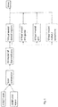
- Figure 1 shows a flow diagram showing consecutive steps of an exemplary embodiment of a method according to the invention.
- CT-scans typically show harder tissues, such as bone material and roots of adjacent teeth.
- an MRI scan could be used to map the softer tissues, such as nerves.
- an intraoral scan can be made to map the contours of the teeth and the soft tissues in the mouth, e.g., to optimize the fit of the drill guide on the soft tissues.
- the CT scans and intraoral scans and/or other types of scans can be combined to form a single virtual model using software which is commonly known in the field.
- a suitable example of such software is the Simplant ® software of Dentsply Implants, Sweden.
- Using different scan technologies may help to improve the accuracy of the virtual 3D model of the scanned area.
- (CB)CT scans may show some bias or distortion which can be compensated by a scan from a different source and type, so the overall accuracy of the virtual 3D model of the scanned area can be improved substantially.
- Ultra sound scanning can for example be used for modeling of the outline of hard bone tissue covered by gum.
- Suitable examples of software that can be used for this purpose include Digital Smile Design ® , Dental Wings ® and 3 Shape Exocad ® .
- the scans are converted into a virtual 3D model of the scanned area, typically in .skp, .dae, .3ds or some other suitable format.
- the optimum dimensions of the dental implant can be calculated. This results in a virtual model of the designed implant.
- the implant should have as much contact surface interfacing with adjacent bone material as the available space allows.
- the implant is individually designed to make optimal use of the available bone space, so it is typically cylindrical, conical or having a shape combining cylindrical and conical sections depending on the bone dimensions.
- the dental implant may also have an asymmetrical shape. In that case the toolings will also comprise one or more individualized osteotomes adapted to the individual asymmetric implant design.
- the virtual model will be used with a 3D printer or similar rapid prototyping process. Therefore, the model will typically be in a .STL or a .OBJ format, to allow the printing software to read it.
- Computer programs for generating a virtual customized dental implant as a 3D print file on basis of CT scans are known in the art.
- a virtual model is generated for a drilling guide on basis of the scan data and on basis of the virtual implant model.
- the drilling guide will have a lower surface resting on adjacent teeth, edentulous area covered by soft tissue, bone or an adjacent temporary implant. To avoid any movement of the guide during drilling, the supporting surface must accurately match the surfaces on which it rests.
- the drilling guide will comprise a drilling hole for guiding the drills to be used.
- This virtual model of the drilling guide will also be in a .STL or a .OBJ format or any other format suitable for processing with 3D printing software.
- a further virtual model is generated of the toolings to be used, in particular the drills.
- a series of drills of increasing diameter will be used.
- the final drill will have a diameter which is typically about 0,4 - 0,6 mm less than the diameter of the dental implant matching the diameter of the dental implant, allowing the implant to be positioned in the drilled hole, e.g., by a self-tapping screw thread, and to make intimate contact with adjacent bone.
- the osteotomy is shaped using osteotomes and the implant is tapped in place using a mallet.
- the dental implant, the drilling guide, and the drills and/or osteotomes are printed by communicating the respective virtual models to the printer.
- the same printer can be used for all components using the same printing material. If so desired, different printers and/or printing materials can be used.
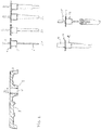
- Figure 2 shows a set of printed drills 1A, 1B, 1C, a drilling guide 2, a mallet 1D and an implant insertion device or driver 1E.
- the set comprises three drills 1A, 1B, 1C of increasing diameter.
- Each of the three drills 1A, 1B, 1C comprise a top end 3, configured to engage a drill head of a drilling machine (not shown).
- Below the top end 3 the drills 1A, 1B, 1C comprise a stop 4 and a cylindrical guiding section 5.
- the guiding sections 5 of all drills 1A, 1B, 1C have the same diameter D and the same length L.
- the drills 1A, 1B, 1C have the actual drill bodies 6 of increasing drilling diameter and of the specifically designed length.
- the drilling guide 2 comprises a strip body 7 with a lower surface 8 having a surface structure exactly matching the geometry of adjacent dentures, so as to immobilize the drill guide 2 during drilling.
- the drill guide 2 comprises a cylindrical bus 9 resting on the jaw between the adjacent teeth.
- the cylindrical bus 9 is provided with a cylindrical guiding opening 10 with the same diameter D as the guiding sections 4.
- the guiding opening 10 is configured to receive the guiding sections 4 of the drill 1A, 1B, 1C in a sliding manner. This ensures that all three drills 1A, 1B, 1C can be positioned accurately and aligned in the very same direction in order to drill along essentially the same drilling axis.
- the axis of the guiding opening 10 may be vertical or may be inclined, depending on how the dental implant (not shown) should be positioned in the treated jaw bone.
- the stop 4 at the top side of the guiding section 5, is wider than the diameter D. These stops 4 ensure that the dentist will not drill deeper than the required depth.
- the guiding opening 10 of the drilling guide can be provided with a stop.
- the resulting osteotomy is slightly smaller than implant in order to provide a narrow fit stabilizing the implant just after its positioning.
- the implant can now be put in place, typically by means of an implant driver 1E.
- an implant driver 1E can be used to engage the individually designed and printed implant 11, e.g., with a conical click connection (not shown).
- the implant driver 1E can be provided with the same cylindrical guiding section 12 as the drills 1A, 1B, 1C, e.g., with an identical stop 13.
- the implant driver 1E can be sterilized after use for reuse. Due to the identical cylindrical shape and size of the guiding section 12 the implant 11 can be guided by means of the drilling guide 2. This way the implant exactly follows the osteotomy and it cannot be screwed or tapped any deeper than the prepared osteotomy.
- the mallet 1D can be used to tap the implant 11 into the osteotomy.
- the mallet is provided with an identical cylindrical guiding section 14 and an identical stop 15, so the implant can be tapped in exactly the right direction.
- the method of the invention enables customized on-demand manufacture of the dental implant, the drilling guide and the drills and/or osteotomes to be used. Therefore, it is not necessary to use cylindrical or conical implants.
- Other implant shapes can also be used and the drilling guide can be designed to guide the drills or other osteotomy modelling devices to form drilling holes of a non-cylindrical outline.
Landscapes
- Health & Medical Sciences (AREA)
- Life Sciences & Earth Sciences (AREA)
- Oral & Maxillofacial Surgery (AREA)
- Veterinary Medicine (AREA)
- Animal Behavior & Ethology (AREA)
- General Health & Medical Sciences (AREA)
- Public Health (AREA)
- Dentistry (AREA)
- Epidemiology (AREA)
- Engineering & Computer Science (AREA)
- Medical Informatics (AREA)
- Surgery (AREA)
- Nuclear Medicine, Radiotherapy & Molecular Imaging (AREA)
- Biomedical Technology (AREA)
- Heart & Thoracic Surgery (AREA)
- Molecular Biology (AREA)
- Physics & Mathematics (AREA)
- High Energy & Nuclear Physics (AREA)
- Pathology (AREA)
- Biophysics (AREA)
- Radiology & Medical Imaging (AREA)
- Chemical & Material Sciences (AREA)
- Materials Engineering (AREA)
- Manufacturing & Machinery (AREA)
- Orthopedic Medicine & Surgery (AREA)
- Optics & Photonics (AREA)
- Theoretical Computer Science (AREA)
- Pulmonology (AREA)
- Robotics (AREA)
- Dental Prosthetics (AREA)
- Prostheses (AREA)
- Dental Tools And Instruments Or Auxiliary Dental Instruments (AREA)
Description
- The present invention relates to a method of customizing and manufacturing a dental implant and associated tooling for implanting the dental implant. The invention also relates to the tooling and to a set of the tooling and an implant customized and manufactured by the method.
- A dental implant is an endosseous surgical implant that serves to replace the root of a lost tooth and that interfaces with a bone of a patient's jaw to support a dental prosthesis such as a crown, bridge, denture, facial prosthesis or to act as an orthodontic anchor. Examples of dental prostheses are disclosed in
US 2013/0230827 . A dental implant, usually a cylindrical or slightly conical component, is typically inserted or screwed into a drilled hole or osteotomy in the jawbone. Dental implants are made of a bio-compatible material, such as titanium or zirconia, and bond to adjacent bone material by osseointegration. An example of a dental implant is disclosed inUS 2014/0272790 . - Before placing the dental implants their position should be carefully planned taking into account the shape, size, and position of the jaw bones and adjacent and opposing teeth. A dentist may use a CT scan of the jawbone and plan the surgery using computer software. The use of CT scanning in complex cases also enables identifying and avoiding vital structures such as the inferior alveolar nerve in the lower jaw and the maxillary sinus in the upper jaw.
- A sufficient body of jaw bone should be maintained between the implant and adjacent denture to ensure a proper blood supply. To this end, a minimum distance of 1.5 to 2 millimeters is usually maintained between the implant and the adjacent teeth on either side of the implant and 1.5 to 3 millimeters between adjacent multiple implants. This means that the available bone site for placement of a dental implant is limited and requires the surgeon to exercise considerable care.
- Generally, the implant is placed a number of months after removal of the lost tooth, in order to allow recovery of the hole left by the root of the lost tooth, the so-called dental alveolus. Alternatively, the implant can be placed before complete healing, when the dental alveolus is still present.
- To place a dental implant an incision is often made first to expose the jaw's bone. The surgeon can then use a tailor made drill guide or stent for optimal positioning and guiding of the drills to be used.
WO 2006/031096 discloses that such a drill guide can be made by stereolithography or rapid prototyping om basis of a CT scan. Pilot holes are placed with precision drills at highly regulated speed to prevent burning or pressure necrosis of the bone. The pilot hole is then expanded by consecutive use of drills with increasingly larger diameters. Usually, between about three to seven drilling steps are carried out. The drills to be used are available in a limited number of standardized diameters, lengths and conical angles. - When the desired hole is drilled, the implant screw is placed. The implant may for instance be a self-tapping screw.
- It is an object of the invention to enable optimum use of the present bone material and the available space for positioning an implant.
- The object of the invention is achieved with a method of customizing and manufacturing a dental implant and tooling for preparing an osteotomy for receiving the dental implant, the method comprising the steps of:
- receiving scan data modeling a jaw bone area comprising a planned position of the osteotomy;
- generating on basis of the scan data a virtual implant model of the dental implant;
- generating a virtual tooling model of the tooling on basis of the virtual implant model;
- computer aided manufacturing of the tooling on basis of the virtual tooling model.
- Customizing the tooling, and preferably also the implant design, makes it possible to make maximum use of the space and bone material available for osseointegration of the implant. Moreover, the on-demand availability of toolings of any desired type and size contributes substantially to procedural efficiency.
- In particular the drills can be customized this way. Instead of being dependent on a limited number of standardized drills, the drill diameter, drill length and optionally a conical angle can be customized and optimized for the specific situation and the individual implant design. Other dental osteotomy modeling devices can also be customized this way, such as scrapers, cutters, chisels, etc..
- Where in prior art systems scan data and 3D printing are typically used for implants or prostheses, requiring an accurate match and fit, the present invention makes it possible to translate scan data to tailor-made and on-demand manufacturable drills and/or other osteotomes.
- Also the dental implant can be made by a computer aided manufacturing process on the basis of said virtual implant model.
- In exceptional cases, the dental implant can be an existing tooth, e.g., a tooth that is transplanted from one part of a patients' jaw to another part. In such a case, the scan data include scan data of the tooth to be transplanted. These scan data are the basis of the virtual implant model.
- The scan data model at least the section of the jaw bone comprising the alveolus and adjacent dentures.
- The scan data can for example be obtained by a computed tomography (CT) scan. Other scanning technologies, include but are not limited to CBCT, MRT, MRI, PET, SPECT, ultra sound, destructive scanning, active triangulation, passive triangulation, confocal scanning, and TOF (Time Of Flight). Combinations of scans can also be used. For instance, CT-scans can be used for modeling the local anatomy of the harder tissues, such as local jaw bone tissue, while an MRI scan can be used for modeling softer tissues, such as nerves. CT-scans may for example also be combined with intraoral scans.
- Scan methods are generating either surface descriptions for example in STL-format or volumetric data for example in a so called "voxel"-format that can be transformed into surface data by generally available software applications.
- The scan data are used to produce a computer generated virtual implant model of the dental implant. The implant can be designed to make optimum use of available space and bone material. A suitable example of a process of generating a virtual implant model is disclosed in
WO 2006/031096 . The model includes geometrical information of the dental implant and positioning data defining the exact position and orientation of the dental implant in the jaw bone. - The design of the generated implant model may have any suitable shape or diameter at any level of the implant, the implant being wider at the top and narrower at the lowest point.
- Additionally, a virtual model of a drill guide can be generated on basis of the virtual implant model. The drill guide is adapted to the shape and size of the implant. A suitable example of a process of generating a virtual drill guide model on basis of CT-scan data is also disclosed in
WO 2006/031096 . - Knowing the dimensions of the designed implant, the required drills can be designed. The drills can be designed for preparing a hole providing a tight fit for the implant in order to provide initial stability of the implant just after positioning.
- Since the drills are manufactured individually they do not need to have a standard diameter. Design parameters that can be derived from the virtual implant model include the diameter, the length and optionally a conical angle or pitch. The virtual tooling model for the drills may be based on a generic virtual tooling model to be completed by open design parameters, in particular diameter and length.
- After generation of the virtual models of the implant, the toolings and optionally the drill guide, the respective products can be manufactured by a computer aided process, e.g., a rapid prototyping process allowing on-demand precise manufacture of the desired products. Suitable rapid prototyping process include stereolithography, fused deposition modeling, laminated object modeling, selective laser sintering, computer aided milling and, in particular, 3D printing. Combinations can also be used. For instance, a slightly oversized product may be printed and subsequently milled to improve dimensional accuracy or to obtain a desired surface finishing.
- Notwithstanding the geometrical diversity of the products, the same rapid typing process, device and/or materials can be used to manufacture the implant, the toolings and, optionally, the drilling guide. With a single 3D printer the surgeon may print all the elements he needs with the preparation for a treatment. Furthermore, use of a 3D printer allows the surgeon to use different materials for specific layer. For instance, the implant may be provided with a top surface with a material stimulating growth of bone material. For instance, apatite coated zirconia was found to promote adherence to jaw bone material. The drill surfaces may for example be provided with hemostyptics or materials promoting healing of the drilled tissues.
- Examples of printing materials include, but are not limited to, ceramics based on zirconia, apatite, ytrria, hafnia, alumina, ceria, magnesia, titania, silicon nitride, silicon carbide, silica-alumina-nitride, mullite, garnets, porcelain, or mixtures thereof. In particular zirconia based materials show good biocompatible properties.
- An example of a suitable 3D printer is the
Objet Eden260VTM 3D Printer, commercially available from Stratasys Ltd. - After use the toolings can be disposed. Optionally, the printing material can be recycled.
- A set of the aforementioned toolings can be used for preparing implantation of a dental implant. Such a set of toolings may for example include a drill comprising a guiding section and a drilling guide comprising a guiding opening configured to receive the guiding section of the drill in a sliding manner. This allows accurate positioning and directing of the drill. The guiding section may for instance be a collar, e.g., a cylindrical collar, the drill guide having an opening of a matching diameter.
- The set may for instance comprise a series of drills of increasing diameter, all provided with a guiding section of the same dimensions. As a result all drills of the series can be accurately guided by the drill guide.
- Optionally, the guiding section of the drill or the matching guiding opening in the drill guide may comprise a stop to prevent that the drill may be moved to deep. The exact position of the stop can be part of the virtual tooling model derived from the scan data.
- The set may also comprise a customized dental implant, e.g., printed with the same 3D printer or other rapid prototyping station as the toolings, optionally of the same printing material.
- The invention will be further explained with reference to the accompanying drawings, showing exemplary embodiments.
-
-
Figure 1 : shows a flow diagram representing the method according to the invention; -
Figure 2 shows a set of toolings according to the invention. -
Figure 1 shows a flow diagram showing consecutive steps of an exemplary embodiment of a method according to the invention. - After removal of a patients tooth the remaining dental alveolus is usually allowed to heal for some months to grow fresh jaw bone material. When the dental alveolus is sufficiently healed a CT scan is made. CT-scans typically show harder tissues, such as bone material and roots of adjacent teeth. Additionally, or alternatively, an MRI scan could be used to map the softer tissues, such as nerves. Optionally, an intraoral scan can be made to map the contours of the teeth and the soft tissues in the mouth, e.g., to optimize the fit of the drill guide on the soft tissues.
- The CT scans and intraoral scans and/or other types of scans can be combined to form a single virtual model using software which is commonly known in the field. A suitable example of such software is the Simplant® software of Dentsply Implants, Sweden. Using different scan technologies may help to improve the accuracy of the virtual 3D model of the scanned area. For instance, (CB)CT scans may show some bias or distortion which can be compensated by a scan from a different source and type, so the overall accuracy of the virtual 3D model of the scanned area can be improved substantially. Ultra sound scanning can for example be used for modeling of the outline of hard bone tissue covered by gum. This can be combined with other scans, e.g., with MRI scans and/or intraoral scans which are typically more accurate with softer tissues. Suitable examples of software that can be used for this purpose include Digital Smile Design®, Dental Wings® and 3 Shape Exocad®.
- The scans are converted into a virtual 3D model of the scanned area, typically in .skp, .dae, .3ds or some other suitable format. On basis of this virtual 3D model the optimum dimensions of the dental implant can be calculated. This results in a virtual model of the designed implant. The implant should have as much contact surface interfacing with adjacent bone material as the available space allows. The implant is individually designed to make optimal use of the available bone space, so it is typically cylindrical, conical or having a shape combining cylindrical and conical sections depending on the bone dimensions. The dental implant may also have an asymmetrical shape. In that case the toolings will also comprise one or more individualized osteotomes adapted to the individual asymmetric implant design.
- The virtual model will be used with a 3D printer or similar rapid prototyping process. Therefore, the model will typically be in a .STL or a .OBJ format, to allow the printing software to read it. Computer programs for generating a virtual customized dental implant as a 3D print file on basis of CT scans are known in the art.
- In a next step a virtual model is generated for a drilling guide on basis of the scan data and on basis of the virtual implant model. The drilling guide will have a lower surface resting on adjacent teeth, edentulous area covered by soft tissue, bone or an adjacent temporary implant. To avoid any movement of the guide during drilling, the supporting surface must accurately match the surfaces on which it rests. The drilling guide will comprise a drilling hole for guiding the drills to be used. This virtual model of the drilling guide will also be in a .STL or a .OBJ format or any other format suitable for processing with 3D printing software.
- A further virtual model is generated of the toolings to be used, in particular the drills. Usually, a series of drills of increasing diameter will be used. The final drill will have a diameter which is typically about 0,4 - 0,6 mm less than the diameter of the dental implant matching the diameter of the dental implant, allowing the implant to be positioned in the drilled hole, e.g., by a self-tapping screw thread, and to make intimate contact with adjacent bone. Alternatively the osteotomy is shaped using osteotomes and the implant is tapped in place using a mallet.
- In a next step, the dental implant, the drilling guide, and the drills and/or osteotomes are printed by communicating the respective virtual models to the printer. The same printer can be used for all components using the same printing material. If so desired, different printers and/or printing materials can be used.
-
Figure 2 shows a set of printed drills 1A, 1B, 1C, adrilling guide 2, a mallet 1D and an implant insertion device or driver 1E. - The set comprises three drills 1A, 1B, 1C of increasing diameter. Each of the three drills 1A, 1B, 1C comprise a top end 3, configured to engage a drill head of a drilling machine (not shown). Below the top end 3 the drills 1A, 1B, 1C comprise a stop 4 and a cylindrical guiding section 5. The guiding sections 5 of all drills 1A, 1B, 1C have the same diameter D and the same length L. Below the guiding sections 5 the drills 1A, 1B, 1C have the actual drill bodies 6 of increasing drilling diameter and of the specifically designed length.
- The
drilling guide 2 comprises astrip body 7 with alower surface 8 having a surface structure exactly matching the geometry of adjacent dentures, so as to immobilize thedrill guide 2 during drilling. At the position of the alveolus that is to be treated, thedrill guide 2 comprises a cylindrical bus 9 resting on the jaw between the adjacent teeth. The cylindrical bus 9 is provided with a cylindrical guiding opening 10 with the same diameter D as the guiding sections 4. The guiding opening 10 is configured to receive the guiding sections 4 of the drill 1A, 1B, 1C in a sliding manner. This ensures that all three drills 1A, 1B, 1C can be positioned accurately and aligned in the very same direction in order to drill along essentially the same drilling axis. The axis of the guiding opening 10 may be vertical or may be inclined, depending on how the dental implant (not shown) should be positioned in the treated jaw bone. - The stop 4 at the top side of the guiding section 5, is wider than the diameter D. These stops 4 ensure that the dentist will not drill deeper than the required depth. In an alternative embodiment the guiding opening 10 of the drilling guide can be provided with a stop.
- The resulting osteotomy is slightly smaller than implant in order to provide a narrow fit stabilizing the implant just after its positioning.
- The implant can now be put in place, typically by means of an implant driver 1E. Such an implant driver 1E can be used to engage the individually designed and printed implant 11, e.g., with a conical click connection (not shown). The implant driver 1E can be provided with the same
cylindrical guiding section 12 as the drills 1A, 1B, 1C, e.g., with anidentical stop 13. The implant driver 1E can be sterilized after use for reuse. Due to the identical cylindrical shape and size of the guidingsection 12 the implant 11 can be guided by means of thedrilling guide 2. This way the implant exactly follows the osteotomy and it cannot be screwed or tapped any deeper than the prepared osteotomy. - Alternatively, the mallet 1D can be used to tap the implant 11 into the osteotomy. Like the implant driver 1E, the mallet is provided with an identical
cylindrical guiding section 14 and an identical stop 15, so the implant can be tapped in exactly the right direction. - The method of the invention enables customized on-demand manufacture of the dental implant, the drilling guide and the drills and/or osteotomes to be used. Therefore, it is not necessary to use cylindrical or conical implants. Other implant shapes can also be used and the drilling guide can be designed to guide the drills or other osteotomy modelling devices to form drilling holes of a non-cylindrical outline.
Claims (9)
- Method of customizing and manufacturing tooling for preparing an osteotomy for receiving a dental implant, the method comprising the steps of:- receiving scan data modeling a planned position of the osteotomy and surrounding jaw bone area;- generating on the basis of the scan data a virtual implant model of the dental implant;- generating a virtual tooling model of the tooling on basis of the virtual implant model;- computer aided manufacturing of the tooling on the basis of the virtual tooling model.
- Method according to claim 1, wherein the dental implant is made by a computer aided manufacturing process on the basis of said virtual implant model.
- Method according to claim 1 or 2, wherein the tooling is manufactured by a rapid prototyping process.
- Method according to claim 3, wherein the rapid prototyping process includes 3D printing, stereolithography , fused deposition modeling, laminated object modeling, selective laser sintering, or computer aided milling.
- Method according to claim 4, wherein the toolings are formed, e.g., printed, of the same or different material as the dental implants, e.g., a printable composition on basis of titanium and/or zirconium.
- Method according to any one of the preceding claims, wherein the toolings include one or more drills and optionally further osteotomy modeling devices, such as scrapers, cutters, and/or chisels.
- Method according to any preceding claim, wherein the scan date are obtained by computed tomography (CT) scanning.
- Method according to claim 7, wherein the CT-scan is combined with additional scans, e.g., an MRI scan and/or intraoral scan.
- A computer program, or set of computer programs, comprising at least one software code portion or a computer program product storing at least one software code portion, the at least one software code portion, being configured for executing the method according to one or more of the claims 1-8 when run on a computer aided manufacturing system.
Applications Claiming Priority (2)
| Application Number | Priority Date | Filing Date | Title |
|---|---|---|---|
| EP15167007.2A EP3090700A1 (en) | 2015-05-08 | 2015-05-08 | Customized dental implant and associated tooling |
| PCT/EP2016/059980 WO2016180700A1 (en) | 2015-05-08 | 2016-05-04 | Customized dental implant and associated tooling |
Publications (2)
| Publication Number | Publication Date |
|---|---|
| EP3300480A1 EP3300480A1 (en) | 2018-04-04 |
| EP3300480B1 true EP3300480B1 (en) | 2021-12-01 |
Family
ID=53051770
Family Applications (2)
| Application Number | Title | Priority Date | Filing Date |
|---|---|---|---|
| EP15167007.2A Withdrawn EP3090700A1 (en) | 2015-05-08 | 2015-05-08 | Customized dental implant and associated tooling |
| EP16721779.3A Active EP3300480B1 (en) | 2015-05-08 | 2016-05-04 | Customized dental implant and associated tooling |
Family Applications Before (1)
| Application Number | Title | Priority Date | Filing Date |
|---|---|---|---|
| EP15167007.2A Withdrawn EP3090700A1 (en) | 2015-05-08 | 2015-05-08 | Customized dental implant and associated tooling |
Country Status (7)
| Country | Link |
|---|---|
| US (1) | US11839525B2 (en) |
| EP (2) | EP3090700A1 (en) |
| JP (1) | JP7050662B2 (en) |
| KR (1) | KR102646499B1 (en) |
| BR (1) | BR112017024010B1 (en) |
| ES (1) | ES2909502T3 (en) |
| WO (1) | WO2016180700A1 (en) |
Families Citing this family (10)
| Publication number | Priority date | Publication date | Assignee | Title |
|---|---|---|---|---|
| US8011927B2 (en) * | 2008-04-16 | 2011-09-06 | Biomet 3I, Llc | Method for pre-operative visualization of instrumentation used with a surgical guide for dental implant placement |
| US11007035B2 (en) | 2017-03-16 | 2021-05-18 | Viax Dental Technologies Llc | System for preparing teeth for the placement of veneers |
| TWI633875B (en) * | 2017-09-15 | 2018-09-01 | 霽邦有限公司 | Method and system for manufacturing apical resection surgery guide plate and computer-readable recording medium |
| KR101889010B1 (en) | 2017-09-20 | 2018-08-16 | 주식회사 디맥스 | Manufacturing method of dental surgical guide |
| KR102043971B1 (en) * | 2018-03-08 | 2019-11-12 | 주식회사 쓰리디산업영상 | Method for extracting dental membrane shape, method for recommending membrane products, and apparatus implementing the methods |
| CN111000583A (en) * | 2019-12-31 | 2020-04-14 | 北京大学口腔医学院 | A parallel projection positioning bracket for dental implants |
| CN113499093A (en) * | 2021-07-12 | 2021-10-15 | 北京大学口腔医学院 | X-ray film holder for implant evaluation and manufacturing method |
| WO2023148410A1 (en) * | 2022-02-01 | 2023-08-10 | Tech Xika Ptt, S.L. | Method for manufacturing a splint or surgical guide for the implantation of at least one dental implant |
| CN114948280B (en) * | 2022-05-13 | 2023-02-03 | 四川大学 | A variable positioning device and positioning method for a dental drill |
| US20250049546A1 (en) * | 2023-08-09 | 2025-02-13 | Rtrs Investment, Llc | Implants, functionalized implant surfaces and related systems, devices, computer program products, and methods |
Citations (1)
| Publication number | Priority date | Publication date | Assignee | Title |
|---|---|---|---|---|
| US20140272790A1 (en) * | 2013-03-14 | 2014-09-18 | William M. Aerni | Universal digital dental implant scanning code and method |
Family Cites Families (29)
| Publication number | Priority date | Publication date | Assignee | Title |
|---|---|---|---|---|
| US5967777A (en) * | 1997-11-24 | 1999-10-19 | Klein; Michael | Surgical template assembly and method for drilling and installing dental implants |
| US6039568A (en) * | 1998-06-02 | 2000-03-21 | Hinds; Kenneth F. | Tooth shaped dental implants |
| WO2004075771A1 (en) * | 2003-02-28 | 2004-09-10 | Materialise, Naamloze Vennootschap | Method for placing and manufacturing a dental superstructure, method for placing implants and accessories used thereby |
| EP1791491A1 (en) | 2004-09-14 | 2007-06-06 | Oratio B.V. | Method of manufacturing and installing a ceramic dental implant with an aesthetic implant abutment |
| BE1016374A3 (en) * | 2005-02-03 | 2006-09-05 | Moyer Philippe Albert Paul Ghi | Implantable dental prosthesis producing method for patient`s jaw, involves placing real guiding cylinders in drilled holes so as to form surgical guide, and drilling jaw model through surgical guide using guiding cylinders |
| US7806691B2 (en) * | 2005-03-30 | 2010-10-05 | Bio Dental Solution Ltd | Method and system for fixing removable dentures |
| US7835811B2 (en) * | 2006-10-07 | 2010-11-16 | Voxelogix Corporation | Surgical guides and methods for positioning artificial teeth and dental implants |
| WO2008112925A2 (en) * | 2007-03-13 | 2008-09-18 | Voxelogix Corporation | Direct manufacture of dental and medical devices |
| BRPI0815703A2 (en) * | 2007-08-24 | 2015-02-10 | 2Ingis S A | MANUFACTURING PROCESS OF A DENTAL PROSTHESIS AND A DENTAL SURGICAL GUIDE. |
| US9522046B2 (en) * | 2010-08-23 | 2016-12-20 | Gip | Robotic surgery system |
| US9060832B2 (en) * | 2007-11-28 | 2015-06-23 | 3M Innovative Properties Company | Fabrication of dental articles using digitally-controlled reductive and digitally-controlled additive processes |
| JP2011507615A (en) * | 2007-12-21 | 2011-03-10 | スリーエム イノベイティブ プロパティズ カンパニー | Method of creating virtual dentition model and manufacturing method of orthodontic retainer using it |
| JP2011509812A (en) * | 2008-01-23 | 2011-03-31 | センサブル テクノロジーズ インコーポレイテッド | Tactile controllable dental modeling system |
| US8011927B2 (en) * | 2008-04-16 | 2011-09-06 | Biomet 3I, Llc | Method for pre-operative visualization of instrumentation used with a surgical guide for dental implant placement |
| JP5322621B2 (en) * | 2008-12-19 | 2013-10-23 | 京セラメディカル株式会社 | Production apparatus for oral model for stent production and production system for oral model for stent production |
| US8827704B2 (en) * | 2009-02-04 | 2014-09-09 | Mid Corp | System, method and apparatus for implementing dental implants |
| TWI535424B (en) * | 2009-03-13 | 2016-06-01 | 神農資訊股份有限公司 | System and method for manufacturing a dental implant surgical guide |
| EP2353540A1 (en) * | 2010-01-28 | 2011-08-10 | Sudimplant | Assembly of a dental implant and a prosthetic element |
| JPWO2012004937A1 (en) * | 2010-07-07 | 2013-09-02 | 有限会社シエスタ | Implant design method, implant design apparatus, and implant design program |
| KR20120053455A (en) * | 2010-11-17 | 2012-05-25 | 안경숙 | Tooth grinding guide device for prosthodontics |
| US20140038134A1 (en) * | 2012-01-27 | 2014-02-06 | Hao Nguyen | Custom dental implants, systems, devices and methods |
| WO2013138583A1 (en) * | 2012-03-16 | 2013-09-19 | James Glidewell Dental Ceramics, Inc. | Patient-specific system for restoring missing dentition |
| US9636229B2 (en) * | 2012-09-20 | 2017-05-02 | Conformis, Inc. | Solid freeform fabrication of implant components |
| US20140212843A1 (en) * | 2013-01-30 | 2014-07-31 | Frank Chiu | Custom Dental Implant Fixture |
| WO2015030652A1 (en) * | 2013-08-26 | 2015-03-05 | Elos Medtech Timmersdala Ab | Dental drill system |
| JP6617103B2 (en) * | 2013-11-20 | 2019-12-04 | デンツプライ シロナ インコーポレーテッド | Endodontic device formed of or coated with a porous material |
| US10016256B2 (en) * | 2014-03-07 | 2018-07-10 | Earl Wayne Simmons, Jr. | Methods and apparatus for preparing a dental implant site |
| US9211165B2 (en) * | 2014-03-19 | 2015-12-15 | GRS Guide System, Inc. | Positioning and installing surgical drilling devices and related devices and systems |
| US9283055B2 (en) * | 2014-04-01 | 2016-03-15 | FPJ Enterprises, LLC | Method for establishing drill trajectory for dental implants |
-
2015
- 2015-05-08 EP EP15167007.2A patent/EP3090700A1/en not_active Withdrawn
-
2016
- 2016-05-04 ES ES16721779T patent/ES2909502T3/en active Active
- 2016-05-04 EP EP16721779.3A patent/EP3300480B1/en active Active
- 2016-05-04 KR KR1020177035416A patent/KR102646499B1/en active Active
- 2016-05-04 BR BR112017024010-6A patent/BR112017024010B1/en active IP Right Grant
- 2016-05-04 JP JP2018509982A patent/JP7050662B2/en active Active
- 2016-05-04 US US15/572,617 patent/US11839525B2/en active Active
- 2016-05-04 WO PCT/EP2016/059980 patent/WO2016180700A1/en not_active Ceased
Patent Citations (1)
| Publication number | Priority date | Publication date | Assignee | Title |
|---|---|---|---|---|
| US20140272790A1 (en) * | 2013-03-14 | 2014-09-18 | William M. Aerni | Universal digital dental implant scanning code and method |
Also Published As
| Publication number | Publication date |
|---|---|
| BR112017024010A2 (en) | 2018-07-17 |
| US11839525B2 (en) | 2023-12-12 |
| KR20180018537A (en) | 2018-02-21 |
| KR102646499B1 (en) | 2024-03-11 |
| ES2909502T3 (en) | 2022-05-06 |
| JP7050662B2 (en) | 2022-04-08 |
| US20180140392A1 (en) | 2018-05-24 |
| WO2016180700A1 (en) | 2016-11-17 |
| JP2018514362A (en) | 2018-06-07 |
| BR112017024010B1 (en) | 2020-12-15 |
| EP3300480A1 (en) | 2018-04-04 |
| EP3090700A1 (en) | 2016-11-09 |
Similar Documents
| Publication | Publication Date | Title |
|---|---|---|
| US11839525B2 (en) | Customized dental implant and associated tooling | |
| US11540900B2 (en) | Dental ridge augmentation matrix with integrated dental implant surgical drill guide system | |
| JP6063516B2 (en) | Method for generating accurate bone and soft tissue digital dental models | |
| US9519749B2 (en) | Surgical guide and method | |
| Chrcanovic et al. | Accuracy evaluation of computed tomography–derived stereolithographic surgical guides in zygomatic implant placement in human cadavers | |
| US8425229B2 (en) | Method and system for dental planning | |
| US20150147716A1 (en) | Surgical guide system for dental implantology and method for making the same | |
| Moin et al. | Accuracy of computer-assisted template-guided autotransplantation of teeth with custom three-dimensional designed/printed surgical tooling: a cadaveric study | |
| EP3808309A1 (en) | Method for designing an implant | |
| EP2120781A2 (en) | Stent for implant guide and prosthetics | |
| Grecchi et al. | A novel guided zygomatic implant surgery system compared to free hand: A human cadaver study on accuracy | |
| Sans et al. | Accuracy of CAD-CAM surgically guided tooth autotransplantation using guided templates and custom-designed osteotomes in human cadaver mandibles | |
| Li-Rodríguez et al. | Accuracy of a guided implant system with milled surgical templates | |
| Mao et al. | Application of titanium 3D‐printed double‐sleeve guide for zygomatic implants: A technique report | |
| KR102928267B1 (en) | Osteotome | |
| US20230172693A1 (en) | Multi-axis multi-anchored implants | |
| RU2798031C1 (en) | Navigation template for navigated trepan biopsy of the jaw bones | |
| RU2769621C2 (en) | Guiding template for dental surgery | |
| US20230329788A1 (en) | Osteotomy Based Scan Body for Surgical Vector Capture on a Patient Specific Bone Structure | |
| Petrov et al. | Sequencing osteotomes to overcome challenges presented by deficient bone quality and quality in potential implant sites. | |
| Maffei et al. | Guided surgery with narrow implant: a case report using CAD/CAM technology | |
| Palmaria Lagumbay et al. | Computer-assisted Implant Surgery | |
| Guentsch | Guided Surgery for Placing Immediate Implants using Standard Osteotomy Preparation or Osseodensification | |
| Pradíes | Accuracy of a guided implant system with milled surgical templates | |
| Malara et al. | STRATEGIES FOR COMPUTER-AIDED DESIGNING OF SURGICAL GUIDES FOR DENTAL IMPLANT PROCEDURES BASED ON CONE BEAM COMPUTED TOMOGRAPHY |
Legal Events
| Date | Code | Title | Description |
|---|---|---|---|
| STAA | Information on the status of an ep patent application or granted ep patent |
Free format text: STATUS: THE INTERNATIONAL PUBLICATION HAS BEEN MADE |
|
| PUAI | Public reference made under article 153(3) epc to a published international application that has entered the european phase |
Free format text: ORIGINAL CODE: 0009012 |
|
| STAA | Information on the status of an ep patent application or granted ep patent |
Free format text: STATUS: REQUEST FOR EXAMINATION WAS MADE |
|
| 17P | Request for examination filed |
Effective date: 20171207 |
|
| AK | Designated contracting states |
Kind code of ref document: A1 Designated state(s): AL AT BE BG CH CY CZ DE DK EE ES FI FR GB GR HR HU IE IS IT LI LT LU LV MC MK MT NL NO PL PT RO RS SE SI SK SM TR |
|
| AX | Request for extension of the european patent |
Extension state: BA ME |
|
| DAV | Request for validation of the european patent (deleted) | ||
| DAX | Request for extension of the european patent (deleted) | ||
| STAA | Information on the status of an ep patent application or granted ep patent |
Free format text: STATUS: EXAMINATION IS IN PROGRESS |
|
| 17Q | First examination report despatched |
Effective date: 20200420 |
|
| GRAP | Despatch of communication of intention to grant a patent |
Free format text: ORIGINAL CODE: EPIDOSNIGR1 |
|
| STAA | Information on the status of an ep patent application or granted ep patent |
Free format text: STATUS: GRANT OF PATENT IS INTENDED |
|
| INTG | Intention to grant announced |
Effective date: 20210625 |
|
| GRAS | Grant fee paid |
Free format text: ORIGINAL CODE: EPIDOSNIGR3 |
|
| GRAA | (expected) grant |
Free format text: ORIGINAL CODE: 0009210 |
|
| STAA | Information on the status of an ep patent application or granted ep patent |
Free format text: STATUS: THE PATENT HAS BEEN GRANTED |
|
| AK | Designated contracting states |
Kind code of ref document: B1 Designated state(s): AL AT BE BG CH CY CZ DE DK EE ES FI FR GB GR HR HU IE IS IT LI LT LU LV MC MK MT NL NO PL PT RO RS SE SI SK SM TR |
|
| RAP3 | Party data changed (applicant data changed or rights of an application transferred) |
Owner name: STICHTING VU |
|
| REG | Reference to a national code |
Ref country code: GB Ref legal event code: FG4D |
|
| REG | Reference to a national code |
Ref country code: AT Ref legal event code: REF Ref document number: 1451057 Country of ref document: AT Kind code of ref document: T Effective date: 20211215 Ref country code: CH Ref legal event code: EP |
|
| REG | Reference to a national code |
Ref country code: IE Ref legal event code: FG4D |
|
| REG | Reference to a national code |
Ref country code: DE Ref legal event code: R096 Ref document number: 602016066787 Country of ref document: DE |
|
| REG | Reference to a national code |
Ref country code: NL Ref legal event code: FP |
|
| REG | Reference to a national code |
Ref country code: SE Ref legal event code: TRGR |
|
| REG | Reference to a national code |
Ref country code: LT Ref legal event code: MG9D |
|
| REG | Reference to a national code |
Ref country code: AT Ref legal event code: MK05 Ref document number: 1451057 Country of ref document: AT Kind code of ref document: T Effective date: 20211201 |
|
| PG25 | Lapsed in a contracting state [announced via postgrant information from national office to epo] |
Ref country code: RS Free format text: LAPSE BECAUSE OF FAILURE TO SUBMIT A TRANSLATION OF THE DESCRIPTION OR TO PAY THE FEE WITHIN THE PRESCRIBED TIME-LIMIT Effective date: 20211201 Ref country code: LT Free format text: LAPSE BECAUSE OF FAILURE TO SUBMIT A TRANSLATION OF THE DESCRIPTION OR TO PAY THE FEE WITHIN THE PRESCRIBED TIME-LIMIT Effective date: 20211201 Ref country code: FI Free format text: LAPSE BECAUSE OF FAILURE TO SUBMIT A TRANSLATION OF THE DESCRIPTION OR TO PAY THE FEE WITHIN THE PRESCRIBED TIME-LIMIT Effective date: 20211201 Ref country code: BG Free format text: LAPSE BECAUSE OF FAILURE TO SUBMIT A TRANSLATION OF THE DESCRIPTION OR TO PAY THE FEE WITHIN THE PRESCRIBED TIME-LIMIT Effective date: 20220301 Ref country code: AT Free format text: LAPSE BECAUSE OF FAILURE TO SUBMIT A TRANSLATION OF THE DESCRIPTION OR TO PAY THE FEE WITHIN THE PRESCRIBED TIME-LIMIT Effective date: 20211201 |
|
| REG | Reference to a national code |
Ref country code: ES Ref legal event code: FG2A Ref document number: 2909502 Country of ref document: ES Kind code of ref document: T3 Effective date: 20220506 |
|
| PG25 | Lapsed in a contracting state [announced via postgrant information from national office to epo] |
Ref country code: PL Free format text: LAPSE BECAUSE OF FAILURE TO SUBMIT A TRANSLATION OF THE DESCRIPTION OR TO PAY THE FEE WITHIN THE PRESCRIBED TIME-LIMIT Effective date: 20211201 Ref country code: NO Free format text: LAPSE BECAUSE OF FAILURE TO SUBMIT A TRANSLATION OF THE DESCRIPTION OR TO PAY THE FEE WITHIN THE PRESCRIBED TIME-LIMIT Effective date: 20220301 Ref country code: LV Free format text: LAPSE BECAUSE OF FAILURE TO SUBMIT A TRANSLATION OF THE DESCRIPTION OR TO PAY THE FEE WITHIN THE PRESCRIBED TIME-LIMIT Effective date: 20211201 Ref country code: HR Free format text: LAPSE BECAUSE OF FAILURE TO SUBMIT A TRANSLATION OF THE DESCRIPTION OR TO PAY THE FEE WITHIN THE PRESCRIBED TIME-LIMIT Effective date: 20211201 Ref country code: GR Free format text: LAPSE BECAUSE OF FAILURE TO SUBMIT A TRANSLATION OF THE DESCRIPTION OR TO PAY THE FEE WITHIN THE PRESCRIBED TIME-LIMIT Effective date: 20220302 |
|
| PG25 | Lapsed in a contracting state [announced via postgrant information from national office to epo] |
Ref country code: SM Free format text: LAPSE BECAUSE OF FAILURE TO SUBMIT A TRANSLATION OF THE DESCRIPTION OR TO PAY THE FEE WITHIN THE PRESCRIBED TIME-LIMIT Effective date: 20211201 Ref country code: SK Free format text: LAPSE BECAUSE OF FAILURE TO SUBMIT A TRANSLATION OF THE DESCRIPTION OR TO PAY THE FEE WITHIN THE PRESCRIBED TIME-LIMIT Effective date: 20211201 Ref country code: RO Free format text: LAPSE BECAUSE OF FAILURE TO SUBMIT A TRANSLATION OF THE DESCRIPTION OR TO PAY THE FEE WITHIN THE PRESCRIBED TIME-LIMIT Effective date: 20211201 Ref country code: PT Free format text: LAPSE BECAUSE OF FAILURE TO SUBMIT A TRANSLATION OF THE DESCRIPTION OR TO PAY THE FEE WITHIN THE PRESCRIBED TIME-LIMIT Effective date: 20220401 Ref country code: EE Free format text: LAPSE BECAUSE OF FAILURE TO SUBMIT A TRANSLATION OF THE DESCRIPTION OR TO PAY THE FEE WITHIN THE PRESCRIBED TIME-LIMIT Effective date: 20211201 Ref country code: CZ Free format text: LAPSE BECAUSE OF FAILURE TO SUBMIT A TRANSLATION OF THE DESCRIPTION OR TO PAY THE FEE WITHIN THE PRESCRIBED TIME-LIMIT Effective date: 20211201 |
|
| REG | Reference to a national code |
Ref country code: DE Ref legal event code: R097 Ref document number: 602016066787 Country of ref document: DE |
|
| PG25 | Lapsed in a contracting state [announced via postgrant information from national office to epo] |
Ref country code: IS Free format text: LAPSE BECAUSE OF FAILURE TO SUBMIT A TRANSLATION OF THE DESCRIPTION OR TO PAY THE FEE WITHIN THE PRESCRIBED TIME-LIMIT Effective date: 20220401 |
|
| PLBE | No opposition filed within time limit |
Free format text: ORIGINAL CODE: 0009261 |
|
| STAA | Information on the status of an ep patent application or granted ep patent |
Free format text: STATUS: NO OPPOSITION FILED WITHIN TIME LIMIT |
|
| PG25 | Lapsed in a contracting state [announced via postgrant information from national office to epo] |
Ref country code: DK Free format text: LAPSE BECAUSE OF FAILURE TO SUBMIT A TRANSLATION OF THE DESCRIPTION OR TO PAY THE FEE WITHIN THE PRESCRIBED TIME-LIMIT Effective date: 20211201 Ref country code: AL Free format text: LAPSE BECAUSE OF FAILURE TO SUBMIT A TRANSLATION OF THE DESCRIPTION OR TO PAY THE FEE WITHIN THE PRESCRIBED TIME-LIMIT Effective date: 20211201 |
|
| 26N | No opposition filed |
Effective date: 20220902 |
|
| PG25 | Lapsed in a contracting state [announced via postgrant information from national office to epo] |
Ref country code: SI Free format text: LAPSE BECAUSE OF FAILURE TO SUBMIT A TRANSLATION OF THE DESCRIPTION OR TO PAY THE FEE WITHIN THE PRESCRIBED TIME-LIMIT Effective date: 20211201 |
|
| PG25 | Lapsed in a contracting state [announced via postgrant information from national office to epo] |
Ref country code: MC Free format text: LAPSE BECAUSE OF FAILURE TO SUBMIT A TRANSLATION OF THE DESCRIPTION OR TO PAY THE FEE WITHIN THE PRESCRIBED TIME-LIMIT Effective date: 20211201 Ref country code: LU Free format text: LAPSE BECAUSE OF NON-PAYMENT OF DUE FEES Effective date: 20220504 |
|
| PG25 | Lapsed in a contracting state [announced via postgrant information from national office to epo] |
Ref country code: IE Free format text: LAPSE BECAUSE OF NON-PAYMENT OF DUE FEES Effective date: 20220504 |
|
| P01 | Opt-out of the competence of the unified patent court (upc) registered |
Effective date: 20230714 |
|
| PG25 | Lapsed in a contracting state [announced via postgrant information from national office to epo] |
Ref country code: HU Free format text: LAPSE BECAUSE OF FAILURE TO SUBMIT A TRANSLATION OF THE DESCRIPTION OR TO PAY THE FEE WITHIN THE PRESCRIBED TIME-LIMIT; INVALID AB INITIO Effective date: 20160504 |
|
| PG25 | Lapsed in a contracting state [announced via postgrant information from national office to epo] |
Ref country code: MK Free format text: LAPSE BECAUSE OF FAILURE TO SUBMIT A TRANSLATION OF THE DESCRIPTION OR TO PAY THE FEE WITHIN THE PRESCRIBED TIME-LIMIT Effective date: 20211201 Ref country code: CY Free format text: LAPSE BECAUSE OF FAILURE TO SUBMIT A TRANSLATION OF THE DESCRIPTION OR TO PAY THE FEE WITHIN THE PRESCRIBED TIME-LIMIT Effective date: 20211201 |
|
| PG25 | Lapsed in a contracting state [announced via postgrant information from national office to epo] |
Ref country code: TR Free format text: LAPSE BECAUSE OF FAILURE TO SUBMIT A TRANSLATION OF THE DESCRIPTION OR TO PAY THE FEE WITHIN THE PRESCRIBED TIME-LIMIT Effective date: 20211201 |
|
| PG25 | Lapsed in a contracting state [announced via postgrant information from national office to epo] |
Ref country code: MT Free format text: LAPSE BECAUSE OF FAILURE TO SUBMIT A TRANSLATION OF THE DESCRIPTION OR TO PAY THE FEE WITHIN THE PRESCRIBED TIME-LIMIT Effective date: 20211201 |
|
| PGFP | Annual fee paid to national office [announced via postgrant information from national office to epo] |
Ref country code: NL Payment date: 20250526 Year of fee payment: 10 |
|
| PGFP | Annual fee paid to national office [announced via postgrant information from national office to epo] |
Ref country code: DE Payment date: 20250529 Year of fee payment: 10 |
|
| PGFP | Annual fee paid to national office [announced via postgrant information from national office to epo] |
Ref country code: GB Payment date: 20250527 Year of fee payment: 10 Ref country code: ES Payment date: 20250602 Year of fee payment: 10 |
|
| PGFP | Annual fee paid to national office [announced via postgrant information from national office to epo] |
Ref country code: BE Payment date: 20250527 Year of fee payment: 10 Ref country code: IT Payment date: 20250521 Year of fee payment: 10 |
|
| PGFP | Annual fee paid to national office [announced via postgrant information from national office to epo] |
Ref country code: FR Payment date: 20250526 Year of fee payment: 10 |
|
| PGFP | Annual fee paid to national office [announced via postgrant information from national office to epo] |
Ref country code: CH Payment date: 20250601 Year of fee payment: 10 |
|
| PGFP | Annual fee paid to national office [announced via postgrant information from national office to epo] |
Ref country code: SE Payment date: 20250527 Year of fee payment: 10 |