EP3300250A1 - Multiple-tap iq compensation and calibration - Google Patents
Multiple-tap iq compensation and calibration Download PDFInfo
- Publication number
- EP3300250A1 EP3300250A1 EP17190369.3A EP17190369A EP3300250A1 EP 3300250 A1 EP3300250 A1 EP 3300250A1 EP 17190369 A EP17190369 A EP 17190369A EP 3300250 A1 EP3300250 A1 EP 3300250A1
- Authority
- EP
- European Patent Office
- Prior art keywords
- signals
- coefficients
- frequency band
- tap
- phase
- Prior art date
- Legal status (The legal status is an assumption and is not a legal conclusion. Google has not performed a legal analysis and makes no representation as to the accuracy of the status listed.)
- Granted
Links
Images





Classifications
-
- H—ELECTRICITY
- H04—ELECTRIC COMMUNICATION TECHNIQUE
- H04L—TRANSMISSION OF DIGITAL INFORMATION, e.g. TELEGRAPHIC COMMUNICATION
- H04L25/00—Baseband systems
- H04L25/02—Details ; arrangements for supplying electrical power along data transmission lines
- H04L25/03—Shaping networks in transmitter or receiver, e.g. adaptive shaping networks
- H04L25/03878—Line equalisers; line build-out devices
- H04L25/03885—Line equalisers; line build-out devices adaptive
-
- H—ELECTRICITY
- H03—ELECTRONIC CIRCUITRY
- H03D—DEMODULATION OR TRANSFERENCE OF MODULATION FROM ONE CARRIER TO ANOTHER
- H03D3/00—Demodulation of angle-, frequency- or phase- modulated oscillations
- H03D3/007—Demodulation of angle-, frequency- or phase- modulated oscillations by converting the oscillations into two quadrature related signals
- H03D3/009—Compensating quadrature phase or amplitude imbalances
-
- H—ELECTRICITY
- H04—ELECTRIC COMMUNICATION TECHNIQUE
- H04L—TRANSMISSION OF DIGITAL INFORMATION, e.g. TELEGRAPHIC COMMUNICATION
- H04L27/00—Modulated-carrier systems
- H04L27/32—Carrier systems characterised by combinations of two or more of the types covered by groups H04L27/02, H04L27/10, H04L27/18 or H04L27/26
- H04L27/34—Amplitude- and phase-modulated carrier systems, e.g. quadrature-amplitude modulated carrier systems
- H04L27/38—Demodulator circuits; Receiver circuits
- H04L27/3845—Demodulator circuits; Receiver circuits using non - coherent demodulation, i.e. not using a phase synchronous carrier
- H04L27/3854—Demodulator circuits; Receiver circuits using non - coherent demodulation, i.e. not using a phase synchronous carrier using a non - coherent carrier, including systems with baseband correction for phase or frequency offset
- H04L27/3863—Compensation for quadrature error in the received signal
-
- H—ELECTRICITY
- H04—ELECTRIC COMMUNICATION TECHNIQUE
- H04L—TRANSMISSION OF DIGITAL INFORMATION, e.g. TELEGRAPHIC COMMUNICATION
- H04L25/00—Baseband systems
- H04L25/02—Details ; arrangements for supplying electrical power along data transmission lines
- H04L25/03—Shaping networks in transmitter or receiver, e.g. adaptive shaping networks
- H04L25/03006—Arrangements for removing intersymbol interference
- H04L2025/03433—Arrangements for removing intersymbol interference characterised by equaliser structure
- H04L2025/03439—Fixed structures
- H04L2025/03445—Time domain
- H04L2025/03471—Tapped delay lines
- H04L2025/03484—Tapped delay lines time-recursive
- H04L2025/0349—Tapped delay lines time-recursive as a feedback filter
-
- H—ELECTRICITY
- H04—ELECTRIC COMMUNICATION TECHNIQUE
- H04L—TRANSMISSION OF DIGITAL INFORMATION, e.g. TELEGRAPHIC COMMUNICATION
- H04L25/00—Baseband systems
- H04L25/02—Details ; arrangements for supplying electrical power along data transmission lines
- H04L25/03—Shaping networks in transmitter or receiver, e.g. adaptive shaping networks
- H04L25/03006—Arrangements for removing intersymbol interference
- H04L2025/03777—Arrangements for removing intersymbol interference characterised by the signalling
- H04L2025/03802—Signalling on the reverse channel
- H04L2025/03808—Transmission of equaliser coefficients
Definitions
- aspects of various embodiments are directed to the use of calibration of a multiple-tap compensation circuit.
- Radio frequency (RF) circuits are often designed to use an encoding scheme in which the transmitted RF signal includes In-phase (I) and Quadrature-phase (Q) components.
- the receiver circuit mixes a received RF signal with a sine and cosine wave, producing separate I and Q signals.
- the receiver circuit might also use heterodyning to produce an intermediate frequency (IF) signal that is further processed by amplifiers, filters and Analog-to-Digital Converters (ADCs).
- IF intermediate frequency
- Various example embodiments are directed to issues such as those addressed above and/or others which may become apparent from the following disclosure concerning compensating for IQ mismatches.
- aspects of the present disclosure involve compensating for IQ mismatches that exhibit frequency dependence.
- an apparatus corrects for mismatches between an in-phase (I) signal and a quadrature-phase (Q) signal, the I and Q signals having a first frequency band.
- the apparatus includes a frequency filter circuit configured to filter the I and Q signals to produce a filtered I and Q output with a second frequency band that is a subset of the first frequency band.
- the apparatus also includes digital circuitry, which includes a multiple-tap correction filter having a plurality of taps and configured to generate I and Q output signals by filtering the I and Q signals according to respective sets of coefficients for the plurality of taps.
- the digital circuitry also includes a coefficient estimator configured to generate, from the I and Q signals having the first frequency band, a first set of coefficients for the sets of coefficients; and generate, from the filtered I and Q signals having the second frequency band, second and third sets of coefficients for the sets of coefficients.
- a coefficient estimator configured to generate, from the I and Q signals having the first frequency band, a first set of coefficients for the sets of coefficients; and generate, from the filtered I and Q signals having the second frequency band, second and third sets of coefficients for the sets of coefficients.
- Various embodiments are directed toward a method involving the receipt of an in-phase (I) signal and a quadrature-phase (Q) signal having a first frequency bandwidth.
- a multiple-tap correction filter having a plurality of taps is used to correct mismatches in the I and Q signals by filtering the I and Q signals according to sets of coefficients for the plurality of taps.
- the I and Q signals are filtered to produce filtered I and Q signals having a second frequency band that is a subset of the first frequency band.
- the multiple-tap correction filter is used to correct mismatches in the filtered I and Q signals by filtering the filtered I and Q output according to the respective sets of coefficients.
- the corrected I and Q signals having the first frequency bandwidth are used to generate a first set of coefficients for the sets of coefficients.
- the corrected I and Q signals having the second frequency bandwidth are used to generate second and third sets of coefficients for the sets of coefficients.
- aspects of the present disclosure are believed to be applicable to a variety of different types of apparatuses, systems and methods involving filtering by RF receiver circuits.
- aspects of the present disclosure have been shown to be beneficial when used in the context of multiple-tap filters to compensate for errors due to mismatches between I and Q signal components.
- a multiple-tap filter can provide image filtering that compensates for I and Q mismatches that vary over a desired frequency bandwidth. While not necessarily so limited, various aspects may be appreciated through the following discussion of non-limiting examples which use exemplary contexts.
- Various embodiments of the present disclosure are directed toward a multiple-tap frequency filter and toward finding sets of coefficients for the multiple-tap frequency filter.
- the coefficients are set to compensate for frequency dependency in I and Q mismatches, relative to a frequency band of interest.
- Elements like mixers, IF filters, amplifiers and ADCs can introduce an amplitude and phase difference between I and Q paths.
- the amplitude for the I path should be the same as the amplitude for the Q path (accounting for differences due to modulation).
- the phase between I and Q paths should be 90°. Deviations from the ideal situation degrade Image Rejection (IR) performance. IR can be improved by applying a digital correction algorithms.
- aspects of the present disclosure are directed toward implementations in which the amplitude and phase errors exhibit non-trivial frequency dependence over a signal bandwidth of interest.
- Various embodiments are directed toward compensation that considers frequency dependence of the amplitude and phase errors between I and Q paths.
- Various embodiments are directed toward generating tap coefficients for a multiple-tap finite-impulse response (FIR) filter that corrects for IQ mismatch or imbalance.
- Each set of tap coefficients corresponds to a respective tap and includes a phase component and gain component.
- the output of the multiple-tap filter is connected to a coefficient estimator that generates a first set of tap coefficients in response to IQ mismatches in the received IQ signals and relative to the entire frequency band of interest.
- the first set of coefficients is used to update a tap of the multiple-tap filter.
- the updating occurs as part of a feedback loop that attempts to minimize undesired signal image caused by the IQ mismatch relative to the entire frequency band of interest.
- minimization relative to the entire frequency band the compensation can be less effective at certain frequencies (e.g., for frequencies near the edges of the frequency band of interest).
- additional sets of tap coefficients are generated for use by the multiple-tap filter.
- the additional sets of tap coefficients are generated by applying a frequency filter to the IQ signals to produce IQ signals that have a frequency band that is a subset of the IQ entire frequency band, which was used to generate the first set of coefficients for the first tap.
- the resulting additional sets of tap coefficients are thereby targeted at minimizing undesired signal images caused by the IQ mismatch relative to a sub band of the entire frequency band of interest.
- the combination of the multiple sets of tap coefficients can be particularly useful for compensating for frequency dependency with IQ mismatches.
- the coefficient estimator(s) are configured to generate the sets of tap coefficients using a relatively computationally simple algorithm (e.g., without the need for a computationally intensive inverse fast Fourier transform).
- the coefficient estimator can use a combination of relatively simple functions (e.g., adders, multipliers and integrators) to generate phase and gain components of the tap coefficients.
- Certain aspects of the present disclosure relate to the recognition that proper optimization of the first set of tap coefficients (based upon the entire signal band of interest) leads to an average error that is zero. This can occur due to residual error remaining, but being cancelled out by the coefficient estimator and feedback loop (e.g., when the system operates as a closed loop with an integrator in the feedback path). It has been further recognized that, for image components caused by IQ mismatch, the residual error can be (near) zero at a center point for the entire band of interest. The result is that the phase and amplitude errors on either side of the center point cancel each other out because they have equal magnitudes and opposites signs.
- certain embodiments are directed toward the use of a single coefficient estimator to produce coefficients for two different sets of tap coefficients, each set corresponding to a respective side of the center point.
- a bandpass filter can be used to filter half of the entire frequency band of interest (on either side of the center point).
- a set of coefficients generated for this sub band can be used for taps on respective sides of a center tap of the multiple-tap filter.
- FIG. 1 is a block diagram of apparatus that corrects for mismatches between I and Q signals, consistent with embodiments of the present disclosure.
- the apparatus of FIG. 1 can be implemented as part of a receiver or transceiver circuit that can perform various pre-processing of a received RF signal to produce the depicted I and Q signals.
- the preprocessing can include mixing a received RF signal with reference signals that are 90 degrees out of phase (e.g., sine and cosine wave) to produce separate I and Q signals.
- the receiver circuit might also use heterodyning to shift the frequency of the RF signal to produce an intermediate frequency (IF) signal.
- IF intermediate frequency
- the signal processing can include the use of a frequency filter 102 that filters out frequencies outside of the full frequency band of interest.
- frequency filter 102 can be a surface acoustic wave (SAW) filter.
- SAW surface acoustic wave
- the frequency filter 102 is optional and not required for each implementation.
- a frequency filter 104 filters the I and Q signals relative to a sub band of the full frequency band of interest. As discussed herein, particular embodiments are directed toward the frequency filter 104 being configured to filter half of the full frequency band of interest. For example, if the full frequency band of interest is based upon a modulated signal at 10 MHz (IF) and having a bandwidth of 1.53 MHz, then the frequency filter can be implemented as a bandpass filter for either 9.232 MHz to 10 MHz or 10 MHz to 10.768 MHz.
- the frequency filter 104 can be implemented in either the analog realm or the digital realm.
- the output of the frequency filter 104 is provided to a multiple-tap correction filter 106.
- the multiple-tap correction filter 106 compensates for image components resulting from IQ mismatches, which can be caused by mismatches in the preprocessing and filtering of the RF signal and the IQ signals generated therefrom.
- the output of the multiple-tap correction filter 106 (I cor and Q cor ) is provided as an output 108, which can be used to decode data that was encoded within the RF signal.
- the output of the multiple-tap correction filter 106 is also provided to the coefficient estimator 110, which generates sets of coefficient values for the taps of the multiple-tap correction filter 106. The resulting feedback loop converges to minimize the image error in the IQ signals.
- the operation of the multiple-tap correction filter 106 is defined by sets of coefficients that each configure a corresponding tap.
- the apparatus of FIG .1 sets of coefficients set to compensate for frequency dependence of the IQ mismatch. This can be accomplished by generating a first set of coefficients from the full frequency band of interest and additional (second and third) sets of coefficients from a partial sub band of the fully frequency band of interest.
- the coefficient estimator receives two version of the corrected IQ signals.
- the first version is generated by applying the correction filtering to IQ signals containing the full frequency band of interest.
- the second version is generated by applying the same correction filtering to IQ signals that have had a portion of the full frequency band filtered out (e.g., 1 ⁇ 2 of the full frequency band has been removed from the IQ signals before correction filtering).
- the IQ signal correction filtering of the respective frequency bands is accomplished using the same multiple-tap correction filter 106.
- frequency and coefficient selection logic 112 can be configured to select between the respective frequency bands. When the full frequency band is selected, the selection logic 112 can disable or bypass frequency filter 104. As an alternative to completely bypassing or disabling the frequency filter 104, the bandwidth of the frequency filter 104 could be adjusted so as not to filter out frequencies within the full band of interest.
- the output of the multiple-tap correction filter 106 can then be provided both to the output 108 and the coefficient estimator 110.
- the set of coefficients generated by the coefficient estimator 110 can be used to update a first tap of multiple-tap correction filter 106. As discussed herein, this first tap can correspond to the center tap of a multiple-tap correction filter 106 with an odd number of taps.
- the selection logic 112 can enable frequency filter 104 so that the multiple-tap correction filter 106 receives only a portion of the full IQ signal.
- the output of the multiple-tap correction filter 106 can then be provided to the coefficient estimator 110.
- the selection logic 112 can prevent the output of the multiple-tap correction filter 106 from being provided to the output 108.
- the multiple-tap correction filter 106 output represents only a portion of the full IQ signal.
- the resulting signal may still contain residual errors that can make proper decoded difficult or impossible.
- the set of coefficients generated by the coefficient estimator 110 can be used to update additional taps of multiple-tap correction filter 106.
- the additional tap can correspond to taps on either side of the center tap of a multiple-tap correction filter 106 (e.g., taps one and three in a three-tap filter).
- the coefficient estimator 110 can use the same coefficient value for each of the corresponding taps.
- the selection logic 112 can control which tap(s) the output of the coefficient estimator 110 is used to update based upon the corresponding setting for the frequency filter 104.
- frequency filter 104, multiple-tap correction filter 106, the coefficient estimator 110, and selection logic 112 are implemented in the digital realm using a processor circuit and a memory circuit.
- An ADC can be located before the frequency filter 104 to produce digital data representing the IQ signals.
- a digital signal processor (DSP) chip can be programmed to implement the frequency filter 104, multiple-tap correction filter 106, the coefficient estimator 110, and selection logic 112.
- the reuse of the multiple-tap correction filter 106 and the coefficient estimator 110 for the different frequency bands represents as time-interleaving of the processing time for implementing relative to the corresponding frequency band.
- a DSP could implement an initialization phase before data is decoded.
- values for the first set of coefficients can first be determined relative to the entire frequency band of interest. Once the values have settled for the first set of coefficients, the DSP enables the frequency filter 104 and obtains the second set of coefficients relative to a subset of the frequency band of interest. At the completion of the initialization phase, the DSP disables the frequency filter 104 and the data encoded in the IQ signals can be decoded.
- the DSP may also update the second set of coefficients at subsequent points of operation.
- Different triggering events can be used to determine when the values are updated.
- the communication protocol may have periods during which data is not actively being transmitted.
- the DSP can use these periods to update the values for the second set of coefficients.
- the DSP might also periodically perform updates.
- the system could be configured to update the values in response to detecting errors in the decoded data (e.g., in response to a bit error rate exceeding a threshold value).
- the system is configured to update the second set of coefficients while simultaneously providing corrected IQ signals for decoding.
- the full frequency band IQ signal is corrected by a multiple-tap correction filter 106 at the same time as the sub frequency band IQ signal is corrected by a multiple-tap correction filter 106.
- the corrected outputs are each provided to a coefficient estimator 110 to generate the corresponding sets of coefficients.
- the effect is two parallel processing paths for the same IQ signal.
- the parallel nature of the processing paths is understood in the context of the relative timing of the IQ signals being processed, and is not limited to simultaneous processing time within separate circuits (e.g., the same processor circuit(s) of a DSP could be used to implement each path using time-interleaving).
- an additional frequency filter can be used to remove half of the sub frequency band of frequency filter 104.
- the multiple-tap correction filter can be applied to the resulting IQ signals and a coefficient estimator can generate additional sets of tap coefficients from the corrected signals.
- the use of additional taps can be particularly useful for wide frequency bands of interest and for IQ mismatches that exhibit a strong dependence on frequency.
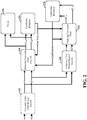
- FIG. 2 is a block diagram of apparatus that corrects for mismatches between I and Q signals using parallel correction paths, consistent with embodiments of the present disclosure.
- the block diagram in FIG. 2 explicitly shows two parallel correction paths that are consistent with the corresponding description from FIG. 1 .
- the frequency filter 202 can optionally be used to provide pre-filtering of the IQ signals (e.g., relative to the entire band of interest) and produces filtered I' and Q' signals.
- the first correction path provides the I'Q' signals to a first multiple-tap correction filter 204.
- the I' cor Q' cor output of the first multiple-tap correction filter 204 can be provided as an output 206 of the apparatus and used for decoding of data within the signals.
- the output of the first multiple-tap correction filter 204 is also provided to the first coefficient estimator 208.
- the first coefficient estimator 208 generates a first set of coefficients.
- the first set of coefficients are optimized relative to the full band of interest. Accordingly, the first set of coefficients can be used as the center tap for both the first multiple-tap correction filter 204 and the second multiple-tap correction filter 212.
- the second correction path filters out a portion of the entire band of interest using a frequency filter 210 to produce sub band I"Q" signals.
- the sub band I"Q" signals are provided to the second multiple-tap correction filter 212.
- the I" cor Q" cor output of the second multiple-tap correction filter 212 is provided to the second coefficient estimator 214 to produce the second set of coefficients for both the first multiple-tap correction filter 204 and the second multiple-tap correction filter 212.
- the feedback loop formed by the second coefficient estimator 214 and the second multiple-tap correction filter 212 produces a set of coefficients that attempt to minimize error within only a portion of the full signal band.
- FIG. 3 depicts a functional diagram of a circuit that corrects for mismatches between I and Q signals, consistent with embodiments of the present disclosure.
- Receiver front end circuitry 302 is depicted as multiplying an incoming RF signal using two multipliers 308 and 310.
- multiplier 308 corresponds to the in-phase (I) signal component
- multiplier 310 corresponds to the quadrature-phase (Q) signal component.
- the multipliers 308 and 310 are provided with a sine and cosine signal that have a phase difference of 90 degrees.
- the output of the multipliers are IQ signals at an intermediate frequency (IF).
- Optional filters 312 and 314 can provide frequency filtering for the IQ signals and can be implemented, for example, using bandpass filters (e.g., SAW filters).
- the IP signals are provided directly (with the entire frequency band of interest) to a first multiple-tap correction filter 304.
- an ADC can be used to first convert the analog signals into the digital domain.
- the first multiple-tap correction filter 304 has three taps (represented by delay components "T"). Each tap provides filtering according to a respective set of coefficients, a(n) and b(n). The coefficients represent an amplitude component, a(n), and a phase component b(n).
- the output of the first multiple-tap correction filter 304 is a corrected set of I'Q' signals that can be decoded to obtain the data within the received RF signal. The output is also provided to a first coefficient estimator 306.
- the first coefficient estimator 306 produces a first set of coefficients that includes an amplitude component a(2) and a phase component p(2).
- the components 324 and 328 take the absolute value of each of the I'Q' signals.
- Component (adder) 326 takes the difference between the absolute values. The difference is then integrated using integrator 334 to produce the amplitude coefficient a(2).
- the phase coefficient is determined by integrating, using integrator 332, a correlation between the I and Q signals, where the correlation is represented by the output of multiplier 330.
- the relative gains for amplifiers 331 and 333 can be used to set the speed and accuracy of the coefficient tracking (convergence) in the calibration system.
- the coefficients a(2) and b(2) set a constant correction factor over the IF frequency range.
- Bandpass (BP) filters 316 and 318 filter out a portion of the entire frequency band of interest for each of the I and Q signals, respectively.
- the bandpass filters 316 and 318 can be implemented using a mixer and low-pass filter combination.
- the depicted example of a bandpass filter has a bandpass of 9.232 MHz to 10 MHz, which corresponds to a 10 MHz IF signal with the full frequency bandwidth of interest being 1.53 MHz.
- the specific numbers for the bandpass filters are provided as an example and can be modified (e.g., in view of the center frequency and bandwidth of the IF signal).
- the second multiple-tap correction filter 320 is configured using the same coefficients as the first multiple-tap correction filter 304.
- the corrected output is provided to the second coefficient estimator 322, which is configured in the same manner as the first coefficient estimator 306.
- the set of coefficients generated by the second coefficient estimator 322 are used to set a second set of coefficients for both the first multiple-tap correction filter 304 and the second multiple-tap correction filter 320.
- the second coefficient estimator 322 generates amplitude coefficients a(1) and a(3) and phase coefficients p(1) and p(3), which correspond to the first and third taps.
- the coefficient estimators 306 and 322 are not meant to be limiting for every embodiment.
- the coefficient estimators can use alternative solutions to determine the correlation between the I and Q signals, as is relevant to the generation of the phase coefficients.
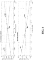
- FIG. 4 is a plot of the signal transfer for I and Q components with a single-tap compensation, consistent with embodiments of the present disclosure.
- the amplitude transfer (upper plot) and the phase transfer (lower plot) correspond to a situation in which the relative IQ mismatch varies across the depicted frequencies (-12 MHz to -0.8 MHz).
- the depicted frequencies are indicated as being negative, which is a notational convenience sometimes used when representing image frequencies.
- the corrective filtering from a single-tap compensation is able to correct for phase and amplitude mismatch relative to a particular frequency.
- the amplitude and phase transfer shows that the difference in I (402, 410) and Q (404, 408) transfer is zero at -10 MHz, as shown by 406 and 412, respectively. Both the amplitude and phase transfers deviate as frequencies diverges from the zero point at -10 MHz.
- the relative mismatch is mirrored on either side of the zero point 406, 412. This property can be exploited to reduce the processing to generate coefficients.
- the coefficients calculated for one half of the frequency band can be reused for the other half of the frequency band.
- the tilt of the I and Q transfer can be equalized. When the amplitude or phase coefficients are both positive, the transfer gets a negative tilt. When the coefficients are positive, the transfer get a positive tilt.
- FIG. 5 is a diagram showing signal spectrum for a single-tap compensation, consistent with embodiments of the present disclosure.
- the signal spectrum shown in FIG. 5 is generated using the phase and amplitude transfers from FIG. 4 .
- the portion 502 represents the image signal generated by the IQ mismatch without corrective filtering.
- the lower shaded portion 504 represents the image signal remaining after filtering using a single tap.
- the portion 506 shows the frequency components for the original signal.
- the single-tap correction shows an improvement over no compensation, but the residual image signal increases with the distance from the center point at -10 MHz.
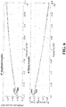
- FIG. 6 is a plot of the signal transfer for I and Q components with a three-tap compensation, consistent with embodiments of the present disclosure.
- the amplitude and phase transfers shown in FIG. 6 are with respect to a three tap correction filter in which the outside tap coefficients are generated relative to a frequency sub band of the full frequency band of interest.
- the mismatch between the I (604, 608)) and Q (602, 606) signal transfers is well match for the depicted frequency band.
- FIG. 7 is a diagram showing signal spectrum for a three-tap compensation, consistent with embodiments of the present disclosure.
- the frequency components at -10 MHz represent a signal image of signal 704 relative to IQ phase and amplitude mismatches.
- the frequency components identified by 702 show the image without compensation.
- the frequency components identified by 706 show the image with single-tap compensation.
- the frequency components indicated by 708 show the image with three-tap compensation, where the outer taps are designed to compensate for frequency dependency of the IQ mismatch, consistent with various embodiments discussed herein.
- FIG. 8 is a flow diagram for providing IQ mismatch compensation, consistent with embodiments of the present disclosure.
- the flow diagram begins with the receipt and optional filtering of in-phase (I) signal and a quadrature-phase (Q) signal having a first frequency bandwidth, per block 802.
- a frequency filter 102 can provide bandpass filtering relative to the full frequency band of interest.
- the flow diagram shows two separate paths after the receipt and optional filtering. As discussed herein, these paths can be followed in parallel or sequentially depending upon the particular implementation.
- the full frequency band IQ signals are corrected using a multiple-tap correction filter having a plurality of taps, per block 806.
- the correction can compensate for image components caused by mismatches between I and Q signals (although the filtering can also compensate for image components from other sources).
- the correction of the I and Q signals is accomplished using sets of coefficients for the plurality of taps.
- the corrected IQ signals are then used to generate a set coefficients, per block 810.
- each set of coefficients may include an amplitude coefficient and a phase coefficient.
- the set of coefficients are used to update the multiple-tap correction filter from the first path, per block 814.
- the set of coefficients are also used to update the multiple-tap correction filter from the second path. Consistent with various embodiments, a single multiple-tap correction filter can be reused for each path (e.g., by time interleaving the multiple-tap correction filter between each path).
- the second path begins by applying a frequency filter to the I and Q signals, per block 804.
- the frequency filter removes a portion of the full band of interest. In particular implementations, the frequency filter removes either an upper or lower half of the full band of interest.
- the filtered IQ signals are then corrected using a multiple-tap correction filter with the plurality of taps and corresponding coefficients, per block 808.
- Second and third sets of coefficients are generated based upon the output of the multiple-tap correction filter, per block 812. The second and third sets of coefficients are then used to update the multiple-tap correction filter(s), per block 814.
- circuits or circuitry which are discussed in the context of terms such as blocks, modules, and tasks. Such circuits or circuitry are used together with other elements.
- the circuit structure is exemplified through a discussion of the related embodiments and the corresponding structures, steps, functions, operations, activities, etc.
- one or more illustrated items in this context represent circuits (e.g., CPU circuits, discrete logic circuitry or (semi-)programmable circuits) configured and arranged for implementing these operations/activities, as may be carried out in the approaches shown in the figures.
- one or more computer processing circuits or CPUs are configured by way of memory circuitry that stores software code (program to be executed as a set/sets of instructions) for performing a specific set of operations.
- Certain embodiments are directed to a computer program product (e.g ., nonvolatile memory device), which includes a machine or computer-readable medium having stored thereon, instructions which may be executed by a computer (or other electronic device) that includes a computer processor circuit to perform these operations/activities.
- a computer program product e.g ., nonvolatile memory device
- these instructions reflect activities or data flows as may be consistent with the figures, flow charts, and the detailed description.
Landscapes
- Engineering & Computer Science (AREA)
- Power Engineering (AREA)
- Computer Networks & Wireless Communication (AREA)
- Signal Processing (AREA)
- Digital Transmission Methods That Use Modulated Carrier Waves (AREA)
Abstract
Description
- Aspects of various embodiments are directed to the use of calibration of a multiple-tap compensation circuit.
- Radio frequency (RF) circuits are often designed to use an encoding scheme in which the transmitted RF signal includes In-phase (I) and Quadrature-phase (Q) components. The receiver circuit mixes a received RF signal with a sine and cosine wave, producing separate I and Q signals. The receiver circuit might also use heterodyning to produce an intermediate frequency (IF) signal that is further processed by amplifiers, filters and Analog-to-Digital Converters (ADCs).
- These and other matters have presented challenges to circuits providing signal communications and related implementations, for a variety of applications.
- Various example embodiments are directed to issues such as those addressed above and/or others which may become apparent from the following disclosure concerning compensating for IQ mismatches.
- In certain example embodiments, aspects of the present disclosure involve compensating for IQ mismatches that exhibit frequency dependence.
- Consistent with various embodiments, an apparatus corrects for mismatches between an in-phase (I) signal and a quadrature-phase (Q) signal, the I and Q signals having a first frequency band. The apparatus includes a frequency filter circuit configured to filter the I and Q signals to produce a filtered I and Q output with a second frequency band that is a subset of the first frequency band. The apparatus also includes digital circuitry, which includes a multiple-tap correction filter having a plurality of taps and configured to generate I and Q output signals by filtering the I and Q signals according to respective sets of coefficients for the plurality of taps. The digital circuitry also includes a coefficient estimator configured to generate, from the I and Q signals having the first frequency band, a first set of coefficients for the sets of coefficients; and generate, from the filtered I and Q signals having the second frequency band, second and third sets of coefficients for the sets of coefficients.
- Various embodiments are directed toward a method involving the receipt of an in-phase (I) signal and a quadrature-phase (Q) signal having a first frequency bandwidth. A multiple-tap correction filter having a plurality of taps is used to correct mismatches in the I and Q signals by filtering the I and Q signals according to sets of coefficients for the plurality of taps. The I and Q signals are filtered to produce filtered I and Q signals having a second frequency band that is a subset of the first frequency band. The multiple-tap correction filter is used to correct mismatches in the filtered I and Q signals by filtering the filtered I and Q output according to the respective sets of coefficients. The corrected I and Q signals having the first frequency bandwidth are used to generate a first set of coefficients for the sets of coefficients. The corrected I and Q signals having the second frequency bandwidth are used to generate second and third sets of coefficients for the sets of coefficients.
- The above discussion/summary is not intended to describe each embodiment or every implementation of the present disclosure. The figures and detailed description that follow also exemplify various embodiments.
- Various example embodiments may be more completely understood in consideration of the following detailed description in connection with the accompanying drawings, in which:
-
FIG. 1 is a block diagram of apparatus that corrects for mismatches between I and Q signals, consistent with embodiments of the present disclosure; -
FIG. 2 is a block diagram of apparatus that corrects for mismatches between I and Q signals using parallel correction paths, consistent with embodiments of the present disclosure; -
FIG. 3 depicts a functional diagram of a circuit that corrects for mismatches between I and Q signals, consistent with embodiments of the present disclosure; -
FIG. 4 is a plot of the signal transfer for I and Q components with a single-tap compensation, consistent with embodiments of the present disclosure; -
FIG. 5 is a diagram showing signal spectrum for a single-tap compensation, consistent with embodiments of the present disclosure; -
FIG. 6 is a plot of the signal transfer for I and Q components with a three-tap compensation, consistent with embodiments of the present disclosure; -
FIG. 7 is a diagram showing signal spectrum for a three-tap compensation, consistent with embodiments of the present disclosure; and -
FIG. 8 is a flow diagram for providing IQ mismatch compensation, consistent with embodiments of the present disclosure. - While various embodiments discussed herein are amenable to modifications and alternative forms, aspects thereof have been shown by way of example in the drawings and will be described in detail. It should be understood, however, that the intention is not to limit the disclosure to the particular embodiments described. On the contrary, the intention is to cover all modifications, equivalents, and alternatives falling within the scope of the disclosure including aspects defined in the claims. In addition, the term "example" as used throughout this application is only by way of illustration, and not limitation.
- Aspects of the present disclosure are believed to be applicable to a variety of different types of apparatuses, systems and methods involving filtering by RF receiver circuits. In certain implementations, aspects of the present disclosure have been shown to be beneficial when used in the context of multiple-tap filters to compensate for errors due to mismatches between I and Q signal components. In some embodiments, a multiple-tap filter can provide image filtering that compensates for I and Q mismatches that vary over a desired frequency bandwidth. While not necessarily so limited, various aspects may be appreciated through the following discussion of non-limiting examples which use exemplary contexts.
- Accordingly, in the following description various specific details are set forth to describe specific examples presented herein. It should be apparent to one skilled in the art, however, that one or more other examples and/or variations of these examples may be practiced without all the specific details given below. In other instances, well known features have not been described in detail so as not to obscure the description of the examples herein. For ease of illustration, the same reference numerals may be used in different diagrams to refer to the same elements or additional instances of the same element. Also, although aspects and features may in some cases be described in individual figures, it will be appreciated that features from one figure or embodiment can be combined with features of another figure or embodiment even though the combination is not explicitly shown or explicitly described as a combination.
- Various embodiments of the present disclosure are directed toward a multiple-tap frequency filter and toward finding sets of coefficients for the multiple-tap frequency filter. In particular implementations, the coefficients are set to compensate for frequency dependency in I and Q mismatches, relative to a frequency band of interest.
- Elements like mixers, IF filters, amplifiers and ADCs can introduce an amplitude and phase difference between I and Q paths. Ideally, the amplitude for the I path should be the same as the amplitude for the Q path (accounting for differences due to modulation). Further, the phase between I and Q paths should be 90°. Deviations from the ideal situation degrade Image Rejection (IR) performance. IR can be improved by applying a digital correction algorithms. Aspects of the present disclosure are directed toward implementations in which the amplitude and phase errors exhibit non-trivial frequency dependence over a signal bandwidth of interest. Various embodiments are directed toward compensation that considers frequency dependence of the amplitude and phase errors between I and Q paths.
- Various embodiments are directed toward generating tap coefficients for a multiple-tap finite-impulse response (FIR) filter that corrects for IQ mismatch or imbalance. Each set of tap coefficients corresponds to a respective tap and includes a phase component and gain component. According to particular implementations, the output of the multiple-tap filter is connected to a coefficient estimator that generates a first set of tap coefficients in response to IQ mismatches in the received IQ signals and relative to the entire frequency band of interest. The first set of coefficients is used to update a tap of the multiple-tap filter. The updating occurs as part of a feedback loop that attempts to minimize undesired signal image caused by the IQ mismatch relative to the entire frequency band of interest. By implementing minimization relative to the entire frequency band, the compensation can be less effective at certain frequencies (e.g., for frequencies near the edges of the frequency band of interest).
- To improve compensation across the frequency band of interest, additional sets of tap coefficients are generated for use by the multiple-tap filter. Consistent with particular embodiments, the additional sets of tap coefficients are generated by applying a frequency filter to the IQ signals to produce IQ signals that have a frequency band that is a subset of the IQ entire frequency band, which was used to generate the first set of coefficients for the first tap. The resulting additional sets of tap coefficients are thereby targeted at minimizing undesired signal images caused by the IQ mismatch relative to a sub band of the entire frequency band of interest. The combination of the multiple sets of tap coefficients can be particularly useful for compensating for frequency dependency with IQ mismatches.
- According to particular embodiments of the present disclosure, the coefficient estimator(s) are configured to generate the sets of tap coefficients using a relatively computationally simple algorithm (e.g., without the need for a computationally intensive inverse fast Fourier transform). For instance, the coefficient estimator can use a combination of relatively simple functions (e.g., adders, multipliers and integrators) to generate phase and gain components of the tap coefficients.
- Certain aspects of the present disclosure relate to the recognition that proper optimization of the first set of tap coefficients (based upon the entire signal band of interest) leads to an average error that is zero. This can occur due to residual error remaining, but being cancelled out by the coefficient estimator and feedback loop (e.g., when the system operates as a closed loop with an integrator in the feedback path). It has been further recognized that, for image components caused by IQ mismatch, the residual error can be (near) zero at a center point for the entire band of interest. The result is that the phase and amplitude errors on either side of the center point cancel each other out because they have equal magnitudes and opposites signs. Accordingly, certain embodiments are directed toward the use of a single coefficient estimator to produce coefficients for two different sets of tap coefficients, each set corresponding to a respective side of the center point. For example, a bandpass filter can be used to filter half of the entire frequency band of interest (on either side of the center point). A set of coefficients generated for this sub band can be used for taps on respective sides of a center tap of the multiple-tap filter.
- Turning now to the figures,
FIG. 1 is a block diagram of apparatus that corrects for mismatches between I and Q signals, consistent with embodiments of the present disclosure. The apparatus ofFIG. 1 can be implemented as part of a receiver or transceiver circuit that can perform various pre-processing of a received RF signal to produce the depicted I and Q signals. For example, the preprocessing can include mixing a received RF signal with reference signals that are 90 degrees out of phase (e.g., sine and cosine wave) to produce separate I and Q signals. The receiver circuit might also use heterodyning to shift the frequency of the RF signal to produce an intermediate frequency (IF) signal. In certain embodiments, the signal processing can include the use of afrequency filter 102 that filters out frequencies outside of the full frequency band of interest. As a non-limiting example,frequency filter 102 can be a surface acoustic wave (SAW) filter. Thefrequency filter 102 is optional and not required for each implementation. - A
frequency filter 104 filters the I and Q signals relative to a sub band of the full frequency band of interest. As discussed herein, particular embodiments are directed toward thefrequency filter 104 being configured to filter half of the full frequency band of interest. For example, if the full frequency band of interest is based upon a modulated signal at 10 MHz (IF) and having a bandwidth of 1.53 MHz, then the frequency filter can be implemented as a bandpass filter for either 9.232 MHz to 10 MHz or 10 MHz to 10.768 MHz. Thefrequency filter 104 can be implemented in either the analog realm or the digital realm. - The output of the
frequency filter 104 is provided to a multiple-tap correction filter 106. The multiple-tap correction filter 106 compensates for image components resulting from IQ mismatches, which can be caused by mismatches in the preprocessing and filtering of the RF signal and the IQ signals generated therefrom. The output of the multiple-tap correction filter 106 (Icor and Qcor) is provided as anoutput 108, which can be used to decode data that was encoded within the RF signal. The output of the multiple-tap correction filter 106 is also provided to thecoefficient estimator 110, which generates sets of coefficient values for the taps of the multiple-tap correction filter 106. The resulting feedback loop converges to minimize the image error in the IQ signals. - The operation of the multiple-
tap correction filter 106 is defined by sets of coefficients that each configure a corresponding tap. The apparatus ofFIG .1 sets of coefficients set to compensate for frequency dependence of the IQ mismatch. This can be accomplished by generating a first set of coefficients from the full frequency band of interest and additional (second and third) sets of coefficients from a partial sub band of the fully frequency band of interest. In order to create these different sets of coefficients, the coefficient estimator receives two version of the corrected IQ signals. The first version is generated by applying the correction filtering to IQ signals containing the full frequency band of interest. The second version is generated by applying the same correction filtering to IQ signals that have had a portion of the full frequency band filtered out (e.g., ½ of the full frequency band has been removed from the IQ signals before correction filtering). - According to certain embodiments of the present disclosure, the IQ signal correction filtering of the respective frequency bands (e.g., full and half) is accomplished using the same multiple-
tap correction filter 106. For example, frequency andcoefficient selection logic 112 can be configured to select between the respective frequency bands. When the full frequency band is selected, theselection logic 112 can disable orbypass frequency filter 104. As an alternative to completely bypassing or disabling thefrequency filter 104, the bandwidth of thefrequency filter 104 could be adjusted so as not to filter out frequencies within the full band of interest. The output of the multiple-tap correction filter 106 can then be provided both to theoutput 108 and thecoefficient estimator 110. The set of coefficients generated by thecoefficient estimator 110 can be used to update a first tap of multiple-tap correction filter 106. As discussed herein, this first tap can correspond to the center tap of a multiple-tap correction filter 106 with an odd number of taps. - When the sub (half) frequency band is selected, the
selection logic 112 can enablefrequency filter 104 so that the multiple-tap correction filter 106 receives only a portion of the full IQ signal. The output of the multiple-tap correction filter 106 can then be provided to thecoefficient estimator 110. Theselection logic 112 can prevent the output of the multiple-tap correction filter 106 from being provided to theoutput 108. In particular, the multiple-tap correction filter 106 output represents only a portion of the full IQ signal. The resulting signal may still contain residual errors that can make proper decoded difficult or impossible. The set of coefficients generated by thecoefficient estimator 110 can be used to update additional taps of multiple-tap correction filter 106. As discussed herein, the additional tap can correspond to taps on either side of the center tap of a multiple-tap correction filter 106 (e.g., taps one and three in a three-tap filter). According to embodiments, thecoefficient estimator 110 can use the same coefficient value for each of the corresponding taps. Theselection logic 112 can control which tap(s) the output of thecoefficient estimator 110 is used to update based upon the corresponding setting for thefrequency filter 104. - According to various embodiments,
frequency filter 104, multiple-tap correction filter 106, thecoefficient estimator 110, andselection logic 112 are implemented in the digital realm using a processor circuit and a memory circuit. An ADC can be located before thefrequency filter 104 to produce digital data representing the IQ signals. As an example, a digital signal processor (DSP) chip can be programmed to implement thefrequency filter 104, multiple-tap correction filter 106, thecoefficient estimator 110, andselection logic 112. In this context, the reuse of the multiple-tap correction filter 106 and thecoefficient estimator 110 for the different frequency bands represents as time-interleaving of the processing time for implementing relative to the corresponding frequency band. For example, a DSP could implement an initialization phase before data is decoded. During the initializing phase, values for the first set of coefficients can first be determined relative to the entire frequency band of interest. Once the values have settled for the first set of coefficients, the DSP enables thefrequency filter 104 and obtains the second set of coefficients relative to a subset of the frequency band of interest. At the completion of the initialization phase, the DSP disables thefrequency filter 104 and the data encoded in the IQ signals can be decoded. - According to certain embodiments, the DSP may also update the second set of coefficients at subsequent points of operation. Different triggering events can be used to determine when the values are updated. For example, the communication protocol may have periods during which data is not actively being transmitted. The DSP can use these periods to update the values for the second set of coefficients. The DSP might also periodically perform updates. As another example, the system could be configured to update the values in response to detecting errors in the decoded data (e.g., in response to a bit error rate exceeding a threshold value). These and other triggering events can be used alone or in various combinations.
- According to certain embodiments, the system is configured to update the second set of coefficients while simultaneously providing corrected IQ signals for decoding. In particular, the full frequency band IQ signal is corrected by a multiple-
tap correction filter 106 at the same time as the sub frequency band IQ signal is corrected by a multiple-tap correction filter 106. The corrected outputs are each provided to acoefficient estimator 110 to generate the corresponding sets of coefficients. The effect is two parallel processing paths for the same IQ signal. The parallel nature of the processing paths is understood in the context of the relative timing of the IQ signals being processed, and is not limited to simultaneous processing time within separate circuits (e.g., the same processor circuit(s) of a DSP could be used to implement each path using time-interleaving). - For ease of discussion various embodiments are discussed in the context of a three-tap correction filter. Notwithstanding, it is recognized that the number of taps can be increased beyond three and that such modification may further improve the correction capabilities of the circuit. For example, an additional frequency filter can be used to remove half of the sub frequency band of
frequency filter 104. The multiple-tap correction filter can be applied to the resulting IQ signals and a coefficient estimator can generate additional sets of tap coefficients from the corrected signals. The use of additional taps can be particularly useful for wide frequency bands of interest and for IQ mismatches that exhibit a strong dependence on frequency. -
FIG. 2 is a block diagram of apparatus that corrects for mismatches between I and Q signals using parallel correction paths, consistent with embodiments of the present disclosure. The block diagram inFIG. 2 explicitly shows two parallel correction paths that are consistent with the corresponding description fromFIG. 1 . Thefrequency filter 202 can optionally be used to provide pre-filtering of the IQ signals (e.g., relative to the entire band of interest) and produces filtered I' and Q' signals. - The first correction path provides the I'Q' signals to a first multiple-
tap correction filter 204. The I'cor Q'cor output of the first multiple-tap correction filter 204 can be provided as anoutput 206 of the apparatus and used for decoding of data within the signals. The output of the first multiple-tap correction filter 204 is also provided to thefirst coefficient estimator 208. Thefirst coefficient estimator 208 generates a first set of coefficients. The first set of coefficients are optimized relative to the full band of interest. Accordingly, the first set of coefficients can be used as the center tap for both the first multiple-tap correction filter 204 and the second multiple-tap correction filter 212. - The second correction path filters out a portion of the entire band of interest using a
frequency filter 210 to produce sub band I"Q" signals. The sub band I"Q" signals are provided to the second multiple-tap correction filter 212. The I"cor Q"cor output of the second multiple-tap correction filter 212 is provided to thesecond coefficient estimator 214 to produce the second set of coefficients for both the first multiple-tap correction filter 204 and the second multiple-tap correction filter 212. The feedback loop formed by thesecond coefficient estimator 214 and the second multiple-tap correction filter 212 produces a set of coefficients that attempt to minimize error within only a portion of the full signal band. -
FIG. 3 depicts a functional diagram of a circuit that corrects for mismatches between I and Q signals, consistent with embodiments of the present disclosure.FIG. 3 provides a more specific example for the components discussed in connection withFIGs. 1 and2 , consistent with certain embodiments. Receiverfront end circuitry 302 is depicted as multiplying an incoming RF signal using twomultipliers multiplier 308 corresponds to the in-phase (I) signal component andmultiplier 310 corresponds to the quadrature-phase (Q) signal component. Although note depicted, themultipliers Optional filters - The IP signals are provided directly (with the entire frequency band of interest) to a first multiple-
tap correction filter 304. In many instances, an ADC can be used to first convert the analog signals into the digital domain. The first multiple-tap correction filter 304 has three taps (represented by delay components "T"). Each tap provides filtering according to a respective set of coefficients, a(n) and b(n). The coefficients represent an amplitude component, a(n), and a phase component b(n). The output of the first multiple-tap correction filter 304 is a corrected set of I'Q' signals that can be decoded to obtain the data within the received RF signal. The output is also provided to afirst coefficient estimator 306. - The
first coefficient estimator 306 produces a first set of coefficients that includes an amplitude component a(2) and a phase component p(2). Thecomponents integrator 334 to produce the amplitude coefficient a(2). The phase coefficient is determined by integrating, usingintegrator 332, a correlation between the I and Q signals, where the correlation is represented by the output ofmultiplier 330. The relative gains foramplifiers 331 and 333 can be used to set the speed and accuracy of the coefficient tracking (convergence) in the calibration system. The coefficients a(2) and b(2) set a constant correction factor over the IF frequency range. - Bandpass (BP) filters 316 and 318 filter out a portion of the entire frequency band of interest for each of the I and Q signals, respectively. As a non-limiting example, the
bandpass filters - The second multiple-
tap correction filter 320 is configured using the same coefficients as the first multiple-tap correction filter 304. The corrected output is provided to thesecond coefficient estimator 322, which is configured in the same manner as thefirst coefficient estimator 306. The set of coefficients generated by thesecond coefficient estimator 322 are used to set a second set of coefficients for both the first multiple-tap correction filter 304 and the second multiple-tap correction filter 320. In particular, thesecond coefficient estimator 322 generates amplitude coefficients a(1) and a(3) and phase coefficients p(1) and p(3), which correspond to the first and third taps. - The particular configurations of the multiple-tap correction filters 304 and 320 and of the
coefficient estimators -
FIG. 4 is a plot of the signal transfer for I and Q components with a single-tap compensation, consistent with embodiments of the present disclosure. The amplitude transfer (upper plot) and the phase transfer (lower plot) correspond to a situation in which the relative IQ mismatch varies across the depicted frequencies (-12 MHz to -0.8 MHz). The depicted frequencies are indicated as being negative, which is a notational convenience sometimes used when representing image frequencies. The corrective filtering from a single-tap compensation is able to correct for phase and amplitude mismatch relative to a particular frequency. The amplitude and phase transfer shows that the difference in I (402, 410) and Q (404, 408) transfer is zero at -10 MHz, as shown by 406 and 412, respectively. Both the amplitude and phase transfers deviate as frequencies diverges from the zero point at -10 MHz. - The relative mismatch is mirrored on either side of the zero
point 406, 412. This property can be exploited to reduce the processing to generate coefficients. In particular, the coefficients calculated for one half of the frequency band (either above or below -10 MHz) can be reused for the other half of the frequency band. By setting the coefficients for the outer tap values in this manner, the tilt of the I and Q transfer can be equalized. When the amplitude or phase coefficients are both positive, the transfer gets a negative tilt. When the coefficients are positive, the transfer get a positive tilt. -
FIG. 5 is a diagram showing signal spectrum for a single-tap compensation, consistent with embodiments of the present disclosure. The signal spectrum shown inFIG. 5 is generated using the phase and amplitude transfers fromFIG. 4 . Theportion 502 represents the image signal generated by the IQ mismatch without corrective filtering. The lowershaded portion 504 represents the image signal remaining after filtering using a single tap. Theportion 506 shows the frequency components for the original signal. The single-tap correction shows an improvement over no compensation, but the residual image signal increases with the distance from the center point at -10 MHz. -
FIG. 6 is a plot of the signal transfer for I and Q components with a three-tap compensation, consistent with embodiments of the present disclosure. The amplitude and phase transfers shown inFIG. 6 are with respect to a three tap correction filter in which the outside tap coefficients are generated relative to a frequency sub band of the full frequency band of interest. The mismatch between the I (604, 608)) and Q (602, 606) signal transfers is well match for the depicted frequency band. -
FIG. 7 is a diagram showing signal spectrum for a three-tap compensation, consistent with embodiments of the present disclosure. The frequency components at -10 MHz represent a signal image ofsignal 704 relative to IQ phase and amplitude mismatches. The frequency components identified by 702 show the image without compensation. The frequency components identified by 706 show the image with single-tap compensation. The frequency components indicated by 708 show the image with three-tap compensation, where the outer taps are designed to compensate for frequency dependency of the IQ mismatch, consistent with various embodiments discussed herein. -
FIG. 8 is a flow diagram for providing IQ mismatch compensation, consistent with embodiments of the present disclosure. The flow diagram begins with the receipt and optional filtering of in-phase (I) signal and a quadrature-phase (Q) signal having a first frequency bandwidth, perblock 802. For example, afrequency filter 102 can provide bandpass filtering relative to the full frequency band of interest. The flow diagram shows two separate paths after the receipt and optional filtering. As discussed herein, these paths can be followed in parallel or sequentially depending upon the particular implementation. In the first path, the full frequency band IQ signals are corrected using a multiple-tap correction filter having a plurality of taps, perblock 806. The correction can compensate for image components caused by mismatches between I and Q signals (although the filtering can also compensate for image components from other sources). The correction of the I and Q signals is accomplished using sets of coefficients for the plurality of taps. The corrected IQ signals are then used to generate a set coefficients, perblock 810. As discussed herein, each set of coefficients may include an amplitude coefficient and a phase coefficient. The set of coefficients are used to update the multiple-tap correction filter from the first path, perblock 814. The set of coefficients are also used to update the multiple-tap correction filter from the second path. Consistent with various embodiments, a single multiple-tap correction filter can be reused for each path (e.g., by time interleaving the multiple-tap correction filter between each path). - The second path begins by applying a frequency filter to the I and Q signals, per
block 804. The frequency filter removes a portion of the full band of interest. In particular implementations, the frequency filter removes either an upper or lower half of the full band of interest. The filtered IQ signals are then corrected using a multiple-tap correction filter with the plurality of taps and corresponding coefficients, perblock 808. Second and third sets of coefficients are generated based upon the output of the multiple-tap correction filter, perblock 812. The second and third sets of coefficients are then used to update the multiple-tap correction filter(s), perblock 814. - Terms to that indicate orientation, such as upper/lower, left/right, top/bottom and above/below, may be used herein to refer to relative positions of elements as shown in the figures. It should be understood that when the terminology is used for notational convenience, the disclosed structures may be oriented different from the orientation shown in the figures.
- The Specification describes and/or illustrates aspects useful for implementing the claimed disclosure by way of various circuits or circuitry which are discussed in the context of terms such as blocks, modules, and tasks. Such circuits or circuitry are used together with other elements. The circuit structure is exemplified through a discussion of the related embodiments and the corresponding structures, steps, functions, operations, activities, etc. For example, in certain of the above-discussed embodiments, one or more illustrated items in this context represent circuits (e.g., CPU circuits, discrete logic circuitry or (semi-)programmable circuits) configured and arranged for implementing these operations/activities, as may be carried out in the approaches shown in the figures. In certain embodiments, one or more computer processing circuits or CPUs are configured by way of memory circuitry that stores software code (program to be executed as a set/sets of instructions) for performing a specific set of operations.
- Certain embodiments are directed to a computer program product (e.g., nonvolatile memory device), which includes a machine or computer-readable medium having stored thereon, instructions which may be executed by a computer (or other electronic device) that includes a computer processor circuit to perform these operations/activities. For example, these instructions reflect activities or data flows as may be consistent with the figures, flow charts, and the detailed description.
Claims (15)
- An apparatus to correct for mismatches between an in-phase (I) signal and a quadrature-phase (Q) signal, the I and Q signals having a first frequency band, the apparatus comprising:a frequency filter circuit (202) configured to filter the I and Q signals to produce a filtered I and Q output with a second frequency band that is a subset of the first frequency band;a digital circuitry that includes:a multiple tap correction filter (204) having a plurality of taps and configured to generate I and Q output signals by filtering the I and Q signals according to respective sets of coefficients for the plurality of taps;a coefficient estimator (208) configured togenerate, from the I and Q signals having the first frequency band, a first set of coefficients for the sets of coefficients; andgenerate, from the filtered I and Q signals having the second frequency band, second and third sets of coefficients for the sets of coefficients.
- The apparatus of claim 1, wherein each set of coefficients includes a phase component and a gain component.
- The apparatus of claim 1 or 2, wherein the coefficient estimator (208) is further configured to generate respective phase components by determining a phase correlation between I and Q signals and integrating the determined phase correlation.
- The apparatus of any of preceding claim, wherein the coefficient estimator (208) is further configured to generate respective gain components by determining an absolute difference in amplitude of I and Q signals and integrating the determined absolute difference.
- The apparatus of any of preceding claim, wherein the second frequency band is half of the first frequency band.
- The apparatus of any preceding claim, wherein the coefficient estimator (208) is further configured to generate, from the filtered I and Q signals having the second frequency band, a single phase component and a single gain component that is used for sets of coefficients one both sides of at tap corresponding to the first set of coefficients.
- The apparatus of any preceding claim, further comprising an analog-to-digital converter (ADC) circuit configured to convert the I and Q signals to a digital signal that is provided to the frequency filter circuit (202).
- The apparatus of claim 7, further comprising a surface acoustic wave filter configured to filter the I and Q signals according to the first frequency band and to provide an output to the ADC.
- The apparatus of any preceding claim 1, wherein the digital circuitry is part of a digital signal processor (DSP).
- A method comprising:receiving an in-phase (I) signal and a quadrature-phase (Q) signal having a first frequency bandwidth;correcting, using a multiple-tap correction filter (204) having a plurality of taps, mismatches in the I and Q signals by filtering the I and Q signals according to sets of coefficients for the plurality of taps;filtering the I and Q signals to produce filtered I and Q signals having a second frequency band that is a subset of the first frequency band;correcting, using the multiple-tap correction filter (204), mismatches in the filtered I and Q signals by filtering the filtered I and Q output according to the respective sets of coefficients;generating, from the corrected I and Q signals having the first frequency bandwidth, a first set of coefficients for the sets of coefficients; andgenerating, from the corrected I and Q signals having the second frequency bandwidth, second and third sets of coefficients for the sets of coefficients.
- The method of claim 10, wherein each set of coefficients includes a phase component and a gain component.
- The method of claim 10 or 11, further comprising generating respective phase components by determining a phase correlation between respective I and Q signals and integrating the determined phase correlation.
- The method of any of the preceding claims 10 to 12, further comprising generating respective gain components by determining an absolute difference in amplitude of respective I and Q signals and integrating the determined amplitude.
- The method of any of the preceding claims 10 to 13, wherein the second frequency band is half of the first frequency band.
- A computer program including a machine or computer-readable medium having stored thereon, instructions to be executed by a computer (or other electronic device) that includes a computer processor circuit to perform the method of any of the preceding claims 10 to 14.
Applications Claiming Priority (1)
| Application Number | Priority Date | Filing Date | Title |
|---|---|---|---|
| US15/275,968 US9906384B1 (en) | 2016-09-26 | 2016-09-26 | Multiple-tap compensation and calibration |
Publications (2)
| Publication Number | Publication Date |
|---|---|
| EP3300250A1 true EP3300250A1 (en) | 2018-03-28 |
| EP3300250B1 EP3300250B1 (en) | 2021-05-26 |
Family
ID=59997042
Family Applications (1)
| Application Number | Title | Priority Date | Filing Date |
|---|---|---|---|
| EP17190369.3A Active EP3300250B1 (en) | 2016-09-26 | 2017-09-11 | Multiple-tap iq compensation and calibration |
Country Status (2)
| Country | Link |
|---|---|
| US (1) | US9906384B1 (en) |
| EP (1) | EP3300250B1 (en) |
Families Citing this family (3)
| Publication number | Priority date | Publication date | Assignee | Title |
|---|---|---|---|---|
| US10412698B2 (en) * | 2017-02-22 | 2019-09-10 | Samsung Electronics Co., Ltd. | System and method for IQ mismatch calibration and compensation |
| US10958483B1 (en) * | 2019-09-10 | 2021-03-23 | Huawei Technologies Co., Ltd. | Method and apparatus for determining a set of optimal coefficients |
| US20260066919A1 (en) * | 2024-09-04 | 2026-03-05 | Nxp B.V. | High-Speed Continuous-Time Delta-Sigma Modulator Including an Amplifier with Limited Gain |
Citations (5)
| Publication number | Priority date | Publication date | Assignee | Title |
|---|---|---|---|---|
| WO2004082232A1 (en) * | 2003-03-12 | 2004-09-23 | Koninklijke Philips Electronics N.V. | Transceiver with i/q mismatch compensation scheme |
| US20100215125A1 (en) * | 2009-02-25 | 2010-08-26 | Harris Corporation | Communications device with in-phase/quadrature (i/q) dc offset, gain and phase imbalance compensation and related method |
| US20110222638A1 (en) * | 2010-03-12 | 2011-09-15 | Chester Park | Frequency-dependent iq imbalance estimation |
| US20140029700A1 (en) * | 2012-07-27 | 2014-01-30 | Texas Instruments Incorporated | Multi-tap iq imbalance estimation and correction circuit and method |
| EP2894823A1 (en) * | 2014-01-10 | 2015-07-15 | Nxp B.V. | Coefficient estimation for digital IQ calibration |
Family Cites Families (8)
| Publication number | Priority date | Publication date | Assignee | Title |
|---|---|---|---|---|
| TWI256204B (en) * | 2004-01-09 | 2006-06-01 | Realtek Semiconductor Corp | Method and apparatus of IQ mismatch calibration |
| KR100710088B1 (en) * | 2006-02-23 | 2007-04-20 | 지씨티 세미컨덕터 인코포레이티드 | Receiving Circuits and Methods for Compensating IP Mismatch |
| US7957476B2 (en) * | 2006-05-16 | 2011-06-07 | Sony Corporation | Wireless communicaton apparatus |
| KR100793059B1 (en) * | 2006-11-14 | 2008-01-10 | 한국전자통신연구원 | Apparatus and method for receiving multiband signal in multimode |
| US8385457B2 (en) * | 2009-09-23 | 2013-02-26 | Intel Corporation | Methods and systems to compensate IQ imbalance in wideband zero-if tuners |
| US8427366B2 (en) * | 2010-07-27 | 2013-04-23 | Texas Instruments Incorporated | Dual frequency receiver with single I/Q IF pair and mixer |
| JP6176238B2 (en) * | 2012-03-01 | 2017-08-09 | 日本電気株式会社 | Digital signal processing device, receiving device, and signal transmission / reception system |
| US9100078B2 (en) * | 2012-04-10 | 2015-08-04 | Mediatek Inc. | RF receiver and digitally-assisted calibration method applicable thereto |
-
2016
- 2016-09-26 US US15/275,968 patent/US9906384B1/en not_active Expired - Fee Related
-
2017
- 2017-09-11 EP EP17190369.3A patent/EP3300250B1/en active Active
Patent Citations (5)
| Publication number | Priority date | Publication date | Assignee | Title |
|---|---|---|---|---|
| WO2004082232A1 (en) * | 2003-03-12 | 2004-09-23 | Koninklijke Philips Electronics N.V. | Transceiver with i/q mismatch compensation scheme |
| US20100215125A1 (en) * | 2009-02-25 | 2010-08-26 | Harris Corporation | Communications device with in-phase/quadrature (i/q) dc offset, gain and phase imbalance compensation and related method |
| US20110222638A1 (en) * | 2010-03-12 | 2011-09-15 | Chester Park | Frequency-dependent iq imbalance estimation |
| US20140029700A1 (en) * | 2012-07-27 | 2014-01-30 | Texas Instruments Incorporated | Multi-tap iq imbalance estimation and correction circuit and method |
| EP2894823A1 (en) * | 2014-01-10 | 2015-07-15 | Nxp B.V. | Coefficient estimation for digital IQ calibration |
Also Published As
| Publication number | Publication date |
|---|---|
| EP3300250B1 (en) | 2021-05-26 |
| US9906384B1 (en) | 2018-02-27 |
Similar Documents
| Publication | Publication Date | Title |
|---|---|---|
| CN107592279B (en) | IQ mismatch correction module | |
| KR102500150B1 (en) | Method and apparatus for low-complexity frequency dependent iq imbalance compensation | |
| US9893924B2 (en) | Module for a radio receiver | |
| US6115419A (en) | Adaptive digital beamforming receiver with π/2 phase shift to improve signal reception | |
| US9431962B2 (en) | Coefficient estimation for digital IQ calibration | |
| EP3300250B1 (en) | Multiple-tap iq compensation and calibration | |
| US20060203901A1 (en) | Apparatus and method for correcting IQ imbalance | |
| US20170264325A1 (en) | Outdoor unit resonator correction | |
| US20140179254A1 (en) | Carrier frequency offset compensation apparatus and associated method | |
| KR20050030422A (en) | Appratus and its method for i/q imbalance compensation by using variable loop gain in demodulator | |
| CN101208921B (en) | Radio receiving apparatus | |
| US8724752B2 (en) | Amplitude/orthogonality error compensator | |
| JPH11284677A (en) | Demodulator and digital radio communication system using it | |
| CN106850088B (en) | Radio frequency receiver and digital auxiliary correction method thereof | |
| US8787860B2 (en) | Image cancellation in receivers using dual adaptive filters | |
| US8666002B2 (en) | Receiver for compensating I/Q mismatch, compensation device, compensation module and compensation parameter calculating module | |
| US7522899B1 (en) | Image rejection scheme for receivers | |
| US9094079B2 (en) | System and method for I-Q imbalance correction | |
| CN116232558A (en) | A kind of IQ delay compensation method, device, electronic equipment and storage medium | |
| WO2015142479A1 (en) | Phase imbalance calibration | |
| US7109787B2 (en) | High-efficiency circuit for demodulating carriers in quadrature | |
| JP2004266416A (en) | Receiving machine | |
| US7672655B1 (en) | Frequency-selective and adaptive I/Q mismatch digital compensation | |
| US20030236073A1 (en) | Correction of mismatch between in-phase and quadrature signals in a radio receiver | |
| CN107204790A (en) | Apparatus and method for providing the real-time second order input intercept point calibration of background |
Legal Events
| Date | Code | Title | Description |
|---|---|---|---|
| PUAI | Public reference made under article 153(3) epc to a published international application that has entered the european phase |
Free format text: ORIGINAL CODE: 0009012 |
|
| STAA | Information on the status of an ep patent application or granted ep patent |
Free format text: STATUS: THE APPLICATION HAS BEEN PUBLISHED |
|
| AK | Designated contracting states |
Kind code of ref document: A1 Designated state(s): AL AT BE BG CH CY CZ DE DK EE ES FI FR GB GR HR HU IE IS IT LI LT LU LV MC MK MT NL NO PL PT RO RS SE SI SK SM TR |
|
| AX | Request for extension of the european patent |
Extension state: BA ME |
|
| STAA | Information on the status of an ep patent application or granted ep patent |
Free format text: STATUS: REQUEST FOR EXAMINATION WAS MADE |
|
| 17P | Request for examination filed |
Effective date: 20180928 |
|
| RBV | Designated contracting states (corrected) |
Designated state(s): AL AT BE BG CH CY CZ DE DK EE ES FI FR GB GR HR HU IE IS IT LI LT LU LV MC MK MT NL NO PL PT RO RS SE SI SK SM TR |
|
| GRAP | Despatch of communication of intention to grant a patent |
Free format text: ORIGINAL CODE: EPIDOSNIGR1 |
|
| STAA | Information on the status of an ep patent application or granted ep patent |
Free format text: STATUS: GRANT OF PATENT IS INTENDED |
|
| INTG | Intention to grant announced |
Effective date: 20210222 |
|
| RIN1 | Information on inventor provided before grant (corrected) |
Inventor name: RUTTEN, ROBERT Inventor name: NIEHOF, JAN Inventor name: BREKELMANS, JOHANNES HUBERTUS ANTONIUS Inventor name: BAJORIA, SHAGUN Inventor name: BOLATKALE, MUHAMMED Inventor name: BREEMS, LUCIEN JOHANNES |
|
| GRAS | Grant fee paid |
Free format text: ORIGINAL CODE: EPIDOSNIGR3 |
|
| GRAA | (expected) grant |
Free format text: ORIGINAL CODE: 0009210 |
|
| STAA | Information on the status of an ep patent application or granted ep patent |
Free format text: STATUS: THE PATENT HAS BEEN GRANTED |
|
| AK | Designated contracting states |
Kind code of ref document: B1 Designated state(s): AL AT BE BG CH CY CZ DE DK EE ES FI FR GB GR HR HU IE IS IT LI LT LU LV MC MK MT NL NO PL PT RO RS SE SI SK SM TR |
|
| REG | Reference to a national code |
Ref country code: GB Ref legal event code: FG4D |
|
| REG | Reference to a national code |
Ref country code: CH Ref legal event code: EP |
|
| REG | Reference to a national code |
Ref country code: AT Ref legal event code: REF Ref document number: 1397255 Country of ref document: AT Kind code of ref document: T Effective date: 20210615 |
|
| REG | Reference to a national code |
Ref country code: DE Ref legal event code: R096 Ref document number: 602017039163 Country of ref document: DE |
|
| REG | Reference to a national code |
Ref country code: IE Ref legal event code: FG4D |
|
| REG | Reference to a national code |
Ref country code: LT Ref legal event code: MG9D |
|
| REG | Reference to a national code |
Ref country code: AT Ref legal event code: MK05 Ref document number: 1397255 Country of ref document: AT Kind code of ref document: T Effective date: 20210526 |
|
| PG25 | Lapsed in a contracting state [announced via postgrant information from national office to epo] |
Ref country code: AT Free format text: LAPSE BECAUSE OF FAILURE TO SUBMIT A TRANSLATION OF THE DESCRIPTION OR TO PAY THE FEE WITHIN THE PRESCRIBED TIME-LIMIT Effective date: 20210526 Ref country code: BG Free format text: LAPSE BECAUSE OF FAILURE TO SUBMIT A TRANSLATION OF THE DESCRIPTION OR TO PAY THE FEE WITHIN THE PRESCRIBED TIME-LIMIT Effective date: 20210826 Ref country code: HR Free format text: LAPSE BECAUSE OF FAILURE TO SUBMIT A TRANSLATION OF THE DESCRIPTION OR TO PAY THE FEE WITHIN THE PRESCRIBED TIME-LIMIT Effective date: 20210526 Ref country code: FI Free format text: LAPSE BECAUSE OF FAILURE TO SUBMIT A TRANSLATION OF THE DESCRIPTION OR TO PAY THE FEE WITHIN THE PRESCRIBED TIME-LIMIT Effective date: 20210526 Ref country code: LT Free format text: LAPSE BECAUSE OF FAILURE TO SUBMIT A TRANSLATION OF THE DESCRIPTION OR TO PAY THE FEE WITHIN THE PRESCRIBED TIME-LIMIT Effective date: 20210526 |
|
| REG | Reference to a national code |
Ref country code: NL Ref legal event code: MP Effective date: 20210526 |
|
| PG25 | Lapsed in a contracting state [announced via postgrant information from national office to epo] |
Ref country code: GR Free format text: LAPSE BECAUSE OF FAILURE TO SUBMIT A TRANSLATION OF THE DESCRIPTION OR TO PAY THE FEE WITHIN THE PRESCRIBED TIME-LIMIT Effective date: 20210827 Ref country code: LV Free format text: LAPSE BECAUSE OF FAILURE TO SUBMIT A TRANSLATION OF THE DESCRIPTION OR TO PAY THE FEE WITHIN THE PRESCRIBED TIME-LIMIT Effective date: 20210526 Ref country code: IS Free format text: LAPSE BECAUSE OF FAILURE TO SUBMIT A TRANSLATION OF THE DESCRIPTION OR TO PAY THE FEE WITHIN THE PRESCRIBED TIME-LIMIT Effective date: 20210926 Ref country code: PT Free format text: LAPSE BECAUSE OF FAILURE TO SUBMIT A TRANSLATION OF THE DESCRIPTION OR TO PAY THE FEE WITHIN THE PRESCRIBED TIME-LIMIT Effective date: 20210927 Ref country code: NO Free format text: LAPSE BECAUSE OF FAILURE TO SUBMIT A TRANSLATION OF THE DESCRIPTION OR TO PAY THE FEE WITHIN THE PRESCRIBED TIME-LIMIT Effective date: 20210826 Ref country code: PL Free format text: LAPSE BECAUSE OF FAILURE TO SUBMIT A TRANSLATION OF THE DESCRIPTION OR TO PAY THE FEE WITHIN THE PRESCRIBED TIME-LIMIT Effective date: 20210526 Ref country code: RS Free format text: LAPSE BECAUSE OF FAILURE TO SUBMIT A TRANSLATION OF THE DESCRIPTION OR TO PAY THE FEE WITHIN THE PRESCRIBED TIME-LIMIT Effective date: 20210526 Ref country code: SE Free format text: LAPSE BECAUSE OF FAILURE TO SUBMIT A TRANSLATION OF THE DESCRIPTION OR TO PAY THE FEE WITHIN THE PRESCRIBED TIME-LIMIT Effective date: 20210526 |
|
| PG25 | Lapsed in a contracting state [announced via postgrant information from national office to epo] |
Ref country code: NL Free format text: LAPSE BECAUSE OF FAILURE TO SUBMIT A TRANSLATION OF THE DESCRIPTION OR TO PAY THE FEE WITHIN THE PRESCRIBED TIME-LIMIT Effective date: 20210526 |
|
| PG25 | Lapsed in a contracting state [announced via postgrant information from national office to epo] |
Ref country code: ES Free format text: LAPSE BECAUSE OF FAILURE TO SUBMIT A TRANSLATION OF THE DESCRIPTION OR TO PAY THE FEE WITHIN THE PRESCRIBED TIME-LIMIT Effective date: 20210526 Ref country code: RO Free format text: LAPSE BECAUSE OF FAILURE TO SUBMIT A TRANSLATION OF THE DESCRIPTION OR TO PAY THE FEE WITHIN THE PRESCRIBED TIME-LIMIT Effective date: 20210526 Ref country code: EE Free format text: LAPSE BECAUSE OF FAILURE TO SUBMIT A TRANSLATION OF THE DESCRIPTION OR TO PAY THE FEE WITHIN THE PRESCRIBED TIME-LIMIT Effective date: 20210526 Ref country code: CZ Free format text: LAPSE BECAUSE OF FAILURE TO SUBMIT A TRANSLATION OF THE DESCRIPTION OR TO PAY THE FEE WITHIN THE PRESCRIBED TIME-LIMIT Effective date: 20210526 Ref country code: DK Free format text: LAPSE BECAUSE OF FAILURE TO SUBMIT A TRANSLATION OF THE DESCRIPTION OR TO PAY THE FEE WITHIN THE PRESCRIBED TIME-LIMIT Effective date: 20210526 Ref country code: SK Free format text: LAPSE BECAUSE OF FAILURE TO SUBMIT A TRANSLATION OF THE DESCRIPTION OR TO PAY THE FEE WITHIN THE PRESCRIBED TIME-LIMIT Effective date: 20210526 Ref country code: SM Free format text: LAPSE BECAUSE OF FAILURE TO SUBMIT A TRANSLATION OF THE DESCRIPTION OR TO PAY THE FEE WITHIN THE PRESCRIBED TIME-LIMIT Effective date: 20210526 |
|
| REG | Reference to a national code |
Ref country code: DE Ref legal event code: R097 Ref document number: 602017039163 Country of ref document: DE |
|
| REG | Reference to a national code |
Ref country code: DE Ref legal event code: R119 Ref document number: 602017039163 Country of ref document: DE |
|
| PLBE | No opposition filed within time limit |
Free format text: ORIGINAL CODE: 0009261 |
|
| STAA | Information on the status of an ep patent application or granted ep patent |
Free format text: STATUS: NO OPPOSITION FILED WITHIN TIME LIMIT |
|
| 26N | No opposition filed |
Effective date: 20220301 |
|
| REG | Reference to a national code |
Ref country code: CH Ref legal event code: PL |
|
| REG | Reference to a national code |
Ref country code: BE Ref legal event code: MM Effective date: 20210930 |
|
| GBPC | Gb: european patent ceased through non-payment of renewal fee |
Effective date: 20210911 |
|
| PG25 | Lapsed in a contracting state [announced via postgrant information from national office to epo] |
Ref country code: IS Free format text: LAPSE BECAUSE OF FAILURE TO SUBMIT A TRANSLATION OF THE DESCRIPTION OR TO PAY THE FEE WITHIN THE PRESCRIBED TIME-LIMIT Effective date: 20210926 Ref country code: MC Free format text: LAPSE BECAUSE OF FAILURE TO SUBMIT A TRANSLATION OF THE DESCRIPTION OR TO PAY THE FEE WITHIN THE PRESCRIBED TIME-LIMIT Effective date: 20210526 Ref country code: AL Free format text: LAPSE BECAUSE OF FAILURE TO SUBMIT A TRANSLATION OF THE DESCRIPTION OR TO PAY THE FEE WITHIN THE PRESCRIBED TIME-LIMIT Effective date: 20210526 |
|
| PG25 | Lapsed in a contracting state [announced via postgrant information from national office to epo] |
Ref country code: LU Free format text: LAPSE BECAUSE OF NON-PAYMENT OF DUE FEES Effective date: 20210911 Ref country code: IT Free format text: LAPSE BECAUSE OF FAILURE TO SUBMIT A TRANSLATION OF THE DESCRIPTION OR TO PAY THE FEE WITHIN THE PRESCRIBED TIME-LIMIT Effective date: 20210526 Ref country code: IE Free format text: LAPSE BECAUSE OF NON-PAYMENT OF DUE FEES Effective date: 20210911 Ref country code: GB Free format text: LAPSE BECAUSE OF NON-PAYMENT OF DUE FEES Effective date: 20210911 Ref country code: FR Free format text: LAPSE BECAUSE OF NON-PAYMENT OF DUE FEES Effective date: 20210930 Ref country code: DE Free format text: LAPSE BECAUSE OF NON-PAYMENT OF DUE FEES Effective date: 20220401 Ref country code: BE Free format text: LAPSE BECAUSE OF NON-PAYMENT OF DUE FEES Effective date: 20210930 |
|
| PG25 | Lapsed in a contracting state [announced via postgrant information from national office to epo] |
Ref country code: LI Free format text: LAPSE BECAUSE OF NON-PAYMENT OF DUE FEES Effective date: 20210930 Ref country code: CH Free format text: LAPSE BECAUSE OF NON-PAYMENT OF DUE FEES Effective date: 20210930 |
|
| PG25 | Lapsed in a contracting state [announced via postgrant information from national office to epo] |
Ref country code: HU Free format text: LAPSE BECAUSE OF FAILURE TO SUBMIT A TRANSLATION OF THE DESCRIPTION OR TO PAY THE FEE WITHIN THE PRESCRIBED TIME-LIMIT; INVALID AB INITIO Effective date: 20170911 |
|
| PG25 | Lapsed in a contracting state [announced via postgrant information from national office to epo] |
Ref country code: CY Free format text: LAPSE BECAUSE OF FAILURE TO SUBMIT A TRANSLATION OF THE DESCRIPTION OR TO PAY THE FEE WITHIN THE PRESCRIBED TIME-LIMIT Effective date: 20210526 |
|
| PG25 | Lapsed in a contracting state [announced via postgrant information from national office to epo] |
Ref country code: MK Free format text: LAPSE BECAUSE OF FAILURE TO SUBMIT A TRANSLATION OF THE DESCRIPTION OR TO PAY THE FEE WITHIN THE PRESCRIBED TIME-LIMIT Effective date: 20210526 |
|
| PG25 | Lapsed in a contracting state [announced via postgrant information from national office to epo] |
Ref country code: TR Free format text: LAPSE BECAUSE OF FAILURE TO SUBMIT A TRANSLATION OF THE DESCRIPTION OR TO PAY THE FEE WITHIN THE PRESCRIBED TIME-LIMIT Effective date: 20210526 |
|
| PG25 | Lapsed in a contracting state [announced via postgrant information from national office to epo] |
Ref country code: MT Free format text: LAPSE BECAUSE OF FAILURE TO SUBMIT A TRANSLATION OF THE DESCRIPTION OR TO PAY THE FEE WITHIN THE PRESCRIBED TIME-LIMIT Effective date: 20210526 |