EP3300000A1 - Method, apparatus, and non-transitory computer-readable storage medium for verification process - Google Patents
Method, apparatus, and non-transitory computer-readable storage medium for verification process Download PDFInfo
- Publication number
- EP3300000A1 EP3300000A1 EP17191600.0A EP17191600A EP3300000A1 EP 3300000 A1 EP3300000 A1 EP 3300000A1 EP 17191600 A EP17191600 A EP 17191600A EP 3300000 A1 EP3300000 A1 EP 3300000A1
- Authority
- EP
- European Patent Office
- Prior art keywords
- datum
- axis
- feature points
- point group
- datum axis
- Prior art date
- Legal status (The legal status is an assumption and is not a legal conclusion. Google has not performed a legal analysis and makes no representation as to the accuracy of the status listed.)
- Granted
Links
Images










Classifications
-
- G—PHYSICS
- G06—COMPUTING OR CALCULATING; COUNTING
- G06V—IMAGE OR VIDEO RECOGNITION OR UNDERSTANDING
- G06V10/00—Arrangements for image or video recognition or understanding
- G06V10/70—Arrangements for image or video recognition or understanding using pattern recognition or machine learning
- G06V10/77—Processing image or video features in feature spaces; using data integration or data reduction, e.g. principal component analysis [PCA] or independent component analysis [ICA] or self-organising maps [SOM]; Blind source separation
- G06V10/7715—Feature extraction, e.g. by transforming the feature space, e.g. multi-dimensional scaling [MDS]; Mappings, e.g. subspace methods
-
- G—PHYSICS
- G06—COMPUTING OR CALCULATING; COUNTING
- G06F—ELECTRIC DIGITAL DATA PROCESSING
- G06F18/00—Pattern recognition
- G06F18/20—Analysing
- G06F18/21—Design or setup of recognition systems or techniques; Extraction of features in feature space; Blind source separation
- G06F18/213—Feature extraction, e.g. by transforming the feature space; Summarisation; Mappings, e.g. subspace methods
- G06F18/2135—Feature extraction, e.g. by transforming the feature space; Summarisation; Mappings, e.g. subspace methods based on approximation criteria, e.g. principal component analysis
-
- G—PHYSICS
- G06—COMPUTING OR CALCULATING; COUNTING
- G06V—IMAGE OR VIDEO RECOGNITION OR UNDERSTANDING
- G06V10/00—Arrangements for image or video recognition or understanding
- G06V10/20—Image preprocessing
- G06V10/25—Determination of region of interest [ROI] or a volume of interest [VOI]
-
- G—PHYSICS
- G06—COMPUTING OR CALCULATING; COUNTING
- G06V—IMAGE OR VIDEO RECOGNITION OR UNDERSTANDING
- G06V40/00—Recognition of biometric, human-related or animal-related patterns in image or video data
- G06V40/10—Human or animal bodies, e.g. vehicle occupants or pedestrians; Body parts, e.g. hands
-
- G—PHYSICS
- G06—COMPUTING OR CALCULATING; COUNTING
- G06V—IMAGE OR VIDEO RECOGNITION OR UNDERSTANDING
- G06V40/00—Recognition of biometric, human-related or animal-related patterns in image or video data
- G06V40/10—Human or animal bodies, e.g. vehicle occupants or pedestrians; Body parts, e.g. hands
- G06V40/16—Human faces, e.g. facial parts, sketches or expressions
- G06V40/161—Detection; Localisation; Normalisation
- G06V40/162—Detection; Localisation; Normalisation using pixel segmentation or colour matching
-
- G—PHYSICS
- G06—COMPUTING OR CALCULATING; COUNTING
- G06V—IMAGE OR VIDEO RECOGNITION OR UNDERSTANDING
- G06V40/00—Recognition of biometric, human-related or animal-related patterns in image or video data
- G06V40/10—Human or animal bodies, e.g. vehicle occupants or pedestrians; Body parts, e.g. hands
- G06V40/14—Vascular patterns
-
- G—PHYSICS
- G06—COMPUTING OR CALCULATING; COUNTING
- G06V—IMAGE OR VIDEO RECOGNITION OR UNDERSTANDING
- G06V40/00—Recognition of biometric, human-related or animal-related patterns in image or video data
- G06V40/10—Human or animal bodies, e.g. vehicle occupants or pedestrians; Body parts, e.g. hands
- G06V40/16—Human faces, e.g. facial parts, sketches or expressions
- G06V40/161—Detection; Localisation; Normalisation
Definitions
- the embodiments discussed herein are related to a method, an apparatus, and a non-transitory computer-readable storage medium for verification process that performs neighbor discovery for one or more feature points projected to an m-dimensional space (m is a natural number equal to or greater than 2).
- an image processing technology for finding a target pattern by a verification process for verifying a feature extracted from an image of a verification target with features defined in patterns registered in advance.
- image processing technology character recognition, object detection, biometric authentication and so forth are listed.
- biometric authentication biological information obtained from a living body using various sensors is imaged, and a verification process is performed using feature points extracted from the image obtained by the imaging of the biological information.
- biometric authentication utilizing a fingerprint
- iris authentication utilizing a thin film texture pattern of the pupil
- face authentication utilizing the face
- retinal authentication utilizing a blood vessel pattern on the retina
- vein authentication utilizing a vein pattern of a palm or a finger and so forth.
- vein authentication In vein authentication that is an example of an image processing technology, from an image (biological image) of a vein pattern picked up by irradiating near infrared light upon a living body part such as a palm of a hand, a finger or the like, feature points that are characteristic points in the image are extracted, and a verification process is performed using the extracted feature points.
- a verification process calculation of a verification score with feature points defined in patterns registered in advance is performed using feature values and so forth calculated from an image in the neighborhood of the feature points. For example, a correlation value of a feature value between feature points on the image and feature points on the registration patterns, a humming distance between bit series of the feature values or the like is utilized as a verification score.
- Increase of the number of feature points that are a verification target causes increase the period of time for obtaining a verification result because the number of arithmetic operation targets in the verification process increases.
- 1:N verification (N is a natural number equal to or greater than 2)
- 1:N verification for verifying a picked up image and a plurality of registration patterns with each other
- increase of the verification time period becomes more conspicuous. Therefore, in a certain conventional technology, an attempt to restrict the verification target among a plurality of feature points is proposed.
- the distance between feature points of two images mapped to one-dimensional space is used. Further, it is disclosed that, as a criterion for selecting a datum coordinate axis for mapping, a coordinate axis on which the value (distribution width) when the lowest value is subtracted from the highest value of coordinate values the feature points have is highest is determined as a datum coordinate axis.
- biometric authentication such as palm vein authentication, fingerprint authentication, or iris authentication
- the aspect ratio of an image pickup range of a living body part or of a range in which feature points are extracted from a biological image is approximately 1:1 or from some other reason, realistically it is rare that a distribution width of feature points obtained from a biological image indicates a significant difference on individual coordinate axes (for example, on an X axis and a Y axis) that define an m-dimensional space.
- a palm that is a portion of a hand from which the wrist and the thumb and fingers are excluded and is a portion that comes to the inner side when the hand is closed indicates, the ratio of vertical and horizontal in a state in which the hand is open is approximately 1:1. Therefore, feature points extracted from a pattern of veins existing on the inside of the palm are often distributed within an aspect ratio of approximately 1:1. This similarly applies also to the other biometric authentications. Besides, one or more feature points (feature point group) obtained from a biological image may not be necessarily distributed uniformly over an m-dimensional space.
- the conventional technologies have a problem that, when it is difficult to find a significant difference within a distribution range of feature points, for example, on two axes (for example, on the X axis and the Y axis) that define a two-dimensional space, it may not be necessarily possible to select an optimum datum axis.
- Such a problem as just described is not restricted to biometric authentication and may possibly occur with a different image recognition system that involves object detection, character recognition or the like when the ratio of the distribution range of feature points is substantially equal on all or some of the m axes that define an m-dimensional space.
- a similar problem may possibly occur where it is difficult to specify, from among m axes that define an m-dimensional space, one axis on which the distribution range of feature points is conspicuously greater than those on the other m-1 axes.
- the embodiments discussed herein provide a verification method, a verification apparatus, and a verification program that may improve the response speed while the verification accuracy of feature points is maintained by selecting an optimum datum axis with which the arithmetic operation cost for neighbor discovery in a verification process of feature points in an m-dimensional space may be reduced.
- a method, performed by a computer, for a verification process that performs neighbor discovery for one or more feature points projected to an m-dimensional space (m is a natural number equal to or greater than 2) comprising: executing, by a processor of the computer, a step A1 that includes determining each of two or more coordinate axes that define the m-dimensional space (m is a natural number equal to or greater than 2) as a datum axis and acquiring a feature point group including one or more feature points projected to coordinate values of the m-dimensional space ordered in a coordinate value order on the datum axis; executing, by the processor of the computer, a step A2 that includes acquiring, for the feature point group for each of the datum axes, a datum point group including one or more datum points acquired from the one or more feature points of the feature point group and a reference point group including one or more reference points acquired from the one or more feature points of the feature point group; executing, by the processor of the
- the response speed may be improved while the verification accuracy is maintained by selecting an optimum datum axis with which the arithmetic operation cost for neighbor discovery in a verification process of feature points in an m-dimensional space may be reduced.
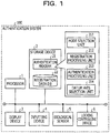
- FIG. 1 is a block diagram depicting an example of a configuration of an authentication system that uses a verification method according to a working example 1.
- An authentication system 100 depicted in FIG. 1 includes a processor 1, a storage device 2, a display device 3, an inputting device 4, a biological sensor 5, a locking controlling device 6 and so forth.
- the components mentioned are coupled for communication with each other by wire communication by a bus or the like or by wireless communication and may be accommodated in one housing, or all or some of the components may be accommodated in an independent housing.
- the processor 1 is an arithmetic operation device that implements an authentication function including a verification process according to the working example 1 by executing an authentication program 21 stored in the storage device 2.
- the processor 1 is converted into a hardware circuit that provides the authentication process including the verification process according to the working example 1 by executing the authentication program 21 read in from the storage device 2.
- a processor 1 as just described, for example, a central process unit (CPU), a micro processing unit (MPU), a digital signal processor (DSP), a field programmable gate array (FPGA) and so forth are mentioned.
- the processor 1 may be a multicore processor including two or more cores.
- the storage device 2 is a device that stores and retains the authentication program 21 that is executed by the processor 1, a registration data database (DB) 22 used by the authentication function, temporary data that is referred to or written in when the processor 1 performs a process and so forth.
- the storage device 2 is configured including both or at least one of a nonvolatile storage device and a volatile storage device. For example, a random access memory (RAM), a read only memory (ROM), a solid state drive (SSD), a hard disk drive (HDD) and so forth are mentioned.
- the display device 3 is configured so as to display a result of a process of the authentication function executed by the processor 1 and so forth.
- a liquid crystal display (LCD) for example, a liquid crystal display (LCD), an organic electroluminescence (OEL) display, an organic light emitting diode (OLED) display and so forth are mentioned.
- LCD liquid crystal display
- OEL organic electroluminescence
- OLED organic light emitting diode
- the inputting device 4 is configured to output an input signal according to an inputting operation by a user to the processor 1.
- a touch pad that may input a position by tracing a sensor in the form of a flat plate with a finger, a keyboard, a mouse, a card reader of the contact type or the contactless type, a combination of them and so forth are listed. It is to be noted that a touch panel that is a combination of the inputting device 4 and the display device 3 may be used.
- the inputting device 4 may output, for example, a signal for selecting one of a registration mode and an authentication mode as an action mode of the authentication system 100 to the processor 1. Further, the inputting device 4 may output attribute information such as a user identification (ID) of a user or the like to the processor 1 in response to an operation of the inputting device 4 by the user.
- ID user identification
- the biological sensor 5 is a sensor that acquires a biological image.
- a biological image an image of a thin film texture pattern of the pupil, an image of a blood vessel pattern on the retina, a fingerprint image, a palm vein image and so forth are listed.
- a sensor that uses a suitable one of various known principles may be used in response to the type of a biological image of the target.
- a biological sensor that acquires a vain image representative of a vein pattern of a palm includes a light emitting diode (LED) that irradiates near infrared light upon a palm, and an area sensor formed from a two-dimensional array of image pickup elements having sensitivity to near infrared light.
- CMOS complementary metal oxide semiconductor
- the locking controlling device 6 is configured such that it receives an authentication result by the authentication function implemented by the processor 1 and controls whether or not access to a protection target by the user is permitted.
- the locking controlling device 6 may be configured such that, if the authentication result by the authentication function is authentication success, the locking controlling device 6 cancels locking of a door of a room whose entry is restricted, but if the authentication result is authentication failure, the locking controlling device 6 does not cancel the locking of the door.
- the locking controlling device 6 may be configured such that it controls not physical locking of a door but permission of an electronic transaction such as a transaction in which an account at a financial institution such as a bank is used in response to an authentication result by the authentication function.
- the locking controlling device 6 is configured such that it permits, when the authentication result is authentication success, access to the account in the financial institution, but does not permit, when the authentication result is authentication failure, access to the account in the financial institution.
- the locking controlling device 6 may be configured such that it controls permission of access to a storage region, to which access is restricted, of the storage device 2 in response to the authentication result by the authentication function. It is to be noted that the locking controlling device 6 is not a presence independent of other apparatus, and for example, the function of the locking controlling device 6 may be implemented by the processor 1.
- the authentication program 21 stored in the storage device 2 is executed by the processor 1 if it is deployed for execution into a memory such as a RAM that configures the storage device 2.
- a memory such as a RAM that configures the storage device 2.
- various functioning units such as a mode selection unit 211, a registration processing unit 212, an authentication processing unit 213, and a datum axis selection unit 214 are implemented.
- the processor 1 is converted into a hardware circuit that implements the functions described above by executing the authentication program 21.
- the mode selection unit 211 is a functioning unit configured to select an action mode of the authentication system 100 from between a registration mode in which a process for registering new biological data into the registration data DB 22 is performed and an authentication mode in which a process for authenticating a biological image acquired from the biological sensor 5 is performed using registration data registered already in the registration data DB 22.
- the mode selection unit 211 is configured such that it receives an input signal according to a selection operation of an action mode by the user from the inputting device 4 and selects an action mode based on the input signal and then instructs a functioning unit according to the selected action mode to start execution of the action mode.
- the registration processing unit 212 is a functioning unit that implements a process in the registration mode.
- the registration processing unit 212 is configured such that it extracts feature points projected to an m-dimensional space from a biological image acquired from the biological sensor 5, generates new registration data using the feature points extracted from the biological image, and stores the generated registration data into the registration data DB 22.
- the registration processing unit 212 in the present working example performs, in the process for generating registration data using the feature points extracted from the biological image, selection of an optimum datum axis in the m-dimensional space by the datum axis selection unit 214 in the present working example and ordering of the feature points in a coordinate value order on the selected datum axis are performed.
- the authentication processing unit 213 is a functioning unit that implements a process in the authentication mode.
- the authentication processing unit 213 is configured such that it extracts feature points (verification data) projected to the m-dimensional space from a biological image acquired from the biological sensor 5, performs verification between the verification data and registration data registered in the registration data DB 22, and outputs success/failure of the authentication in response to a result of the verification.
- the authentication processing unit 213 in the present working example performs, in a verification process between the verification data and the registration data, selection of an optimum datum axis in the m-dimensional space by the datum axis selection unit 214 according to the present working example and verification of the feature points in a coordinate value order on the selected datum axis.
- the verification process between the verification data and the registration data by the authentication processing unit 213 is an example of a verification process of feature points.
- the datum axis selection unit 214 is configured such that it selects an optimum datum axis in the m-dimensional space according to a distribution of feature points extracted from a biological image.
- the datum axis selection unit 214 is configured such that it accepts one or more feature points (feature point group) each having a coordinate value in the m-dimensional space as an input thereto, orders the inputted feature point group in a coordinate value order on each coordinate axis of the m-dimensional space to generate m ordered feature point groups, performs neighbor discovery on a datum axis used for ordering for each of the m feature point groups to count the number of feature points (comparison time number) used as a comparison target in the neighbor discovery on the datum axis, and selects the datum axis of the feature point group that indicates the smallest comparison time number as an optimum datum axis.
- the process of neighbor discovery by the datum axis selection unit 214 is an example of a verification process of feature points.
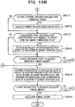
- FIG. 2 is a flow chart illustrating an example of processes in a registration mode implemented by a registration processing unit in the working example 1.
- the registration processing unit illustrated by reference to FIG. 2 may be the registration processing unit 212 depicted in FIG. 1 . It is to be noted that some of the processes illustrated in FIG. 2 are implemented by the datum axis selection unit 214 in the present working example. Execution of the processes illustrated in FIG. 2 is started taking it as a trigger that, for example, the mode selection unit 211 selects the registration mode based on an input signal from the inputting device 4.
- the processor 1 acquires a biological image obtained by image pickup of a living body part (for example, a palm, a finger or the like) of a subject (user) to be registered into the registration data DB 22 from the biological sensor 5 (S101).
- a living body part for example, a palm, a finger or the like
- the processor 1 acquires a biological image obtained by image pickup of a living body part (for example, a palm, a finger or the like) of a subject (user) to be registered into the registration data DB 22 from the biological sensor 5 (S101).
- a method for extracting one or more feature points used for authentication from a biological image a known method may be used. For example, where a palm vein image is used as the biological image, the processor 1 distinguishes a subject region in which a hand is reflected and a background region in which no hand is reflected based on the luminance value of pixels on the vein image.
- the luminance value of pixels in the subject region is higher than the luminance value of pixels in the background region. Therefore, a set of pixels having luminance values equal to or higher than a given threshold value for subject determination may be extracted as a subject region.
- the threshold value for subject determination may be set, for example, by referring to a fixed value set in advance, an average value of the luminance value of pixels in the image or the like.
- the processor 1 determines a subject region or a rectangular region included in the subject region as an extraction region and binarizes pixels in the extraction region with a threshold value for vein determination to produce a binarization image binarized to a set of pixels on which a vein may possibly be reflected and a set of the other pixels. For example, the luminance value of a pixel on which a vein is reflected is lower than the luminance value of a pixel around the first-mentioned pixel. This arises from reduced hemoglobin in the vein.
- the processor 1 may determine that pixels having luminance values lower than the threshold value for vein determination are pixels (vein pixels) on which a vein may possibly be reflected and pixels having luminance values equal to or higher than the threshold value for vein determination are pixels on which no vein is reflected.
- the threshold value for vein determination may be set, for example, by referring to an average value of the luminance value of pixels in the subject region or the like.
- the threshold value for vein determination may be determined by applying a known algorithm such as the "Otsu's binarization method" to a distribution of luminance values of pixels in the subject region. Further, the processor 1 performs a process for thinning a vein pattern, which is a set of vein pixels on a binarization image to a line having, for example, a one-pixel width using a known algorithm and extracts a position of a branch point, an end point or the like on the thinned vein pattern as a feature point.
- a known algorithm such as the "Otsu's binarization method”
- the processor 1 may refer to the width of the vein pixels on the binarization image before the thinning (for example, the thickness of the blood vessel of the vein) to acquire coordinate values including a value in the depthwise direction (for example, a distance from the biological sensor) at the extracted feature point.
- the processor 1 may store, utilizing the characteristic that, as the distance from the biological sensor increases, the thickness of a blood vessel of a vein apparently looks thinner and, as the distance decreases, the thickness apparently looks thicker, a correspondence relationship between the apparent thickness and the distance of a blood vessel into the storage device 2 in advance such that it acquires a coordinate value indicative of the depthwise value (distance) of a feature point from the width of vein pixels on a binarization image before thinning based on the correspondence relationship.
- the processor 1 may use two biological images picked up by stereo image pickup using two biological sensors to acquire a coordinate value including a depthwise value (for example, a distance from the biological sensors) at each feature point by a known technique of triangulation.
- the processor 1 refers to pixels (peripheral pixels) in a local rectangular region of a given pixel number centered at the position of an extracted feature point and sets a feature value at the feature point using a known technique such as local phase quantization (LPQ), local binary pattern (LBP), scale-invariant feature transform (SIFT)/speeded up robust features (SURF), oriented FAST and rotated binary robust independent elementary features (BRIEF) (ORB), BRIEF, binary robust invariant scalable keypoints (BRISK), D-Nets, or KAZE.
- LPQ local phase quantization
- LBP local binary pattern
- SIFT scale-invariant feature transform
- SURF speeded up robust features
- BRIEF binary robust independent elementary features
- BRISK binary robust invariant scalable keypoints
- D-Nets or KAZE.
- a normalization process of the biological image may be performed.
- Affine transformation such as expansion, reduction, rotation, or parallel translation for pixels in a subject region may be performed using the shape or the like of the entirety or part of the subject region on the biological image to perform positioning such that the subject region is positioned within a given range of the image.
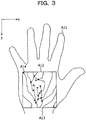
- FIG. 3 is a view (part 1) depicting an example of a biological image used for extraction of a feature point.
- a subject region A11 in which a hand is reflected is indicated by a broken line and a rectangular region A12 included in the subject region A11 is indicated by a solid line rectangle.
- a vein pattern A13 obtained by binarization, thinning and so forth is indicated by a solid line, and one or more feature points A14 extracted from the vein pattern A13 are indicated each by a white spot.
- the palm that is a portion of a hand from which the wrist and the thumb and fingers are excluded and is a portion that comes to the inner side when the hand is closed indicates a ratio of vertical and horizontal of approximately 1:1 in a state in which the hand is open. Therefore, in the example depicted in FIG. 3 , the extraction region that is a range from which biological information is extracted is set as a range including a region in which the palm is reflected or a range included in the region in which the palm is reflected, and has an aspect ratio of approximately 1:1.
- the entire hand may not be determined as a subject.
- the range indicated by the rectangular region A12 may be determined as a biological image obtained from the biological sensor 5.
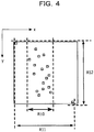
- FIG. 4 is a view illustrating a distribution of feature points extracted from the biological image exemplified in FIG. 3 .
- a distribution width indicated by a maximum value and a minimum value of the coordinate values of the feature points is substantially equal on the coordinate axes.
- the ratio (aspect ratio) between a distribution width R11 on the X axis and a distribution width R12 on the Y axis is approximately 1:1.
- the coordinate points are distributed uniformly, on the X axis, the coordinate points are distributed in a concentrated manner within a local range R10. Therefore, in the example of FIG.
- the target of neighbor discovery on the X axis may not be limited to an appropriate number within the range R10, and the number of feature points to be made a comparison target in neighbor discovery on the X axis (comparison time number) increases, which increases the arithmetic operation cost.
- the target of neighbor discovery on the Y axis may be restricted to an appropriate number in any range in the distribution width R12. Therefore, the comparison time number in neighbor discovery on the Y axis may be suppressed and the efficiency in neighbor discovery may be improved.
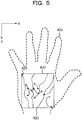
- FIG. 5 is a view (part 2) depicting another example of a biological image used for extraction of feature points.
- a subject region A21 in which a hand is reflected is indicated by a broken line and a rectangular region A22 included in the subject region A21 is indicated by a solid line rectangle similarly as in FIG. 3 .
- a vein pattern A23 obtained by binarization, thinning and so forth is indicated by a solid line, and one or more feature points A24 extracted from within the vein pattern A23 are indicated each by a white spot similarly as in FIG. 3 .
- the palm that is a portion of a hand from which the wrist and the thumb and fingers are excluded and is a portion that comes to the inner side when the hand is closed indicates a ratio of vertical and horizontal of approximately 1:1 in a state in which the hand is open. Therefore, in the example depicted in FIG. 5 , the extraction region that is a range from which biological information is extracted is set within a range including a region in which the palm is reflected or a range included in the region in which the palm is reflected, and has an aspect ratio of approximately 1:1.
- the entire hand may not be determined as a subject.
- the range indicated by the rectangular region A22 may be determined as a biological image obtained from the biological sensor 5.
- FIG. 6 is a view illustrating a distribution of feature points extracted from the biological image exemplified in FIG. 5 .
- a distribution width indicated by a maximum value and a minimum value of the coordinate values of the feature points is substantially equal on the coordinate axes similarly as in FIG. 4 .
- the ratio between a distribution width R21 on the X axis and a distribution width R22 on the Y axis is approximately 1:1.
- the feature points are distributed uniformly
- the Y axis the feature points are distributed in a concentrated manner within a local range R20. Therefore, in the example of FIG.
- the target of neighbor discovery may not be limited to an appropriate number within the range R20, and the number of feature points to be made a comparison target in neighbor discovery on the Y axis (comparison time number) increases, which increases the arithmetic operation cost.
- the target of neighbor discovery on the X axis may be restricted to an appropriate number in any range in the distribution width R21. Therefore, the comparison time number in neighbor discovery on the X axis may be suppressed and the efficiency in neighbor discovery may be improved.
- the distribution widths of feature points on the coordinate axes are substantially equal to each other, and therefore, it is difficult to select an optimum datum axis for neighbor discovery based on a distribution width.
- ratios for example, aspect ratios
- regions for example, extraction regions
- biological patterns for example, palm vein patterns
- the feature points may not be necessarily distributed uniformly on the coordinate axes, there is a problem that, even if a datum axis is selected based on the distribution widths of the feature points on the coordinate axes, the efficiency in neighbor discovery may possibly decrease.
- the datum axis selection unit 214 performs a process for performing, using a feature point group ordered in the coordinate value order using each axis of an m-dimensional space as a datum axis, simulation (simulated arithmetic operation) of neighbor discovery on the datum axes, counting the number (comparison time number) of feature points that become a comparison target in neighbor discovery on the datum axes, and selecting the datum axis of the feature point group on which the comparison time number is smaller as an optimum datum axis for neighbor discovery.
- the processes from the process S103 to the process S105 are an example of processes by the datum axis selection unit 214.
- the processor 1 generates, from the one or more feature points acquired by S102, m feature point groups (first feature point groups) ordered in the coordinate value order on the datum axes using the coordinate axes that define the m-dimensional space as the datum axes (S103). For example, in the case of feature points projected to a two-dimensional space, a first feature point group in which the feature points are ordered in the coordinate value order on the X axis and another first feature point group in which the feature points are ordered on the coordinate value order on the Y axis are generated.
- the processor 1 may treat the one or more feature points acquired from the biological image by the process S102 as a first feature point group in which they are ordered in the coordinate value order on the Y axis. In this case, by performing only a process for ordering the feature points in the coordinate value order on the X axis that is an axis different from the sub scanning direction, two first feature point groups ordered in the coordinate value order on the individual datum axes may be acquired.
- the processor 1 determines, for the first feature point group ordered in the coordinate value order on each datum axis, each of one or more feature points included in the first feature point group as a datum point and a reference point and counts the number of feature points (comparison time number) that become a comparison target in neighbor discovery on the datum axis (S104). It is to be noted that the neighbor points detected by the neighbor discovery on the datum axis may be different from the neighbor points that become an arithmetic operation target of a verification score in the verification process.
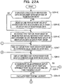
- FIG. 7 is a flow chart illustrating a counting process of a comparison time number in neighbor discovery.
- the counting process illustrated by reference to FIG. 7 may be the counting process S104 depicted in FIG. 2 .
- FIG. 7 an example of processes when attention is paid to one datum axis in the process S104 is illustrated.
- FIG. 7 processes for one first feature point group ordered using one of the X axis and the Y axis as a datum axis are exemplified.
- the processor 1 has two index values including an index value indicative of a reference position when one of a plurality of feature points included in the first feature point group is referred to as a datum point (datum point index value) and another index value indicative of a reference position when one of the plurality of feature points included in the first feature point group is referred to as a reference point.
- a datum point datum point index value
- a reference point another index value indicative of a reference position when one of the plurality of feature points included in the first feature point group is referred to as a reference point.
- to "take out a feature point” signifies to refer to one of one or more feature points ordered in the coordinate value order on a datum axis, and it is assumed that, even after a process for "taking out a feature point” is performed, this does not have an influence on the number of feature points included in the first feature point group.
- to "take out a feature point” has the same meaning as to "refer to a feature point.”
- the processor 1 takes out one feature point (datum point) in the coordinate value order (for example, in the ascending order) on the datum axis from within a first feature point group ordered in the coordinate value order on a certain datum axis (S104-1) and takes out one feature point (reference point) in the coordinate value order (for example, in the ascending order) on the datum axis (S104-2).
- the reference point index value may be set to the first number or to an index value of a reference point detected as a neighbor point first in neighbor discovery on the datum axis with respect to the datum point in the preceding operation cycle.
- the target of neighbor discovery on the datum axis with respect to the datum point in the present operation cycle may be limited using a result of neighbor discovery with respect to the datum point in the preceding operation cycle, the efficiency in neighbor discovery may be improved further.
- the datum point in the preceding operation cycle and the datum point in the current operation cycle are feature points, which neighbor with each other, ordered in the coordinate value order on the datum axis, the datum distance of a reference point that appears prior to a reference point detected as a neighbor point first in neighbor discovery on the datum axis with respect to the datum point in the preceding operation cycle (for example, a reference point whose datum distance from the datum point in the preceding operation cycle is equal to or greater than a threshold value) from the datum point in the current operation cycle is equal to or greater than the threshold value for neighbor discovery and therefore need not be used as a comparison target in the neighbor discovery.
- the datum distance has an aspect as a difference in coordinate value on the datum axis between the datum point and the reference point.
- the datum distance is indicated by a difference between the X coordinate value of the datum point and the X coordinate value of the reference point.
- the processor 1 counts up the comparison time number in neighbor discovery on the datum axis by one (S104-3). Then, the processor 1 determines whether or not the difference in coordinate value (also referred to as datum distance) on the datum axis between the datum point and the reference point is smaller than the threshold value for neighbor discovery (S104-4). If the datum distance is smaller than the threshold value for neighbor discovery (YES at S104-4), the processor 1 determines the reference point as a neighbor point with the datum point in the current operation cycle and determines whether or not the reference point is a neighbor point detected first with respect to the datum point in the current operation cycle (S104-5).
- the processor 1 determines whether or not the difference in coordinate value (also referred to as datum distance) on the datum axis between the datum point and the reference point is smaller than the threshold value for neighbor discovery (S104-4). If the datum distance is smaller than the threshold value for neighbor discovery (YES at S104-4), the processor 1 determines the reference point as a neighbor point with the datum
- the processor 1 stores (retains) an index value of the reference point with respect to the datum point in the current operation cycle (such index value is referred to also as reference point index value) as an index value of the reference point that is taken out first in neighbor discovery with respect to a datum point in the next operation cycle (S104-6).
- the processor 1 may skip the process S104-6 without executing the same.
- the processor 1 determines whether or not a next reference point to be made a discovery target is absent (S104-7). For example, if the reference point index value reaches the number of feature points included in the first feature point group, the processor 1 may determine that a next reference point to be made a discovery target is absent. If a next point to be made a discovery target is absent (YES at S104-7), the processor 1 ends the process for neighbor discovery on the datum axis with respect to the datum point in the current operation cycle. Consequently, the comparison time number for the datum point in the current operation cycle is finally determined. Then, the processor 1 determines whether or not process for neighbor discovery with respect to a next datum point may be started (S104-8).
- the processor 1 determines whether or not a next datum point to be made a discovery target is absent. For example, if the datum point index value reaches the number of feature points included in the first feature point group, the processor 1 may determine that a next datum point to be made a discovery target is absent. If a next datum point to be made a discovery target is absent (YES at S104-8), the processor 1 outputs one comparison time number as a simulation result (result of execution of the process S104) of neighbor discovery for the first feature point group on a certain one datum axis (S104-9).
- the processor 1 acquires (calculates) a total value of the comparison time number counted for the datum points on the certain one datum axis (S104-9).
- the processor 1 If it is determined in the determination of the process S104-4 that the datum distance is equal to or greater than the threshold value for neighbor discovery (NO in S104-4), the processor 1 ends the process for neighbor discovery with respect to the datum point in the current operation cycle. Consequently, the comparison time number for the datum point in the current operation cycle is finally determined. Then, the processor 1 executes the processes beginning with the process S104-8 described hereinabove. Even if the determination by the process S104-4 reveals that the reference point index value at present is a value lower than the number of feature points included in the first feature point group, the processor 1 may end the process for neighbor discovery with respect to the datum point in the current operation cycle, and the efficiency in neighbor discovery may be improved.
- the processor 1 executes the processes beginning with S104-2. Thereupon, the reference point index value is counted up, for example, by one such that a next reference point may be taken out in the coordinate value order on the datum axis from within the first feature point group.
- the processor 1 executes the processes beginning with S104-1. Thereupon, the datum point index value is counted up, for example, by one such that a next datum point may be taken out in the coordinate value order on the datum axis from within the first feature point group. Further, the reference point index value may be set to the number at the first position (for example, the first number) or may be set using a value of the reference point index value retained by the process S104-6 as described hereinabove.
- the foregoing is an example of the counting process S104 of the comparison time number in neighbor discovery illustrated in FIG. 7 .
- the flow of the processes illustrated in FIG. 7 is executed for each axis that may become a datum axis.
- the flow of the processes illustrated in FIG. 7 is executed for each of the X axis and the Y axis.
- the process S104 in which the X axis is used as the datum axis and the process S104 in which the Y axis is used as the datum axis are executed.
- FIG. 8 is a view illustrating an example of neighbor discovery with respect to a datum point where a datum axis is set to a Y axis. In the example of FIG.
- FIG. 8 six reference points P0, P1, P2, P3, P4, and P5 are depicted within a range defined by an upper limit value y1 and a lower limit value y2 for neighbor discovery including y0 that is a coordinate value on the datum axis of the datum point P0 in the current operation cycle.
- the upper limit value y1 is, for example, a coordinate value on the datum axis of a reference point detected first as a neighbor point in the neighbor discovery with respect to the datum point in the preceding operation cycle.
- the lower limit value y2 is a coordinate value obtained by adding a threshold value Rth for neighbor discovery to the coordinate value y0 on the datum axis of the datum point P0 in the current operation cycle.
- the point P0 of FIG. 8 is the reference point P0 and may become also the reference point P0.
- FIG. 9 is a view illustrating an example of neighbor discovery with respect to a datum point where a datum axis is set to the X axis in a distribution of feature points same as that of FIG. 8 .
- 13 reference points P0, P1, P2, P3, P4, P5, P6, P7, P8, P9, P10, P11, and P12 are depicted within a range defined by an upper limit value x1 and a lower limit value x2 for neighbor discovery including x0 that is a coordinate value on the datum axis of the datum point P0 in the current operation cycle.
- the upper limit value x1 is, for example, a coordinate value on the datum axis of a reference point detected first as a neighbor point by the neighbor discovery with respect to the datum point in the preceding operation cycle.
- the lower limit value x2 is a coordinate value obtained by adding the threshold value Rth for neighbor discovery to the coordinate value x0 on the datum axis of the datum point P0 in the current operation cycle.
- the point P0 in FIG. 9 is also a datum point P0 and may become also a reference point P0. It is recognized that, in comparison with the example of FIG. 8 , in the example of FIG.
- the number of comparison targets in neighbor discovery where the X axis is used as the datum axis is great and therefore the X axis is not an optimum datum axis.
- the number of comparison targets in neighbor discovery is associated with the comparison time number obtained by the process S104. For example, in the example of FIGs. 8 and 9 , the comparison time number as an execution result of the process S104 (for example, the process S104-1 to the process S104-9) where the datum axis is the X axis is greater than the comparison time number where the datum axis is the Y axis.
- process S105 After a comparison time number of neighbor discovery for all datum axes is obtained by process S104, for example, after m comparison time numbers in the m-dimensional space are obtained, the processor 1 selects a datum axis for which the comparison time number in neighbor discovery is small as an optimum datum axis (S105).
- the processor 1 stores the first feature point group ordered with the selected datum axis in association with information relating to the selected datum axis as registration data into the registration data DB 22 (S106).
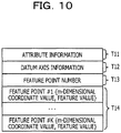
- FIG. 10 is a view illustrating an example of registration data.
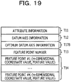
- the registration data include attribute information T11 indicative of a user ID or the like of a subject (user) from whom a biological image is provided, datum axis information T12 having information relating a datum axis selected as an optimum datum axis, a feature point number T13 indicative of the number of feature points included in a first feature point group, and a first feature point group T14 having one or more feature points ordered in the coordinate value order on the selected datum axis.
- the processor 1 generates registration data including attribute information T11 indicative of a user ID or the like of a subject (user) from whom a biological image is provided, datum axis information T12 having information relating to a selected datum axis, a feature point number T13 indicative of the number of feature points included in a first feature point group, and a first feature point group T14 having one or more feature points ordered in the coordinate value order on the selected datum axis, and stores the registration data into the registration data DB 22. It is assumed that each of the one or more feature points includes a coordinate value (m-dimensional coordinate value) in the m-dimensional space and a feature value indicative of a characteristic of a pixel around the coordinate value.
- the feature value is a value obtained from pixels around the coordinate value using a known algorithm as described hereinabove.
- the processor 1 may acquire the attribute information T11 indicative of a user ID or the like of a subject (user) from whom a biological image is provided from the inputting device 4 or the like.
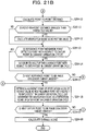
- FIG. 11 is a flow chart illustrating an example of processes in an authentication mode implemented by an authentication processing unit in the working example 1.
- the authentication processing unit illustrated by reference to FIG. 11 may be the authentication processing unit 213 depicted in FIG. 1 . It is to be noted that some of the processes illustrated in FIG. 11 are implemented by the datum axis selection unit 214 in the present working example. Execution of the processes illustrated in FIG. 11 may be started, for example, using it as a trigger that the authentication mode is selected based on an input signal from the inputting device 4 by the mode selection unit 211.
- the processor 1 acquires a biological image obtained by image pickup of a living body part (for example, a palm, a finger or the like) of a subject (user) who is to be authenticated from the biological sensor 5 (S201).
- a living body part for example, a palm, a finger or the like
- a subject (user) who is to be authenticated from the biological sensor 5 (S201).
- the processor 1 acquires one or more feature points (second feature point group) used as verification data in the authentication process from the biological image (S202).
- m natural number equal to or greater than 2
- a normalization process for the biological image may be performed in the process S202 or prior to the process S202.
- Affine transformation such as expansion, reduction, rotation, or parallel translation for pixels in a subject region may be performed using the shape of the entirety or part of the subject region on the biological image to perform positioning such that the subject region is positioned within a given range of the image.
- the processor 1 acquires registration data used in the authentication process from the registration data DB 22 (S203).
- the processor 1 may receive attribute information such as a user ID of a subject (user) to be authenticated from the inputting device 4 or the like and acquire registration data having the attribute information T11 coincident with the inputted attribute information from the registration data DB 22.
- the processor 1 performs a verification process between the verification data and the registration data to calculate a verification score indicative of a coincidence degree between the verification data and the registration data (S204).
- a verification process between the verification data and the registration data to calculate a verification score indicative of a coincidence degree between the verification data and the registration data (S204).
- the datum axis selection unit 214 performs a process for determining each of the coordinate axes that define an m-dimensional space as a datum axis, performing simulation of neighbor discovery on each datum axis using the feature point group ordered in the coordinate value order on the datum axis, counting the number of feature points (comparison time number) that are made a comparison target in the neighbor discovery on the datum axis, and selecting the datum axis of the feature point group on which the comparison time number is small as an optimum datum axis in the neighbor discovery.
- FIG. 12 is a flow chart illustrating an example of a verification process in an authentication mode.
- the verification process illustrated by reference to FIG. 12 may be the verification process S204 depicted in FIG. 11 .
- processes, for example, from a process S204-1 to a process S204-3 are an example of processes by the datum axis selection unit 214.
- the processor 1 generates, from the verification data acquired by the process S202, m feature point groups (second feature point groups) in which each of the coordinate axes that define the m-dimensional space is determined as a datum axis and which are ordered in the coordinate value order on the datum axis (S204-1). For example, in the case of feature points projected to a two-dimensional space, a second feature point group in which feature points are ordered in the coordinate value order on the X axis and another second feature point group in which feature points are ordered in the coordinate value order on the Y axis are generated.
- the processor 1 may treat the one or more feature points extracted from the biological image as a second feature point group in which they are ordered in the coordinate value order on the Y axis.
- two second feature point groups ordered in the coordinate value order on the datum axis where each of the coordinate axes that define the m-dimensional space is set as the datum axis may be acquired.
- the processor 1 determines, for the second feature point group ordered in the coordinate value order on each datum axis, each of one or more feature points included in the second feature point group as a datum point and a reference point and counts the number of feature points (comparison time number) that become a comparison target in neighbor discovery on the datum axis (S204-2). It is to be noted that a particular example of the process S204-2 is similar to the process example illustrated in FIG. 7 , and therefore, detailed description of the particular example is omitted herein.
- the processor 1 selects the datum axis on which the comparison time number of neighbor discovery is small as an optimum datum axis to the verification data (second feature point group) (S204-3).
- the processor 1 compares the datum axis of the verification data and the datum axis indicated by the datum axis information of the registration data with each other to determine whether or not the datum axis of the variation data and the datum axis of the registration data are incoincident with each other (S204-4). If the datum axis of the verification data and the datum axis of the registration data are incoincident with each other (YES in S204-4), the processor 1 orders the first feature point group of the registration data in the coordinate value order on the datum axis of the verification data (S204-5).
- the processor 1 may skip the process S204-5 without executing the same. It is to be noted that, if the subject (user) of the biological image used for generation of the registration data is a person same as the subject (user) of the biological image used for generation of the verification data, the first feature point groups of the registration data may be distributed substantially same manner as that of second feature point groups of the verification data in the m-dimensional space.
- the datum axis selection unit 214 performs simulation of neighbor discovery using the registration data (first feature point groups) and first feature point groups each ordered in the coordinate value order on an optimum datum axis are obtained, execution of the process S204-5 in the authentication process may be omitted.
- the processor 1 continues the process illustrated in FIG. 12 determining the first feature point group ordered on the datum axis of the verification data as the datum point group and determining the second feature point group ordered on the datum axis of the verification data as the reference point group (S204-6). It is to be noted that, in the following description relating to the processes of FIG. 12 , the "datum axis of verification data" is referred to as datum axis.
- To “take out a feature point” signifies to refer to one of the one or more feature points ordered in the coordinate value order on a datum axis, and it is assumed that, even after a process for "taking out a feature point” is performed, this does not have an influence on the number of feature points included in the feature point group referred to. For example, in the following description, to “take out a feature point” has the same meaning as to "refer to a feature point.” Further, it is assumed that, when the processor 1 executes the processes exemplified in FIG. 12 , the processor 1 has two index values including an index value to be used to refer to a datum point group (datum point index value) and an index value to be used to refer to a reference point of a reference point group (reference point index value).
- the processor 1 takes out a datum point from the datum point group in the coordinate value order (for example, in the ascending order) on the datum axis (S204-7) and takes out a reference point from the reference point group in the coordinate value order (for example, in the ascending order) on the datum axis (S204-8).
- the reference point index value may be set to the first number (for example, to 1), or an index value of a reference point detected as a neighbor point first in neighbor discovery on the datum axis with respect to a datum point in the preceding operation cycle may be set.
- the target of neighbor discovery on the datum axis with respect to the datum point in the current operation cycle may be restricted using a result of the neighbor discovery with respect to the datum point in the preceding operation cycle, the efficiency in neighbor discovery may be improved further.
- the datum point in the preceding operation cycle and the datum point in the current operation cycle are feature points, which neighbor with each other, ordered in the coordinate value order on the datum axis
- the datum distance of a reference point that appears prior to a reference point detected as a neighbor point first in neighbor discovery on the datum axis with respect to the datum point in the preceding operation cycle (for example, a reference point whose datum distance from the datum point in the preceding operation cycle is equal to or greater than a threshold value) from the datum point in the current operation cycle is equal to or greater than the threshold value for neighbor discovery and therefore need not be used as a comparison target in the neighbor discovery. Consequently, the efficiency in neighbor discovery may be further improved.
- the processor 1 determines whether or not the difference (datum distance) in coordinate value between the datum point and the reference point on the datum axis is smaller than the threshold value for neighbor discovery (S204-9). If the datum distance is smaller than the threshold value for neighbor discovery (YES in S204-9), the processor 1 detects the reference point as a neighbor point with respect to the datum point in the current operation cycle and calculates the point-to-point distance between the neighbor point and the datum point (S204-10). It is to be noted that, for the point-to-point distance, various distance concepts such as the Euclidean distance, Manhattan distance and so forth may be used.
- the processor 1 determines whether or not the point-to-point distance between the neighbor point and the datum point is smaller than the threshold value for neighbor discovery (S204-11), and if the point-to-point distance between the neighbor point and the datum point is smaller than the threshold value for neighbor discovery (YES in S204-11), the processor 1 calculates a verification score using the feature value of the reference point detected as the neighbor point and the feature value of the datum point (S204-12). It is to be noted that, as the verification score, a correlation value of a feature value that is a result of correlation arithmetic operation performed using the feature value, a Hamming distance between feature values represented in a bit sequence and so forth may be used.
- the processor 1 skips the process S204-12 without executing the same.
- a reference point whose point-to-point distance is equal to or greater than the threshold value for neighbor discovery is not determined as a calculation target of a verification score even if the datum distance is smaller than the threshold value.
- the present embodiment is not limited to this example, and as a modification, the process S204-10 and the process S204-11 may be omitted such that all reference points whose point-to-point distance is smaller than the threshold value for neighbor discovery are included in the calculation target of a verification score. According to the modification, since the processes (S204-10 and S204-11) relating to the point-to-point distance are omitted, the response speed in neighbor discovery may be improved as much.
- the processor 1 determines whether or not the reference point whose datum distance is determined to be smaller than the threshold value by the determination process in the process S204-9 is a neighbor point detected first with respect to the datum point in the current operation cycle (S204-13). If the reference point is a neighbor point detected first (YES in S204-13), the processor 1 stores (retains) an index value (reference point index value) of the neighbor point (reference point) with respect to the datum point in the current operation cycle as an index value to a reference point to be taken out first in neighbor discovery with respect to the datum point in the next operation cycle (S204-14). On the other hand, if the reference point is a neighbor point detected for the second or later time with respect to the datum point in the current operation cycle (NO in S204-13), the processor 1 may skip the process S204-14 without executing the same.
- the processor 1 determines whether or not a next reference point to be made a discovery target is absent (S204-15). For example, if the reference point index value reaches the number of feature points (reference points) included in the reference point group, the processor 1 may determine that a next reference point to be made a discovery target is absent.
- the processor 1 ends the processes for neighbor discovery on the datum axis with respect to the datum point in the current operation cycle, and determines a reference point of a verification score of the highest value as a most neighbor point with respect to the datum point in the current operation cycle (the most neighbor point is sometimes referred to as corresponding point to the datum point) and determines the verification score as a verification score to the datum point in the current operation cycle (S204-16).
- the processor 1 executes the processes beginning with S204-8. Thereupon, the reference point index value is counted up, for example, by one such that a next reference point may be taken out in the coordinate value order on the datum axis from the reference point group.
- the processor 1 determines whether or not the process for neighbor discovery with respect to a next datum point is to be continued (S204-17). For example, in the process S204-17, the processor 1 determines whether or not a next datum point to be made a discovery target is absent. For example, if the datum point index value reaches the number of feature points (datum points) included in the datum point group, the processor 1 may determine that a next datum point to be made a discovery target is absent. If a next datum point to be made a discovery target is absent (YES in S204-17), the processor 1 calculates an overall score using one or more verification scores acquired by execution of the process S204-16 for each of the one or more datum points (S204-18).
- the processor 1 may determine, as the overall score, a value obtained, for example, by ordering one or more verification scores in the descending order of the score value, selecting a given number of verification scores from the top (for example, 10 top verification scores), and performing various statistical processes using the selected given number of verification scores. For example, the processor 1 may determine an average value or a median of the selected given number of verification scores as the overall score.
- the processor 1 executes the processes beginning with S204-7. Thereupon, the datum point index value is counted up, for example, by one such that a next datum point may be taken out in the coordinate value order on the datum axis from the datum point group. Further, the reference point index value may be set to the top number (for example, to the first) or may be set using a value of the reference point index value retained by the process S204-14.
- the processor 1 ends the process for neighbor discovery with respect to the datum point in the current operation cycle and executes the processes beginning with the process S204-16 described hereinabove. Consequently, even if the reference point index value at present is a value lower than the number of feature points (reference points) included in the reference point group, the process for neighbor discovery with respect to the datum point in the current datum point may be ended, and the efficiency in neighbor discovery may be improved further.
- the processor 1 compares the overall score acquired by the process S204 with the threshold value for authentication to determine a degree of coincidence between the verification data and the registration data (S205). If the overall score is equal to or higher than the threshold value for authentication (YES in S205), the processor 1 determines that the verification data and the registration data coincide with each other and outputs an authentication result indicative of success in authentication (S206). For example, the processor 1 may output the authentication result indicative of success in authentication to the display device 3. For example, the processor 1 may output the authentication result indicative of success in authentication to the locking controlling device 6.
- the processor 1 determines that the verification data and the registration data do not coincide with each other and outputs an authentication result indicative of failure in authentication (S207). For example, the processor 1 may output the authentication result indicative of failure in authentication to the display device 3. For example, the processor 1 may output the authentication result indicative of failure in authentication to the locking controlling device 6.
- the foregoing is an example of the processes in the authentication mode implemented by the authentication processing unit 213 in the working example 1.
- the description of the processes illustrated in FIGs. 11 and 12 is given focusing on an authentication process (verification process) between one verification data and one registration data.
- the working example 1 is limited to this but may be applied, for example, also to "1:N authentication" in which an authentication process (verification process) between one verification data and a plurality of registration data is performed.
- the processor 1 may acquire, for example, totaling N registration data from the registration data DB 22 in the process S203 illustrated in FIG. 11 .
- the processor 1 may acquire N registration data by single time execution of the process S203.
- the processor 1 may loop the processes beginning with the process S203 for one registration data to acquire totaling N registration data.
- the process S203 for acquiring registration data from the registration data DB 22 may not be executed between the process S202 and the process S204 illustrated in FIG. 11 but may be executed between the process 5204-3 and the process S204-4 illustrated in FIG. 12 .
- the series process of the processes S204-4 to S204-18 and the processes S205 to S207 may be executed to implement 1:N authentication.
- an authentication process between all of the N registration data and the verification data may be performed, or at the point of time at which an authentication result of success in authentication is obtained, the authentication process (verification process) of the loop by N times may be ended without acquiring succeeding registration data from the registration data DB 22 and then an authentication result of success in authentication may be conveyed to the locking controlling device 6.
- the authentication process may not be conveyed to the locking controlling device 6.
- N authentication results obtained by an authentication process executed by N times using N registration data all result in failure in authentication
- a single authentication result indicative of failure in authentication may be conveyed to the locking controlling device 6.
- the processor 1 may convey one authentication result indicative of success in authentication to the locking controlling device 6.
- the response speed of feature point verification may be increased while the verification accuracy of feature points is maintained.
- the authentication system 100 to which such a verification process of feature points is applied may improve the response speed of an authentication process while degradation of the authentication accuracy is suppressed.
- the authentication system 100 is an example of a system to which the verification process according to the working example 1 is applied.
- a character recognition system, an object detection system and so forth may be listed.
- a working example 2 is described.
- an authentication system 100 according to the working example 2 a technique for improving the response speed of an authentication process where an optimum datum axis is different between registration data and verification data is introduced.
- the working example 2 is different from the working example 1 in that a result of ordering in the coordinate value order using each of coordinate axes that define an m-dimensional space as a datum axis is retained in registration data stored in the registration data DB 22. Consequently, in the working example 2, the response speed of an authentication process where a subject (user) of verification data and a subject (user) of registration data are different from each other is improved.
- first feature point groups of the registration data may not be re-ordered into those in the coordinate value order on the datum axes of the verification data. Therefore, the process S204-5 that is executed when the datum axis of verification data and the datum axis of registration data are incoincident with each other in the verification process according to the working example 1 illustrated in FIG. 12 may be omitted. Consequently, while the verification accuracy of feature points is maintained, the response speed in feature point verification may be increased.
- the authentication system 100 to which such a verification process of feature points as just described is applied may improve the response speed of an authentication process while degradation of the authentication accuracy is suppressed.
- FIG. 13 is a flow chart illustrating an example of processes in a registration mode implemented by a registration processing unit in the working example 2.
- the registration processing unit illustrated by reference to FIG. 13 may be the registration processing unit 212 depicted in FIG. 1 .
- Some of the processes illustrated in FIG. 13 are implemented by the datum axis selection unit 214 similarly as in the working example 1.
- the process S103 to the process S105 correspond to the processes by the datum axis selection unit 214.
- Execution of the processes illustrated in FIG. 13 may be started taking it as a trigger that the registration mode is selected based on an input signal from the inputting device 4 by the mode selection unit 211.
- the process S101 to the process S105 from among the processes illustrated in FIG. 13 may have similar process contents to those in the working example 1, and therefore, description of them is omitted herein.
- the processor 1 After a datum axis (datum axis for registration data) optimum to the registration data is selected by the datum axis selection unit 214, the processor 1 compares a first feature point group ordered on the selected datum axis and another first feature point group ordered on an axis different from the selected datum axis to generate an index conversion pair table having index conversion pairs paring index values of corresponding feature points (S107A). For example, the processor 1 generates, in the process S107A, an index conversion pair for converting an ordering result of the first feature point group ordered on the coordinate axis different from the datum axis for registration data and an ordering result of the first feature point group ordered on the datum axis for registration data.
- the processor 1 may determine feature points of the same coordinate value as corresponding feature points. Where a plurality of feature points whose coordinate values are same as each other exist, the corresponding feature points may be restricted using a condition that the feature values are same in addition to the condition that the coordinate values are same.
- the processor 1 generates registration data including attribute information indicative of a user ID or the like of the subject (user) from whom the biological image for registration data is provided, the first feature point group ordered on the datum axis for registration data, the feature point number representative of the number of feature points included in the first feature point group, the information relating to the datum axis for registration data (datum axis information), and the index conversion pair table, and stores the generated registration data into the registration data DB 22 (S106A).
- the index conversion pair table T15A has the number of index conversion pairs (index conversion pair #1 to index conversion pair #K) substantially equal to the number indicated by the feature point number T13.
- the index conversion pairs are ordered in the index value order table of the first feature point group ordered on an axis different from the datum axis for registration data in the index conversion pair table.
- index values of the first feature point group ordered on an axis different from the datum axis for registration data are represented (retained) in an order of the index conversion pairs in the index conversion pair table.
- each index conversion pair has an index value (after-conversion index) at which a corresponding feature point is positioned in the first feature point group ordered on the datum axis for registration data.
- the processor 1 when the processor 1 generates a conversion pair of an index value of a feature point stored first in the first feature point group ordered on the axis different from the datum axis for registration data and an index value of a corresponding feature point in the first feature point group ordered on the datum axis for registration data, the processor 1 may store the index value (after-conversion index) of the corresponding feature point in the first feature point group ordered on the datum axis for registration data as an index conversion pair into the first position in the index conversion pair table.
- a feature point has a coordinate value in a three-dimensional space
- there are three ordering results where each of the coordinate axes that define the three-dimensional space is used as a datum axis.
- One of the ordering results is retained as a first feature point group T14 ordered on a selected datum axis into registration data.
- the two remaining ordering results are retained as index conversion pair tables T15A and T16A into the registration data.
- registration data in the working example 2 may retain, for a feature point projected to the m-dimensional space, one first feature point group and m-1 index conversion pair tables.
- an order may be determined for the coordinate axes of the m-dimensional space in advance such that an order in which the index conversion pair tables are stored into the registration table is determined in accordance with the determined order. For example, in the case of a three-dimensional space, an order may be determined such that the X axis is the first, the Y axis is the second, and the Z axis is the third, and when an index conversion pair table is stored for the Y axis and the Z axis, the index conversion pair tables may be stored such that the index conversion pair table for the Y axis is stored first and the index conversion pair table for the Z axis is stored second.
- the index conversion pair tables may be stored such that the index conversion pair table for the X axis is stored first and the index conversion pair table for the Z axis is stored second. Further, where an index conversion pair table is stored for the X axis and the Y axis, the index conversion pair tables may be stored such that the index conversion pair table for the X axis is stored first and the index conversion pair table for the Y axis is stored second. Also in a verification process of a feature point in the authentication mode, if a rule same as this rule is applied, a corresponding index conversion pair table may be selected.
- FIG. 16 is a flow chart illustrating an example of a verification process of a feature point in an authentication mode implemented by an authentication processing unit in the working example 2.
- the authentication processing unit illustrated by reference to FIG. 16 may be the authentication processing unit 213 depicted in FIG. 1 .
- the verification process illustrated in FIG. 16 is different from the verification process in the working example 1 illustrated in FIG. 12 in that, for example, the process 204-5 is rewritten into a process S204-19A and the process S204-6 is rewritten into a process S204-20A.
- the process S203 for acquiring registration data from the registration data DB 22 may be executed between the process S204-3 and the process S204-4.
- 1:N authentication may be implemented by executing, every time one registration data is acquired from the registration data DB 22 by the process S203, a series of processes of the processes S204-4 to S204-18, processes S204-19A and S204-20A, and processes S205 to S207.
- the processor 1 determines that the selected datum axis and the datum axis of the registration data are incoincident with each other in the process S204-4 (YES in S204-4), the processor 1 selects an index conversion pair table corresponding to the selected datum axis from among the index conversion pair tables stored in the registration data (S204-19A).
- the selection method of a corresponding index conversion pair table may be such as described in the description of the registration process in the working example 2.
- the processor 1 may skip the process S204-19A omitting execution of the same.
- the processor 1 determines the first feature point group ordered on an axis same as the datum axis of the verification data as a datum point group and determines the second feature point group ordered on the datum axis of the verification data as a reference point group and then continues the succeeding processes (S204-20A). For example, if the selected datum axis and the datum axis of the registration data are incoincident with each other, the processor 1 may use, as the first feature point group ordered on the axis same as the datum axis of the verification data, the first feature point group that mediates a conversion pair (index conversion pair table) ordered on the datum axis of the verification data.
- the processor 1 may use, as the first feature point group ordered on the axis same as the datum axis of the verification data, the first feature point group T14 set in the registration data.
- the processor 1 may use, as the conversion pair ordered on the datum axis of the verification data, the index conversion pair table selected by the process S204-19A.
- the processor 1 when the processor 1 takes out the datum point in the coordinate value order on the datum axis selected at the process S204-3 from within the datum point group, the processor 1 may take out, after converting the datum point index value into an after-conversion index using the selected index conversion pair table, feature points (datum points) using the after-conversion index. Consequently, even where the datum axis of the verification data and the datum axis of the registration data are different from each other, the first feature point group of the registration data may not be re-ordered on the datum axis of the verification data.
- the datum axis of the verification data and the datum axis of the registration data are different from each other, even if the first feature point group of the registration data is not re-ordered on the datum axis of the verification data, increase of the arithmetic operation cost in the verification process of feature points may be suppressed and the response speed of the feature point verification may be increased while the verification accuracy of feature points is maintained.
- the authentication system 100 to which such a verification process as just described is applied may improve the response speed of an authentication process while degradation of the authentication accuracy is suppressed.
- the authentication system 100 to which such a verification process as just described is applied may suppress increase of the arithmetic operation cost in an authentication process while degradation of the authentication accuracy is suppressed, and may significantly improve the response speed of an authentication process in 1:N authentication.
- the authentication system 100 described above is an example of a system to which the verification process according to the working example 2 is applied.
- a character recognition system, an object detection system and so forth may be listed.
- a working example 3 is described.
- an alternative proposal of a technique for improving the response speed of an authentication process where an optimum datum axis is different between registration data and verification data is introduced.
- the working example 3 is different from the working example 1 and the working example 2 in that a concept of a system datum axis shared by all registration data stored in the registration data DB 22 of the authentication system 100 is newly added.
- information relating to a datum axis and a feature point number are collected from one or more registration data stored in the registration data DB 22, and the feature point number is totaled for each of the datum axes indicated by the collected information.
- a datum axis having a sufficiently high ratio to the total number of the collected feature point numbers may be selected as a system datum axis.
- the processor 1 in the working example 3 is configured such that it selects, as a system datum axis, a datum axis that has, from among feature point numbers for individual datum axes, a feature point number that indicates a maximum ratio to the total number when feature point numbers for individual datum axes are totaled and that has feature point numbers whose ratio is equal to or higher than a given value.
- a process for re-ordering each first feature point group of registration data ordered on a datum axis different from the selected datum axis in the coordinate value order on the system datum axis may be executed, for example, at a timing different from the timing at which an authentication process is executed. From those, in the working example 3, it is possible to raise the probability that the datum axes of verification data and registration data may coincide with each other and to raise the response speed in feature point verification while the verification accuracy of feature points is maintained.
- the authentication system 100 to which such a verification process as described above is applied may improve the response speed of an authentication process while degradation of the authentication accuracy is suppressed.
- FIG. 17 is a block diagram depicting an example of a configuration of an authentication system according to the working example 3.
- the configuration example of the authentication system 100 is different from the configuration example of the working example 1 depicted in FIG. 1 in that a system datum axis selection unit 215B is added to the authentication program 21 stored in the storage device 2.
- the configuration example of the authentication system 100 is different from the configuration example of the working example 1 depicted in FIG. 1 in that the storage device 2 stores system datum axis information 23B. Since the configuration of the other part may be similar to the configuration of the working example 1 or the working example 2, description of the configuration is omitted herein. In the following, processes implemented by the system datum axis selection unit 215B are described.
- FIG. 18 is a flow chart illustrating an example of processes implemented by a system datum axis selection unit in the working example 3.
- the system datum axis selection unit illustrated by reference to FIG. 18 may be the system datum axis selection unit 215B depicted in FIG. 17 .
- Execution of the processes illustrated in FIG. 18 is started at an arbitrary timing different from a timing at which an authentication process is executed.
- the processor 1 may start execution of the processes illustrated in FIG. 18 taking it as a trigger that new registration data is stored into the registration data DB 22 by a registration process.
- the processor 1 may start execution of the processes illustrated in FIG. 18 taking lapse of time as a trigger.
- the processor 1 may start execution of the process illustrated in FIG.
- the processor 1 may start execution of the processes illustrated in FIG. 18 taking it as a trigger that an arbitrary calendar schedule such as the third Sunday of every month comes.
- the processor 1 may start execution of the processes illustrated in FIG. 18 at an arbitrary timing within a time zone within which the authentication system 100 is not operated by the user.
- the example of the registration data is different from the example of the registration data in the working example 1 illustrated in FIG. 10 in that optimum datum axis information T17B is added.
- the processor 1 may store registration data that includes the optimum datum axis information T17B provided additionally as depicted in FIG. 19 into the registration data DB 22.
- optimum datum axis information T17B information relating to an optimum datum axis selected by a process (for example, S105) of the datum axis selection unit 214 is set.
- datum axis information T12 information relating to a datum axis used in ordering of feature points of the first feature point group T14 is set. For example, where the first feature point group T14 is ordered in the coordinate value order on the X axis, information indicating that the X axis is a datum axis is set to the datum axis information T12. It is to be noted that a particular example of the registration process in the working example 3 is hereinafter described.
- the processor 1 totals the feature point number T13 of each of one or more registration data acquired from the registration data DB 22 in response to the datum axis indicated by the optimum datum axis information T17B (S302). For example, where each of the one or more registration data acquired from the registration data DB 22 has feature points projected to the two-dimensional space defined by the X axis and the Y axis, the processor 1 totals the feature point number T13 of the registration data whose optimum datum axis information T17B indicates the X axis and totals the feature point number T13 of the registration data whose optimum datum axis information T17B indicates the Y axis.
- the processor 1 determines the total of the total values of the datum axes as a whole number and calculates a ratio of the totaled value for each datum axis to the whole number (S303) and selects a datum axis with regard to which the calculated ratio is equal to or higher than a threshold value for system datum axis selection as a system datum axis (S304).
- the threshold value for system datum axis selection is a value that may be adjusted suitably in response to an operation situation of the authentication system 100, and some value (real number), for example, within a range from 0.8 to 1.0 may be used as a sufficiently high ratio.
- the processor 1 may calculate the ratio for one of the datum axes and determines whether or not the ratio calculated for the one datum axis is equal to or higher than the threshold value for system datum axis selection described above.
- the processor 1 may compare a second threshold value for system datum axis selection which indicates a sufficiently low ratio (for example, some value (real number) within a range from 0.0 to 0.2) and the calculated ratio with each other and select, if the calculated ratio is equal to or lower than the second threshold value, another datum axis with regard to which the ratio is not calculated as a system datum axis.
- the processor 1 may calculate a ratio of the feature point number on a datum axis different from the system datum axis indicated by the system datum axis information 23B stored in the storage device 2.
- the processor 1 compares the calculated ratio and the threshold value for system datum axis selection described above with each other and selects a datum axis with regard to which the calculated ratio is equal to or higher than the threshold value for system datum axis selection as a system datum axis.
- a system datum axis indicated by the system datum axis information 23B may be maintained until the ratio of a feature point number on a different datum axis becomes a sufficiently high ratio.
- the processor 1 refers to the system datum axis information 23B from the storage device 2 to determine whether or not the system datum axis indicated by the system datum axis information 23B and the system datum axis selected by the process S304 are incoincident with each other (S305). If it is determined that the system datum axis indicated by the system datum axis information 23B and the selected system datum axis are incoincident with each other (YES in S305), the processor 1 updates the system datum axis information 23B in the storage device 2 using the information relating to the system datum axis selected by the process S304 (S306).
- the processor 1 may skip the process S306 to the process S310 without executing them and end the process illustrated in FIG. 18 .
- the processor 1 extracts, from the registration data stored in the registration data DB 22, registration data whose datum axis indicated by the datum axis information T12 does not coincide with the system datum axis selected by the process S304 (S307). Then, the processor 1 re-orders the first feature point group T14 of the extracted registration data in the coordinate value order on the system datum axis (S308). Consequently, the first feature point group T14 of the registration data becomes a feature point group that has one or more feature points ordered in the coordinate value order on the system datum axis.
- the processor 1 updates the datum axis information of the extracted registration data using the information relating to the system datum axis selected by the process S304 (S309). Then, the processor 1 updates the registration data in the registration data DB 22 using the registration data having the values after updated (S310).
- the first feature point group T14 of the registration data stored in the registration data DB 22 is placed into a state in which it is ordered in the coordinate value order on the system datum axis selected by the process S304. Consequently, in one aspect of the authentication system 100 according to the working example 3, the probability that the datum axis of registration data may coincide with the datum axis of verification data in an authentication process may be raised.
- the ratio of datum axes of the inputted verification data may be considered substantially equal to the ratio of the datum axes of the registration data registered in the authentication system 100. Therefore, by ordering the feature points of the registration data using the system datum axis selected in response to a ratio obtained by totaling of the registered registration data, the probability that the datum axis of the verification data inputted upon authentication and the datum axis of the registration data may coincide with each other may be increased. Consequently, while the verification accuracy of feature points is maintained, the response speed in feature point verification may be increased.
- the authentication system 100 to which such a verification process as just described is applied may improve the response speed of an authentication process while degradation of the authentication accuracy is suppressed.
- FIG. 20 is a flow chart illustrating an example of the registration process implemented by the registration processing unit 212 in the working example 3.
- Some of the processes illustrated in FIG. 20 are implemented by the datum axis selection unit 214 similarly as in the working example 1.
- the process S103 to the process S105 correspond to processes by the datum axis selection unit 214.
- Execution of the processes illustrated in FIG. 20 may be started taking it as a trigger that, for example, the mode selection unit 211 selects the registration mode based on an input signal from the inputting device 4.
- the process S102 to the process S105 from among the processes illustrated in FIG. 20 may have similar process contents to those in the working example 1 illustrated in FIG. 2 , and therefore, description of them is omitted herein.
- the processor 1 After a datum axis optimum to registration data (datum axis for registration data) is selected by the datum axis selection unit 214, the processor 1 refers to the system datum axis information 23B stored in the storage device 2 to determine whether or not an invalid value is set to the system datum axis information 23B (S108B). For example, if a null value is set to the system datum axis information 23B, the processor 1 may determine that an invalid value is set. For example, if the null value is not set to the system datum axis information 23B, the processor 1 may determine that an invalid value is not set to the system datum axis information 23B.
- the processor 1 may determine that an invalid value is set to the system datum axis information 23B. For example, when the value of the system datum axis information 23B is set to a value indicative of one of the m datum axes that define the m-dimensional space, the processor 1 may determine that an invalid value is not set to the system datum axis information 23B.
- the processor 1 If it is determined by the process S108B that an invalid value is set to the system datum axis information 23B (YES in S108B), the processor 1 generates registration data including attribute information T11 indicative of a user ID or the like of a subject (user) from whom a biological image for registration data is provided, a first feature point group T14 ordered on the datum axis for registration data, datum axis information T12 set using information relating a datum axis for registration data, optimum datum axis information T17B set using the information relating to the datum axis for registration data, and a feature point number T13 indicative of the number of one or more feature points included in a first feature point group, and stores the generated registration data into the registration data DB 22 (S106B), thereby ending the process illustrated in FIG.
- attribute information T11 indicative of a user ID or the like of a subject (user) from whom a biological image for registration data is provided
- a first feature point group T14 ordered on the datum axi
- a first feature point group ordered using the datum axis for registration data is set to the system datum axis information 23B
- a first feature point group ordered using the datum axis for registration data is set to the registration data to suppress increase of the arithmetic operation cost for a verification process of feature points between verification data of the same subject (user) and registration data.
- the processor 1 determines whether an invalid value is not set to the system datum axis information 23B (NO in S108B). If it is determined by the process S108B that an invalid value is not set to the system datum axis information 23B (NO in S108B), the processor 1 generates registration data including attribute information T11 indicative of a user ID or the like of a subject (user) from whom a biological image for registration data is provided, a first feature point group T14 ordered on the datum axis same as the system datum axis information 23B, a feature point number T13 indicative of the number of one or more feature points included in the first feature point group, datum axis information T12 set using information indicative of an ordering direction of the first feature point group T14 (same datum axis as the system datum axis information 23B), and optimum datum axis information T17B set using information relating to the datum axis for registration data (datum axis selected by the process S105), and stores the generated registration data into the registration
- FIG. 21 is a flow chart illustrating an example of a verification process of feature points in an authentication mode implemented by an authentication processing unit according to a modification to the working example 3.
- the authentication processing unit illustrated by reference to FIG. 21 may be the authentication processing unit 213 depicted in FIG. 17 .
- the example of the processes illustrated in FIG. 21 may be executed when a valid value is set to the system datum axis information 23B.
- the processor 1 does not execute the process S204-1 to the process S204-3 for selecting an optimum datum axis for a second feature point group of verification data but selects a system datum axis indicated by the system datum axis information 23B as a datum axis of the verification data (S204-3B). Then, the processor 1 orders the second feature point group of the verification data in the coordinate value order on the system datum axis (S204-21B).
- the processor 1 may treat the one or more feature points (verification data) acquired from the biological image by the process S202 as a second feature point group in which the feature points are ordered in the coordinate value order on the Y axis. In this case, when the system datum axis coincides with the sub scanning direction, the processor 1 may skip the process S204-21B without executing the same.
- the processor 1 compares the datum axis of the verification data (for example, the system datum axis) and a datum axis indicated by datum axis information of the registration data (datum axis of the registration data) to determine whether or not the datum axis of the verification data and the datum axis of the registration data are incoincident with each other (S204-4). If the datum axis of the verification data and the datum axis of the registration data are incoincident with each other (YES in S204-4), the processor 1 orders the first feature point group of the registration data in the coordinate value order on the datum axis of the verification data (S204-5).
- the processor 1 updates the registration data DB 22 using the registration data ordered in the coordinate value order on the datum axis of the verification data (for example, on the system datum axis) (S204-22B). It is assumed that, thereupon, the datum axis information of the registration data after ordered is set to a value indicating the system datum axis.
- the registration data is referred to in the next or succeeding operation cycle by the process S204-22B, the system datum axis and the datum axis of the registration data coincide with each other, and the process S204-5 may not be executed.
- process contents similar to the process contents in the process example of the working example 1 illustrated in FIG. 12 may be performed, description of them is omitted herein.
- the process for acquiring registration data from the registration data DB 22 (S203 of FIG. 11 ) may not be executed between the process S202 and the process S204 illustrated in FIG. 11 but may be executed between the process S204-3B and the process S204-4 or between the process S204-21B and the process S204-4 illustrated in FIG. 21 .
- a series process of the processes S204-4 to S204-18 and the processes S205 to S207 may be executed to implement 1:N authentication.
- the process S305 to the process S310 from among the processes of the system datum axis selection unit 215B may be omitted.
- the registration data are ordered in the coordinate value order on the system datum axis (S204-5) and the registration data DB 22 is updated using the registration data after ordered (S204-22B). Consequently, since the registration data may not reordered using the system datum axis, the arithmetic operation load by the process of the system datum axis selection unit may be reduced as much.
- the ratio of the datum axes of the inputted verification data may be considered to be substantially equal to the ratio of the datum axes of the registration data registered in the authentication system 100
- the probability that the ordering directions of the registration data stored in the registration data DB and the verification data may coincide with each other may be increased, and the response speed in feature point verification may be increased further while the verification accuracy of feature points is maintained.
- the authentication system 100 to which such a verification process as just described is applied may further improve the response speed of an authentication process while degradation of the authentication accuracy is suppressed. It is to be noted that the authentication system 100 described above is an example of a system to which the verification process according to the modification to the working example 3 is applied.
- a character recognition system As another example of the system to which the verification process according to the modification to the working example 3 is applied, a character recognition system, an object detection system and so forth may be listed.
- the verification process according to the modification to the working example 3 By applying the verification process according to the modification to the working example 3 to such application systems, for example, it is possible to increase the response speed in character recognition while the recognition accuracy is maintained or to raise the response speed in object detection while the detection accuracy is maintained.
- the working example 4 is different from the working example 1 in that an authentication process is performed using a first feature point group of registration data as a reference point group and using a second feature point group of verification data as a datum point group. Consequently, in the working example 4, a process for selecting an optimum datum axis for a second feature point group of verification data may not be executed. This is because, in the working example 4, a second feature point group of verification data (for example, a datum point group) may be ordered in the coordinate value order on a datum axis of a first feature point group of registration data (for example, a reference point group).
- execution of the process S204-1 to the process S204-3 in the verification process in the working example 1 illustrated in FIG. 12 may be omitted. Consequently, the response speed of feature point verification may be increased while the verification accuracy of feature points is maintained.
- the authentication system 100 to which such a verification process as just described is applied may improve the response speed of an authentication process while degradation of the authentication accuracy is suppressed.
- FIG. 22 is a flow chart illustrating an example of a verification process of feature points in an authentication mode implemented by an authentication processing unit in the working example 4.
- the authentication processing unit illustrated by reference to FIG. 22 may be the authentication processing unit 213 depicted in FIG. 1 .
- the process S204-1 to the process S204-3 are omitted in comparison with the process example of the working example 1 illustrated in FIG. 12 . This is because, in the authentication process (verification process) in the working example 4, the process for selecting an optimum datum axis for a second feature point group of verification data may not be executed.
- the processor 1 determines whether or not the ordering direction of verification data is incoincident with the datum axis of registration data (S204-4C). For example, where, as a scanning direction of pixels when feature points are extracted from a biological image for verification, the X axis is determined as a main scanning direction and the Y axis is determined as a sub scanning direction, one or more feature points extracted from a biological image are placed into a state in which they are ordered in the coordinate value order on the Y axis that is the sub scanning direction.
- the processor 1 compares the sub scanning direction in scanning of pixels when feature points are extracted from the biological image for verification and the datum axis information T12 of the registration data with each other, and when the datum axis indicated by the datum axis information T12 of the registration data does not coincide with the sub scanning direction, the processor 1 may determine that the ordering direction of the verification data and the datum axis of the registration data are incoincident with each other.
- the processor 1 orders the second feature point group of the verification data using the datum axis indicated by the datum axis information T12 of the registration data (S204-5C). On the other hand, if it is determined by the process S204-4C that the ordering direction of the verification data is coincident with the datum axis of the registration data (NO in S204-4C), the processor 1 may skip the process S204-5C omitting execution of the same.
- the processor 1 continues the processes illustrated in FIG. 22 determining the first feature point group of the registration data as a reference point group and determining the second feature point group of the verification data as a datum point group (S204-6C).
- the "datum axis" in and after a process S204-7 signifies an axis same as the datum axis of the registration data (first feature point group). Since, in the working example 4, the processes beginning with the process S204-7 are similar to the processes in the process example of the working example 1 illustrated in FIG. 12 , description of them is omitted herein. Further, in the working example 4, since a flow of the overall authentication process may be same as the flow in the process example of the working example 1 illustrated in FIG. 11 , description of the flow is omitted herein.
- the processor 1 may acquire, for example, totaling N registration data from the registration data DB 22 by the process S203 illustrated in FIG. 11 .
- the processor 1 may acquire N registration data by single time execution of the process S203.
- the processor 1 may loop the processes beginning with the process S203 for one registration data to acquire totaling N registration data.
- the process S203 by N times for acquiring registration data from the registration data DB 22 may not be executed between the process S202 and the process S204 illustrated in FIG. 11 but may be executed immediately before the process S204-4C illustrated in FIG. 22 .
- the authentication result may not be conveyed to the locking controlling device 6.
- the processor 1 may convey one authentication result indicative of success in authentication to the locking controlling device 6.
- the datum axis selection process for the second feature point group of the verification data may not be executed, and the response speed in feature point verification may be increased as much and also the verification accuracy of feature points is maintained.
- the authentication system 100 to which such a verification process as just described is applied may suppress degradation of the authentication accuracy and may increase the response speed of an authentication process. It is to be noted that the authentication system 100 described above is an example of a system to which the verification process according to the working example 4 is applied.
- a character recognition system As another example of a system to which the verification process according to the working example 4 is applied, also a character recognition system, an object detection system and so forth may be listed.
- a character recognition system As another example of a system to which the verification process according to the working example 4 is applied, also a character recognition system, an object detection system and so forth may be listed.
- the process for ordering a second feature point group of verification data in the coordinate value order on a datum axis of registration data may be omitted.
- the process S204-5C may be omitted.
- the authentication processing unit 213 in the present modification may be configured such that it executes, in the process example illustrated in FIG.
- the process (S204-14) for retaining an index value of a neighbor point (reference point) detected first with respect to a datum point in the current operation cycle when the ordering direction of verification data and the datum axis of registration data coincide with each other does not execute the process when the ordering direction of the verification data and the datum axis of the registration data do not coincide with each other.
- neighbor discovery for a reference point with respect to a datum point may be started, for example, beginning with a reference point positioned first in the reference point group without reflecting a result of neighbor discovery of a datum point in the preceding operation cycle.
- reference points later in the coordinate value order on the datum axis may not be determined as a target for neighbor discovery, and therefore, the number of comparison targets for neighbor discovery may be reduced in comparison with that in an alternative case in which neighbor discovery is performed on a round-robin basis between the datum points and the reference points. Therefore, the response speed in feature point verification may be increased while the verification accuracy of feature points is maintained.
- the authentication system 100 to which such a verification process as just described is applied may suppress increase of the arithmetic operation cost in an authentication process while degradation of the authentication accuracy is suppressed, and may significantly improve the response speed of an authentication process in 1:N authentication.
- the authentication system 100 described above is an example of a system to which the verification process according to the modification 1 to the working example 4 is applied.
- a character recognition system As another example of a system to which the verification process according to modification 1 to the working example 4 is applied, also a character recognition system, an object detection system and so forth may be listed.
- an execution result of the process for ordering a second feature point group of verification data in the coordinate value order on a datum axis of registration data may be retained (stored) in the storage device 2 until after the authentication process for all of the verification data is completed.
- 1:N authentication in which verification of one verification data with a plurality of registration data is performed, by retaining an execution result of the process S204-5C, and, upon execution of the process S204-5C for the second time, by utilizing the execution result (ordering result) retained in the storage device 2, the arithmetic operation cost for ordering a second feature point group may be reduced. Therefore, the response speed in feature point verification may be increased while the verification accuracy of feature points is maintained.
- the authentication system 100 to which such a verification process as just described is applied may suppress increase of the arithmetic operation cost in an authentication process while degradation of the authentication accuracy is suppressed, and may significantly improve the response speed of an authentication process in 1:N authentication.
- the authentication system 100 described above is an example of a system to which the verification process according to the modification 2 to the working example 4 is applied.
- a character recognition system As another example of a system to which the verification process according to modification 2 to the working example 4 is applied, also a character recognition system, an object detection system and so forth may be listed.
Landscapes
- Engineering & Computer Science (AREA)
- Theoretical Computer Science (AREA)
- General Physics & Mathematics (AREA)
- Physics & Mathematics (AREA)
- Multimedia (AREA)
- Computer Vision & Pattern Recognition (AREA)
- Evolutionary Computation (AREA)
- Human Computer Interaction (AREA)
- Artificial Intelligence (AREA)
- Health & Medical Sciences (AREA)
- General Health & Medical Sciences (AREA)
- Medical Informatics (AREA)
- Software Systems (AREA)
- Databases & Information Systems (AREA)
- Computing Systems (AREA)
- Data Mining & Analysis (AREA)
- Life Sciences & Earth Sciences (AREA)
- Bioinformatics & Computational Biology (AREA)
- Evolutionary Biology (AREA)
- General Engineering & Computer Science (AREA)
- Oral & Maxillofacial Surgery (AREA)
- Bioinformatics & Cheminformatics (AREA)
- Image Analysis (AREA)
- Collating Specific Patterns (AREA)
- Image Processing (AREA)
Abstract
Description
- The embodiments discussed herein are related to a method, an apparatus, and a non-transitory computer-readable storage medium for verification process that performs neighbor discovery for one or more feature points projected to an m-dimensional space (m is a natural number equal to or greater than 2).
- There is an image processing technology for finding a target pattern by a verification process for verifying a feature extracted from an image of a verification target with features defined in patterns registered in advance. As an application example of such an image processing technology as just described, character recognition, object detection, biometric authentication and so forth are listed. For example, in biometric authentication, biological information obtained from a living body using various sensors is imaged, and a verification process is performed using feature points extracted from the image obtained by the imaging of the biological information. Various types of authentication technologies have been devised for such biometric authentication, and for example, there are fingerprint authentication utilizing a fingerprint, iris authentication utilizing a thin film texture pattern of the pupil, face authentication utilizing the face, retinal authentication utilizing a blood vessel pattern on the retina, vein authentication utilizing a vein pattern of a palm or a finger and so forth.
- In vein authentication that is an example of an image processing technology, from an image (biological image) of a vein pattern picked up by irradiating near infrared light upon a living body part such as a palm of a hand, a finger or the like, feature points that are characteristic points in the image are extracted, and a verification process is performed using the extracted feature points. In the verification process, calculation of a verification score with feature points defined in patterns registered in advance is performed using feature values and so forth calculated from an image in the neighborhood of the feature points. For example, a correlation value of a feature value between feature points on the image and feature points on the registration patterns, a humming distance between bit series of the feature values or the like is utilized as a verification score.
- Increase of the number of feature points that are a verification target causes increase the period of time for obtaining a verification result because the number of arithmetic operation targets in the verification process increases. For example, in one-to-many verification (hereinafter, referred to as 1:N verification (N is a natural number equal to or greater than 2)) for verifying a picked up image and a plurality of registration patterns with each other, as the number N of registration patterns that are a verification target increases, increase of the verification time period becomes more conspicuous. Therefore, in a certain conventional technology, an attempt to restrict the verification target among a plurality of feature points is proposed. For example, it is proposed to map, when similarity between two images is evaluated, feature points in an m-dimensional space (m is a natural number equal to or greater than 2) to a one-dimensional space and evaluate the similarity of the images using the distance between the feature points of the two images mapped to the one-dimensional space thereby to reduce the arithmetic operation cost in similarity evaluation. In another conventional technology, in a verification process for specifying data having a coordinate value of the nearest neighbor point whose point-to-point distance to a datum point is smallest, data are sorted in a coordinate value order on a datum coordinate axis set in advance and then data having a coordinate value whose point-to-point distance to the datum point in the datum coordinate axis direction is smaller than a threshold value set in advance are selected, accordingly to restrict the verification target is proposed.
- In the two conventional technologies described above, in order to reduce the arithmetic operation cost for a verification process, the distance between feature points of two images mapped to one-dimensional space is used. Further, it is disclosed that, as a criterion for selecting a datum coordinate axis for mapping, a coordinate axis on which the value (distribution width) when the lowest value is subtracted from the highest value of coordinate values the feature points have is highest is determined as a datum coordinate axis.
- However, in biometric authentication such as palm vein authentication, fingerprint authentication, or iris authentication, arising from the fact that the aspect ratio of an image pickup range of a living body part or of a range in which feature points are extracted from a biological image is approximately 1:1 or from some other reason, realistically it is rare that a distribution width of feature points obtained from a biological image indicates a significant difference on individual coordinate axes (for example, on an X axis and a Y axis) that define an m-dimensional space. For example, in the case of palm vein authentication, a palm that is a portion of a hand from which the wrist and the thumb and fingers are excluded and is a portion that comes to the inner side when the hand is closed indicates, the ratio of vertical and horizontal in a state in which the hand is open is approximately 1:1. Therefore, feature points extracted from a pattern of veins existing on the inside of the palm are often distributed within an aspect ratio of approximately 1:1. This similarly applies also to the other biometric authentications. Besides, one or more feature points (feature point group) obtained from a biological image may not be necessarily distributed uniformly over an m-dimensional space.
- The conventional technologies have a problem that, when it is difficult to find a significant difference within a distribution range of feature points, for example, on two axes (for example, on the X axis and the Y axis) that define a two-dimensional space, it may not be necessarily possible to select an optimum datum axis. Such a problem as just described is not restricted to biometric authentication and may possibly occur with a different image recognition system that involves objet detection, character recognition or the like when the ratio of the distribution range of feature points is substantially equal on all or some of the m axes that define an m-dimensional space. For example, a similar problem may possibly occur where it is difficult to specify, from among m axes that define an m-dimensional space, one axis on which the distribution range of feature points is conspicuously greater than those on the other m-1 axes.
- Therefore, the embodiments discussed herein provide a verification method, a verification apparatus, and a verification program that may improve the response speed while the verification accuracy of feature points is maintained by selecting an optimum datum axis with which the arithmetic operation cost for neighbor discovery in a verification process of feature points in an m-dimensional space may be reduced.
- According to an aspect of the embodiments, a method, performed by a computer, for a verification process that performs neighbor discovery for one or more feature points projected to an m-dimensional space (m is a natural number equal to or greater than 2), the method comprising: executing, by a processor of the computer, a step A1 that includes determining each of two or more coordinate axes that define the m-dimensional space (m is a natural number equal to or greater than 2) as a datum axis and acquiring a feature point group including one or more feature points projected to coordinate values of the m-dimensional space ordered in a coordinate value order on the datum axis; executing, by the processor of the computer, a step A2 that includes acquiring, for the feature point group for each of the datum axes, a datum point group including one or more datum points acquired from the one or more feature points of the feature point group and a reference point group including one or more reference points acquired from the one or more feature points of the feature point group; executing, by the processor of the computer, a step A3 that includes, for each of the datum axes, discovering a reference point whose distance to each of the datum points of the datum point group on the datum axis in an ordering direction order of the reference point group is smaller than a threshold value for neighbor discovery; executing, by the processor of the computer, a step A4 that includes acquiring a comparison time number for each of the datum axes by executing a step A4-1, another step A4-2, and a further step A4-3, the step A4-1 being a process that counts a comparison time number between the datum point and the reference point in a discovery process for the reference point, the step A4-2 being a process that finally determines the comparison time number with regard to the datum point in response to detection of a reference point whose distance to the datum point on the datum axis is equal to or greater than the threshold value, the step S4-3 being a process that totals the comparison time number with regard to the datum points of the datum point group; and executing, by the processor of the computer, a step A5 that includes selecting, from among the datum axes individually corresponding to the two or more coordinate axes, the datum axis whose comparison time number is small as the datum axis used in the neighbor discovery in the verification process.
- The object and advantages of the invention will be realized and attained by means of the elements and combinations particularly pointed out in the claims.
- It is to be understood that both the foregoing general description and the following detailed description are exemplary and explanatory and are not restrictive of the invention, as claimed.
- With one aspect of the embodiments discussed herein, the response speed may be improved while the verification accuracy is maintained by selecting an optimum datum axis with which the arithmetic operation cost for neighbor discovery in a verification process of feature points in an m-dimensional space may be reduced.
-
-
FIG. 1 is a block diagram depicting an example of a configuration of an authentication system that uses a verification method according to a working example 1; -
FIG. 2 is a flow chart illustrating an example of processes in a registration mode implemented by a registration processing unit in the working example 1; -
FIG. 3 is a view (part 1) depicting an example of a biological image used for extraction of feature points; -
FIG. 4 is a view (part 1) illustrating a distribution of feature points extracted from a biological image; -
FIG. 5 is a view (part 2) depicting another example of a biological image used for extraction of feature points; -
FIG. 6 is a view (part 2) illustrating a distribution of feature points extracted from a biological image; -
FIG. 7 is a flow chart illustrating an example of a counting process of a comparison time number in neighbor discovery; -
FIG. 8 is a view illustrating an example of neighbor discovery where a datum axis is a Y axis; -
FIG. 9 is a view illustrating an example of neighbor discovery where a datum axis is an X axis; -
FIG. 10 is a view illustrating an example of registration data; -
FIG. 11 is a flow chart illustrating an example of processes in an authentication mode implemented by an authentication processing unit in the working example 1; -
FIG. 12A is a flow chart illustrating an example of a verification process in an authentication mode; -
FIG. 12B is a flow chart illustrating an example of a verification process in an authentication mode; -
FIG. 13 is a flow chart illustrating an example of processes in a registration mode implemented by a registration processing unit according to a working example 2; -
FIG. 14 is a view illustrating an example of registration data (m = 2) according to the working example 2; -
FIG. 15 is a view illustrating an example of registration data (m = 3) according to the working example 2; -
FIG. 16A is a flow chart illustrating an example of a verification process of feature points in an authentication mode implemented by an authentication processing unit in the working example 2; -
FIG. 16B is a flow chart illustrating an example of a verification process of feature points in an authentication mode implemented by an authentication processing unit in the working example 2; -
FIG. 17 is a block diagram depicting an example of a configuration of an authentication system according to a working example 3; -
FIG. 18 is a flow chart illustrating an example of processes implemented by a system datum axis selection unit in the working example 3; -
FIG. 19 is a view illustrating an example of registration data (m = 2) according to the working example 3; -
FIG. 20 is a flow chart illustrating an example of a registration process implemented by a registration processing unit in the working example 3; -
FIG. 21A is a flow chart illustrating an example of a verification process of feature points in an authentication mode implemented by an authentication processing unit in a modification to the working example 3; -
FIG. 21B is a flow chart illustrating an example of a verification process of feature points in an authentication mode implemented by an authentication processing unit in a modification to the working example 3; -
FIG. 22A is a flow chart illustrating an example of a verification process of feature points in an authentication mode implemented by an authentication processing unit in a working example 4; -
FIG. 22B is a flow chart illustrating an example of a verification process of feature points in an authentication mode implemented by an authentication processing unit in a working example 4. - In the following, embodiments are described with reference to the drawings. The configuration of the embodiments is exemplary and the configuration is not limited that of the embodiments.
-
FIG. 1 is a block diagram depicting an example of a configuration of an authentication system that uses a verification method according to a working example 1. Anauthentication system 100 depicted inFIG. 1 includes aprocessor 1, astorage device 2, adisplay device 3, aninputting device 4, abiological sensor 5, alocking controlling device 6 and so forth. The components mentioned are coupled for communication with each other by wire communication by a bus or the like or by wireless communication and may be accommodated in one housing, or all or some of the components may be accommodated in an independent housing. - The
processor 1 is an arithmetic operation device that implements an authentication function including a verification process according to the working example 1 by executing anauthentication program 21 stored in thestorage device 2. For example, theprocessor 1 is converted into a hardware circuit that provides the authentication process including the verification process according to the working example 1 by executing theauthentication program 21 read in from thestorage device 2. As such aprocessor 1 as just described, for example, a central process unit (CPU), a micro processing unit (MPU), a digital signal processor (DSP), a field programmable gate array (FPGA) and so forth are mentioned. It is to be noted that theprocessor 1 may be a multicore processor including two or more cores. - The
storage device 2 is a device that stores and retains theauthentication program 21 that is executed by theprocessor 1, a registration data database (DB) 22 used by the authentication function, temporary data that is referred to or written in when theprocessor 1 performs a process and so forth. Thestorage device 2 is configured including both or at least one of a nonvolatile storage device and a volatile storage device. For example, a random access memory (RAM), a read only memory (ROM), a solid state drive (SSD), a hard disk drive (HDD) and so forth are mentioned. - The
display device 3 is configured so as to display a result of a process of the authentication function executed by theprocessor 1 and so forth. For example, a liquid crystal display (LCD), an organic electroluminescence (OEL) display, an organic light emitting diode (OLED) display and so forth are mentioned. - The
inputting device 4 is configured to output an input signal according to an inputting operation by a user to theprocessor 1. As an example of theinputting device 4, a touch pad that may input a position by tracing a sensor in the form of a flat plate with a finger, a keyboard, a mouse, a card reader of the contact type or the contactless type, a combination of them and so forth are listed. It is to be noted that a touch panel that is a combination of theinputting device 4 and thedisplay device 3 may be used. In accordance with an inputting operation by the user, theinputting device 4 may output, for example, a signal for selecting one of a registration mode and an authentication mode as an action mode of theauthentication system 100 to theprocessor 1. Further, theinputting device 4 may output attribute information such as a user identification (ID) of a user or the like to theprocessor 1 in response to an operation of theinputting device 4 by the user. - The
biological sensor 5 is a sensor that acquires a biological image. As an example of the biological image, an image of a thin film texture pattern of the pupil, an image of a blood vessel pattern on the retina, a fingerprint image, a palm vein image and so forth are listed. A sensor that uses a suitable one of various known principles may be used in response to the type of a biological image of the target. For example, a biological sensor that acquires a vain image representative of a vein pattern of a palm includes a light emitting diode (LED) that irradiates near infrared light upon a palm, and an area sensor formed from a two-dimensional array of image pickup elements having sensitivity to near infrared light. For example, a complementary metal oxide semiconductor (CMOS) camera provided with a lighting for irradiating infrared light is mentioned. - The locking
controlling device 6 is configured such that it receives an authentication result by the authentication function implemented by theprocessor 1 and controls whether or not access to a protection target by the user is permitted. For example, thelocking controlling device 6 may be configured such that, if the authentication result by the authentication function is authentication success, thelocking controlling device 6 cancels locking of a door of a room whose entry is restricted, but if the authentication result is authentication failure, thelocking controlling device 6 does not cancel the locking of the door. Alternatively, thelocking controlling device 6 may be configured such that it controls not physical locking of a door but permission of an electronic transaction such as a transaction in which an account at a financial institution such as a bank is used in response to an authentication result by the authentication function. For example, thelocking controlling device 6 is configured such that it permits, when the authentication result is authentication success, access to the account in the financial institution, but does not permit, when the authentication result is authentication failure, access to the account in the financial institution. For example, thelocking controlling device 6 may be configured such that it controls permission of access to a storage region, to which access is restricted, of thestorage device 2 in response to the authentication result by the authentication function. It is to be noted that thelocking controlling device 6 is not a presence independent of other apparatus, and for example, the function of thelocking controlling device 6 may be implemented by theprocessor 1. - The
authentication program 21 stored in thestorage device 2 is executed by theprocessor 1 if it is deployed for execution into a memory such as a RAM that configures thestorage device 2. By execution of theauthentication program 21 by theprocessor 1, various functioning units such as amode selection unit 211, aregistration processing unit 212, anauthentication processing unit 213, and a datumaxis selection unit 214 are implemented. For example, theprocessor 1 is converted into a hardware circuit that implements the functions described above by executing theauthentication program 21. - The
mode selection unit 211 is a functioning unit configured to select an action mode of theauthentication system 100 from between a registration mode in which a process for registering new biological data into theregistration data DB 22 is performed and an authentication mode in which a process for authenticating a biological image acquired from thebiological sensor 5 is performed using registration data registered already in theregistration data DB 22. For example, themode selection unit 211 is configured such that it receives an input signal according to a selection operation of an action mode by the user from theinputting device 4 and selects an action mode based on the input signal and then instructs a functioning unit according to the selected action mode to start execution of the action mode. - The
registration processing unit 212 is a functioning unit that implements a process in the registration mode. For example, theregistration processing unit 212 is configured such that it extracts feature points projected to an m-dimensional space from a biological image acquired from thebiological sensor 5, generates new registration data using the feature points extracted from the biological image, and stores the generated registration data into theregistration data DB 22. It is to be noted that theregistration processing unit 212 in the present working example performs, in the process for generating registration data using the feature points extracted from the biological image, selection of an optimum datum axis in the m-dimensional space by the datumaxis selection unit 214 in the present working example and ordering of the feature points in a coordinate value order on the selected datum axis are performed. - The
authentication processing unit 213 is a functioning unit that implements a process in the authentication mode. For example, theauthentication processing unit 213 is configured such that it extracts feature points (verification data) projected to the m-dimensional space from a biological image acquired from thebiological sensor 5, performs verification between the verification data and registration data registered in theregistration data DB 22, and outputs success/failure of the authentication in response to a result of the verification. It is to be noted that theauthentication processing unit 213 in the present working example performs, in a verification process between the verification data and the registration data, selection of an optimum datum axis in the m-dimensional space by the datumaxis selection unit 214 according to the present working example and verification of the feature points in a coordinate value order on the selected datum axis. The verification process between the verification data and the registration data by theauthentication processing unit 213 is an example of a verification process of feature points. - The datum
axis selection unit 214 is configured such that it selects an optimum datum axis in the m-dimensional space according to a distribution of feature points extracted from a biological image. For example, the datumaxis selection unit 214 is configured such that it accepts one or more feature points (feature point group) each having a coordinate value in the m-dimensional space as an input thereto, orders the inputted feature point group in a coordinate value order on each coordinate axis of the m-dimensional space to generate m ordered feature point groups, performs neighbor discovery on a datum axis used for ordering for each of the m feature point groups to count the number of feature points (comparison time number) used as a comparison target in the neighbor discovery on the datum axis, and selects the datum axis of the feature point group that indicates the smallest comparison time number as an optimum datum axis. The process of neighbor discovery by the datumaxis selection unit 214 is an example of a verification process of feature points. -
FIG. 2 is a flow chart illustrating an example of processes in a registration mode implemented by a registration processing unit in the working example 1. The registration processing unit illustrated by reference toFIG. 2 may be theregistration processing unit 212 depicted inFIG. 1 . It is to be noted that some of the processes illustrated inFIG. 2 are implemented by the datumaxis selection unit 214 in the present working example. Execution of the processes illustrated inFIG. 2 is started taking it as a trigger that, for example, themode selection unit 211 selects the registration mode based on an input signal from theinputting device 4. - First, the
processor 1 acquires a biological image obtained by image pickup of a living body part (for example, a palm, a finger or the like) of a subject (user) to be registered into theregistration data DB 22 from the biological sensor 5 (S101). - The
processor 1 acquires one or more feature points used as registration data in the authentication process from the biological image (S102). Each feature point has a coordinate value in the m-dimensional space (m = natural number equal to or greater than 2) and a feature value. As a method for extracting one or more feature points used for authentication from a biological image, a known method may be used. For example, where a palm vein image is used as the biological image, theprocessor 1 distinguishes a subject region in which a hand is reflected and a background region in which no hand is reflected based on the luminance value of pixels on the vein image. When a palm vein image is generated by imaging reflected light of near infrared light irradiated upon the palm, the luminance value of pixels in the subject region is higher than the luminance value of pixels in the background region. Therefore, a set of pixels having luminance values equal to or higher than a given threshold value for subject determination may be extracted as a subject region. The threshold value for subject determination may be set, for example, by referring to a fixed value set in advance, an average value of the luminance value of pixels in the image or the like. - Further, the
processor 1 determines a subject region or a rectangular region included in the subject region as an extraction region and binarizes pixels in the extraction region with a threshold value for vein determination to produce a binarization image binarized to a set of pixels on which a vein may possibly be reflected and a set of the other pixels. For example, the luminance value of a pixel on which a vein is reflected is lower than the luminance value of a pixel around the first-mentioned pixel. This arises from reduced hemoglobin in the vein. This is because, since reduced hemoglobin in the vein absorbs near infrared light in comparison with oxygenated hemoglobin in an artery, if near infrared light is irradiated upon a palm to pick up an image of the palm, the vein including reduced hemoglobin absorbs near infrared light and the blood vessel pattern of the vein is reflected dark. Therefore, theprocessor 1 may determine that pixels having luminance values lower than the threshold value for vein determination are pixels (vein pixels) on which a vein may possibly be reflected and pixels having luminance values equal to or higher than the threshold value for vein determination are pixels on which no vein is reflected. The threshold value for vein determination may be set, for example, by referring to an average value of the luminance value of pixels in the subject region or the like. Alternatively, the threshold value for vein determination may be determined by applying a known algorithm such as the "Otsu's binarization method" to a distribution of luminance values of pixels in the subject region. Further, theprocessor 1 performs a process for thinning a vein pattern, which is a set of vein pixels on a binarization image to a line having, for example, a one-pixel width using a known algorithm and extracts a position of a branch point, an end point or the like on the thinned vein pattern as a feature point. Thereupon, theprocessor 1 may refer to the width of the vein pixels on the binarization image before the thinning (for example, the thickness of the blood vessel of the vein) to acquire coordinate values including a value in the depthwise direction (for example, a distance from the biological sensor) at the extracted feature point. For example, theprocessor 1 may store, utilizing the characteristic that, as the distance from the biological sensor increases, the thickness of a blood vessel of a vein apparently looks thinner and, as the distance decreases, the thickness apparently looks thicker, a correspondence relationship between the apparent thickness and the distance of a blood vessel into thestorage device 2 in advance such that it acquires a coordinate value indicative of the depthwise value (distance) of a feature point from the width of vein pixels on a binarization image before thinning based on the correspondence relationship. Alternatively, theprocessor 1 may use two biological images picked up by stereo image pickup using two biological sensors to acquire a coordinate value including a depthwise value (for example, a distance from the biological sensors) at each feature point by a known technique of triangulation. - Further, the
processor 1 refers to pixels (peripheral pixels) in a local rectangular region of a given pixel number centered at the position of an extracted feature point and sets a feature value at the feature point using a known technique such as local phase quantization (LPQ), local binary pattern (LBP), scale-invariant feature transform (SIFT)/speeded up robust features (SURF), oriented FAST and rotated binary robust independent elementary features (BRIEF) (ORB), BRIEF, binary robust invariant scalable keypoints (BRISK), D-Nets, or KAZE. It is to be noted that, in extraction of a feature point used in an authentication process from a biological image described above or prior to such extraction of a feature point, a normalization process of the biological image may be performed. Affine transformation such as expansion, reduction, rotation, or parallel translation for pixels in a subject region may be performed using the shape or the like of the entirety or part of the subject region on the biological image to perform positioning such that the subject region is positioned within a given range of the image. -
FIG. 3 is a view (part 1) depicting an example of a biological image used for extraction of a feature point. InFIG. 3 , in a two-dimensional space in which the horizontal direction is set to the X axis and the vertical direction is set to the Y axis, a subject region A11 in which a hand is reflected is indicated by a broken line and a rectangular region A12 included in the subject region A11 is indicated by a solid line rectangle. In the rectangular region A12, a vein pattern A13 obtained by binarization, thinning and so forth is indicated by a solid line, and one or more feature points A14 extracted from the vein pattern A13 are indicated each by a white spot. It is to be noted that the palm that is a portion of a hand from which the wrist and the thumb and fingers are excluded and is a portion that comes to the inner side when the hand is closed indicates a ratio of vertical and horizontal of approximately 1:1 in a state in which the hand is open. Therefore, in the example depicted inFIG. 3 , the extraction region that is a range from which biological information is extracted is set as a range including a region in which the palm is reflected or a range included in the region in which the palm is reflected, and has an aspect ratio of approximately 1:1. In the present working example, in the biological image obtained from thebiological sensor 5, the entire hand may not be determined as a subject. For example, the range indicated by the rectangular region A12 may be determined as a biological image obtained from thebiological sensor 5. -
FIG. 4 is a view illustrating a distribution of feature points extracted from the biological image exemplified inFIG. 3 . In the example ofFIG. 4 , a distribution width indicated by a maximum value and a minimum value of the coordinate values of the feature points is substantially equal on the coordinate axes. For example, the ratio (aspect ratio) between a distribution width R11 on the X axis and a distribution width R12 on the Y axis is approximately 1:1. On the other hand, while, on the Y axis, the coordinate points are distributed uniformly, on the X axis, the coordinate points are distributed in a concentrated manner within a local range R10. Therefore, in the example ofFIG. 4 , when the feature points are ordered in the coordinate value order on the X axis, the target of neighbor discovery on the X axis may not be limited to an appropriate number within the range R10, and the number of feature points to be made a comparison target in neighbor discovery on the X axis (comparison time number) increases, which increases the arithmetic operation cost. On the other hand, if the feature points are ordered in the coordinate value order on the Y axis, the target of neighbor discovery on the Y axis may be restricted to an appropriate number in any range in the distribution width R12. Therefore, the comparison time number in neighbor discovery on the Y axis may be suppressed and the efficiency in neighbor discovery may be improved. -
FIG. 5 is a view (part 2) depicting another example of a biological image used for extraction of feature points. InFIG. 5 , in a two-dimensional space in which the horizontal direction is set as an X axis and the vertical direction is set as a Y axis, a subject region A21 in which a hand is reflected is indicated by a broken line and a rectangular region A22 included in the subject region A21 is indicated by a solid line rectangle similarly as inFIG. 3 . In the rectangular region A22, a vein pattern A23 obtained by binarization, thinning and so forth is indicated by a solid line, and one or more feature points A24 extracted from within the vein pattern A23 are indicated each by a white spot similarly as inFIG. 3 . It is to be noted that the palm that is a portion of a hand from which the wrist and the thumb and fingers are excluded and is a portion that comes to the inner side when the hand is closed indicates a ratio of vertical and horizontal of approximately 1:1 in a state in which the hand is open. Therefore, in the example depicted inFIG. 5 , the extraction region that is a range from which biological information is extracted is set within a range including a region in which the palm is reflected or a range included in the region in which the palm is reflected, and has an aspect ratio of approximately 1:1. In the present working example, in the biological image obtained from thebiological sensor 5, the entire hand may not be determined as a subject. For example, the range indicated by the rectangular region A22 may be determined as a biological image obtained from thebiological sensor 5. -
FIG. 6 is a view illustrating a distribution of feature points extracted from the biological image exemplified inFIG. 5 . In the example ofFIG. 6 , a distribution width indicated by a maximum value and a minimum value of the coordinate values of the feature points is substantially equal on the coordinate axes similarly as inFIG. 4 . For example, the ratio between a distribution width R21 on the X axis and a distribution width R22 on the Y axis (the ratio may be referred to also as aspect ratio) is approximately 1:1. On the other hand, while, on the X axis, the feature points are distributed uniformly, on the Y axis, the feature points are distributed in a concentrated manner within a local range R20. Therefore, in the example ofFIG. 6 , when the feature points are ordered in the coordinate value order on the Y axis conversely to the example ofFIG. 4 , the target of neighbor discovery may not be limited to an appropriate number within the range R20, and the number of feature points to be made a comparison target in neighbor discovery on the Y axis (comparison time number) increases, which increases the arithmetic operation cost. On the other hand, if the feature points are ordered in the coordinate value order on the X axis, the target of neighbor discovery on the X axis may be restricted to an appropriate number in any range in the distribution width R21. Therefore, the comparison time number in neighbor discovery on the X axis may be suppressed and the efficiency in neighbor discovery may be improved. - As described hereinabove, in the example of
FIG. 4 , if a feature point group ordered in the coordinate value order on the Y axis determined as a datum axis is used to perform neighbor discovery on a datum axis (Y axis), the efficiency in neighbor discovery is improved in comparison with an alternative case in which the X axis is determined as a datum axis. On the other hand, in the example ofFIG. 6 , if a feature point group ordered in the coordinate value order on the X axis determined as a datum axis is used to perform neighbor discovery on the datum axis (X axis), the efficiency in neighbor discovery is improved in comparison with an alternative case in which the Y axis is determined as a datum axis. However, in both examples ofFIGs. 4 and6 , the distribution widths of feature points on the coordinate axes are substantially equal to each other, and therefore, it is difficult to select an optimum datum axis for neighbor discovery based on a distribution width. For example, where ratios (for example, aspect ratios) in dimension on the coordinate axes of regions (for example, extraction regions) in which biological patterns (for example, palm vein patterns) that become sources of feature points are deployed are substantially equal (for example, approximately 1:1), the distribution widths of the feature points on the axes rarely indicate a significant difference. Besides, since the feature points may not be necessarily distributed uniformly on the coordinate axes, there is a problem that, even if a datum axis is selected based on the distribution widths of the feature points on the coordinate axes, the efficiency in neighbor discovery may possibly decrease. Therefore, in the present working example, the datumaxis selection unit 214 performs a process for performing, using a feature point group ordered in the coordinate value order using each axis of an m-dimensional space as a datum axis, simulation (simulated arithmetic operation) of neighbor discovery on the datum axes, counting the number (comparison time number) of feature points that become a comparison target in neighbor discovery on the datum axes, and selecting the datum axis of the feature point group on which the comparison time number is smaller as an optimum datum axis for neighbor discovery. In the flow of the registration process exemplified inFIG. 2 , the processes from the process S103 to the process S105 are an example of processes by the datumaxis selection unit 214. - Referring back to
FIG. 2 , the description of the processes is continued. Theprocessor 1 generates, from the one or more feature points acquired by S102, m feature point groups (first feature point groups) ordered in the coordinate value order on the datum axes using the coordinate axes that define the m-dimensional space as the datum axes (S103). For example, in the case of feature points projected to a two-dimensional space, a first feature point group in which the feature points are ordered in the coordinate value order on the X axis and another first feature point group in which the feature points are ordered on the coordinate value order on the Y axis are generated. It is to be noted that, where, as a scanning direction of pixels when feature points are extracted from a biological image, the X axis is determined as a main scanning direction and the Y axis is determined as a sub scanning direction, one or more feature points extracted from a biological image are placed into a state in which they are ordered in the coordinate value order on the Y axis that is the sub scanning direction. Therefore, theprocessor 1 may treat the one or more feature points acquired from the biological image by the process S102 as a first feature point group in which they are ordered in the coordinate value order on the Y axis. In this case, by performing only a process for ordering the feature points in the coordinate value order on the X axis that is an axis different from the sub scanning direction, two first feature point groups ordered in the coordinate value order on the individual datum axes may be acquired. - The
processor 1 determines, for the first feature point group ordered in the coordinate value order on each datum axis, each of one or more feature points included in the first feature point group as a datum point and a reference point and counts the number of feature points (comparison time number) that become a comparison target in neighbor discovery on the datum axis (S104). It is to be noted that the neighbor points detected by the neighbor discovery on the datum axis may be different from the neighbor points that become an arithmetic operation target of a verification score in the verification process. -
FIG. 7 is a flow chart illustrating a counting process of a comparison time number in neighbor discovery. The counting process illustrated by reference toFIG. 7 may be the counting process S104 depicted inFIG. 2 . InFIG. 7 , an example of processes when attention is paid to one datum axis in the process S104 is illustrated. For example, where there are two first feature point groups including a first feature point group ordered using the X axis as a datum axis and another first feature point group ordered using the Y axis as a datum axis, inFIG. 7 , processes for one first feature point group ordered using one of the X axis and the Y axis as a datum axis are exemplified. Further, it is assumed that, when the processes exemplified inFIG. 7 are executed, theprocessor 1 has two index values including an index value indicative of a reference position when one of a plurality of feature points included in the first feature point group is referred to as a datum point (datum point index value) and another index value indicative of a reference position when one of the plurality of feature points included in the first feature point group is referred to as a reference point. In the following description, to "take out a feature point" signifies to refer to one of one or more feature points ordered in the coordinate value order on a datum axis, and it is assumed that, even after a process for "taking out a feature point" is performed, this does not have an influence on the number of feature points included in the first feature point group. For example, in the following description, to "take out a feature point" has the same meaning as to "refer to a feature point." - The
processor 1 takes out one feature point (datum point) in the coordinate value order (for example, in the ascending order) on the datum axis from within a first feature point group ordered in the coordinate value order on a certain datum axis (S104-1) and takes out one feature point (reference point) in the coordinate value order (for example, in the ascending order) on the datum axis (S104-2). It is to be noted that, when a reference point for the first time is taken out by the process S104-2 with respect to a certain datum point, the reference point index value may be set to the first number or to an index value of a reference point detected as a neighbor point first in neighbor discovery on the datum axis with respect to the datum point in the preceding operation cycle. In the latter case, since the target of neighbor discovery on the datum axis with respect to the datum point in the present operation cycle may be limited using a result of neighbor discovery with respect to the datum point in the preceding operation cycle, the efficiency in neighbor discovery may be improved further. This is because, since the datum point in the preceding operation cycle and the datum point in the current operation cycle are feature points, which neighbor with each other, ordered in the coordinate value order on the datum axis, the datum distance of a reference point that appears prior to a reference point detected as a neighbor point first in neighbor discovery on the datum axis with respect to the datum point in the preceding operation cycle (for example, a reference point whose datum distance from the datum point in the preceding operation cycle is equal to or greater than a threshold value) from the datum point in the current operation cycle is equal to or greater than the threshold value for neighbor discovery and therefore need not be used as a comparison target in the neighbor discovery. It is to be noted that the datum distance has an aspect as a difference in coordinate value on the datum axis between the datum point and the reference point. For example, where the X axis is the datum axis, the datum distance is indicated by a difference between the X coordinate value of the datum point and the X coordinate value of the reference point. - The
processor 1 counts up the comparison time number in neighbor discovery on the datum axis by one (S104-3). Then, theprocessor 1 determines whether or not the difference in coordinate value (also referred to as datum distance) on the datum axis between the datum point and the reference point is smaller than the threshold value for neighbor discovery (S104-4). If the datum distance is smaller than the threshold value for neighbor discovery (YES at S104-4), theprocessor 1 determines the reference point as a neighbor point with the datum point in the current operation cycle and determines whether or not the reference point is a neighbor point detected first with respect to the datum point in the current operation cycle (S104-5). If the reference point is a neighbor point detected first with respect to the datum point in the current operation cycle (YES at S104-5), theprocessor 1 stores (retains) an index value of the reference point with respect to the datum point in the current operation cycle (such index value is referred to also as reference point index value) as an index value of the reference point that is taken out first in neighbor discovery with respect to a datum point in the next operation cycle (S104-6). On the other hand, if the reference point is a neighbor point detected for the second time or later with respect to the datum point in the current operation cycle (NO at S104-5), theprocessor 1 may skip the process S104-6 without executing the same. - The
processor 1 determines whether or not a next reference point to be made a discovery target is absent (S104-7). For example, if the reference point index value reaches the number of feature points included in the first feature point group, theprocessor 1 may determine that a next reference point to be made a discovery target is absent. If a next point to be made a discovery target is absent (YES at S104-7), theprocessor 1 ends the process for neighbor discovery on the datum axis with respect to the datum point in the current operation cycle. Consequently, the comparison time number for the datum point in the current operation cycle is finally determined. Then, theprocessor 1 determines whether or not process for neighbor discovery with respect to a next datum point may be started (S104-8). For example, by the process S104-8, theprocessor 1 determines whether or not a next datum point to be made a discovery target is absent. For example, if the datum point index value reaches the number of feature points included in the first feature point group, theprocessor 1 may determine that a next datum point to be made a discovery target is absent. If a next datum point to be made a discovery target is absent (YES at S104-8), theprocessor 1 outputs one comparison time number as a simulation result (result of execution of the process S104) of neighbor discovery for the first feature point group on a certain one datum axis (S104-9). For example, if a next datum point to be made a discovery target is absent (YES at S104-8), theprocessor 1 acquires (calculates) a total value of the comparison time number counted for the datum points on the certain one datum axis (S104-9). - If it is determined in the determination of the process S104-4 that the datum distance is equal to or greater than the threshold value for neighbor discovery (NO in S104-4), the
processor 1 ends the process for neighbor discovery with respect to the datum point in the current operation cycle. Consequently, the comparison time number for the datum point in the current operation cycle is finally determined. Then, theprocessor 1 executes the processes beginning with the process S104-8 described hereinabove. Even if the determination by the process S104-4 reveals that the reference point index value at present is a value lower than the number of feature points included in the first feature point group, theprocessor 1 may end the process for neighbor discovery with respect to the datum point in the current operation cycle, and the efficiency in neighbor discovery may be improved. This is because, since a reference point in the current operation cycle and a next reference point are ordered in the coordinate value order on the datum axis, when the datum distance to the reference point in the current operation cycle is equal to or greater than the threshold value, the datum distance to the next reference point is greater than the threshold value for neighbor discovery and the reference point in the current operation cycle may not be made a target for neighbor discovery. - If it is determined in the determination in the process S104-7 that a next reference point to be made a discovery target is present (NO at S104-7), the
processor 1 executes the processes beginning with S104-2. Thereupon, the reference point index value is counted up, for example, by one such that a next reference point may be taken out in the coordinate value order on the datum axis from within the first feature point group. - If it is determined in the determination in the process S104-8 that a next datum point to be made a discovery target is present (No at S104-8), the
processor 1 executes the processes beginning with S104-1. Thereupon, the datum point index value is counted up, for example, by one such that a next datum point may be taken out in the coordinate value order on the datum axis from within the first feature point group. Further, the reference point index value may be set to the number at the first position (for example, the first number) or may be set using a value of the reference point index value retained by the process S104-6 as described hereinabove. - The foregoing is an example of the counting process S104 of the comparison time number in neighbor discovery illustrated in
FIG. 7 . The flow of the processes illustrated inFIG. 7 is executed for each axis that may become a datum axis. For example, where two axes including the X axis and the Y axis are available as the axes that may be made a datum axis, the flow of the processes illustrated inFIG. 7 is executed for each of the X axis and the Y axis. For example, the process S104 in which the X axis is used as the datum axis and the process S104 in which the Y axis is used as the datum axis are executed. As a result, a comparison time number as an execution result of the process S104 (for example, the process S104-1 to the process S104-9) where the X axis is used as the datum axis and a comparison time number as an execution result of the process S104 (for example, the process S104-1 to the process S104-9) where the Y axis is used as the datum axis are obtained.FIG. 8 is a view illustrating an example of neighbor discovery with respect to a datum point where a datum axis is set to a Y axis. In the example ofFIG. 8 , six reference points P0, P1, P2, P3, P4, and P5 are depicted within a range defined by an upper limit value y1 and a lower limit value y2 for neighbor discovery including y0 that is a coordinate value on the datum axis of the datum point P0 in the current operation cycle. The upper limit value y1 is, for example, a coordinate value on the datum axis of a reference point detected first as a neighbor point in the neighbor discovery with respect to the datum point in the preceding operation cycle. The lower limit value y2 is a coordinate value obtained by adding a threshold value Rth for neighbor discovery to the coordinate value y0 on the datum axis of the datum point P0 in the current operation cycle. It is to be noted that the point P0 ofFIG. 8 is the reference point P0 and may become also the reference point P0. -
FIG. 9 is a view illustrating an example of neighbor discovery with respect to a datum point where a datum axis is set to the X axis in a distribution of feature points same as that ofFIG. 8 . In the example ofFIG. 9 ,13 reference points P0, P1, P2, P3, P4, P5, P6, P7, P8, P9, P10, P11, and P12 are depicted within a range defined by an upper limit value x1 and a lower limit value x2 for neighbor discovery including x0 that is a coordinate value on the datum axis of the datum point P0 in the current operation cycle. The upper limit value x1 is, for example, a coordinate value on the datum axis of a reference point detected first as a neighbor point by the neighbor discovery with respect to the datum point in the preceding operation cycle. The lower limit value x2 is a coordinate value obtained by adding the threshold value Rth for neighbor discovery to the coordinate value x0 on the datum axis of the datum point P0 in the current operation cycle. It is to be noted that the point P0 inFIG. 9 is also a datum point P0 and may become also a reference point P0. It is recognized that, in comparison with the example ofFIG. 8 , in the example ofFIG. 9 , the number of comparison targets in neighbor discovery where the X axis is used as the datum axis is great and therefore the X axis is not an optimum datum axis. The number of comparison targets in neighbor discovery is associated with the comparison time number obtained by the process S104. For example, in the example ofFIGs. 8 and9 , the comparison time number as an execution result of the process S104 (for example, the process S104-1 to the process S104-9) where the datum axis is the X axis is greater than the comparison time number where the datum axis is the Y axis. - Now, referring back to
FIG. 2 , processes beginning with the process S105 are described. After a comparison time number of neighbor discovery for all datum axes is obtained by process S104, for example, after m comparison time numbers in the m-dimensional space are obtained, theprocessor 1 selects a datum axis for which the comparison time number in neighbor discovery is small as an optimum datum axis (S105). - The
processor 1 stores the first feature point group ordered with the selected datum axis in association with information relating to the selected datum axis as registration data into the registration data DB 22 (S106).FIG. 10 is a view illustrating an example of registration data. In the example ofFIG. 10 , the registration data include attribute information T11 indicative of a user ID or the like of a subject (user) from whom a biological image is provided, datum axis information T12 having information relating a datum axis selected as an optimum datum axis, a feature point number T13 indicative of the number of feature points included in a first feature point group, and a first feature point group T14 having one or more feature points ordered in the coordinate value order on the selected datum axis. For example, in the process S106, theprocessor 1 generates registration data including attribute information T11 indicative of a user ID or the like of a subject (user) from whom a biological image is provided, datum axis information T12 having information relating to a selected datum axis, a feature point number T13 indicative of the number of feature points included in a first feature point group, and a first feature point group T14 having one or more feature points ordered in the coordinate value order on the selected datum axis, and stores the registration data into theregistration data DB 22. It is assumed that each of the one or more feature points includes a coordinate value (m-dimensional coordinate value) in the m-dimensional space and a feature value indicative of a characteristic of a pixel around the coordinate value. It is to be noted that the feature value is a value obtained from pixels around the coordinate value using a known algorithm as described hereinabove. It is to be noted that theprocessor 1 may acquire the attribute information T11 indicative of a user ID or the like of a subject (user) from whom a biological image is provided from theinputting device 4 or the like. - The foregoing is an example of the registration process according to the working example 1. Now, an example of an authentication process according to the working example 1 is described.
FIG. 11 is a flow chart illustrating an example of processes in an authentication mode implemented by an authentication processing unit in the working example 1. The authentication processing unit illustrated by reference toFIG. 11 may be theauthentication processing unit 213 depicted inFIG. 1 . It is to be noted that some of the processes illustrated inFIG. 11 are implemented by the datumaxis selection unit 214 in the present working example. Execution of the processes illustrated inFIG. 11 may be started, for example, using it as a trigger that the authentication mode is selected based on an input signal from theinputting device 4 by themode selection unit 211. - The
processor 1 acquires a biological image obtained by image pickup of a living body part (for example, a palm, a finger or the like) of a subject (user) who is to be authenticated from the biological sensor 5 (S201). - The
processor 1 acquires one or more feature points (second feature point group) used as verification data in the authentication process from the biological image (S202). Each of the feature points of the second feature point group has a coordinate value in an m-dimensional (m = natural number equal to or greater than 2) and a feature value similarly to the first feature point group. As the method for extracting one or more feature points used for authentication from within the biological image, a known method similar to that used in the process S102 illustrated inFIG. 2 may be used. It is to be noted that, in the process S202 or prior to the process S202, a normalization process for the biological image may be performed. Affine transformation such as expansion, reduction, rotation, or parallel translation for pixels in a subject region may be performed using the shape of the entirety or part of the subject region on the biological image to perform positioning such that the subject region is positioned within a given range of the image. - The
processor 1 acquires registration data used in the authentication process from the registration data DB 22 (S203). In the process S203, theprocessor 1 may receive attribute information such as a user ID of a subject (user) to be authenticated from theinputting device 4 or the like and acquire registration data having the attribute information T11 coincident with the inputted attribute information from theregistration data DB 22. - The
processor 1 performs a verification process between the verification data and the registration data to calculate a verification score indicative of a coincidence degree between the verification data and the registration data (S204). As described hereinabove in connection with the registration process in the foregoing description, there is a problem that, depending upon which axis is selected as a datum axis for neighbor discovery, the efficiency in neighbor discovery on the datum axis may possibly decrease. Therefore, in the process S204 in the present working example, the datumaxis selection unit 214 performs a process for determining each of the coordinate axes that define an m-dimensional space as a datum axis, performing simulation of neighbor discovery on each datum axis using the feature point group ordered in the coordinate value order on the datum axis, counting the number of feature points (comparison time number) that are made a comparison target in the neighbor discovery on the datum axis, and selecting the datum axis of the feature point group on which the comparison time number is small as an optimum datum axis in the neighbor discovery. -
FIG. 12 is a flow chart illustrating an example of a verification process in an authentication mode. The verification process illustrated by reference toFIG. 12 may be the verification process S204 depicted inFIG. 11 . In the flow of the verification process S204 exemplified inFIG. 12 , processes, for example, from a process S204-1 to a process S204-3 are an example of processes by the datumaxis selection unit 214. - The
processor 1 generates, from the verification data acquired by the process S202, m feature point groups (second feature point groups) in which each of the coordinate axes that define the m-dimensional space is determined as a datum axis and which are ordered in the coordinate value order on the datum axis (S204-1). For example, in the case of feature points projected to a two-dimensional space, a second feature point group in which feature points are ordered in the coordinate value order on the X axis and another second feature point group in which feature points are ordered in the coordinate value order on the Y axis are generated. It is to be noted that, where, as a scanning direction of pixels when feature points are extracted from a biological image in the process S202, the X axis is determined as a main scanning direction and the Y axis is determined as a sub scanning direction, one or more feature points extracted from a biological image are placed into a state in which they are ordered in the coordinate value order on the Y axis that is the sub scanning direction. Therefore, theprocessor 1 may treat the one or more feature points extracted from the biological image as a second feature point group in which they are ordered in the coordinate value order on the Y axis. In this case, by performing only a process for ordering the feature points in the coordinate value order on the X axis that is an axis different from the sub scanning direction, two second feature point groups ordered in the coordinate value order on the datum axis where each of the coordinate axes that define the m-dimensional space is set as the datum axis may be acquired. - The
processor 1 determines, for the second feature point group ordered in the coordinate value order on each datum axis, each of one or more feature points included in the second feature point group as a datum point and a reference point and counts the number of feature points (comparison time number) that become a comparison target in neighbor discovery on the datum axis (S204-2). It is to be noted that a particular example of the process S204-2 is similar to the process example illustrated inFIG. 7 , and therefore, detailed description of the particular example is omitted herein. - After a comparison time number of neighbor discovery is obtained with regard to all datum axes by the process S204-2, for example, after m comparison time numbers in the m-dimensional space are obtained, the
processor 1 selects the datum axis on which the comparison time number of neighbor discovery is small as an optimum datum axis to the verification data (second feature point group) (S204-3). - The
processor 1 compares the datum axis of the verification data and the datum axis indicated by the datum axis information of the registration data with each other to determine whether or not the datum axis of the variation data and the datum axis of the registration data are incoincident with each other (S204-4). If the datum axis of the verification data and the datum axis of the registration data are incoincident with each other (YES in S204-4), theprocessor 1 orders the first feature point group of the registration data in the coordinate value order on the datum axis of the verification data (S204-5). On the other hand, if the datum axis of the verification data and the datum axis of some registration data coincide with each other (NO in S204-4), theprocessor 1 may skip the process S204-5 without executing the same. It is to be noted that, if the subject (user) of the biological image used for generation of the registration data is a person same as the subject (user) of the biological image used for generation of the verification data, the first feature point groups of the registration data may be distributed substantially same manner as that of second feature point groups of the verification data in the m-dimensional space. Therefore, when the subject (user) of the registration data and the subject (user) of the verification data are the same person, the possibility is high that the datum axis of the verification data selected by the process S204-1 to the process S204-3 may coincide with the datum axis indicated by the datum axis information of the registration data and the process S204-5 need not be executed. Accordingly, where the subject (user) of the registration data and the subject (user) of the verification data are the same person, since the process S204-5 may not be executed, the response speed in neighbor discovery may be improved as much. For example, since, upon execution of the registration process of the registration data, the datumaxis selection unit 214 performs simulation of neighbor discovery using the registration data (first feature point groups) and first feature point groups each ordered in the coordinate value order on an optimum datum axis are obtained, execution of the process S204-5 in the authentication process may be omitted. - The
processor 1 continues the process illustrated inFIG. 12 determining the first feature point group ordered on the datum axis of the verification data as the datum point group and determining the second feature point group ordered on the datum axis of the verification data as the reference point group (S204-6). It is to be noted that, in the following description relating to the processes ofFIG. 12 , the "datum axis of verification data" is referred to as datum axis. To "take out a feature point" signifies to refer to one of the one or more feature points ordered in the coordinate value order on a datum axis, and it is assumed that, even after a process for "taking out a feature point" is performed, this does not have an influence on the number of feature points included in the feature point group referred to. For example, in the following description, to "take out a feature point" has the same meaning as to "refer to a feature point." Further, it is assumed that, when theprocessor 1 executes the processes exemplified inFIG. 12 , theprocessor 1 has two index values including an index value to be used to refer to a datum point group (datum point index value) and an index value to be used to refer to a reference point of a reference point group (reference point index value). - The
processor 1 takes out a datum point from the datum point group in the coordinate value order (for example, in the ascending order) on the datum axis (S204-7) and takes out a reference point from the reference point group in the coordinate value order (for example, in the ascending order) on the datum axis (S204-8). It is to be noted that, when a reference point is taken out for the first time with respect to a certain datum point in the process S204-8, the reference point index value may be set to the first number (for example, to 1), or an index value of a reference point detected as a neighbor point first in neighbor discovery on the datum axis with respect to a datum point in the preceding operation cycle may be set. In the latter case, since the target of neighbor discovery on the datum axis with respect to the datum point in the current operation cycle may be restricted using a result of the neighbor discovery with respect to the datum point in the preceding operation cycle, the efficiency in neighbor discovery may be improved further. This is because, since the datum point in the preceding operation cycle and the datum point in the current operation cycle are feature points, which neighbor with each other, ordered in the coordinate value order on the datum axis, the datum distance of a reference point that appears prior to a reference point detected as a neighbor point first in neighbor discovery on the datum axis with respect to the datum point in the preceding operation cycle (for example, a reference point whose datum distance from the datum point in the preceding operation cycle is equal to or greater than a threshold value) from the datum point in the current operation cycle is equal to or greater than the threshold value for neighbor discovery and therefore need not be used as a comparison target in the neighbor discovery. Consequently, the efficiency in neighbor discovery may be further improved. - The
processor 1 determines whether or not the difference (datum distance) in coordinate value between the datum point and the reference point on the datum axis is smaller than the threshold value for neighbor discovery (S204-9). If the datum distance is smaller than the threshold value for neighbor discovery (YES in S204-9), theprocessor 1 detects the reference point as a neighbor point with respect to the datum point in the current operation cycle and calculates the point-to-point distance between the neighbor point and the datum point (S204-10). It is to be noted that, for the point-to-point distance, various distance concepts such as the Euclidean distance, Manhattan distance and so forth may be used. - The
processor 1 determines whether or not the point-to-point distance between the neighbor point and the datum point is smaller than the threshold value for neighbor discovery (S204-11), and if the point-to-point distance between the neighbor point and the datum point is smaller than the threshold value for neighbor discovery (YES in S204-11), theprocessor 1 calculates a verification score using the feature value of the reference point detected as the neighbor point and the feature value of the datum point (S204-12). It is to be noted that, as the verification score, a correlation value of a feature value that is a result of correlation arithmetic operation performed using the feature value, a Hamming distance between feature values represented in a bit sequence and so forth may be used. On the other hand, if the point-to-point distance between the neighbor point and the datum point is equal to or greater than the threshold value for neighbor discovery (NO in S204-11), theprocessor 1 skips the process S204-12 without executing the same. For example, in the present working example, a reference point whose point-to-point distance is equal to or greater than the threshold value for neighbor discovery is not determined as a calculation target of a verification score even if the datum distance is smaller than the threshold value. However, the present embodiment is not limited to this example, and as a modification, the process S204-10 and the process S204-11 may be omitted such that all reference points whose point-to-point distance is smaller than the threshold value for neighbor discovery are included in the calculation target of a verification score. According to the modification, since the processes (S204-10 and S204-11) relating to the point-to-point distance are omitted, the response speed in neighbor discovery may be improved as much. - The
processor 1 determines whether or not the reference point whose datum distance is determined to be smaller than the threshold value by the determination process in the process S204-9 is a neighbor point detected first with respect to the datum point in the current operation cycle (S204-13). If the reference point is a neighbor point detected first (YES in S204-13), theprocessor 1 stores (retains) an index value (reference point index value) of the neighbor point (reference point) with respect to the datum point in the current operation cycle as an index value to a reference point to be taken out first in neighbor discovery with respect to the datum point in the next operation cycle (S204-14). On the other hand, if the reference point is a neighbor point detected for the second or later time with respect to the datum point in the current operation cycle (NO in S204-13), theprocessor 1 may skip the process S204-14 without executing the same. - The
processor 1 determines whether or not a next reference point to be made a discovery target is absent (S204-15). For example, if the reference point index value reaches the number of feature points (reference points) included in the reference point group, theprocessor 1 may determine that a next reference point to be made a discovery target is absent. If a next reference point to be made a discovery target is absent (YES in S204-15), theprocessor 1 ends the processes for neighbor discovery on the datum axis with respect to the datum point in the current operation cycle, and determines a reference point of a verification score of the highest value as a most neighbor point with respect to the datum point in the current operation cycle (the most neighbor point is sometimes referred to as corresponding point to the datum point) and determines the verification score as a verification score to the datum point in the current operation cycle (S204-16). On the other hand, if it is determined in the process S204-15 that a next reference point to be made a discovery target is present (NO in S204-15), theprocessor 1 executes the processes beginning with S204-8. Thereupon, the reference point index value is counted up, for example, by one such that a next reference point may be taken out in the coordinate value order on the datum axis from the reference point group. - The
processor 1 determines whether or not the process for neighbor discovery with respect to a next datum point is to be continued (S204-17). For example, in the process S204-17, theprocessor 1 determines whether or not a next datum point to be made a discovery target is absent. For example, if the datum point index value reaches the number of feature points (datum points) included in the datum point group, theprocessor 1 may determine that a next datum point to be made a discovery target is absent. If a next datum point to be made a discovery target is absent (YES in S204-17), theprocessor 1 calculates an overall score using one or more verification scores acquired by execution of the process S204-16 for each of the one or more datum points (S204-18). Theprocessor 1 may determine, as the overall score, a value obtained, for example, by ordering one or more verification scores in the descending order of the score value, selecting a given number of verification scores from the top (for example, 10 top verification scores), and performing various statistical processes using the selected given number of verification scores. For example, theprocessor 1 may determine an average value or a median of the selected given number of verification scores as the overall score. - If it is determined in the process S204-17 that a next datum point to be made a discovery target is present (NO in S204-17), the
processor 1 executes the processes beginning with S204-7. Thereupon, the datum point index value is counted up, for example, by one such that a next datum point may be taken out in the coordinate value order on the datum axis from the datum point group. Further, the reference point index value may be set to the top number (for example, to the first) or may be set using a value of the reference point index value retained by the process S204-14. - If it is determined by the process S204-9 that the datum distance is equal to or greater than the threshold value for neighbor discovery (NO in S204-9), the
processor 1 ends the process for neighbor discovery with respect to the datum point in the current operation cycle and executes the processes beginning with the process S204-16 described hereinabove. Consequently, even if the reference point index value at present is a value lower than the number of feature points (reference points) included in the reference point group, the process for neighbor discovery with respect to the datum point in the current datum point may be ended, and the efficiency in neighbor discovery may be improved further. This is because, since a reference point in the current operation cycle and a next reference point are ordered in the coordinate value order on the datum axis, when the datum distance to the reference point in the current operation cycle is equal to or greater than the threshold value, the datum distance also to the next reference point is equal to or greater than the threshold value and the reference point in the next operation cycle may not be made a target for neighbor discovery. - The foregoing is an example of the verification process S204 illustrated in
FIG. 12 . Now, referring back toFIG. 11 , description of the process S205 is continued. Theprocessor 1 compares the overall score acquired by the process S204 with the threshold value for authentication to determine a degree of coincidence between the verification data and the registration data (S205). If the overall score is equal to or higher than the threshold value for authentication (YES in S205), theprocessor 1 determines that the verification data and the registration data coincide with each other and outputs an authentication result indicative of success in authentication (S206). For example, theprocessor 1 may output the authentication result indicative of success in authentication to thedisplay device 3. For example, theprocessor 1 may output the authentication result indicative of success in authentication to thelocking controlling device 6. - On the other hand, if the overall score is lower than the threshold value for authentication in the process S205 (NO in S205), the
processor 1 determines that the verification data and the registration data do not coincide with each other and outputs an authentication result indicative of failure in authentication (S207). For example, theprocessor 1 may output the authentication result indicative of failure in authentication to thedisplay device 3. For example, theprocessor 1 may output the authentication result indicative of failure in authentication to thelocking controlling device 6. - The foregoing is an example of the processes in the authentication mode implemented by the
authentication processing unit 213 in the working example 1. In the description given above, the description of the processes illustrated inFIGs. 11 and12 is given focusing on an authentication process (verification process) between one verification data and one registration data. However, it is not to be interpreted that the working example 1 is limited to this but may be applied, for example, also to "1:N authentication" in which an authentication process (verification process) between one verification data and a plurality of registration data is performed. Where 1:N authentication is performed, theprocessor 1 may acquire, for example, totaling N registration data from theregistration data DB 22 in the process S203 illustrated inFIG. 11 . In this regard, theprocessor 1 may acquire N registration data by single time execution of the process S203. Alternatively, theprocessor 1 may loop the processes beginning with the process S203 for one registration data to acquire totaling N registration data. Alternatively, the process S203 for acquiring registration data from theregistration data DB 22 may not be executed between the process S202 and the process S204 illustrated inFIG. 11 but may be executed between the process 5204-3 and the process S204-4 illustrated inFIG. 12 . In this case, every time one registration data is acquired from theregistration data DB 22 in the process S203, the series process of the processes S204-4 to S204-18 and the processes S205 to S207 may be executed to implement 1:N authentication. Thereupon, an authentication process (verification process) between all of the N registration data and the verification data may be performed, or at the point of time at which an authentication result of success in authentication is obtained, the authentication process (verification process) of the loop by N times may be ended without acquiring succeeding registration data from theregistration data DB 22 and then an authentication result of success in authentication may be conveyed to thelocking controlling device 6. Alternatively, upon 1:N authentication, every time a result of an authentication process (verification process) of one registration data with the verification data is obtained, the authentication result may not be conveyed to thelocking controlling device 6. For example, if all N authentication results obtained by an authentication process executed by N times using N registration data all result in failure in authentication, a single authentication result indicative of failure in authentication may be conveyed to thelocking controlling device 6. Alternatively, if N authentication results obtained by an authentication process performed by N times using N registration data include N-1 authentication failures and one authentication success, theprocessor 1 may convey one authentication result indicative of success in authentication to thelocking controlling device 6. - According to the working example 1 described above, since an axis on which the comparison time number in neighbor discovery is small may be selected as a datum axis by performing simulation of neighbor discovery, the response speed of feature point verification may be increased while the verification accuracy of feature points is maintained. The
authentication system 100 to which such a verification process of feature points is applied may improve the response speed of an authentication process while degradation of the authentication accuracy is suppressed. It is to be noted that theauthentication system 100 is an example of a system to which the verification process according to the working example 1 is applied. As another example of a system to which the verification process according to the working example 1 is applied, a character recognition system, an object detection system and so forth may be listed. By applying the verification process according to the working example 1 to such application systems, for example, it is possible to increase the response speed in character recognition while the recognition accuracy is maintained or to raise the response speed in object detection while the detection accuracy is maintained. - Now, a working example 2 is described. In an
authentication system 100 according to the working example 2, a technique for improving the response speed of an authentication process where an optimum datum axis is different between registration data and verification data is introduced. For example, in one aspect of theauthentication system 100 according to the working example 2, the working example 2 is different from the working example 1 in that a result of ordering in the coordinate value order using each of coordinate axes that define an m-dimensional space as a datum axis is retained in registration data stored in theregistration data DB 22. Consequently, in the working example 2, the response speed of an authentication process where a subject (user) of verification data and a subject (user) of registration data are different from each other is improved. For example, in the working example 2, even if the datum axis of verification data and the datum axis of registration data in an authentication process are incoincident with each other, first feature point groups of the registration data may not be re-ordered into those in the coordinate value order on the datum axes of the verification data. Therefore, the process S204-5 that is executed when the datum axis of verification data and the datum axis of registration data are incoincident with each other in the verification process according to the working example 1 illustrated inFIG. 12 may be omitted. Consequently, while the verification accuracy of feature points is maintained, the response speed in feature point verification may be increased. Theauthentication system 100 to which such a verification process of feature points as just described is applied may improve the response speed of an authentication process while degradation of the authentication accuracy is suppressed. -
FIG. 13 is a flow chart illustrating an example of processes in a registration mode implemented by a registration processing unit in the working example 2. The registration processing unit illustrated by reference toFIG. 13 may be theregistration processing unit 212 depicted inFIG. 1 . Some of the processes illustrated inFIG. 13 are implemented by the datumaxis selection unit 214 similarly as in the working example 1. For example, the process S103 to the process S105 correspond to the processes by the datumaxis selection unit 214. Execution of the processes illustrated inFIG. 13 may be started taking it as a trigger that the registration mode is selected based on an input signal from theinputting device 4 by themode selection unit 211. It is to be noted that the process S101 to the process S105 from among the processes illustrated inFIG. 13 may have similar process contents to those in the working example 1, and therefore, description of them is omitted herein. - After a datum axis (datum axis for registration data) optimum to the registration data is selected by the datum
axis selection unit 214, theprocessor 1 compares a first feature point group ordered on the selected datum axis and another first feature point group ordered on an axis different from the selected datum axis to generate an index conversion pair table having index conversion pairs paring index values of corresponding feature points (S107A). For example, theprocessor 1 generates, in the process S107A, an index conversion pair for converting an ordering result of the first feature point group ordered on the coordinate axis different from the datum axis for registration data and an ordering result of the first feature point group ordered on the datum axis for registration data. In the process S107A, theprocessor 1 may determine feature points of the same coordinate value as corresponding feature points. Where a plurality of feature points whose coordinate values are same as each other exist, the corresponding feature points may be restricted using a condition that the feature values are same in addition to the condition that the coordinate values are same. - The
processor 1 generates registration data including attribute information indicative of a user ID or the like of the subject (user) from whom the biological image for registration data is provided, the first feature point group ordered on the datum axis for registration data, the feature point number representative of the number of feature points included in the first feature point group, the information relating to the datum axis for registration data (datum axis information), and the index conversion pair table, and stores the generated registration data into the registration data DB 22 (S106A).FIG. 14 is a view illustrating an example of registration data (m = 2) in the working example 2. The registration data exemplified inFIG. 14 are different from the example of the registration data in the working example 1 illustrated inFIG. 10 in that an index conversion pair table T15A is added but is same in the other points. The index conversion pair table T15A has the number of index conversion pairs (indexconversion pair # 1 to index conversion pair #K) substantially equal to the number indicated by the feature point number T13. In the example ofFIG. 14 , the index conversion pairs are ordered in the index value order table of the first feature point group ordered on an axis different from the datum axis for registration data in the index conversion pair table. For example, in the example illustrated inFIG. 14 , index values of the first feature point group ordered on an axis different from the datum axis for registration data are represented (retained) in an order of the index conversion pairs in the index conversion pair table. For example, the indexconversion pair # 1 stored first is a conversion pair relating to a feature point (feature point of the index value = 1) stored first in the first feature point group ordered on the axis different from the datum axis for registration data. In the example illustrated inFIG. 14 , each index conversion pair has an index value (after-conversion index) at which a corresponding feature point is positioned in the first feature point group ordered on the datum axis for registration data. Accordingly, when theprocessor 1 generates a conversion pair of an index value of a feature point stored first in the first feature point group ordered on the axis different from the datum axis for registration data and an index value of a corresponding feature point in the first feature point group ordered on the datum axis for registration data, theprocessor 1 may store the index value (after-conversion index) of the corresponding feature point in the first feature point group ordered on the datum axis for registration data as an index conversion pair into the first position in the index conversion pair table. -
FIG. 15 is a view illustrating an example of registration data (m = 3) in the working example 2. For example, in the example ofFIG. 15 , since a feature point has a coordinate value in a three-dimensional space, there are three ordering results where each of the coordinate axes that define the three-dimensional space is used as a datum axis. One of the ordering results is retained as a first feature point group T14 ordered on a selected datum axis into registration data. The two remaining ordering results are retained as index conversion pair tables T15A and T16A into the registration data. For example, registration data in the working example 2 may retain, for a feature point projected to the m-dimensional space, one first feature point group and m-1 index conversion pair tables. It is to be noted that, when a plurality of index conversion pair tables are stored into a registration table, an order may be determined for the coordinate axes of the m-dimensional space in advance such that an order in which the index conversion pair tables are stored into the registration table is determined in accordance with the determined order. For example, in the case of a three-dimensional space, an order may be determined such that the X axis is the first, the Y axis is the second, and the Z axis is the third, and when an index conversion pair table is stored for the Y axis and the Z axis, the index conversion pair tables may be stored such that the index conversion pair table for the Y axis is stored first and the index conversion pair table for the Z axis is stored second. In the example described above, where an index conversion pair table is stored for the X axis and the Z axis, the index conversion pair tables may be stored such that the index conversion pair table for the X axis is stored first and the index conversion pair table for the Z axis is stored second. Further, where an index conversion pair table is stored for the X axis and the Y axis, the index conversion pair tables may be stored such that the index conversion pair table for the X axis is stored first and the index conversion pair table for the Y axis is stored second. Also in a verification process of a feature point in the authentication mode, if a rule same as this rule is applied, a corresponding index conversion pair table may be selected. - The foregoing is an example of the registration process in the working example 2. Now, an authentication process in the working example 2 is described.
FIG. 16 is a flow chart illustrating an example of a verification process of a feature point in an authentication mode implemented by an authentication processing unit in the working example 2. The authentication processing unit illustrated by reference toFIG. 16 may be theauthentication processing unit 213 depicted inFIG. 1 . The verification process illustrated inFIG. 16 is different from the verification process in the working example 1 illustrated inFIG. 12 in that, for example, the process 204-5 is rewritten into a process S204-19A and the process S204-6 is rewritten into a process S204-20A. A process S204-1 to a process S204-3 illustrated inFIG. 16 may be processes similar to those in the process example of the working example 1 illustrated inFIG. 12 , and therefore, description of them is omitted herein. Further, upon 1:N authentication, the process S203 for acquiring registration data from theregistration data DB 22 may be executed between the process S204-3 and the process S204-4. For example, 1:N authentication may be implemented by executing, every time one registration data is acquired from theregistration data DB 22 by the process S203, a series of processes of the processes S204-4 to S204-18, processes S204-19A and S204-20A, and processes S205 to S207. - If the
processor 1 determines that the selected datum axis and the datum axis of the registration data are incoincident with each other in the process S204-4 (YES in S204-4), theprocessor 1 selects an index conversion pair table corresponding to the selected datum axis from among the index conversion pair tables stored in the registration data (S204-19A). The selection method of a corresponding index conversion pair table may be such as described in the description of the registration process in the working example 2. On the other hand, if it is determined that the selected datum axis and the datum axis of the registration data are coincident with each other (NO in S204-4), theprocessor 1 may skip the process S204-19A omitting execution of the same. - The
processor 1 determines the first feature point group ordered on an axis same as the datum axis of the verification data as a datum point group and determines the second feature point group ordered on the datum axis of the verification data as a reference point group and then continues the succeeding processes (S204-20A). For example, if the selected datum axis and the datum axis of the registration data are incoincident with each other, theprocessor 1 may use, as the first feature point group ordered on the axis same as the datum axis of the verification data, the first feature point group that mediates a conversion pair (index conversion pair table) ordered on the datum axis of the verification data. On the other hand, if the selected datum axis and the datum axis of the registration data are coincident with each other, theprocessor 1 may use, as the first feature point group ordered on the axis same as the datum axis of the verification data, the first feature point group T14 set in the registration data. Theprocessor 1 may use, as the conversion pair ordered on the datum axis of the verification data, the index conversion pair table selected by the process S204-19A. Where, in the processes beginning with the process S204-7, the first feature point group that mediates an index conversion pair table is used as the datum point group, when theprocessor 1 takes out the datum point in the coordinate value order on the datum axis selected at the process S204-3 from within the datum point group, theprocessor 1 may take out, after converting the datum point index value into an after-conversion index using the selected index conversion pair table, feature points (datum points) using the after-conversion index. Consequently, even where the datum axis of the verification data and the datum axis of the registration data are different from each other, the first feature point group of the registration data may not be re-ordered on the datum axis of the verification data. For example, where the datum axis of the verification data and the datum axis of the registration data are different from each other, even if the first feature point group of the registration data is not re-ordered on the datum axis of the verification data, increase of the arithmetic operation cost in the verification process of feature points may be suppressed and the response speed of the feature point verification may be increased while the verification accuracy of feature points is maintained. Theauthentication system 100 to which such a verification process as just described is applied may improve the response speed of an authentication process while degradation of the authentication accuracy is suppressed. - The foregoing is description of the processes in the working example 2. It is to be noted that, since the configuration example of the
authentication system 100 according to the working example 2 may be similar to the configuration example depicted inFIG. 1 , description of the configuration is omitted herein. According to the working example 2 described above, even if, in "1:N authentication" for performing verification of one verification data with a plurality of registration data, a combination of the datum axis of some registration data and the datum axis of verification data which are incoincident with each other appears, the response speed in feature point verification may be increased while the verification accuracy of feature points is maintained. Theauthentication system 100 to which such a verification process as just described is applied may suppress increase of the arithmetic operation cost in an authentication process while degradation of the authentication accuracy is suppressed, and may significantly improve the response speed of an authentication process in 1:N authentication. It is to be noted that theauthentication system 100 described above is an example of a system to which the verification process according to the working example 2 is applied. As another example of a system to which the verification process according to the working example 2 is applied, a character recognition system, an object detection system and so forth may be listed. By applying the verification process according to the working example 2 to such application systems, for example, it is possible to increase the response speed in character recognition while the recognition accuracy is maintained or to raise the response speed in object detection while the detection accuracy is maintained. - Now, a working example 3 is described. In an
authentication system 100 according to the working example 3, an alternative proposal of a technique for improving the response speed of an authentication process where an optimum datum axis is different between registration data and verification data is introduced. For example, in an aspect of theauthentication system 100 according to the working example 3, the working example 3 is different from the working example 1 and the working example 2 in that a concept of a system datum axis shared by all registration data stored in theregistration data DB 22 of theauthentication system 100 is newly added. According to the working example 3, information relating to a datum axis and a feature point number are collected from one or more registration data stored in theregistration data DB 22, and the feature point number is totaled for each of the datum axes indicated by the collected information. Then, a datum axis having a sufficiently high ratio to the total number of the collected feature point numbers may be selected as a system datum axis. For example, theprocessor 1 in the working example 3 is configured such that it selects, as a system datum axis, a datum axis that has, from among feature point numbers for individual datum axes, a feature point number that indicates a maximum ratio to the total number when feature point numbers for individual datum axes are totaled and that has feature point numbers whose ratio is equal to or higher than a given value. Then, a process for re-ordering each first feature point group of registration data ordered on a datum axis different from the selected datum axis in the coordinate value order on the system datum axis may be executed, for example, at a timing different from the timing at which an authentication process is executed. From those, in the working example 3, it is possible to raise the probability that the datum axes of verification data and registration data may coincide with each other and to raise the response speed in feature point verification while the verification accuracy of feature points is maintained. Theauthentication system 100 to which such a verification process as described above is applied may improve the response speed of an authentication process while degradation of the authentication accuracy is suppressed. -
FIG. 17 is a block diagram depicting an example of a configuration of an authentication system according to the working example 3. In one aspect of anauthentication system 100 according to the working example 3, the configuration example of theauthentication system 100 is different from the configuration example of the working example 1 depicted inFIG. 1 in that a system datumaxis selection unit 215B is added to theauthentication program 21 stored in thestorage device 2. Further, in the aspect of theauthentication system 100 according to the working example 3 depicted inFIG. 17 , the configuration example of theauthentication system 100 is different from the configuration example of the working example 1 depicted inFIG. 1 in that thestorage device 2 stores systemdatum axis information 23B. Since the configuration of the other part may be similar to the configuration of the working example 1 or the working example 2, description of the configuration is omitted herein. In the following, processes implemented by the system datumaxis selection unit 215B are described. -
FIG. 18 is a flow chart illustrating an example of processes implemented by a system datum axis selection unit in the working example 3. The system datum axis selection unit illustrated by reference toFIG. 18 may be the system datumaxis selection unit 215B depicted inFIG. 17 . Execution of the processes illustrated inFIG. 18 is started at an arbitrary timing different from a timing at which an authentication process is executed. For example, theprocessor 1 may start execution of the processes illustrated inFIG. 18 taking it as a trigger that new registration data is stored into theregistration data DB 22 by a registration process. For example, theprocessor 1 may start execution of the processes illustrated inFIG. 18 taking lapse of time as a trigger. Theprocessor 1 may start execution of the process illustrated inFIG. 18 at intervals of a given period of time such as one day or one month. Theprocessor 1 may start execution of the processes illustrated inFIG. 18 taking it as a trigger that an arbitrary calendar schedule such as the third Sunday of every month comes. For example, theprocessor 1 may start execution of the processes illustrated inFIG. 18 at an arbitrary timing within a time zone within which theauthentication system 100 is not operated by the user. - The
processor 1 takes out the registration data stored in the registration data DB 22 (S301).FIG. 19 is a view illustrating an example of registration data (m = 2) in the working example 3. In the example illustrated inFIG. 19 , the example of the registration data is different from the example of the registration data in the working example 1 illustrated inFIG. 10 in that optimum datum axis information T17B is added. For example, in the registration process (S106) implemented by theregistration processing unit 212 in the working example 3, theprocessor 1 may store registration data that includes the optimum datum axis information T17B provided additionally as depicted inFIG. 19 into theregistration data DB 22. To the optimum datum axis information T17B, information relating to an optimum datum axis selected by a process (for example, S105) of the datumaxis selection unit 214 is set. To the datum axis information T12, information relating to a datum axis used in ordering of feature points of the first feature point group T14 is set. For example, where the first feature point group T14 is ordered in the coordinate value order on the X axis, information indicating that the X axis is a datum axis is set to the datum axis information T12. It is to be noted that a particular example of the registration process in the working example 3 is hereinafter described. - Then, the
processor 1 totals the feature point number T13 of each of one or more registration data acquired from theregistration data DB 22 in response to the datum axis indicated by the optimum datum axis information T17B (S302). For example, where each of the one or more registration data acquired from theregistration data DB 22 has feature points projected to the two-dimensional space defined by the X axis and the Y axis, theprocessor 1 totals the feature point number T13 of the registration data whose optimum datum axis information T17B indicates the X axis and totals the feature point number T13 of the registration data whose optimum datum axis information T17B indicates the Y axis. - The
processor 1 determines the total of the total values of the datum axes as a whole number and calculates a ratio of the totaled value for each datum axis to the whole number (S303) and selects a datum axis with regard to which the calculated ratio is equal to or higher than a threshold value for system datum axis selection as a system datum axis (S304). The threshold value for system datum axis selection is a value that may be adjusted suitably in response to an operation situation of theauthentication system 100, and some value (real number), for example, within a range from 0.8 to 1.0 may be used as a sufficiently high ratio. As a modification, for example, where feature points projected to a two-dimensional space defined by the X axis and the Y axis are treated, theprocessor 1 may calculate the ratio for one of the datum axes and determines whether or not the ratio calculated for the one datum axis is equal to or higher than the threshold value for system datum axis selection described above. Then, if it is determined that the ratio is lower than the threshold value for system datum axis selection, theprocessor 1 may compare a second threshold value for system datum axis selection which indicates a sufficiently low ratio (for example, some value (real number) within a range from 0.0 to 0.2) and the calculated ratio with each other and select, if the calculated ratio is equal to or lower than the second threshold value, another datum axis with regard to which the ratio is not calculated as a system datum axis. As another modification, theprocessor 1 may calculate a ratio of the feature point number on a datum axis different from the system datum axis indicated by the systemdatum axis information 23B stored in thestorage device 2. Then, theprocessor 1 compares the calculated ratio and the threshold value for system datum axis selection described above with each other and selects a datum axis with regard to which the calculated ratio is equal to or higher than the threshold value for system datum axis selection as a system datum axis. According to the modification, a system datum axis indicated by the systemdatum axis information 23B may be maintained until the ratio of a feature point number on a different datum axis becomes a sufficiently high ratio. - Then, the
processor 1 refers to the systemdatum axis information 23B from thestorage device 2 to determine whether or not the system datum axis indicated by the systemdatum axis information 23B and the system datum axis selected by the process S304 are incoincident with each other (S305). If it is determined that the system datum axis indicated by the systemdatum axis information 23B and the selected system datum axis are incoincident with each other (YES in S305), theprocessor 1 updates the systemdatum axis information 23B in thestorage device 2 using the information relating to the system datum axis selected by the process S304 (S306). On the other hand, if the system datum axis indicated by the systemdatum axis information 23B and the selected system datum axis are coincident with each other (NO in S305), theprocessor 1 may skip the process S306 to the process S310 without executing them and end the process illustrated inFIG. 18 . - The
processor 1 extracts, from the registration data stored in theregistration data DB 22, registration data whose datum axis indicated by the datum axis information T12 does not coincide with the system datum axis selected by the process S304 (S307). Then, theprocessor 1 re-orders the first feature point group T14 of the extracted registration data in the coordinate value order on the system datum axis (S308). Consequently, the first feature point group T14 of the registration data becomes a feature point group that has one or more feature points ordered in the coordinate value order on the system datum axis. - The
processor 1 updates the datum axis information of the extracted registration data using the information relating to the system datum axis selected by the process S304 (S309). Then, theprocessor 1 updates the registration data in theregistration data DB 22 using the registration data having the values after updated (S310). By the processes described above, the first feature point group T14 of the registration data stored in theregistration data DB 22 is placed into a state in which it is ordered in the coordinate value order on the system datum axis selected by the process S304. Consequently, in one aspect of theauthentication system 100 according to the working example 3, the probability that the datum axis of registration data may coincide with the datum axis of verification data in an authentication process may be raised. For example, if it is assumed that verification data inputted to theauthentication system 100 coincides with some of one or more registration data stored in theauthentication system 100, the ratio of datum axes of the inputted verification data may be considered substantially equal to the ratio of the datum axes of the registration data registered in theauthentication system 100. Therefore, by ordering the feature points of the registration data using the system datum axis selected in response to a ratio obtained by totaling of the registered registration data, the probability that the datum axis of the verification data inputted upon authentication and the datum axis of the registration data may coincide with each other may be increased. Consequently, while the verification accuracy of feature points is maintained, the response speed in feature point verification may be increased. Theauthentication system 100 to which such a verification process as just described is applied may improve the response speed of an authentication process while degradation of the authentication accuracy is suppressed. - Now, a registration process implemented by the
registration processing unit 212 in the working example 3 is described.FIG. 20 is a flow chart illustrating an example of the registration process implemented by theregistration processing unit 212 in the working example 3. Some of the processes illustrated inFIG. 20 are implemented by the datumaxis selection unit 214 similarly as in the working example 1. For example, the process S103 to the process S105 correspond to processes by the datumaxis selection unit 214. Execution of the processes illustrated inFIG. 20 may be started taking it as a trigger that, for example, themode selection unit 211 selects the registration mode based on an input signal from theinputting device 4. It is to be noted that the process S102 to the process S105 from among the processes illustrated inFIG. 20 may have similar process contents to those in the working example 1 illustrated inFIG. 2 , and therefore, description of them is omitted herein. - After a datum axis optimum to registration data (datum axis for registration data) is selected by the datum
axis selection unit 214, theprocessor 1 refers to the systemdatum axis information 23B stored in thestorage device 2 to determine whether or not an invalid value is set to the systemdatum axis information 23B (S108B). For example, if a null value is set to the systemdatum axis information 23B, theprocessor 1 may determine that an invalid value is set. For example, if the null value is not set to the systemdatum axis information 23B, theprocessor 1 may determine that an invalid value is not set to the systemdatum axis information 23B. Further, if the value of the systemdatum axis information 23B is set to a value that does not correspond to any of the m datum axes that define the m-dimensional space, theprocessor 1 may determine that an invalid value is set to the systemdatum axis information 23B. For example, when the value of the systemdatum axis information 23B is set to a value indicative of one of the m datum axes that define the m-dimensional space, theprocessor 1 may determine that an invalid value is not set to the systemdatum axis information 23B. - If it is determined by the process S108B that an invalid value is set to the system
datum axis information 23B (YES in S108B), theprocessor 1 generates registration data including attribute information T11 indicative of a user ID or the like of a subject (user) from whom a biological image for registration data is provided, a first feature point group T14 ordered on the datum axis for registration data, datum axis information T12 set using information relating a datum axis for registration data, optimum datum axis information T17B set using the information relating to the datum axis for registration data, and a feature point number T13 indicative of the number of one or more feature points included in a first feature point group, and stores the generated registration data into the registration data DB 22 (S106B), thereby ending the process illustrated inFIG. 20 . For example, where an invalid value is set to the systemdatum axis information 23B, even if information relating to the datum axes of the registration data stored in theregistration data DB 22 is totaled, also the ratio of any one of the m datum axes that define the m-dimensional space is not sufficiently high, and a system datum axis may not be set as yet. Therefore, where an invalid value is set to the systemdatum axis information 23B, a first feature point group ordered using the datum axis for registration data is set to the systemdatum axis information 23B, a first feature point group ordered using the datum axis for registration data is set to the registration data to suppress increase of the arithmetic operation cost for a verification process of feature points between verification data of the same subject (user) and registration data. - On the other hand, if it is determined by the process S108B that an invalid value is not set to the system
datum axis information 23B (NO in S108B), theprocessor 1 generates registration data including attribute information T11 indicative of a user ID or the like of a subject (user) from whom a biological image for registration data is provided, a first feature point group T14 ordered on the datum axis same as the systemdatum axis information 23B, a feature point number T13 indicative of the number of one or more feature points included in the first feature point group, datum axis information T12 set using information indicative of an ordering direction of the first feature point group T14 (same datum axis as the systemdatum axis information 23B), and optimum datum axis information T17B set using information relating to the datum axis for registration data (datum axis selected by the process S105), and stores the generated registration data into the registration data DB 22 (S109B), thereby ending the process illustrated inFIG. 20 . - The foregoing is description of the processes according to the working example 3. It is to be noted that, in the
authentication system 100 according to the working example 3, since, for example, the processes by the authentication processing unit 213 (datum axis selection unit 214) may be similar to the processes in the process example of the working example 1 illustrated inFIGs. 11 and12 , description of the processes is omitted herein. According to the working example 3 described above, in "1:N authentication" for performing verification of one verification data with a plurality of registration data, the probability that the datum axes of the verification data and the registration data may coincide with each other may be increased. Consequently, the response speed in feature point verification may be increased while the verification accuracy of feature points is maintained. Theauthentication system 100 to which such a verification process as just described is applied may improve the response speed of an authentication process while degradation of the authentication accuracy is suppressed. - As a modification to the working example 3, a system datum axis selected by the system datum
axis selection unit 215B may be used as an optimum datum axis of verification data.FIG. 21 is a flow chart illustrating an example of a verification process of feature points in an authentication mode implemented by an authentication processing unit according to a modification to the working example 3. The authentication processing unit illustrated by reference toFIG. 21 may be theauthentication processing unit 213 depicted inFIG. 17 . The example of the processes illustrated inFIG. 21 may be executed when a valid value is set to the systemdatum axis information 23B. - In the process example illustrated in
FIG. 21 , theprocessor 1 does not execute the process S204-1 to the process S204-3 for selecting an optimum datum axis for a second feature point group of verification data but selects a system datum axis indicated by the systemdatum axis information 23B as a datum axis of the verification data (S204-3B). Then, theprocessor 1 orders the second feature point group of the verification data in the coordinate value order on the system datum axis (S204-21B). It is to be noted that, where, as a scanning direction of pixels when feature points are extracted from a biological image, the X axis is determined as a main scanning direction and the Y axis is determined as a sub scanning direction, one or more feature points extracted from a biological image are placed into a state in which they are ordered in the coordinate value order on the Y axis that is the sub scanning direction. Therefore, theprocessor 1 may treat the one or more feature points (verification data) acquired from the biological image by the process S202 as a second feature point group in which the feature points are ordered in the coordinate value order on the Y axis. In this case, when the system datum axis coincides with the sub scanning direction, theprocessor 1 may skip the process S204-21B without executing the same. - The
processor 1 compares the datum axis of the verification data (for example, the system datum axis) and a datum axis indicated by datum axis information of the registration data (datum axis of the registration data) to determine whether or not the datum axis of the verification data and the datum axis of the registration data are incoincident with each other (S204-4). If the datum axis of the verification data and the datum axis of the registration data are incoincident with each other (YES in S204-4), theprocessor 1 orders the first feature point group of the registration data in the coordinate value order on the datum axis of the verification data (S204-5). Then, theprocessor 1 updates theregistration data DB 22 using the registration data ordered in the coordinate value order on the datum axis of the verification data (for example, on the system datum axis) (S204-22B). It is assumed that, thereupon, the datum axis information of the registration data after ordered is set to a value indicating the system datum axis. When the registration data is referred to in the next or succeeding operation cycle by the process S204-22B, the system datum axis and the datum axis of the registration data coincide with each other, and the process S204-5 may not be executed. - In and after the process S204-6, process contents similar to the process contents in the process example of the working example 1 illustrated in
FIG. 12 may be performed, description of them is omitted herein. It is to be noted that, upon 1:N authentication, the process for acquiring registration data from the registration data DB 22 (S203 ofFIG. 11 ) may not be executed between the process S202 and the process S204 illustrated inFIG. 11 but may be executed between the process S204-3B and the process S204-4 or between the process S204-21B and the process S204-4 illustrated inFIG. 21 . In this case, every time one registration data is acquired from theregistration data DB 22 by the process S203, a series process of the processes S204-4 to S204-18 and the processes S205 to S207 may be executed to implement 1:N authentication. - Further, in the present modification, the process S305 to the process S310 from among the processes of the system datum
axis selection unit 215B may be omitted. This is because, if, in the verification process in the authentication mode illustrated inFIG. 21 , the datum axis of the registration data and the system datum axis do not coincide with each other, the registration data are ordered in the coordinate value order on the system datum axis (S204-5) and theregistration data DB 22 is updated using the registration data after ordered (S204-22B). Consequently, since the registration data may not reordered using the system datum axis, the arithmetic operation load by the process of the system datum axis selection unit may be reduced as much. Since the ratio of the datum axes of the inputted verification data may be considered to be substantially equal to the ratio of the datum axes of the registration data registered in theauthentication system 100, by ordering the verification data on an axis coincident with the system datum axis, the probability that the ordering directions of the registration data stored in the registration data DB and the verification data may coincide with each other may be increased, and the response speed in feature point verification may be increased further while the verification accuracy of feature points is maintained. Theauthentication system 100 to which such a verification process as just described is applied may further improve the response speed of an authentication process while degradation of the authentication accuracy is suppressed. It is to be noted that theauthentication system 100 described above is an example of a system to which the verification process according to the modification to the working example 3 is applied. As another example of the system to which the verification process according to the modification to the working example 3 is applied, a character recognition system, an object detection system and so forth may be listed. By applying the verification process according to the modification to the working example 3 to such application systems, for example, it is possible to increase the response speed in character recognition while the recognition accuracy is maintained or to raise the response speed in object detection while the detection accuracy is maintained. - Now, a working example 4 is described. In one aspect of an
authentication system 100 according to the working example 4, the working example 4 is different from the working example 1 in that an authentication process is performed using a first feature point group of registration data as a reference point group and using a second feature point group of verification data as a datum point group. Consequently, in the working example 4, a process for selecting an optimum datum axis for a second feature point group of verification data may not be executed. This is because, in the working example 4, a second feature point group of verification data (for example, a datum point group) may be ordered in the coordinate value order on a datum axis of a first feature point group of registration data (for example, a reference point group). Therefore, in the working example 4, execution of the process S204-1 to the process S204-3 in the verification process in the working example 1 illustrated inFIG. 12 may be omitted. Consequently, the response speed of feature point verification may be increased while the verification accuracy of feature points is maintained. Theauthentication system 100 to which such a verification process as just described is applied may improve the response speed of an authentication process while degradation of the authentication accuracy is suppressed. -
FIG. 22 is a flow chart illustrating an example of a verification process of feature points in an authentication mode implemented by an authentication processing unit in the working example 4. The authentication processing unit illustrated by reference toFIG. 22 may be theauthentication processing unit 213 depicted inFIG. 1 . In the verification process illustrated inFIG. 22 , the process S204-1 to the process S204-3 are omitted in comparison with the process example of the working example 1 illustrated inFIG. 12 . This is because, in the authentication process (verification process) in the working example 4, the process for selecting an optimum datum axis for a second feature point group of verification data may not be executed. - First, the
processor 1 determines whether or not the ordering direction of verification data is incoincident with the datum axis of registration data (S204-4C). For example, where, as a scanning direction of pixels when feature points are extracted from a biological image for verification, the X axis is determined as a main scanning direction and the Y axis is determined as a sub scanning direction, one or more feature points extracted from a biological image are placed into a state in which they are ordered in the coordinate value order on the Y axis that is the sub scanning direction. Accordingly, theprocessor 1 compares the sub scanning direction in scanning of pixels when feature points are extracted from the biological image for verification and the datum axis information T12 of the registration data with each other, and when the datum axis indicated by the datum axis information T12 of the registration data does not coincide with the sub scanning direction, theprocessor 1 may determine that the ordering direction of the verification data and the datum axis of the registration data are incoincident with each other. - If it is determined by the process S204-4C that the ordering direction of the verification data is incoincident with the datum axis of the registration data (YES in S204-4C), the
processor 1 orders the second feature point group of the verification data using the datum axis indicated by the datum axis information T12 of the registration data (S204-5C). On the other hand, if it is determined by the process S204-4C that the ordering direction of the verification data is coincident with the datum axis of the registration data (NO in S204-4C), theprocessor 1 may skip the process S204-5C omitting execution of the same. - The
processor 1 continues the processes illustrated inFIG. 22 determining the first feature point group of the registration data as a reference point group and determining the second feature point group of the verification data as a datum point group (S204-6C). It is to be noted that, in the process example illustrated inFIG. 22 , the "datum axis" in and after a process S204-7 signifies an axis same as the datum axis of the registration data (first feature point group). Since, in the working example 4, the processes beginning with the process S204-7 are similar to the processes in the process example of the working example 1 illustrated inFIG. 12 , description of them is omitted herein. Further, in the working example 4, since a flow of the overall authentication process may be same as the flow in the process example of the working example 1 illustrated inFIG. 11 , description of the flow is omitted herein. - The foregoing is description of the processes according to the working example 4. Since, in the
authentication system 100 according to the working example 4, for example, the processes by theregistration processing unit 212 may be similar to the processes of the process example of the working example 1 illustrated inFIGs. 2 and7 , description of the processes is omitted herein. It is to be noted that, as description of the process example illustrated inFIG. 22 , the description is given above focusing on an authentication process (verification process) between one verification data and one registration data. However, it is not to be interpreted that the working example 4 is limited to this but may be applied, for example, also to "1:N authentication" in which an authentication process (verification process) between one verification data and a plurality of registration data is performed. Where 1:N authentication is performed, theprocessor 1 may acquire, for example, totaling N registration data from theregistration data DB 22 by the process S203 illustrated inFIG. 11 . In this regard, theprocessor 1 may acquire N registration data by single time execution of the process S203. Alternatively, theprocessor 1 may loop the processes beginning with the process S203 for one registration data to acquire totaling N registration data. Alternatively, the process S203 by N times for acquiring registration data from theregistration data DB 22 may not be executed between the process S202 and the process S204 illustrated inFIG. 11 but may be executed immediately before the process S204-4C illustrated inFIG. 22 . In this case, every time one registration data is acquired from theregistration data DB 22 by the process S203, the series process of the processes S204-4C to S204-18 and the processes S205 to S207 may be executed to implement 1:N authentication. Thereupon, an authentication process (verification process) between all of the N registration data and the verification data may be performed, or at the point of time at which an authentication result of success in authentication is obtained, the authentication process (verification process) of the loop by N times may be ended without acquiring later registration data from theregistration data DB 22 and then an authentication result of success in authentication may be conveyed to thelocking controlling device 6. Alternatively, upon 1:N authentication, every time a result of an authentication process (verification process) of one registration data with the verification data is obtained, the authentication result may not be conveyed to thelocking controlling device 6. For example, if all of N authentication results obtained by an authentication process executed by N times using N registration data are all in failure, a single authentication result indicative of failure in authentication may be conveyed to thelocking controlling device 6. Alternatively, if N authentication results obtained by an authentication process performed by N times using N registration data indicate N-1 authentication failures and one authentication success, theprocessor 1 may convey one authentication result indicative of success in authentication to thelocking controlling device 6. - According to the working example 4 described above, since it is possible to select, upon registration process of registration data, an optimum datum axis for a reference point group in neighbor discovery by setting a first feature point group of the registration data as a reference point group and setting a second feature point group of the verification data as datum data, the datum axis selection process for the second feature point group of the verification data may not be executed, and the response speed in feature point verification may be increased as much and also the verification accuracy of feature points is maintained. The
authentication system 100 to which such a verification process as just described is applied may suppress degradation of the authentication accuracy and may increase the response speed of an authentication process. It is to be noted that theauthentication system 100 described above is an example of a system to which the verification process according to the working example 4 is applied. As another example of a system to which the verification process according to the working example 4 is applied, also a character recognition system, an object detection system and so forth may be listed. By applying the verification process according to the working example 4 to such application systems, for example, it is possible to increase the response speed in character recognition while the recognition accuracy is maintained or to raise the response speed in object detection while the detection accuracy is maintained. - As a modification to the working example 4, in the verification process, the process for ordering a second feature point group of verification data in the coordinate value order on a datum axis of registration data may be omitted. For example, in the process example illustrated in
FIG. 22 , the process S204-5C may be omitted. Theauthentication processing unit 213 in the present modification may be configured such that it executes, in the process example illustrated inFIG. 22 , the process (S204-14) for retaining an index value of a neighbor point (reference point) detected first with respect to a datum point in the current operation cycle when the ordering direction of verification data and the datum axis of registration data coincide with each other, but does not execute the process when the ordering direction of the verification data and the datum axis of the registration data do not coincide with each other. For example, when the ordering direction of the verification data and the datum axis of the registration data do not coincide with each other, neighbor discovery for a reference point with respect to a datum point may be started, for example, beginning with a reference point positioned first in the reference point group without reflecting a result of neighbor discovery of a datum point in the preceding operation cycle. According to the modification, after a reference point whose datum distance from a datum point is equal to or greater than a threshold value is detected in neighbor discovery in a verification process of feature points, reference points later in the coordinate value order on the datum axis may not be determined as a target for neighbor discovery, and therefore, the number of comparison targets for neighbor discovery may be reduced in comparison with that in an alternative case in which neighbor discovery is performed on a round-robin basis between the datum points and the reference points. Therefore, the response speed in feature point verification may be increased while the verification accuracy of feature points is maintained. Theauthentication system 100 to which such a verification process as just described is applied may suppress increase of the arithmetic operation cost in an authentication process while degradation of the authentication accuracy is suppressed, and may significantly improve the response speed of an authentication process in 1:N authentication. It is to be noted that theauthentication system 100 described above is an example of a system to which the verification process according to themodification 1 to the working example 4 is applied. As another example of a system to which the verification process according tomodification 1 to the working example 4 is applied, also a character recognition system, an object detection system and so forth may be listed. By applying the verification process according to themodification 1 to the working example 4 to such application systems, for example, it is possible to increase the response speed in character recognition while the recognition accuracy is maintained or to raise the response speed in object detection while the detection accuracy is maintained. - As another modification to the working example 4, in the verification process, an execution result of the process for ordering a second feature point group of verification data in the coordinate value order on a datum axis of registration data may be retained (stored) in the
storage device 2 until after the authentication process for all of the verification data is completed. For example, in 1:N authentication in which verification of one verification data with a plurality of registration data is performed, by retaining an execution result of the process S204-5C, and, upon execution of the process S204-5C for the second time, by utilizing the execution result (ordering result) retained in thestorage device 2, the arithmetic operation cost for ordering a second feature point group may be reduced. Therefore, the response speed in feature point verification may be increased while the verification accuracy of feature points is maintained. Theauthentication system 100 to which such a verification process as just described is applied may suppress increase of the arithmetic operation cost in an authentication process while degradation of the authentication accuracy is suppressed, and may significantly improve the response speed of an authentication process in 1:N authentication. It is to be noted that theauthentication system 100 described above is an example of a system to which the verification process according to themodification 2 to the working example 4 is applied. As another example of a system to which the verification process according tomodification 2 to the working example 4 is applied, also a character recognition system, an object detection system and so forth may be listed. By applying the verification process according to themodification 2 to the working example 4 to such application systems, for example, it is possible to increase the response speed in character recognition while the recognition accuracy is maintained or to raise the response speed in object detection while the detection accuracy is maintained. - All examples and conditional language recited herein are intended for pedagogical purposes to aid the reader in understanding the invention and the concepts contributed by the inventor to furthering the art, and are to be construed as being without limitation to such specifically recited examples and conditions, nor does the organization of such examples in the specification relate to a showing of the superiority and inferiority of the invention. Although the embodiments of the present invention have been described in detail, it should be understood that the various changes, substitutions, and alterations could be made hereto without departing from the spirit and scope of the invention.
-
- 1 Processor
- 2 Storage device
- 21 Authentication program
- 22 Registration data DB
- 211 Mode selection unit
- 212 Registration processing unit
- 213 Authentication processing unit
- 214 Datum axis selection unit
- 215B System datum axis selection unit
- 23B System datum axis information
- 3 Display device
- 4 Inputting device
- 5 Biological sensor
- 6 Locking controlling device
- 100 Authentication system
-
- Japanese Laid-open Patent Publication No.
2006-260311 - Japanese Laid-open Patent Publication No.
2013-45141
Claims (16)
- A method, performed by a computer, for a verification process that performs neighbor discovery for one or more feature points projected to an m-dimensional space (m is a natural number equal to or greater than 2), the method comprising:executing, by a processor of the computer, a step A1 that includes determining each of two or more coordinate axes that define the m-dimensional space (m is a natural number equal to or greater than 2) as a datum axis and acquiring a feature point group including one or more feature points projected to coordinate values of the m-dimensional space ordered in a coordinate value order on the datum axis;executing, by the processor of the computer, a step A2 that includes acquiring, for the feature point group for each of the datum axes, a datum point group including one or more datum points acquired from the one or more feature points of the feature point group and a reference point group including one or more reference points acquired from the one or more feature points of the feature point group;executing, by the processor of the computer, a step A3 that includes, for each of the datum axes, discovering a reference point whose distance to each of the datum points of the datum point group on the datum axis in an ordering direction order of the reference point group is smaller than a threshold value for neighbor discovery;executing, by the processor of the computer, a step A4 that includesacquiring a comparison time number for each of the datum axes by executing a step A4-1, another step A4-2, and a further step A4-3, the step A4-1 being a process that counts a comparison time number between the datum point and the reference point in a discovery process for the reference point, the step A4-2 being a process that finally determines the comparison time number with regard to the datum point in response to detection of a reference point whose distance to the datum point on the datum axis is equal to or greater than the threshold value, the step S4-3 being a process that totals the comparison time number with regard to the datum points of the datum point group; andexecuting, by the processor of the computer, a step A5 that includes selecting, from among the datum axes individually corresponding to the two or more coordinate axes, the datum axis whose comparison time number is small as the datum axis used in the neighbor discovery in the verification process.
- The method according to claim 1, further comprising:executing, by the processor of the computer, a step B1 that includes acquiring an image for verification from a sensor and executing the step A1 to the step A5 for verification data including one or more feature points having coordinate values of the m-dimensional space acquired from the image for verification to select a datum axis optimum to the verification data;executing, by the processor of the computer, a step B2 that includes acquiring, from a storage unit, registration data including one or more feature points having coordinate values of the m-dimensional space ordered in the coordinate value order on one of the coordinate axes that define the m-dimensional space;executing, by the processor of the computer, a step B3 that includes ordering, when the ordering direction of the one or more feature points the registration data have and the datum axis selected at the step B1 do not coincide with each other, the one or more feature points of the registration data in the coordinate value order on the datum axis selected at the step B1;executing, by the processor of the computer, a step B4 that includes acquiring a datum point group including one or more datum points given by the one or more feature points of the registration data ordered in a same direction as direction of the datum axis selected at the step B1;executing, by the processor of the computer, a step B5 that includes acquiring a reference point group including one or more reference points given by the one or more feature points of the verification data ordered in the coordinate value order on the datum axis selected at the step B1;executing, by the processor of the computer, a step B6 that includes taking out a datum point in the coordinate value order on the datum axis selected at the step B1 from within the datum point group and performing neighbor discovery between the datum point and the reference points in the ordering direction order of the reference point group; andexecuting, by the processor of the computer, a step B7 that includes determining the reference point detected as a neighbor point by the neighbor discovery as a calculation target of a verification score with the datum points.
- The method according to claim 2, further comprising:executing, by the processor of the computer, a step C1 that includes acquiring an image for registration from the sensor and executing the step A1 to the step A5 for one or more feature points having coordinate values in the m-dimensional space acquired from the image for registration to select the optimum datum axis; andexecuting, by the processor of the computer, a step C2 that includes storing registration data including a feature point group in which the one or more feature points acquired from the image for registration are ordered in the coordinate value order on the datum axis selected at the step C1 and information relating to the datum axis selected at the step C1 into the storage unit.
- The method according to claim 3, further comprising:executing, by the processor of the computer, a step D1 that includes generating an index conversion pair for converting an ordering result of the feature point group ordered on a coordinate axis different from the datum axis selected at the step C1 and an ordering result of the feature point group ordered on a coordinate axis same as the datum axis selected at the step C1 from among the feature point groups for each of the datum axes acquired at the step A1 when the step C1 is executed, wherein,the step C2 includes storing registration data including the feature point group in which the one or more feature points acquired from the image for registration are ordered in the coordinate value order on the datum axis selected at the step C1, the information relating to the datum axis selected at the step C1, and the index conversion pair generated at the step D1 into the storage unit, andthe step B3 includes making it possible to access the one or more feature points of the registration data in the coordinate value order on the datum axis selected at the step B1 using the index conversion pair of the registration data when the ordering direction of the one or more feature points the registration data have and the datum axis selected at the step B1 do not coincide with each other.
- The method according to claim 3, further comprising:executing, by the processor of the computer, a step E1 that includes collecting, for each of the one or more registration data stored in the storage unit, information relating to the datum axis selected at the step C1, and the number of feature points the feature point group of the registration data has;executing, by the processor of the computer, a step E2 that includes totaling the number of the feature points for each of the datum axes indicated by the information collected at the step E1;executing, by the processor of the computer, a step E3 that includes selecting a datum axis that has, from among the number of feature points for each of the datum axes totaled at the step E2, the number whose ratio to a whole number obtained by totaling the number of the feature points for each of the datum axes is highest and whose ratio is equal to or higher than a given value as a system datum axis; andexecuting, by the processor of the computer, a step E4 that includes re-ordering the feature point group of the registration data ordered on the coordinate axis different from the system datum axis selected at the step E3 in the coordinate value order on the system datum axis.
- The method according to claim 3, further comprising:executing, by the processor of the computer, a step E1 that includes collecting, for each of the one or more pieces of registration data stored in the storage unit, information relating to the datum axis selected at the step C1, and the number of feature points the feature point group of the registration data has;executing, by the processor of the computer, a step E2 that includes totaling the number of the feature points for each of the datum axes indicated by the information collected at the step E1; andexecuting, by the processor of the computer, a step E3 that includes selecting a datum axis that has, from among the number of feature points for each of the datum axes totaled at the step E2, the number whose ratio to a whole number obtained by totaling the number of the feature points for each of the datum axes is highest and whose ratio is equal to or higher than a given value as a system datum axis, whereinthe step B1 includes selecting the system datum axis selected at the step E3 as a datum axis optimum to the verification data in place of execution of the step A1 to the step A5.
- The method according to claim 1, further comprising:executing, by the processor of the computer, a step F1 that includes acquiring, from a storage unit, registration data including a feature point group including one or more feature points having coordinate values of the m-dimensional space ordered in the coordinate value order on one of the coordinate axes that define the m-dimensional space and information indicative of a datum axis that is the ordering direction of the feature point group;executing, by the processor of the computer, a step F2 that includes acquiring an image for verification from a sensor and acquiring verification data including one or more feature points having coordinate values of the m-dimensional space acquired from the image for verification;executing, by the processor of the computer, a step F3 that includes ordering, when the ordering direction of the one or more feature points the verification data have and the datum axis of the registration data do not coincide with each other, the one or more feature points of the verification data in the coordinate value order on the datum axis of the registration data;executing, by the processor of the computer, a step F4 that includes acquiring a reference point group in which the one or more feature points of the feature point group the registration data acquired at the step F1 have are determined as one or more reference points;executing, by the processor of the computer, a step F5 that includes acquiring a datum point group in which one or more feature points of the verification data ordered in the coordinate value order on a coordinate axis same as the datum axis of the registration data are determined as one or more datum points;executing, by the processor of the computer, a step F6 that includes taking out the datum points in the coordinate value order on the datum axis of the registration data from within the datum point group and performing neighbor discovery of the datum point and the reference points in the ordering direction order of the reference point group; andexecuting, by the processor of the computer, a step F7 that includes determining the reference points detected as neighbor points by the neighbor discovery as a calculation target of a verification score with the datum point.
- An apparatus for a verification process that performs neighbor discovery for one or more feature points projected to an m-dimensional space (m is a natural number equal to or greater than 2), the apparatus comprising:a memory;a processor coupled to the memory and configured toexecute a step A1 that includes determining each of two or more coordinate axes that define the m-dimensional space (m is a natural number equal to or greater than 2) as a datum axis and acquiring a feature point group including one or more feature points projected to coordinate values of the m-dimensional space ordered in a coordinate value order on the datum axis,execute a step A2 that includes acquiring, for the feature point group for each of the datum axes, a datum point group including one or more datum points acquired from the one or more feature points of the feature point group and a reference point group including one or more reference points acquired from the one or more feature points of the feature point group,execute a step A3 that includes, for each of the datum axes, discovering a reference point whose distance to each of the datum points of the datum point group on the datum axis in an ordering direction order of the reference point group is smaller than a threshold value for neighbor discovery,execute a step A4 that includes acquiring a comparison time number for each of the datum axes by executing a step A4-1, another step A4-2, and a further step A4-3, the step A4-1 being a process that counts a comparison time number between the datum point and the reference point in a discovery process for the reference point, the step A4-2 being a process that finally determines the comparison time number with regard to the datum point in response to detection of a reference point whose distance to the datum point on the datum axis is equal to or greater than the threshold value, the step S4-3 being a process that totals the comparison time number with regard to the datum points of the datum point group; andexecute a step A5 that includes selecting, from among the datum axes individually corresponding to the two or more coordinate axes, the datum axis whose comparison time number is small as the datum axis used in the neighbor discovery in the verification process.
- The apparatus according to claim 8, wherein
the processor is configured to
execute a step B1 that includes acquiring an image for verification from a sensor and executing the step A1 to the step A5 for verification data including one or more feature points having coordinate values of the m-dimensional space acquired from the image for verification to select a datum axis optimum to the verification data;
execute a step B2 that includes acquiring, from a storage unit, registration data including one or more feature points having coordinate values of the m-dimensional space ordered in the coordinate value order on one of the coordinate axes that define the m-dimensional space;
execute a step B3 that includes ordering, when the ordering direction of the one or more feature points the registration data have and the datum axis selected at the step B1 do not coincide with each other, the one or more feature points of the registration data in the coordinate value order on the datum axis selected at the step B1;
execute a step B4 that includes acquiring a datum point group including one or more datum points given by the one or more feature points of the registration data ordered in a same direction as direction of the datum axis selected at the step B1;
execute a step B5 that includes acquiring a reference point group including one or more reference points given by the one or more feature points of the verification data ordered in the coordinate value order on the datum axis selected at the step B1;
execute a step B6 that includes taking out a datum point in the coordinate value order on the datum axis selected at the step B1 from within the datum point group and performing neighbor discovery between the datum point and the reference points in the ordering direction order of the reference point group; and
execute a step B7 that includes determining the reference point detected as a neighbor point by the neighbor discovery as a calculation target of a verification score with the datum points. - The apparatus according to claim 9, wherein
the processor is configured to
execute a step C1 that includes acquiring an image for registration from the sensor and executing the step A1 to the step A5 for one or more feature points having coordinate values in the m-dimensional space acquired from the image for registration to select the optimum datum axis; and
execute a step C2 that includes storing registration data including a feature point group in which the one or more feature points acquired from the image for registration are ordered in the coordinate value order on the datum axis selected at the step C1 and information relating to the datum axis selected at the step C1 into the storage unit. - The apparatus according to claim 10, wherein
the processor is configured to
execute a step D1 that includes generating an index conversion pair for converting an ordering result of the feature point group ordered on a coordinate axis different from the datum axis selected at the step C1 and an ordering result of the feature point group ordered on a coordinate axis same as the datum axis selected at the step C1 from among the feature point groups for each of the datum axes acquired at the step A1 when the step C1 is executed, wherein,
the step C2 includes storing registration data including the feature point group in which the one or more feature points acquired from the image for registration are ordered in the coordinate value order on the datum axis selected at the step C1, the information relating to the datum axis selected at the step C1, and the index conversion pair generated at the step D1 into the storage unit, and
the step B3 includes making it possible to access the one or more feature points of the registration data in the coordinate value order on the datum axis selected at the step B1 using the index conversion pair of the registration data when the ordering direction of the one or more feature points the registration data have and the datum axis selected at the step B1 do not coincide with each other. - The apparatus according to claim 10, wherein
the processor is configured to
execute a step E1 that includes collecting, for each of the one or more registration data stored in the storage unit, information relating to the datum axis selected at the step C1, and the number of feature points the feature point group of the registration data has;
execute a step E2 that includes totaling the number of the feature points for each of the datum axes indicated by the information collected at the step E1;
execute a step E3 that includes selecting a datum axis that has, from among the number of feature points for each of the datum axes totaled at the step E2, the number whose ratio to a whole number obtained by totaling the number of the feature points for each of the datum axes is highest and whose ratio is equal to or higher than a given value as a system datum axis; and
execute a step E4 that includes re-ordering the feature point group of the registration data ordered on the coordinate axis different from the system datum axis selected at the step E3 in the coordinate value order on the system datum axis. - The apparatus according to claim 10, wherein
the processor is configured to
execute a step E1 that includes collecting, for each of the one or more pieces of registration data stored in the storage unit, information relating to the datum axis selected at the step C1, and the number of feature points the feature point group of the registration data has;
execute a step E2 that includes totaling the number of the feature points for each of the datum axes indicated by the information collected at the step E1; and
execute a step E3 that includes selecting a datum axis that has, from among the number of feature points for each of the datum axes totaled at the step E2, the number whose ratio to a whole number obtained by totaling the number of the feature points for each of the datum axes is highest and whose ratio is equal to or higher than a given value as a system datum axis, wherein
the step B1 includes selecting the system datum axis selected at the step E3 as a datum axis optimum to the verification data in place of execution of the step A1 to the step A5. - The apparatus according to claim 8, wherein
the processor is configured to
execute a step F1 that includes acquiring, from a storage unit, registration data including a feature point group including one or more feature points having coordinate values of the m-dimensional space ordered in the coordinate value order on one of the coordinate axes that define the m-dimensional space and information indicative of a datum axis that is the ordering direction of the feature point group;
execute a step F2 that includes acquiring an image for verification from a sensor and acquiring verification data including one or more feature points having coordinate values of the m-dimensional space acquired from the image for verification;
execute a step F3 that includes ordering, when the ordering direction of the one or more feature points the verification data have and the datum axis of the registration data do not coincide with each other, the one or more feature points of the verification data in the coordinate value order on the datum axis of the registration data;
execute a step F4 that includes acquiring a reference point group in which the one or more feature points of the feature point group the registration data acquired at the step F1 have are determined as one or more reference points;
execute a step F5 that includes acquiring a datum point group in which one or more feature points of the verification data ordered in the coordinate value order on a coordinate axis same as the datum axis of the registration data are determined as one or more datum points;
execute a step F6 that includes taking out the datum points in the coordinate value order on the datum axis of the registration data from within the datum point group and performing neighbor discovery of the datum point and the reference points in the ordering direction order of the reference point group; and
execute a step F7 that includes determining the reference points detected as neighbor points by the neighbor discovery as a calculation target of a verification score with the datum point. - A non-transitory computer-readable storage medium for storing a program for a verification process that performs neighbor discovery for one or more feature points projected to an m-dimensional space (m is a natural number equal to or greater than 2), the program configured to cause a computer to execute a process, the process comprising:executing a step A1 that includes determining each of two or more coordinate axes that define the m-dimensional space (m is a natural number equal to or greater than 2) as a datum axis and acquiring a feature point group including one or more feature points projected to coordinate values of the m-dimensional space ordered in a coordinate value order on the datum axis;executing a step A2 that includes acquiring, for the feature point group for each of the datum axes, a datum point group including one or more datum points acquired from the one or more feature points of the feature point group and a reference point group including one or more reference points acquired from the one or more feature points of the feature point group;executing a step A3 that includes, for each of the datum axes, discovering a reference point whose distance to each of the datum points of the datum point group on the datum axis in an ordering direction order of the reference point group is smaller than a threshold value for neighbor discovery;executing a step A4 that includes acquiring a comparison time number for each of the datum axes by executing a step A4-1, another step A4-2, and a further step A4-3, the step A4-1 being a process that counts a comparison time number between the datum point and the reference point in a discovery process for the reference point, the step A4-2 being a process that finally determines the comparison time number with regard to the datum point in response to detection of a reference point whose distance to the datum point on the datum axis is equal to or greater than the threshold value, the step S4-3 being a process that totals the comparison time number with regard to the datum points of the datum point group; andexecuting a step A5 that includes selecting, from among the datum axes individually corresponding to the two or more coordinate axes, the datum axis whose comparison time number is small as the datum axis used in the neighbor discovery in the verification process.
- The non-transitory computer-readable storage medium according to claim 15, further comprising:executing a step B1 that includes acquiring an image for verification from a sensor and executing the step A1 to the step A5 for verification data including one or more feature points having coordinate values of the m-dimensional space acquired from the image for verification to select a datum axis optimum to the verification data;executing a step B2 that includes acquiring, from a storage unit, registration data including one or more feature points having coordinate values of the m-dimensional space ordered in the coordinate value order on one of the coordinate axes that define the m-dimensional space;executing a step B3 that includes ordering, when the ordering direction of the one or more feature points the registration data have and the datum axis selected at the step B1 do not coincide with each other, the one or more feature points of the registration data in the coordinate value order on the datum axis selected at the step B1;executing a step B4 that includes acquiring a datum point group including one or more datum points given by the one or more feature points of the registration data ordered in a same direction as direction of the datum axis selected at the step B1;executing a step B5 that includes acquiring a reference point group including one or more reference points given by the one or more feature points of the verification data ordered in the coordinate value order on the datum axis selected at the step B1;executing a step B6 that includes taking out a datum point in the coordinate value order on the datum axis selected at the step B1 from within the datum point group and performing neighbor discovery between the datum point and the reference points in the ordering direction order of the reference point group; andexecuting a step B7 that includes determining the reference point detected as a neighbor point by the neighbor discovery as a calculation target of a verification score with the datum points.
Applications Claiming Priority (1)
| Application Number | Priority Date | Filing Date | Title |
|---|---|---|---|
| JP2016186323A JP6840973B2 (en) | 2016-09-23 | 2016-09-23 | Collation method, collation device, collation program |
Publications (2)
| Publication Number | Publication Date |
|---|---|
| EP3300000A1 true EP3300000A1 (en) | 2018-03-28 |
| EP3300000B1 EP3300000B1 (en) | 2023-09-20 |
Family
ID=59930178
Family Applications (1)
| Application Number | Title | Priority Date | Filing Date |
|---|---|---|---|
| EP17191600.0A Active EP3300000B1 (en) | 2016-09-23 | 2017-09-18 | Method, apparatus, and non-transitory computer-readable storage medium for verification process |
Country Status (3)
| Country | Link |
|---|---|
| US (1) | US10748025B2 (en) |
| EP (1) | EP3300000B1 (en) |
| JP (1) | JP6840973B2 (en) |
Families Citing this family (6)
| Publication number | Priority date | Publication date | Assignee | Title |
|---|---|---|---|---|
| JP6840973B2 (en) * | 2016-09-23 | 2021-03-10 | 富士通株式会社 | Collation method, collation device, collation program |
| US10262187B1 (en) * | 2016-11-10 | 2019-04-16 | Synaptics Incorporated | Systems and methods for spoof detection based on local binary patterns |
| US11919531B2 (en) * | 2018-01-31 | 2024-03-05 | Direct Current Capital LLC | Method for customizing motion characteristics of an autonomous vehicle for a user |
| JP7087681B2 (en) * | 2018-05-30 | 2022-06-21 | ヤマハ株式会社 | Image processing methods, image processing devices and programs |
| WO2020070590A1 (en) * | 2018-10-05 | 2020-04-09 | 株式会社半導体エネルギー研究所 | Authentication system and method for recording unlock history using authentication system |
| CN110516087B (en) * | 2019-04-23 | 2021-12-07 | 广州麦仑信息科技有限公司 | Flash search comparison method for large-scale distributed full-palmar venation data |
Citations (4)
| Publication number | Priority date | Publication date | Assignee | Title |
|---|---|---|---|---|
| JP2006260311A (en) | 2005-03-17 | 2006-09-28 | Kitakyushu Foundation For The Advancement Of Industry Science & Technology | MATCHING METHOD, MATCHING DEVICE, AND PROGRAM |
| EP2261831A2 (en) * | 2009-06-10 | 2010-12-15 | Hitachi, Ltd. | Biometrics authentication method and client terminal and authentication server used for biometrics authentication |
| JP2013045141A (en) | 2011-08-22 | 2013-03-04 | Dainippon Screen Mfg Co Ltd | Image processing system, program for the same, and image processing method |
| US20150078629A1 (en) * | 2013-09-16 | 2015-03-19 | EyeVerify, Inc. | Template update for biometric authentication |
Family Cites Families (8)
| Publication number | Priority date | Publication date | Assignee | Title |
|---|---|---|---|---|
| US5799082A (en) * | 1995-11-07 | 1998-08-25 | Trimble Navigation Limited | Secure authentication of images |
| US7983482B2 (en) * | 2005-11-08 | 2011-07-19 | Kitakyushu Foundation For The Advancement Of Industry, Science And Technology | Matching apparatus, image search system, and histogram approximate restoring unit, and matching method, image search method, and histogram approximate restoring method |
| JP2011205172A (en) | 2010-03-24 | 2011-10-13 | Panasonic Corp | Method and device for associating object coordinates in photographed image |
| JP2013137591A (en) * | 2011-12-28 | 2013-07-11 | Dainippon Screen Mfg Co Ltd | Nearest point search device and method thereof, program, and three-dimensional position/attitude recognition device and method thereof |
| US9165187B2 (en) * | 2012-01-12 | 2015-10-20 | Kofax, Inc. | Systems and methods for mobile image capture and processing |
| US8798357B2 (en) * | 2012-07-09 | 2014-08-05 | Microsoft Corporation | Image-based localization |
| US9430718B1 (en) * | 2015-02-09 | 2016-08-30 | Sony Corporation | Efficient local feature descriptor filtering |
| JP6840973B2 (en) * | 2016-09-23 | 2021-03-10 | 富士通株式会社 | Collation method, collation device, collation program |
-
2016
- 2016-09-23 JP JP2016186323A patent/JP6840973B2/en not_active Expired - Fee Related
-
2017
- 2017-09-14 US US15/704,596 patent/US10748025B2/en not_active Expired - Fee Related
- 2017-09-18 EP EP17191600.0A patent/EP3300000B1/en active Active
Patent Citations (4)
| Publication number | Priority date | Publication date | Assignee | Title |
|---|---|---|---|---|
| JP2006260311A (en) | 2005-03-17 | 2006-09-28 | Kitakyushu Foundation For The Advancement Of Industry Science & Technology | MATCHING METHOD, MATCHING DEVICE, AND PROGRAM |
| EP2261831A2 (en) * | 2009-06-10 | 2010-12-15 | Hitachi, Ltd. | Biometrics authentication method and client terminal and authentication server used for biometrics authentication |
| JP2013045141A (en) | 2011-08-22 | 2013-03-04 | Dainippon Screen Mfg Co Ltd | Image processing system, program for the same, and image processing method |
| US20150078629A1 (en) * | 2013-09-16 | 2015-03-19 | EyeVerify, Inc. | Template update for biometric authentication |
Non-Patent Citations (1)
| Title |
|---|
| FRIEDMAN J H ET AL: "An Algorithm for Finding Nearest neighbors", IEEE TRANSACTION ON COMPUTERS,, vol. C-24, 31 October 1975 (1975-10-31), pages 1000 - 1006, XP002773305 * |
Also Published As
| Publication number | Publication date |
|---|---|
| US10748025B2 (en) | 2020-08-18 |
| US20180089527A1 (en) | 2018-03-29 |
| JP6840973B2 (en) | 2021-03-10 |
| JP2018049569A (en) | 2018-03-29 |
| EP3300000B1 (en) | 2023-09-20 |
Similar Documents
| Publication | Publication Date | Title |
|---|---|---|
| EP3300000B1 (en) | Method, apparatus, and non-transitory computer-readable storage medium for verification process | |
| JP5799586B2 (en) | Biometric authentication apparatus, biometric authentication method, and biometric authentication computer program | |
| Kang et al. | Contactless palm vein recognition using a mutual foreground-based local binary pattern | |
| US9613428B2 (en) | Fingerprint authentication using stitch and cut | |
| Hemalatha | A systematic review on Fingerprint based Biometric Authentication System | |
| US9508122B2 (en) | Creating templates for fingerprint authentication | |
| KR101656566B1 (en) | Device to extract biometric feature vector, method to extract biometric feature vector and program to extract biometric feature vector | |
| JP2018526719A (en) | Apparatus and computer-implemented method for fingerprint-based authentication | |
| JP5930023B2 (en) | Biometric authentication apparatus, biometric authentication method, and biometric authentication computer program | |
| Nedjah et al. | Efficient yet robust biometric iris matching on smart cards for data high security and privacy | |
| US11315341B2 (en) | Information processing apparatus, verification method, and computer-readable recording medium recording verification program | |
| JPWO2013088555A1 (en) | Biological information processing apparatus, biological information processing method, and computer program for biological information processing | |
| US12131570B2 (en) | Biometrics authentication device and biometrics authentication method for authenticating a person with reduced computational complexity | |
| CN110738222B (en) | Image matching method and device, computer equipment and storage medium | |
| US10127681B2 (en) | Systems and methods for point-based image alignment | |
| US20120189170A1 (en) | Biometric authentication device, method of controlling biometric authentication device and non-transitory, computer readable storage medium | |
| JP2019028532A (en) | Image processing apparatus, image processing method, and image processing program | |
| KR102558736B1 (en) | Method and apparatus for recognizing finger print | |
| JP6349817B2 (en) | Alignment apparatus, alignment method, and computer program for alignment | |
| Kumar et al. | Rank level integration of face based biometrics | |
| US11200401B2 (en) | Method and device for biometric vascular recognition and/or identification | |
| Sharma et al. | Fingerprint matching Using Minutiae Extraction Techniques | |
| JP5914995B2 (en) | Biological identification device and biological identification method | |
| Quraishi et al. | Fingerprint Feature Extraction, Identification and Authentication: A Review | |
| US20220092769A1 (en) | Collation apparatus, collation method, and computer readable recording medium |
Legal Events
| Date | Code | Title | Description |
|---|---|---|---|
| PUAI | Public reference made under article 153(3) epc to a published international application that has entered the european phase |
Free format text: ORIGINAL CODE: 0009012 |
|
| STAA | Information on the status of an ep patent application or granted ep patent |
Free format text: STATUS: THE APPLICATION HAS BEEN PUBLISHED |
|
| AK | Designated contracting states |
Kind code of ref document: A1 Designated state(s): AL AT BE BG CH CY CZ DE DK EE ES FI FR GB GR HR HU IE IS IT LI LT LU LV MC MK MT NL NO PL PT RO RS SE SI SK SM TR |
|
| AX | Request for extension of the european patent |
Extension state: BA ME |
|
| STAA | Information on the status of an ep patent application or granted ep patent |
Free format text: STATUS: REQUEST FOR EXAMINATION WAS MADE |
|
| 17P | Request for examination filed |
Effective date: 20180613 |
|
| RBV | Designated contracting states (corrected) |
Designated state(s): AL AT BE BG CH CY CZ DE DK EE ES FI FR GB GR HR HU IE IS IT LI LT LU LV MC MK MT NL NO PL PT RO RS SE SI SK SM TR |
|
| STAA | Information on the status of an ep patent application or granted ep patent |
Free format text: STATUS: EXAMINATION IS IN PROGRESS |
|
| 17Q | First examination report despatched |
Effective date: 20200417 |
|
| REG | Reference to a national code |
Ref country code: DE Ref legal event code: R079 Free format text: PREVIOUS MAIN CLASS: G06K0009000000 Ipc: G06V0010250000 Ref country code: DE Ref legal event code: R079 Ref document number: 602017074365 Country of ref document: DE Free format text: PREVIOUS MAIN CLASS: G06K0009000000 Ipc: G06V0010250000 |
|
| GRAP | Despatch of communication of intention to grant a patent |
Free format text: ORIGINAL CODE: EPIDOSNIGR1 |
|
| STAA | Information on the status of an ep patent application or granted ep patent |
Free format text: STATUS: GRANT OF PATENT IS INTENDED |
|
| RIC1 | Information provided on ipc code assigned before grant |
Ipc: G06V 40/10 20220101ALI20230614BHEP Ipc: G06V 10/77 20220101ALI20230614BHEP Ipc: G06V 10/25 20220101AFI20230614BHEP |
|
| INTG | Intention to grant announced |
Effective date: 20230630 |
|
| GRAS | Grant fee paid |
Free format text: ORIGINAL CODE: EPIDOSNIGR3 |
|
| GRAA | (expected) grant |
Free format text: ORIGINAL CODE: 0009210 |
|
| STAA | Information on the status of an ep patent application or granted ep patent |
Free format text: STATUS: THE PATENT HAS BEEN GRANTED |
|
| AK | Designated contracting states |
Kind code of ref document: B1 Designated state(s): AL AT BE BG CH CY CZ DE DK EE ES FI FR GB GR HR HU IE IS IT LI LT LU LV MC MK MT NL NO PL PT RO RS SE SI SK SM TR |
|
| REG | Reference to a national code |
Ref country code: GB Ref legal event code: FG4D |
|
| REG | Reference to a national code |
Ref country code: CH Ref legal event code: EP |
|
| REG | Reference to a national code |
Ref country code: IE Ref legal event code: FG4D |
|
| REG | Reference to a national code |
Ref country code: DE Ref legal event code: R096 Ref document number: 602017074365 Country of ref document: DE |
|
| REG | Reference to a national code |
Ref country code: LT Ref legal event code: MG9D |
|
| PG25 | Lapsed in a contracting state [announced via postgrant information from national office to epo] |
Ref country code: GR Free format text: LAPSE BECAUSE OF FAILURE TO SUBMIT A TRANSLATION OF THE DESCRIPTION OR TO PAY THE FEE WITHIN THE PRESCRIBED TIME-LIMIT Effective date: 20231221 |
|
| REG | Reference to a national code |
Ref country code: NL Ref legal event code: MP Effective date: 20230920 |
|
| PG25 | Lapsed in a contracting state [announced via postgrant information from national office to epo] |
Ref country code: SE Free format text: LAPSE BECAUSE OF FAILURE TO SUBMIT A TRANSLATION OF THE DESCRIPTION OR TO PAY THE FEE WITHIN THE PRESCRIBED TIME-LIMIT Effective date: 20230920 Ref country code: RS Free format text: LAPSE BECAUSE OF FAILURE TO SUBMIT A TRANSLATION OF THE DESCRIPTION OR TO PAY THE FEE WITHIN THE PRESCRIBED TIME-LIMIT Effective date: 20230920 Ref country code: NO Free format text: LAPSE BECAUSE OF FAILURE TO SUBMIT A TRANSLATION OF THE DESCRIPTION OR TO PAY THE FEE WITHIN THE PRESCRIBED TIME-LIMIT Effective date: 20231220 Ref country code: LV Free format text: LAPSE BECAUSE OF FAILURE TO SUBMIT A TRANSLATION OF THE DESCRIPTION OR TO PAY THE FEE WITHIN THE PRESCRIBED TIME-LIMIT Effective date: 20230920 Ref country code: LT Free format text: LAPSE BECAUSE OF FAILURE TO SUBMIT A TRANSLATION OF THE DESCRIPTION OR TO PAY THE FEE WITHIN THE PRESCRIBED TIME-LIMIT Effective date: 20230920 Ref country code: HR Free format text: LAPSE BECAUSE OF FAILURE TO SUBMIT A TRANSLATION OF THE DESCRIPTION OR TO PAY THE FEE WITHIN THE PRESCRIBED TIME-LIMIT Effective date: 20230920 Ref country code: GR Free format text: LAPSE BECAUSE OF FAILURE TO SUBMIT A TRANSLATION OF THE DESCRIPTION OR TO PAY THE FEE WITHIN THE PRESCRIBED TIME-LIMIT Effective date: 20231221 Ref country code: FI Free format text: LAPSE BECAUSE OF FAILURE TO SUBMIT A TRANSLATION OF THE DESCRIPTION OR TO PAY THE FEE WITHIN THE PRESCRIBED TIME-LIMIT Effective date: 20230920 |
|
| REG | Reference to a national code |
Ref country code: AT Ref legal event code: MK05 Ref document number: 1614000 Country of ref document: AT Kind code of ref document: T Effective date: 20230920 |
|
| PG25 | Lapsed in a contracting state [announced via postgrant information from national office to epo] |
Ref country code: NL Free format text: LAPSE BECAUSE OF FAILURE TO SUBMIT A TRANSLATION OF THE DESCRIPTION OR TO PAY THE FEE WITHIN THE PRESCRIBED TIME-LIMIT Effective date: 20230920 |
|
| PG25 | Lapsed in a contracting state [announced via postgrant information from national office to epo] |
Ref country code: IS Free format text: LAPSE BECAUSE OF FAILURE TO SUBMIT A TRANSLATION OF THE DESCRIPTION OR TO PAY THE FEE WITHIN THE PRESCRIBED TIME-LIMIT Effective date: 20240120 |
|
| PG25 | Lapsed in a contracting state [announced via postgrant information from national office to epo] |
Ref country code: AT Free format text: LAPSE BECAUSE OF FAILURE TO SUBMIT A TRANSLATION OF THE DESCRIPTION OR TO PAY THE FEE WITHIN THE PRESCRIBED TIME-LIMIT Effective date: 20230920 |
|
| PG25 | Lapsed in a contracting state [announced via postgrant information from national office to epo] |
Ref country code: ES Free format text: LAPSE BECAUSE OF FAILURE TO SUBMIT A TRANSLATION OF THE DESCRIPTION OR TO PAY THE FEE WITHIN THE PRESCRIBED TIME-LIMIT Effective date: 20230920 |
|
| PG25 | Lapsed in a contracting state [announced via postgrant information from national office to epo] |
Ref country code: SM Free format text: LAPSE BECAUSE OF FAILURE TO SUBMIT A TRANSLATION OF THE DESCRIPTION OR TO PAY THE FEE WITHIN THE PRESCRIBED TIME-LIMIT Effective date: 20230920 Ref country code: RO Free format text: LAPSE BECAUSE OF FAILURE TO SUBMIT A TRANSLATION OF THE DESCRIPTION OR TO PAY THE FEE WITHIN THE PRESCRIBED TIME-LIMIT Effective date: 20230920 Ref country code: IS Free format text: LAPSE BECAUSE OF FAILURE TO SUBMIT A TRANSLATION OF THE DESCRIPTION OR TO PAY THE FEE WITHIN THE PRESCRIBED TIME-LIMIT Effective date: 20240120 Ref country code: ES Free format text: LAPSE BECAUSE OF FAILURE TO SUBMIT A TRANSLATION OF THE DESCRIPTION OR TO PAY THE FEE WITHIN THE PRESCRIBED TIME-LIMIT Effective date: 20230920 Ref country code: EE Free format text: LAPSE BECAUSE OF FAILURE TO SUBMIT A TRANSLATION OF THE DESCRIPTION OR TO PAY THE FEE WITHIN THE PRESCRIBED TIME-LIMIT Effective date: 20230920 Ref country code: CZ Free format text: LAPSE BECAUSE OF FAILURE TO SUBMIT A TRANSLATION OF THE DESCRIPTION OR TO PAY THE FEE WITHIN THE PRESCRIBED TIME-LIMIT Effective date: 20230920 Ref country code: AT Free format text: LAPSE BECAUSE OF FAILURE TO SUBMIT A TRANSLATION OF THE DESCRIPTION OR TO PAY THE FEE WITHIN THE PRESCRIBED TIME-LIMIT Effective date: 20230920 Ref country code: SK Free format text: LAPSE BECAUSE OF FAILURE TO SUBMIT A TRANSLATION OF THE DESCRIPTION OR TO PAY THE FEE WITHIN THE PRESCRIBED TIME-LIMIT Effective date: 20230920 Ref country code: PT Free format text: LAPSE BECAUSE OF FAILURE TO SUBMIT A TRANSLATION OF THE DESCRIPTION OR TO PAY THE FEE WITHIN THE PRESCRIBED TIME-LIMIT Effective date: 20240122 |
|
| PG25 | Lapsed in a contracting state [announced via postgrant information from national office to epo] |
Ref country code: PL Free format text: LAPSE BECAUSE OF FAILURE TO SUBMIT A TRANSLATION OF THE DESCRIPTION OR TO PAY THE FEE WITHIN THE PRESCRIBED TIME-LIMIT Effective date: 20230920 Ref country code: IT Free format text: LAPSE BECAUSE OF FAILURE TO SUBMIT A TRANSLATION OF THE DESCRIPTION OR TO PAY THE FEE WITHIN THE PRESCRIBED TIME-LIMIT Effective date: 20230920 |
|
| REG | Reference to a national code |
Ref country code: DE Ref legal event code: R097 Ref document number: 602017074365 Country of ref document: DE |
|
| PG25 | Lapsed in a contracting state [announced via postgrant information from national office to epo] |
Ref country code: DK Free format text: LAPSE BECAUSE OF FAILURE TO SUBMIT A TRANSLATION OF THE DESCRIPTION OR TO PAY THE FEE WITHIN THE PRESCRIBED TIME-LIMIT Effective date: 20230920 |
|
| PLBE | No opposition filed within time limit |
Free format text: ORIGINAL CODE: 0009261 |
|
| STAA | Information on the status of an ep patent application or granted ep patent |
Free format text: STATUS: NO OPPOSITION FILED WITHIN TIME LIMIT |
|
| PG25 | Lapsed in a contracting state [announced via postgrant information from national office to epo] |
Ref country code: DK Free format text: LAPSE BECAUSE OF FAILURE TO SUBMIT A TRANSLATION OF THE DESCRIPTION OR TO PAY THE FEE WITHIN THE PRESCRIBED TIME-LIMIT Effective date: 20230920 |
|
| 26N | No opposition filed |
Effective date: 20240621 |
|
| PG25 | Lapsed in a contracting state [announced via postgrant information from national office to epo] |
Ref country code: SI Free format text: LAPSE BECAUSE OF FAILURE TO SUBMIT A TRANSLATION OF THE DESCRIPTION OR TO PAY THE FEE WITHIN THE PRESCRIBED TIME-LIMIT Effective date: 20230920 |
|
| PG25 | Lapsed in a contracting state [announced via postgrant information from national office to epo] |
Ref country code: SI Free format text: LAPSE BECAUSE OF FAILURE TO SUBMIT A TRANSLATION OF THE DESCRIPTION OR TO PAY THE FEE WITHIN THE PRESCRIBED TIME-LIMIT Effective date: 20230920 |
|
| PG25 | Lapsed in a contracting state [announced via postgrant information from national office to epo] |
Ref country code: BG Free format text: LAPSE BECAUSE OF FAILURE TO SUBMIT A TRANSLATION OF THE DESCRIPTION OR TO PAY THE FEE WITHIN THE PRESCRIBED TIME-LIMIT Effective date: 20230920 |
|
| PG25 | Lapsed in a contracting state [announced via postgrant information from national office to epo] |
Ref country code: BG Free format text: LAPSE BECAUSE OF FAILURE TO SUBMIT A TRANSLATION OF THE DESCRIPTION OR TO PAY THE FEE WITHIN THE PRESCRIBED TIME-LIMIT Effective date: 20230920 |
|
| REG | Reference to a national code |
Ref country code: DE Ref legal event code: R119 Ref document number: 602017074365 Country of ref document: DE |
|
| PG25 | Lapsed in a contracting state [announced via postgrant information from national office to epo] |
Ref country code: MC Free format text: LAPSE BECAUSE OF FAILURE TO SUBMIT A TRANSLATION OF THE DESCRIPTION OR TO PAY THE FEE WITHIN THE PRESCRIBED TIME-LIMIT Effective date: 20230920 |
|
| REG | Reference to a national code |
Ref country code: CH Ref legal event code: PL |
|
| PG25 | Lapsed in a contracting state [announced via postgrant information from national office to epo] |
Ref country code: LU Free format text: LAPSE BECAUSE OF NON-PAYMENT OF DUE FEES Effective date: 20240918 |
|
| GBPC | Gb: european patent ceased through non-payment of renewal fee |
Effective date: 20240918 |
|
| PG25 | Lapsed in a contracting state [announced via postgrant information from national office to epo] |
Ref country code: DE Free format text: LAPSE BECAUSE OF NON-PAYMENT OF DUE FEES Effective date: 20250401 |
|
| PG25 | Lapsed in a contracting state [announced via postgrant information from national office to epo] |
Ref country code: GB Free format text: LAPSE BECAUSE OF NON-PAYMENT OF DUE FEES Effective date: 20240918 |
|
| REG | Reference to a national code |
Ref country code: BE Ref legal event code: MM Effective date: 20240930 |
|
| PG25 | Lapsed in a contracting state [announced via postgrant information from national office to epo] |
Ref country code: BE Free format text: LAPSE BECAUSE OF NON-PAYMENT OF DUE FEES Effective date: 20240930 |
|
| PG25 | Lapsed in a contracting state [announced via postgrant information from national office to epo] |
Ref country code: FR Free format text: LAPSE BECAUSE OF NON-PAYMENT OF DUE FEES Effective date: 20240930 |
|
| PG25 | Lapsed in a contracting state [announced via postgrant information from national office to epo] |
Ref country code: CH Free format text: LAPSE BECAUSE OF NON-PAYMENT OF DUE FEES Effective date: 20240930 |
|
| PG25 | Lapsed in a contracting state [announced via postgrant information from national office to epo] |
Ref country code: IE Free format text: LAPSE BECAUSE OF NON-PAYMENT OF DUE FEES Effective date: 20240918 |
|
| PG25 | Lapsed in a contracting state [announced via postgrant information from national office to epo] |
Ref country code: CY Free format text: LAPSE BECAUSE OF FAILURE TO SUBMIT A TRANSLATION OF THE DESCRIPTION OR TO PAY THE FEE WITHIN THE PRESCRIBED TIME-LIMIT; INVALID AB INITIO Effective date: 20170918 |
|
| PG25 | Lapsed in a contracting state [announced via postgrant information from national office to epo] |
Ref country code: HU Free format text: LAPSE BECAUSE OF FAILURE TO SUBMIT A TRANSLATION OF THE DESCRIPTION OR TO PAY THE FEE WITHIN THE PRESCRIBED TIME-LIMIT; INVALID AB INITIO Effective date: 20170918 |