EP3299994A1 - A method for advanced and low cost cross traffic alert, related processing system, cross traffic alert system and vehicle - Google Patents
A method for advanced and low cost cross traffic alert, related processing system, cross traffic alert system and vehicle Download PDFInfo
- Publication number
- EP3299994A1 EP3299994A1 EP17162248.3A EP17162248A EP3299994A1 EP 3299994 A1 EP3299994 A1 EP 3299994A1 EP 17162248 A EP17162248 A EP 17162248A EP 3299994 A1 EP3299994 A1 EP 3299994A1
- Authority
- EP
- European Patent Office
- Prior art keywords
- cross traffic
- traffic alert
- vanishing point
- optical flow
- motion vectors
- Prior art date
- Legal status (The legal status is an assumption and is not a legal conclusion. Google has not performed a legal analysis and makes no representation as to the accuracy of the status listed.)
- Withdrawn
Links
Images


Classifications
-
- G—PHYSICS
- G08—SIGNALLING
- G08G—TRAFFIC CONTROL SYSTEMS
- G08G1/00—Traffic control systems for road vehicles
- G08G1/16—Anti-collision systems
- G08G1/166—Anti-collision systems for active traffic, e.g. moving vehicles, pedestrians, bikes
-
- G—PHYSICS
- G06—COMPUTING OR CALCULATING; COUNTING
- G06V—IMAGE OR VIDEO RECOGNITION OR UNDERSTANDING
- G06V20/00—Scenes; Scene-specific elements
- G06V20/50—Context or environment of the image
- G06V20/56—Context or environment of the image exterior to a vehicle by using sensors mounted on the vehicle
- G06V20/58—Recognition of moving objects or obstacles, e.g. vehicles or pedestrians; Recognition of traffic objects, e.g. traffic signs, traffic lights or roads
-
- B—PERFORMING OPERATIONS; TRANSPORTING
- B60—VEHICLES IN GENERAL
- B60R—VEHICLES, VEHICLE FITTINGS, OR VEHICLE PARTS, NOT OTHERWISE PROVIDED FOR
- B60R1/00—Optical viewing arrangements; Real-time viewing arrangements for drivers or passengers using optical image capturing systems, e.g. cameras or video systems specially adapted for use in or on vehicles
-
- G—PHYSICS
- G06—COMPUTING OR CALCULATING; COUNTING
- G06F—ELECTRIC DIGITAL DATA PROCESSING
- G06F18/00—Pattern recognition
- G06F18/20—Analysing
- G06F18/23—Clustering techniques
-
- G—PHYSICS
- G06—COMPUTING OR CALCULATING; COUNTING
- G06V—IMAGE OR VIDEO RECOGNITION OR UNDERSTANDING
- G06V20/00—Scenes; Scene-specific elements
- G06V20/50—Context or environment of the image
- G06V20/56—Context or environment of the image exterior to a vehicle by using sensors mounted on the vehicle
-
- G—PHYSICS
- G06—COMPUTING OR CALCULATING; COUNTING
- G06V—IMAGE OR VIDEO RECOGNITION OR UNDERSTANDING
- G06V40/00—Recognition of biometric, human-related or animal-related patterns in image or video data
- G06V40/20—Movements or behaviour, e.g. gesture recognition
-
- G—PHYSICS
- G08—SIGNALLING
- G08G—TRAFFIC CONTROL SYSTEMS
- G08G1/00—Traffic control systems for road vehicles
- G08G1/09—Arrangements for giving variable traffic instructions
- G08G1/0962—Arrangements for giving variable traffic instructions having an indicator mounted inside the vehicle, e.g. giving voice messages
- G08G1/09626—Arrangements for giving variable traffic instructions having an indicator mounted inside the vehicle, e.g. giving voice messages where the origin of the information is within the own vehicle, e.g. a local storage device, digital map
-
- B—PERFORMING OPERATIONS; TRANSPORTING
- B60—VEHICLES IN GENERAL
- B60R—VEHICLES, VEHICLE FITTINGS, OR VEHICLE PARTS, NOT OTHERWISE PROVIDED FOR
- B60R2300/00—Details of viewing arrangements using cameras and displays, specially adapted for use in a vehicle
- B60R2300/30—Details of viewing arrangements using cameras and displays, specially adapted for use in a vehicle characterised by the type of image processing
- B60R2300/304—Details of viewing arrangements using cameras and displays, specially adapted for use in a vehicle characterised by the type of image processing using merged images, e.g. merging camera image with stored images
-
- B—PERFORMING OPERATIONS; TRANSPORTING
- B60—VEHICLES IN GENERAL
- B60R—VEHICLES, VEHICLE FITTINGS, OR VEHICLE PARTS, NOT OTHERWISE PROVIDED FOR
- B60R2300/00—Details of viewing arrangements using cameras and displays, specially adapted for use in a vehicle
- B60R2300/80—Details of viewing arrangements using cameras and displays, specially adapted for use in a vehicle characterised by the intended use of the viewing arrangement
- B60R2300/804—Details of viewing arrangements using cameras and displays, specially adapted for use in a vehicle characterised by the intended use of the viewing arrangement for lane monitoring
Definitions
- the present disclosure relates to an advanced Cross Traffic Alert (CTA) method and a corresponding Cross Traffic Alert system.
- CTA Cross Traffic Alert
- the Cross Traffic Alert (CTA) method is an important feature of the Automotive Advanced Driver Assistance Systems (ADAS).
- ADAS Automotive Advanced Driver Assistance Systems
- the Cross Traffic Alert (CTA) system is designed to alert drivers in the case in which an encroaching vehicles is detected.
- ADAS Automatic Driver Assistance Systems
- CTA Cross Traffic Alert
- LDW Lane Departure Warning
- CA Collision Avoidance
- BSD Blind Spot Detection
- ADAS Advanced Driver Assistance Systems
- CTA Cross Traffic Alert
- LDW Lane Departure Warning
- BSD Blind Spot Detection
- ADAS Advanced Driver Assistance Systems
- an Advanced Driver Assistance System is a vehicle control system that uses environment sensors (e.g. like radar, laser, vision, image camera) to improve traffic safety by assisting the driver in recognizing and reacting to potentially dangerous traffic situations.
- environment sensors e.g. like radar, laser, vision, image camera
- driver information systems like:
- the driver warning systems actively warn the driver of a potential danger, allowing the driver to take appropriate corrective actions in order to mitigate or completely avoid the dangerous event.
- Cross Traffic Alert is an important system to reduce the stress felt by the driver, i.e. as disclosed in document B. Reimer, B. Mehler and J. F. Coughlin, "An Evaluation of Driver Reactions to New Vehicle Parking Assist Technologies Developed to Reduce Driver Stress", New England University Transportation Center, White Paper, 2010 .
- All of these systems are designed to alert drivers, for example with acoustic warning signal sounds, of the presence of encroaching vehicles. This warning can be useful in different situations, like backing out of parking spaces, and/or slowly arriving/leaving to traffic lights or crossroads.
- Cross Traffic Alert Physical limitation of the Cross Traffic Alert (CTA) system is that the sensors cannot reveal obstructing objects or vehicles in the scene, so in this case cannot properly work.
- CTA Cross Traffic Alert
- the main drawbacks of the cited prior art techniques are the need of at least an external Image Processor for heavy computation on the image data and the need of in-vehicle sensor (gear status, vehicle speed) to refine the results.
- a Cross Traffic Alert method is designed to alert drivers in the case in which encroaching vehicles are detected.
- This method is effective in different situations, like backing out of parking spaces and/or slowly arriving/leaving to traffic lights or crossroads.
- the aim of the present disclosure is focused on a low-cost Cross Traffic Alert system to address the automotive mass market.
- one or more of the above objectives are achieved by means of a Cross Traffic Alert method having the features specifically set forth in the claims that follow.
- the proposed solution for Cross Traffic Alert method is based on a low cost camera and is entirely based on the processing of the Optical Flow (OF) data.
- OF Optical Flow
- the method reach high performances just using Optical Flow (OF) data.
- the method further comprises the steps of:
- calculating the Horizontal Filter subset comprises the steps of:
- Cross Traffic Alert (CTA) system is able to detect vehicles that move into the vehicle driving path from the left or from the right side.
- the camera that acquires an image of the surrounding area is supposed to be not only on a vehicle still, e.g. stopped at a traffic light or at a road intersection, but also moving slowly, e.g. in a car park zone.
- CTA Cross Traffic Alert
- CTA Cross Traffic Alert
- FIG 1 shows a possible solution for a low-cost Cross Traffic Alert (CTA) system.
- CTA Cross Traffic Alert
- CTA Cross Traffic Alert
- ISP Image Signal Processor
- At least one image camera 10 generating an image IMG is placed on a vehicle, such as a car, a truck or a motorcycle.
- the image camera 10 is placed on the vehicle and is configured to monitor the front, the back and/or the lateral road situation with respect to the vehicle.
- the image camera 10 comprises a processing module 20, for example a system for the Cross Traffic Alert analysis and the alert generation, that is adapted to analyze the road situation and produce an alert to the driver under some circumstances.
- a processing module 20 for example a system for the Cross Traffic Alert analysis and the alert generation, that is adapted to analyze the road situation and produce an alert to the driver under some circumstances.
- a typical detection system may therefore comprise a camera 10, a processing module 20 and an alert device 30, such as a visual display, an acoustic element and/or a haptic actuator.
- the alert given to the driver can be of different type.
- the alert device may comprise an audio element 32, a display element 34, and/or a haptic actuator 36.
- the haptic or kinesthetic communication recreates the sense of touch by applying forces, vibrations, or motions to the user, and in particular on the steering wheel of the vehicle.
- the alert can be the sum or the mixing of the acoustic, the visible and the haptic alert.
- the Cross Traffic Alert (CTA) system generates an output video showing the input scene where the detected vehicles or moving objects are surrounded by a Bounding Box BB (see for example figure 7A ).
- the Cross Traffic Alert (CTA) processing module 20 is entirely based on the Optical Flow (OF), e.g. the collection of Motion Vectors (MVs) indicating the motion of a feature in the current frame compared with the same feature in the previous frame.
- OF Optical Flow
- MVs Motion Vectors
- the Optical Flow is computed directly inside the Image Signal Processor (ISP) of the camera 10, for example by the processing module 20, ensuring a real time processing.
- ISP Image Signal Processor
- Cross Traffic Alert (CTA) system uses only the Optical Flow (OF) available from sensors/ISP (for example by the new device sensor STV0991).
- OF Optical Flow
- the sensor device STV0991 is an image signal processor with HardWare accelerators for video analytics (i.e. Optical Flow and Line Detector) working in parallel to embedded video encoders.
- HardWare accelerators for video analytics i.e. Optical Flow and Line Detector
- a 500MHz ARM based CPU, an H264 video encoder and a small rendering engine enable real time applications.
- the Cross Traffic Alert (CTA) procedure runs on STV0991 CPU exploiting its embedded video analytics HW accelerator. In particular, only the Optical Flow is used.
- the Cross Traffic Alert (CTA) system does not need the image content, allowing to reduce the power consumption and the processor requirements, because it can work directly in a low resource system, i.e. directly in the Image Signal Processor (ISP) of the camera 10.
- ISP Image Signal Processor
- ECU Engine Control Unit
- the processing module 20 comprises a first module 22 configured to analyses the images IMG provided by the camera 10 in order to generate Optical Flow data OF.
- the Optical Flow data OF include a collection/list of Motion Vectors (MV) indicating the motion of respective features in the current image/frame compared with the previous image/frame.
- MV Motion Vectors
- the Optical Flow data OF are computed in hardware, thereby permitting a real time processing with, e . g ., 30 fps.
- the Cross Traffic Alert (CTA) processing module 20 receives the Optical Flow data OF, e.g. the motion vectors MV, having been estimated by the module 22.
- the processing module 20 execute the following steps of a Cross Traffic Alert (CTA) procedure that may include:
- the processing module 20 calculates the Vanishing Point VP using module the Vanishing Point 24.
- the Vanishing Point VP position into the scene overlaps the centre of the image only in a case of an ideal situation: a road perfectly plane (no slopes and no curves), a forward camera placed horizontally to the ground (no tilt angle) and perpendicularly to the main car axis (no pan angle).
- the real case presents camera calibration parameters different to zero (for example tilt and pan angles) and, mainly, the host car crosses through roads which can have slopes and curves.
- the Vanishing Point VP position does not coincide with the centre of the image and for this reason it is estimated.
- the Vanishing Point VP position is important not only because delimits the horizon of the scene, but also because it contributes to the selection of the Motion Vectors MVs potentially belonging to a crossing vehicle in the next Horizontal Filter sub-block.
- the Vanishing Point VP is computed using only the OF.
- the processing module 20 calculates the subset OF' using the Horizontal Filter module 26 and receiving in input the Optical Flow OF and the Vanishing Point VP. Furthermore, also the Bound Box BB List generated by the Clustering module 28 is received in input as a feedback reaction.
- the processing module 20 is configured for apply a filtering based on the Bound Box BB List of previous frame, Vanishing Point VP and Motion Vectors MVs orientations.
- the Horizontal Filter module 26 acts according to the following steps:
- the Clustering module 28 receives the subset OF' form the Horizontal Filter module 26 and calculates the Bound Box BB List.
- Clustering is the task of grouping a set of information in such a way that information in the same group (called a cluster) are more similar to each other than to those in other groups.
- CTA Cross Traffic Alert
- the Clustering step applied in module 28 is based, as mentioned before, only on the Optical Flow analysis, which came from previous Horizontal Filter step 26.
- the Clustering step 28 can be implemented as disclosed in document G. Spampinato, A. Bruna, V. D'Alto, "A clustering method and system, corresponding apparatus and computer program product", application N. 102015000082886 , Italian Patent Office, 2015.
- STMicroelectronics device STV0991 the specific of which can be found at the internet web site http://www.st.com/web/catalog/mmc/FM132/SC51/PF255756 .
- This device is an image processor having not only the classic pipeline to reconstruct the image from a Bayer image, but also it embeds the Optical Flow, which can directly used as input for the cross traffic alert method.
- Rear Cross Traffic Alert CTA with fish-eye camera is shown in Figure 7A and Figure 7B .
- the camera is mounted on the back of the vehicle and in this case the vehicle is backing out of the parking spaces.
- the camera is mounted in front of the vehicle and the vehicle is approaching to a crossroad.
- the output of just the Clustering step 28, represented in Figure 8A shows false Bound Boxes BBs on the ground, on the leaves of trees and in the road sign.
- the camera is mounted in front of the vehicle and the vehicle is leaving a crossroad.
- the output of just the Clustering step 28, represented in Figure 9A shows false Bound Boxes BBs on the ground and on the leaves of trees.
- the proposed solution has been experimentally tested on a representative dataset of scenes obtaining effective results in terms of accuracy.
- lots of tests have been executed with different scenarios and different cameras obtaining really good visual results.
- Linear and Fish-eye lens and different cameras and resolutions have been tested.
- the computation time is about 800 frame/sec for a VGA sequence on a 2.3GHz processor (like an ARM Cortex-A15).
- the system is deterministic, i.e. the same input produces always the same output.
Landscapes
- Engineering & Computer Science (AREA)
- General Physics & Mathematics (AREA)
- Physics & Mathematics (AREA)
- Theoretical Computer Science (AREA)
- Multimedia (AREA)
- Data Mining & Analysis (AREA)
- Computer Vision & Pattern Recognition (AREA)
- Evolutionary Computation (AREA)
- Psychiatry (AREA)
- Bioinformatics & Computational Biology (AREA)
- Artificial Intelligence (AREA)
- Evolutionary Biology (AREA)
- Life Sciences & Earth Sciences (AREA)
- General Engineering & Computer Science (AREA)
- Health & Medical Sciences (AREA)
- General Health & Medical Sciences (AREA)
- Bioinformatics & Cheminformatics (AREA)
- Social Psychology (AREA)
- Human Computer Interaction (AREA)
- Mechanical Engineering (AREA)
- Traffic Control Systems (AREA)
- Image Analysis (AREA)
- Road Signs Or Road Markings (AREA)
- Devices For Checking Fares Or Tickets At Control Points (AREA)
Abstract
- receiving a sequence of images (IMG) from a camera (10) mounted on a vehicle;
- processing (20) the sequence of images (IMG) in order to generate Optical Flow data (OF) comprising a list of Motion Vectors being associated with respective features in said sequence of images (IMG);
- analyzing the Optical Flow data (OF) in order to calculate (24) the Vanishing Point (VP) by calculating the mean point of all intersections of straight lines passing through vectors lying in the road;
- calculating (26) an Horizontal Filter subset (OF') taking into account the Vanishing Point (VP) and a list of Bound Box (BB) of previous frame and filtering from the Optical Flow (OF) the horizontal Motion Vectors;
- Clustering (28) the subset (OF') of Optical Flow and generating the Bound Box (BB) list retrieving the moving objects in a scene, wherein the list is sent to an Alert Generation device (30); and
- generating an output video showing the input scene where the detected moving objects are surrounded by a Bounding Box (BB).
Description
- The present disclosure relates to an advanced Cross Traffic Alert (CTA) method and a corresponding Cross Traffic Alert system.
- The Cross Traffic Alert (CTA) method is an important feature of the Automotive Advanced Driver Assistance Systems (ADAS). The Cross Traffic Alert (CTA) system is designed to alert drivers in the case in which an encroaching vehicles is detected.
- In the last decade, automotive companies have invested a lot in innovation concerning many aspects of Automatic Driver Assistance Systems (ADAS). Due to the increasing attention toward automotive smart systems, many efforts have been spent in terms of new hardware and software equipment.
- For example, modern cars may use back, forward and/or side cameras for different purposes. Some of the most popular applications are for example: Cross Traffic Alert (CTA), Lane Departure Warning (LDW), Collision Avoidance (CA) and Blind Spot Detection (BSD).
- The different Advanced Driver Assistance Systems (ADAS) solutions may be advantageously in different road scenarios. For example, the Cross Traffic Alert (CTA) may be useful in city road environments where other vehicles can cross the road. Conversely, Lane Departure Warning (LDW) or Blind Spot Detection (BSD) may be useful on highways where the car reaches high speeds and a brief distraction of the driver can lead to an accident.
- Therefore, a wide range of advanced technologies are currently being introduced into production automobiles, investing a lot in terms of innovation about many aspects regarding Advanced Driver Assistance Systems (ADAS).
- As said before, an Advanced Driver Assistance System (ADAS) is a vehicle control system that uses environment sensors (e.g. like radar, laser, vision, image camera) to improve traffic safety by assisting the driver in recognizing and reacting to potentially dangerous traffic situations.
- Different types of intelligent vehicle assistance systems can be used as driver information systems, like:
- advanced route navigation systems, like the one described in S. Jeong, T. Kim, J. Lee, S. Lee and J.Lee, "Design analysis of precision Navigation System", 12th International Conference on Control, Automation and Systems (ICCAS), 2012;
- driver warning systems, like Lane Departure Warning (LWD) systems, as described in T. Aung and M. H. Zaw, "Video Based Lane Departure Warning System", International Conference on Advances in Engineering and Technology, 2014;
- Collision Avoidance (CA), an example of which is disclosed in A. Choudhary, Y. Moon and R. Nawkhare, "Design and Implementation of Wireless Security System in Vehicle", International Journal of Innovative Research in Computer and Communication Engineering, 2015;
- Blind Spot Detection (BSD), like the solution described in B. F. Wu, C. C. Kao, Y. F. Li and M. Y. Tsai, "A Real-Time Embedded Blind Spot Safety Assistance System", International Journal of Vehicular Technology, 2012; and
- intervening systems, like Adaptive Cruiser Control (ACC), an example of which is described in P. Shakouri, J. Czeczot and A. Ordys, "Adaptive Cruise Control System using Balance-Based Adaptive Control technique", 17th International Conference on Methods and Models in Automation and Robotics (MMAR), 2012.
- In particular, the driver warning systems actively warn the driver of a potential danger, allowing the driver to take appropriate corrective actions in order to mitigate or completely avoid the dangerous event.
- Among these systems, in addition to the security aid, Cross Traffic Alert (CTA) is an important system to reduce the stress felt by the driver, i.e. as disclosed in document B. Reimer, B. Mehler and J. F. Coughlin, "An Evaluation of Driver Reactions to New Vehicle Parking Assist Technologies Developed to Reduce Driver Stress", New England University Transportation Center, White Paper, 2010.
- All of these systems are designed to alert drivers, for example with acoustic warning signal sounds, of the presence of encroaching vehicles. This warning can be useful in different situations, like backing out of parking spaces, and/or slowly arriving/leaving to traffic lights or crossroads.
- Physical limitation of the Cross Traffic Alert (CTA) system is that the sensors cannot reveal obstructing objects or vehicles in the scene, so in this case cannot properly work.
- The Cross Traffic Alert (CTA) system requires efficient algorithms and methods for real-time processing of the information collected. A range sensor mounted on the vehicle could provide a practical solution to the problem.
- Typically a radar sensor and both radar and image sensors have been proposed for this purpose, as described for example in document T. Komoguchi, T. Kawasaki and Y. Takahashi, "Rear cross traffic alert device",
US 2014/0015693 A1, 2014 and in S. Zeng, "Cross traffic collision alert system",US 2011/0133917 A1, 2011 . - These known systems reach good performance, but they are too expensive to enter the automotive mass market.
- Moreover, interesting approaches to the problem are the data fusion techniques, which combine information from several sensors in order to provide a complete view of the environment.
- Furthermore, different well performing approaches have also been proposed, like image infrared and visible light sensors, as described for example in document J. Thomanek and G. Wanielik, "A new pixel-based fusion framework to enhance object detection in automotive applications", 17th International Conference on Information Fusion (FUSION), 2014, object detection sensor (radar or camera), and in-vehicle sensor (for example for steering wheel and speedometer) as disclosed in S. Zeng, J. A. Salinger and P. V. V. Ganesan, "Method and apparatus for rear cross traffic collision avoidance",
US 2008/0306666 A1, 2008 , and so on. - Unfortunately, these cheaper systems are not so cheap to be suitable for a potential automotive mass market.
- Since the need is felt for really low-cost systems, the attention has been focused only to single low cost image cameras.
- In the art, different approaches, based on single low cost image cameras, have been proposed:
- histogram back-projection based road-plane segmentation, based on saturation and value channels of the video as described in R. Tan, "A safety concept for camera based ADAS based on multicore MCU", IEEE International Conference on Vehicular Electronics and Safety (ICVES), 2014;
- video based size and position of the vehicle, as described in E. Dagan, O. Mano, G. P. Stein and A. Shashua, "Forward collision warning with a single camera", IEEE Intelligent Vehicles Symposium, 2004;
- vehicle detection based on Haar and Adboost and camera calibration, as described in J. Cui, F. Liu, Z. Li and Z. Jia, "Vehicle Localisation Using a Single Camera", IEEE Intelligent Vehicles Symposium, 2010;
- Bayes classifier and shadow detection with symmetry-based approach, as described in Y. Jheng, Y. Yen and T. Sun, "A symmetry-based forward vehicle detection and collision warning system on Android smartphone", IEEE International Conference on Consumer Electronics - Taiwan (ICCE-TW), 2015;
- Haar-like feature and Adaboost classifier, together with Support Vector Machine (SVM) classifier with Histogram of Oriented Gradients (HOG) feature as disclosed in Y. Deng, H. Liang, Z. Wang and J. Huang, "An integrated forward collision warning system based on monocular vision", IEEE International Conference on Robotics and Biomimetics (ROBIO), 2014;
- SVM classifier as disclosed in E. Salari and D. Ouyang, "Camera-based Forward Collision and lane departure warning systems using SVM", IEEE 56th International Midwest Symposium on Circuits and Systems (MWSCAS), 2013, and so on.
- At system level, these approaches are typically based on combination of image sensor and image processor, as described for example in document C. A. Green and U. H. Balbale, "Cross traffic alert system for a vehicle, and related alert display method",
US 2010/0201508 A1, 2010 , and usually on Engine Control Unit (ECU) with multi-core (Micro Controller Unit) MCU V. Balisavira and V. K. Pandey, "Real-time Object Detection by Road Plane Segmentation Technique for ADAS", Eighth International Conference on Signal Image Technology and Internet Based Systems (SITIS), 2012 to intensively elaborate the image data. - The main drawbacks of the cited prior art techniques are the need of at least an external Image Processor for heavy computation on the image data and the need of in-vehicle sensor (gear status, vehicle speed) to refine the results.
- In view of the above, it is an objective of the various embodiments of the present disclosure to provide solutions for low cost Cross Traffic Alert method and system.
- A Cross Traffic Alert method is designed to alert drivers in the case in which encroaching vehicles are detected.
- This method is effective in different situations, like backing out of parking spaces and/or slowly arriving/leaving to traffic lights or crossroads.
- Lots of automotive companies (like Volvo, Toyota, Ford and so on) have implemented this method for high-end market.
- The aim of the present disclosure is focused on a low-cost Cross Traffic Alert system to address the automotive mass market.
- According to one or more embodiments, one or more of the above objectives are achieved by means of a Cross Traffic Alert method having the features specifically set forth in the claims that follow.
- In particular, the proposed solution for Cross Traffic Alert method is based on a low cost camera and is entirely based on the processing of the Optical Flow (OF) data.
- The method reach high performances just using Optical Flow (OF) data.
- The claims are an integral part of the technical teaching of the disclosure provided herein.
- In one or more embodiments, the method further comprises the steps of:
- filtering the Optical Flow according to the orientation, and selecting only the Motion Vectors laying on the road in order to form a reduced set;
- calculating the Vanishing Point for each frame as the average position of all intersections among lines generated by directions of Motion Vectors belonging to the reduced set;
- checking the Vanishing Point and estimating the Vanishing Point VP position in the current frame;
- overlying a grid over the image if the Vanishing Point position of the current frame belongs to the central area of the grid; and
- calculating the arithmetic media between the valid Vanishing Point positions relative to subsequent frames.
- Additionally, in one or more embodiments calculating the Horizontal Filter subset comprises the steps of:
- checking the BB and maintaining in said subset the Motion Vectors inside the previous calculated Bound Box List;
- performing an Horizontal Check wherein the Motion Vectors outside the previous calculated Bound Box List are checked and the horizontal Motion Vectors MVs are filtered and if the Motion Vector is considered Horizontal in maintained in the subset, otherwise is discarded.
- Embodiments of the present disclosure will now be described with reference to the annexed drawings, which are provided purely by way of non-limiting example and in which:
-
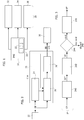
Figure 1 shows an embodiment of a system for the Cross Traffic Alert in accordance with the present disclosure, -
Figure 2 shows an embodiment of the Cross Traffic Alert method steps in accordance with the present disclosure; -
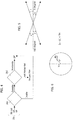
Figures 3 and4 show an example of a possible implementation of some details of the method steps ofFigure 2 ; -
Figure 5 and 6 show an example of a possible implementation of some details of the steps ofFigure 4 , -
Figure 7A, 7B, 8A, 8B ,9A and 9B are example of outputs, respectively of the Clustering step and of the CTA system. - In the following description, numerous specific details are given to provide a thorough understanding of embodiments. The embodiments can be practiced without one or several specific details, or with other methods, components, materials, etc. In other instances, well-known structures, materials, or operations are not shown or described in detail to avoid obscuring aspects of the embodiments.
- Reference throughout this specification to "one embodiment" or "an embodiment" means that a particular feature, structure, or characteristic described in connection with the embodiment is included in at least one embodiment. Thus, the appearances of the phrases "in one embodiment" or "in an embodiment" in various places throughout this specification are not necessarily all referring to the same embodiment. Furthermore, the particular features, structures, or characteristics may be combined in any suitable manner in one or more embodiments.
- The headings provided herein are for convenience only and do not interpret the scope or meaning of the embodiments.
- In particular, the Cross Traffic Alert (CTA) system is able to detect vehicles that move into the vehicle driving path from the left or from the right side.
- The camera that acquires an image of the surrounding area is supposed to be not only on a vehicle still, e.g. stopped at a traffic light or at a road intersection, but also moving slowly, e.g. in a car park zone.
- Since a growing numbers of companies produce image sensors with hardware implemented Optical Flow (OF) analysis, as disclosed in A. A. Stocker and R. J. Douglas, "Analog integrated 2-D optical flow sensor with programmable pixels", Proceedings of the 2004 International Symposium on Circuits and Systems (ISCAS), 2004, the Cross Traffic Alert (CTA) system here described can work directly in the Image Signal Processor (ISP), internal to the image camera, avoiding to overload the Engine Control Unit (ECU) and avoiding to transmit the entire image flow, without the need to have an external image processor.
- It allows obtaining a real time Cross Traffic Alert (CTA) system with low extra computational effort, offering good performance.
-
Figure 1 shows a possible solution for a low-cost Cross Traffic Alert (CTA) system. - As mentioned before, the Cross Traffic Alert (CTA) system can work directly in the Image Signal Processor (ISP) of the Camera, without the need to have an external Image Processor.
- In the example considered, at least one
image camera 10 generating an image IMG is placed on a vehicle, such as a car, a truck or a motorcycle. Theimage camera 10 is placed on the vehicle and is configured to monitor the front, the back and/or the lateral road situation with respect to the vehicle. - The
image camera 10 comprises aprocessing module 20, for example a system for the Cross Traffic Alert analysis and the alert generation, that is adapted to analyze the road situation and produce an alert to the driver under some circumstances. - A typical detection system may therefore comprise a
camera 10, aprocessing module 20 and analert device 30, such as a visual display, an acoustic element and/or a haptic actuator. - Therefore, the alert given to the driver can be of different type. For example, the alert device may comprise an
audio element 32, adisplay element 34, and/or ahaptic actuator 36. - In particular, the haptic or kinesthetic communication recreates the sense of touch by applying forces, vibrations, or motions to the user, and in particular on the steering wheel of the vehicle.
- In various embodiments of the present disclosure, the alert can be the sum or the mixing of the acoustic, the visible and the haptic alert.
- In the embodiment considered, for example, the Cross Traffic Alert (CTA) system generates an output video showing the input scene where the detected vehicles or moving objects are surrounded by a Bounding Box BB (see for example
figure 7A ). - In particular, the Cross Traffic Alert (CTA) processing
module 20 is entirely based on the Optical Flow (OF), e.g. the collection of Motion Vectors (MVs) indicating the motion of a feature in the current frame compared with the same feature in the previous frame. - The Optical Flow (OF) is computed directly inside the Image Signal Processor (ISP) of the
camera 10, for example by theprocessing module 20, ensuring a real time processing. - More to the point, the Cross Traffic Alert (CTA) system uses only the Optical Flow (OF) available from sensors/ISP (for example by the new device sensor STV0991).
- Moreover, the sensor device STV0991 is an image signal processor with HardWare accelerators for video analytics (i.e. Optical Flow and Line Detector) working in parallel to embedded video encoders. A 500MHz ARM based CPU, an H264 video encoder and a small rendering engine enable real time applications. The Cross Traffic Alert (CTA) procedure runs on STV0991 CPU exploiting its embedded video analytics HW accelerator. In particular, only the Optical Flow is used.
- Moreover, as mentioned before, the Cross Traffic Alert (CTA) system does not need the image content, allowing to reduce the power consumption and the processor requirements, because it can work directly in a low resource system, i.e. directly in the Image Signal Processor (ISP) of the
camera 10. - This can avoid to overload the Engine Control Unit (ECU) and to transmit the entire image flow between the different modules of the system.
- The
processing module 20 comprises afirst module 22 configured to analyses the images IMG provided by thecamera 10 in order to generate Optical Flow data OF. For example, in various embodiments, the Optical Flow data OF include a collection/list of Motion Vectors (MV) indicating the motion of respective features in the current image/frame compared with the previous image/frame. The Optical Flow data OF are computed in hardware, thereby permitting a real time processing with, e.g., 30 fps. - Commonly, the computation of Optical Flow data OF, in particular of Motion Vectors, is well known in the art, rendering a more detailed description herein unnecessary.
- In the embodiment considered, the Cross Traffic Alert (CTA) processing
module 20 receives the Optical Flow data OF, e.g. the motion vectors MV, having been estimated by themodule 22. - In one or more embodiments as exemplified in
Figure 2 , theprocessing module 20 execute the following steps of a Cross Traffic Alert (CTA) procedure that may include: - calculating in a
module 24 the Vanishing Point VP starting from the Optical Flow data OP estimated by themodule 22; this steps takes in input the Optical Flow data OF, and calculates the Vanishing Point VP, e.g. the mean point of all intersections of straight lines passing through zoom vectors (vectors lying in the road); - calculating in a
module 26 the Horizontal Filter OF' subset; taking into account the Vanishing Point VP calculated in themodule 24 and the Bound Box BB List of previous frame (received in input as a feedback reaction), filters from the total Optical Flow OF the horizontal Motion Vectors MVs, obtaining a subset of Optical Flow OF, called OF' subset; - in a
Clustering module 28 the subset OF' of Optical Flow is clustered and generating the Bound Box BB List that is sent to theAlert Generation device 30; from the subset OF' take out from the Optical Flow OF, retrieves moving objects in a scene, assuming a stationary camera, and obtaining a BB List as output. - More in details, in the following subparagraphs the aforementioned steps will be described in details.
- First of all, the
processing module 20 calculates the Vanishing Point VP using module the VanishingPoint 24. - One of the most useful information for the scene understanding is the position of the Vanishing Point VP. From a theoretical point of view, the Vanishing Point VP position into the scene overlaps the centre of the image only in a case of an ideal situation: a road perfectly plane (no slopes and no curves), a forward camera placed horizontally to the ground (no tilt angle) and perpendicularly to the main car axis (no pan angle).
- The real case (this is the target scenario for the proposed application) presents camera calibration parameters different to zero (for example tilt and pan angles) and, mainly, the host car crosses through roads which can have slopes and curves.
- Therefore, in a real environment, the Vanishing Point VP position does not coincide with the centre of the image and for this reason it is estimated.
- In one or more embodiments the Vanishing Point VP position is important not only because delimits the horizon of the scene, but also because it contributes to the selection of the Motion Vectors MVs potentially belonging to a crossing vehicle in the next Horizontal Filter sub-block.
- In one or more embodiments the Vanishing Point VP is computed using only the OF.
- Some or all of the processing steps of the procedure are exemplified in
Figure 3 . The steps can be synthetized as follows: - in a
step 240 the Optical Flow OF received in input by themodule 24 is filtered in a Zoom-out filter module 240; according to the orientation, only the Motion Vectors MVs laying on the road are selected and collected in order e to constituting a reduced set indicated by OF"; - in a
step 242 the Vanishing Point VP is calculated for each frame as the average position of all intersections among lines generated by directions of Motion Vectors MVs belonging to the reduced set OF"; the output of thisstep 242 is the Vanishing Point VP; see for example document N. Takeda and M. Watanabe, "Device and method for detection of moving obstacles",US 5777690 A, 1998 ; - in a
step 244 the Vanishing Point VP is checked; the Vanishing Point VP position estimated in the current frame will contribute to the Vanishing Point VP temporal position estimation only if it passes a specific check; overlying a 3x3 grid over the image, if the Vanishing Point VP position of the current frame belongs to the central area of the grid, than it will be used for the temporal average, otherwise it will be discarded in astep 248; - in a
step 246 the validated Vanishing Point VP position is submitted to a Temporal Averaging ; the arithmetic media between the valid Vanishing Point VP positions relative to subsequent frames is calculated; see for example document M. Jähnisch, M. Siebeneicher, A. Fietz, A. Haja, D. Liebehenschel and C. Söhnel, "Method and apparatus for calibration of a camera system of a motor vehicle",DE102014209137 A1, 2015 ; due to the presence of outlier in the zoom-out set OF", the subsequent Vanishing Point VP positions can be slightly different; the temporal approach allows smoothing these differences ensuring a more reliable and steady Vanishing Point VP point; the temporal Vanishing Point VP position is initialized to the centre of the image plane and it reaches its stable position in few frames (around 10 frames). - Moreover, the
processing module 20 calculates the subset OF' using theHorizontal Filter module 26 and receiving in input the Optical Flow OF and the Vanishing Point VP. Furthermore, also the Bound Box BB List generated by theClustering module 28 is received in input as a feedback reaction. - In order to let the
subsequent Clustering step 28 correctly work, since it works only with steady camera, it is important to remove the Motion Vectors MVs that are in the same direction of the vehicle movement, filtering the horizontal Motion Vectors MVs. - Therefore, the
processing module 20 is configured for apply a filtering based on the Bound Box BB List of previous frame, Vanishing Point VP and Motion Vectors MVs orientations. - In particular, as indicated in
Figure 4 , theHorizontal Filter module 26 acts according to the following steps: - BB Check step 260: the Motion Vectors MVs inside the previous calculated Bound Box BB List are preserved, and maintained in the subset OF', to avoid eliminating true clusters in the
next Clustering step 28; of course, these Motion Vectors MVs can be motion compensated, assuming a constant speed in the scene; the Motion Vectors MVs in vehicles on the left side of the scene moving to the left (and vehicles on the right side of the scene moving to the right) can be easily confused with the Motion Vectors MVs to be eliminated; introducing theBB Check step 260, let to overcome the problem, assuming that vehicles on the left side of the scene moving to the left (and vehicles on the right side of the scene moving to the right) have been previously in the scene moving starting from opposite side of the scene and then previously identified byClustering step 28; - Horizontal Check step 262: the Motion Vectors MVs outside the previous calculated Bound Box BB List are checked and the horizontal Motion Vectors MVs are filtered;
- 1) its orientation lies around an horizontal orientation (zero or 180 degree), as indicated in
Figure 5 ; in the example the angle is θ=ρ=10 degree; and - 2) the orientation difference between the Motion Vector MV orientation and the orientation of the Motion Vector MV translated on Vanishing Point VP overcomes an evaluated dynamic threshold TH, as indicated in
Figure 6 ; this dynamic threshold TH can be valuated as percentage of the difference between maximum and minimum orientation lying around the considered Motion Vector MV; in particular, for each Motion Vectors MV the neighbourhood considered is set to ±1 in both directions. - In particular, the
Clustering module 28 receives the subset OF' form theHorizontal Filter module 26 and calculates the Bound Box BB List. - More to the point, Clustering is the task of grouping a set of information in such a way that information in the same group (called a cluster) are more similar to each other than to those in other groups.
- In this application is important to identify moving cars transversally approaching the monitored vehicle on which the Cross Traffic Alert (CTA) system is installed.
- The Clustering step applied in
module 28 is based, as mentioned before, only on the Optical Flow analysis, which came from previousHorizontal Filter step 26. For example, in one or more embodiments theClustering step 28 can be implemented as disclosed in document G. Spampinato, A. Bruna, V. D'Alto, "A clustering method and system, corresponding apparatus and computer program product", application N.102015000082886 - Lots of tests have been executed with different scenarios and different cameras at different resolutions, with both linear and fish-eye lens, obtaining really good visual results.
- For real-time testing, the applicant have used the STMicroelectronics device STV0991, the specific of which can be found at the internet web site http://www.st.com/web/catalog/mmc/FM132/SC51/PF255756.
- This device is an image processor having not only the classic pipeline to reconstruct the image from a Bayer image, but also it embeds the Optical Flow, which can directly used as input for the cross traffic alert method.
- In this image processor, there is an embedded ARM Cortex-R4 CPU @500MHz, therefore the method can be loaded directly on it, without external host processors, having in the chip the complete solution to test "live" the behaviour of the cross traffic alert method.
- An example of Rear Cross Traffic Alert CTA with fish-eye camera is shown in
Figure 7A and Figure 7B . In the Rear Cross Traffic Alert CTA case, the camera is mounted on the back of the vehicle and in this case the vehicle is backing out of the parking spaces. - The output of just the
Clustering step 28 represented inFigure 7A shows false Bound Boxes BBs on the ground, since the camera is mounted in a moving car and lines on the ground are moving. On the contrary, with the proposed Cross Traffic Alert CTA method, represented inFigure 7B , the false Bound Boxes BBs are removed, since they are correctly identified and removed by theHorizontal Filter step 26. - Moreover, another example of slow crossroad arriving with linear camera is shown in
Figure 8A and Figure 8B . - In this case, the camera is mounted in front of the vehicle and the vehicle is approaching to a crossroad. The output of just the
Clustering step 28, represented inFigure 8A , shows false Bound Boxes BBs on the ground, on the leaves of trees and in the road sign. - Conversely, with the proposed Cross Traffic Alert CTA method, represented in
Figure 8B all the false Bound Boxes BBs are removed, leaving the Bound Boxes BBs of the two crossing cars. - Furthermore, another example of slow crossroad leaving with linear camera is shown in
Figure 9A and Figure 9B . - In this case, the camera is mounted in front of the vehicle and the vehicle is leaving a crossroad. The output of just the
Clustering step 28, represented inFigure 9A , shows false Bound Boxes BBs on the ground and on the leaves of trees. - Conversely, with the proposed Cross Traffic Alert CTA method, represented in
Figure 9B , all the false Bound Boxes BBs are removed, leaving the Bound Boxes BBs of the crossing car. - The proposed solution has been experimentally tested on a representative dataset of scenes obtaining effective results in terms of accuracy. In particular, lots of tests have been executed with different scenarios and different cameras obtaining really good visual results. For example, Linear and Fish-eye lens and different cameras and resolutions have been tested.
- A very reliable and low-cost Cross Traffic Alert CTA method has been developed with the following characteristics:
- is a very simple technique;
- low power consumption;
- no external Image Processor needed;
- no additional memory requirement; and
- the proposed method is very flexible, so can be used with any algorithm for Optical Flow OF, Vanishing Point VP calculation and Clustering operation.
- In particular, the computation time is about 800 frame/sec for a VGA sequence on a 2.3GHz processor (like an ARM Cortex-A15).
- The system is deterministic, i.e. the same input produces always the same output.
- All the Cross Traffic Alert CTA processing is inside the ISP of the Camera, and moreover for solution detectability can be used:
- ad-hoc input/output stimuli,
- test sequences with random small/medium noise,
- test sequences with multiple objects crossing.
- Of course, without prejudice to the principle of the invention, the details of construction and the embodiments may vary widely with respect to what has been described and illustrated herein purely by way of example, without thereby departing from the scope of the present invention, as defined by the ensuing claims.
Claims (8)
- A method for Cross Traffic Alert comprising the steps of:- receiving a sequence of images (IMG) from a camera (10) mounted on a vehicle;- processing (20) said sequence of images (IMG) in order to generate Optical Flow data (OF) comprising a list of Motion Vectors being associated with respective features in said sequence of images (IMG);- analyzing said Optical Flow data (OF) in order to calculate (24) the Vanishing Point (VP) by calculating the mean point of all intersections of straight lines passing through vectors lying in the road;- calculating (26) an Horizontal Filter subset (OF') taking into account the Vanishing Point (VP) and a list of Bound Box (BB) of previous frame and filtering from the Optical Flow (OF) the horizontal Motion Vectors;- Clustering (28) the subset (OF') of Optical Flow and generating the Bound Box (BB) list retrieving the moving objects in a scene, wherein said list is sent to an Alert Generation device (30); and- generating an output video showing the input scene where the detected moving objects are surrounded by a Bounding Box (BB).
- The method for Cross Traffic Alert according to claim 1, comprising the steps of:- filtering (240) the Optical Flow (OF) according to the orientation, and selecting only the Motion Vectors (MV) laying on the road in order to form a reduced set (OF");- calculating (242) the Vanishing Point (VP) for each frame as the average position of all intersections among lines generated by directions of Motion Vectors (MV) belonging to the reduced set (OF");- checking (244) the Vanishing Point (VP) and estimating the Vanishing Point VP position in the current frame;- overlying a grid over the image if the Vanishing Point (VP) position of the current frame belongs to the central area of the grid; and- calculating (246) the arithmetic media between the valid Vanishing Point VP positions relative to subsequent frames.
- The method for Cross Traffic Alert according to claim 1 or claim 2, in which calculating (26) the Horizontal Filter subset (OF') comprises the steps of:- checking the BB (260) and maintaining in said subset (OF') the Motion Vectors (MV) inside the previous calculated Bound Box (BB) List;- performing an Horizontal Check (262) wherein the Motion Vectors (MV) outside the previous calculated Bound Box (BB) List are checked and the horizontal Motion Vectors MVs are filtered and if the Motion Vector (MV) is considered Horizontal in maintained in the subset (OF'), otherwise is discarded.
- The method for Cross Traffic Alert according to claim 3, wherein a Motion Vector (MV) is considered horizontal, if the two conditions are both satisfied:- the orientation of the Motion Vector (MV) lies around an horizontal orientation; and- the orientation difference between the Motion Vector (MV) orientation and the orientation of the Motion Vector (MV) translated on Vanishing Point (VP) overcomes an evaluated dynamic threshold (TH).
- The method for Cross Traffic Alert according to claim 4, wherein said dynamic threshold (TH) can be valuated as percentage of the difference between maximum and minimum orientation lying around the considered Motion Vector (MV) and in particular, for each Motion Vectors (MV) the neighbourhood considered is set to ±1 in both directions.
- A processing system being configured to perform the method according to any of the previous claims.
- A Cross Traffic Alert system comprising a camera (10), an Alert Generation device (30) and a processing system according to claim 6.
- A vehicle comprising a Cross Traffic Alert system according to claim 7.
Applications Claiming Priority (1)
| Application Number | Priority Date | Filing Date | Title |
|---|---|---|---|
| IT102016000094858A IT201600094858A1 (en) | 2016-09-21 | 2016-09-21 | PROCEDURE FOR A LOW COST ADVANCED CROSS TRAFFIC ALERT, CORRESPONDING PROCESSING SYSTEM, CROSS TRAFFIC ALERT AND VEHICLE SYSTEM |
Publications (1)
| Publication Number | Publication Date |
|---|---|
| EP3299994A1 true EP3299994A1 (en) | 2018-03-28 |
Family
ID=57796883
Family Applications (1)
| Application Number | Title | Priority Date | Filing Date |
|---|---|---|---|
| EP17162248.3A Withdrawn EP3299994A1 (en) | 2016-09-21 | 2017-03-22 | A method for advanced and low cost cross traffic alert, related processing system, cross traffic alert system and vehicle |
Country Status (4)
| Country | Link |
|---|---|
| US (1) | US10242272B2 (en) |
| EP (1) | EP3299994A1 (en) |
| CN (1) | CN107845290B (en) |
| IT (1) | IT201600094858A1 (en) |
Cited By (1)
| Publication number | Priority date | Publication date | Assignee | Title |
|---|---|---|---|---|
| GB2598082A (en) * | 2020-07-08 | 2022-02-23 | Continental Automotive Gmbh | Road mirror detection system and method |
Families Citing this family (14)
| Publication number | Priority date | Publication date | Assignee | Title |
|---|---|---|---|---|
| JP6930120B2 (en) * | 2017-02-02 | 2021-09-01 | 株式会社リコー | Display device, mobile device and display method. |
| US11017249B2 (en) * | 2018-01-29 | 2021-05-25 | Futurewei Technologies, Inc. | Primary preview region and gaze based driver distraction detection |
| JP2019156180A (en) * | 2018-03-13 | 2019-09-19 | 本田技研工業株式会社 | Vehicle controller, vehicle control method and program |
| KR102047303B1 (en) * | 2018-06-01 | 2019-11-21 | 엘지전자 주식회사 | Robot of estimating direction based on vanishing point of low luminance image and method estimating thereof |
| SG11202111248UA (en) * | 2018-06-13 | 2021-11-29 | Ride Vision Ltd | A rider assistance system and method |
| KR102707596B1 (en) * | 2018-08-07 | 2024-09-19 | 삼성전자주식회사 | Device and method to estimate ego motion |
| US11315256B2 (en) * | 2018-12-06 | 2022-04-26 | Microsoft Technology Licensing, Llc | Detecting motion in video using motion vectors |
| US11055543B2 (en) * | 2019-07-26 | 2021-07-06 | Volkswagen Ag | Road curvature generation in real-world images as a method of data augmentation |
| KR102946953B1 (en) * | 2019-12-10 | 2026-04-01 | 팅크웨어(주) | Vehicle terminal device, service server, method, computer program, computer readable recording medium for providing driving related guidance service |
| JP7327324B2 (en) * | 2020-08-31 | 2023-08-16 | いすゞ自動車株式会社 | alarm device |
| JP7416348B1 (en) * | 2022-03-11 | 2024-01-17 | 三菱電機株式会社 | Movement direction determination device, movement direction determination method, and movement direction determination program |
| CN115082701B (en) * | 2022-08-16 | 2022-11-08 | 山东高速集团有限公司创新研究院 | Multi-water-line cross identification positioning method based on double cameras |
| US12600182B2 (en) * | 2022-11-07 | 2026-04-14 | Fca Us Llc | Self propelled trailer systems |
| KR20250027116A (en) * | 2023-08-18 | 2025-02-25 | 삼성전자주식회사 | Method and device for determining heading direction of a target vehicle |
Citations (6)
| Publication number | Priority date | Publication date | Assignee | Title |
|---|---|---|---|---|
| US5777690A (en) | 1995-01-20 | 1998-07-07 | Kabushiki Kaisha Toshiba | Device and method for detection of moving obstacles |
| US20080306666A1 (en) | 2007-06-05 | 2008-12-11 | Gm Global Technology Operations, Inc. | Method and apparatus for rear cross traffic collision avoidance |
| US20100201508A1 (en) | 2009-02-12 | 2010-08-12 | Gm Global Technology Operations, Inc. | Cross traffic alert system for a vehicle, and related alert display method |
| US20110133917A1 (en) | 2009-12-03 | 2011-06-09 | Gm Global Technology Operations, Inc. | Cross traffic collision alert system |
| US20140015693A1 (en) | 2011-09-26 | 2014-01-16 | Toyota Jidosha Kabushiki Kaisha | Rear cross traffic alert device |
| DE102014209137A1 (en) | 2014-05-14 | 2015-11-19 | Volkswagen Aktiengesellschaft | Method and device for calibrating a camera system of a motor vehicle |
Family Cites Families (37)
| Publication number | Priority date | Publication date | Assignee | Title |
|---|---|---|---|---|
| JPH04118360A (en) * | 1990-09-06 | 1992-04-20 | Daido Signal Co Ltd | Crossing obstruction detector |
| JPH08329398A (en) * | 1995-05-30 | 1996-12-13 | Nissan Motor Co Ltd | Road detection device |
| JPH1091795A (en) * | 1996-09-12 | 1998-04-10 | Toshiba Corp | Moving object detecting device and moving object detecting method |
| US6993159B1 (en) * | 1999-09-20 | 2006-01-31 | Matsushita Electric Industrial Co., Ltd. | Driving support system |
| JP2001213254A (en) * | 2000-01-31 | 2001-08-07 | Yazaki Corp | Vehicle side monitoring system |
| US6501794B1 (en) * | 2000-05-22 | 2002-12-31 | Microsoft Corporate | System and related methods for analyzing compressed media content |
| JP3521860B2 (en) * | 2000-10-02 | 2004-04-26 | 日産自動車株式会社 | Vehicle travel path recognition device |
| US7266220B2 (en) * | 2002-05-09 | 2007-09-04 | Matsushita Electric Industrial Co., Ltd. | Monitoring device, monitoring method and program for monitoring |
| US7409092B2 (en) * | 2002-06-20 | 2008-08-05 | Hrl Laboratories, Llc | Method and apparatus for the surveillance of objects in images |
| JP3904988B2 (en) * | 2002-06-27 | 2007-04-11 | 株式会社東芝 | Image processing apparatus and method |
| EP1662459A4 (en) * | 2003-09-02 | 2007-03-21 | Fujitsu Ltd | ONBOARD DEVICE FOR PROCESSING IMAGES |
| JP4052650B2 (en) * | 2004-01-23 | 2008-02-27 | 株式会社東芝 | Obstacle detection device, method and program |
| JP3931885B2 (en) * | 2004-02-16 | 2007-06-20 | 日産自動車株式会社 | Obstacle detection device |
| US7248718B2 (en) * | 2004-02-19 | 2007-07-24 | Siemens Corporate Research, Inc. | System and method for detecting a passing vehicle from dynamic background using robust information fusion |
| JP3846494B2 (en) * | 2004-07-13 | 2006-11-15 | 日産自動車株式会社 | Moving obstacle detection device |
| US7639841B2 (en) * | 2004-12-20 | 2009-12-29 | Siemens Corporation | System and method for on-road detection of a vehicle using knowledge fusion |
| JP2006268097A (en) * | 2005-03-22 | 2006-10-05 | Nissan Motor Co Ltd | On-vehicle object detection device and object detection method |
| US8605947B2 (en) * | 2008-04-24 | 2013-12-10 | GM Global Technology Operations LLC | Method for detecting a clear path of travel for a vehicle enhanced by object detection |
| US8487991B2 (en) * | 2008-04-24 | 2013-07-16 | GM Global Technology Operations LLC | Clear path detection using a vanishing point |
| US8699754B2 (en) * | 2008-04-24 | 2014-04-15 | GM Global Technology Operations LLC | Clear path detection through road modeling |
| JP5074365B2 (en) * | 2008-11-28 | 2012-11-14 | 日立オートモティブシステムズ株式会社 | Camera device |
| US8812226B2 (en) * | 2009-01-26 | 2014-08-19 | GM Global Technology Operations LLC | Multiobject fusion module for collision preparation system |
| JP5483535B2 (en) * | 2009-08-04 | 2014-05-07 | アイシン精機株式会社 | Vehicle periphery recognition support device |
| CN102110296A (en) * | 2011-02-24 | 2011-06-29 | 上海大学 | Method for tracking moving target in complex scene |
| CN102157072B (en) * | 2011-03-29 | 2013-03-20 | 北京航空航天大学 | Inducing device and inducing method of vehicle confluence at intersection based on vehicle and road crossing |
| CN102592454A (en) * | 2012-02-29 | 2012-07-18 | 北京航空航天大学 | Intersection vehicle movement parameter measuring method based on detection of vehicle side face and road intersection line |
| JP6197291B2 (en) * | 2012-03-21 | 2017-09-20 | 株式会社リコー | Compound eye camera device and vehicle equipped with the same |
| JP5867273B2 (en) * | 2012-04-27 | 2016-02-24 | 富士通株式会社 | Approaching object detection device, approaching object detection method, and computer program for approaching object detection |
| US9460354B2 (en) * | 2012-11-09 | 2016-10-04 | Analog Devices Global | Object detection |
| KR102077498B1 (en) * | 2013-05-13 | 2020-02-17 | 한국전자통신연구원 | Movement path extraction devices of mutual geometric relations fixed camera group and the method |
| US8977060B2 (en) * | 2013-05-16 | 2015-03-10 | Microsoft Technology Licensing, Llc | Motion stabilization and detection of articulated objects |
| CN103942560B (en) * | 2014-01-24 | 2017-06-16 | 北京理工大学 | A kind of high-resolution video vehicle checking method in intelligent traffic monitoring system |
| US9664789B2 (en) * | 2014-02-20 | 2017-05-30 | Mobileye Vision Technologies Ltd. | Navigation based on radar-cued visual imaging |
| CN106663193B (en) * | 2014-05-14 | 2020-12-25 | 御眼视觉技术有限公司 | System and method for curb detection and pedestrian hazard assessment |
| JP5949861B2 (en) * | 2014-09-05 | 2016-07-13 | トヨタ自動車株式会社 | Vehicle approaching object detection device and vehicle approaching object detection method |
| CN105574552A (en) * | 2014-10-09 | 2016-05-11 | 东北大学 | Vehicle ranging and collision early warning method based on monocular vision |
| KR102366402B1 (en) * | 2015-05-21 | 2022-02-22 | 엘지전자 주식회사 | Driver assistance apparatus and control method for the same |
-
2016
- 2016-09-21 IT IT102016000094858A patent/IT201600094858A1/en unknown
-
2017
- 2017-03-22 EP EP17162248.3A patent/EP3299994A1/en not_active Withdrawn
- 2017-03-27 CN CN201710190150.7A patent/CN107845290B/en active Active
- 2017-03-28 US US15/471,138 patent/US10242272B2/en active Active
Patent Citations (6)
| Publication number | Priority date | Publication date | Assignee | Title |
|---|---|---|---|---|
| US5777690A (en) | 1995-01-20 | 1998-07-07 | Kabushiki Kaisha Toshiba | Device and method for detection of moving obstacles |
| US20080306666A1 (en) | 2007-06-05 | 2008-12-11 | Gm Global Technology Operations, Inc. | Method and apparatus for rear cross traffic collision avoidance |
| US20100201508A1 (en) | 2009-02-12 | 2010-08-12 | Gm Global Technology Operations, Inc. | Cross traffic alert system for a vehicle, and related alert display method |
| US20110133917A1 (en) | 2009-12-03 | 2011-06-09 | Gm Global Technology Operations, Inc. | Cross traffic collision alert system |
| US20140015693A1 (en) | 2011-09-26 | 2014-01-16 | Toyota Jidosha Kabushiki Kaisha | Rear cross traffic alert device |
| DE102014209137A1 (en) | 2014-05-14 | 2015-11-19 | Volkswagen Aktiengesellschaft | Method and device for calibrating a camera system of a motor vehicle |
Non-Patent Citations (18)
| Title |
|---|
| A. A. STOCKER; R. J. DOUGLAS: "Analog integrated 2-D optical flow sensor with programmable pixels", PROCEEDINGS OF THE 2004 INTERNATIONAL SYMPOSIUM ON CIRCUITS AND SYSTEMS (ISCAS, 2004 |
| A. CHOUDHARY; Y. MOON; R. NAWKHARE: "Design and Implementation of Wireless Security System in Vehicle", INTERNATIONAL JOURNAL OF INNOVATIVE RESEARCH IN COMPUTER AND COMMUNICATION ENGINEERING, 2015 |
| B. F. WU; C. C. KAO; Y. F. LI; M. Y. TSAI: "A Real-Time Embedded Blind Spot Safety Assistance System", INTERNATIONAL JOURNAL OF VEHICULAR TECHNOLOGY, 2012 |
| B. REIMER; B. MEHLER; J. F. COUGHLIN: "An Evaluation of Driver Reactions to New Vehicle Parking Assist Technologies Developed to Reduce Driver Stress", NEW ENGLAND UNIVERSITY TRANSPORTATION CENTER, 2010 |
| E. DAGAN; 0. MANO; G. P. STEIN; A. SHASHUA: "Forward collision warning with a single camera", IEEE INTELLIGENT VEHICLES SYMPOSIUM, 2004 |
| E. SALARI; D. OUYANG: "Camera-based Forward Collision and lane departure warning systems using SVM", IEEE 56TH INTERNATIONAL MIDWEST SYMPOSIUM ON CIRCUITS AND SYSTEMS (MWSCAS, 2013 |
| IKURO SATO ET AL: "Crossing obstacle detection with a vehicle-mounted camera", INTELLIGENT VEHICLES SYMPOSIUM (IV), 2011 IEEE, IEEE, 5 June 2011 (2011-06-05), pages 60 - 65, XP031998914, ISBN: 978-1-4577-0890-9, DOI: 10.1109/IVS.2011.5940404 * |
| J. CUI; F. LIU; Z. LI; Z. JIA: "Vehicle Localisation Using a Single Camera", IEEE INTELLIGENT VEHICLES SYMPOSIUM, 2010 |
| J. THOMANEK; G. WANIELIK: "A new pixel-based fusion framework to enhance object detection in automotive applications", 17TH INTERNATIONAL CONFERENCE ON INFORMATION FUSION (FUSION, 2014 |
| LEFAIX G ET AL: "Motion-based obstacle detection and tracking for car driving assistance", PATTERN RECOGNITION, 2002. PROCEEDINGS. 16TH INTERNATIONAL CONFERENCE ON QUEBEC CITY, QUE., CANADA 11-15 AUG. 2002, LOS ALAMITOS, CA, USA,IEEE COMPUT. SOC, US, vol. 4, 11 August 2002 (2002-08-11), pages 74 - 77, XP010613474, ISBN: 978-0-7695-1695-0, DOI: 10.1109/ICPR.2002.1047403 * |
| P. SHAKOURI; J. CZECZOT; A. ORDYS: "Adaptive Cruise Control System using Balance-Based Adaptive Control technique", 17TH INTERNATIONAL CONFERENCE ON METHODS AND MODELS IN AUTOMATION AND ROBOTICS (MMAR, 2012 |
| R. TAN: "A safety concept for camera based ADAS based on multicore MCU", IEEE INTERNATIONAL CONFERENCE ON VEHICULAR ELECTRONICS AND SAFETY (ICVES, 2014 |
| S. JEONG; T. KIM; J. LEE; S. LEE; J.LEE: "Design analysis of precision Navigation System", 12TH INTERNATIONAL CONFERENCE ON CONTROL, AUTOMATION AND SYSTEMS (ICCAS, 2012 |
| T. AUNG; M. H. ZAW: "Video Based Lane Departure Warning System", INTERNATIONAL CONFERENCE ON ADVANCES IN ENGINEERING AND TECHNOLOGY, 2014 |
| V. BALISAVIRA; V. K. PANDEY: "Real-time Object Detection by Road Plane Segmentation Technique for ADAS", EIGHTH INTERNATIONAL CONFERENCE ON SIGNAL IMAGE TECHNOLOGY AND INTERNET BASED SYSTEMS (SITIS, 2012 |
| Y. DENG; H. LIANG; Z. WANG; J. HUANG: "An integrated forward collision warning system based on monocular vision", IEEE INTERNATIONAL CONFERENCE ON ROBOTICS AND BIOMIMETICS (ROBIO, 2014 |
| Y. JHENG; Y. YEN; T. SUN: "A symmetry-based forward vehicle detection and collision warning system on Android smartphone", IEEE INTERNATIONAL CONFERENCE ON CONSUMER ELECTRONICS - TAIWAN (ICCE-TW, 2015 |
| YAMAGUCHI K ET AL: "Moving Obstacle Detection using Monocular Vision", 2006 IEEE INTELLIGENT VEHICLES SYMPOSIUM : MEGURO-KU, JAPAN, 13 - 15 JUNE 2006, IEEE, PISCATAWAY, NJ, USA, 13 June 2006 (2006-06-13), pages 288 - 293, XP010937028, ISBN: 978-4-901122-86-3, DOI: 10.1109/IVS.2006.1689643 * |
Cited By (1)
| Publication number | Priority date | Publication date | Assignee | Title |
|---|---|---|---|---|
| GB2598082A (en) * | 2020-07-08 | 2022-02-23 | Continental Automotive Gmbh | Road mirror detection system and method |
Also Published As
| Publication number | Publication date |
|---|---|
| US20180082132A1 (en) | 2018-03-22 |
| US10242272B2 (en) | 2019-03-26 |
| IT201600094858A1 (en) | 2018-03-21 |
| CN107845290B (en) | 2021-07-27 |
| CN107845290A (en) | 2018-03-27 |
Similar Documents
| Publication | Publication Date | Title |
|---|---|---|
| US10242272B2 (en) | Method for advanced and low cost cross traffic alert, related processing system, cross traffic alert system and vehicle | |
| US11657604B2 (en) | Systems and methods for estimating future paths | |
| JP7472170B2 (en) | Intersection Pose Detection in Autonomous Machine Applications | |
| CN111695717B (en) | Prediction of temporal information in autonomous machine applications | |
| CN115136148B (en) | Projecting images captured using fish-eye lenses for feature detection in autonomous machine applications | |
| CN107845104B (en) | Method for detecting overtaking vehicle, related processing system, overtaking vehicle detection system and vehicle | |
| US10810754B2 (en) | Simultaneous localization and mapping constraints in generative adversarial networks for monocular depth estimation | |
| CN108638999B (en) | Anti-collision early warning system and method based on 360-degree look-around input | |
| JP7144398B2 (en) | Camera device and method for capturing surrounding areas of self-vehicle | |
| WO2019241022A1 (en) | Path detection for autonomous machines using deep neural networks | |
| US20190281235A1 (en) | Camera Device and Method for Capturing a Surrounding Region of a Vehicle in a Situation-Adapted Manner | |
| CN107306338A (en) | Panoramic camera system for object detection and tracking | |
| DE112018004507T5 (en) | INFORMATION PROCESSING DEVICE, MOTION DEVICE AND METHOD AND PROGRAM | |
| US20220198203A1 (en) | Three dimensional traffic sign detection | |
| JP2020065141A (en) | Vehicle overhead image generation system and method thereof | |
| Rill et al. | Collision avoidance using deep learning-based monocular vision | |
| CN113609888A (en) | Object detection with planar homography and self-supervised scene structure understanding | |
| Viswanathan et al. | Applications of image processing and real-time embedded systems in autonomous cars: a short review | |
| Thakurdesai et al. | Computer vision based position and speed estimation for accident avoidance in driverless cars | |
| Kim et al. | An intelligent and integrated driver assistance system for increased safety and convenience based on all-around sensing | |
| Nikolić | Embedded vision in advanced driver assistance systems | |
| US12106492B2 (en) | Computer vision system for object tracking and time-to-collision | |
| US10936885B2 (en) | Systems and methods of processing an image | |
| US11919508B2 (en) | Computer vision system for object tracking and time-to-collision | |
| CN115578701A (en) | Method and apparatus and camera system for recognizing objects for a vehicle including a monocular camera |
Legal Events
| Date | Code | Title | Description |
|---|---|---|---|
| PUAI | Public reference made under article 153(3) epc to a published international application that has entered the european phase |
Free format text: ORIGINAL CODE: 0009012 |
|
| AK | Designated contracting states |
Kind code of ref document: A1 Designated state(s): AL AT BE BG CH CY CZ DE DK EE ES FI FR GB GR HR HU IE IS IT LI LT LU LV MC MK MT NL NO PL PT RO RS SE SI SK SM TR |
|
| AX | Request for extension of the european patent |
Extension state: BA ME |
|
| 17P | Request for examination filed |
Effective date: 20180816 |
|
| RBV | Designated contracting states (corrected) |
Designated state(s): AL AT BE BG CH CY CZ DE DK EE ES FI FR GB GR HR HU IE IS IT LI LT LU LV MC MK MT NL NO PL PT RO RS SE SI SK SM TR |
|
| 17Q | First examination report despatched |
Effective date: 20190716 |
|
| STAA | Information on the status of an ep patent application or granted ep patent |
Free format text: STATUS: THE APPLICATION HAS BEEN WITHDRAWN |
|
| 18W | Application withdrawn |
Effective date: 20190913 |