EP3299885A1 - Micro projector - Google Patents
Micro projector Download PDFInfo
- Publication number
- EP3299885A1 EP3299885A1 EP17193104.1A EP17193104A EP3299885A1 EP 3299885 A1 EP3299885 A1 EP 3299885A1 EP 17193104 A EP17193104 A EP 17193104A EP 3299885 A1 EP3299885 A1 EP 3299885A1
- Authority
- EP
- European Patent Office
- Prior art keywords
- component
- audio
- projection
- audio play
- projection component
- Prior art date
- Legal status (The legal status is an assumption and is not a legal conclusion. Google has not performed a legal analysis and makes no representation as to the accuracy of the status listed.)
- Granted
Links
Images
Classifications
-
- G—PHYSICS
- G03—PHOTOGRAPHY; CINEMATOGRAPHY; ANALOGOUS TECHNIQUES USING WAVES OTHER THAN OPTICAL WAVES; ELECTROGRAPHY; HOLOGRAPHY
- G03B—APPARATUS OR ARRANGEMENTS FOR TAKING PHOTOGRAPHS OR FOR PROJECTING OR VIEWING THEM; APPARATUS OR ARRANGEMENTS EMPLOYING ANALOGOUS TECHNIQUES USING WAVES OTHER THAN OPTICAL WAVES; ACCESSORIES THEREFOR
- G03B21/00—Projectors or projection-type viewers; Accessories therefor
-
- G—PHYSICS
- G03—PHOTOGRAPHY; CINEMATOGRAPHY; ANALOGOUS TECHNIQUES USING WAVES OTHER THAN OPTICAL WAVES; ELECTROGRAPHY; HOLOGRAPHY
- G03B—APPARATUS OR ARRANGEMENTS FOR TAKING PHOTOGRAPHS OR FOR PROJECTING OR VIEWING THEM; APPARATUS OR ARRANGEMENTS EMPLOYING ANALOGOUS TECHNIQUES USING WAVES OTHER THAN OPTICAL WAVES; ACCESSORIES THEREFOR
- G03B31/00—Associated working of cameras or projectors with sound-recording or sound-reproducing means
-
- H—ELECTRICITY
- H04—ELECTRIC COMMUNICATION TECHNIQUE
- H04R—LOUDSPEAKERS, MICROPHONES, GRAMOPHONE PICK-UPS OR LIKE ACOUSTIC ELECTROMECHANICAL TRANSDUCERS; ELECTRIC HEARING AIDS; PUBLIC ADDRESS SYSTEMS
- H04R1/00—Details of transducers, loudspeakers or microphones
- H04R1/02—Casings; Cabinets ; Supports therefor; Mountings therein
- H04R1/026—Supports for loudspeaker casings
-
- H—ELECTRICITY
- H04—ELECTRIC COMMUNICATION TECHNIQUE
- H04N—PICTORIAL COMMUNICATION, e.g. TELEVISION
- H04N9/00—Details of colour television systems
- H04N9/12—Picture reproducers
- H04N9/31—Projection devices for colour picture display, e.g. using electronic spatial light modulators [ESLM]
- H04N9/3141—Constructional details thereof
- H04N9/3173—Constructional details thereof wherein the projection device is specially adapted for enhanced portability
-
- H—ELECTRICITY
- H04—ELECTRIC COMMUNICATION TECHNIQUE
- H04R—LOUDSPEAKERS, MICROPHONES, GRAMOPHONE PICK-UPS OR LIKE ACOUSTIC ELECTROMECHANICAL TRANSDUCERS; ELECTRIC HEARING AIDS; PUBLIC ADDRESS SYSTEMS
- H04R1/00—Details of transducers, loudspeakers or microphones
- H04R1/02—Casings; Cabinets ; Supports therefor; Mountings therein
- H04R1/028—Casings; Cabinets ; Supports therefor; Mountings therein associated with devices performing functions other than acoustics, e.g. electric candles
-
- H—ELECTRICITY
- H04—ELECTRIC COMMUNICATION TECHNIQUE
- H04R—LOUDSPEAKERS, MICROPHONES, GRAMOPHONE PICK-UPS OR LIKE ACOUSTIC ELECTROMECHANICAL TRANSDUCERS; ELECTRIC HEARING AIDS; PUBLIC ADDRESS SYSTEMS
- H04R3/00—Circuits for transducers
- H04R3/12—Circuits for transducers for distributing signals to two or more loudspeakers
-
- H—ELECTRICITY
- H04—ELECTRIC COMMUNICATION TECHNIQUE
- H04R—LOUDSPEAKERS, MICROPHONES, GRAMOPHONE PICK-UPS OR LIKE ACOUSTIC ELECTROMECHANICAL TRANSDUCERS; ELECTRIC HEARING AIDS; PUBLIC ADDRESS SYSTEMS
- H04R2420/00—Details of connection covered by H04R, not provided for in its groups
- H04R2420/07—Applications of wireless loudspeakers or wireless microphones
Definitions
- the present disclosure relates to the field of projection technology, and more particularly to a micro projector.
- a projector or image projector is an optical device that projects an image (or moving images) onto a surface, commonly a projection screen. Most projectors create an image by shining a light through a small transparent lens, but some newer types of projectors can project the image directly, by using lasers. The most common type of projector used today is called a video projector. Video projectors are digital replacements for earlier types of projectors such as slide projectors and overhead projectors.
- a micro projector also known as a portable projector, pocket projector, or handheld projector, is an electronic device that that uses lasers or LEDs to project images. Generally, the micro projector is more compact than the traditional projector, with a higher degree of integration.
- micro projectors have integrated structures.
- Micro projectors are integrated with a projection component, an audio play component and a power supply component and other different functional components.
- the projection component is used to perform the function of a projector
- the audio play component is used to play audio
- the power supply component is used to supply power for the micro projector.
- the present disclosure provides a micro projector.
- the technical solution of the micro projector is provided as follows.
- a micro projector in a first aspect of the present disclosure, includes a projection component and at least one audio play component.
- the at least one audio play component is mounted to the projection component in a detachable way.
- an apparatus in a second aspect of the present disclosure, includes a projector housing for at least partially enclosing a projection apparatus configured to project video content.
- the apparatus further includes a first audio housing for at least partially enclosing an audio play apparatus configured to play audio accompanying the video content.
- the projector housing is detachably mounted to the first audio housing.
- the projection component is cylinder-shaped;
- the micro projector includes two audio play components, that is, a first audio play component and a second audio play component, each of the two audio play components is cylinder-shaped; and a first bottom surface of the projection component is connected with a bottom surface of the first the audio play component in a detachable way, a second bottom surface of the projection component is connected with a bottom surface of the second audio play component in the detachable way.
- each of the audio play components is prismatic-shaped; among side surfaces of the audio play component, at least one side surface is used to play audio and at least one side surface is not used to play audio.
- the projection component is prismatic-shaped; the first bottom surface and the second bottom surface of the projection component are octagonal-shaped; one of the side surfaces of the projection component is formed with a projection lens.
- At least one first recess portion is formed on the first bottom surface of the projection component, and at least one first protruding portion that matches with the first recess portion is formed on a bottom surface that is connected with the projection component of the first audio play component; at least one second recess portion is formed on the second bottom surface of the projection component, and at least one second protruding portion that matches with the second recess portion is formed on a bottom surface that is connected with the projection component of the second audio play component.
- the projection component and each of the first and second audio play components are provided with a battery unit, respectively.
- the projection component and each of the first and second audio play components are provided with charging interfaces for charging the respective battery units, respectively.
- At least one of the projection component and each of the first and second audio play components is provided with a charging interface for charging the respective battery units; and the battery units are electrically connected with each other by a charging contact.
- the detachable way is a magnetic attraction way.
- the projection component and at least one audio play component are provided with communication units.
- the projection component is provided with a first function button and a second function button; or alternatively, the projection component is provided with the first function button, and each of the first and second audio play components is provided with the second function button; and wherein the first function button is configured to control the projection component and the second function button is configured to control the audio play components.
- the technical solution provided by the present disclosure may include advantageous effects as follows.
- each audio play component is connected to the projection component in a detachable way; and the audio play components and the projection component can be placed separately after they are separated from each other.
- the audio play component does not have to be placed near the position of the projection component.
- the user may place the audio play component according to his/her needs, so as to ensure the sound quality perceived by the user.
- the present disclosure provides a micro projector.
- the embodiments of the present disclosure provide a technical solution, the core idea of which is to design a micro projector with a separable structure, in which the audio play components are connected with the projection component in a detachable way, so that the audio play components and the projection component can be placed separately after they are separated from each other.
- the audio play components do not have to be placed near the projection component, and the user may place the audio play components in appropriate positions according to his/her needs, so as to ensure the sound quality perceived by the user.
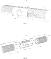
- FIG. 1 is a schematic structural diagram of a micro projector 10 in accordance with an exemplary embodiment.
- the micro projector 10 includes: a projection component 11 and at least one audio play component 12.
- Each audio play component 12 is mounted to the projection component 11 in a detachable way.
- the projection component 11 can be used to implement the projector function, which may include project video/image content to a surface.
- the projection component 11 may include a projection lens, a battery unit, a charging interface, function buttons, etc.
- the audio play component 12 is used to play audio.
- the audio play component may also be called a speaker component.
- the audio play component 12 may include speakers, mesh covers, function buttons, etc.
- each audio play component 12 is connected with the projection component 11 in a detachable way.
- the detachable way is a magnetic attraction way.
- magnets are provided on the connection surface of each component, and each component is connected with each other by means of a magnetic attraction.
- each audio play component 12 is detachably mounted to the projection component 11 by means of a magnetic attraction to facilitate separating and assembling components.
- the detachable way may be a screw connection method, a buckle connection method, etc., which is not limited in this embodiment.
- FIG. 2 shows the structural exploded view of an apparatus 10, which may be the micro projector.
- the apparatus 10 includes the projection component 11 and the audio play component 12.
- the projection component 11 includes a projector housing 11a for at least partially enclosing a projection apparatus configured to project video content.
- the audio play component 12 includes an audio housing 12a for at least partially enclosing an audio play apparatus configured to play audio accompanying the video content.
- the projection apparatus may include at least one hardware processor to decode video data, power supply to the at least one hardware processor, a lens, at least one communication chip, and other circuitries connecting the different hardware components.
- the audio play apparatus may include at least one hardware processor to decode audio data, power supply to the at least one hardware processor, a lens, at least one communication chip, and other circuitries connecting the different hardware components.
- all the hardware processors may be enclosed in the projector housing 11a.
- the micro projector 10 In the case of a magnetic attraction method, as long as the force applied on the audio play component 12 is greater than the magnetic attraction force between the projection component 11 and the audio play component 12, the micro projector 10 will be separated.
- the micro projector 10 is designed with a separable structure, so that the audio play component 12 and the projection component 11 can be placed separately, after they are separated from each other.
- the audio play component 12 need not be positioned near the projection component 11, and the user can freely select the position of the projection component 11 and the respective position of the audio play components 12 according to his/her needs, so as to obtain better projection effects and better sound quality effects.
- the micro projector 10 includes a plurality of audio play components 12 according to the present embodiment
- the plurality of audio play components 12 may be positioned at different places, respectively, so as to achieve a multi-point sound effect.
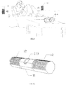
- FIG. 3 shows an application scenario of the micro projector provided in the present embodiment.
- the projection component 11 is column-shaped.
- the projection component 11 may be prismatic-shaped, or cylinder-shaped.
- the micro projector 10 includes two audio play components 12, that is, a first audio play component and a second audio play component (as shown in FIG. 1 and FIG. 2 , the audio play component on the left side is referred to as the first audio play component and that on the right side as the second audio play component).
- Each audio play component 12 is cylinder-shaped.
- the audio play components 12 may be prismatic-shaped, or it may be cylinder-shaped.
- micro projector 10, projection component 11 and each audio play component 12 may be formed in the same cylinder shape, so that each component can be better fitted and assembled.
- a first side surface 111 of the projection component 11 is connected with a bottom surface 121 of the first audio play component in a detachable way, and a second side surface 112 of the projection component 11 is mounted to a bottom surface 122 of the second audio play component in a detachable way.
- each of the audio play components 12 has a prismatic shape.
- a prismatic shape is a prism with a polygonal bottom, and has at least three sides.
- the prism may be a triangular prism, a quadrangular prism, pentagonal prism, and etc.
- at least one side surface 42 plays audio and at least one side surface 43 does not play audio.
- a side surface that is provided with audio play modules is referred to a side surface that plays audio
- a side surface that is not provided with audio play modules is referred to a side surface that does not play audio.
- An audio play module 12 may include a speaker 44 and a mesh cover 45. Each side surface 42 that plays audio is provided with a speaker 44, and a mesh cover 45 is provided on the periphery of the speaker 44.
- the mesh cover 45 has a mesh structure, in which small holes are uniformly distributed so as to prevent the speaker 44 from sound deterioration due to the effects of impurities, such as dusts, that enter into the speaker 44.
- the first audio play component and the second audio play component both have octagonal prism shapes, of which five sides are sound emitting sides (with small holes in the side, as shown in the figure) and the other three sides are not sound emitting sides (without any small hole in the side, as shown in the figure).
- the audio play component 12 when the audio play component 12 is lying on the side, it may be placed so that one side surface which is not a sound emitting side surface faces the table, and those sides that are sound emitting side surfaces face toward side directions and upward direction.
- the projection component 11 is formed in a prismatic-shape.
- the prismatic-shape may be a triangular prism, a quadrangular prism, a pentagonal prism, and etc.
- the projection component 11 and each audio play component 12 of the micro projector 10 are formed in the same column structure, such as a prismatic structure, the bottom of which is octagonal so that each component can be assembled and fitted conveniently.
- the first side surface and the second side surface of the projection component 11 are both regular octagonal.
- a projection lens 113 may be formed in one side of the projection component 11.
- the projection component 11 may be provided with a plurality of projection angles/directions when it is formed in a regular octagonal prism shape, such as, a horizontal direction, an oblique upward direction, and a vertical upward direction. The user can adjust the orientation of the projection lens 113 to obtain an appropriate projection angle according to the user's requirements.
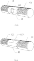
- FIGs. 4A-4C show several different orientations of the projection lens 113.
- the projection lens 113 in the FIG. 4A is placed in an obliquely upward direction
- the projection lens 113 shown in the FIG. 4B is placed in a vertical direction
- the projection lens 113 in the FIG. 4C faces a horizontal direction.
- At least one first recess portion 114 is disposed on the first side surface 111 of the projection component 11.
- At least one first protruding portion 124 that matches with the at least one first recess portion 114 is disposed on the bottom surface 121 that is connected with the projection component 11 of the first audio play component.
- At least one second recess portions (not shown) is disposed on the side surface 112 of the projection component 11.
- at least one second protruding portion 125 that matches with the at least one second recess portion is disposed on the bottom surface 122 that is connected with the projection component 11 of the second audio play component.
- the first protruding portion 124 and the second protruding portion 125 may be a cylindrical structure with a circular bottom surface or a prismatic structure with a polygonal bottom surface.
- the material of the first protruding portion 124 and the second protruding portion 125 may be selected from rubber, metal, etc. In this way, on one hand, it is possible to prevent the projection component 11 and the audio play component 12 from rotating freely after they are connected together. On the other hand, when the audio play component 12 is placed vertically, the audio play component 12 can be supported stably.
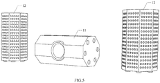
- FIG. 5 shows a placement diagram of the micro projector 10.
- the projection component 11 can be placed vertically or placed horizontally (as an example, the projection component 11 is shown horizontally in the FIG. 5 ). Any one of the exterior surfaces that is not provided with the projection lens 113 or function key can be used as a support surface facing the table.
- Two audio play components 12 can be placed vertically or horizontally (as an example, in FIG. 5 , the audio play components 12 are shown vertically). Any of its bottom surfaces or side surfaces can be used as a support surface facing the table.
- projection component 11 and each audio play component 12 are provided with the battery units, respectively.
- the components can work independently after they are separated from each other. This may help to increase the work duration of the micro projector 10.
- the projection component 11 and each audio play component 12 are provided with a charging interface for charging the respective battery unit so that each component can be independently charged.
- At least one of them is provided with a charging interface for charging the respective battery unit.
- Each battery unit is electrically connected by a charging contact.
- the charging contact is also referred to as a frequency point, being used to electrical connect the individual battery units to transmit power.
- at least one first charging contact (not shown) is provided on the first side surface 111 of the projection component 11, and a second charging contact (not shown) that mates with each of the at least one first charging contact is provided on the bottom surface that is mounted to the projection component 11.
- the second side surface 112 of the projection component 11 is provided with at least one third charging contact (not shown), and the bottom surface that is mounted to the projection component 11 of the second audio play component is provided with a fourth charging contact (not shown) which mates with each of the at least one third charging contact.
- only a single charging interface is provided on the projection component 11.
- the number of charging interfaces can be reduced, and the cost of micro projector 10 can be saved, too.
- the respective battery unit of every audio play component 12 and the battery unit of the projection component 11 may be charged.
- communication units are provided within the projection component 11 and at least one of the audio play components 12.
- the communication units are used to perform data communication between the components, and realize the cooperation between the projection component 11 and each audio play component 12.
- the communication unit may include a Bluetooth module, a Wi-Fi (Wireless Fidelity) module, or other hardware supporting wireless communication technology.
- projection component 11 is provided with first function button (or buttons) and second function button (or buttons) (as shown in FIG. 2 , first function buttons 115 and second function buttons 116). Or alternatively, the first function button (or buttons) is provided on the projection component 11, and the second function button (or buttons) is provided on at least one audio play component 12.
- the first function button is used to control the projection component 11, for example, the first function button may include a power switch button, a brightness adjustment button, a color adjustment button, a projection mode adjustment button, and etc.
- the second function button is used to control the audio play component 12, for example, the second function button may include a volume adjustment button, a sound control button, a power switch button and etc.
- each audio play component is mounted to the projection component in a detachable way, so that the audio play components and the projection component can be placed separately, the audio play components do not have to be placed near the position of the projection component, and the user can place the audio play components in any appropriate location as needed to ensure the sound quality that is perceived by the user.
- the micro projector includes a plurality of audio play components
- the plurality of audio play components can be placed in different locations, so as to achieve multi-point sound effects, and to create a surround sound effect.
- each audio play component to the projection component by means of magnetic attraction, it is very easy to separate and assemble the components of the micro projector.
- each individual component can be powered independently, so that the individual components can work independently after they are separated from each other. Furthermore, this also helps to increase the duration of working of the micro projector.
- the projection component is cylinder-shaped.
- the micro projector includes two audio play components, that is, a first audio play component and a second audio play component, each of the two audio play components is cylinder-shaped.
- a first side surface of the projection component is connected with a bottom surface of the first the audio play component in a detachable way, a second side surface of the projection component is connected with a bottom surface of the second audio play component in the detachable way.
- each of the audio play components is prismatic-shaped.
- side surfaces of the audio play component at least one side surface is used to play audio and at least one side surface is not used to play audio.
- the projection component is prismatic-shaped.
- the first side surface and the second side surface of the projection component are octagonal-shaped.
- One of the side surfaces of the projection component is configured to accommodate a projection lens passing through therein.
- the projection component includes a front exterior surface configured to accommodate a projection lens passing through therein.
- At least one first recess portion is disposed on the first side surface of the projection component, and at least one first protruding portion that matches with the first recess portion is disposed on a bottom surface that is connected with the projection component of the first audio play component.
- At least one second recess portion is disposed on the second side surface of the projection component, and at least one second protruding portion that matches with the second recess portion is disposed on a bottom surface that is connected with the projection component of the second audio play component.
- the projection component and each of the first and second audio play components are provided with a battery unit, respectively.
- the projection component and each of the first and second audio play components are provided with charging interfaces for charging the respective battery units, respectively.
- At least one of the projection component and each of the first and second audio play components is provided with a charging interface for charging the respective battery units.
- the battery units are electrically connected with each other by a charging contact.
- the detachable way is a magnetic attraction way.
- the projection component and at least one audio play component are provided with communication units.
- the projection component is provided with a first function button and a second function button.
- the projection component is provided with the first function button, and each of the first and second audio play components is provided with the second function button.
- the first function button is configured to control the projection component and the second function button is configured to control the audio play components.
- the technical solution provided by the present disclosure may include advantageous effects as follows.
- each audio play component is mounted to the projection component in a detachable way; and the audio play components and the projection component can be placed separately after they are separated from each other.
- the audio play component does not have to be placed near the position of the projection component.
- the user may place the audio play component according to his/her needs, so as to ensure the sound quality perceived by the user.
Landscapes
- Physics & Mathematics (AREA)
- Engineering & Computer Science (AREA)
- Signal Processing (AREA)
- General Physics & Mathematics (AREA)
- Acoustics & Sound (AREA)
- Multimedia (AREA)
- Health & Medical Sciences (AREA)
- General Health & Medical Sciences (AREA)
- Otolaryngology (AREA)
- Projection Apparatus (AREA)
Abstract
Description
- This application is based upon Chinese patent application
CN201610851556.0, filed on September 26, 2016 - The present disclosure relates to the field of projection technology, and more particularly to a micro projector.
- A projector or image projector is an optical device that projects an image (or moving images) onto a surface, commonly a projection screen. Most projectors create an image by shining a light through a small transparent lens, but some newer types of projectors can project the image directly, by using lasers. The most common type of projector used today is called a video projector. Video projectors are digital replacements for earlier types of projectors such as slide projectors and overhead projectors. A micro projector, also known as a portable projector, pocket projector, or handheld projector, is an electronic device that that uses lasers or LEDs to project images. Generally, the micro projector is more compact than the traditional projector, with a higher degree of integration.
- In the related art, micro projectors have integrated structures. Micro projectors are integrated with a projection component, an audio play component and a power supply component and other different functional components. Among them, the projection component is used to perform the function of a projector, the audio play component is used to play audio, and the power supply component is used to supply power for the micro projector.
- The present disclosure provides a micro projector. The technical solution of the micro projector is provided as follows.
- In a first aspect of the present disclosure, a micro projector is provided. The micro projector includes a projection component and at least one audio play component. The at least one audio play component is mounted to the projection component in a detachable way.
- In a second aspect of the present disclosure, an apparatus includes a projector housing for at least partially enclosing a projection apparatus configured to project video content. The apparatus further includes a first audio housing for at least partially enclosing an audio play apparatus configured to play audio accompanying the video content. The projector housing is detachably mounted to the first audio housing.
- Optionally, the projection component is cylinder-shaped;
the micro projector includes two audio play components, that is, a first audio play component and a second audio play component, each of the two audio play components is cylinder-shaped; and
a first bottom surface of the projection component is connected with a bottom surface of the first the audio play component in a detachable way, a second bottom surface of the projection component is connected with a bottom surface of the second audio play component in the detachable way. - Optionally, each of the audio play components is prismatic-shaped;
among side surfaces of the audio play component, at least one side surface is used to play audio and at least one side surface is not used to play audio. - Optionally, the projection component is prismatic-shaped;
the first bottom surface and the second bottom surface of the projection component are octagonal-shaped;
one of the side surfaces of the projection component is formed with a projection lens. - Optionally, at least one first recess portion is formed on the first bottom surface of the projection component, and at least one first protruding portion that matches with the first recess portion is formed on a bottom surface that is connected with the projection component of the first audio play component;
at least one second recess portion is formed on the second bottom surface of the projection component, and at least one second protruding portion that matches with the second recess portion is formed on a bottom surface that is connected with the projection component of the second audio play component. - Optionally, the projection component and each of the first and second audio play components are provided with a battery unit, respectively.
- Optionally, the projection component and each of the first and second audio play components are provided with charging interfaces for charging the respective battery units, respectively.
- Optionally, at least one of the projection component and each of the first and second audio play components is provided with a charging interface for charging the respective battery units; and
the battery units are electrically connected with each other by a charging contact. - Optionally, the detachable way is a magnetic attraction way.
- Optionally, the projection component and at least one audio play component are provided with communication units.
- Optionally, the projection component is provided with a first function button and a second function button; or alternatively, the projection component is provided with the first function button, and each of the first and second audio play components is provided with the second function button; and
wherein the first function button is configured to control the projection component and the second function button is configured to control the audio play components. - The technical solution provided by the present disclosure may include advantageous effects as follows.
- By using a separable structure, each audio play component is connected to the projection component in a detachable way; and the audio play components and the projection component can be placed separately after they are separated from each other. The audio play component does not have to be placed near the position of the projection component. The user may place the audio play component according to his/her needs, so as to ensure the sound quality perceived by the user.
- It is to be understood that both the foregoing general description and the following detailed description are exemplary only, and should not be construed as limitations to the scope of the disclosure in any way.
- The drawings are herein incorporated in and constitute a part of the specification, which show embodiments that are consistent with the present disclosure and, together with the description, serve to explain the principles of the present disclosure.
-
FIG. 1 is a schematic diagram of a micro projector in accordance with an aspect of the disclosure; -
FIG. 2 is a structural exploded view of a micro projector in accordance with an aspect of the disclosure; -
FIG. 3 is an application scenario diagram of a micro projector in accordance with an aspect of the disclosure; -
FIG. 4A is a schematic diagram of a first projection angle in accordance with an aspect of the disclosure; -
FIG. 4B is a schematic diagram of a second projection angle in accordance with an aspect of the disclosure; -
FIG. 4C is a schematic diagram of a third projection angle in accordance with an aspect of the disclosure; and -
FIG. 5 is a schematic representation of the placement of the micro projector in accordance with an aspect of the disclosure. - Hereinafter, an exemplary embodiment will be described in detail, examples of which are shown in the drawings. In the drawings, the same reference numerals will be used to refer to the same or similar elements unless otherwise indicated. The exemplary embodiments described hereinafter are not representative of all possible embodiments consistent with the present disclosure, but rather, they are only provided as examples of those devices and methods consistent with some aspects of the present disclosure as defined in the appended claims.
- In micro projectors provided in the related art, audio play components are usually built in the micro projectors. When users are watching multimedia content by using such a micro projector, audio play position is dependent on the position of the micro projector. When the micro projector is placed far from the user, the sound quality perceived by the user may be poor. In view of the above defects, the present disclosure provides a micro projector. The embodiments of the present disclosure provide a technical solution, the core idea of which is to design a micro projector with a separable structure, in which the audio play components are connected with the projection component in a detachable way, so that the audio play components and the projection component can be placed separately after they are separated from each other. Thus, the audio play components do not have to be placed near the projection component, and the user may place the audio play components in appropriate positions according to his/her needs, so as to ensure the sound quality perceived by the user.
-
FIG. 1 is a schematic structural diagram of amicro projector 10 in accordance with an exemplary embodiment. Themicro projector 10 includes: aprojection component 11 and at least oneaudio play component 12. Eachaudio play component 12 is mounted to theprojection component 11 in a detachable way. - The
projection component 11 can be used to implement the projector function, which may include project video/image content to a surface. Theprojection component 11 may include a projection lens, a battery unit, a charging interface, function buttons, etc. Theaudio play component 12 is used to play audio. The audio play component may also be called a speaker component. Theaudio play component 12 may include speakers, mesh covers, function buttons, etc. In the present embodiment, eachaudio play component 12 is connected with theprojection component 11 in a detachable way. Optionally, the detachable way is a magnetic attraction way. For example, magnets are provided on the connection surface of each component, and each component is connected with each other by means of a magnetic attraction. For example, eachaudio play component 12 is detachably mounted to theprojection component 11 by means of a magnetic attraction to facilitate separating and assembling components. Of course, in other possible implementations, the detachable way may be a screw connection method, a buckle connection method, etc., which is not limited in this embodiment. -
FIG. 2 shows the structural exploded view of anapparatus 10, which may be the micro projector. Theapparatus 10 includes theprojection component 11 and theaudio play component 12. Theprojection component 11 includes a projector housing 11a for at least partially enclosing a projection apparatus configured to project video content. Theaudio play component 12 includes anaudio housing 12a for at least partially enclosing an audio play apparatus configured to play audio accompanying the video content. The projection apparatus may include at least one hardware processor to decode video data, power supply to the at least one hardware processor, a lens, at least one communication chip, and other circuitries connecting the different hardware components. The audio play apparatus may include at least one hardware processor to decode audio data, power supply to the at least one hardware processor, a lens, at least one communication chip, and other circuitries connecting the different hardware components. Alternatively, all the hardware processors may be enclosed in the projector housing 11a. - In the case of a magnetic attraction method, as long as the force applied on the
audio play component 12 is greater than the magnetic attraction force between theprojection component 11 and theaudio play component 12, themicro projector 10 will be separated. In the present embodiment, themicro projector 10 is designed with a separable structure, so that theaudio play component 12 and theprojection component 11 can be placed separately, after they are separated from each other. Theaudio play component 12 need not be positioned near theprojection component 11, and the user can freely select the position of theprojection component 11 and the respective position of theaudio play components 12 according to his/her needs, so as to obtain better projection effects and better sound quality effects. In addition, when themicro projector 10 includes a plurality ofaudio play components 12 according to the present embodiment, the plurality ofaudio play components 12 may be positioned at different places, respectively, so as to achieve a multi-point sound effect. For example, we refer toFIG. 3 , which shows an application scenario of the micro projector provided in the present embodiment. When a plurality ofaudio play components 12 are placed behind the user on both sides, a surround sound effect can be produced. - Optionally, the
projection component 11 is column-shaped. For example, theprojection component 11 may be prismatic-shaped, or cylinder-shaped. Themicro projector 10 includes twoaudio play components 12, that is, a first audio play component and a second audio play component (as shown inFIG. 1 and FIG. 2 , the audio play component on the left side is referred to as the first audio play component and that on the right side as the second audio play component). Eachaudio play component 12 is cylinder-shaped. For example, theaudio play components 12 may be prismatic-shaped, or it may be cylinder-shaped. Under general circumstances,micro projector 10,projection component 11 and eachaudio play component 12 may be formed in the same cylinder shape, so that each component can be better fitted and assembled. Afirst side surface 111 of theprojection component 11 is connected with abottom surface 121 of the first audio play component in a detachable way, and a second side surface 112 of theprojection component 11 is mounted to abottom surface 122 of the second audio play component in a detachable way. - In one embodiment of the present disclosure, as shown in
FIGs. 1 to 3 , each of theaudio play components 12 has a prismatic shape. A prismatic shape is a prism with a polygonal bottom, and has at least three sides. For example, the prism may be a triangular prism, a quadrangular prism, pentagonal prism, and etc. Optionally, among the side surfaces ofaudio play component 12, at least one side surface 42 plays audio and at least one side surface 43 does not play audio. Among the side surfaces of theaudio play component 12, a side surface that is provided with audio play modules is referred to a side surface that plays audio, and a side surface that is not provided with audio play modules is referred to a side surface that does not play audio. Anaudio play module 12 may include a speaker 44 and a mesh cover 45. Each side surface 42 that plays audio is provided with a speaker 44, and a mesh cover 45 is provided on the periphery of the speaker 44. The mesh cover 45 has a mesh structure, in which small holes are uniformly distributed so as to prevent the speaker 44 from sound deterioration due to the effects of impurities, such as dusts, that enter into the speaker 44. - For example, as shown in
FIG. 1 , the first audio play component and the second audio play component both have octagonal prism shapes, of which five sides are sound emitting sides (with small holes in the side, as shown in the figure) and the other three sides are not sound emitting sides (without any small hole in the side, as shown in the figure). As described above, to avoid a sound emitting surface facing the table and leading to vibrations and other noises generated, affecting the sound quality, when theaudio play component 12 is lying on the side, it may be placed so that one side surface which is not a sound emitting side surface faces the table, and those sides that are sound emitting side surfaces face toward side directions and upward direction. - In one exemplary embodiment, as shown in
FIGs. 1 to 3 , theprojection component 11 is formed in a prismatic-shape. For example, the prismatic-shape may be a triangular prism, a quadrangular prism, a pentagonal prism, and etc. In general, theprojection component 11 and eachaudio play component 12 of themicro projector 10 are formed in the same column structure, such as a prismatic structure, the bottom of which is octagonal so that each component can be assembled and fitted conveniently. - Optionally, the first side surface and the second side surface of the
projection component 11 are both regular octagonal. Aprojection lens 113 may be formed in one side of theprojection component 11. Theprojection component 11 may be provided with a plurality of projection angles/directions when it is formed in a regular octagonal prism shape, such as, a horizontal direction, an oblique upward direction, and a vertical upward direction. The user can adjust the orientation of theprojection lens 113 to obtain an appropriate projection angle according to the user's requirements. - Now, we refer to
FIGs. 4A-4C , which show several different orientations of theprojection lens 113. In the examples, theprojection lens 113 in theFIG. 4A is placed in an obliquely upward direction, and theprojection lens 113 shown in theFIG. 4B is placed in a vertical direction, and theprojection lens 113 in theFIG. 4C faces a horizontal direction. - Optionally, as shown in
FIG. 2 , at least onefirst recess portion 114 is disposed on thefirst side surface 111 of theprojection component 11. At least one first protrudingportion 124 that matches with the at least onefirst recess portion 114 is disposed on thebottom surface 121 that is connected with theprojection component 11 of the first audio play component. At least one second recess portions (not shown) is disposed on the side surface 112 of theprojection component 11. And at least one second protrudingportion 125 that matches with the at least one second recess portion is disposed on thebottom surface 122 that is connected with theprojection component 11 of the second audio play component. The first protrudingportion 124 and the second protrudingportion 125 may be a cylindrical structure with a circular bottom surface or a prismatic structure with a polygonal bottom surface. The material of the first protrudingportion 124 and the second protrudingportion 125 may be selected from rubber, metal, etc. In this way, on one hand, it is possible to prevent theprojection component 11 and theaudio play component 12 from rotating freely after they are connected together. On the other hand, when theaudio play component 12 is placed vertically, theaudio play component 12 can be supported stably. -
FIG. 5 shows a placement diagram of themicro projector 10. When themicro projector 10 is in a separated state, theprojection component 11 can be placed vertically or placed horizontally (as an example, theprojection component 11 is shown horizontally in theFIG. 5 ). Any one of the exterior surfaces that is not provided with theprojection lens 113 or function key can be used as a support surface facing the table. Twoaudio play components 12 can be placed vertically or horizontally (as an example, inFIG. 5 , theaudio play components 12 are shown vertically). Any of its bottom surfaces or side surfaces can be used as a support surface facing the table. - Optionally,
projection component 11 and eachaudio play component 12 are provided with the battery units, respectively. As each component of themicro projector 10 can be powered with a corresponding battery unit independently, the components can work independently after they are separated from each other. This may help to increase the work duration of themicro projector 10. - In one example, the
projection component 11 and eachaudio play component 12 are provided with a charging interface for charging the respective battery unit so that each component can be independently charged. - In another example, among the
projection component 11 andaudio play components 12, at least one of them is provided with a charging interface for charging the respective battery unit. Each battery unit is electrically connected by a charging contact. The charging contact is also referred to as a frequency point, being used to electrical connect the individual battery units to transmit power. For example, as shown in themicro projector 10 ofFIG. 2 , at least one first charging contact (not shown) is provided on thefirst side surface 111 of theprojection component 11, and a second charging contact (not shown) that mates with each of the at least one first charging contact is provided on the bottom surface that is mounted to theprojection component 11. The second side surface 112 of theprojection component 11 is provided with at least one third charging contact (not shown), and the bottom surface that is mounted to theprojection component 11 of the second audio play component is provided with a fourth charging contact (not shown) which mates with each of the at least one third charging contact. Thus, only one charge interface needs to be provided on one of the components of themicro projector 10. - For example, in one or more embodiments, only a single charging interface is provided on the
projection component 11. With such a structure, when compared with the first example as described above, the number of charging interfaces can be reduced, and the cost ofmicro projector 10 can be saved, too. At the time of charging, by assembling all the components together and connecting theprojection component 11 via the charging interface to the power supply, the respective battery unit of everyaudio play component 12 and the battery unit of theprojection component 11 may be charged. - Optionally, communication units are provided within the
projection component 11 and at least one of theaudio play components 12. The communication units are used to perform data communication between the components, and realize the cooperation between theprojection component 11 and eachaudio play component 12. The communication unit may include a Bluetooth module, a Wi-Fi (Wireless Fidelity) module, or other hardware supporting wireless communication technology. When the individual components of themicro projector 10 work in a separated state, communication unit can help to ensure that the individual components cooperate with each other synchronously, so as to avoid unmatched screen and audio. - In some embodiments,
projection component 11 is provided with first function button (or buttons) and second function button (or buttons) (as shown inFIG. 2 ,first function buttons 115 and second function buttons 116). Or alternatively, the first function button (or buttons) is provided on theprojection component 11, and the second function button (or buttons) is provided on at least oneaudio play component 12. The first function button is used to control theprojection component 11, for example, the first function button may include a power switch button, a brightness adjustment button, a color adjustment button, a projection mode adjustment button, and etc. The second function button is used to control theaudio play component 12, for example, the second function button may include a volume adjustment button, a sound control button, a power switch button and etc. - In summary, with the separable structure of the micro projector provided by the present disclosure, each audio play component is mounted to the projection component in a detachable way, so that the audio play components and the projection component can be placed separately, the audio play components do not have to be placed near the position of the projection component, and the user can place the audio play components in any appropriate location as needed to ensure the sound quality that is perceived by the user.
- In addition, when the micro projector includes a plurality of audio play components, the plurality of audio play components can be placed in different locations, so as to achieve multi-point sound effects, and to create a surround sound effect.
- In addition, by connecting each audio play component to the projection component by means of magnetic attraction, it is very easy to separate and assemble the components of the micro projector.
- In addition, by providing battery units in the projection component and each audio play component, each individual component can be powered independently, so that the individual components can work independently after they are separated from each other. Furthermore, this also helps to increase the duration of working of the micro projector.
- In addition, by providing communication units in the projection component and at least one audio play component, it can be ensured that the individual components cooperate with each other synchronously, so as to avoid unmatched screen and audio.
- Optionally, the projection component is cylinder-shaped. The micro projector includes two audio play components, that is, a first audio play component and a second audio play component, each of the two audio play components is cylinder-shaped. A first side surface of the projection component is connected with a bottom surface of the first the audio play component in a detachable way, a second side surface of the projection component is connected with a bottom surface of the second audio play component in the detachable way.
- Optionally, each of the audio play components is prismatic-shaped. Among side surfaces of the audio play component, at least one side surface is used to play audio and at least one side surface is not used to play audio.
- Optionally, the projection component is prismatic-shaped. The first side surface and the second side surface of the projection component are octagonal-shaped. One of the side surfaces of the projection component is configured to accommodate a projection lens passing through therein. For example, the projection component includes a front exterior surface configured to accommodate a projection lens passing through therein.
- Optionally, at least one first recess portion is disposed on the first side surface of the projection component, and at least one first protruding portion that matches with the first recess portion is disposed on a bottom surface that is connected with the projection component of the first audio play component. At least one second recess portion is disposed on the second side surface of the projection component, and at least one second protruding portion that matches with the second recess portion is disposed on a bottom surface that is connected with the projection component of the second audio play component.
- Optionally, the projection component and each of the first and second audio play components are provided with a battery unit, respectively.
- Optionally, the projection component and each of the first and second audio play components are provided with charging interfaces for charging the respective battery units, respectively.
- Optionally, at least one of the projection component and each of the first and second audio play components is provided with a charging interface for charging the respective battery units. The battery units are electrically connected with each other by a charging contact.
- Optionally, the detachable way is a magnetic attraction way.
- Optionally, the projection component and at least one audio play component are provided with communication units.
- Optionally, the projection component is provided with a first function button and a second function button. Alternatively, the projection component is provided with the first function button, and each of the first and second audio play components is provided with the second function button. The first function button is configured to control the projection component and the second function button is configured to control the audio play components.
- The technical solution provided by the present disclosure may include advantageous effects as follows.
- By using a separable structure, each audio play component is mounted to the projection component in a detachable way; and the audio play components and the projection component can be placed separately after they are separated from each other. The audio play component does not have to be placed near the position of the projection component. The user may place the audio play component according to his/her needs, so as to ensure the sound quality perceived by the user.
- It is to be understood that the expression "a plurality of' used herein refers to two or more. The term "and/or" used herein describes the relationship of the associated objects, indicating that there may be three relationships, for example, A and/or B indicates: there is only A, there are A and B, and there is only B. The character "/" generally indicates that the context object is an "OR" relationship.
- Other embodiments of the present disclosure will be readily apparent to those skilled in the art upon consideration of the specification and practice of the invention disclosed herein. The present application is intended to cover any variations, uses or adaptations of the present disclosure that follow the scope of the invention defined by the claims, which should not be construed as common knowledge or general technical means in the art. The description and the embodiments are provided by way of illustration only, and the protection scope of the present disclosure should be defined by the claims.
- It is to be understood that the present disclosure is not limited to the precise constructions that have been described above and shown in the drawings, and that various modifications and alterations may be made without departing from the scope thereof. The scope of the present disclosure is limited only by the appended claims.
Claims (15)
- A micro projector (10), including:a projection component (11) configured to project video content; andat least one audio play component (12) configured to play audio accompanying the video content,wherein the at least one audio play component (12) is detachably mounted to the projection component (11).
- The micro projector (10) according to claim 1,
wherein the projection component (11) is cylinder-shaped;
wherein the micro projector (10) includes a first audio play component (12) and a second audio play component (12), each of the first and second audio play components (12) is cylinder-shaped; and
wherein a first side surface of the projection component (11) is connected with a bottom surface of the first audio play component (12) in a detachable way, and a second side surface of the projection component (11) is connected with a bottom surface of the second audio play component (12) in the detachable way. - The micro projector (10) according to claim 2,
wherein each of the first and second audio play components (12) is prismatic-shaped; and
wherein at least one side surface (42) is used to play audio and at least one side surface (43) is not used to play audio. - The micro projector (10) according to claim 2 or 3,
wherein the projection component (11) is prismatic-shaped;
wherein the first side surface and the second side surface of the projection component are (11) octagonal-shaped; and
wherein the projection component (11) comprise a front exterior surface configured to accommodate a projection lens (113) passing through therein. - The micro projector (10) according to any one of claims 2-4,
wherein at least one first recess portion (114) is disposed on the first side surface (111) of the projection component (11), and at least one first protruding portion (124) that matches with the at least one first recess portion (114) is disposed on a bottom surface (112) that is connected with the projection component (11) of the first audio play component (12); and
wherein at least one second recess portion is disposed on the second side surface (112) of the projection component (11), and at least one second protruding portion that matches with the at least one second recess portion is disposed on a bottom surface that is connected with the projection component (11) of the second audio play component (12). - The micro projector (10) according to any one of claims 1 to 5, wherein the projection component (11) and each of the at least one audio play component (12) are respectively provided with a battery unit.
- The micro projector (10) according to claim 6, wherein the projection component (11) and each of the at least one audio play component (12) are respectively provided with charging interfaces for charging the respective battery units.
- The micro projector (10) according to claim 6,
wherein at least one of the projection component (11) and the at least one audio play component (12) is provided with a charging interface for charging the battery units; and
wherein the battery units are electrically connected with each other by a charging contact. - The micro projector (10) according to any one of claims 2 to 5, wherein the first side surface of the projection component is connected with the bottom surface of the first audio play component in the detachable way by magnetic attraction, and the second side surface of the projection component is connected with the bottom surface of the second audio play component in the detachable way by magnetic attraction.
- The micro projector (10) according to any one of claims 1 to 9, wherein the projection component (11) and at least one audio play component (12) comprise communication units.
- The micro projector (10) according to any one of claims 1 to 10, wherein the projection component (11) is provided with a first function button (115) and a second function button (116); or the projection component (11) is provided with a first function button(115), and each of the at least one audio play component (12) is provided with a second function button (116); and wherein the first function button is configured to control the projection component (11) and the second function button is configured to control the audio play component (12).
- An apparatus, comprising:a projector housing for at least partially enclosing a projection apparatus configured to project video content; anda first audio housing for at least partially enclosing an audio play apparatus configured to play audio accompanying the video content,wherein the projector housing is detachably mounted to the first audio housing.
- The apparatus of claim 12, further comprising a second audio housing for at least partially enclosing a second audio play apparatus configured to play audio accompanying the video content.
- The apparatus of claim 13, wherein the first audio housing and the second audio housing are cylinder-shaped.
- The apparatus of claim 14, wherein a first side surface of the projector housing is detachably connected with a bottom surface of the first audio housing, and a second side surface of the projector housing is detachably connected with a bottom surface of the second audio housing.
Applications Claiming Priority (1)
| Application Number | Priority Date | Filing Date | Title |
|---|---|---|---|
| CN201610851556.0A CN106292159A (en) | 2016-09-26 | 2016-09-26 | Micro projector |
Publications (2)
| Publication Number | Publication Date |
|---|---|
| EP3299885A1 true EP3299885A1 (en) | 2018-03-28 |
| EP3299885B1 EP3299885B1 (en) | 2020-03-11 |
Family
ID=57715111
Family Applications (1)
| Application Number | Title | Priority Date | Filing Date |
|---|---|---|---|
| EP17193104.1A Active EP3299885B1 (en) | 2016-09-26 | 2017-09-26 | Micro projector |
Country Status (3)
| Country | Link |
|---|---|
| US (1) | US20180091880A1 (en) |
| EP (1) | EP3299885B1 (en) |
| CN (1) | CN106292159A (en) |
Families Citing this family (5)
| Publication number | Priority date | Publication date | Assignee | Title |
|---|---|---|---|---|
| US10349140B2 (en) | 2013-11-18 | 2019-07-09 | Tagboard, Inc. | Systems and methods for creating and navigating broadcast-ready social content items in a live produced video |
| CN106941636A (en) * | 2017-05-03 | 2017-07-11 | 深圳市爱回响实业有限公司 | A kind of intelligent multifunctional microphone |
| CN206930887U (en) * | 2017-05-27 | 2018-01-26 | 深圳市光峰光电技术有限公司 | A kind of projector equipment |
| KR102129808B1 (en) * | 2019-02-21 | 2020-07-03 | 대구보건대학교산학협력단 | Portable Beam Projector |
| CN112162460B (en) * | 2020-09-27 | 2021-09-03 | 深圳市火乐科技发展有限公司 | Audio playing method and related device |
Citations (4)
| Publication number | Priority date | Publication date | Assignee | Title |
|---|---|---|---|---|
| FR2273299A1 (en) * | 1974-05-29 | 1975-12-26 | Millard Jean | Portable audio-visual system in carrying case - has case housing slide projector, tape recorder, and synchroniser |
| US5630659A (en) * | 1994-09-28 | 1997-05-20 | Kopin Corporation | Compact high resolution light valve projector |
| EP1526724A2 (en) * | 2003-10-23 | 2005-04-27 | Hewlett-Packard Development Company, L.P. | Multimedia display device |
| US20140306974A1 (en) * | 2013-04-16 | 2014-10-16 | Oohms Ny Llc | System and method for the distribution of audio and projected visual content |
Family Cites Families (16)
| Publication number | Priority date | Publication date | Assignee | Title |
|---|---|---|---|---|
| US4535870A (en) * | 1984-11-15 | 1985-08-20 | General Electric Company | Quick attach-detach mechanism for audio components |
| JPH0710342Y2 (en) * | 1989-04-07 | 1995-03-08 | 旭光学工業株式会社 | Lens accessory mounting structure |
| JP2001048428A (en) * | 1999-08-05 | 2001-02-20 | Hosiden Corp | Cord storing device |
| US8194118B2 (en) * | 2000-06-16 | 2012-06-05 | Dennis J Solomon | Performance display system |
| WO2005043932A2 (en) * | 2003-10-20 | 2005-05-12 | Johnson Research And Development Co., Inc. | Portable multimedia projection system |
| ES1056101Y (en) * | 2003-11-20 | 2004-06-01 | Creus Sola | MINI-FILM CABIN. |
| WO2006035773A1 (en) * | 2004-09-30 | 2006-04-06 | Ngk Insulators, Ltd. | Liquid drop discharge piezoelectric device |
| CN102870135B (en) * | 2010-06-29 | 2016-02-03 | 富士胶片株式会社 | For the method and apparatus of shape extracting, dimension measuring device and distance-measuring device |
| US20130342458A1 (en) * | 2012-06-23 | 2013-12-26 | VillageTech Solutions | Methods and systems for input to an interactive audiovisual device |
| WO2015042812A1 (en) * | 2013-09-25 | 2015-04-02 | 吉瑞高新科技股份有限公司 | Electronic cigarette charging apparatus |
| JP6263944B2 (en) * | 2013-10-09 | 2018-01-24 | セイコーエプソン株式会社 | Liquid crystal device, method for manufacturing liquid crystal device, and electronic apparatus |
| US20160124214A1 (en) * | 2014-10-31 | 2016-05-05 | Intel Corporation | Electromagnetic mems device |
| CN104914661A (en) * | 2014-12-16 | 2015-09-16 | 李明 | Combined-type intelligent projector and control method |
| CN204479901U (en) * | 2015-03-24 | 2015-07-15 | 四川维优科技有限责任公司 | A kind of projector that can be separated audio amplifier and use |
| CN205407840U (en) * | 2015-12-31 | 2016-07-27 | 杭州行至云起科技有限公司 | Split type communication device |
| CN206057787U (en) * | 2016-09-26 | 2017-03-29 | 北京小米移动软件有限公司 | Micro projector |
-
2016
- 2016-09-26 CN CN201610851556.0A patent/CN106292159A/en active Pending
-
2017
- 2017-09-25 US US15/714,654 patent/US20180091880A1/en not_active Abandoned
- 2017-09-26 EP EP17193104.1A patent/EP3299885B1/en active Active
Patent Citations (4)
| Publication number | Priority date | Publication date | Assignee | Title |
|---|---|---|---|---|
| FR2273299A1 (en) * | 1974-05-29 | 1975-12-26 | Millard Jean | Portable audio-visual system in carrying case - has case housing slide projector, tape recorder, and synchroniser |
| US5630659A (en) * | 1994-09-28 | 1997-05-20 | Kopin Corporation | Compact high resolution light valve projector |
| EP1526724A2 (en) * | 2003-10-23 | 2005-04-27 | Hewlett-Packard Development Company, L.P. | Multimedia display device |
| US20140306974A1 (en) * | 2013-04-16 | 2014-10-16 | Oohms Ny Llc | System and method for the distribution of audio and projected visual content |
Also Published As
| Publication number | Publication date |
|---|---|
| EP3299885B1 (en) | 2020-03-11 |
| CN106292159A (en) | 2017-01-04 |
| US20180091880A1 (en) | 2018-03-29 |
Similar Documents
| Publication | Publication Date | Title |
|---|---|---|
| EP3299885B1 (en) | Micro projector | |
| EP3454542B1 (en) | Camera module and electronic device | |
| US9028077B2 (en) | Projector | |
| US8955990B2 (en) | Projector | |
| US11023195B2 (en) | Display apparatus including a plurality of display modules | |
| TWM545271U (en) | Driving apparatus for dual lens assembly and electronic device | |
| CN114815216B (en) | Externally hung microscope and intelligent terminal | |
| CN206398677U (en) | Rich media and lighting apparatus | |
| TWM445311U (en) | Removing or panel has a doorway device housing assembly | |
| US11641547B2 (en) | Sound box assembly, display apparatus, and audio output method | |
| US20190331917A1 (en) | Personal 3d and 2d viewing device | |
| CN110166662B (en) | Electronic equipment | |
| EP4087219A1 (en) | Electronic device | |
| CN109862459A (en) | A kind of TWS Headphone device | |
| CN204925593U (en) | Globular projection equipment | |
| CN110572540B (en) | Camera module and electronic equipment | |
| CN205407840U (en) | Split type communication device | |
| CN206057787U (en) | Micro projector | |
| JP2016145949A (en) | Flash module and photographing system using the same | |
| JP2014209373A (en) | Peripheral device, information processing system, and connection method of peripheral device | |
| CN209845082U (en) | Camera module, sound box integrated piece and electronic equipment | |
| CN204903935U (en) | Globular projection equipment with focusing function | |
| JP2011053595A (en) | Laser pointer | |
| KR20130103222A (en) | Digital table for lecture or speech | |
| CN216923916U (en) | Racket aid and racket aid device |
Legal Events
| Date | Code | Title | Description |
|---|---|---|---|
| PUAI | Public reference made under article 153(3) epc to a published international application that has entered the european phase |
Free format text: ORIGINAL CODE: 0009012 |
|
| STAA | Information on the status of an ep patent application or granted ep patent |
Free format text: STATUS: THE APPLICATION HAS BEEN PUBLISHED |
|
| AK | Designated contracting states |
Kind code of ref document: A1 Designated state(s): AL AT BE BG CH CY CZ DE DK EE ES FI FR GB GR HR HU IE IS IT LI LT LU LV MC MK MT NL NO PL PT RO RS SE SI SK SM TR |
|
| AX | Request for extension of the european patent |
Extension state: BA ME |
|
| STAA | Information on the status of an ep patent application or granted ep patent |
Free format text: STATUS: REQUEST FOR EXAMINATION WAS MADE |
|
| 17P | Request for examination filed |
Effective date: 20180927 |
|
| RBV | Designated contracting states (corrected) |
Designated state(s): AL AT BE BG CH CY CZ DE DK EE ES FI FR GB GR HR HU IE IS IT LI LT LU LV MC MK MT NL NO PL PT RO RS SE SI SK SM TR |
|
| GRAP | Despatch of communication of intention to grant a patent |
Free format text: ORIGINAL CODE: EPIDOSNIGR1 |
|
| STAA | Information on the status of an ep patent application or granted ep patent |
Free format text: STATUS: GRANT OF PATENT IS INTENDED |
|
| RIC1 | Information provided on ipc code assigned before grant |
Ipc: G03B 31/00 20060101ALI20190909BHEP Ipc: G03B 21/00 20060101AFI20190909BHEP |
|
| INTG | Intention to grant announced |
Effective date: 20191014 |
|
| GRAS | Grant fee paid |
Free format text: ORIGINAL CODE: EPIDOSNIGR3 |
|
| GRAA | (expected) grant |
Free format text: ORIGINAL CODE: 0009210 |
|
| STAA | Information on the status of an ep patent application or granted ep patent |
Free format text: STATUS: THE PATENT HAS BEEN GRANTED |
|
| AK | Designated contracting states |
Kind code of ref document: B1 Designated state(s): AL AT BE BG CH CY CZ DE DK EE ES FI FR GB GR HR HU IE IS IT LI LT LU LV MC MK MT NL NO PL PT RO RS SE SI SK SM TR |
|
| REG | Reference to a national code |
Ref country code: GB Ref legal event code: FG4D |
|
| REG | Reference to a national code |
Ref country code: CH Ref legal event code: EP |
|
| REG | Reference to a national code |
Ref country code: AT Ref legal event code: REF Ref document number: 1243908 Country of ref document: AT Kind code of ref document: T Effective date: 20200315 |
|
| REG | Reference to a national code |
Ref country code: IE Ref legal event code: FG4D |
|
| REG | Reference to a national code |
Ref country code: DE Ref legal event code: R096 Ref document number: 602017012848 Country of ref document: DE |
|
| PG25 | Lapsed in a contracting state [announced via postgrant information from national office to epo] |
Ref country code: RS Free format text: LAPSE BECAUSE OF FAILURE TO SUBMIT A TRANSLATION OF THE DESCRIPTION OR TO PAY THE FEE WITHIN THE PRESCRIBED TIME-LIMIT Effective date: 20200311 Ref country code: FI Free format text: LAPSE BECAUSE OF FAILURE TO SUBMIT A TRANSLATION OF THE DESCRIPTION OR TO PAY THE FEE WITHIN THE PRESCRIBED TIME-LIMIT Effective date: 20200311 Ref country code: NO Free format text: LAPSE BECAUSE OF FAILURE TO SUBMIT A TRANSLATION OF THE DESCRIPTION OR TO PAY THE FEE WITHIN THE PRESCRIBED TIME-LIMIT Effective date: 20200611 |
|
| REG | Reference to a national code |
Ref country code: NL Ref legal event code: MP Effective date: 20200311 |
|
| PG25 | Lapsed in a contracting state [announced via postgrant information from national office to epo] |
Ref country code: HR Free format text: LAPSE BECAUSE OF FAILURE TO SUBMIT A TRANSLATION OF THE DESCRIPTION OR TO PAY THE FEE WITHIN THE PRESCRIBED TIME-LIMIT Effective date: 20200311 Ref country code: GR Free format text: LAPSE BECAUSE OF FAILURE TO SUBMIT A TRANSLATION OF THE DESCRIPTION OR TO PAY THE FEE WITHIN THE PRESCRIBED TIME-LIMIT Effective date: 20200612 Ref country code: SE Free format text: LAPSE BECAUSE OF FAILURE TO SUBMIT A TRANSLATION OF THE DESCRIPTION OR TO PAY THE FEE WITHIN THE PRESCRIBED TIME-LIMIT Effective date: 20200311 Ref country code: LV Free format text: LAPSE BECAUSE OF FAILURE TO SUBMIT A TRANSLATION OF THE DESCRIPTION OR TO PAY THE FEE WITHIN THE PRESCRIBED TIME-LIMIT Effective date: 20200311 Ref country code: BG Free format text: LAPSE BECAUSE OF FAILURE TO SUBMIT A TRANSLATION OF THE DESCRIPTION OR TO PAY THE FEE WITHIN THE PRESCRIBED TIME-LIMIT Effective date: 20200611 |
|
| REG | Reference to a national code |
Ref country code: LT Ref legal event code: MG4D |
|
| PG25 | Lapsed in a contracting state [announced via postgrant information from national office to epo] |
Ref country code: NL Free format text: LAPSE BECAUSE OF FAILURE TO SUBMIT A TRANSLATION OF THE DESCRIPTION OR TO PAY THE FEE WITHIN THE PRESCRIBED TIME-LIMIT Effective date: 20200311 |
|
| PG25 | Lapsed in a contracting state [announced via postgrant information from national office to epo] |
Ref country code: IS Free format text: LAPSE BECAUSE OF FAILURE TO SUBMIT A TRANSLATION OF THE DESCRIPTION OR TO PAY THE FEE WITHIN THE PRESCRIBED TIME-LIMIT Effective date: 20200711 Ref country code: PT Free format text: LAPSE BECAUSE OF FAILURE TO SUBMIT A TRANSLATION OF THE DESCRIPTION OR TO PAY THE FEE WITHIN THE PRESCRIBED TIME-LIMIT Effective date: 20200805 Ref country code: SK Free format text: LAPSE BECAUSE OF FAILURE TO SUBMIT A TRANSLATION OF THE DESCRIPTION OR TO PAY THE FEE WITHIN THE PRESCRIBED TIME-LIMIT Effective date: 20200311 Ref country code: RO Free format text: LAPSE BECAUSE OF FAILURE TO SUBMIT A TRANSLATION OF THE DESCRIPTION OR TO PAY THE FEE WITHIN THE PRESCRIBED TIME-LIMIT Effective date: 20200311 Ref country code: CZ Free format text: LAPSE BECAUSE OF FAILURE TO SUBMIT A TRANSLATION OF THE DESCRIPTION OR TO PAY THE FEE WITHIN THE PRESCRIBED TIME-LIMIT Effective date: 20200311 Ref country code: LT Free format text: LAPSE BECAUSE OF FAILURE TO SUBMIT A TRANSLATION OF THE DESCRIPTION OR TO PAY THE FEE WITHIN THE PRESCRIBED TIME-LIMIT Effective date: 20200311 Ref country code: EE Free format text: LAPSE BECAUSE OF FAILURE TO SUBMIT A TRANSLATION OF THE DESCRIPTION OR TO PAY THE FEE WITHIN THE PRESCRIBED TIME-LIMIT Effective date: 20200311 Ref country code: SM Free format text: LAPSE BECAUSE OF FAILURE TO SUBMIT A TRANSLATION OF THE DESCRIPTION OR TO PAY THE FEE WITHIN THE PRESCRIBED TIME-LIMIT Effective date: 20200311 |
|
| REG | Reference to a national code |
Ref country code: AT Ref legal event code: MK05 Ref document number: 1243908 Country of ref document: AT Kind code of ref document: T Effective date: 20200311 |
|
| REG | Reference to a national code |
Ref country code: DE Ref legal event code: R097 Ref document number: 602017012848 Country of ref document: DE |
|
| PLBE | No opposition filed within time limit |
Free format text: ORIGINAL CODE: 0009261 |
|
| STAA | Information on the status of an ep patent application or granted ep patent |
Free format text: STATUS: NO OPPOSITION FILED WITHIN TIME LIMIT |
|
| PG25 | Lapsed in a contracting state [announced via postgrant information from national office to epo] |
Ref country code: AT Free format text: LAPSE BECAUSE OF FAILURE TO SUBMIT A TRANSLATION OF THE DESCRIPTION OR TO PAY THE FEE WITHIN THE PRESCRIBED TIME-LIMIT Effective date: 20200311 Ref country code: DK Free format text: LAPSE BECAUSE OF FAILURE TO SUBMIT A TRANSLATION OF THE DESCRIPTION OR TO PAY THE FEE WITHIN THE PRESCRIBED TIME-LIMIT Effective date: 20200311 Ref country code: ES Free format text: LAPSE BECAUSE OF FAILURE TO SUBMIT A TRANSLATION OF THE DESCRIPTION OR TO PAY THE FEE WITHIN THE PRESCRIBED TIME-LIMIT Effective date: 20200311 Ref country code: IT Free format text: LAPSE BECAUSE OF FAILURE TO SUBMIT A TRANSLATION OF THE DESCRIPTION OR TO PAY THE FEE WITHIN THE PRESCRIBED TIME-LIMIT Effective date: 20200311 |
|
| 26N | No opposition filed |
Effective date: 20201214 |
|
| PG25 | Lapsed in a contracting state [announced via postgrant information from national office to epo] |
Ref country code: SI Free format text: LAPSE BECAUSE OF FAILURE TO SUBMIT A TRANSLATION OF THE DESCRIPTION OR TO PAY THE FEE WITHIN THE PRESCRIBED TIME-LIMIT Effective date: 20200311 Ref country code: PL Free format text: LAPSE BECAUSE OF FAILURE TO SUBMIT A TRANSLATION OF THE DESCRIPTION OR TO PAY THE FEE WITHIN THE PRESCRIBED TIME-LIMIT Effective date: 20200311 |
|
| REG | Reference to a national code |
Ref country code: CH Ref legal event code: PL |
|
| REG | Reference to a national code |
Ref country code: BE Ref legal event code: MM Effective date: 20200930 |
|
| PG25 | Lapsed in a contracting state [announced via postgrant information from national office to epo] |
Ref country code: LU Free format text: LAPSE BECAUSE OF NON-PAYMENT OF DUE FEES Effective date: 20200926 |
|
| PG25 | Lapsed in a contracting state [announced via postgrant information from national office to epo] |
Ref country code: IE Free format text: LAPSE BECAUSE OF NON-PAYMENT OF DUE FEES Effective date: 20200926 Ref country code: LI Free format text: LAPSE BECAUSE OF NON-PAYMENT OF DUE FEES Effective date: 20200930 Ref country code: BE Free format text: LAPSE BECAUSE OF NON-PAYMENT OF DUE FEES Effective date: 20200930 Ref country code: CH Free format text: LAPSE BECAUSE OF NON-PAYMENT OF DUE FEES Effective date: 20200930 |
|
| PG25 | Lapsed in a contracting state [announced via postgrant information from national office to epo] |
Ref country code: TR Free format text: LAPSE BECAUSE OF FAILURE TO SUBMIT A TRANSLATION OF THE DESCRIPTION OR TO PAY THE FEE WITHIN THE PRESCRIBED TIME-LIMIT Effective date: 20200311 Ref country code: MT Free format text: LAPSE BECAUSE OF FAILURE TO SUBMIT A TRANSLATION OF THE DESCRIPTION OR TO PAY THE FEE WITHIN THE PRESCRIBED TIME-LIMIT Effective date: 20200311 Ref country code: CY Free format text: LAPSE BECAUSE OF FAILURE TO SUBMIT A TRANSLATION OF THE DESCRIPTION OR TO PAY THE FEE WITHIN THE PRESCRIBED TIME-LIMIT Effective date: 20200311 |
|
| PG25 | Lapsed in a contracting state [announced via postgrant information from national office to epo] |
Ref country code: MK Free format text: LAPSE BECAUSE OF FAILURE TO SUBMIT A TRANSLATION OF THE DESCRIPTION OR TO PAY THE FEE WITHIN THE PRESCRIBED TIME-LIMIT Effective date: 20200311 Ref country code: MC Free format text: LAPSE BECAUSE OF FAILURE TO SUBMIT A TRANSLATION OF THE DESCRIPTION OR TO PAY THE FEE WITHIN THE PRESCRIBED TIME-LIMIT Effective date: 20200311 Ref country code: AL Free format text: LAPSE BECAUSE OF FAILURE TO SUBMIT A TRANSLATION OF THE DESCRIPTION OR TO PAY THE FEE WITHIN THE PRESCRIBED TIME-LIMIT Effective date: 20200311 |
|
| P01 | Opt-out of the competence of the unified patent court (upc) registered |
Effective date: 20230523 |
|
| PGFP | Annual fee paid to national office [announced via postgrant information from national office to epo] |
Ref country code: FR Payment date: 20230928 Year of fee payment: 7 Ref country code: DE Payment date: 20230920 Year of fee payment: 7 |
|
| REG | Reference to a national code |
Ref country code: DE Ref legal event code: R119 Ref document number: 602017012848 Country of ref document: DE |
|
| PG25 | Lapsed in a contracting state [announced via postgrant information from national office to epo] |
Ref country code: DE Free format text: LAPSE BECAUSE OF NON-PAYMENT OF DUE FEES Effective date: 20250401 |
|
| PG25 | Lapsed in a contracting state [announced via postgrant information from national office to epo] |
Ref country code: FR Free format text: LAPSE BECAUSE OF NON-PAYMENT OF DUE FEES Effective date: 20240930 |
|
| PGFP | Annual fee paid to national office [announced via postgrant information from national office to epo] |
Ref country code: GB Payment date: 20250919 Year of fee payment: 9 |