EP3299841A1 - Method and apparatus for analyzing reflection signals, driver assistance system, and vehicle - Google Patents
Method and apparatus for analyzing reflection signals, driver assistance system, and vehicle Download PDFInfo
- Publication number
- EP3299841A1 EP3299841A1 EP16465539.1A EP16465539A EP3299841A1 EP 3299841 A1 EP3299841 A1 EP 3299841A1 EP 16465539 A EP16465539 A EP 16465539A EP 3299841 A1 EP3299841 A1 EP 3299841A1
- Authority
- EP
- European Patent Office
- Prior art keywords
- reflection
- distance
- sensor
- rpc3
- signals
- Prior art date
- Legal status (The legal status is an assumption and is not a legal conclusion. Google has not performed a legal analysis and makes no representation as to the accuracy of the status listed.)
- Granted
Links
Images


Classifications
-
- G—PHYSICS
- G01—MEASURING; TESTING
- G01S—RADIO DIRECTION-FINDING; RADIO NAVIGATION; DETERMINING DISTANCE OR VELOCITY BY USE OF RADIO WAVES; LOCATING OR PRESENCE-DETECTING BY USE OF THE REFLECTION OR RERADIATION OF RADIO WAVES; ANALOGOUS ARRANGEMENTS USING OTHER WAVES
- G01S13/00—Systems using the reflection or reradiation of radio waves, e.g. radar systems; Analogous systems using reflection or reradiation of waves whose nature or wavelength is irrelevant or unspecified
- G01S13/02—Systems using reflection of radio waves, e.g. primary radar systems; Analogous systems
- G01S13/06—Systems determining position data of a target
- G01S13/42—Simultaneous measurement of distance and other co-ordinates
-
- G—PHYSICS
- G01—MEASURING; TESTING
- G01S—RADIO DIRECTION-FINDING; RADIO NAVIGATION; DETERMINING DISTANCE OR VELOCITY BY USE OF RADIO WAVES; LOCATING OR PRESENCE-DETECTING BY USE OF THE REFLECTION OR RERADIATION OF RADIO WAVES; ANALOGOUS ARRANGEMENTS USING OTHER WAVES
- G01S13/00—Systems using the reflection or reradiation of radio waves, e.g. radar systems; Analogous systems using reflection or reradiation of waves whose nature or wavelength is irrelevant or unspecified
- G01S13/66—Radar-tracking systems; Analogous systems
- G01S13/72—Radar-tracking systems; Analogous systems for two-dimensional [2D] tracking, e.g. combination of angle and range tracking, track-while-scan radar
- G01S13/723—Radar-tracking systems; Analogous systems for two-dimensional [2D] tracking, e.g. combination of angle and range tracking, track-while-scan radar by using numerical data
- G01S13/726—Multiple target tracking
-
- G—PHYSICS
- G01—MEASURING; TESTING
- G01S—RADIO DIRECTION-FINDING; RADIO NAVIGATION; DETERMINING DISTANCE OR VELOCITY BY USE OF RADIO WAVES; LOCATING OR PRESENCE-DETECTING BY USE OF THE REFLECTION OR RERADIATION OF RADIO WAVES; ANALOGOUS ARRANGEMENTS USING OTHER WAVES
- G01S13/00—Systems using the reflection or reradiation of radio waves, e.g. radar systems; Analogous systems using reflection or reradiation of waves whose nature or wavelength is irrelevant or unspecified
- G01S13/88—Radar or analogous systems specially adapted for specific applications
- G01S13/93—Radar or analogous systems specially adapted for specific applications for anti-collision purposes
- G01S13/931—Radar or analogous systems specially adapted for specific applications for anti-collision purposes of land vehicles
-
- G—PHYSICS
- G01—MEASURING; TESTING
- G01S—RADIO DIRECTION-FINDING; RADIO NAVIGATION; DETERMINING DISTANCE OR VELOCITY BY USE OF RADIO WAVES; LOCATING OR PRESENCE-DETECTING BY USE OF THE REFLECTION OR RERADIATION OF RADIO WAVES; ANALOGOUS ARRANGEMENTS USING OTHER WAVES
- G01S13/00—Systems using the reflection or reradiation of radio waves, e.g. radar systems; Analogous systems using reflection or reradiation of waves whose nature or wavelength is irrelevant or unspecified
- G01S13/86—Combinations of radar systems with non-radar systems, e.g. sonar, direction finder
- G01S13/862—Combination of radar systems with sonar systems
-
- G—PHYSICS
- G01—MEASURING; TESTING
- G01S—RADIO DIRECTION-FINDING; RADIO NAVIGATION; DETERMINING DISTANCE OR VELOCITY BY USE OF RADIO WAVES; LOCATING OR PRESENCE-DETECTING BY USE OF THE REFLECTION OR RERADIATION OF RADIO WAVES; ANALOGOUS ARRANGEMENTS USING OTHER WAVES
- G01S13/00—Systems using the reflection or reradiation of radio waves, e.g. radar systems; Analogous systems using reflection or reradiation of waves whose nature or wavelength is irrelevant or unspecified
- G01S13/86—Combinations of radar systems with non-radar systems, e.g. sonar, direction finder
- G01S13/865—Combination of radar systems with lidar systems
-
- G—PHYSICS
- G01—MEASURING; TESTING
- G01S—RADIO DIRECTION-FINDING; RADIO NAVIGATION; DETERMINING DISTANCE OR VELOCITY BY USE OF RADIO WAVES; LOCATING OR PRESENCE-DETECTING BY USE OF THE REFLECTION OR RERADIATION OF RADIO WAVES; ANALOGOUS ARRANGEMENTS USING OTHER WAVES
- G01S13/00—Systems using the reflection or reradiation of radio waves, e.g. radar systems; Analogous systems using reflection or reradiation of waves whose nature or wavelength is irrelevant or unspecified
- G01S13/87—Combinations of radar systems, e.g. primary radar and secondary radar
- G01S13/878—Combination of several spaced transmitters or receivers of known location for determining the position of a transponder or a reflector
-
- G—PHYSICS
- G01—MEASURING; TESTING
- G01S—RADIO DIRECTION-FINDING; RADIO NAVIGATION; DETERMINING DISTANCE OR VELOCITY BY USE OF RADIO WAVES; LOCATING OR PRESENCE-DETECTING BY USE OF THE REFLECTION OR RERADIATION OF RADIO WAVES; ANALOGOUS ARRANGEMENTS USING OTHER WAVES
- G01S13/00—Systems using the reflection or reradiation of radio waves, e.g. radar systems; Analogous systems using reflection or reradiation of waves whose nature or wavelength is irrelevant or unspecified
- G01S13/88—Radar or analogous systems specially adapted for specific applications
- G01S13/93—Radar or analogous systems specially adapted for specific applications for anti-collision purposes
- G01S13/931—Radar or analogous systems specially adapted for specific applications for anti-collision purposes of land vehicles
- G01S2013/9323—Alternative operation using light waves
-
- G—PHYSICS
- G01—MEASURING; TESTING
- G01S—RADIO DIRECTION-FINDING; RADIO NAVIGATION; DETERMINING DISTANCE OR VELOCITY BY USE OF RADIO WAVES; LOCATING OR PRESENCE-DETECTING BY USE OF THE REFLECTION OR RERADIATION OF RADIO WAVES; ANALOGOUS ARRANGEMENTS USING OTHER WAVES
- G01S13/00—Systems using the reflection or reradiation of radio waves, e.g. radar systems; Analogous systems using reflection or reradiation of waves whose nature or wavelength is irrelevant or unspecified
- G01S13/88—Radar or analogous systems specially adapted for specific applications
- G01S13/93—Radar or analogous systems specially adapted for specific applications for anti-collision purposes
- G01S13/931—Radar or analogous systems specially adapted for specific applications for anti-collision purposes of land vehicles
- G01S2013/9324—Alternative operation using ultrasonic waves
-
- G—PHYSICS
- G01—MEASURING; TESTING
- G01S—RADIO DIRECTION-FINDING; RADIO NAVIGATION; DETERMINING DISTANCE OR VELOCITY BY USE OF RADIO WAVES; LOCATING OR PRESENCE-DETECTING BY USE OF THE REFLECTION OR RERADIATION OF RADIO WAVES; ANALOGOUS ARRANGEMENTS USING OTHER WAVES
- G01S13/00—Systems using the reflection or reradiation of radio waves, e.g. radar systems; Analogous systems using reflection or reradiation of waves whose nature or wavelength is irrelevant or unspecified
- G01S13/88—Radar or analogous systems specially adapted for specific applications
- G01S13/93—Radar or analogous systems specially adapted for specific applications for anti-collision purposes
- G01S13/931—Radar or analogous systems specially adapted for specific applications for anti-collision purposes of land vehicles
- G01S2013/9327—Sensor installation details
- G01S2013/93271—Sensor installation details in the front of the vehicles
Definitions
- the invention relates to method for analyzing reflection signals, an apparatus for analyzing reflection signals, a driver assistance system for a vehicle, and a vehicle.
- the invention in particular relates to the analysis of reflection signals such as radar signals, infrared signals and/or ultrasonic signals.
- Modern driver assistance systems comprise a plurality of sensors which emit electromagnetic waves, such as radar sensors, infrared sensors or ultrasonic sensors.
- the reflected electromagnetic waves are received and analyzed in order to determine the distance or exact location of objects within the surrounding of the vehicle.
- an exemplary radar sensor is known which is used for a collision detection system in order to avoid collisions with objects in the surrounding of the vehicle.
- the electromagnetic waves will not always propagate on a direct path between the object and the sensor. Rather, the electromagnetic wave may be reflected by one or more mirroring surfaces along its path. If the origin of the reflection is guessed based on a time-of-flight analysis in this case, ghost objects are identified, i.e., virtual reflection points which do not correspond to actual physical objects. These false signals or ghost echoes have to be eliminated, because they do not correspond to actual physical entities.
- a method for analyzing reflection signals with the features as recited in claim 1 is disclosed. Further, an apparatus for analyzing reflection signals having the features of claim 10 is provided. The invention further provides a driver assistance system for a vehicle as recited in claim 14 and a vehicle as recited in claim 15.
- the invention provides a method for analyzing reflection signals, wherein time-dependent reflection signals are received by a sensor. Each reflection signal corresponds to a respective reflection point candidate. For first to third reflection signals corresponding to respective first to third reflection point candidates, time-dependent vectorial distances are determined, comprising a first distance which extends between the first and second reflection point candidates, a second distance which extends between the second and third reflection point candidates, a third distance which extends between the first and third reflection point candidates, and respective sensor distances which extend between the first or third reflection point candidate and the sensor.
- the invention further provides an apparatus for analyzing reflection signals, comprising a sensor which is adapted to receive time dependent reflection signals, wherein each reflection signal corresponds to a respective reflection point candidate.
- the apparatus further comprises a processing unit which is adapted to determine, for first to third reflection signals corresponding to respective first to third reflection point candidates, time-dependent vectorial distances, wherein a first distance extends between the first and second reflection point candidates, a second distance extends between the second and third reflection point candidates, a third distance extends between the first and third reflection point candidates, and respective sensor distances extend between the first or third reflection point candidate and the sensor.
- the processing unit is further adapted to check if the following conditions hold:
- the processing unit is adapted to classify the reflection signal out of the first reflection signal and the third reflection signal corresponding to the reflection point candidate having a larger sensor distance as a false signal, if the conditions a) and b) hold.
- a driver assistance system for a vehicle which comprises an apparatus for analyzing reflection signals, and a control device which is adapted to control driving functions of the vehicle based on the reflection signals.
- Driving functions may include active driving functions, like accelerating or decelerating the vehicle or controlling a steering angle of the vehicle.
- Driving functions of the vehicle may also include passive functions, like providing image data and displaying the image data on a vehicle display to a driver of the vehicle or controlling actuators of the vehicle based on the reflection signals.
- the invention provides a vehicle comprising a driver assistance system.
- a reflection point candidate in the sense of the present invention refers to a hypothetical or physical object or entity which is assumed to reflect a signal emitted by the sensor, wherein a path of the electromagnetic wave or signal emitted by the sensor is assumed to follow a straight path from the sensor to the reflection point candidate, is reflected at the reflection point candidate and returns to the sensor along the same path.
- reflection point candidates are identified under the assumption that no mirroring surfaces exist which could alter the path of the signals.
- the distances between two reflection point candidates are determined based on the sensor distances between a reflection point candidate and the sensor.
- the invention provides a method which allows discriminating between reflection point candidates which correspond to physical objects, i.e., which actually reflect the signal back to the sensor on a straight path without any further reflections in between, and reflection point candidates which do not correspond to physical objects, but instead refer to ghost objects corresponding to echoes of real objects.
- the invention helps to avoid misidentifications of non-existing objects and increases the accuracy.
- the reflection signals are received by a radar sensor and/or an infrared sensor and/or an ultrasonic sensor.
- reflection signals classified as false signals are excluded from further processing.
- the false signals may be deleted.
- the time-dependent vectorial distances are determined for all pairs of reflection point candidates and between all reflection point candidates and the sensor. Accordingly, a precise spatial relationship between all reflection point candidates is known and the method can be repeated for different choices of reflection signals in order to identify all false reflection signals.
- the second reflection point candidate is classified as a mirror point.
- a mirror point corresponds to a physical object which can reflect the emitted electromagnetic waves or signals. Possible mirror points can comprise guardrails, other vehicles, road signs or general metallic surfaces.
- determining the time-dependent vectorial distances, checking conditions a) and b), and classifying the false signal is repeated for different first and/or third reflection signal, wherein the reflection signal corresponding to the mirror point remains the second reflection signal.
- reflection signals corresponding to reflection point candidates close to a mirror point can also be chosen as the second reflection signal with a higher priority because it is likely that the mirror point or regions around the mirror point have also reflected further reflection signals.
- determining the time-dependent vectorial distances, checking conditions a) and b), and classifying the false signal is repeated for a different first and/or second and/or third reflection signals out of the set of reflection signals with those reflection signals already identified as false signals being removed.
- determining the time-dependent vectorial distances, checking conditions a) and b), and classifying the false signal is repeated for all possible combinations of first to third reflection signals out of the received reflection signals. In this way, all possible false signals can be identified and only reflection signals corresponding to mirror points or to actual physical objects remain.
- the reflection signal out of the first reflection signal and the third reflection signal corresponding to the reflection point candidate having a smaller sensor distance is classified as a valid signal corresponding to a real reflection point or real physical object.
- the method allows determining and discriminating between valid signals, false signals and signals corresponding to mirror points.
- the senor comprises a radar sensor and/or an infrared sensor and/or an ultrasonic sensor.
- the processing unit is adapted to generate a map of reflection points based on the reflection point candidates, wherein reflection point candidates corresponding to false signals are excluded.
- the processing unit generates an image based on the map of reflection points.
- FIG. 1 a flowchart is shown which illustrates a method for analyzing reflection signals.
- a sensor S of a vehicle V such as a radar sensor and/or an infrared sensor and/or an ultrasonic sensor emits signals in the form of electromagnetic waves and receives reflection signals.
- the signals can be emitted and received in predetermined time intervals or in a continuous way. In this way, the reflection signals are time-dependent.
- part of the electromagnetic waves follow a straight and direct first signal path R1 to a first reflection point candidate RPC1 which is a point of a further vehicle within the surrounding of the vehicle V which represents a physical object PO.
- the signal is reflected back to the sensor S along the same first path R1 and is received as a first reflection signal.
- Part of the electromagnetic waves also follow a straight and direct second signal path R2 to a second reflection point candidate RPC2 which is a point of a guardrail which represents a mirror object MO.
- the signal is reflected back to the sensor S along the same second path R2 and is received as a second reflection signal.
- the electromagnetic waves further follows along a third signal path R3 which comprises the second signal path R2 up to the second reflection point candidate RPC2.
- the electromagnetic wave is not reflected back to the sensor but reflected towards the first reflection point candidate RPC1.
- the electromagnetic wave is reflected back from the first reflection point along the third signal path R3 to the sensor S and is received as a third reflection signal.
- the sensor measures incoming directions and a respective time-of-flight of the first to third reflection signals.
- first to third reflection point candidates RPC1 to RPC3 are identified.
- the first and second reflection point candidates RPC1 and RPC2 correspond to the actual reflection points
- the third reflection point candidate RPC3 corresponds to a point of an unphysical ghost object GO which is a non-existing mirror image of the physical object PO.
- the third reflection point candidate RPC3 is identified as the point where the signal is believed to be reflected, since the influence of the mirror object MO is not yet known to the sensor.
- time-dependent vectorial distances are determined based on incoming directions and time-of-flight information of the reflection signals.
- the distances may have the form of two-dimensional or three-dimensional vectors.
- a first sensor distance x1 between the first reflection point candidate RPC1 and the sensor S, a second sensor distance x2 between the second reflection point candidate RPC2 and the sensor S, and a third sensor distance x3 between the third reflection point candidate RPC3 and the sensor S are determined based on a time-of-flight analysis of the first to third reflection signals, respectively.
- a first distance d1 between the first reflection point candidate RPC1 and the second reflection point candidate RPC2 and the second reflection point candidate RPC2, a second distance d2 between the third reflection point candidate RPC3 and the second reflection point candidate RPC2, and a third distance d3 between the first reflection point candidate RPC1 and the third reflection point candidate RPC3 are determined.
- the exact location of the reflection point candidates RPC1 to RPC3 and therefore also the distances are time-dependent.
- a distance condition and a mirror condition are checked.
- the distance condition holds if the time dependence of the absolute value of the first distance d1 is equal to the time dependence of the absolute value of the second distance d2.
- the mirror condition holds if the time dependence of the first distance d1 is mirror symmetric to the time dependence second distance d2 relative to a time-dependent plane P which is orthogonal to the third distance d3 and extends through the second reflection point candidate RPC2.
- the plane P is constructed based on the determined third distance and the second reflection point candidate and the time dependence of the vectorial first distance d1 and second distance d2 are checked for mirror symmetry.
- a velocity and/or an acceleration of the first and third reflection point candidates RPC1, RPC3 relative to the time dependant plane P can be observed and checked for mirror symmetry.
- step S4 if both the distance condition and the mirror condition hold, the reflection signal out of the first and third reflection signal corresponding to the reflection point candidate RPC 1, RPC3 having a larger sensor distance x1, x3 is classified as a false signal.
- the third sensor distance x3 corresponding to the third reflection point candidate RPC3 is identified to be larger than the first sensor distance x1 corresponding to the first reflection point candidate RPC1.
- the third reflection signal corresponding to the third reflection point candidate RPC3 is identified as a false signal.
- the third reflection point candidate RPC3 may only be classified as a false signal if in addition the condition holds that the third reflection point candidate RPC3, the second reflection point candidate RPC2 and the sensor S lie on the same line, i.e. the third distance d2 and the third sensor distance x3 have the same vectorial direction, although with different absolute values.
- the second reflection point candidate RPC2 may be classified as a mirror point corresponding to a mirroring surface or mirror object.
- Guardrails, road signs or further vehicles may be identified or classified based on reflection point candidates classified as mirror points.
- the first reflection signal corresponding to the first reflection point candidate RPC1 may be identified as a valid signal corresponding to a real physical reflection point.
- Physical objects in the neighbouring of the vehicle V such as further vehicles, guardrails, buildings or road signs may be identified and classified based on valid signals.
- all possible combinations of first to third reflection signals out of the received reflection signals are used in order to classify false signals. Preferably, if a reflection signal is classified as a false signal, it is not used for further analyzing steps.
- all reflection signals which have not been classified as false signals are analyzed further in order to determine the distances or properties of objects.
- a vehicle V comprises a first sensor Sa and a second sensor Sb, such as radar sensors and/or an infrared sensors and/or an ultrasonic sensors which emit and receive reflection signals.
- a first sensor Sa and a second sensor Sb, such as radar sensors and/or an infrared sensors and/or an ultrasonic sensors which emit and receive reflection signals.
- Sensor paths for two respective measurements for the first sensor Sa and one measurement for the second sensor Sb are illustrated. Based on these measurements, three sets of respective first to third reflection point candidates RPC1-a to RPC3-a, RPC1-b to RPC3-b, and RPC1-c to RPC3-c are determined, corresponding to respective physical objects PO-a, PO-b, PO-c, to ghost objects GO-a, GO-b, GO-c, and to mirror objects MO-a, MO-b, MO-c. False signals are determined and the signals and/or objects are classified based on the method steps as outlined above.
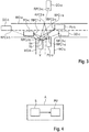
- Figure 4 shows a block diagram of an apparatus A for analyzing reflection signals.
- the apparatus A comprises a sensor S which is adapted to emit and to receive time-dependent reflection signals, wherein each reflection signal corresponds to a respective reflection point candidate.
- the sensor S may comprise a radar sensor and/or an infrared sensor and/or an ultrasonic sensor.
- the apparatus A further comprises a processing unit PU which may comprise at least one microprocessor.
- the processing unit PU is adapted to identify the respective reflection point candidate based on an incoming direction of the received time dependent reflection signal and on a distance determination, for instance based on a time-of-flight analysis.
- the processing unit PU is further adapted to determine time-dependent vectorial distances for first to third reflection signals corresponding to respective first to third reflection point candidates RPC1 to RPC3.
- the distances comprise a first distance d1 between the first and second reflection point candidates RPC1, RPC2, a second distance d2 between the second and third reflection point candidates RPC2, RPC3, a third distance d3 between the first and third reflection point candidates RPC1, RPC3, and first to third sensor distances x1 to x3 between the sensor and the first to third reflection point candidates RPC1 to RPC3, respectively.
- the processing unit PU is further adapted to check if a distance condition and a mirror condition hold.
- the distance condition holds if the time dependence of the absolute value of the first distance d1 is equal to the time dependence of the absolute value of the second distance d2.
- the processing unit PU further determines a time-dependent plane P which is orthogonal to the third distance d3 and extends through the second reflection point candidate RPC2.
- the mirror condition holds if the time dependence of the first distance d1 and the time dependence of the second distance d2 are mirror symmetric relative to the plane P. If the processing unit PU verifies that the distance condition and the mirror condition hold, the processing unit PU is adapted to classify the reflection signal out of the first reflection signal and the third reflection signal RPC1, RPC3, corresponding to the reflection point candidate RPC3 having a larger sensor distance x3 as a false signal.
- the processing unit PU may also be adapted to perform any further method steps as outlined above.
- the processing unit PU may also be adapted to generate a map of reflection points based on the reflection point candidates, wherein reflection point candidates corresponding to false signals are excluded.
- the processing unit may generate an image based on the map of reflection points.
- FIG. 5 shows a block diagram of a driver assistance system DAS according to an embodiment of the invention.
- the driver assistance system DAS comprises an apparatus A according to one of the above embodiments.
- the driver assistance system further comprises a control device CD, which is coupled to the apparatus A and receives the reflection signals together with information about the false reflection signals from the apparatus A.
- the control device D may also only receive those reflection signals which have not been classified as false signals.
- the control device is adapted to control driving functions of the vehicle V based on the reflection signals by taking into account the reflection signals being identified as false signals by the processing unit PU of the apparatus A.
- the control device CD may simply neglect all false signals and may perform driving functions only based on reflection signals not identified as false signals.
- the control device CD may accelerate or decelerate the vehicle based on the reflection signals.
- a vehicle V comprising a driver assistance system DAS is shown, wherein the driver assistance system DAS may be one of the above described embodiments.
- the terms “comprise”, “comprising”, “include”, “including”, “contain”, “containing”, “have”, “having”, and any variations thereof, are intended to be understood in an inclusive (i.e. non-exclusive) sense, such that the process, method, device, apparatus or system described herein is not limited to those features or parts or elements or steps recited but may include other elements, features, parts or steps not expressly listed or inherent to such process, method, article, or apparatus.
- the terms “a” and “an” used herein are intended to be understood as meaning one or more unless explicitly stated otherwise.
- the terms “first”, “third”, “second”, etc. are used merely as labels, and are not intended to impose numerical requirements on or to establish a certain ranking of importance of their objects.
Landscapes
- Engineering & Computer Science (AREA)
- Radar, Positioning & Navigation (AREA)
- Remote Sensing (AREA)
- Physics & Mathematics (AREA)
- Computer Networks & Wireless Communication (AREA)
- General Physics & Mathematics (AREA)
- Electromagnetism (AREA)
- Traffic Control Systems (AREA)
- Optical Radar Systems And Details Thereof (AREA)
- Radar Systems Or Details Thereof (AREA)
Abstract
Description
- The invention relates to method for analyzing reflection signals, an apparatus for analyzing reflection signals, a driver assistance system for a vehicle, and a vehicle. The invention in particular relates to the analysis of reflection signals such as radar signals, infrared signals and/or ultrasonic signals.
- Modern driver assistance systems comprise a plurality of sensors which emit electromagnetic waves, such as radar sensors, infrared sensors or ultrasonic sensors. The reflected electromagnetic waves are received and analyzed in order to determine the distance or exact location of objects within the surrounding of the vehicle. From document
US 2014/0368375 A1 , an exemplary radar sensor is known which is used for a collision detection system in order to avoid collisions with objects in the surrounding of the vehicle. - The electromagnetic waves will not always propagate on a direct path between the object and the sensor. Rather, the electromagnetic wave may be reflected by one or more mirroring surfaces along its path. If the origin of the reflection is guessed based on a time-of-flight analysis in this case, ghost objects are identified, i.e., virtual reflection points which do not correspond to actual physical objects. These false signals or ghost echoes have to be eliminated, because they do not correspond to actual physical entities.
- In view of the above, it is therefore an object of the present invention to provide an analysis of reflection signals which allows eliminating false signals corresponding to ghost echoes.
- In accordance with the invention, a method for analyzing reflection signals with the features as recited in claim 1 is disclosed. Further, an apparatus for analyzing reflection signals having the features of claim 10 is provided. The invention further provides a driver assistance system for a vehicle as recited in claim 14 and a vehicle as recited in claim 15.
- Therefore, according to a first aspect, the invention provides a method for analyzing reflection signals, wherein time-dependent reflection signals are received by a sensor. Each reflection signal corresponds to a respective reflection point candidate. For first to third reflection signals corresponding to respective first to third reflection point candidates, time-dependent vectorial distances are determined, comprising a first distance which extends between the first and second reflection point candidates, a second distance which extends between the second and third reflection point candidates, a third distance which extends between the first and third reflection point candidates, and respective sensor distances which extend between the first or third reflection point candidate and the sensor. It is checked whether the time dependencies of the absolute value of the first distance and the absolute value of the second distance are equal, and if the time dependencies of the first distance and the second distance are mirror symmetric relative to a time dependent plane which is orthogonal to the third distance and extends through the second reflection point candidate. If those conditions hold, i.e., if the result of both checks is positive, the reflection signal out of the first reflection signal and the third reflection signal corresponding to the reflection point candidate having a larger sensor distance is classified as a false signal.
- The invention further provides an apparatus for analyzing reflection signals, comprising a sensor which is adapted to receive time dependent reflection signals, wherein each reflection signal corresponds to a respective reflection point candidate. The apparatus further comprises a processing unit which is adapted to determine, for first to third reflection signals corresponding to respective first to third reflection point candidates, time-dependent vectorial distances, wherein a first distance extends between the first and second reflection point candidates, a second distance extends between the second and third reflection point candidates, a third distance extends between the first and third reflection point candidates, and respective sensor distances extend between the first or third reflection point candidate and the sensor. The processing unit is further adapted to check if the following conditions hold:
- a) the time dependencies of the absolute value of the first distance and the absolute value of the second distance are equal, and
- b) the time dependencies of the first distance and the second distance are mirror symmetric relative to a time dependent plane, which is orthogonal to the third distance and extends through the second reflection point candidate.
- The processing unit is adapted to classify the reflection signal out of the first reflection signal and the third reflection signal corresponding to the reflection point candidate having a larger sensor distance as a false signal, if the conditions a) and b) hold.
- According to another aspect of the invention, a driver assistance system for a vehicle is provided, which comprises an apparatus for analyzing reflection signals, and a control device which is adapted to control driving functions of the vehicle based on the reflection signals.
- Driving functions may include active driving functions, like accelerating or decelerating the vehicle or controlling a steering angle of the vehicle. Driving functions of the vehicle may also include passive functions, like providing image data and displaying the image data on a vehicle display to a driver of the vehicle or controlling actuators of the vehicle based on the reflection signals.
- According to a further aspect, the invention provides a vehicle comprising a driver assistance system.
- A reflection point candidate in the sense of the present invention refers to a hypothetical or physical object or entity which is assumed to reflect a signal emitted by the sensor, wherein a path of the electromagnetic wave or signal emitted by the sensor is assumed to follow a straight path from the sensor to the reflection point candidate, is reflected at the reflection point candidate and returns to the sensor along the same path. In other words, reflection point candidates are identified under the assumption that no mirroring surfaces exist which could alter the path of the signals.
- Preferably, the distances between two reflection point candidates are determined based on the sensor distances between a reflection point candidate and the sensor.
- The invention provides a method which allows discriminating between reflection point candidates which correspond to physical objects, i.e., which actually reflect the signal back to the sensor on a straight path without any further reflections in between, and reflection point candidates which do not correspond to physical objects, but instead refer to ghost objects corresponding to echoes of real objects. Thus, the invention helps to avoid misidentifications of non-existing objects and increases the accuracy.
- According to a further embodiment of the method, the reflection signals are received by a radar sensor and/or an infrared sensor and/or an ultrasonic sensor.
- According to a preferred embodiment of the method, reflection signals classified as false signals are excluded from further processing. For instance, the false signals may be deleted.
- According to a further embodiment of the method, the time-dependent vectorial distances are determined for all pairs of reflection point candidates and between all reflection point candidates and the sensor. Accordingly, a precise spatial relationship between all reflection point candidates is known and the method can be repeated for different choices of reflection signals in order to identify all false reflection signals.
- According to a further embodiment of the method, if conditions a) and b) hold, the second reflection point candidate is classified as a mirror point. A mirror point corresponds to a physical object which can reflect the emitted electromagnetic waves or signals. Possible mirror points can comprise guardrails, other vehicles, road signs or general metallic surfaces.
- According to a further embodiment of the method, determining the time-dependent vectorial distances, checking conditions a) and b), and classifying the false signal is repeated for different first and/or third reflection signal, wherein the reflection signal corresponding to the mirror point remains the second reflection signal. Preferably, also reflection signals corresponding to reflection point candidates close to a mirror point, for example within a predetermined distance to a mirror point, can also be chosen as the second reflection signal with a higher priority because it is likely that the mirror point or regions around the mirror point have also reflected further reflection signals.
- According to a further embodiment of the method, determining the time-dependent vectorial distances, checking conditions a) and b), and classifying the false signal is repeated for a different first and/or second and/or third reflection signals out of the set of reflection signals with those reflection signals already identified as false signals being removed. By ignoring false signals in the following evaluation steps, only reflection signals remain which could in principle correspond to real physical objects. The method is faster as compared to a complete evaluation of all reflection signals.
- According to a further embodiment of the method, determining the time-dependent vectorial distances, checking conditions a) and b), and classifying the false signal is repeated for all possible combinations of first to third reflection signals out of the received reflection signals. In this way, all possible false signals can be identified and only reflection signals corresponding to mirror points or to actual physical objects remain.
- According to a further embodiment of the method, if conditions a) and b) hold, the reflection signal out of the first reflection signal and the third reflection signal corresponding to the reflection point candidate having a smaller sensor distance is classified as a valid signal corresponding to a real reflection point or real physical object. Thus, the method allows determining and discriminating between valid signals, false signals and signals corresponding to mirror points.
- According to a further embodiment of the apparatus, the sensor comprises a radar sensor and/or an infrared sensor and/or an ultrasonic sensor.
- According to another embodiment of the apparatus, the processing unit is adapted to generate a map of reflection points based on the reflection point candidates, wherein reflection point candidates corresponding to false signals are excluded.
- According to another embodiment of the apparatus, the processing unit generates an image based on the map of reflection points.
- For a more complete understanding of the invention and the advantages thereof, exemplary embodiments of the invention are explained in more detail in the following description with reference to the accompanying drawing figures, in which like reference characters designate like parts and in which:
- Fig. 1
- shows a flowchart of a method for analyzing reflection signals according to an embodiment of the invention;
- Fig. 2
- shows a schematic top view on an illustrative road scenario for illustrating the method according to the embodiment;
- Fig. 3
- shows a schematic top view on a further illustrative road scenario for illustrating the method according to the embodiment;
- Fig. 4
- shows a schematic block diagram of an apparatus for analyzing reflection signals according to an embodiment of the invention;
- Fig. 5
- shows a schematic block diagram of a driver assistance system according to an embodiment of the invention; and
- Fig. 6
- shows a vehicle comprising a driver assistance system according to an embodiment of the invention.
- The accompanying drawings are included to provide a further understanding of the present invention and are incorporated in and constitute a part of this specification. The drawings illustrate particular embodiments of the invention and together with the description serve to explain the principles of the invention. Other embodiments of the invention and many of the attendant advantages of the invention will be readily appreciated as they become better understood with reference to the following detailed description.
- It will be appreciated that common and well understood elements that may be useful or necessary in a commercially feasible embodiment are not necessarily depicted in order to facilitate a more abstracted view of the embodiments. The elements of the drawings are not necessarily illustrated to scale relative to each other. It will further be appreciated that certain actions and/or steps in an embodiment of a method may be described or depicted in a particular order of occurrences while those skilled in the art will understand that such specificity with respect to sequence is not actually required. It will also be understood that the terms and expressions used in the present specification have the ordinary meaning as is accorded to such terms and expressions with respect to their corresponding respective areas of inquiry and study, except where specific meanings have otherwise been set forth herein.
- In
Figure 1 , a flowchart is shown which illustrates a method for analyzing reflection signals. - The method is in the following explained with reference to
Figure 2 , which is a top view onto an illustrative road scenario. - In a first step S1, a sensor S of a vehicle V, such as a radar sensor and/or an infrared sensor and/or an ultrasonic sensor emits signals in the form of electromagnetic waves and receives reflection signals. The signals can be emitted and received in predetermined time intervals or in a continuous way. In this way, the reflection signals are time-dependent.
- In the scenario illustrated in
Figure 2 , part of the electromagnetic waves follow a straight and direct first signal path R1 to a first reflection point candidate RPC1 which is a point of a further vehicle within the surrounding of the vehicle V which represents a physical object PO. The signal is reflected back to the sensor S along the same first path R1 and is received as a first reflection signal. - Part of the electromagnetic waves also follow a straight and direct second signal path R2 to a second reflection point candidate RPC2 which is a point of a guardrail which represents a mirror object MO. The signal is reflected back to the sensor S along the same second path R2 and is received as a second reflection signal.
- The electromagnetic waves further follows along a third signal path R3 which comprises the second signal path R2 up to the second reflection point candidate RPC2. However, in this case, the electromagnetic wave is not reflected back to the sensor but reflected towards the first reflection point candidate RPC1. The electromagnetic wave is reflected back from the first reflection point along the third signal path R3 to the sensor S and is received as a third reflection signal.
- The sensor measures incoming directions and a respective time-of-flight of the first to third reflection signals.
- Based on incoming directions and on a distance measurement based on a time-of-flight analysis, first to third reflection point candidates RPC1 to RPC3 are identified. The first and second reflection point candidates RPC1 and RPC2 correspond to the actual reflection points, whereas the third reflection point candidate RPC3 corresponds to a point of an unphysical ghost object GO which is a non-existing mirror image of the physical object PO. The third reflection point candidate RPC3 is identified as the point where the signal is believed to be reflected, since the influence of the mirror object MO is not yet known to the sensor.
- In a second step S2, time-dependent vectorial distances are determined based on incoming directions and time-of-flight information of the reflection signals. The distances may have the form of two-dimensional or three-dimensional vectors. A first sensor distance x1 between the first reflection point candidate RPC1 and the sensor S, a second sensor distance x2 between the second reflection point candidate RPC2 and the sensor S, and a third sensor distance x3 between the third reflection point candidate RPC3 and the sensor S are determined based on a time-of-flight analysis of the first to third reflection signals, respectively. Based on the first to third sensor distances x1 to x3, by a geometric analysis a first distance d1 between the first reflection point candidate RPC1 and the second reflection point candidate RPC2, a second distance d2 between the third reflection point candidate RPC3 and the second reflection point candidate RPC2, and a third distance d3 between the first reflection point candidate RPC1 and the third reflection point candidate RPC3 are determined. The exact location of the reflection point candidates RPC1 to RPC3 and therefore also the distances are time-dependent.
- In a third method step S3, a distance condition and a mirror condition are checked. The distance condition holds if the time dependence of the absolute value of the first distance d1 is equal to the time dependence of the absolute value of the second distance d2. The mirror condition holds if the time dependence of the first distance d1 is mirror symmetric to the time dependence second distance d2 relative to a time-dependent plane P which is orthogonal to the third distance d3 and extends through the second reflection point candidate RPC2. Thus, the plane P is constructed based on the determined third distance and the second reflection point candidate and the time dependence of the vectorial first distance d1 and second distance d2 are checked for mirror symmetry. In particular, a velocity and/or an acceleration of the first and third reflection point candidates RPC1, RPC3 relative to the time dependant plane P can be observed and checked for mirror symmetry.
- In a further method step S4, if both the distance condition and the mirror condition hold, the reflection signal out of the first and third reflection signal corresponding to the reflection point candidate RPC 1, RPC3 having a larger sensor distance x1, x3 is classified as a false signal. In the scenario illustrated in
Figure 2 , the third sensor distance x3 corresponding to the third reflection point candidate RPC3 is identified to be larger than the first sensor distance x1 corresponding to the first reflection point candidate RPC1. Thus, the third reflection signal corresponding to the third reflection point candidate RPC3 is identified as a false signal. - The third reflection point candidate RPC3 may only be classified as a false signal if in addition the condition holds that the third reflection point candidate RPC3, the second reflection point candidate RPC2 and the sensor S lie on the same line, i.e. the third distance d2 and the third sensor distance x3 have the same vectorial direction, although with different absolute values.
- Further, the second reflection point candidate RPC2 may be classified as a mirror point corresponding to a mirroring surface or mirror object. Guardrails, road signs or further vehicles may be identified or classified based on reflection point candidates classified as mirror points.
- The first reflection signal corresponding to the first reflection point candidate RPC1 may be identified as a valid signal corresponding to a real physical reflection point. Physical objects in the neighbouring of the vehicle V, such as further vehicles, guardrails, buildings or road signs may be identified and classified based on valid signals.
- According to a further embodiment, all possible combinations of first to third reflection signals out of the received reflection signals are used in order to classify false signals. Preferably, if a reflection signal is classified as a false signal, it is not used for further analyzing steps.
- Preferably, all reflection signals which have not been classified as false signals are analyzed further in order to determine the distances or properties of objects.
- In
Figure 3 illustrates a top view on a further road scenario. A vehicle V comprises a first sensor Sa and a second sensor Sb, such as radar sensors and/or an infrared sensors and/or an ultrasonic sensors which emit and receive reflection signals. - Sensor paths for two respective measurements for the first sensor Sa and one measurement for the second sensor Sb are illustrated. Based on these measurements, three sets of respective first to third reflection point candidates RPC1-a to RPC3-a, RPC1-b to RPC3-b, and RPC1-c to RPC3-c are determined, corresponding to respective physical objects PO-a, PO-b, PO-c, to ghost objects GO-a, GO-b, GO-c, and to mirror objects MO-a, MO-b, MO-c. False signals are determined and the signals and/or objects are classified based on the method steps as outlined above.
-
Figure 4 shows a block diagram of an apparatus A for analyzing reflection signals. The apparatus A comprises a sensor S which is adapted to emit and to receive time-dependent reflection signals, wherein each reflection signal corresponds to a respective reflection point candidate. The sensor S may comprise a radar sensor and/or an infrared sensor and/or an ultrasonic sensor. - The apparatus A further comprises a processing unit PU which may comprise at least one microprocessor.
- The processing unit PU is adapted to identify the respective reflection point candidate based on an incoming direction of the received time dependent reflection signal and on a distance determination, for instance based on a time-of-flight analysis. The processing unit PU is further adapted to determine time-dependent vectorial distances for first to third reflection signals corresponding to respective first to third reflection point candidates RPC1 to RPC3. The distances comprise a first distance d1 between the first and second reflection point candidates RPC1, RPC2, a second distance d2 between the second and third reflection point candidates RPC2, RPC3, a third distance d3 between the first and third reflection point candidates RPC1, RPC3, and first to third sensor distances x1 to x3 between the sensor and the first to third reflection point candidates RPC1 to RPC3, respectively.
- The processing unit PU is further adapted to check if a distance condition and a mirror condition hold. The distance condition holds if the time dependence of the absolute value of the first distance d1 is equal to the time dependence of the absolute value of the second distance d2.
- The processing unit PU further determines a time-dependent plane P which is orthogonal to the third distance d3 and extends through the second reflection point candidate RPC2. The mirror condition holds if the time dependence of the first distance d1 and the time dependence of the second distance d2 are mirror symmetric relative to the plane P. If the processing unit PU verifies that the distance condition and the mirror condition hold, the processing unit PU is adapted to classify the reflection signal out of the first reflection signal and the third reflection signal RPC1, RPC3, corresponding to the reflection point candidate RPC3 having a larger sensor distance x3 as a false signal. The processing unit PU may also be adapted to perform any further method steps as outlined above.
- The processing unit PU may also be adapted to generate a map of reflection points based on the reflection point candidates, wherein reflection point candidates corresponding to false signals are excluded. The processing unit may generate an image based on the map of reflection points.
-
Figure 5 shows a block diagram of a driver assistance system DAS according to an embodiment of the invention. The driver assistance system DAS comprises an apparatus A according to one of the above embodiments. The driver assistance system further comprises a control device CD, which is coupled to the apparatus A and receives the reflection signals together with information about the false reflection signals from the apparatus A. The control device D may also only receive those reflection signals which have not been classified as false signals. The control device is adapted to control driving functions of the vehicle V based on the reflection signals by taking into account the reflection signals being identified as false signals by the processing unit PU of the apparatus A. For instance, the control device CD may simply neglect all false signals and may perform driving functions only based on reflection signals not identified as false signals. For instance, the control device CD may accelerate or decelerate the vehicle based on the reflection signals. - In
Figure 6 , a vehicle V comprising a driver assistance system DAS is shown, wherein the driver assistance system DAS may be one of the above described embodiments. - Although specific embodiments of the invention have been illustrated and described herein, it will be appreciated by those of ordinary skill in the art that a variety of alternate and/or equivalent implementations exist. It should be appreciated that the exemplary embodiment or exemplary embodiments are only examples, and are not intended to limit the scope, applicability, or configuration in any way. Rather, the foregoing summary and detailed description will provide those skilled in the art with a convenient road map for implementing at least one exemplary embodiment, it being understood that various changes may be made in the function and arrangement of elements described in an exemplary embodiment without departing from the scope as set forth in the appended claims and their legal equivalents. Generally, this application is intended to cover any adaptations or variations of the specific embodiments discussed herein.
- In this document, the terms "comprise", "comprising", "include", "including", "contain", "containing", "have", "having", and any variations thereof, are intended to be understood in an inclusive (i.e. non-exclusive) sense, such that the process, method, device, apparatus or system described herein is not limited to those features or parts or elements or steps recited but may include other elements, features, parts or steps not expressly listed or inherent to such process, method, article, or apparatus. Furthermore, the terms "a" and "an" used herein are intended to be understood as meaning one or more unless explicitly stated otherwise. Moreover, the terms "first", "third", "second", etc. are used merely as labels, and are not intended to impose numerical requirements on or to establish a certain ranking of importance of their objects.
-
- A
- apparatus
- d1
- first distance
- d2
- third distance
- d3
- second distance
- CD
- control device
- DAS
- driver assistance system
- GO
- ghost object
- GO-a to GO-c
- ghost objects
- M
- mirror object
- MO-a to MO-c
- mirror objects
- P
- plane
- PU
- processing unit
- PO
- physical object
- PO-a to PO-c
- physical objects
- R1, R2
- signal paths
- RPC1
- first reflection point candidate
- RPC1-a to RPC1-c
- first reflection point candidates
- RPC2
- second reflection point candidate
- RPC2-a to RPC2-c
- second reflection point candidates
- RPC3
- third reflection point candidate
- RPC3-a to RPC3-c
- third reflection point candidates
- S
- sensor
- Sa
- first sensor
- Sb
- second sensor
- x1
- first sensor distance
- x2
- second sensor distance
- x3
- third sensor distance
- V
- vehicle
Claims (15)
- A method for analyzing reflection signals, comprising the following steps:receiving (S1) time-dependent reflection signals by a sensor (S), wherein each reflection signal corresponds to a respective reflection point candidate (RPC1, RPC2, RPC3) ;determining (S2), for first to third reflection signals corresponding to respective first to third reflection point candidates (RPC1, RPC2, RPC3), time-dependent vectorial distances (d1, d2, d3, x1, x2), wherein a first distance (d1) extends between the first and second reflection point candidates (RPC1, RPC2), a second distance (d2) extends between the second and third reflection point candidates (RPC2, RPC3), a third distance (d3) extends between the first and third reflection point candidates (RPC1, RPC3), and respective sensor distances (x1, x3) extend between the first or third reflection point candidate (RPC1, RPC3) and the sensor (S);checking (S3) if the following conditions hold:a) the time dependencies of the absolute value of the first distance (d1) and the absolute value of the second distance (d2) are equal, andb) the time dependencies of the first distance (d1) and the second distance (d2) are mirror symmetric relative to a time-dependent plane (P) which is orthogonal to the third distance (d3) and extends through the second reflection point candidate (RPC2); andif conditions a) and b) hold, classifying (S4) the reflection signal out of the first reflection signal and the third reflection signal corresponding to the reflection point candidate (RPC3) having a larger sensor distance (x3) as a false signal.
- The method according to claim 1, wherein the reflection signals are received by a radar sensor and/or an infrared sensor and/or an ultrasonic sensor.
- The method according to any of the preceding claims,
wherein reflection signals classified as false signals are excluded from further processing. - The method according to any of the preceding claims,
wherein the time-dependent vectorial distances (d1, d2, d3, x1, x2) are determined for all pairs of reflection point candidates (RPC1, RPC2, RPC3) and between all reflection point candidates (RPC1, RPC2, RPC3) and the sensor (S). - The method according to any of the preceding claims,
wherein, if conditions a) and b) hold, the second reflection point candidate (RPC2) is classified as a mirror point. - The method according to claim 5, wherein determining the time-dependent vectorial distances (d1, d2, d3, x1, x2), checking conditions a) and b), and classifying the false signal is repeated for a different first and/or third reflection signal, wherein the reflection signal corresponding to the mirror point remains the second reflection signal.
- The method according to any of the preceding claims,
wherein determining the time-dependent vectorial distances (d1, d2, d3, x1, x2), checking conditions a) and b), and classifying the false signal is repeated for different first and/or second and/or third reflection signals out of the set of reflection signals with those reflection signals already identified as false signals being removed. - The method according to any of the preceding claims,
wherein determining the time-dependent vectorial distances (d1, d2, d3, x1, x2), checking conditions a) and b), and classifying the false signal is repeated for all possible combinations of first to third reflection signals out of the received reflection signals. - The method according to any of the preceding claims,
wherein, if conditions a) and b) hold, the reflection signal out of the first reflection signal and the third reflection signal corresponding to the reflection point candidate (RPC1) having a smaller sensor distance (x1) is classified as a valid signal corresponding to a real reflection point. - An apparatus (A) for analyzing reflection signals, comprising
a sensor (S) adapted to receive time-dependent reflection signals, wherein each reflection signal corresponds to a respective reflection point candidate (RPC1, RPC2, RPC3); and
a processing unit (PU) which is adapted to determine, for first to third reflection signals corresponding to respective first to third reflection point candidates (RPC1, RPC2, RPC3), time-dependent vectorial distances (d1, d2, d3, x1, x2), wherein a first distance (d1) extends between the first and second reflection point candidates (RPC1, RPC2), a second distance (d2) extends between the second and third reflection point candidates (RPC2, RPC3), a third distance (d3) extends between the first and third reflection point candidates (RPC1, RPC3), and respective sensor distances (x1, x3) extend between the first or third reflection point candidate (RPC1, RPC3) and the sensor (S);
wherein the processing unit (PU) is further adapted to check if the following conditions hold:a) the time dependencies of the absolute value of the first distance (d1) and the absolute value of the second distance (d2) are equal, andb) the time dependencies of the first distance (d1) and the second distance (d2) are mirror symmetric relative to a time-dependent plane (P) which is orthogonal to the third distance (d3) and extends through the second reflection point candidate (RPC2); andwherein the processing unit (PU) is adapted to classify the reflection signal out of the first reflection signal and the third reflection signal corresponding to the reflection point candidate (RPC3) having a larger sensor distance (x3) as a false signal, if conditions a) and b) hold. - The apparatus (A) according to claim 10, wherein the sensor (S) comprises a radar sensor and/or an infrared sensor and/or an ultrasonic sensor.
- The apparatus (A) according to any of claims 10 or 11,
wherein the processing unit (PU) is adapted to generate a map of reflection points based on the reflection point candidates (RPC1, RPC2, RPC3), wherein reflection point candidates (RPC3) corresponding to false signals are excluded. - The apparatus (A) according to claim 12, wherein the processing unit (PU) is adapted to generate an image based on the map of reflection points.
- A driver assistance system (DAS) for a vehicle (V), comprising
an apparatus (A) for analyzing reflection signals according to any of claims 10 to 13; and
a control device (CD) which is adapted to control driving functions of the vehicle (V) based on the reflection signals. - A vehicle (V) comprising a driver assistance system (DAS) according to claim 14.
Priority Applications (1)
| Application Number | Priority Date | Filing Date | Title |
|---|---|---|---|
| EP16465539.1A EP3299841B1 (en) | 2016-09-22 | 2016-09-22 | Method and apparatus for analyzing reflection signals, driver assistance system, and vehicle |
Applications Claiming Priority (1)
| Application Number | Priority Date | Filing Date | Title |
|---|---|---|---|
| EP16465539.1A EP3299841B1 (en) | 2016-09-22 | 2016-09-22 | Method and apparatus for analyzing reflection signals, driver assistance system, and vehicle |
Publications (2)
| Publication Number | Publication Date |
|---|---|
| EP3299841A1 true EP3299841A1 (en) | 2018-03-28 |
| EP3299841B1 EP3299841B1 (en) | 2022-05-04 |
Family
ID=57226939
Family Applications (1)
| Application Number | Title | Priority Date | Filing Date |
|---|---|---|---|
| EP16465539.1A Active EP3299841B1 (en) | 2016-09-22 | 2016-09-22 | Method and apparatus for analyzing reflection signals, driver assistance system, and vehicle |
Country Status (1)
| Country | Link |
|---|---|
| EP (1) | EP3299841B1 (en) |
Cited By (10)
| Publication number | Priority date | Publication date | Assignee | Title |
|---|---|---|---|---|
| WO2020039840A1 (en) * | 2018-08-23 | 2020-02-27 | 日立オートモティブシステムズ株式会社 | Radar processing device |
| WO2020180074A1 (en) * | 2019-03-01 | 2020-09-10 | Samsung Electronics Co., Ltd. | Determining relevant signals using multi-dimensional radar signals |
| WO2020210307A1 (en) * | 2019-04-08 | 2020-10-15 | Continental Automotive Systems, Inc. | Ghost object identification for automobile radar tracking |
| JP2020197506A (en) * | 2019-06-05 | 2020-12-10 | 株式会社Subaru | Object detector for vehicles |
| JP2021012104A (en) * | 2019-07-05 | 2021-02-04 | オムロン株式会社 | Radar device, ghost determination method, and program |
| WO2023072347A1 (en) * | 2021-10-25 | 2023-05-04 | Continental Autonomous Mobility Germany GmbH | Method and system for associating real targets and their mirror targets |
| GB2617865A (en) * | 2022-04-21 | 2023-10-25 | Continental Automotive Systems Srl | Method of marking mirror objects in a cross-traffic scenario |
| EP4372415A1 (en) * | 2022-11-16 | 2024-05-22 | Aptiv Technologies Limited | Radar multipath detector |
| JP2024071623A (en) * | 2019-02-28 | 2024-05-24 | ズークス インコーポレイテッド | Recognizing radar returns using speed and position information. |
| EP4549990A1 (en) * | 2023-10-30 | 2025-05-07 | GM Cruise Holdings LLC | Multipath and false detection mitigation |
Citations (5)
| Publication number | Priority date | Publication date | Assignee | Title |
|---|---|---|---|---|
| DE102004058844A1 (en) * | 2004-12-06 | 2006-06-08 | Daimlerchrysler Ag | Traffic condition detecting method, involves detecting virtual reflection points by looped around radar radiations, where reflection points are included in computation for detection of traffic condition |
| DE102012105582A1 (en) * | 2011-07-01 | 2013-01-03 | Conti Temic Microelectronic Gmbh | Simplified calculation of high-resolution angle estimation of two targets with radar system for motor vehicles |
| US20130321195A1 (en) * | 2012-05-31 | 2013-12-05 | Fujitsu Ten Limited | Radar apparatus and signal processing method |
| US20140368375A1 (en) | 2013-06-13 | 2014-12-18 | Continental Automotive Systems, Inc. | Integration of a radar sensor in a vehicle |
| US20150204972A1 (en) * | 2014-01-21 | 2015-07-23 | Robert Bosch Gmbh | Method for angle estimation and radar sensor for motor vehicles |
-
2016
- 2016-09-22 EP EP16465539.1A patent/EP3299841B1/en active Active
Patent Citations (5)
| Publication number | Priority date | Publication date | Assignee | Title |
|---|---|---|---|---|
| DE102004058844A1 (en) * | 2004-12-06 | 2006-06-08 | Daimlerchrysler Ag | Traffic condition detecting method, involves detecting virtual reflection points by looped around radar radiations, where reflection points are included in computation for detection of traffic condition |
| DE102012105582A1 (en) * | 2011-07-01 | 2013-01-03 | Conti Temic Microelectronic Gmbh | Simplified calculation of high-resolution angle estimation of two targets with radar system for motor vehicles |
| US20130321195A1 (en) * | 2012-05-31 | 2013-12-05 | Fujitsu Ten Limited | Radar apparatus and signal processing method |
| US20140368375A1 (en) | 2013-06-13 | 2014-12-18 | Continental Automotive Systems, Inc. | Integration of a radar sensor in a vehicle |
| US20150204972A1 (en) * | 2014-01-21 | 2015-07-23 | Robert Bosch Gmbh | Method for angle estimation and radar sensor for motor vehicles |
Cited By (16)
| Publication number | Priority date | Publication date | Assignee | Title |
|---|---|---|---|---|
| WO2020039840A1 (en) * | 2018-08-23 | 2020-02-27 | 日立オートモティブシステムズ株式会社 | Radar processing device |
| JPWO2020039840A1 (en) * | 2018-08-23 | 2021-08-26 | 日立Astemo株式会社 | Radar processing device |
| JP2024071623A (en) * | 2019-02-28 | 2024-05-24 | ズークス インコーポレイテッド | Recognizing radar returns using speed and position information. |
| WO2020180074A1 (en) * | 2019-03-01 | 2020-09-10 | Samsung Electronics Co., Ltd. | Determining relevant signals using multi-dimensional radar signals |
| US11555915B2 (en) | 2019-03-01 | 2023-01-17 | Samsung Electronics Co., Ltd. | Determining relevant signals using multi-dimensional radar signals |
| US12066528B2 (en) | 2019-03-01 | 2024-08-20 | Samsung Electronics Co., Ltd. | Determining relevant gesture signals using multi-dimensional radar signals |
| WO2020210307A1 (en) * | 2019-04-08 | 2020-10-15 | Continental Automotive Systems, Inc. | Ghost object identification for automobile radar tracking |
| JP2022526819A (en) * | 2019-04-08 | 2022-05-26 | コンチネンタル オートモーティブ システムズ インコーポレイテッド | Ghost object identification for car radar tracking |
| US12196841B2 (en) | 2019-04-08 | 2025-01-14 | Continental Autonomous Mobility US, LLC | Ghost object identification for automobile radar tracking |
| JP2020197506A (en) * | 2019-06-05 | 2020-12-10 | 株式会社Subaru | Object detector for vehicles |
| JP2021012104A (en) * | 2019-07-05 | 2021-02-04 | オムロン株式会社 | Radar device, ghost determination method, and program |
| JP7331506B2 (en) | 2019-07-05 | 2023-08-23 | オムロン株式会社 | RADAR DEVICE, GHOST DETERMINATION METHOD, AND PROGRAM |
| WO2023072347A1 (en) * | 2021-10-25 | 2023-05-04 | Continental Autonomous Mobility Germany GmbH | Method and system for associating real targets and their mirror targets |
| GB2617865A (en) * | 2022-04-21 | 2023-10-25 | Continental Automotive Systems Srl | Method of marking mirror objects in a cross-traffic scenario |
| EP4372415A1 (en) * | 2022-11-16 | 2024-05-22 | Aptiv Technologies Limited | Radar multipath detector |
| EP4549990A1 (en) * | 2023-10-30 | 2025-05-07 | GM Cruise Holdings LLC | Multipath and false detection mitigation |
Also Published As
| Publication number | Publication date |
|---|---|
| EP3299841B1 (en) | 2022-05-04 |
Similar Documents
| Publication | Publication Date | Title |
|---|---|---|
| EP3299841B1 (en) | Method and apparatus for analyzing reflection signals, driver assistance system, and vehicle | |
| US8095313B1 (en) | Method for determining collision risk for collision avoidance systems | |
| US9488725B2 (en) | Method and device for detecting objects in the surroundings of a vehicle | |
| EP3921670B1 (en) | Ghost object identification for automobile radar tracking | |
| US11158192B2 (en) | Method and system for detecting parking spaces which are suitable for a vehicle | |
| JP6333412B2 (en) | Obstacle detection device | |
| Kim et al. | Occurrence and characteristics of mutual interference between LIDAR scanners | |
| US11164460B2 (en) | System for collision avoidance and method for collision avoidance | |
| CN109583416B (en) | Pseudo lane line identification method and system | |
| CN111615641B (en) | Method and apparatus for detecting critical lateral motion | |
| CN112639811A (en) | Method for evaluating sensor data with extended object recognition | |
| US20220342061A1 (en) | Method and a device for classifying an object, in particular in the surroundings of a motor vehicle | |
| CN105549018A (en) | Object detecting apparatus | |
| US10902728B2 (en) | Blind spot object detection | |
| US20250138149A1 (en) | Multipath and false detection mitigation | |
| JP5163084B2 (en) | Object detection device | |
| US12313725B2 (en) | System and method for radar static-dynamic segmentation | |
| JP2023541696A (en) | Method and device for determining false detection of lidar sensor | |
| JP2009075650A (en) | Collision determination device | |
| Eom et al. | Mutual interference potential and impact of scanning lidar according to the relevant vehicle applications | |
| US20210389445A1 (en) | Combined frequency modulated continuous wave radar detection | |
| CN107003405A (en) | For detecting method, computing device, driver assistance system and motor vehicles that the sensor device of motor vehicles is shielded by object | |
| JP6895581B2 (en) | Devices and methods for recognizing the position of an object | |
| ES2248411T3 (en) | PROCEDURE AND DEVICE FOR ESTIMATING PARAMETERS OF MOVEMENT OF OBJECTIVES. | |
| US12292532B2 (en) | Vehicle radar system and target detection |
Legal Events
| Date | Code | Title | Description |
|---|---|---|---|
| PUAI | Public reference made under article 153(3) epc to a published international application that has entered the european phase |
Free format text: ORIGINAL CODE: 0009012 |
|
| STAA | Information on the status of an ep patent application or granted ep patent |
Free format text: STATUS: THE APPLICATION HAS BEEN PUBLISHED |
|
| AK | Designated contracting states |
Kind code of ref document: A1 Designated state(s): AL AT BE BG CH CY CZ DE DK EE ES FI FR GB GR HR HU IE IS IT LI LT LU LV MC MK MT NL NO PL PT RO RS SE SI SK SM TR |
|
| AX | Request for extension of the european patent |
Extension state: BA ME |
|
| STAA | Information on the status of an ep patent application or granted ep patent |
Free format text: STATUS: REQUEST FOR EXAMINATION WAS MADE |
|
| 17P | Request for examination filed |
Effective date: 20180928 |
|
| RBV | Designated contracting states (corrected) |
Designated state(s): AL AT BE BG CH CY CZ DE DK EE ES FI FR GB GR HR HU IE IS IT LI LT LU LV MC MK MT NL NO PL PT RO RS SE SI SK SM TR |
|
| STAA | Information on the status of an ep patent application or granted ep patent |
Free format text: STATUS: EXAMINATION IS IN PROGRESS |
|
| 17Q | First examination report despatched |
Effective date: 20200508 |
|
| RAP1 | Party data changed (applicant data changed or rights of an application transferred) |
Owner name: CONTINENTAL AUTOMOTIVE GMBH |
|
| GRAP | Despatch of communication of intention to grant a patent |
Free format text: ORIGINAL CODE: EPIDOSNIGR1 |
|
| STAA | Information on the status of an ep patent application or granted ep patent |
Free format text: STATUS: GRANT OF PATENT IS INTENDED |
|
| INTG | Intention to grant announced |
Effective date: 20220110 |
|
| GRAS | Grant fee paid |
Free format text: ORIGINAL CODE: EPIDOSNIGR3 |
|
| GRAA | (expected) grant |
Free format text: ORIGINAL CODE: 0009210 |
|
| STAA | Information on the status of an ep patent application or granted ep patent |
Free format text: STATUS: THE PATENT HAS BEEN GRANTED |
|
| AK | Designated contracting states |
Kind code of ref document: B1 Designated state(s): AL AT BE BG CH CY CZ DE DK EE ES FI FR GB GR HR HU IE IS IT LI LT LU LV MC MK MT NL NO PL PT RO RS SE SI SK SM TR |
|
| REG | Reference to a national code |
Ref country code: GB Ref legal event code: FG4D |
|
| REG | Reference to a national code |
Ref country code: CH Ref legal event code: EP |
|
| REG | Reference to a national code |
Ref country code: AT Ref legal event code: REF Ref document number: 1489631 Country of ref document: AT Kind code of ref document: T Effective date: 20220515 |
|
| REG | Reference to a national code |
Ref country code: IE Ref legal event code: FG4D Ref country code: DE Ref legal event code: R096 Ref document number: 602016071709 Country of ref document: DE |
|
| REG | Reference to a national code |
Ref country code: DE Ref legal event code: R081 Ref document number: 602016071709 Country of ref document: DE Owner name: CONTINENTAL AUTONOMOUS MOBILITY GERMANY GMBH, DE Free format text: FORMER OWNER: CONTINENTAL AUTOMOTIVE GMBH, 30165 HANNOVER, DE Ref country code: DE Ref legal event code: R081 Ref document number: 602016071709 Country of ref document: DE Owner name: AUMOVIO AUTONOMOUS MOBILITY GERMANY GMBH, DE Free format text: FORMER OWNER: CONTINENTAL AUTOMOTIVE GMBH, 30165 HANNOVER, DE |
|
| REG | Reference to a national code |
Ref country code: LT Ref legal event code: MG9D |
|
| REG | Reference to a national code |
Ref country code: NL Ref legal event code: MP Effective date: 20220504 |
|
| REG | Reference to a national code |
Ref country code: AT Ref legal event code: MK05 Ref document number: 1489631 Country of ref document: AT Kind code of ref document: T Effective date: 20220504 |
|
| PG25 | Lapsed in a contracting state [announced via postgrant information from national office to epo] |
Ref country code: SE Free format text: LAPSE BECAUSE OF FAILURE TO SUBMIT A TRANSLATION OF THE DESCRIPTION OR TO PAY THE FEE WITHIN THE PRESCRIBED TIME-LIMIT Effective date: 20220504 Ref country code: PT Free format text: LAPSE BECAUSE OF FAILURE TO SUBMIT A TRANSLATION OF THE DESCRIPTION OR TO PAY THE FEE WITHIN THE PRESCRIBED TIME-LIMIT Effective date: 20220905 Ref country code: NO Free format text: LAPSE BECAUSE OF FAILURE TO SUBMIT A TRANSLATION OF THE DESCRIPTION OR TO PAY THE FEE WITHIN THE PRESCRIBED TIME-LIMIT Effective date: 20220804 Ref country code: NL Free format text: LAPSE BECAUSE OF FAILURE TO SUBMIT A TRANSLATION OF THE DESCRIPTION OR TO PAY THE FEE WITHIN THE PRESCRIBED TIME-LIMIT Effective date: 20220504 Ref country code: LT Free format text: LAPSE BECAUSE OF FAILURE TO SUBMIT A TRANSLATION OF THE DESCRIPTION OR TO PAY THE FEE WITHIN THE PRESCRIBED TIME-LIMIT Effective date: 20220504 Ref country code: HR Free format text: LAPSE BECAUSE OF FAILURE TO SUBMIT A TRANSLATION OF THE DESCRIPTION OR TO PAY THE FEE WITHIN THE PRESCRIBED TIME-LIMIT Effective date: 20220504 Ref country code: GR Free format text: LAPSE BECAUSE OF FAILURE TO SUBMIT A TRANSLATION OF THE DESCRIPTION OR TO PAY THE FEE WITHIN THE PRESCRIBED TIME-LIMIT Effective date: 20220805 Ref country code: FI Free format text: LAPSE BECAUSE OF FAILURE TO SUBMIT A TRANSLATION OF THE DESCRIPTION OR TO PAY THE FEE WITHIN THE PRESCRIBED TIME-LIMIT Effective date: 20220504 Ref country code: ES Free format text: LAPSE BECAUSE OF FAILURE TO SUBMIT A TRANSLATION OF THE DESCRIPTION OR TO PAY THE FEE WITHIN THE PRESCRIBED TIME-LIMIT Effective date: 20220504 Ref country code: BG Free format text: LAPSE BECAUSE OF FAILURE TO SUBMIT A TRANSLATION OF THE DESCRIPTION OR TO PAY THE FEE WITHIN THE PRESCRIBED TIME-LIMIT Effective date: 20220804 Ref country code: AT Free format text: LAPSE BECAUSE OF FAILURE TO SUBMIT A TRANSLATION OF THE DESCRIPTION OR TO PAY THE FEE WITHIN THE PRESCRIBED TIME-LIMIT Effective date: 20220504 |
|
| PG25 | Lapsed in a contracting state [announced via postgrant information from national office to epo] |
Ref country code: RS Free format text: LAPSE BECAUSE OF FAILURE TO SUBMIT A TRANSLATION OF THE DESCRIPTION OR TO PAY THE FEE WITHIN THE PRESCRIBED TIME-LIMIT Effective date: 20220504 Ref country code: PL Free format text: LAPSE BECAUSE OF FAILURE TO SUBMIT A TRANSLATION OF THE DESCRIPTION OR TO PAY THE FEE WITHIN THE PRESCRIBED TIME-LIMIT Effective date: 20220504 Ref country code: LV Free format text: LAPSE BECAUSE OF FAILURE TO SUBMIT A TRANSLATION OF THE DESCRIPTION OR TO PAY THE FEE WITHIN THE PRESCRIBED TIME-LIMIT Effective date: 20220504 Ref country code: IS Free format text: LAPSE BECAUSE OF FAILURE TO SUBMIT A TRANSLATION OF THE DESCRIPTION OR TO PAY THE FEE WITHIN THE PRESCRIBED TIME-LIMIT Effective date: 20220904 |
|
| PG25 | Lapsed in a contracting state [announced via postgrant information from national office to epo] |
Ref country code: SM Free format text: LAPSE BECAUSE OF FAILURE TO SUBMIT A TRANSLATION OF THE DESCRIPTION OR TO PAY THE FEE WITHIN THE PRESCRIBED TIME-LIMIT Effective date: 20220504 Ref country code: SK Free format text: LAPSE BECAUSE OF FAILURE TO SUBMIT A TRANSLATION OF THE DESCRIPTION OR TO PAY THE FEE WITHIN THE PRESCRIBED TIME-LIMIT Effective date: 20220504 Ref country code: RO Free format text: LAPSE BECAUSE OF FAILURE TO SUBMIT A TRANSLATION OF THE DESCRIPTION OR TO PAY THE FEE WITHIN THE PRESCRIBED TIME-LIMIT Effective date: 20220504 Ref country code: EE Free format text: LAPSE BECAUSE OF FAILURE TO SUBMIT A TRANSLATION OF THE DESCRIPTION OR TO PAY THE FEE WITHIN THE PRESCRIBED TIME-LIMIT Effective date: 20220504 Ref country code: DK Free format text: LAPSE BECAUSE OF FAILURE TO SUBMIT A TRANSLATION OF THE DESCRIPTION OR TO PAY THE FEE WITHIN THE PRESCRIBED TIME-LIMIT Effective date: 20220504 Ref country code: CZ Free format text: LAPSE BECAUSE OF FAILURE TO SUBMIT A TRANSLATION OF THE DESCRIPTION OR TO PAY THE FEE WITHIN THE PRESCRIBED TIME-LIMIT Effective date: 20220504 |
|
| REG | Reference to a national code |
Ref country code: DE Ref legal event code: R097 Ref document number: 602016071709 Country of ref document: DE |
|
| PLBE | No opposition filed within time limit |
Free format text: ORIGINAL CODE: 0009261 |
|
| STAA | Information on the status of an ep patent application or granted ep patent |
Free format text: STATUS: NO OPPOSITION FILED WITHIN TIME LIMIT |
|
| PG25 | Lapsed in a contracting state [announced via postgrant information from national office to epo] |
Ref country code: AL Free format text: LAPSE BECAUSE OF FAILURE TO SUBMIT A TRANSLATION OF THE DESCRIPTION OR TO PAY THE FEE WITHIN THE PRESCRIBED TIME-LIMIT Effective date: 20220504 |
|
| 26N | No opposition filed |
Effective date: 20230207 |
|
| PG25 | Lapsed in a contracting state [announced via postgrant information from national office to epo] |
Ref country code: MC Free format text: LAPSE BECAUSE OF FAILURE TO SUBMIT A TRANSLATION OF THE DESCRIPTION OR TO PAY THE FEE WITHIN THE PRESCRIBED TIME-LIMIT Effective date: 20220504 |
|
| REG | Reference to a national code |
Ref country code: CH Ref legal event code: PL |
|
| GBPC | Gb: european patent ceased through non-payment of renewal fee |
Effective date: 20220922 |
|
| REG | Reference to a national code |
Ref country code: BE Ref legal event code: MM Effective date: 20220930 |
|
| PG25 | Lapsed in a contracting state [announced via postgrant information from national office to epo] |
Ref country code: SI Free format text: LAPSE BECAUSE OF FAILURE TO SUBMIT A TRANSLATION OF THE DESCRIPTION OR TO PAY THE FEE WITHIN THE PRESCRIBED TIME-LIMIT Effective date: 20220504 |
|
| PG25 | Lapsed in a contracting state [announced via postgrant information from national office to epo] |
Ref country code: LU Free format text: LAPSE BECAUSE OF NON-PAYMENT OF DUE FEES Effective date: 20220922 |
|
| PG25 | Lapsed in a contracting state [announced via postgrant information from national office to epo] |
Ref country code: LI Free format text: LAPSE BECAUSE OF NON-PAYMENT OF DUE FEES Effective date: 20220930 Ref country code: IE Free format text: LAPSE BECAUSE OF NON-PAYMENT OF DUE FEES Effective date: 20220922 Ref country code: CH Free format text: LAPSE BECAUSE OF NON-PAYMENT OF DUE FEES Effective date: 20220930 |
|
| PG25 | Lapsed in a contracting state [announced via postgrant information from national office to epo] |
Ref country code: BE Free format text: LAPSE BECAUSE OF NON-PAYMENT OF DUE FEES Effective date: 20220930 |
|
| PG25 | Lapsed in a contracting state [announced via postgrant information from national office to epo] |
Ref country code: GB Free format text: LAPSE BECAUSE OF NON-PAYMENT OF DUE FEES Effective date: 20220922 |
|
| PG25 | Lapsed in a contracting state [announced via postgrant information from national office to epo] |
Ref country code: IT Free format text: LAPSE BECAUSE OF FAILURE TO SUBMIT A TRANSLATION OF THE DESCRIPTION OR TO PAY THE FEE WITHIN THE PRESCRIBED TIME-LIMIT Effective date: 20220504 |
|
| PG25 | Lapsed in a contracting state [announced via postgrant information from national office to epo] |
Ref country code: HU Free format text: LAPSE BECAUSE OF FAILURE TO SUBMIT A TRANSLATION OF THE DESCRIPTION OR TO PAY THE FEE WITHIN THE PRESCRIBED TIME-LIMIT; INVALID AB INITIO Effective date: 20160922 |
|
| PG25 | Lapsed in a contracting state [announced via postgrant information from national office to epo] |
Ref country code: CY Free format text: LAPSE BECAUSE OF FAILURE TO SUBMIT A TRANSLATION OF THE DESCRIPTION OR TO PAY THE FEE WITHIN THE PRESCRIBED TIME-LIMIT Effective date: 20220504 |
|
| PG25 | Lapsed in a contracting state [announced via postgrant information from national office to epo] |
Ref country code: MK Free format text: LAPSE BECAUSE OF FAILURE TO SUBMIT A TRANSLATION OF THE DESCRIPTION OR TO PAY THE FEE WITHIN THE PRESCRIBED TIME-LIMIT Effective date: 20220504 |
|
| PG25 | Lapsed in a contracting state [announced via postgrant information from national office to epo] |
Ref country code: TR Free format text: LAPSE BECAUSE OF FAILURE TO SUBMIT A TRANSLATION OF THE DESCRIPTION OR TO PAY THE FEE WITHIN THE PRESCRIBED TIME-LIMIT Effective date: 20220504 |
|
| PG25 | Lapsed in a contracting state [announced via postgrant information from national office to epo] |
Ref country code: MT Free format text: LAPSE BECAUSE OF FAILURE TO SUBMIT A TRANSLATION OF THE DESCRIPTION OR TO PAY THE FEE WITHIN THE PRESCRIBED TIME-LIMIT Effective date: 20220504 |
|
| PG25 | Lapsed in a contracting state [announced via postgrant information from national office to epo] |
Ref country code: BG Free format text: LAPSE BECAUSE OF FAILURE TO SUBMIT A TRANSLATION OF THE DESCRIPTION OR TO PAY THE FEE WITHIN THE PRESCRIBED TIME-LIMIT Effective date: 20220504 |
|
| PG25 | Lapsed in a contracting state [announced via postgrant information from national office to epo] |
Ref country code: BG Free format text: LAPSE BECAUSE OF FAILURE TO SUBMIT A TRANSLATION OF THE DESCRIPTION OR TO PAY THE FEE WITHIN THE PRESCRIBED TIME-LIMIT Effective date: 20220504 |
|
| REG | Reference to a national code |
Ref country code: DE Ref legal event code: R081 Ref document number: 602016071709 Country of ref document: DE Owner name: AUMOVIO AUTONOMOUS MOBILITY GERMANY GMBH, DE Free format text: FORMER OWNER: CONTINENTAL AUTONOMOUS MOBILITY GERMANY GMBH, 85057 INGOLSTADT, DE |
|
| PGFP | Annual fee paid to national office [announced via postgrant information from national office to epo] |
Ref country code: DE Payment date: 20250930 Year of fee payment: 10 |
|
| PGFP | Annual fee paid to national office [announced via postgrant information from national office to epo] |
Ref country code: FR Payment date: 20250922 Year of fee payment: 10 |
|
| REG | Reference to a national code |
Ref country code: DE Ref legal event code: R084 Ref document number: 602016071709 Country of ref document: DE |