EP3299790A1 - Method for adaptively cancelling in real time elastic modes in discrete-time signals - Google Patents
Method for adaptively cancelling in real time elastic modes in discrete-time signals Download PDFInfo
- Publication number
- EP3299790A1 EP3299790A1 EP16382445.1A EP16382445A EP3299790A1 EP 3299790 A1 EP3299790 A1 EP 3299790A1 EP 16382445 A EP16382445 A EP 16382445A EP 3299790 A1 EP3299790 A1 EP 3299790A1
- Authority
- EP
- European Patent Office
- Prior art keywords
- elastic
- discrete
- time
- filter
- sample
- Prior art date
- Legal status (The legal status is an assumption and is not a legal conclusion. Google has not performed a legal analysis and makes no representation as to the accuracy of the status listed.)
- Granted
Links
Images




Classifications
-
- G—PHYSICS
- G01—MEASURING; TESTING
- G01M—TESTING STATIC OR DYNAMIC BALANCE OF MACHINES OR STRUCTURES; TESTING OF STRUCTURES OR APPARATUS, NOT OTHERWISE PROVIDED FOR
- G01M9/00—Aerodynamic testing; Arrangements in or on wind tunnels
- G01M9/06—Measuring arrangements specially adapted for aerodynamic testing
-
- G—PHYSICS
- G01—MEASURING; TESTING
- G01M—TESTING STATIC OR DYNAMIC BALANCE OF MACHINES OR STRUCTURES; TESTING OF STRUCTURES OR APPARATUS, NOT OTHERWISE PROVIDED FOR
- G01M5/00—Investigating the elasticity of structures, e.g. deflection of bridges or air-craft wings
- G01M5/0016—Investigating the elasticity of structures, e.g. deflection of bridges or air-craft wings of aircraft wings or blades
-
- G—PHYSICS
- G01—MEASURING; TESTING
- G01M—TESTING STATIC OR DYNAMIC BALANCE OF MACHINES OR STRUCTURES; TESTING OF STRUCTURES OR APPARATUS, NOT OTHERWISE PROVIDED FOR
- G01M9/00—Aerodynamic testing; Arrangements in or on wind tunnels
- G01M9/08—Aerodynamic models
-
- G—PHYSICS
- G05—CONTROLLING; REGULATING
- G05B—CONTROL OR REGULATING SYSTEMS IN GENERAL; FUNCTIONAL ELEMENTS OF SUCH SYSTEMS; MONITORING OR TESTING ARRANGEMENTS FOR SUCH SYSTEMS OR ELEMENTS
- G05B19/00—Program-control systems
- G05B19/02—Program-control systems electric
- G05B19/04—Program control other than numerical control, i.e. in sequence controllers or logic controllers
- G05B19/05—Programmable logic controllers, e.g. simulating logic interconnections of signals according to ladder diagrams or function charts
- G05B19/054—Input/output
-
- G—PHYSICS
- G06—COMPUTING OR CALCULATING; COUNTING
- G06F—ELECTRIC DIGITAL DATA PROCESSING
- G06F17/00—Digital computing or data processing equipment or methods, specially adapted for specific functions
- G06F17/10—Complex mathematical operations
- G06F17/11—Complex mathematical operations for solving equations, e.g. nonlinear equations, general mathematical optimization problems
-
- B—PERFORMING OPERATIONS; TRANSPORTING
- B64—AIRCRAFT; AVIATION; COSMONAUTICS
- B64C—AEROPLANES; HELICOPTERS
- B64C17/00—Aircraft stabilisation not otherwise provided for
Definitions
- the present invention belongs to the field of aeroservoelastic coupling suppression, and particularly, it belongs to the field of real time adaptive cancellation of elastic modes in discrete-time signals which measure the dynamics of a flexible structure.
- the flexible structure is a structure with elastic variable characteristics, and more particularly, a structure with non-linear aerodynamics.
- Said Control Laws are any law which is function of the measured system dynamics, and which governs the movement of the system control devices or effectors, being said effectors any device intended to modify the movement or displacements of a system.
- the aeroservoelastic coupling suppression is a multidisciplinary technology dealing with the interaction of air vehicle non-stationary aerodynamic forces, the structure dynamics and the flight control system dynamics.
- Several studies have been conducted assessing strategies and methodologies in the design of active flight control algorithms to favorably modify the aeroelastic dynamics of the system, or to simply decouple the rigid and elastic measured dynamics to minimize the adverse effects on the stability margins and handling qualities.
- said flying boom is a flexible slender structure with highly non-linear aerodynamics and elastic characteristics that strongly vary with the flight condition, the operational phase, the telescopic beam length and the fuel flow.
- the first bending mode frequency of the flying boom both in free-air and coupled conditions (during refueling operations), lies in the bandwidth of the rigid control frequencies.
- notch filter for very flexible systems which meet the design requirements are also known.
- extended Kalman filters can be applied to attenuate the elastic components in the feedback signals at the resonant frequencies using the theoretic model of the rigid system.
- a spatial filtering technique that uses a distributed sensors array to cancel the elastic modes components in the feedback signal, assuming the elastic modes shapes are known beforehand. Nevertheless, the number of sensors used in spatial filtering technique is in general greater than twice the number of elastic modes to be suppressed.
- the present invention provides an alternative solution for the aforementioned problems, by a method for adaptively cancelling in real time elastic modes in discrete-time signals which measure the dynamics of a flexible structure according to claim 1, a computer program according to claim 6, a system according to claim 7, and an aircraft according to claim 8.
- a method for adaptively cancelling in real time elastic modes in discrete-time signals which measure the dynamics of a flexible structure according to claim 1, a computer program according to claim 6, a system according to claim 7, and an aircraft according to claim 8.
- preferred embodiments of the invention are defined.
- the invention provides a method for adaptively cancelling in real time N elastic modes in discrete-time signals which measure the dynamics of a flexible structure, the flexible structure having elastic variable characteristics, and the method comprising two main blocks:
- flexible structure will be understood as a structure with fast time-varying geometries and exogenous boundary conditions than can suffer discrete changes. Also, said flexible structure is provided with elastic variable characteristics, and in preferred embodiments with non-linear aerodynamics.
- the discrete-time signals which measure the dynamics of a flexible structure comprise a total number N of elastic modes to be cancelled and, advantageously, said flexible structure comprises only two active measurement sources for cancelling all these elastic modes in the discrete-time signals, i.e. the output measurements signals obtained throughout different sampling operations.
- this method advantageously provides reliable results with only two measurement sources.
- the present method uses the minimum information of the flexible structure for cancelling in real time the N selected elastic modes in the discrete-time signals, i.e. in the output measurement signals.
- step a) of the present method Both the number N of elastic modes and the two active measurement sources are provided by the step a) of the present method. Additionally, the step a) further provides the location vectors l of each active measurement source, depending said location vectors l on the spatial positioning of each measurement source on the flexible structure which elastic modes are to be cancelled in the discrete-time signals, i.e. in the output measurements, and the variation of the elastic characteristics of said flexible structure. Said variations condition the locations of said measurement sources due to the fact that different positions of the measurement sources may affect the output measurements provided by the sources.
- Both active measurement sources are sources which indistinctly provide discrete samples of the measured system dynamics, which comprise the system rigid dynamics, the flexible structure dynamics, and the respective measurement noises and errors. Therefore, the user may decide which of the sources may be denoted as A or B. Results of the present method are indistinctly obtained whichever of the sources is considered to be source A or source B. However, the location of source A may affect the location of source B or vice versa.
- the elastic modes iso-displacement points define the location where measurement source B shall not be placed in order to satisfactorily apply the proposed elastic mode cancellation method in the output measurement signals provided by measurement source A or B.
- the measurement sources are sensors.
- active measurement sources will be understood as measurement sources which provide sampling results during the functioning of the present method. This does not exclude additional measurement sources which may be located in the flexible structure but which are not essential for performing the present method once two active measurement sources work in the flexible structure.
- the present method allows the user to decide, depending on the needs or the functioning of structure, the real time sampling by means of the two measurement sources, thus obtaining two output measurement discrete-time scalar signals as the ones provided in step b).
- output measurement will be understood as a signal, and more particularly a signal provided by any active measurement source arranged on the flexible structure.
- Step c) of the present method provides the elastic natural frequency estimate of each elastic mode to be cancelled, frequency which will be different depending on if the method is applied for the first time or not, i.e. if the method is performing the first sampling.
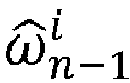
- step c) the method is provided in step c) with a natural frequency estimate ⁇ ⁇ n ⁇ 1 i , which in step c 1 ) is known by the user or by previous results of application of the method, said frequency being ⁇ ⁇ 0 i ; which is understood as the initial natural frequency estimate of the elastic mode i .
- the natural frequency estimate needed is provided as the value inherited from previous samples on which the method has been already performed.
- this allows the method to adjust the results as it is considering the different behavior stages of the flexible structure given an initial estimated value of these frequencies.
- the present method additionally provides a conditioning filter which is a parametric band-pass digital filter that is centered at the frequency estimate of each elastic mode to be cancelled, frequency which is previously provided in step c) of the method.
- said conditioning filter filters the output measurement discrete-time scalar signal, by means of a transfer function, in order to obtain filtered measurement outputs for each elastic mode to be cancelled.
- the conditioning filter of the present method enhances the performance and robustness of the cancelling method comparing with current methods of spatial filtering of the state of the art.
- the elastic natural frequencies are estimated and provided in real time, and the method allows generating a filtered signal which contains only the measured rigid dynamics of the flexible structure, with zero phase-loss and attenuation.
- a second order band-pass digital filter that is centered in the natural frequency estimate of each elastic mode to be cancelled, which was previously provided in step c), is used.
- said second order band-pass digital filter filters the discrete-time scalar signals, which is part of a complementary filter bank, obtaining a filtered discrete-time scalar signal of each elastic modes to be cancelled.
- the second order band-pass digital filter of the present method enhances the performance and robustness of the method comparing with current method of spatial filter.
- the present method additionally comprises the use of a frequency tracking module which in step i) estimates and updates the natural frequency of each elastic mode to be cancelled.
- the adjustment of this natural frequency is performed introducing the estimated mode displacements of each elastic mode in the frequency tracking module, and obtaining the estimated natural frequency updated values.
- the previous updated values are saved in step j).
- steps i) and j) allows the method to be readjusted every time it is ran, therefor the results obtained are more reliable.
- the present method additionally provides a loop in step k) which, advantageously, allows performing step c) to step j), as many times as the number N of elastic modes which are going to be cancelled. Said loop, guarantees that the estimation process is done for every elastic mode to be canceled and also enhances the performance and robustness of the present method.
- the present method additionally provides an elastic mode cancellation output function in step m) which, advantageously, allows the cancellation of each elastic mode to be cancelled in real time in the discrete-time signals which measure the dynamics of the studied flexible structure, taking into consideration the variable conditions and elastic properties of said flexible structure.
- the present method additionally provides an extended spatial filtering.
- said extended spatial filtering is in charge of generating N- 1 virtual signal for complementing the signals measured by the two active measurement sources in order to obtain the elastic mode cancellation output function.
- the present method enhances the performance and robustness compared with methods of spatial filtering known from the state of the art, reducing also the development time and cost associated.
- the conditioning digital filter H c i of step d) of the first inventive aspect is a combination of a narrow band-pass digital filter (BP) centered at ⁇ ⁇ n ⁇ 1 i and one or two narrow stop-band digital filters (SB) centered at ⁇ ⁇ n ⁇ 1 i ⁇ 1 and ⁇ ⁇ n ⁇ 1 i + 1 , and wherein H c i z is the transfer function in the Z-domain of the conditioning digital filter H c i corresponding to the following expression:
- the combination of a band-pass digital filter and one or two narrow digital stop-band filter provides a better adjustment of the natural frequency estimates.
- the narrow band-pass digital filter is defined by a bandwidth ⁇ BP and the one or two narrow stop-band digital filters are defined by a bandwidth ⁇ SB respectively, following the expression:
- the filter width equals the band width of the filter.
- Higher values of band width imply higher filter width values; therefore, the filter can be selected according to the needs.
- the conditioning digital filter H c i of step d) is a combination of a narrow band-pass digital filter (BP) centered at ⁇ ⁇ n ⁇ 1 i and N - 1 narrow stop-band digital filters (SB) centered at ⁇ ⁇ n ⁇ 1 q being q ⁇ N + : ⁇ q ⁇ [1, N ]
- BP narrow
- the combination of a band-pass digital filter and N - 1 narrow digital stop-band filters provides a better adjustment of the natural frequency estimates and a higher cancelation performance of the N elastic modes to be suppressed when the estimated elastic modes frequencies are very close to each other.
- the filter widths equal the band width of the filters. Higher values of band width imply higher filter width values; therefore, the filter can be selected according to the needs.
- the invention provides a computer program comprising computer program code, which, when executed by a computer device, causes the computer device to carry out all the method steps of the first inventive aspect.
- the invention provides a system comprising a flexible structure and N elastic modes to be cancelled in real time in discrete-time signals which measure the dynamics of the flexible structure and a computer device, the computer device being configured to apply a method for adaptively cancelling in real time N elastic modes in said discrete-time signals according to the first inventive aspect.
- the invention provides an aircraft comprising a system according to the third inventive aspect.
- the present invention discloses a method for adaptively cancelling in real time N elastic modes in discrete-time signals which measure the dynamics of a flexible structure, the flexible structure having elastic variable characteristics.
- Elastic mode cancellation in the discrete-time signals which measure the dynamics of a structure can be addressed either theoretically or experimentally.
- N elastic modes estimation kernels are required, wherein each kernel is intended to provide an estimate of the elastic modes displacement, and an estimate of K n i parameter required to cancel a specific elastic mode i, with i ⁇ N + : i ⁇ 1 N , given two output measurement discrete-time scalar signals y A and y B , measured by two measurement sources (A, B) respectively, according to the location of the sources and the characteristics of the structure.
- l A , l B ⁇ R 3 denote the location vectors of the two measurement sources (A, B) respectively,
- the samples y n A and y n B comprise three different components, which are a rigid dynamics component, an elastic component and a noise component directly related with the measurement sources.
- the elastic mode shape of each of the elastic modes fulfills the following condition: ⁇ n i l A ⁇ ⁇ n i l B ,
- an analytical solution can be related with an experimental solution of the parameters, namely the estimated parameters K ⁇ n i .
- K ⁇ n i K n i + ⁇ ⁇ n i ⁇ A i ⁇ B i ⁇ n A ⁇ n B
- ⁇ ⁇ n i is the n th sample of a discrete-time error bias function for elastic mode i which depends on the bandwidth power ratios ⁇ A i and ⁇ B i between the rigid dynamic output measurement r n and the measured elastic displacement of each of the elastic modes i for each active measurement source (A, B) respectively, and also depends on the measurement noises ⁇ n A and ⁇ n B of the active measurement source (A, B).
- the present method provides with a real-time solver which allows the cancellation of said elastic modes according to different changing conditions.
- the present method for cancelling elastic modes in discrete-time signals is divided in two main blocks, wherein different steps are fulfilled in order to obtain a final equation which allows the cancellation of said elastic modes.
- Figure 1 shows a diagram with the steps of the first block for the method to cancel N elastic modes.
- the n th sample y n A and y n B of two output measurement discrete-time scalar signals y A and y B are supplied to the conditioning filter H c i in order to obtain filtered measurement outputs for the elastic mode i , Y A,i and Y B,i .
- the estimated cancellation parameter along with the n th sample y n A will provide of the n th sample y n X of a discrete-time scalar signal y X .
- the method uses a complementary filter bank which performs two different operations.
- the first operation is the filtering of the n th sample of a discrete-time scalar signal, namely y n X , by means of a second order band-pass filter centered in the natural frequency estimate ⁇ ⁇ n ⁇ 1 i of the elastic mode i .
- the second operation is the filtering by means of the former complementary filter of the n th sample y n A . .
- the signal supplied in the mentioned steps is the n th sample y n A as shown in figure 1 .
- the solution of the two filtering steps is used for obtaining a filtered discrete-time scalar signal Y F , being its n th sample namely y n F . .
- This n th sample of the filtered discrete-time scalar signal, y n F along with the n th sample y n A provides with an n th sample of an estimate of the mode displacements for each elastic mode i , ⁇ ⁇ n i . This is shown in figure 1 by means of label "STEP h)".
- the results of the n th sample of an estimate of the mode displacements for each elastic mode i , ⁇ ⁇ n i are used as input to a frequency tracking module, said tracking module consisting on any algorithm that computes the frequency at which a signal has its maximum of power spectral density, for obtaining an adjusted value of ⁇ ⁇ n ⁇ 1 i , namely ⁇ ⁇ n i which will be saved to be used in later steps of the method.
- This is shown in figure 1 by means of a label "STEP i)" and label "STEP j)" respectively.
- Figure 2 shows a diagram with the complete method according to a first embodiment of the present invention.
- the diagram shows how, initiating with the n th sample y n A and y n B of two output measurement discrete-time scalar signals, steps a) and b) of the method, the rest of the steps are fulfilled obtaining the needed results K ⁇ n i and ⁇ ⁇ n i .
- the conditioning filter H c i used in this particular embodiment is a parametric band-pass digital filter centered at the frequency estimate ⁇ ⁇ n ⁇ 1 i of the elastic mode i provided in each of the different steps c) performed for each of the elastic modes i , which can be seen in figure 2 .
- the diagram shows the second block of the method, which ends in the obtainment of Y n output , function which allows the cancellation of the elastic modes components in the discrete-time signals y A and y B .
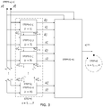
- Figure 3 shows the diagram shown in figure 2 considering a particular composition of the conditioning filter H c i .
- BP narrow band-pass filter
- SB narrow stop-band filter
- step c) is affected every time by the corresponding natural frequencies estimate of the mode i and the modes i - 1, i + 1.
- Figure 4 shows the diagram shown in figures 2 and 3 considering a particular composition of the conditioning filter H c i .
- Said conditioning filter H c i used in this particular embodiment is a combination a narrow band-pass filter (BP) centered at ⁇ ⁇ n ⁇ 1 i and N - 1 narrow stop-band filters (SB) centered at ⁇ ⁇ n ⁇ 1 q being q ⁇ N + : q ⁇ 1 N
- BP narrow band-pass filter
- SB narrow stop-band filters
- step c) is affected every time by the corresponding natural frequencies estimate of the mode i and the modes q being q ⁇ N + : ⁇ q ⁇ [1, N ]
- Figure 5 shows a flying boom of a tanker aircraft (A330 MRTT) comprising two active measurement sources, which are sensor A and sensor B.
- the flying boom comprises elastic modes shapes and undamped elastic modes frequencies which suffer great variations during transitions from free air to coupled condition and vice versa due to the discrete changes in the exogenous boundary conditions acting on the structure.
- the present method can be implemented as part of the Control Laws of any flexible system with more than one sensor located along the structure. Additionally, the present method can be used not only to filter the elastic component in the Control Laws feedback signals, but also to control the elastic dynamics by using a parallel control laws with a feedback composed by the elastic modes displacements identified by the estimation kernels, or simply by using the discrete-time signal y A - Y output and its derivatives as control variables.
Landscapes
- Physics & Mathematics (AREA)
- General Physics & Mathematics (AREA)
- Engineering & Computer Science (AREA)
- Mathematical Physics (AREA)
- Fluid Mechanics (AREA)
- Data Mining & Analysis (AREA)
- Theoretical Computer Science (AREA)
- Computational Mathematics (AREA)
- Mathematical Analysis (AREA)
- Mathematical Optimization (AREA)
- Pure & Applied Mathematics (AREA)
- Aviation & Aerospace Engineering (AREA)
- Operations Research (AREA)
- Algebra (AREA)
- Databases & Information Systems (AREA)
- Software Systems (AREA)
- General Engineering & Computer Science (AREA)
- Automation & Control Theory (AREA)
- Position Fixing By Use Of Radio Waves (AREA)
- Feedback Control In General (AREA)
- Complex Calculations (AREA)
- Vehicle Body Suspensions (AREA)
Abstract
Description
- The present invention belongs to the field of aeroservoelastic coupling suppression, and particularly, it belongs to the field of real time adaptive cancellation of elastic modes in discrete-time signals which measure the dynamics of a flexible structure.
- In particular, the flexible structure is a structure with elastic variable characteristics, and more particularly, a structure with non-linear aerodynamics.
- Along the aerospace history, many are the incidents that have emphasized the important role that aeroservoelastic coupling plays in the stability of controlled vehicles. The instability and handling qualities degradation shall be avoided by suppressing the structural elastic modes (aeroservoelastic coupling suppression) in the feedback paths of the Control Laws.
- Said Control Laws are any law which is function of the measured system dynamics, and which governs the movement of the system control devices or effectors, being said effectors any device intended to modify the movement or displacements of a system.
- The aeroservoelastic coupling suppression is a multidisciplinary technology dealing with the interaction of air vehicle non-stationary aerodynamic forces, the structure dynamics and the flight control system dynamics. Several studies have been conducted assessing strategies and methodologies in the design of active flight control algorithms to favorably modify the aeroelastic dynamics of the system, or to simply decouple the rigid and elastic measured dynamics to minimize the adverse effects on the stability margins and handling qualities.
- In the particular case of controlled systems with a very flexible structure, it is a normal practice to apply filtering techniques as i.e. notch filters for removing the elastic modes from the feedback signals. This known technique is suitable for systems with medium to high elastic modes frequencies, in such a way that said elastic mode frequencies lie outside of the control frequency bandwidth of the augmented system.
- In the particular case of the flying boom installed in a tanker aircraft, said flying boom is a flexible slender structure with highly non-linear aerodynamics and elastic characteristics that strongly vary with the flight condition, the operational phase, the telescopic beam length and the fuel flow. The first bending mode frequency of the flying boom, both in free-air and coupled conditions (during refueling operations), lies in the bandwidth of the rigid control frequencies.
- Alternative solutions to notch filter for very flexible systems which meet the design requirements are also known. For example, extended Kalman filters can be applied to attenuate the elastic components in the feedback signals at the resonant frequencies using the theoretic model of the rigid system. Additionally, it is known a spatial filtering technique that uses a distributed sensors array to cancel the elastic modes components in the feedback signal, assuming the elastic modes shapes are known beforehand. Nevertheless, the number of sensors used in spatial filtering technique is in general greater than twice the number of elastic modes to be suppressed.
- These known alternative solutions, as model-based filtering methods, conventionally lack of robustness and adaptation capabilities against plant uncertainties, cannot cope with fast changes in the structure morphology, and their performance is very sensitive to variations in the exogenous boundary conditions acting on the system. Thus, it is essential to perform an alternative method that minimizes the impact on the sensed rigid dynamics component to fulfill the handling quality level and stability margins requirements; and to achieve a robust online cancellation of the elastic modes in the feedback signals using a non-model-based approach.
- The present invention provides an alternative solution for the aforementioned problems, by a method for adaptively cancelling in real time elastic modes in discrete-time signals which measure the dynamics of a flexible structure according to
claim 1, a computer program according to claim 6, a system according to claim 7, and an aircraft according to claim 8. In dependent claims, preferred embodiments of the invention are defined. - In a first inventive aspect, the invention provides a method for adaptively cancelling in real time N elastic modes in discrete-time signals which measure the dynamics of a flexible structure, the flexible structure having elastic variable characteristics, and the method comprising two main blocks:
- the first block of the method comprising the following steps:
- a) providing a total number


- b) sampling two output measurement discrete-time scalar signals yA and yB of the dynamics of the flexible structure, being


- c) providing natural frequency estimate


- c1) if n = 1; then


- c2) if n ≠ 1; 1; then


- c1) if n = 1; then
- d) filtering the output measurement discrete-time scalar signals yA and yB, by means of a conditioning filter


- e) obtaining an nth sample of an estimated cancellation parameter per elastic mode i to be cancelled,


- f) generating an nth sample of a discrete-time scalar signal yX, namely
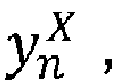

- g) obtaining a filtered discrete-time scalar signal YF by means of the following bank filtering expression in the Z-domain:


obtaining directly from the filtered discrete-time scalar signal YF an nth sample of the filtered discrete-time scalar signal YF , namely YF , - h) obtaining an nth sample of an estimate of the mode displacements for each elastic mode i,

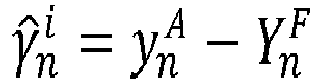
- i) calculating an adjusted value of


- j) saving the adjusted value

- k) performing, from i = 1 to i = N, the steps c) to j),
- a) providing a total number
- the second block of the method comprising the following steps:
- l) inheriting from step h) the values of the nth sample of the estimate of the mode displacements,

- m) obtaining an nth sample of an elastic mode cancellation output function


- m1) calculating the inverse of an estimated spatial filter matrix Φ̂ by the following expression:


- m2) calculating a spatial filter parameter vector


- m3) generating a set of N - 1 parametric discrete-time virtual signals β̂p, being


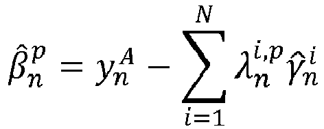
- m4) substituting in the elastic mode cancellation output function


- m1) calculating the inverse of an estimated spatial filter matrix Φ̂ by the following expression:
- n) cancelling the elastic modes i by means of the elastic mode cancellation output function

- o) performing, from n = 1 to n = ∞, the steps b) to n), introducing the saved adjusted

- l) inheriting from step h) the values of the nth sample of the estimate of the mode displacements,
- Throughout this entire document, "adaptively" cancelling elastic modes will be understood as the capability of the method of adjusting the cancelling results when conditions such as the geometry of the flexible structure or the boundary conditions change.
- Throughout this entire document, "flexible" structure will be understood as a structure with fast time-varying geometries and exogenous boundary conditions than can suffer discrete changes. Also, said flexible structure is provided with elastic variable characteristics, and in preferred embodiments with non-linear aerodynamics.
- The discrete-time signals which measure the dynamics of a flexible structure comprise a total number N of elastic modes to be cancelled and, advantageously, said flexible structure comprises only two active measurement sources for cancelling all these elastic modes in the discrete-time signals, i.e. the output measurements signals obtained throughout different sampling operations. Compared with the state of the art, wherein there is need of having at least a number of N + 1 of measurement sources, this method advantageously provides reliable results with only two measurement sources.
- Thus, the present method uses the minimum information of the flexible structure for cancelling in real time the N selected elastic modes in the discrete-time signals, i.e. in the output measurement signals.
- Both the number N of elastic modes and the two active measurement sources are provided by the step a) of the present method. Additionally, the step a) further provides the location vectors l of each active measurement source, depending said location vectors l on the spatial positioning of each measurement source on the flexible structure which elastic modes are to be cancelled in the discrete-time signals, i.e. in the output measurements, and the variation of the elastic characteristics of said flexible structure. Said variations condition the locations of said measurement sources due to the fact that different positions of the measurement sources may affect the output measurements provided by the sources.
- Both active measurement sources, namely sources A and B, are sources which indistinctly provide discrete samples of the measured system dynamics, which comprise the system rigid dynamics, the flexible structure dynamics, and the respective measurement noises and errors. Therefore, the user may decide which of the sources may be denoted as A or B. Results of the present method are indistinctly obtained whichever of the sources is considered to be source A or source B. However, the location of source A may affect the location of source B or vice versa.
- In a preferred embodiment once the location of the measurement source A is selected, the elastic modes iso-displacement points define the location where measurement source B shall not be placed in order to satisfactorily apply the proposed elastic mode cancellation method in the output measurement signals provided by measurement source A or B.
- In a preferred embodiment the measurement sources are sensors.
- Throughout this entire document, "active" measurement sources will be understood as measurement sources which provide sampling results during the functioning of the present method. This does not exclude additional measurement sources which may be located in the flexible structure but which are not essential for performing the present method once two active measurement sources work in the flexible structure.
- Advantageously, the present method allows the user to decide, depending on the needs or the functioning of structure, the real time sampling by means of the two measurement sources, thus obtaining two output measurement discrete-time scalar signals as the ones provided in step b).
- Throughout this entire document, "output measurement" will be understood as a signal, and more particularly a signal provided by any active measurement source arranged on the flexible structure.
- Step c) of the present method provides the elastic natural frequency estimate of each elastic mode to be cancelled, frequency which will be different depending on if the method is applied for the first time or not, i.e. if the method is performing the first sampling.
- Thus, the method is provided in step c) with a natural frequency estimate


- On the contrary, the natural frequency estimate


- That is, the natural frequency estimate needed is provided as the value inherited from previous samples on which the method has been already performed.
- Advantageously, this allows the method to adjust the results as it is considering the different behavior stages of the flexible structure given an initial estimated value of these frequencies.
- The present method additionally provides a conditioning filter which is a parametric band-pass digital filter that is centered at the frequency estimate of each elastic mode to be cancelled, frequency which is previously provided in step c) of the method. Advantageously, said conditioning filter filters the output measurement discrete-time scalar signal, by means of a transfer function, in order to obtain filtered measurement outputs for each elastic mode to be cancelled.
- Additionally, the conditioning filter of the present method enhances the performance and robustness of the cancelling method comparing with current methods of spatial filtering of the state of the art.
- The elastic natural frequencies are estimated and provided in real time, and the method allows generating a filtered signal which contains only the measured rigid dynamics of the flexible structure, with zero phase-loss and attenuation.
- Concerning step g) of the present method, a second order band-pass digital filter that is centered in the natural frequency estimate of each elastic mode to be cancelled, which was previously provided in step c), is used. Advantageously, said second order band-pass digital filter filters the discrete-time scalar signals, which is part of a complementary filter bank, obtaining a filtered discrete-time scalar signal of each elastic modes to be cancelled. Additionally, the second order band-pass digital filter of the present method enhances the performance and robustness of the method comparing with current method of spatial filter.
- The present method additionally comprises the use of a frequency tracking module which in step i) estimates and updates the natural frequency of each elastic mode to be cancelled. The adjustment of this natural frequency is performed introducing the estimated mode displacements of each elastic mode in the frequency tracking module, and obtaining the estimated natural frequency updated values.
- The previous updated values are saved in step j).
- The inclusion of steps i) and j) allows the method to be readjusted every time it is ran, therefor the results obtained are more reliable.
- The present method additionally provides a loop in step k) which, advantageously, allows performing step c) to step j), as many times as the number N of elastic modes which are going to be cancelled. Said loop, guarantees that the estimation process is done for every elastic mode to be canceled and also enhances the performance and robustness of the present method.
- The present method additionally provides an elastic mode cancellation output function in step m) which, advantageously, allows the cancellation of each elastic mode to be cancelled in real time in the discrete-time signals which measure the dynamics of the studied flexible structure, taking into consideration the variable conditions and elastic properties of said flexible structure. For obtaining said output function, the present method additionally provides an extended spatial filtering. Advantageously, said extended spatial filtering is in charge of generating N-1 virtual signal for complementing the signals measured by the two active measurement sources in order to obtain the elastic mode cancellation output function.
- The present method enhances the performance and robustness compared with methods of spatial filtering known from the state of the art, reducing also the development time and cost associated.
- In a particular embodiment, the conditioning digital filter



- if i = 1

- else, if i = 2, ... ,N-1

- else, if i = N


- c1) if n = 1; then

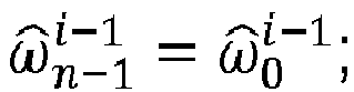


- c2) if n ≠ 1; then


- Advantageously, the combination of a band-pass digital filter and one or two narrow digital stop-band filter provides a better adjustment of the natural frequency estimates.
- In a more particular embodiment, the narrow band-pass digital filter is defined by a bandwidth Δω BP and the one or two narrow stop-band digital filters are defined by a bandwidth Δω SB respectively, following the expression:
- if i = 1

- else, if i = 2,...,N-1

- else, if i = N


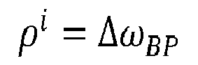

- Advantageously, the filter width equals the band width of the filter. Higher values of band width imply higher filter width values; therefore, the filter can be selected according to the needs.
- In a particular embodiment, the conditioning digital filter


- c1) if n = 1; then
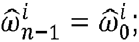




- c2) if n ≠ 1; then


- Advantageously, the combination of a band-pass digital filter and N - 1 narrow digital stop-band filters provides a better adjustment of the natural frequency estimates and a higher cancelation performance of the N elastic modes to be suppressed when the estimated elastic modes frequencies are very close to each other.
- In a more particular embodiment, the narrow band-pass digital filter is defined by a bandwidth Δω BP and the N - 1 narrow stop-band digital filters are defined by a bandwidth Δω SB respectively, following the expression:


- Advantageously, the filter widths equal the band width of the filters. Higher values of band width imply higher filter width values; therefore, the filter can be selected according to the needs.
- In a second inventive aspect, the invention provides a computer program comprising computer program code, which, when executed by a computer device, causes the computer device to carry out all the method steps of the first inventive aspect.
- This allows the performance by means of any computer device of the present elastic mode cancellation method.
- In a third inventive aspect, the invention provides a system comprising a flexible structure and N elastic modes to be cancelled in real time in discrete-time signals which measure the dynamics of the flexible structure and a computer device, the computer device being configured to apply a method for adaptively cancelling in real time N elastic modes in said discrete-time signals according to the first inventive aspect.
- In a fourth inventive aspect, the invention provides an aircraft comprising a system according to the third inventive aspect.
- Advantageously, the performance of this elastic mode cancellation method applied in the discrete-time signals which measure the dynamics of the flexible structure used in the field of aeronautics provides reliable results.
- All the features described in this specification (including the claims, description and drawings) and/or all the steps of the described method can be combined in any combination, with the exception of combinations of such mutually exclusive features and/or steps.
- These and other characteristics and advantages of the invention will become clearly understood in view of the detailed description of the invention which becomes apparent from a preferred embodiment of the invention, given just as an example and not being limited thereto, with reference to the drawings.
- Figure 1
- This figure shows a diagram with the steps of the first block of the method for cancelling elastic modes according to the present invention.
- Figure 2
- This figure shows a diagram with the complete method according to a first embodiment of the present invention.
- Figure 3
- This figure shows a diagram with the complete method according to a second embodiment of the present invention.
- Figure 4
- This figure shows a diagram with the complete method according to a third embodiment of the present invention.
- Figure 5
- This figure shows a particular embodiment of a flying boom of a tanker aircraft on which the elastic mode cancellation method of the present invention is applied to the feedback signals of the Control Laws.
- The present invention discloses a method for adaptively cancelling in real time N elastic modes in discrete-time signals which measure the dynamics of a flexible structure, the flexible structure having elastic variable characteristics. Elastic mode cancellation in the discrete-time signals which measure the dynamics of a structure can be addressed either theoretically or experimentally.
- When considering theoretical studies, there is the need of performing an analytic solving in order to obtain results for the cancellation of the selected elastic modes.
- An example of a theoretical study is disclosed below.
- The theoretical solving is mainly composed by two different steps which are:
- 1) identifying the elastic modes characteristics by a collection of estimation kernels, and
- 2) providing an extended spatial filter algebraic solver.
- Additionally, the theoretical solving estimates, in parallel with said steps, the exogenous boundary condition acting on the system and accordingly configures the constraints applicable to the distributed constrained estimation kernels.
- For cancelling N elastic modes in discrete-time signals which measure the dynamics of a flexible structure with elastic variable characteristics, N elastic modes estimation kernels are required, wherein each kernel is intended to provide an estimate of the elastic modes displacement, and an estimate of


- The nth sample


- n a subscript denoting the nth sample of a discrete-time signal, being n ∈

- i a generic index referring the elastic mode to be cancelled,

- rn is a rigid dynamics output measurement of each active measurement sources (A, B),
-


-

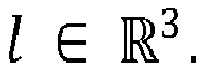
- Therefore, the samples


- The perfect cancellation parameter, as it is theoretically determined,


- Additionally, it is necessary that the elastic mode shape of each of the elastic modes fulfills the following condition:

- According to the previous expressions, the theoretical elastic mode shape cancellation parameter


- These parameters provide the solution of the theoretical function which allows the cancellation of the selected N elastic modes in discrete-time signals which measure the dynamics of the flexible structure.
- Considering said parameters, an analytical solution can be related with an experimental solution of the parameters, namely the estimated parameters

- The relation between the theoretical solution and the experimental solution can be expressed as follows:


- Said bandwidth power ratios


- ω a generic frequency
- ωi a frequency of the elastic mode i
- j a imaginary number equal to

- Δω a generic frequency bandwidth
- Conditions required in the previous equations can be always satisfied if Δω is small enough, considering a small enough value that of Δω < 0.1ωi .
- With these results, a second step is performed considering the actuation of an extended spatial filter algebraic solver, which will finally provide with the output function solution for cancelling the elastic modes using the input discrete-time signals yA and yB.
- However, such a solving for the cancellation of the elastic modes in discrete-time signals is complicated to fulfill, as it is very difficult to distinguish which part of the signals yA and yB comes from the measured rigid dynamics of the system, and which part comes from the measured elastic dynamics of the system. This is why it is not immediate the obtainment of the different components of said signals (rn,


- Therefore, a theoretical solution for the cancelling of elastic modes is complicated to perform. On the contrary, the present method provides with a real-time solver which allows the cancellation of said elastic modes according to different changing conditions.
- The present method for cancelling elastic modes in discrete-time signals is divided in two main blocks, wherein different steps are fulfilled in order to obtain a final equation which allows the cancellation of said elastic modes.
-
Figure 1 shows a diagram with the steps of the first block for the method to cancel N elastic modes. - As it can be observed, the nth sample


- These solutions allow the performance of a least mean square error optimization in order to obtain an nth sample of an estimated cancellation parameter per elastic mode i to be cancelled,

- The obtainment of these parameters is shown in
figure 1 by means of a label "STEP e)". - The estimated cancellation parameter along with the nth sample


- The method uses a complementary filter bank which performs two different operations. The first operation is the filtering of the nth sample of a discrete-time scalar signal, namely


- In this preferred embodiment, the signal supplied in the mentioned steps is the nth sample

figure 1 . - The solution of the two filtering steps is used for obtaining a filtered discrete-time scalar signal YF , being its nth sample namely

- This nth sample of the filtered discrete-time scalar signal,


figure 1 by means of label "STEP h)". - In parallel the results of the nth sample of an estimate of the mode displacements for each elastic mode i,


figure 1 by means of a label "STEP i)" and label "STEP j)" respectively. - The results of these adjusted natural frequency estimates affect the filtering transfer functions, therefore the filters used in the different step of the methods.
-
Figure 2 shows a diagram with the complete method according to a first embodiment of the present invention. - As it can be observed, the totality of the steps of the method are shown in the diagram along with the location of the looping steps which allow the method to readjust considering the changes of the conditions of the elastic system structure.
- The diagram shows how, initiating with the nth sample


- The conditioning filter


figure 2 . - Additionally, the diagram shows the second block of the method, which ends in the obtainment of

-
Figure 3 shows the diagram shown infigure 2 considering a particular composition of the conditioning filter
- Said conditioning filter


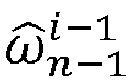


-
Figure 3 shows in each of the different steps c) performed for each of the elastic modes i how the countered-loop from i = 1 to i = N affects the present filter. - As it can be observed, step c) is affected every time by the corresponding natural frequencies estimate of the mode i and the modes i - 1, i + 1.
-
Figure 4 shows the diagram shown infigures 2 and3 considering a particular composition of the conditioning filter
- Said conditioning filter


-
Figure 4 shows in each of the different steps c) performed for each of the elastic modes i how the countered-loop from i = 1 to i = N affects the present filter

-
Figure 5 shows a flying boom of a tanker aircraft (A330 MRTT) comprising two active measurement sources, which are sensor A and sensor B. The flying boom comprises elastic modes shapes and undamped elastic modes frequencies which suffer great variations during transitions from free air to coupled condition and vice versa due to the discrete changes in the exogenous boundary conditions acting on the structure. - For testing the method of the present invention, it has been applied said method on the flying boom Control Laws, obtaining as results the adaptive cancellation in real time of the first two elastic modes in the discrete-time signals which measure the dynamics of the flying boom structure, therefore being the parameter N = 2.
- The present method can be implemented as part of the Control Laws of any flexible system with more than one sensor located along the structure. Additionally, the present method can be used not only to filter the elastic component in the Control Laws feedback signals, but also to control the elastic dynamics by using a parallel control laws with a feedback composed by the elastic modes displacements identified by the estimation kernels, or simply by using the discrete-time signal yA - Youtput and its derivatives as control variables.
Claims (8)
- Method for adaptively cancelling in real time N elastic modes in discrete-time signals which measure the dynamics of a flexible structure, the flexible structure having elastic variable characteristics, and the method comprising two main blocks,:- the first block of the method comprising the following steps:a) providing a total number


 b) sampling two output measurement discrete-time scalar signals yA and yB of the dynamics of the flexible structure, being

 c) providing natural frequency estimate
 c1) if n = 1; then


 c2) if n ≠ 1; then


 d) filtering the output measurement discrete-time scalar signals yA and yB, by means of a conditioning filter


 e) obtaining an nth sample of an estimated cancellation parameter per elastic mode i to be cancelled,
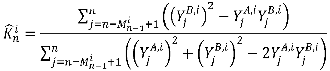
 f) generating an nth sample of a discrete-time scalar signal yx, namely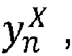
 g) obtaining a filtered discrete-time scalar signal YF by means of the following bank filtering expression in the Z-domain:

obtaining directly from the filtered discrete-time scalar signal YF an nth sample of the filtered discrete-time scalar signal YF , namely h) obtaining an nth sample of an estimate of the mode displacements for each elastic mode i,
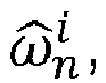
 i) calculating an adjusted value of

 j) saving the adjusted value
 k) performing, from i = 1 to i = N, the steps c) to j),- the second block of the method comprising the following steps:l) inheriting from step h) the values of the nth sample of the estimate of the mode displacements,
 m) obtaining an nth sample of an elastic mode cancellation output function

 m1) calculating the inverse of an estimated spatial filter matrix Φ̂ by the following expression:wherein:


 m2) calculating a spatial filter parameter vector
 m3) generating a set of N - 1 parametric discrete-time virtual signals β̂p, being


 m4) substituting in the elastic mode cancellation output function

 n) cancelling the elastic modes i by means of the elastic mode cancellation output function
 o) performing, from n = 1 to n = ∞, the steps b) to n), introducing the saved adjusted
- Method for adaptively cancelling in real time N elastic modes in discrete-time signals according to claim 1, wherein the conditioning filter


 if i = 1
 else, if i=2,...,N-1
 else, if i = Nand wherein step c) of the method further comprises providing natural frequency estimates

 c1) if n = 1; then


 being
being
 c2) if n ≠ 1; then


- Method for adaptively cancelling in real time N elastic modes in discrete-time signals according to claim 2 wherein the narrow band-pass filter is defined by a bandwidth Δω BP and the one or two narrow stop-band filters are defined by a bandwidth Δω SB respectively, following the expression:if i = 1
 else, if i=2,...,N-1
 else, if i = N



- Method for adaptively cancelling in real time N elastic modes in discrete-time signals according to claim 1, wherein the conditioning filter


 c1) if n = 1; then


 c2) if n ≠ 1; then


- Method for adaptively cancelling in real time N elastic modes in discrete-time signals according to claim 4 wherein the narrow band-pass filter is defined by a bandwidth Δω BP and the N - 1 narrow stop-band filters are defined by a bandwidth Δω SB respectively, following the expression:


- A computer program comprising computer program code, which, when executed by a computer device, causes the computer device to carry out all the method steps of any of the claim 1 to 5.
- System comprising a flexible structure and N elastic modes to be cancelled in real time in discrete-time signals which measure the dynamics of the flexible structure and a computer device, the computer device being configured to apply a method for adaptively cancelling in real time N elastic modes in said discrete-time signals according to any of claims 1 to 5.
- Aircraft comprising a system according to claim 7.
Priority Applications (3)
| Application Number | Priority Date | Filing Date | Title |
|---|---|---|---|
| ES16382445T ES2759401T3 (en) | 2016-09-23 | 2016-09-23 | Method to adaptively cancel in real time elastic modes in discrete signals in time |
| EP16382445.1A EP3299790B1 (en) | 2016-09-23 | 2016-09-23 | Method for adaptively cancelling in real time elastic modes in discrete-time signals |
| US15/713,916 US10514318B2 (en) | 2016-09-23 | 2017-09-25 | Method for adaptively cancelling in real time elastic modes in discrete-time signals |
Applications Claiming Priority (1)
| Application Number | Priority Date | Filing Date | Title |
|---|---|---|---|
| EP16382445.1A EP3299790B1 (en) | 2016-09-23 | 2016-09-23 | Method for adaptively cancelling in real time elastic modes in discrete-time signals |
Publications (2)
| Publication Number | Publication Date |
|---|---|
| EP3299790A1 true EP3299790A1 (en) | 2018-03-28 |
| EP3299790B1 EP3299790B1 (en) | 2019-09-04 |
Family
ID=57209408
Family Applications (1)
| Application Number | Title | Priority Date | Filing Date |
|---|---|---|---|
| EP16382445.1A Active EP3299790B1 (en) | 2016-09-23 | 2016-09-23 | Method for adaptively cancelling in real time elastic modes in discrete-time signals |
Country Status (3)
| Country | Link |
|---|---|
| US (1) | US10514318B2 (en) |
| EP (1) | EP3299790B1 (en) |
| ES (1) | ES2759401T3 (en) |
Cited By (4)
| Publication number | Priority date | Publication date | Assignee | Title |
|---|---|---|---|---|
| CN108009325A (en) * | 2017-11-22 | 2018-05-08 | 中国航空工业集团公司西安飞机设计研究所 | A kind of structure falls into width filter parameter and determines method |
| CN111752213A (en) * | 2019-12-26 | 2020-10-09 | 西安交通大学 | An Electromechanical Coupling Analysis Method Applied to High Speed and High Precision Direct Drive Feeding System |
| EP4060309A1 (en) * | 2021-03-17 | 2022-09-21 | Airbus Defence and Space, S.A.U. | Method for detecting a physical status of a flexible structure |
| CN115270676A (en) * | 2022-07-11 | 2022-11-01 | 宁波天擎航天科技有限公司 | A Design Method of Band Stop Filter |
Families Citing this family (3)
| Publication number | Priority date | Publication date | Assignee | Title |
|---|---|---|---|---|
| CN114398755B (en) * | 2021-12-09 | 2024-04-26 | 航天科工火箭技术有限公司 | Elastic filter design method |
| CN114739237B (en) * | 2022-03-17 | 2024-05-17 | 中国人民解放军63856部队 | Signal bullet information transmission efficiency evaluation system |
| US12503250B2 (en) * | 2023-01-31 | 2025-12-23 | The Boeing Company | Systems and method to determine connection of a boom with a receiver aircraft |
Family Cites Families (9)
| Publication number | Priority date | Publication date | Assignee | Title |
|---|---|---|---|---|
| US4480480A (en) * | 1981-05-18 | 1984-11-06 | Scott Science & Technology, Inc. | System for assessing the integrity of structural systems |
| US6826493B1 (en) * | 2003-09-02 | 2004-11-30 | Tao Of Systems Integration, Inc. | System and method for real time determination of unsteady aerodynamic loads |
| US7307585B2 (en) * | 2005-11-01 | 2007-12-11 | The Boeing Company | Integrated aeroelasticity measurement system |
| DE102006031009B4 (en) * | 2006-07-05 | 2008-07-10 | Airbus Deutschland Gmbh | Method and device for monitoring the status of structural components |
| US7520176B1 (en) * | 2006-12-05 | 2009-04-21 | The United States Of America As Represented By The Administrator Of The National Aeronautics And Space Administration | Method for real-time structure shape-sensing |
| US7715994B1 (en) * | 2008-08-14 | 2010-05-11 | The United States Of America As Represented By The National Aeronautics And Space Administration | Process for using surface strain measurements to obtain operational loads for complex structures |
| DK2659253T3 (en) * | 2010-12-30 | 2018-05-28 | Lm Wind Power Int Tech Ii Aps | METHOD AND APPARATUS FOR DETERMINING LOADS ON A WINDOW MILL |
| US9746392B2 (en) * | 2012-08-07 | 2017-08-29 | The Boeing Company | Systems and methods to determine navigation states of a platform |
| US9073623B1 (en) * | 2013-03-15 | 2015-07-07 | The United States Of America As Represented By The Administrator Of The National Aeronautics And Space Administration | System and method for dynamic aeroelastic control |
-
2016
- 2016-09-23 ES ES16382445T patent/ES2759401T3/en active Active
- 2016-09-23 EP EP16382445.1A patent/EP3299790B1/en active Active
-
2017
- 2017-09-25 US US15/713,916 patent/US10514318B2/en active Active
Non-Patent Citations (2)
| Title |
|---|
| LUM KAI-YEW ET AL: "Reduced-order modeling and flutter suppression control of an experimental wing", 2016 AMERICAN CONTROL CONFERENCE (ACC), AMERICAN AUTOMATIC CONTROL COUNCIL (AACC), 6 July 2016 (2016-07-06), pages 3144 - 3149, XP032933164, DOI: 10.1109/ACC.2016.7525401 * |
| ZHONGJIE MENG ET AL: "Adaptive mode suppression for aeroelastic hypersonic vehicle", INDUSTRIAL ELECTRONICS AND APPLICATIONS (ICIEA), 2011 6TH IEEE CONFERENCE ON, IEEE, 21 June 2011 (2011-06-21), pages 68 - 72, XP032005984, ISBN: 978-1-4244-8754-7, DOI: 10.1109/ICIEA.2011.5975552 * |
Cited By (7)
| Publication number | Priority date | Publication date | Assignee | Title |
|---|---|---|---|---|
| CN108009325A (en) * | 2017-11-22 | 2018-05-08 | 中国航空工业集团公司西安飞机设计研究所 | A kind of structure falls into width filter parameter and determines method |
| CN108009325B (en) * | 2017-11-22 | 2021-09-03 | 中国航空工业集团公司西安飞机设计研究所 | Method for determining parameters of structure notch filter |
| CN111752213A (en) * | 2019-12-26 | 2020-10-09 | 西安交通大学 | An Electromechanical Coupling Analysis Method Applied to High Speed and High Precision Direct Drive Feeding System |
| CN111752213B (en) * | 2019-12-26 | 2021-11-19 | 西安交通大学 | Electromechanical coupling analysis method applied to high-speed high-precision direct-drive feeding system |
| EP4060309A1 (en) * | 2021-03-17 | 2022-09-21 | Airbus Defence and Space, S.A.U. | Method for detecting a physical status of a flexible structure |
| US12091186B2 (en) | 2021-03-17 | 2024-09-17 | Airbus Defence And Space Sau | Method for detecting a physical status of a flexible structure |
| CN115270676A (en) * | 2022-07-11 | 2022-11-01 | 宁波天擎航天科技有限公司 | A Design Method of Band Stop Filter |
Also Published As
| Publication number | Publication date |
|---|---|
| EP3299790B1 (en) | 2019-09-04 |
| ES2759401T3 (en) | 2020-05-08 |
| US20180088000A1 (en) | 2018-03-29 |
| US10514318B2 (en) | 2019-12-24 |
Similar Documents
| Publication | Publication Date | Title |
|---|---|---|
| EP3299790B1 (en) | Method for adaptively cancelling in real time elastic modes in discrete-time signals | |
| US9216830B2 (en) | Method and device for detecting oscillatory failures in a position servocontrol subsystem of an aircraft control surface | |
| Cabell et al. | Experimental feedback control of flow-induced cavity tones | |
| US8849603B2 (en) | Systems and methods for control system verification and health assessment | |
| EP2289800B1 (en) | Method and apparatus for controlling a refueling drogue | |
| US20110119041A1 (en) | Method and device for frequency analysis of data | |
| Karimi et al. | H∞ gain-scheduled controller design for rejection of time-varying narrow-band disturbances applied to a benchmark problem | |
| JP2005513601A (en) | Method for determining control parameters for a control system | |
| EP1814006A1 (en) | Minimizing dynamic structural loads of an aircraft | |
| WO2016133578A2 (en) | Estimating dynamic thrust or shaft power of an engine | |
| CN110231122B (en) | System and computer program product for verifying operation of an air data probe | |
| Yee et al. | High order filter methods for wide range of compressible flow speeds | |
| JP2008257348A (en) | Method for designing controller for vibration reducing device, controller for vibration reducing device, and vibration reducing device | |
| Morelli | Transfer function identification using orthogonal Fourier transform modeling functions | |
| CN118466554B (en) | Photoelectric pod image stabilizing method based on interference moment frequency spectrum and repeated control | |
| US20040267497A1 (en) | Methods and systems for analyzing flutter test data using non-linear transfer function frequency response fitting | |
| De Jesus-Mota et al. | Identification of a MIMO state space model of an F/A-18 aircraft using a subspace method | |
| Hodgkinson | History of low-order equivalent systems for aircraft flying qualities | |
| Kayran | Flight flutter testing and aeroelastic stability of aircraft | |
| Geng et al. | Attitude-control model identification of on-orbit satellites actuated by reaction wheels | |
| Ayadi et al. | Dynamic high-gain observer to estimate pneumatic actuator temperatures | |
| Saussié et al. | Longitudinal flight control synthesis with guardian maps | |
| Catak et al. | Enhanced flight envelope protection: a novel reinforcement learning approach | |
| Grauer et al. | Real-Time Frequency Response Estimation Using Multi-Sine Inputs and Recursive Fourier Transform | |
| CN115982842B (en) | Airspeed estimation method, device, apparatus, and computer-readable storage medium |
Legal Events
| Date | Code | Title | Description |
|---|---|---|---|
| PUAI | Public reference made under article 153(3) epc to a published international application that has entered the european phase |
Free format text: ORIGINAL CODE: 0009012 |
|
| STAA | Information on the status of an ep patent application or granted ep patent |
Free format text: STATUS: THE APPLICATION HAS BEEN PUBLISHED |
|
| AK | Designated contracting states |
Kind code of ref document: A1 Designated state(s): AL AT BE BG CH CY CZ DE DK EE ES FI FR GB GR HR HU IE IS IT LI LT LU LV MC MK MT NL NO PL PT RO RS SE SI SK SM TR |
|
| AX | Request for extension of the european patent |
Extension state: BA ME |
|
| STAA | Information on the status of an ep patent application or granted ep patent |
Free format text: STATUS: REQUEST FOR EXAMINATION WAS MADE |
|
| 17P | Request for examination filed |
Effective date: 20180927 |
|
| RBV | Designated contracting states (corrected) |
Designated state(s): AL AT BE BG CH CY CZ DE DK EE ES FI FR GB GR HR HU IE IS IT LI LT LU LV MC MK MT NL NO PL PT RO RS SE SI SK SM TR |
|
| RIC1 | Information provided on ipc code assigned before grant |
Ipc: G05B 17/00 20060101ALI20190211BHEP Ipc: G01M 5/00 20060101AFI20190211BHEP Ipc: G01M 9/08 20060101ALI20190211BHEP |
|
| GRAP | Despatch of communication of intention to grant a patent |
Free format text: ORIGINAL CODE: EPIDOSNIGR1 |
|
| STAA | Information on the status of an ep patent application or granted ep patent |
Free format text: STATUS: GRANT OF PATENT IS INTENDED |
|
| RIC1 | Information provided on ipc code assigned before grant |
Ipc: G01M 9/08 20060101ALI20190318BHEP Ipc: G01M 5/00 20060101AFI20190318BHEP Ipc: G05B 17/00 20060101ALI20190318BHEP |
|
| INTG | Intention to grant announced |
Effective date: 20190402 |
|
| GRAS | Grant fee paid |
Free format text: ORIGINAL CODE: EPIDOSNIGR3 |
|
| GRAA | (expected) grant |
Free format text: ORIGINAL CODE: 0009210 |
|
| STAA | Information on the status of an ep patent application or granted ep patent |
Free format text: STATUS: THE PATENT HAS BEEN GRANTED |
|
| AK | Designated contracting states |
Kind code of ref document: B1 Designated state(s): AL AT BE BG CH CY CZ DE DK EE ES FI FR GB GR HR HU IE IS IT LI LT LU LV MC MK MT NL NO PL PT RO RS SE SI SK SM TR |
|
| REG | Reference to a national code |
Ref country code: GB Ref legal event code: FG4D |
|
| REG | Reference to a national code |
Ref country code: CH Ref legal event code: EP |
|
| REG | Reference to a national code |
Ref country code: AT Ref legal event code: REF Ref document number: 1176043 Country of ref document: AT Kind code of ref document: T Effective date: 20190915 |
|
| REG | Reference to a national code |
Ref country code: DE Ref legal event code: R096 Ref document number: 602016019835 Country of ref document: DE |
|
| REG | Reference to a national code |
Ref country code: IE Ref legal event code: FG4D |
|
| REG | Reference to a national code |
Ref country code: NL Ref legal event code: MP Effective date: 20190904 |
|
| REG | Reference to a national code |
Ref country code: LT Ref legal event code: MG4D |
|
| PG25 | Lapsed in a contracting state [announced via postgrant information from national office to epo] |
Ref country code: HR Free format text: LAPSE BECAUSE OF FAILURE TO SUBMIT A TRANSLATION OF THE DESCRIPTION OR TO PAY THE FEE WITHIN THE PRESCRIBED TIME-LIMIT Effective date: 20190904 Ref country code: LT Free format text: LAPSE BECAUSE OF FAILURE TO SUBMIT A TRANSLATION OF THE DESCRIPTION OR TO PAY THE FEE WITHIN THE PRESCRIBED TIME-LIMIT Effective date: 20190904 Ref country code: SE Free format text: LAPSE BECAUSE OF FAILURE TO SUBMIT A TRANSLATION OF THE DESCRIPTION OR TO PAY THE FEE WITHIN THE PRESCRIBED TIME-LIMIT Effective date: 20190904 Ref country code: BG Free format text: LAPSE BECAUSE OF FAILURE TO SUBMIT A TRANSLATION OF THE DESCRIPTION OR TO PAY THE FEE WITHIN THE PRESCRIBED TIME-LIMIT Effective date: 20191204 Ref country code: FI Free format text: LAPSE BECAUSE OF FAILURE TO SUBMIT A TRANSLATION OF THE DESCRIPTION OR TO PAY THE FEE WITHIN THE PRESCRIBED TIME-LIMIT Effective date: 20190904 Ref country code: NO Free format text: LAPSE BECAUSE OF FAILURE TO SUBMIT A TRANSLATION OF THE DESCRIPTION OR TO PAY THE FEE WITHIN THE PRESCRIBED TIME-LIMIT Effective date: 20191204 |
|
| PG25 | Lapsed in a contracting state [announced via postgrant information from national office to epo] |
Ref country code: RS Free format text: LAPSE BECAUSE OF FAILURE TO SUBMIT A TRANSLATION OF THE DESCRIPTION OR TO PAY THE FEE WITHIN THE PRESCRIBED TIME-LIMIT Effective date: 20190904 Ref country code: LV Free format text: LAPSE BECAUSE OF FAILURE TO SUBMIT A TRANSLATION OF THE DESCRIPTION OR TO PAY THE FEE WITHIN THE PRESCRIBED TIME-LIMIT Effective date: 20190904 Ref country code: GR Free format text: LAPSE BECAUSE OF FAILURE TO SUBMIT A TRANSLATION OF THE DESCRIPTION OR TO PAY THE FEE WITHIN THE PRESCRIBED TIME-LIMIT Effective date: 20191205 Ref country code: AL Free format text: LAPSE BECAUSE OF FAILURE TO SUBMIT A TRANSLATION OF THE DESCRIPTION OR TO PAY THE FEE WITHIN THE PRESCRIBED TIME-LIMIT Effective date: 20190904 |
|
| REG | Reference to a national code |
Ref country code: AT Ref legal event code: MK05 Ref document number: 1176043 Country of ref document: AT Kind code of ref document: T Effective date: 20190904 |
|
| PG25 | Lapsed in a contracting state [announced via postgrant information from national office to epo] |
Ref country code: NL Free format text: LAPSE BECAUSE OF FAILURE TO SUBMIT A TRANSLATION OF THE DESCRIPTION OR TO PAY THE FEE WITHIN THE PRESCRIBED TIME-LIMIT Effective date: 20190904 Ref country code: AT Free format text: LAPSE BECAUSE OF FAILURE TO SUBMIT A TRANSLATION OF THE DESCRIPTION OR TO PAY THE FEE WITHIN THE PRESCRIBED TIME-LIMIT Effective date: 20190904 Ref country code: EE Free format text: LAPSE BECAUSE OF FAILURE TO SUBMIT A TRANSLATION OF THE DESCRIPTION OR TO PAY THE FEE WITHIN THE PRESCRIBED TIME-LIMIT Effective date: 20190904 Ref country code: IT Free format text: LAPSE BECAUSE OF FAILURE TO SUBMIT A TRANSLATION OF THE DESCRIPTION OR TO PAY THE FEE WITHIN THE PRESCRIBED TIME-LIMIT Effective date: 20190904 Ref country code: RO Free format text: LAPSE BECAUSE OF FAILURE TO SUBMIT A TRANSLATION OF THE DESCRIPTION OR TO PAY THE FEE WITHIN THE PRESCRIBED TIME-LIMIT Effective date: 20190904 Ref country code: PT Free format text: LAPSE BECAUSE OF FAILURE TO SUBMIT A TRANSLATION OF THE DESCRIPTION OR TO PAY THE FEE WITHIN THE PRESCRIBED TIME-LIMIT Effective date: 20200106 Ref country code: PL Free format text: LAPSE BECAUSE OF FAILURE TO SUBMIT A TRANSLATION OF THE DESCRIPTION OR TO PAY THE FEE WITHIN THE PRESCRIBED TIME-LIMIT Effective date: 20190904 |
|
| REG | Reference to a national code |
Ref country code: ES Ref legal event code: FG2A Ref document number: 2759401 Country of ref document: ES Kind code of ref document: T3 Effective date: 20200508 |
|
| PG25 | Lapsed in a contracting state [announced via postgrant information from national office to epo] |
Ref country code: SM Free format text: LAPSE BECAUSE OF FAILURE TO SUBMIT A TRANSLATION OF THE DESCRIPTION OR TO PAY THE FEE WITHIN THE PRESCRIBED TIME-LIMIT Effective date: 20190904 Ref country code: IS Free format text: LAPSE BECAUSE OF FAILURE TO SUBMIT A TRANSLATION OF THE DESCRIPTION OR TO PAY THE FEE WITHIN THE PRESCRIBED TIME-LIMIT Effective date: 20200224 Ref country code: SK Free format text: LAPSE BECAUSE OF FAILURE TO SUBMIT A TRANSLATION OF THE DESCRIPTION OR TO PAY THE FEE WITHIN THE PRESCRIBED TIME-LIMIT Effective date: 20190904 Ref country code: CZ Free format text: LAPSE BECAUSE OF FAILURE TO SUBMIT A TRANSLATION OF THE DESCRIPTION OR TO PAY THE FEE WITHIN THE PRESCRIBED TIME-LIMIT Effective date: 20190904 |
|
| REG | Reference to a national code |
Ref country code: CH Ref legal event code: PL |
|
| REG | Reference to a national code |
Ref country code: DE Ref legal event code: R097 Ref document number: 602016019835 Country of ref document: DE |
|
| PLBE | No opposition filed within time limit |
Free format text: ORIGINAL CODE: 0009261 |
|
| STAA | Information on the status of an ep patent application or granted ep patent |
Free format text: STATUS: NO OPPOSITION FILED WITHIN TIME LIMIT |
|
| PG2D | Information on lapse in contracting state deleted |
Ref country code: IS |
|
| PG25 | Lapsed in a contracting state [announced via postgrant information from national office to epo] |
Ref country code: LU Free format text: LAPSE BECAUSE OF NON-PAYMENT OF DUE FEES Effective date: 20190923 Ref country code: DK Free format text: LAPSE BECAUSE OF FAILURE TO SUBMIT A TRANSLATION OF THE DESCRIPTION OR TO PAY THE FEE WITHIN THE PRESCRIBED TIME-LIMIT Effective date: 20190904 Ref country code: CH Free format text: LAPSE BECAUSE OF NON-PAYMENT OF DUE FEES Effective date: 20190930 Ref country code: LI Free format text: LAPSE BECAUSE OF NON-PAYMENT OF DUE FEES Effective date: 20190930 Ref country code: IE Free format text: LAPSE BECAUSE OF NON-PAYMENT OF DUE FEES Effective date: 20190923 Ref country code: IS Free format text: LAPSE BECAUSE OF FAILURE TO SUBMIT A TRANSLATION OF THE DESCRIPTION OR TO PAY THE FEE WITHIN THE PRESCRIBED TIME-LIMIT Effective date: 20200105 |
|
| REG | Reference to a national code |
Ref country code: BE Ref legal event code: MM Effective date: 20190930 |
|
| 26N | No opposition filed |
Effective date: 20200605 |
|
| PG25 | Lapsed in a contracting state [announced via postgrant information from national office to epo] |
Ref country code: SI Free format text: LAPSE BECAUSE OF FAILURE TO SUBMIT A TRANSLATION OF THE DESCRIPTION OR TO PAY THE FEE WITHIN THE PRESCRIBED TIME-LIMIT Effective date: 20190904 Ref country code: BE Free format text: LAPSE BECAUSE OF NON-PAYMENT OF DUE FEES Effective date: 20190930 Ref country code: MC Free format text: LAPSE BECAUSE OF FAILURE TO SUBMIT A TRANSLATION OF THE DESCRIPTION OR TO PAY THE FEE WITHIN THE PRESCRIBED TIME-LIMIT Effective date: 20190904 |
|
| PG25 | Lapsed in a contracting state [announced via postgrant information from national office to epo] |
Ref country code: CY Free format text: LAPSE BECAUSE OF FAILURE TO SUBMIT A TRANSLATION OF THE DESCRIPTION OR TO PAY THE FEE WITHIN THE PRESCRIBED TIME-LIMIT Effective date: 20190904 |
|
| PG25 | Lapsed in a contracting state [announced via postgrant information from national office to epo] |
Ref country code: HU Free format text: LAPSE BECAUSE OF FAILURE TO SUBMIT A TRANSLATION OF THE DESCRIPTION OR TO PAY THE FEE WITHIN THE PRESCRIBED TIME-LIMIT; INVALID AB INITIO Effective date: 20160923 Ref country code: MT Free format text: LAPSE BECAUSE OF FAILURE TO SUBMIT A TRANSLATION OF THE DESCRIPTION OR TO PAY THE FEE WITHIN THE PRESCRIBED TIME-LIMIT Effective date: 20190904 |
|
| PG25 | Lapsed in a contracting state [announced via postgrant information from national office to epo] |
Ref country code: TR Free format text: LAPSE BECAUSE OF FAILURE TO SUBMIT A TRANSLATION OF THE DESCRIPTION OR TO PAY THE FEE WITHIN THE PRESCRIBED TIME-LIMIT Effective date: 20190904 |
|
| PG25 | Lapsed in a contracting state [announced via postgrant information from national office to epo] |
Ref country code: MK Free format text: LAPSE BECAUSE OF FAILURE TO SUBMIT A TRANSLATION OF THE DESCRIPTION OR TO PAY THE FEE WITHIN THE PRESCRIBED TIME-LIMIT Effective date: 20190904 |
|
| PGFP | Annual fee paid to national office [announced via postgrant information from national office to epo] |
Ref country code: DE Payment date: 20250919 Year of fee payment: 10 |
|
| PGFP | Annual fee paid to national office [announced via postgrant information from national office to epo] |
Ref country code: GB Payment date: 20250919 Year of fee payment: 10 |
|
| PGFP | Annual fee paid to national office [announced via postgrant information from national office to epo] |
Ref country code: FR Payment date: 20250922 Year of fee payment: 10 |
|
| PGFP | Annual fee paid to national office [announced via postgrant information from national office to epo] |
Ref country code: ES Payment date: 20251028 Year of fee payment: 10 |