EP3299751B1 - Blower and refrigerator having the same - Google Patents
Blower and refrigerator having the same Download PDFInfo
- Publication number
- EP3299751B1 EP3299751B1 EP17192759.3A EP17192759A EP3299751B1 EP 3299751 B1 EP3299751 B1 EP 3299751B1 EP 17192759 A EP17192759 A EP 17192759A EP 3299751 B1 EP3299751 B1 EP 3299751B1
- Authority
- EP
- European Patent Office
- Prior art keywords
- water repellent
- interference prevention
- cold air
- base plate
- prevention portion
- Prior art date
- Legal status (The legal status is an assumption and is not a legal conclusion. Google has not performed a legal analysis and makes no representation as to the accuracy of the status listed.)
- Active
Links
Images








Classifications
-
- F—MECHANICAL ENGINEERING; LIGHTING; HEATING; WEAPONS; BLASTING
- F25—REFRIGERATION OR COOLING; COMBINED HEATING AND REFRIGERATION SYSTEMS; HEAT PUMP SYSTEMS; MANUFACTURE OR STORAGE OF ICE; LIQUEFACTION SOLIDIFICATION OF GASES
- F25D—REFRIGERATORS; COLD ROOMS; ICE-BOXES; COOLING OR FREEZING APPARATUS NOT OTHERWISE PROVIDED FOR
- F25D17/00—Arrangements for circulating cooling fluids; Arrangements for circulating gas, e.g. air, within refrigerated spaces
- F25D17/04—Arrangements for circulating cooling fluids; Arrangements for circulating gas, e.g. air, within refrigerated spaces for circulating air, e.g. by convection
- F25D17/042—Air treating means within refrigerated spaces
- F25D17/045—Air flow control arrangements
-
- F—MECHANICAL ENGINEERING; LIGHTING; HEATING; WEAPONS; BLASTING
- F04—POSITIVE - DISPLACEMENT MACHINES FOR LIQUIDS; PUMPS FOR LIQUIDS OR ELASTIC FLUIDS
- F04D—NON-POSITIVE-DISPLACEMENT PUMPS
- F04D19/00—Axial-flow pumps
- F04D19/002—Axial flow fans
-
- F—MECHANICAL ENGINEERING; LIGHTING; HEATING; WEAPONS; BLASTING
- F04—POSITIVE - DISPLACEMENT MACHINES FOR LIQUIDS; PUMPS FOR LIQUIDS OR ELASTIC FLUIDS
- F04D—NON-POSITIVE-DISPLACEMENT PUMPS
- F04D25/00—Pumping installations or systems
- F04D25/02—Units comprising pumps and their driving means
- F04D25/08—Units comprising pumps and their driving means the working fluid being air, e.g. for ventilation
-
- F—MECHANICAL ENGINEERING; LIGHTING; HEATING; WEAPONS; BLASTING
- F04—POSITIVE - DISPLACEMENT MACHINES FOR LIQUIDS; PUMPS FOR LIQUIDS OR ELASTIC FLUIDS
- F04D—NON-POSITIVE-DISPLACEMENT PUMPS
- F04D29/00—Details, component parts, or accessories
- F04D29/08—Sealings
- F04D29/16—Sealings between pressure and suction sides
- F04D29/161—Sealings between pressure and suction sides especially adapted for elastic fluid pumps
- F04D29/164—Sealings between pressure and suction sides especially adapted for elastic fluid pumps of an axial flow wheel
-
- F—MECHANICAL ENGINEERING; LIGHTING; HEATING; WEAPONS; BLASTING
- F04—POSITIVE - DISPLACEMENT MACHINES FOR LIQUIDS; PUMPS FOR LIQUIDS OR ELASTIC FLUIDS
- F04D—NON-POSITIVE-DISPLACEMENT PUMPS
- F04D29/00—Details, component parts, or accessories
- F04D29/26—Rotors specially for elastic fluids
- F04D29/32—Rotors specially for elastic fluids for axial flow pumps
- F04D29/38—Blades
- F04D29/388—Blades characterised by construction
-
- F—MECHANICAL ENGINEERING; LIGHTING; HEATING; WEAPONS; BLASTING
- F04—POSITIVE - DISPLACEMENT MACHINES FOR LIQUIDS; PUMPS FOR LIQUIDS OR ELASTIC FLUIDS
- F04D—NON-POSITIVE-DISPLACEMENT PUMPS
- F04D29/00—Details, component parts, or accessories
- F04D29/40—Casings; Connections of working fluid
- F04D29/52—Casings; Connections of working fluid for axial pumps
- F04D29/522—Casings; Connections of working fluid for axial pumps especially adapted for elastic fluid pumps
-
- F—MECHANICAL ENGINEERING; LIGHTING; HEATING; WEAPONS; BLASTING
- F04—POSITIVE - DISPLACEMENT MACHINES FOR LIQUIDS; PUMPS FOR LIQUIDS OR ELASTIC FLUIDS
- F04D—NON-POSITIVE-DISPLACEMENT PUMPS
- F04D29/00—Details, component parts, or accessories
- F04D29/60—Mounting; Assembling; Disassembling
- F04D29/601—Mounting; Assembling; Disassembling specially adapted for elastic fluid pumps
-
- F—MECHANICAL ENGINEERING; LIGHTING; HEATING; WEAPONS; BLASTING
- F04—POSITIVE - DISPLACEMENT MACHINES FOR LIQUIDS; PUMPS FOR LIQUIDS OR ELASTIC FLUIDS
- F04D—NON-POSITIVE-DISPLACEMENT PUMPS
- F04D29/00—Details, component parts, or accessories
- F04D29/70—Suction grids; Strainers; Dust separation; Cleaning
-
- F—MECHANICAL ENGINEERING; LIGHTING; HEATING; WEAPONS; BLASTING
- F25—REFRIGERATION OR COOLING; COMBINED HEATING AND REFRIGERATION SYSTEMS; HEAT PUMP SYSTEMS; MANUFACTURE OR STORAGE OF ICE; LIQUEFACTION SOLIDIFICATION OF GASES
- F25D—REFRIGERATORS; COLD ROOMS; ICE-BOXES; COOLING OR FREEZING APPARATUS NOT OTHERWISE PROVIDED FOR
- F25D17/00—Arrangements for circulating cooling fluids; Arrangements for circulating gas, e.g. air, within refrigerated spaces
- F25D17/04—Arrangements for circulating cooling fluids; Arrangements for circulating gas, e.g. air, within refrigerated spaces for circulating air, e.g. by convection
- F25D17/06—Arrangements for circulating cooling fluids; Arrangements for circulating gas, e.g. air, within refrigerated spaces for circulating air, e.g. by convection by forced circulation
- F25D17/062—Arrangements for circulating cooling fluids; Arrangements for circulating gas, e.g. air, within refrigerated spaces for circulating air, e.g. by convection by forced circulation in household refrigerators
-
- F—MECHANICAL ENGINEERING; LIGHTING; HEATING; WEAPONS; BLASTING
- F25—REFRIGERATION OR COOLING; COMBINED HEATING AND REFRIGERATION SYSTEMS; HEAT PUMP SYSTEMS; MANUFACTURE OR STORAGE OF ICE; LIQUEFACTION SOLIDIFICATION OF GASES
- F25D—REFRIGERATORS; COLD ROOMS; ICE-BOXES; COOLING OR FREEZING APPARATUS NOT OTHERWISE PROVIDED FOR
- F25D17/00—Arrangements for circulating cooling fluids; Arrangements for circulating gas, e.g. air, within refrigerated spaces
- F25D17/04—Arrangements for circulating cooling fluids; Arrangements for circulating gas, e.g. air, within refrigerated spaces for circulating air, e.g. by convection
- F25D17/06—Arrangements for circulating cooling fluids; Arrangements for circulating gas, e.g. air, within refrigerated spaces for circulating air, e.g. by convection by forced circulation
- F25D17/062—Arrangements for circulating cooling fluids; Arrangements for circulating gas, e.g. air, within refrigerated spaces for circulating air, e.g. by convection by forced circulation in household refrigerators
- F25D17/065—Arrangements for circulating cooling fluids; Arrangements for circulating gas, e.g. air, within refrigerated spaces for circulating air, e.g. by convection by forced circulation in household refrigerators with compartments at different temperatures
-
- F—MECHANICAL ENGINEERING; LIGHTING; HEATING; WEAPONS; BLASTING
- F25—REFRIGERATION OR COOLING; COMBINED HEATING AND REFRIGERATION SYSTEMS; HEAT PUMP SYSTEMS; MANUFACTURE OR STORAGE OF ICE; LIQUEFACTION SOLIDIFICATION OF GASES
- F25D—REFRIGERATORS; COLD ROOMS; ICE-BOXES; COOLING OR FREEZING APPARATUS NOT OTHERWISE PROVIDED FOR
- F25D17/00—Arrangements for circulating cooling fluids; Arrangements for circulating gas, e.g. air, within refrigerated spaces
- F25D17/04—Arrangements for circulating cooling fluids; Arrangements for circulating gas, e.g. air, within refrigerated spaces for circulating air, e.g. by convection
- F25D17/06—Arrangements for circulating cooling fluids; Arrangements for circulating gas, e.g. air, within refrigerated spaces for circulating air, e.g. by convection by forced circulation
- F25D17/08—Arrangements for circulating cooling fluids; Arrangements for circulating gas, e.g. air, within refrigerated spaces for circulating air, e.g. by convection by forced circulation using ducts
-
- F—MECHANICAL ENGINEERING; LIGHTING; HEATING; WEAPONS; BLASTING
- F25—REFRIGERATION OR COOLING; COMBINED HEATING AND REFRIGERATION SYSTEMS; HEAT PUMP SYSTEMS; MANUFACTURE OR STORAGE OF ICE; LIQUEFACTION SOLIDIFICATION OF GASES
- F25D—REFRIGERATORS; COLD ROOMS; ICE-BOXES; COOLING OR FREEZING APPARATUS NOT OTHERWISE PROVIDED FOR
- F25D21/00—Defrosting; Preventing frosting; Removing condensed or defrost water
- F25D21/04—Preventing the formation of frost or condensate
-
- F—MECHANICAL ENGINEERING; LIGHTING; HEATING; WEAPONS; BLASTING
- F25—REFRIGERATION OR COOLING; COMBINED HEATING AND REFRIGERATION SYSTEMS; HEAT PUMP SYSTEMS; MANUFACTURE OR STORAGE OF ICE; LIQUEFACTION SOLIDIFICATION OF GASES
- F25D—REFRIGERATORS; COLD ROOMS; ICE-BOXES; COOLING OR FREEZING APPARATUS NOT OTHERWISE PROVIDED FOR
- F25D21/00—Defrosting; Preventing frosting; Removing condensed or defrost water
- F25D21/14—Collecting or removing condensed and defrost water; Drip trays
-
- F—MECHANICAL ENGINEERING; LIGHTING; HEATING; WEAPONS; BLASTING
- F05—INDEXING SCHEMES RELATING TO ENGINES OR PUMPS IN VARIOUS SUBCLASSES OF CLASSES F01-F04
- F05D—INDEXING SCHEME FOR ASPECTS RELATING TO NON-POSITIVE-DISPLACEMENT MACHINES OR ENGINES, GAS-TURBINES OR JET-PROPULSION PLANTS
- F05D2300/00—Materials; Properties thereof
- F05D2300/60—Properties or characteristics given to material by treatment or manufacturing
- F05D2300/611—Coating
-
- F—MECHANICAL ENGINEERING; LIGHTING; HEATING; WEAPONS; BLASTING
- F25—REFRIGERATION OR COOLING; COMBINED HEATING AND REFRIGERATION SYSTEMS; HEAT PUMP SYSTEMS; MANUFACTURE OR STORAGE OF ICE; LIQUEFACTION SOLIDIFICATION OF GASES
- F25D—REFRIGERATORS; COLD ROOMS; ICE-BOXES; COOLING OR FREEZING APPARATUS NOT OTHERWISE PROVIDED FOR
- F25D11/00—Self-contained movable devices, e.g. domestic refrigerators
- F25D11/02—Self-contained movable devices, e.g. domestic refrigerators with cooling compartments at different temperatures
-
- F—MECHANICAL ENGINEERING; LIGHTING; HEATING; WEAPONS; BLASTING
- F25—REFRIGERATION OR COOLING; COMBINED HEATING AND REFRIGERATION SYSTEMS; HEAT PUMP SYSTEMS; MANUFACTURE OR STORAGE OF ICE; LIQUEFACTION SOLIDIFICATION OF GASES
- F25D—REFRIGERATORS; COLD ROOMS; ICE-BOXES; COOLING OR FREEZING APPARATUS NOT OTHERWISE PROVIDED FOR
- F25D17/00—Arrangements for circulating cooling fluids; Arrangements for circulating gas, e.g. air, within refrigerated spaces
- F25D17/04—Arrangements for circulating cooling fluids; Arrangements for circulating gas, e.g. air, within refrigerated spaces for circulating air, e.g. by convection
- F25D17/06—Arrangements for circulating cooling fluids; Arrangements for circulating gas, e.g. air, within refrigerated spaces for circulating air, e.g. by convection by forced circulation
- F25D17/067—Evaporator fan units
-
- F—MECHANICAL ENGINEERING; LIGHTING; HEATING; WEAPONS; BLASTING
- F25—REFRIGERATION OR COOLING; COMBINED HEATING AND REFRIGERATION SYSTEMS; HEAT PUMP SYSTEMS; MANUFACTURE OR STORAGE OF ICE; LIQUEFACTION SOLIDIFICATION OF GASES
- F25D—REFRIGERATORS; COLD ROOMS; ICE-BOXES; COOLING OR FREEZING APPARATUS NOT OTHERWISE PROVIDED FOR
- F25D2317/00—Details or arrangements for circulating cooling fluids; Details or arrangements for circulating gas, e.g. air, within refrigerated spaces, not provided for in other groups of this subclass
- F25D2317/06—Details or arrangements for circulating cooling fluids; Details or arrangements for circulating gas, e.g. air, within refrigerated spaces, not provided for in other groups of this subclass with forced air circulation
- F25D2317/061—Details or arrangements for circulating cooling fluids; Details or arrangements for circulating gas, e.g. air, within refrigerated spaces, not provided for in other groups of this subclass with forced air circulation through special compartments
-
- F—MECHANICAL ENGINEERING; LIGHTING; HEATING; WEAPONS; BLASTING
- F25—REFRIGERATION OR COOLING; COMBINED HEATING AND REFRIGERATION SYSTEMS; HEAT PUMP SYSTEMS; MANUFACTURE OR STORAGE OF ICE; LIQUEFACTION SOLIDIFICATION OF GASES
- F25D—REFRIGERATORS; COLD ROOMS; ICE-BOXES; COOLING OR FREEZING APPARATUS NOT OTHERWISE PROVIDED FOR
- F25D2317/00—Details or arrangements for circulating cooling fluids; Details or arrangements for circulating gas, e.g. air, within refrigerated spaces, not provided for in other groups of this subclass
- F25D2317/06—Details or arrangements for circulating cooling fluids; Details or arrangements for circulating gas, e.g. air, within refrigerated spaces, not provided for in other groups of this subclass with forced air circulation
- F25D2317/066—Details or arrangements for circulating cooling fluids; Details or arrangements for circulating gas, e.g. air, within refrigerated spaces, not provided for in other groups of this subclass with forced air circulation characterised by the air supply
-
- F—MECHANICAL ENGINEERING; LIGHTING; HEATING; WEAPONS; BLASTING
- F25—REFRIGERATION OR COOLING; COMBINED HEATING AND REFRIGERATION SYSTEMS; HEAT PUMP SYSTEMS; MANUFACTURE OR STORAGE OF ICE; LIQUEFACTION SOLIDIFICATION OF GASES
- F25D—REFRIGERATORS; COLD ROOMS; ICE-BOXES; COOLING OR FREEZING APPARATUS NOT OTHERWISE PROVIDED FOR
- F25D2317/00—Details or arrangements for circulating cooling fluids; Details or arrangements for circulating gas, e.g. air, within refrigerated spaces, not provided for in other groups of this subclass
- F25D2317/06—Details or arrangements for circulating cooling fluids; Details or arrangements for circulating gas, e.g. air, within refrigerated spaces, not provided for in other groups of this subclass with forced air circulation
- F25D2317/066—Details or arrangements for circulating cooling fluids; Details or arrangements for circulating gas, e.g. air, within refrigerated spaces, not provided for in other groups of this subclass with forced air circulation characterised by the air supply
- F25D2317/0666—Details or arrangements for circulating cooling fluids; Details or arrangements for circulating gas, e.g. air, within refrigerated spaces, not provided for in other groups of this subclass with forced air circulation characterised by the air supply from the freezer
-
- F—MECHANICAL ENGINEERING; LIGHTING; HEATING; WEAPONS; BLASTING
- F25—REFRIGERATION OR COOLING; COMBINED HEATING AND REFRIGERATION SYSTEMS; HEAT PUMP SYSTEMS; MANUFACTURE OR STORAGE OF ICE; LIQUEFACTION SOLIDIFICATION OF GASES
- F25D—REFRIGERATORS; COLD ROOMS; ICE-BOXES; COOLING OR FREEZING APPARATUS NOT OTHERWISE PROVIDED FOR
- F25D2317/00—Details or arrangements for circulating cooling fluids; Details or arrangements for circulating gas, e.g. air, within refrigerated spaces, not provided for in other groups of this subclass
- F25D2317/06—Details or arrangements for circulating cooling fluids; Details or arrangements for circulating gas, e.g. air, within refrigerated spaces, not provided for in other groups of this subclass with forced air circulation
- F25D2317/068—Details or arrangements for circulating cooling fluids; Details or arrangements for circulating gas, e.g. air, within refrigerated spaces, not provided for in other groups of this subclass with forced air circulation characterised by the fans
- F25D2317/0681—Details thereof
-
- F—MECHANICAL ENGINEERING; LIGHTING; HEATING; WEAPONS; BLASTING
- F25—REFRIGERATION OR COOLING; COMBINED HEATING AND REFRIGERATION SYSTEMS; HEAT PUMP SYSTEMS; MANUFACTURE OR STORAGE OF ICE; LIQUEFACTION SOLIDIFICATION OF GASES
- F25D—REFRIGERATORS; COLD ROOMS; ICE-BOXES; COOLING OR FREEZING APPARATUS NOT OTHERWISE PROVIDED FOR
- F25D2317/00—Details or arrangements for circulating cooling fluids; Details or arrangements for circulating gas, e.g. air, within refrigerated spaces, not provided for in other groups of this subclass
- F25D2317/06—Details or arrangements for circulating cooling fluids; Details or arrangements for circulating gas, e.g. air, within refrigerated spaces, not provided for in other groups of this subclass with forced air circulation
- F25D2317/068—Details or arrangements for circulating cooling fluids; Details or arrangements for circulating gas, e.g. air, within refrigerated spaces, not provided for in other groups of this subclass with forced air circulation characterised by the fans
- F25D2317/0683—Details or arrangements for circulating cooling fluids; Details or arrangements for circulating gas, e.g. air, within refrigerated spaces, not provided for in other groups of this subclass with forced air circulation characterised by the fans the fans not of the axial type
Definitions
- the storage compartment is divided by a partition into a freezer compartment on a right side and a refrigerator compartment on a left side, and the freezer compartment and the refrigerator compartment are opened or closed by a freezer compartment door and a refrigerator compartment door, respectively.
- the blower includes a suction member having a cold air suction hole through which the cold air is introduced, and a fan unit configured to supply the cold air introduced through the suction member to the storage compartment.
- JP 2005120991 discloses a box-shaped fan used for supplying cold air wherein coatings of high water repellent paint are formed on the outer surfaces of an outer periphery frame, stay members and blades.
- the fan unit may include a motor, a hub connected to the motor by a rotary shaft, a plurality of blades provided to extend in a circumferential direction of the hub from the hub, and the interference prevention portion may be provided on an end portion of each of the blades.
- the water repellent member may be provided to be divided into a plurality of water repellent members, and each of the water repellent members may be attached to the edge of the cold air suction hole.
- the water repellent portion may be provided so that an edge of the cold air suction hole adjacent to the interference prevention portion is coated with a water repellent material.
- the fan unit may include a motor, a base having a hub connected to the motor by a rotary shaft, a ring member in a ring shape, which is provided to be separated from the base in an axial direction of the rotary shaft and has an opening in a center portion thereof, a plurality of blades provided between the base and the ring member, and a base plate on which the motor is mounted.
- the interference prevention portion may include a first interference prevention portion provided on the ring member adjacent to the suction member, and a second interference prevention portion provided on the base adjacent to the base plate.
- the water repellent portion may include a first water repellent portion provided with the water repellent member which is treated with a water repellent material and attached to the surface of the suction member adjacent to the first interference prevention portion, and a second water repellent portion provided with the water repellent member which is treated with a water repellent material and attached to a surface of the base plate adjacent to the second interference prevention portion.
- the first water repellent portion and the second water repellent portion may be provided so that the water repellent member is divided into a plurality of water repellent members and attached to the first water repellent portion and the second water repellent portion.
- the water repellent portion may include a first water repellent portion provided such that a water repellent material is coated on the surface of the suction member adjacent to the first interference prevention portion, and a second water repellent portion provided such a water repellent material is coated on the surface of the base plate adjacent to the second interference prevention portion.
- the fan unit may include a motor, a hub connected to the motor by a rotary shaft, a plurality of blades provided on an outer circumferential surface of the hub, and a base plate on which the motor is mounted.
- the interference prevention portion may include a first interference prevention portion provided on end portion of the blade adjacent to the suction member and a second interference prevention portion provided on the hub adjacent to the base plate.
- the water repellent portion may include a first water repellent portion provided with the water repellent member, which is treated with a water repellent material and attached to the surface of the suction member adjacent to the first interference prevention portion, and a second water repellent portion provided with the water repellent member which is treated with a water repellent material and attached to a surface of the base plate adjacent to the second interference prevention portion.
- the first water repellent portion may be provided such that the water repellent member is divided into a plurality of water repellent members and attached to the first water repellent portion.
- the water repellent portion may include a first water repellent portion provided such that a water repellent material is coated on the surface of the suction member adjacent to the first interference prevention portion, and a second water repellent portion provided such that a water repellent material is coated on the surface of the base plate adjacent to the second interference prevention portion.
- a blower in accordance with another aspect of the present disclosure, includes a suction member having an air suction hole through which air is introduced, and a fan unit configured to induce the air introduced through the air suction hole to be discharged in a direction except for a direction of the air suction hole and having an interference prevention portion separated from the suction member to prevent interference with the suction member, wherein a water repellent portion treated with a water repellent material is provided on a surface of the suction member adjacent to the interference prevention portion.
- the fan unit may include a motor, a hub connected to the motor by a rotary shaft, and a plurality of blades provided to extend in a circumferential direction of the hub from the hub, and the interference prevention portion may be provided on an end portion of each of the blades.
- the fan unit may include a motor, a fan connected to the motor by a rotary shaft, a base plate, and a base plate on which the motor is mounted, and the interference prevention may include a first interference prevention portion provided to be adjacent to the suction member, and a second interference prevention portion provided to be adjacent to the base plate.
- the water repellent portion may include a first water repellent portion provided on the surface of the suction member adjacent to the first interference prevention portion and a second water repellent portion provided on a surface of the base plate adjacent to the second interference prevention.
- FIG. 1 is a perspective view of a refrigerator in accordance with one embodiment of the present disclosure
- FIG. 2 is a side sectional view of the refrigerator in accordance with one embodiment of the present disclosure.
- the refrigerator includes a body 10 forming an exterior thereof, a storage compartment 20 provided in the body 10 and having an open front surface, a door 30 pivotally coupled to the body 10 so that the open front surface of the storage compartment 20 is opened or closed, and a hinge module 40 including an upper hinge 41 and a lower hinge 43 so that the door 30 is rotatably coupled to the body 10.
- the body 10 includes an inner case 11 forming the storage compartment 20 and an outer case 13 forming the exterior, and an insulating material is foamed between the inner case 11 and the outer case 13 to prevent a discharge of cold air in the storage compartment 20.
- An end portion of the blade 327 rotated by the motor 221 is provided to be adjacent to the suction member 310, and a surface opposite a surface of the hub 325 on which the blades 327 are provided is provided to be adjacent to the base plate 329.
- the interference prevention portions 331 and 333 include the first interference prevention portion 331 provided on the end portion of the blade 327 and the second interference prevention portion 333 provided on one surface of the hub 325.
- dew When cold air below zero temperatures, which is generated by the evaporator 53, is circulated, dew may be frozen and ice may be generated on the first interference prevention portion 331, one surface of the suction member 310 opposite the first interference prevention portion 331, the second interference prevention portion 333, and one surface of the base plate 329 opposite the second interference prevention portion 333.
- the evaporator 53 As a temperature of cold air generated by the evaporator 53 is lower when the cold air is supplied to a freezer compartment 23 among the storage compartments 20 by the blower 300 than when the cold air is supplied to a refrigerator compartment 21, when the cold air supplied to the freezer compartment 23 is circulated, dew may be easily frozen and ice may be generated on the first interference prevention portion 331, the one surface of the suction member 310 opposite the first interference prevention portion 331, the second interference prevention portion 333, and the one surface of the base plate 329 opposite the second interference prevention portion 333 (see FIG. 2 ).
- the water repellent portions 341 and 344 include the first water repellent portion 341 provided on the one surface of the suction member 310 opposite the first interference prevention portion 331 and the second water repellent portion 344 provided on the one surface of the base plate 329 opposite the second interference prevention portion 333.
- a distance H4 between the first water repellent portion 341 and the first interference prevention portion 331 and a distance H5 between second water repellent portion 344 and the second interference prevention portion 333 may be minimized.
- the water repellent member 342 When a first water repellent portion 341 is provided with a water repellent member 342 treated with a water repellent, the water repellent member 342 is provided to be divided into a plurality of water repellent members 342 in a shaft direction of the rotary shaft 323, as shown in FIG. 15 , or the water repellent member 342 is provided to be divided into a plurality of water repellent members 342 in a radial direction of the rotary shaft 323, as shown in FIG. 16 .
- the first water repellent portion 341 may be provided on and attached to only necessary portions to be divided into a plurality of water repellent portions 341 and each of the plurality of divided water repellent members 342 is attached to the suction member 310 and the base plate 329, the first water repellent portion 341 may be easily attached to the suction member 310 and the base plate 329.
- first water repellent portion 341 and the second water repellent portion 344 are shown as being coated with the water repellent materials 343 and 346 and provided in the drawing, only one of the first water repellent portion 341 and the second water repellent portion 344 may be coated with the water repellent material and provided and the other one of the water repellent portions may be provided with a water repellent member treated with a water repellent.
Landscapes
- Engineering & Computer Science (AREA)
- Mechanical Engineering (AREA)
- General Engineering & Computer Science (AREA)
- Chemical & Material Sciences (AREA)
- Combustion & Propulsion (AREA)
- Physics & Mathematics (AREA)
- Thermal Sciences (AREA)
- Structures Of Non-Positive Displacement Pumps (AREA)
- Cold Air Circulating Systems And Constructional Details In Refrigerators (AREA)
Description
- The present disclosure relates to a blower with improved efficiency and a refrigerator having the same.
- Generally, a refrigerator is an apparatus configured to freshly store food by providing a storage compartment and a cold air supply device configured to supply cold air to the storage compartment.
- The storage compartment is maintained at a temperature within a predetermined range required to freshly store the food.
- The storage compartment of the refrigerator is provided to have an open front surface, and the open front surface is closed by a door to maintain a stable temperature of the storage compartment.
- The storage compartment is divided by a partition into a freezer compartment on a right side and a refrigerator compartment on a left side, and the freezer compartment and the refrigerator compartment are opened or closed by a freezer compartment door and a refrigerator compartment door, respectively.
- A temperature of an inside of the storage compartment is maintained by receiving cold air from the cold air supply device, and the cold air supply device includes an evaporator configured to generate the cold air, a blower configured to supply the cold air generated from the evaporator to the storage compartment, and a cold air duct configured to receive the cold air supplied from the blower and discharge the cold air into the storage compartment.
- The blower includes a suction member having a cold air suction hole through which the cold air is introduced, and a fan unit configured to supply the cold air introduced through the suction member to the storage compartment.
- The fan unit includes a motor and blades rotated by the motor, and the blades are provided so that an end portion of each of the blades and the cold air suction hole are separated by a distance greater than or equal to a predetermined distance to prevent interference between the blade and the suction member.
- When cold air below zero temperatures, which is generated by the evaporator, is circulated, dew is frozen and ice is generated on the end portions of the blades and an edge of the cold air suction hole such that the end portions of the blades have to be provided to be separated as far as possible from the cold air suction hole so that the ice generated on the end portions of the blades and the edge of the cold air suction hole does not interfere with rotation of the blades.
- However, since a size of the blade has to be reduced to increase a separation distance between the end of the blade and the cold air suction hole, there is a problem in that efficiency of the blower is reduced.
-
JP 2005120991 - Therefore, it is an aspect of the present disclosure to provide a blower capable of improving efficiency thereof by allowing a separation distance between an end of the blade and a cold air suction hole to be minimized, and a refrigerator having the same.
- According to the invention, there is provided a refrigerator as set out in claim 1.
- The fan unit may include a motor, a hub connected to the motor by a rotary shaft, a plurality of blades provided to extend in a circumferential direction of the hub from the hub, and the interference prevention portion may be provided on an end portion of each of the blades.
- The water repellent member may be provided to be divided into a plurality of water repellent members, and each of the water repellent members may be attached to the edge of the cold air suction hole.
- The water repellent portion may be provided so that an edge of the cold air suction hole adjacent to the interference prevention portion is coated with a water repellent material.
- The fan unit, may include a motor, a base having a hub connected to the motor by a rotary shaft, a ring member in a ring shape, which is provided to be separated from the base in an axial direction of the rotary shaft and has an opening in a center portion thereof, a plurality of blades provided between the base and the ring member, and a base plate on which the motor is mounted.
- The interference prevention portion may include a first interference prevention portion provided on the ring member adjacent to the suction member, and a second interference prevention portion provided on the base adjacent to the base plate.
- The water repellent portion may include a first water repellent portion provided with the water repellent member which is treated with a water repellent material and attached to the surface of the suction member adjacent to the first interference prevention portion, and a second water repellent portion provided with the water repellent member which is treated with a water repellent material and attached to a surface of the base plate adjacent to the second interference prevention portion.
- The first water repellent portion and the second water repellent portion may be provided so that the water repellent member is divided into a plurality of water repellent members and attached to the first water repellent portion and the second water repellent portion.
- The water repellent portion may include a first water repellent portion provided such that a water repellent material is coated on the surface of the suction member adjacent to the first interference prevention portion, and a second water repellent portion provided such a water repellent material is coated on the surface of the base plate adjacent to the second interference prevention portion.
- The fan unit may include a motor, a hub connected to the motor by a rotary shaft, a plurality of blades provided on an outer circumferential surface of the hub, and a base plate on which the motor is mounted.
- The interference prevention portion may include a first interference prevention portion provided on end portion of the blade adjacent to the suction member and a second interference prevention portion provided on the hub adjacent to the base plate.
- The water repellent portion may include a first water repellent portion provided with the water repellent member, which is treated with a water repellent material and attached to the surface of the suction member adjacent to the first interference prevention portion, and a second water repellent portion provided with the water repellent member which is treated with a water repellent material and attached to a surface of the base plate adjacent to the second interference prevention portion.
- The first water repellent portion may be provided such that the water repellent member is divided into a plurality of water repellent members and attached to the first water repellent portion.
- The water repellent portion may include a first water repellent portion provided such that a water repellent material is coated on the surface of the suction member adjacent to the first interference prevention portion, and a second water repellent portion provided such that a water repellent material is coated on the surface of the base plate adjacent to the second interference prevention portion.
- In accordance with another aspect of the present disclosure, a blower includes a suction member having an air suction hole through which air is introduced, and a fan unit configured to induce the air introduced through the air suction hole to be discharged in a direction except for a direction of the air suction hole and having an interference prevention portion separated from the suction member to prevent interference with the suction member, wherein a water repellent portion treated with a water repellent material is provided on a surface of the suction member adjacent to the interference prevention portion.
- The fan unit may include a motor, a hub connected to the motor by a rotary shaft, and a plurality of blades provided to extend in a circumferential direction of the hub from the hub, and the interference prevention portion may be provided on an end portion of each of the blades.
- The fan unit may include a motor, a fan connected to the motor by a rotary shaft, a base plate, and a base plate on which the motor is mounted, and the interference prevention may include a first interference prevention portion provided to be adjacent to the suction member, and a second interference prevention portion provided to be adjacent to the base plate.
- The water repellent portion may include a first water repellent portion provided on the surface of the suction member adjacent to the first interference prevention portion and a second water repellent portion provided on a surface of the base plate adjacent to the second interference prevention.
- These and/or other aspects of the disclosure will become apparent and more readily appreciated from the following description of the embodiments, taken in conjunction with the accompanying drawings of which:
-
FIG. 1 is a perspective view of a refrigerator in accordance with one embodiment of the present disclosure; -
FIG. 2 is a side sectional view of the refrigerator in accordance with one embodiment of the present disclosure; -
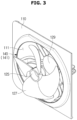
FIG. 3 is a perspective view of a blower in accordance with one embodiment of the present disclosure; -
FIG. 4 is a front view of the blower in accordance with one embodiment of the present disclosure; -
FIG. 5 is a side sectional view of the blower in accordance with one embodiment of the present disclosure; -
FIG. 6 is a view illustrating that a water repellent portion is provided to be divided into a plurality of water repellent members in accordance with one embodiment of the present disclosure; -
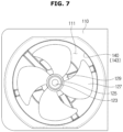
FIG. 7 is a view illustrating that the water repellent portion in accordance with one embodiment of the present disclosure is provided to be coated with a water repellent material; -
FIG. 8 is an exploded perspective view of a blower in accordance with another embodiment of the present disclosure; -
FIG. 9 is a cross-sectional view of the blower in accordance with another embodiment of the present disclosure; -
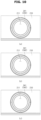
FIG. 10 is a view illustrating that a first water repellent portion is provided to be divided into a plurality of water repellent members in accordance with another embodiment of the present disclosure; -
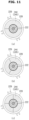
FIG. 11 is a view illustrating that a second water repellent portion is provided to be divided into a plurality of water repellent members in accordance with another embodiment of the present disclosure; -
FIG. 12 is a view illustrating that the first water repellent portion and the second water repellent portion in accordance with another embodiment of the present disclosure are provided to be coated with water repellent materials; -
FIG. 13 is an exploded perspective view of a blower in accordance with still another embodiment of the present disclosure; -
FIG. 14 is a cross-sectional view of the blower in accordance with still another embodiment of the present disclosure; -
FIG. 15 is a view illustrating that a first water repellent portion is provided to be divided into a plurality of water repellent members in an axial direction of a rotary shaft in accordance with still another embodiment of the present disclosure; -
FIG. 16 is a view illustrating that the first water repellent portion in accordance with still another embodiment of the present disclosure is provided to be divided into a plurality of water repellent members in a radial direction of the rotary shaft; and -
FIG. 17 a view illustrating that the first water repellent portion and a second water repellent portion in accordance with still another embodiment of the present disclosure are provided to be coated with water repellent materials. - Hereinafter, embodiments according to the present disclosure will be described in detail with reference to the accompanying drawings.
-
FIG. 1 is a perspective view of a refrigerator in accordance with one embodiment of the present disclosure, andFIG. 2 is a side sectional view of the refrigerator in accordance with one embodiment of the present disclosure. - As shown in
FIGS. 1 to 2 , the refrigerator includes abody 10 forming an exterior thereof, astorage compartment 20 provided in thebody 10 and having an open front surface, adoor 30 pivotally coupled to thebody 10 so that the open front surface of thestorage compartment 20 is opened or closed, and ahinge module 40 including anupper hinge 41 and alower hinge 43 so that thedoor 30 is rotatably coupled to thebody 10. - The
body 10 includes aninner case 11 forming thestorage compartment 20 and anouter case 13 forming the exterior, and an insulating material is foamed between theinner case 11 and theouter case 13 to prevent a discharge of cold air in thestorage compartment 20. - Also, the
body 10 includes apartition 17 configured to divide thestorage compartment 20 into arefrigerator compartment 21 and afreezer compartment 23 located on left and right sides, and amachine room 29, in which acompressor 51 configured to compress a refrigerant and a condenser (not shown) configured to condense the compressed refrigerant are mounted, is provided in a lower rear part of thebody 10. - The
storage compartment 20 is laterally divided by thepartition 17, and therefrigerator compartment 21 is provided on the right side of thebody 10 and thefreezer compartment 23 is provided on the left side of thebody 10. - A plurality of
shelves 25 andcontainers 27 may be provided in thestorage compartment 20 to store food and the like. - The
storage compartment 20 is opened and closed by thedoor 30 pivotably coupled to thebody 10, and therefrigerator compartment 21 and thefreezer compartment 23 laterally separated by thepartition 17 are opened and closed by arefrigerator compartment door 31 and afreezer compartment door 33, respectively. - The
refrigerator compartment door 31 and thefreezer compartment door 33 may be pivotably coupled to thebody 10 by thehinge module 40 including theupper hinge 41 provided on an upper portion of thebody 10 and thelower hinge 43 provided on a lower portion of thebody 10. - A plurality of
door guards 35 are provided on rear surfaces of therefrigerator compartment door 31 and thefreezer compartment door 33 to store food and the like. - A cold air supply device may include the
compressor 51 and the condenser mounted in themachine room 29, anevaporator 53 mounted on a rear surface of thestorage compartment 20 and configured to generate cold air, ablower 100 configured to supply the cold air generated by theevaporator 53 into thestorage compartment 20, acold air duct 55 having a plurality of coldair discharge holes 57 through which the cold air induced by theblower 100 is discharged into thestorage compartment 20, etc. -
FIG. 3 is a perspective view of a blower in accordance with one embodiment of the present disclosure,FIG. 4 is a front view of the blower in accordance with one embodiment of the present disclosure, andFIG. 5 is a side sectional view of the blower in accordance with one embodiment of the present disclosure. - As shown in
FIGS. 3 to 5 , theblower 100 may be provided as an axial flow fan including asuction member 110 into which cold air is introduced and a fan unit 120 configured to supply the cold air introduced through thesuction member 110 to the storage compartment 20 (seeFIG. 2 ). - A cold
air suction hole 111 in a ring shape, through which cold air is introduced, is provided in thesuction member 110, and the fan unit 120 is provided to be separated from the coldair suction hole 111 by a distance greater than or equal to a predetermined distance so that interference between the fan unit 120 and the coldair suction hole 111 is prevented. - Although a ring shape opening provided in the
suction member 110 through which cold air is introduced into thesuction member 110 is referred to as the coldair suction hole 111 when theblower 100 is used in the refrigerator, the ring shape opening provided in thesuction member 110 may be referred to as an air suction hole when theblower 100 is used in a product in which air is introduced into thesuction member 110 other than the refrigerator. - The fan unit 120 includes a
motor 121, ahub 125 connected to themotor 121 by arotary shaft 123, and a plurality ofblades 127 provided to extend in a circumferential direction of thehub 125 from thehub 125. - The
hub 125 located at the center of the plurality ofblades 127 is connected to themotor 121 by therotary shaft 123, and rotary power of themotor 121 is transmitted to thehub 125 through therotary shaft 123 such that thehub 125 and theblades 127 rotate around therotary shaft 123. - Cold air is introduced into the cold
air suction hole 111 of thesuction member 110 due to rotation of theblades 127, and the introduced cold air is discharged through the cold air discharge holes 57 provided in thecold air duct 55 and is supplied to the storage compartment 20 (seeFIG. 2 ). -
Interference prevention portions 130 provided to be separated from the coldair suction hole 111 by a distance greater than or equal to the predetermined distance are provided on end portions of theblades 127 rotated by the motor so that interference between theblades 127 and the coldair suction hole 111 is prevented. - When cold air below zero temperatures, which is generated by the
evaporator 53, is circulated, dew may be frozen and ice may be generated on theinterference prevention portions 130 of theblades 127 and an edge of the coldair suction hole 111. - Particularly, since a temperature of cold air generated by the
evaporator 53 is lower when the cold air is supplied to thefreezer compartment 23 among the storage compartments 20 by theblower 100 than when the cold air is supplied to therefrigerator compartment 21, when the cold air supplied to thefreezer compartment 23 is circulated, dew may be easily frozen and ice may be generated on theinterference prevention portions 130 of theblades 127 and the edge of the cold air suction hole 111 (seeFIG. 2 ). - When ice is generated on the
interference prevention portions 130 of theblades 127 and the edge of the coldair suction hole 111, the coldair suction hole 111 interferes with the rotation of theblades 127 due to the ice and efficiency of theblower 100 is reduced. - Accordingly, the
interference prevention portion 130 and the edge of the coldair suction hole 111 have to be provided to be separated by a sufficient distance so that the coldair suction hole 111 does not interfere with the rotation of theblades 127 due to the ice generated on theinterference prevention portions 130 of theblades 127 and the edge of the coldair suction hole 111. - Since a size of the
blade 127 has to be reduced when a separation distance between theinterference prevention portion 130 and the edge of the coldair suction hole 111 is increased so that the coldair suction hole 111 does not interfere with the rotation of theblades 127, the efficiency of theblower 100 is reduced. - A
water repellent portion 140 treated with a water repellent is provided on the edge of the coldair suction hole 111 adjacent to theinterference prevention portion 130 so that the distance between theinterference prevention portion 130 of theblade 127 and the edge of the coldair suction hole 111 is minimized and the coldair suction hole 111 does not interfere with the rotation of theblades 127 due to the ice generated on theinterference prevention portions 130 and the edge of the coldair suction hole 111. - When the
water repellent portion 140 treated with the water repellent is provided on the edge of the coldair suction hole 111, since dew formed on thewater repellent portion 140 flows more easily down than dew formed on a surface not treated with the water repellent, little dew is formed on thewater repellent portion 140 and an amount of ice is small even when the dew is frozen and the ice is generated. - Since the amount of ice generated between the
interference prevention portion 130 of theblade 127 and the edge of the coldair suction hole 111 is small, a distance H1 between theinterference prevention portion 130 of theblade 127 and the edge of the coldair suction hole 111 may be minimized. - Since the distance H1 between the
interference prevention portion 130 of theblade 127 and the edge of the coldair suction hole 111 can be minimized, the size of theblade 127 can be increased and the efficiency of theblower 100 can be improved. - The
water repellent portion 140 provided on the edge of the coldair suction hole 111 is provided with awater repellent member 141 which is treated with a water repellent material and attached to thewater repellent portion 140. -
FIG. 6 is a view illustrating that a water repellent portion is provided to be divided into a plurality of water repellent members in accordance with one embodiment of the present disclosure. - As shown in
FIG. 6 , when thewater repellent portion 140 is provided with thewater repellent member 141 which is treated with a water repellent material and attached to thewater repellent portion 140, since thewater repellent member 141 may be provided on and attached to only necessary portions to be divided into a plurality ofwater repellent members 141 and each of the plurality of dividedwater repellent members 141 is attached to the edge of the coldair suction hole 111, thewater repellent member 141 may be easily attached to thewater repellent portion 140. - Although the
water repellent member 141 is shown to be divided into two, three, or fourwater repellent members 141 inFIG. 6A to 6C , the embodiments are not limited thereto. -
FIG. 7 is a view illustrating that the water repellent portion in accordance with one embodiment of the present disclosure is provided to be coated with a water repellent material. - As shown in
FIG. 7 , thewater repellent portion 140 coated with awater repellent material 143 may be provided on the edge of the coldair suction hole 111. - Next, a blower according to another embodiment will be described with reference to
FIGS. 8 to 12 . -
FIG. 8 is an exploded perspective view of a blower in accordance with another embodiment of the present disclosure, andFIG. 9 is a cross-sectional view of the blower in accordance with another embodiment of the present disclosure. - As shown in
FIGS. 8 and9 , ablower 200 may be provided as a centrifugal fan including asuction member 210 into which cold air is introduced and afan unit 220 configured to supply the cold air introduced through thesuction member 210 to the storage compartment 20 (seeFIG. 2 ). - A cold
air suction hole 211 in a ring shape, through which the cold air is introduced, is provided in thesuction member 210. - Although a ring shape opening provided in the
suction member 210 through which cold air is introduced into thesuction member 210 is referred to as the coldair suction hole 211 when theblower 200 is used in a refrigerator, the ring shape opening provided in thesuction member 210 may be referred to as an air suction hole when theblower 200 is used in a product in which air is introduced into thesuction member 210 other than the refrigerator. - The
fan unit 220 includes amotor 221, abase 223 having ahub 224 connected to themotor 221 by arotary shaft 222, aring member 225 in a ring shape, which is provided to be separated from the base 223 in an axial direction of therotary shaft 222 and has an opening in a center portion thereof, a plurality ofblades 227 provided between the base 223 and thering member 225, and abase plate 228 on which themotor 221 is mounted. - A plurality of
couplers 229 may be provided on thebase plate 228 so that thebase plate 228 may be coupled to other devices. - The
hub 224 of the base 223 located at the center of the plurality ofblades 227 is connected to themotor 221 by therotary shaft 222, and rotary power of themotor 221 is transmitted tohub 224 through therotary shaft 222 so that thebase 223,ring member 225 and theblades 227 rotate around therotary shaft 222. - Cold air is introduced into the cold
air suction hole 211 of thesuction member 210 due to rotation of theblades 227, and the introduced cold air is discharged through the cold air discharge holes 57 provided in thecold air duct 55 and may be supplied to thestorage compartment 20. - Among the base 223, the
ring member 225 and theblades 227 rotated by themotor 221, thering member 225 is provided to be adjacent to thesuction member 210, and thebase 223 is provided to be adjacent to thebase plate 228. - In the
ring member 225 and the base 223 disposed adjacent to thesuction member 210 and thebase plate 228, respectively,interference prevention portions ring member 225 opposite thesuction member 210 and one surface of the base 223 opposite thebase plate 228, respectively, to prevent interference between thesuction member 210 and thebase plate 228. - The
interference prevention portions interference prevention portion 231 provided on the one surface of thering member 225 and the secondinterference prevention portion 233 provided on the one surface of thebase 223. - When cold air below zero temperatures, which is generated by the
evaporator 53, is circulated, dew may be frozen and ice may be generated on the firstinterference prevention portion 231, one surface of thesuction member 210 opposite the firstinterference prevention portion 231, the secondinterference prevention portion 233, and one surface of thebase plate 228 opposite the secondinterference prevention portion 233. - Particularly, since a temperature of cold air generated by the
evaporator 53 is lower when the cold air is supplied to thefreezer compartment 23 among the storage compartments 20 by theblower 200 than when the cold air is supplied to therefrigerator compartment 21, when the cold air supplied to thefreezer compartment 23 is circulated, dew may be easily frozen and ice may be generated on the firstinterference prevention portion 231, the one surface of thesuction member 210 opposite the firstinterference prevention portion 231, the secondinterference prevention portion 233, and the one surface of thebase plate 228 opposite the second interference prevention portion 233 (seeFIG. 2 ). - When ice is generated between the first
interference prevention portion 231 and thesuction member 210 and generated between the secondinterference prevention portion 233 and thebase plate 228, thesuction member 210 and thebase plate 228 interfere with rotation of thefan unit 220 due to the ice, and efficiency of theblower 200 is reduced. - Accordingly, distances between the first
interference prevention portion 231 and thesuction member 210 and between the secondinterference prevention portion 233 and thebase plate 228 have to be adequately provided so that the ice generated between the firstinterference prevention portion 231 and thesuction member 210 and between the secondinterference prevention portion 233 and thebase plate 228 does not interfere with the rotation of thefan unit 220. - Since a size of the
blade 227 has to be reduced when the separation distances between the firstinterference prevention portion 231 andsuction member 210 and between the secondinterference prevention portion 233 and thebase plate 228 are increased so that thesuction member 210 and thebase plate 228 do not interfere with the rotation of thefan unit 220, the efficiency of theblower 200 is reduced. - Also, cold air introduced in the axial direction of the
rotary shaft 222 is discharged in a circumferential direction of therotary shaft 222, and some of the discharged cold air is reintroduced through separation gaps between the firstinterference prevention portion 231 and thesuction member 210 and between the secondinterference prevention portion 233 and thebase plate 228 such that the efficiency of theblower 200 is reduced. - Since the amount of reintroduced cold air is increased when the separation gaps between the first
interference prevention portion 231 and thesuction member 210 and between the secondinterference prevention portion 233 and thebase plate 228 are widened, the efficiency of theblower 200 is further reduced. -
Water repellent portions suction member 210 opposite the firstinterference prevention portion 231 and the one surface of thebase plate 228 opposite the secondinterference prevention portion 233 so that the distances between the firstinterference prevention portion 231 andsuction member 210 and between the secondinterference prevention portion 233 and thebase plate 228 are minimized and ice generated on the firstinterference prevention portion 231, thesuction member 210, the secondinterference prevention portion 233, and thebase plate 228 does not interfere with the rotation of thefan unit 220. - The
water repellent portions water repellent portion 241 provided on the one surface of thesuction member 210 opposite the firstinterference prevention portion 231 and the secondwater repellent portion 244 provided on the one surface of thebase plate 228 opposite the secondinterference prevention portion 233. - When the
water repellent portions suction member 210 opposite the firstinterference prevention portion 231 and the one surface of thebase plate 228 opposite the secondinterference prevention portion 233, since dew formed on thewater repellent portions water repellent portions - Since the amount of ice generated on the
water repellent portions water repellent portion 241 and the firstinterference prevention portion 231 and a distance H3 between secondwater repellent portion 244 and the secondinterference prevention portion 233 may be minimized. - Since the distance H2 between the first
water repellent portion 241 and the firstinterference prevention portion 231 and the distance H3 between secondwater repellent portion 244 and the secondinterference prevention portion 233 may be minimized, the size of theblade 227 may be increased and the efficiency of theblower 200 can be improved. - The first
water repellent portion 241 and the secondwater repellent portion 244 are respectively provided withwater repellent members water repellent portion 241 and the secondwater repellent portion 244. -
FIG. 10 is a view illustrating that a first water repellent portion is provided to be divided into a plurality of water repellent members in accordance with another embodiment of the present disclosure, andFIG. 11 is a view illustrating that a second water repellent portion is provided to be divided into a plurality of water repellent members in accordance with another embodiment of the present disclosure. - As shown in
FIGS. 10 and11 , when a firstwater repellent portion 241 and a secondwater repellent portion 244 are respectively provided withwater repellent members water repellent portion 241 and the secondwater repellent portion 244, since thewater repellent members water repellent members 242 and 252 and the plurality of dividedwater repellent members suction member 210 or abase plate 228, thewater repellent members suction member 210 or thebase plate 228. - Although the
water repellent member 242 is shown to be divided into two, three, and fourwater repellent members 242 inFIG. 10A to 10C and thewater repellent member 245 is shown to be divided into two, three, and fourwater repellent members 245 inFIG. 11A to 11C , the embodiments are not limited thereto. -
FIG. 12 is a view illustrating that the first water repellent portion and the second water repellent portion in accordance with another embodiment of the present disclosure are provided to be coated with water repellent materials. - As shown in
FIG. 12 , a firstwater repellent portion 241 and a secondwater repellent portion 244 which are coated withwater repellent materials - Although both the first
water repellent portion 241 and the secondwater repellent portion 244 are shown to be coated with thewater repellent materials water repellent portion 241 and the secondwater repellent portion 244 may be coated with the water repellent material and provided and the other water repellent portion may be provided with a water repellent member treated with a water repellent. - Next, a blower according to still another embodiment will be described with reference to
FIGS. 13 to 17 . -
FIG. 13 is an exploded perspective view of a blower in accordance with still another embodiment of the present disclosure, andFIG. 14 is a cross-sectional view of the blower in accordance with still another embodiment of the present disclosure. - As shown in
FIGS. 13 and14 , ablower 300 may be provided as a mixed flow fan including asuction member 310 into which cold air is introduced and a fan unit 320 configured to supply the cold air introduced through thesuction member 310 to a storage compartment 20 (seeFIG. 2 ). - A ring shape cold
air suction hole 311 through which cold air is introduced is provided in thesuction member 310. - Although a ring shape opening provided in the
suction member 310 through which cold air is introduced into thesuction member 310 is referred to as the coldair suction hole 311 when theblower 300 is used in a refrigerator, the ring shape opening provided in thesuction member 310 may be referred to as an air suction hole when theblower 300 is used in a product in which air is introduced into thesuction member 310 other than the refrigerator. - The fan unit 320 includes a
motor 321, ahub 325 connected to themotor 321 by arotary shaft 323, a plurality ofblades 327 provided on an outer circumferential surface of thehub 325, and abase plate 329 on which themotor 321 is mounted. - When rotary power of the
motor 321 is transmitted to thehub 325 and thehub 325 rotates around therotary shaft 323, theblades 327 formed on the outer circumferential surface of thehub 325 are also rotated together with thehub 325. - Cold air is introduced into the cold
air suction hole 311 of thesuction member 310 due to rotation of theblades 327, and the introduced cold air is discharged through the cold air discharge holes 57 provided in thecold air duct 55 and may be supplied to thestorage compartment 20. - An end portion of the
blade 327 rotated by themotor 221 is provided to be adjacent to thesuction member 310, and a surface opposite a surface of thehub 325 on which theblades 327 are provided is provided to be adjacent to thebase plate 329. -
Interference prevention portions blade 327, which is disposed adjacent to thesuction member 310 and thebase plate 329, and the surface opposite the surface of thehub 325 on which theblades 327 are provided so that the end portion of theblade 327, which is disposed adjacent to thesuction member 310 and thebase plate 329, and the surface opposite the surface of thehub 325 on which theblades 327 are provided are provided to prevent interference between thesuction member 310 and thebase plate 329. - The
interference prevention portions interference prevention portion 331 provided on the end portion of theblade 327 and the secondinterference prevention portion 333 provided on one surface of thehub 325. - When cold air below zero temperatures, which is generated by the
evaporator 53, is circulated, dew may be frozen and ice may be generated on the firstinterference prevention portion 331, one surface of thesuction member 310 opposite the firstinterference prevention portion 331, the secondinterference prevention portion 333, and one surface of thebase plate 329 opposite the secondinterference prevention portion 333. - Particularly, as a temperature of cold air generated by the
evaporator 53 is lower when the cold air is supplied to afreezer compartment 23 among the storage compartments 20 by theblower 300 than when the cold air is supplied to arefrigerator compartment 21, when the cold air supplied to thefreezer compartment 23 is circulated, dew may be easily frozen and ice may be generated on the firstinterference prevention portion 331, the one surface of thesuction member 310 opposite the firstinterference prevention portion 331, the secondinterference prevention portion 333, and the one surface of thebase plate 329 opposite the second interference prevention portion 333 (seeFIG. 2 ). - Distances between the first
interference prevention portion 331 and thesuction member 310 and between the secondinterference prevention portion 333 and thebase plate 329 have to be adequately provided so that the ice generated between the firstinterference prevention portion 331 andsuction member 310 and between the secondinterference prevention portion 333 and thebase plate 329 does not interfere with rotation of the fan unit 320. - Since a size of the
blade 327 has to be reduced when the separation distances between the firstinterference prevention portion 331 andsuction member 310 and between the secondinterference prevention portion 333 and thebase plate 329 are increased so that thesuction member 310 and thebase plate 329 do not interfere with the rotation of the fan unit 320, the efficiency of theblower 300 is reduced. -
Water repellent portions suction member 310 opposite the firstinterference prevention portion 331 and the one surface of thebase plate 329 opposite the secondinterference prevention portion 333 so that the distances between the firstinterference prevention portion 331 andsuction member 310 and between the secondinterference prevention portion 333 and thebase plate 329 are minimized and ice generated on the firstinterference prevention portion 331,suction member 310, the secondinterference prevention portion 333, and thebase plate 329 does not interfere with the rotation of the fan unit 320. - The
water repellent portions water repellent portion 341 provided on the one surface of thesuction member 310 opposite the firstinterference prevention portion 331 and the secondwater repellent portion 344 provided on the one surface of thebase plate 329 opposite the secondinterference prevention portion 333. - When the
water repellent portions suction member 310 opposite the firstinterference prevention portion 331 and the one surface of thebase plate 329 opposite the secondinterference prevention portion 333, as dew formed on thewater repellent portions water repellent portions - Since the amount of ice generated on the
water repellent portions water repellent portion 341 and the firstinterference prevention portion 331 and a distance H5 between secondwater repellent portion 344 and the secondinterference prevention portion 333 may be minimized. - Since the distance H4 between the first
water repellent portion 341 and the firstinterference prevention portion 331 and the distance H5 between secondwater repellent portion 344 and the secondinterference prevention portion 333 may be minimized, the size of theblade 327 can be increased and the efficiency of theblower 300 can be improved. - The first
water repellent portion 341 and the secondwater repellent portion 344 are respectively provided withwater repellent members water repellent portion 341 and the secondwater repellent portion 344. -
FIG. 15 is a view illustrating that a first water repellent portion is provided to be divided into a plurality of water repellent members in an axial direction of a rotary shaft in accordance with still another embodiment of the present disclosure, andFIG. 16 is a view illustrating that the first water repellent portion in accordance with still another embodiment of the present disclosure is provided to be divided into a plurality of water repellent members in a radial direction of the rotary shaft. - When a first
water repellent portion 341 is provided with awater repellent member 342 treated with a water repellent, thewater repellent member 342 is provided to be divided into a plurality ofwater repellent members 342 in a shaft direction of therotary shaft 323, as shown inFIG. 15 , or thewater repellent member 342 is provided to be divided into a plurality ofwater repellent members 342 in a radial direction of therotary shaft 323, as shown inFIG. 16 . - Since the first
water repellent portion 341 may be provided on and attached to only necessary portions to be divided into a plurality ofwater repellent portions 341 and each of the plurality of dividedwater repellent members 342 is attached to thesuction member 310 and thebase plate 329, the firstwater repellent portion 341 may be easily attached to thesuction member 310 and thebase plate 329. - Although the
water repellent member 342 is shown to be divided into two and threewater repellent members 342 inFIG. 15A and 15B and thewater repellent member 342 is shown to be divided into two, three, and fourwater repellent members 342 inFIG. 16A to 16C , the embodiments are not limited thereto. -
FIG. 17 a view illustrating that the first water repellent portion and a second water repellent portion are provided to be coated with water repellent materials in accordance with still another embodiment of the present disclosure. - As shown in
FIG. 17 , a firstwater repellent portion 341 and a secondwater repellent portion 344 coated withwater repellent materials - Although both the first
water repellent portion 341 and the secondwater repellent portion 344 are shown as being coated with thewater repellent materials water repellent portion 341 and the secondwater repellent portion 344 may be coated with the water repellent material and provided and the other one of the water repellent portions may be provided with a water repellent member treated with a water repellent. - As is apparent from the above description, efficiency of a blower can be improved so that a separation distance between an end of the blade and a suction member can be minimized.
- Although particular shapes and directions of a blower and a refrigerator having the same have been mainly described while describing the blower and the refrigerator having the same with reference to the accompanying drawings, those skilled in the art should understand that the present disclosure may be modified and changed as long as such modifications and changes are included in the scope of the present invention as defined by the appended claims.
Claims (13)
- A refrigerator comprising:a body (10) including a freezer compartment (23);an evaporator (53) provided outside the freezer compartment (23) and configured to generate cold air; anda blower (100) configured to supply the cold air generated by the evaporator (53) into the freezer compartment (23),wherein the blower (100, 200, 300) includes:a suction member (110, 210, 310) having a body and a cold air suction hole (111, 211, 311) formed in the body, wherein the body is configured to guide air to the cold air suction hole (111, 211, 311); anda fan (120, 220, 320) configured to supply the cold air, generated by the evaporator (53) and introduced through the cold air suction hole (111, 211, 311), into the freezer compartment (23), and the fan (120, 220, 320) having a first interference prevention portion located at a portion of the fan (120, 220, 320) closest to the suction member and provided to be separated from the suction member (110, 210, 310) by a distance greater than or equal to a predetermined distance to prevent interference between the fan (120, 220, 320) and the suction member (110, 210, 310),characterized in thatthe suction member (110, 210, 310) further includes a first water repellent portion (140, 241, 341) provided with a water repellent member (141, 242, 342) which is treated with a water repellent material and attached to one surface of the suction member (110, 210, 310) opposite the fan (120, 220, 320) and adjacent to the first interference prevention portion of the fan to reduce an amount of ice formed on the water repellent member (141, 242, 342).
- The refrigerator according to claim 1, wherein:the fan includes a motor (121, 221, 321), a hub (125, 224, 325) connected to the motor by a rotary shaft (123, 222, 323), and a plurality of blades (127, 227, 327) provided to extend in a radial direction from the hub; andthe first interference prevention portion is provided on an end portion furthest from the hub of each of the plurality of blades.
- The refrigerator according to claim 1, wherein the water repellent member is provided to be divided into a plurality of water repellent members, and each of plurality of the water repellent members is attached to the edge of the cold air suction hole.
- The refrigerator according to any one of the preceding claims, wherein the fan further includes a motor (121, 221, 321), a base (223) having a hub (125, 224, 325) connected to the motor by a rotary shaft (123, 222, 323), a ring member (225) in a ring shape, which is provided to be separated from the base in an axial direction of the rotary shaft and has an opening in a center portion of the ring member, a plurality of blades (127, 227, 327) provided between the base and the ring member, and a base plate (228, 329) on which the motor is mounted.
- The refrigerator according to claim 4, wherein the first interference prevention portion is provided on the ring member and spaced apart from the suction member and the fan also includes a second interference prevention portion which is a portion of the fan closest to the base plate and is provided on the base of the fan and spaced apart from the base plate.
- The refrigerator according to claim 5, wherein the water repellent portion includes:
a second water repellent portion (244, 344) provided with the water repellent member which is coated with the water repellent and attached to a surface of the base plate adjacent to the second interference prevention portion. - The refrigerator according to claim 6, wherein the first water repellent portion and the second water repellent portion are provided so that the water repellent member is divided into a plurality of water repellent members and attached to the first water repellent portion and the second water repellent portion.
- The refrigerator according to any one of claims 5 to 7, wherein the water repellent portion further includes:a second water repellent portion (241, 341) provided such that a water repellent material is coated on a surface of the suction member adjacent to the first interference prevention portion; andthe suction member further includes a third water repellent portion (244, 344) provided such that the water repellent material is coated on a surface of the base plate adjacent to the second interference prevention portion.
- The refrigerator according to any one of the preceding claims, wherein the fan further includes:a motor (121, 221, 321);a hub (125, 224, 325) connected to the motor by a rotary shaft (123, 222, 323);a plurality of blades (127, 227, 327) provided on an outer circumferential surface of the hub; anda base plate (228, 329) on which the motor is mounted.
- The refrigerator according to claim 9, wherein the first interference prevention portion is an end portion (231, 331) furthest from the hub of each of the plurality of blades; and
the fan includes a second interference prevention portion which is a portion of the fan closest to the base plate and is spaced apart from the base plate. - The refrigerator according to claim 10, wherein the water repellent portion includes:
a second water repellent portion (244, 344) provided with the water repellent member which is treated with the water repellent and attached to a surface of the base plate adjacent to the second interference prevention portion. - The refrigerator according to claim 11, wherein the first water repellent portion is provided so that the water repellent member is divided into a plurality of water repellent members and attached to the first water repellent portion.
- The refrigerator according to any one of claims 10 to 12, wherein the water repellent portion further includes:a second water repellent portion (241, 341) provided such that a water repellent material is coated on a surface of the suction member adjacent to the first interference prevention portion; andthe suction member further includes a third water repellent portion (244, 344) provided such that the water repellent material is coated on a surface of the base plate adjacent to the second interference prevention portion.
Applications Claiming Priority (1)
| Application Number | Priority Date | Filing Date | Title |
|---|---|---|---|
| KR1020160121968A KR102559749B1 (en) | 2016-09-23 | 2016-09-23 | Blower and refrigerator having the same |
Publications (2)
| Publication Number | Publication Date |
|---|---|
| EP3299751A1 EP3299751A1 (en) | 2018-03-28 |
| EP3299751B1 true EP3299751B1 (en) | 2025-06-25 |
Family
ID=59955495
Family Applications (1)
| Application Number | Title | Priority Date | Filing Date |
|---|---|---|---|
| EP17192759.3A Active EP3299751B1 (en) | 2016-09-23 | 2017-09-22 | Blower and refrigerator having the same |
Country Status (4)
| Country | Link |
|---|---|
| US (1) | US10684057B2 (en) |
| EP (1) | EP3299751B1 (en) |
| KR (1) | KR102559749B1 (en) |
| CN (1) | CN107869876B (en) |
Families Citing this family (1)
| Publication number | Priority date | Publication date | Assignee | Title |
|---|---|---|---|---|
| CN110966818B (en) * | 2018-09-29 | 2022-10-28 | 青岛海尔特种电冰柜有限公司 | Air-cooled refrigerating device |
Family Cites Families (19)
| Publication number | Priority date | Publication date | Assignee | Title |
|---|---|---|---|---|
| JPS567967A (en) | 1979-06-27 | 1981-01-27 | Fuji Electric Co Ltd | Blower for appliance for refrigeration or cold storage |
| JPH0727468A (en) * | 1993-07-09 | 1995-01-27 | Fuji Electric Co Ltd | Showcase |
| JPH10103846A (en) | 1996-09-26 | 1998-04-24 | Sanyo Electric Co Ltd | Honeycomb for cold air discharging port and cooled open showcase |
| JP2000199498A (en) * | 1998-12-28 | 2000-07-18 | Kurita Denki Seisakusho:Kk | Blower |
| CA2476592A1 (en) | 2002-02-28 | 2003-09-04 | Marc A. Paradis | Method and apparatus for cooling and dehumidifying air |
| JP3793173B2 (en) * | 2002-11-25 | 2006-07-05 | エルジー電子株式会社 | Blower for cold air circulation in refrigerator |
| JP2005120991A (en) * | 2003-10-20 | 2005-05-12 | Fukushima Industries Corp | Refrigerated showcase box type fan |
| CN101004181A (en) * | 2006-01-17 | 2007-07-25 | 台达电子工业股份有限公司 | Fan and its motor |
| KR100850959B1 (en) | 2007-04-04 | 2008-08-12 | 엘지전자 주식회사 | Refrigerator with blower and blower |
| JP2009257603A (en) | 2008-04-11 | 2009-11-05 | Mitsubishi Heavy Ind Ltd | Outdoor unit of air conditioner |
| CN201335029Y (en) * | 2009-01-13 | 2009-10-28 | 邢一强 | Fan with waterproof structure |
| JP5456021B2 (en) * | 2009-03-19 | 2014-03-26 | 三菱電機株式会社 | Coating composition, coating method, air conditioner, exhaust fan, and electrical equipment |
| JP2010242597A (en) | 2009-04-03 | 2010-10-28 | Daikin Ind Ltd | Axial flow fan and air conditioner |
| KR20110041659A (en) * | 2009-10-16 | 2011-04-22 | 주식회사 대우일렉트로닉스 | Double door refrigerator |
| CN102102928B (en) * | 2009-12-22 | 2014-08-27 | 博西华家用电器有限公司 | Refrigerator and fan component for refrigerator |
| DE102010032619A1 (en) | 2010-07-29 | 2012-02-02 | Wilo Se | Coating composition with titanium dioxide-generating agent, nanoscale coating based on titanium dioxide, its production, further processing and use |
| JP6048422B2 (en) | 2014-02-04 | 2016-12-21 | 三菱電機株式会社 | Air conditioner outdoor unit |
| JP6213320B2 (en) * | 2014-03-17 | 2017-10-18 | 三菱電機株式会社 | Outdoor blower |
| CN204718247U (en) * | 2015-04-30 | 2015-10-21 | 合肥华凌股份有限公司 | Refrigerator |
-
2016
- 2016-09-23 KR KR1020160121968A patent/KR102559749B1/en active Active
-
2017
- 2017-09-22 US US15/712,623 patent/US10684057B2/en active Active
- 2017-09-22 EP EP17192759.3A patent/EP3299751B1/en active Active
- 2017-09-22 CN CN201710866259.8A patent/CN107869876B/en active Active
Also Published As
| Publication number | Publication date |
|---|---|
| KR102559749B1 (en) | 2023-07-27 |
| KR20180032835A (en) | 2018-04-02 |
| US20180087820A1 (en) | 2018-03-29 |
| CN107869876B (en) | 2021-06-08 |
| CN107869876A (en) | 2018-04-03 |
| EP3299751A1 (en) | 2018-03-28 |
| US10684057B2 (en) | 2020-06-16 |
Similar Documents
| Publication | Publication Date | Title |
|---|---|---|
| CN109716046B (en) | Refrigerator with a door | |
| EP2975341B1 (en) | Refrigerator | |
| KR100918445B1 (en) | Fan unit of refrigerator | |
| CN207471891U (en) | Blower device and the refrigerator for having the blower device | |
| KR20220016929A (en) | Refrigerator | |
| KR200143520Y1 (en) | A refrigerator | |
| US10684057B2 (en) | Blower and refrigerator having the same | |
| CN110392812A (en) | Freezer | |
| US11428454B2 (en) | Refrigerator | |
| KR200463568Y1 (en) | Refrigerator | |
| KR20160005987A (en) | Refrigerator | |
| KR100504048B1 (en) | Refrigerator | |
| KR200217540Y1 (en) | Refrigerator | |
| KR20170093581A (en) | Refrigerator | |
| KR20210156162A (en) | Refrigerator | |
| KR20000005840U (en) | Refrigerator | |
| KR20000051163A (en) | Cooling air circulation apparatus for refrigerator | |
| JP2020098045A (en) | Shielding device and refrigerator equipped with the same | |
| KR100217799B1 (en) | Cold Distributor of Refrigerator | |
| KR200180230Y1 (en) | Refrigerator | |
| KR100234067B1 (en) | Refrigerator having air distribution apparatus | |
| KR100238977B1 (en) | Cold Distributor for Refrigerator | |
| KR100923260B1 (en) | Cold return duct blocking device of the refrigerator | |
| KR20040105033A (en) | Refrigerator | |
| KR100238978B1 (en) | Refrigerator with cold air distributor |
Legal Events
| Date | Code | Title | Description |
|---|---|---|---|
| PUAI | Public reference made under article 153(3) epc to a published international application that has entered the european phase |
Free format text: ORIGINAL CODE: 0009012 |
|
| STAA | Information on the status of an ep patent application or granted ep patent |
Free format text: STATUS: THE APPLICATION HAS BEEN PUBLISHED |
|
| AK | Designated contracting states |
Kind code of ref document: A1 Designated state(s): AL AT BE BG CH CY CZ DE DK EE ES FI FR GB GR HR HU IE IS IT LI LT LU LV MC MK MT NL NO PL PT RO RS SE SI SK SM TR |
|
| AX | Request for extension of the european patent |
Extension state: BA ME |
|
| STAA | Information on the status of an ep patent application or granted ep patent |
Free format text: STATUS: REQUEST FOR EXAMINATION WAS MADE |
|
| 17P | Request for examination filed |
Effective date: 20180626 |
|
| RBV | Designated contracting states (corrected) |
Designated state(s): AL AT BE BG CH CY CZ DE DK EE ES FI FR GB GR HR HU IE IS IT LI LT LU LV MC MK MT NL NO PL PT RO RS SE SI SK SM TR |
|
| STAA | Information on the status of an ep patent application or granted ep patent |
Free format text: STATUS: EXAMINATION IS IN PROGRESS |
|
| 17Q | First examination report despatched |
Effective date: 20200217 |
|
| RIC1 | Information provided on ipc code assigned before grant |
Ipc: F04D 29/60 20060101ALI20241213BHEP Ipc: F04D 29/16 20060101ALI20241213BHEP Ipc: F04D 19/00 20060101ALI20241213BHEP Ipc: F25D 21/04 20060101ALI20241213BHEP Ipc: F25D 17/06 20060101AFI20241213BHEP |
|
| GRAP | Despatch of communication of intention to grant a patent |
Free format text: ORIGINAL CODE: EPIDOSNIGR1 |
|
| STAA | Information on the status of an ep patent application or granted ep patent |
Free format text: STATUS: GRANT OF PATENT IS INTENDED |
|
| INTG | Intention to grant announced |
Effective date: 20250205 |
|
| GRAS | Grant fee paid |
Free format text: ORIGINAL CODE: EPIDOSNIGR3 |
|
| GRAA | (expected) grant |
Free format text: ORIGINAL CODE: 0009210 |
|
| STAA | Information on the status of an ep patent application or granted ep patent |
Free format text: STATUS: THE PATENT HAS BEEN GRANTED |
|
| AK | Designated contracting states |
Kind code of ref document: B1 Designated state(s): AL AT BE BG CH CY CZ DE DK EE ES FI FR GB GR HR HU IE IS IT LI LT LU LV MC MK MT NL NO PL PT RO RS SE SI SK SM TR |
|
| REG | Reference to a national code |
Ref country code: GB Ref legal event code: FG4D |
|
| REG | Reference to a national code |
Ref country code: CH Ref legal event code: EP |
|
| REG | Reference to a national code |
Ref country code: DE Ref legal event code: R096 Ref document number: 602017090107 Country of ref document: DE |
|
| REG | Reference to a national code |
Ref country code: CH Ref legal event code: EP |
|
| REG | Reference to a national code |
Ref country code: IE Ref legal event code: FG4D |
|
| PG25 | Lapsed in a contracting state [announced via postgrant information from national office to epo] |
Ref country code: FI Free format text: LAPSE BECAUSE OF FAILURE TO SUBMIT A TRANSLATION OF THE DESCRIPTION OR TO PAY THE FEE WITHIN THE PRESCRIBED TIME-LIMIT Effective date: 20250625 |
|
| PGFP | Annual fee paid to national office [announced via postgrant information from national office to epo] |
Ref country code: DE Payment date: 20250820 Year of fee payment: 9 |
|
| REG | Reference to a national code |
Ref country code: LT Ref legal event code: MG9D |
|
| PG25 | Lapsed in a contracting state [announced via postgrant information from national office to epo] |
Ref country code: GR Free format text: LAPSE BECAUSE OF FAILURE TO SUBMIT A TRANSLATION OF THE DESCRIPTION OR TO PAY THE FEE WITHIN THE PRESCRIBED TIME-LIMIT Effective date: 20250926 Ref country code: NO Free format text: LAPSE BECAUSE OF FAILURE TO SUBMIT A TRANSLATION OF THE DESCRIPTION OR TO PAY THE FEE WITHIN THE PRESCRIBED TIME-LIMIT Effective date: 20250925 |
|
| PG25 | Lapsed in a contracting state [announced via postgrant information from national office to epo] |
Ref country code: BG Free format text: LAPSE BECAUSE OF FAILURE TO SUBMIT A TRANSLATION OF THE DESCRIPTION OR TO PAY THE FEE WITHIN THE PRESCRIBED TIME-LIMIT Effective date: 20250625 |
|
| PG25 | Lapsed in a contracting state [announced via postgrant information from national office to epo] |
Ref country code: HR Free format text: LAPSE BECAUSE OF FAILURE TO SUBMIT A TRANSLATION OF THE DESCRIPTION OR TO PAY THE FEE WITHIN THE PRESCRIBED TIME-LIMIT Effective date: 20250625 |
|
| PG25 | Lapsed in a contracting state [announced via postgrant information from national office to epo] |
Ref country code: RS Free format text: LAPSE BECAUSE OF FAILURE TO SUBMIT A TRANSLATION OF THE DESCRIPTION OR TO PAY THE FEE WITHIN THE PRESCRIBED TIME-LIMIT Effective date: 20250925 |
|
| PG25 | Lapsed in a contracting state [announced via postgrant information from national office to epo] |
Ref country code: LV Free format text: LAPSE BECAUSE OF FAILURE TO SUBMIT A TRANSLATION OF THE DESCRIPTION OR TO PAY THE FEE WITHIN THE PRESCRIBED TIME-LIMIT Effective date: 20250625 |
|
| REG | Reference to a national code |
Ref country code: NL Ref legal event code: MP Effective date: 20250625 |
|
| PG25 | Lapsed in a contracting state [announced via postgrant information from national office to epo] |
Ref country code: NL Free format text: LAPSE BECAUSE OF FAILURE TO SUBMIT A TRANSLATION OF THE DESCRIPTION OR TO PAY THE FEE WITHIN THE PRESCRIBED TIME-LIMIT Effective date: 20250625 |
|
| PG25 | Lapsed in a contracting state [announced via postgrant information from national office to epo] |
Ref country code: PT Free format text: LAPSE BECAUSE OF FAILURE TO SUBMIT A TRANSLATION OF THE DESCRIPTION OR TO PAY THE FEE WITHIN THE PRESCRIBED TIME-LIMIT Effective date: 20251027 |
|
| REG | Reference to a national code |
Ref country code: AT Ref legal event code: MK05 Ref document number: 1806800 Country of ref document: AT Kind code of ref document: T Effective date: 20250625 |
|
| PG25 | Lapsed in a contracting state [announced via postgrant information from national office to epo] |
Ref country code: IS Free format text: LAPSE BECAUSE OF FAILURE TO SUBMIT A TRANSLATION OF THE DESCRIPTION OR TO PAY THE FEE WITHIN THE PRESCRIBED TIME-LIMIT Effective date: 20251025 |
|
| PG25 | Lapsed in a contracting state [announced via postgrant information from national office to epo] |
Ref country code: AT Free format text: LAPSE BECAUSE OF FAILURE TO SUBMIT A TRANSLATION OF THE DESCRIPTION OR TO PAY THE FEE WITHIN THE PRESCRIBED TIME-LIMIT Effective date: 20250625 Ref country code: SM Free format text: LAPSE BECAUSE OF FAILURE TO SUBMIT A TRANSLATION OF THE DESCRIPTION OR TO PAY THE FEE WITHIN THE PRESCRIBED TIME-LIMIT Effective date: 20250625 |
|
| PG25 | Lapsed in a contracting state [announced via postgrant information from national office to epo] |
Ref country code: CZ Free format text: LAPSE BECAUSE OF FAILURE TO SUBMIT A TRANSLATION OF THE DESCRIPTION OR TO PAY THE FEE WITHIN THE PRESCRIBED TIME-LIMIT Effective date: 20250625 |
|
| PG25 | Lapsed in a contracting state [announced via postgrant information from national office to epo] |
Ref country code: PL Free format text: LAPSE BECAUSE OF FAILURE TO SUBMIT A TRANSLATION OF THE DESCRIPTION OR TO PAY THE FEE WITHIN THE PRESCRIBED TIME-LIMIT Effective date: 20250625 |
|
| PG25 | Lapsed in a contracting state [announced via postgrant information from national office to epo] |
Ref country code: EE Free format text: LAPSE BECAUSE OF FAILURE TO SUBMIT A TRANSLATION OF THE DESCRIPTION OR TO PAY THE FEE WITHIN THE PRESCRIBED TIME-LIMIT Effective date: 20250625 |
|
| PG25 | Lapsed in a contracting state [announced via postgrant information from national office to epo] |
Ref country code: SK Free format text: LAPSE BECAUSE OF FAILURE TO SUBMIT A TRANSLATION OF THE DESCRIPTION OR TO PAY THE FEE WITHIN THE PRESCRIBED TIME-LIMIT Effective date: 20250625 Ref country code: RO Free format text: LAPSE BECAUSE OF FAILURE TO SUBMIT A TRANSLATION OF THE DESCRIPTION OR TO PAY THE FEE WITHIN THE PRESCRIBED TIME-LIMIT Effective date: 20250625 |
|
| PG25 | Lapsed in a contracting state [announced via postgrant information from national office to epo] |
Ref country code: ES Free format text: LAPSE BECAUSE OF FAILURE TO SUBMIT A TRANSLATION OF THE DESCRIPTION OR TO PAY THE FEE WITHIN THE PRESCRIBED TIME-LIMIT Effective date: 20250625 |
|
| PG25 | Lapsed in a contracting state [announced via postgrant information from national office to epo] |
Ref country code: DK Free format text: LAPSE BECAUSE OF FAILURE TO SUBMIT A TRANSLATION OF THE DESCRIPTION OR TO PAY THE FEE WITHIN THE PRESCRIBED TIME-LIMIT Effective date: 20250625 |
|
| PG25 | Lapsed in a contracting state [announced via postgrant information from national office to epo] |
Ref country code: IT Free format text: LAPSE BECAUSE OF FAILURE TO SUBMIT A TRANSLATION OF THE DESCRIPTION OR TO PAY THE FEE WITHIN THE PRESCRIBED TIME-LIMIT Effective date: 20250625 |
|
| PLBE | No opposition filed within time limit |
Free format text: ORIGINAL CODE: 0009261 |
|
| STAA | Information on the status of an ep patent application or granted ep patent |
Free format text: STATUS: NO OPPOSITION FILED WITHIN TIME LIMIT |
|
| REG | Reference to a national code |
Ref country code: CH Ref legal event code: H13 Free format text: ST27 STATUS EVENT CODE: U-0-0-H10-H13 (AS PROVIDED BY THE NATIONAL OFFICE) Effective date: 20260504 |
|
| REG | Reference to a national code |
Ref country code: CH Ref legal event code: L10 Free format text: ST27 STATUS EVENT CODE: U-0-0-L10-L00 (AS PROVIDED BY THE NATIONAL OFFICE) Effective date: 20260507 |