EP3299583A1 - Dual anti surge and anti rotation feature on first vane support - Google Patents
Dual anti surge and anti rotation feature on first vane support Download PDFInfo
- Publication number
- EP3299583A1 EP3299583A1 EP17201018.3A EP17201018A EP3299583A1 EP 3299583 A1 EP3299583 A1 EP 3299583A1 EP 17201018 A EP17201018 A EP 17201018A EP 3299583 A1 EP3299583 A1 EP 3299583A1
- Authority
- EP
- European Patent Office
- Prior art keywords
- vane
- gas turbine
- turbine engine
- tab
- retainer
- Prior art date
- Legal status (The legal status is an assumption and is not a legal conclusion. Google has not performed a legal analysis and makes no representation as to the accuracy of the status listed.)
- Granted
Links
Images


Classifications
-
- F—MECHANICAL ENGINEERING; LIGHTING; HEATING; WEAPONS; BLASTING
- F01—MACHINES OR ENGINES IN GENERAL; ENGINE PLANTS IN GENERAL; STEAM ENGINES
- F01D—NON-POSITIVE DISPLACEMENT MACHINES OR ENGINES, e.g. STEAM TURBINES
- F01D25/00—Component parts, details, or accessories, not provided for in, or of interest apart from, other groups
- F01D25/28—Supporting or mounting arrangements, e.g. for turbine casing
-
- F—MECHANICAL ENGINEERING; LIGHTING; HEATING; WEAPONS; BLASTING
- F01—MACHINES OR ENGINES IN GENERAL; ENGINE PLANTS IN GENERAL; STEAM ENGINES
- F01D—NON-POSITIVE DISPLACEMENT MACHINES OR ENGINES, e.g. STEAM TURBINES
- F01D11/00—Preventing or minimising internal leakage of working-fluid, e.g. between stages
- F01D11/003—Preventing or minimising internal leakage of working-fluid, e.g. between stages by packing rings; Mechanical seals
-
- F—MECHANICAL ENGINEERING; LIGHTING; HEATING; WEAPONS; BLASTING
- F01—MACHINES OR ENGINES IN GENERAL; ENGINE PLANTS IN GENERAL; STEAM ENGINES
- F01D—NON-POSITIVE DISPLACEMENT MACHINES OR ENGINES, e.g. STEAM TURBINES
- F01D25/00—Component parts, details, or accessories, not provided for in, or of interest apart from, other groups
- F01D25/24—Casings; Casing parts, e.g. diaphragms, casing fastenings
- F01D25/243—Flange connections; Bolting arrangements
-
- F—MECHANICAL ENGINEERING; LIGHTING; HEATING; WEAPONS; BLASTING
- F01—MACHINES OR ENGINES IN GENERAL; ENGINE PLANTS IN GENERAL; STEAM ENGINES
- F01D—NON-POSITIVE DISPLACEMENT MACHINES OR ENGINES, e.g. STEAM TURBINES
- F01D25/00—Component parts, details, or accessories, not provided for in, or of interest apart from, other groups
- F01D25/24—Casings; Casing parts, e.g. diaphragms, casing fastenings
- F01D25/246—Fastening of diaphragms or stator-rings
-
- F—MECHANICAL ENGINEERING; LIGHTING; HEATING; WEAPONS; BLASTING
- F01—MACHINES OR ENGINES IN GENERAL; ENGINE PLANTS IN GENERAL; STEAM ENGINES
- F01D—NON-POSITIVE DISPLACEMENT MACHINES OR ENGINES, e.g. STEAM TURBINES
- F01D9/00—Stators
- F01D9/02—Nozzles; Nozzle boxes; Stator blades; Guide conduits, e.g. individual nozzles
- F01D9/023—Transition ducts between combustor cans and first stage of the turbine in gas-turbine engines; their cooling or sealings
-
- F—MECHANICAL ENGINEERING; LIGHTING; HEATING; WEAPONS; BLASTING
- F01—MACHINES OR ENGINES IN GENERAL; ENGINE PLANTS IN GENERAL; STEAM ENGINES
- F01D—NON-POSITIVE DISPLACEMENT MACHINES OR ENGINES, e.g. STEAM TURBINES
- F01D9/00—Stators
- F01D9/02—Nozzles; Nozzle boxes; Stator blades; Guide conduits, e.g. individual nozzles
- F01D9/04—Nozzles; Nozzle boxes; Stator blades; Guide conduits, e.g. individual nozzles forming ring or sector
- F01D9/041—Nozzles; Nozzle boxes; Stator blades; Guide conduits, e.g. individual nozzles forming ring or sector using blades
-
- F—MECHANICAL ENGINEERING; LIGHTING; HEATING; WEAPONS; BLASTING
- F23—COMBUSTION APPARATUS; COMBUSTION PROCESSES
- F23R—GENERATING COMBUSTION PRODUCTS OF HIGH PRESSURE OR HIGH VELOCITY, e.g. GAS-TURBINE COMBUSTION CHAMBERS
- F23R3/00—Continuous combustion chambers using liquid or gaseous fuel
- F23R3/002—Wall structures
-
- F—MECHANICAL ENGINEERING; LIGHTING; HEATING; WEAPONS; BLASTING
- F05—INDEXING SCHEMES RELATING TO ENGINES OR PUMPS IN VARIOUS SUBCLASSES OF CLASSES F01-F04
- F05D—INDEXING SCHEME FOR ASPECTS RELATING TO NON-POSITIVE-DISPLACEMENT MACHINES OR ENGINES, GAS-TURBINES OR JET-PROPULSION PLANTS
- F05D2220/00—Application
- F05D2220/30—Application in turbines
- F05D2220/32—Application in turbines in gas turbines
-
- F—MECHANICAL ENGINEERING; LIGHTING; HEATING; WEAPONS; BLASTING
- F05—INDEXING SCHEMES RELATING TO ENGINES OR PUMPS IN VARIOUS SUBCLASSES OF CLASSES F01-F04
- F05D—INDEXING SCHEME FOR ASPECTS RELATING TO NON-POSITIVE-DISPLACEMENT MACHINES OR ENGINES, GAS-TURBINES OR JET-PROPULSION PLANTS
- F05D2240/00—Components
- F05D2240/35—Combustors or associated equipment
-
- F—MECHANICAL ENGINEERING; LIGHTING; HEATING; WEAPONS; BLASTING
- F05—INDEXING SCHEMES RELATING TO ENGINES OR PUMPS IN VARIOUS SUBCLASSES OF CLASSES F01-F04
- F05D—INDEXING SCHEME FOR ASPECTS RELATING TO NON-POSITIVE-DISPLACEMENT MACHINES OR ENGINES, GAS-TURBINES OR JET-PROPULSION PLANTS
- F05D2260/00—Function
- F05D2260/30—Retaining components in desired mutual position
-
- F—MECHANICAL ENGINEERING; LIGHTING; HEATING; WEAPONS; BLASTING
- F05—INDEXING SCHEMES RELATING TO ENGINES OR PUMPS IN VARIOUS SUBCLASSES OF CLASSES F01-F04
- F05D—INDEXING SCHEME FOR ASPECTS RELATING TO NON-POSITIVE-DISPLACEMENT MACHINES OR ENGINES, GAS-TURBINES OR JET-PROPULSION PLANTS
- F05D2260/00—Function
- F05D2260/30—Retaining components in desired mutual position
- F05D2260/36—Retaining components in desired mutual position by a form fit connection, e.g. by interlocking
Definitions
- This disclosure relates to first stage turbine vanes and associated mounting arrangement.
- a gas turbine engine typically includes a fan section, a compressor section, a combustor section and a turbine section. Core flow air entering the compressor section is compressed and delivered into the combustion section where it is mixed with fuel and ignited to generate a high-speed exhaust gas flow.
- the combustor section includes a combustor housing with a flange used to mount the combustor housing with respect to the engine's static structure. The high-speed exhaust gas flow expands through the turbine section to drive the compressor and the fan section.
- First stage turbine vanes are arranged immediately downstream from the combustor section to efficiently communicate the core flow into the first stage of turbine blades.
- Prior technology for the first stage turbine vanes employs two separate features to complete two separate tasks, affixing the vanes circumferentially and supporting the combustor in the event of a compressor surge condition.
- the engine static structure includes a circumferential load transfer assembly having a circumferential array of tabs, which are used to interface with a fork on each of the first vanes to affix the vanes circumferentially.
- the engine static structure also includes a boss separate from the tabs to which a retainer is bolted to provide a retaining assembly.
- the retaining assembly secures the combustor flange to the engine static structure via the vanes and holds the flange in place in case of a compressor surge condition.
- a gas turbine engine in one exemplary embodiment, includes a vane and a combustor housing that are supported relative to an engine static structure.
- a retaining assembly clamps the combustor housing and the vane to one another in an axial direction.
- a circumferential load transfer assembly circumferentially affixes the vane relative to the engine static structure. The retaining assembly is secured to the circumferential load transfer assembly.
- the engine static structure includes a vane support.
- the vane support includes one of a tab and a fork.
- the vane includes the other of the tab and the fork.
- the tab is received in the fork.
- the tab and the fork provide the circumferential load transfer assembly.
- the fork is provided on an outer platform of the vane.
- the tab is provided on the vane support.
- the retainer assembly includes a retainer secured to the tab.
- the combustor housing is arranged axially between the retainer and the vane.
- a seal ring is engaged between the combustor housing and the vane.
- the retainer includes a finger.
- the combustor housing includes an annular protrusion that extends radially outward from the combustor housing. The finger engages the annular protrusion.
- the combustor housing includes an edge that engages the seal ring.
- the retainer and tab include holes.
- a fastener extends through the holes to secure the retainer to the vane support.
- each vane includes a fork and a number of tabs with holes being less than the number of vanes.
- the retaining assembly is provided by discrete retainers circumferentially spaced from one another.
- the retaining assembly is provided by an annular ring that is secured to multiple tabs.
- the annular ring includes lightening holes.
- a gas turbine engine in another exemplary embodiment, includes an engine static structure that includes a vane support having a tab.
- a vane includes a fork that has a notch that receives the tab to circumferentially affix the vane to the engine static structure.
- a retainer is secured to the tab and mounts a combustor housing to the vane in an axial direction.
- a seal ring is engaged between the combustor housing and the vane.
- the retainer includes a finger.
- the combustor housing includes an annular protrusion that extends radially outward from the combustor housing. The finger engages the annular protrusion.
- the combustor housing includes an edge that engages the seal ring.
- the retainer and tab include holes.
- a fastener extends through the holes to secure the retainer to the vane support.
- each vane includes a fork and a number of tabs with holes being less than the number of vanes.
- discrete retainers are circumferentially spaced from one another.
- the retainer is provided by an annular ring secured to multiple tabs.
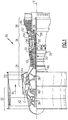
- FIG 1 schematically illustrates a gas turbine engine 20.
- the gas turbine engine 20 is disclosed herein as a two-spool turbofan that generally incorporates a fan section 22, a compressor section 24, a combustor section 26 and a turbine section 28.
- Alternative engines might include an augmentor section (not shown) among other systems or features.
- the fan section 22 drives air along a bypass flowpath B while the compressor section 24 drives air along a core flowpath C (as shown in Figure 2 ) for compression and communication into the combustor section 26 then expansion through the turbine section 28.
- a core flowpath C as shown in Figure 2
- the concepts described herein are not limited to use with two-spool turbofans as the teachings may be applied to other types of turbine engines including three-spool architectures.
- the exemplary engine 20 generally includes a low speed spool 30 and a high speed spool 32 mounted for rotation about an engine central longitudinal axis A relative to an engine static structure 36 via several bearing systems 38. It should be understood that various bearing systems 38 at various locations may alternatively or additionally be provided, and the location of bearing systems 38 may be varied as appropriate to the application.
- the low speed spool 30 generally includes an inner shaft 40 that interconnects a fan 42, a low pressure compressor 44 and a low pressure turbine 46.
- the inner shaft 40 is connected to the fan 42 through a speed change mechanism, which in exemplary gas turbine engine 20 is illustrated as a geared architecture 48 to drive the fan 42 at a lower speed than the low speed spool 30.
- the high speed spool 32 includes an outer shaft 50 that interconnects a high pressure compressor 52 and high pressure turbine 54.
- a combustor 56 is arranged in exemplary gas turbine 20 between the high pressure compressor 52 and the high pressure turbine 54.
- a mid-turbine frame 57 of the engine static structure 36 is arranged generally between the high pressure turbine 54 and the low pressure turbine 46.
- the mid-turbine frame 57 supports one or more bearing systems 38 in the turbine section 28.
- the inner shaft 40 and the outer shaft 50 are concentric and rotate via bearing systems 38 about the engine central longitudinal axis A, which is collinear with their longitudinal axes.
- the core airflow C is compressed by the low pressure compressor 44 then the high pressure compressor 52, mixed and burned with fuel in the combustor 56, then expanded over the high pressure turbine 54 and low pressure turbine 46.
- the mid-turbine frame 57 includes airfoils 59 which are in the core airflow path.
- the turbines 46, 54 rotationally drive the respective low speed spool 30 and high speed spool 32 in response to the expansion.
- gear system 48 may be located aft of combustor section 26 or even aft of turbine section 28, and fan section 22 may be positioned forward or aft of the location of gear system 48.
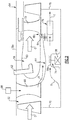
- the combustor section 26 includes a combustor 56 having a combustor housing 60.
- An injector 62 is arranged at a forward end of the combustor housing 60 and is configured to provide fuel to the combustor housing 60 where it is ignited to produce hot gases that expand through the turbine section 54.
- a diffuser case 64 is secured to the combustor housing 60 and forms a diffuser plenum surrounding the combustor housing 60.
- the diffuser plenum may receive a diffuser flow D for diffusing flow from the compressor section 52 into the combustor section 56.
- the diffuser case 64 and the combustor housing 60 are fixed relative to the engine static structure 36 ( Figure 1 ), illustrated as elements 36a and 36b in Figure 2 .
- an array of vanes 72 of a first stage of turbine stator vanes includes an inner portion that is partially supported by the diffuser case 64.
- One typical mounting method for first stage turbine vanes is to provide a radially inwardly extending flange 84 that includes a hole 86 (shown in Figure 4A ).
- a pin (not shown) is received in the hole to secure the flange 84 at a joint 88 (shown in Figure 2 ).
- the diffuser case 64 includes a portion arranged downstream from the compressor section 52 and upstream from the combustor section 26 that is sometimes referred to as a "pre-diffuser" 66.
- a bleed source 68 such as fluid from a compressor stage, provides cooling fluid through the pre-diffuser 66 to various locations interiorly of the diffuser case 64.
- a heat exchanger (not shown) may be used to cool the cooling fluid before entering the pre-diffuser 66.
- the compressor section 52 includes a compressor rotor 70 supported for rotation relative to the engine static structure 36b by the bearing 38.
- the bearing 38 is arranged within a bearing compartment 74 that is buffered using a buffer flow R.
- the turbine section 54 includes a turbine rotor 76 arranged downstream from a tangential on-board injector module 78, or "TOBI.”
- the TOBI 78 provides cooling flow T to the turbine rotor 76.
- the vanes 72 include an outer portion that is supported by the engine static structure 36a using a vane support 92, which is provided by a unitary annular structure, however, it should be understood that the vane support 92 may instead be constructed from multiple segments.
- the vane support 92 is grounded to an outer case of the engine static structure using teeth 93.
- the vanes 72 may be provided as multiple arcuate segments.
- each vane 72 is provided a doublet having a pair of airfoils joined between radially spaced apart inner and outer platforms 80, 82.
- the outer platform 82 includes radially extending circumferentially spaced structures providing a fork 90 that defines a notch 85.
- the vane support 92 includes a radially inwardly extending tab 94 that is received circumferentially within the fork 90 in the notch 85 to provide a circumferential load transfer assembly.
- at least one fork is provided on each vane. This fork and tab arrangement circumferentially locates the vanes 72 and transfers the circumferential load from the vanes 72 during engine operation to the engine static structure 36a via the vane support 92.
- the tab 94 includes a hole 96 to which a retainer 108 is secured to provide a retaining assembly.
- a retainer 108 is secured to provide a retaining assembly.
- up to twenty retaining assemblies may be provided circumferentially, which may be less than the number of vanes 72. The retaining assembly clamps the combustor housing 60 to the vane 72 and holds the assembly together, in particular, during compressor surge conditions.
- a ring seal 98 is arranged axially between an aft end of the combustor housing 60 and a forward face 100 of the outer platform 82.
- An edge 104 of the combustor housing 60 urges a sealing face 102 of the ring seal 98 into engagement with the forward face 100.
- a radially inwardly extending finger 110 of the retainer 108 engages an annular protrusion 106 that extends radially outwardly from the combustor housing 60.
- a fastener 114 received in the hole 96 and a hole 112 in the retainer 108 is used to apply a clamping load to seal the combustor 60 relative to the vane 72.
- vanes 172 ( Figure 3A ) that do not have a retaining assembly, for example, tabs 194, which without a hole 95 to accommodate the retainer 108, the fork 190 and its notch 185 may be narrower since there is no need to accommodate a fastener through the tab.
- FIG. 7A-7B Another example retainer 208 is illustrated in Figure 7A-7B .
- the retainer 208 may be a continuous annular ring or arcuate segments that provide multiple of fingers 210.
- Lightning holes 118 may be provided on the ring to reduce the weight of the retainer 208.
- the retaining assembly is secured to the circumferential load transfer assembly. Integrating the retaining assembly with the circumferential load transfer assembly provides a significant weight savings.
- the disclosed arrangement uses a single bolted on feature at several circumferential locations, which prevents circumferential movement of the vanes and prevents the combustor from moving forward in a surge condition.
Landscapes
- Engineering & Computer Science (AREA)
- Mechanical Engineering (AREA)
- General Engineering & Computer Science (AREA)
- Chemical & Material Sciences (AREA)
- Combustion & Propulsion (AREA)
- Turbine Rotor Nozzle Sealing (AREA)
- Structures Of Non-Positive Displacement Pumps (AREA)
Abstract
Description
- This application claims priority to United States Provisional Application No.
61/875,997, which was filed on September 10, 2013 - This invention was made with government support under Contract No. FA8650-09-D-29230021 awarded by the United States Air Force. The Government has certain rights in this invention.
- This disclosure relates to first stage turbine vanes and associated mounting arrangement.
- A gas turbine engine typically includes a fan section, a compressor section, a combustor section and a turbine section. Core flow air entering the compressor section is compressed and delivered into the combustion section where it is mixed with fuel and ignited to generate a high-speed exhaust gas flow. The combustor section includes a combustor housing with a flange used to mount the combustor housing with respect to the engine's static structure. The high-speed exhaust gas flow expands through the turbine section to drive the compressor and the fan section.
- First stage turbine vanes are arranged immediately downstream from the combustor section to efficiently communicate the core flow into the first stage of turbine blades. Prior technology for the first stage turbine vanes employs two separate features to complete two separate tasks, affixing the vanes circumferentially and supporting the combustor in the event of a compressor surge condition.
- Typically an array of separate vanes or clusters of vanes are mounted with respect to the engines static structure. The engine static structure includes a circumferential load transfer assembly having a circumferential array of tabs, which are used to interface with a fork on each of the first vanes to affix the vanes circumferentially. The engine static structure also includes a boss separate from the tabs to which a retainer is bolted to provide a retaining assembly. The retaining assembly secures the combustor flange to the engine static structure via the vanes and holds the flange in place in case of a compressor surge condition. These two features are separate from one another and located circumferentially between each other around the engine static structure.
- In one exemplary embodiment, a gas turbine engine includes a vane and a combustor housing that are supported relative to an engine static structure. A retaining assembly clamps the combustor housing and the vane to one another in an axial direction. A circumferential load transfer assembly circumferentially affixes the vane relative to the engine static structure. The retaining assembly is secured to the circumferential load transfer assembly.
- In a further embodiment of the above, the engine static structure includes a vane support. The vane support includes one of a tab and a fork. The vane includes the other of the tab and the fork. The tab is received in the fork. The tab and the fork provide the circumferential load transfer assembly.
- In a further embodiment of any of the above, the fork is provided on an outer platform of the vane. The tab is provided on the vane support.
- In a further embodiment of any of the above, the retainer assembly includes a retainer secured to the tab. The combustor housing is arranged axially between the retainer and the vane.
- In a further embodiment of any of the above, a seal ring is engaged between the combustor housing and the vane.
- In a further embodiment of any of the above, the retainer includes a finger. The combustor housing includes an annular protrusion that extends radially outward from the combustor housing. The finger engages the annular protrusion.
- In a further embodiment of any of the above, the combustor housing includes an edge that engages the seal ring.
- In a further embodiment of any of the above, the retainer and tab include holes. A fastener extends through the holes to secure the retainer to the vane support.
- In a further embodiment of any of the above, there is a circumferential array of a number of vanes. Each vane includes a fork and a number of tabs with holes being less than the number of vanes.
- In a further embodiment of any of the above, the retaining assembly is provided by discrete retainers circumferentially spaced from one another.
- In a further embodiment of any of the above, the retaining assembly is provided by an annular ring that is secured to multiple tabs.
- In a further embodiment of any of the above, the annular ring includes lightening holes.
- In another exemplary embodiment, a gas turbine engine includes an engine static structure that includes a vane support having a tab. A vane includes a fork that has a notch that receives the tab to circumferentially affix the vane to the engine static structure. A retainer is secured to the tab and mounts a combustor housing to the vane in an axial direction.
- In a further embodiment of the above, a seal ring is engaged between the combustor housing and the vane.
- In a further embodiment of any of the above, the retainer includes a finger. The combustor housing includes an annular protrusion that extends radially outward from the combustor housing. The finger engages the annular protrusion.
- In a further embodiment of any of the above, the combustor housing includes an edge that engages the seal ring.
- In a further embodiment of any of the above, the retainer and tab include holes. A fastener extends through the holes to secure the retainer to the vane support.
- In a further embodiment of any of the above, there is a circumferential array of a number of vanes. Each vane includes a fork and a number of tabs with holes being less than the number of vanes.
- In a further embodiment of any of the above, discrete retainers are circumferentially spaced from one another.
- In a further embodiment of any of the above, the retainer is provided by an annular ring secured to multiple tabs.
- The disclosure can be further understood by reference to the following detailed description when considered in connection with the accompanying drawings wherein:
-
Figure 1 is a schematic view of an example gas turbine engine including a combustor section. -
Figure 2 is a schematic view of the combustor section. -
Figure 3A illustrates an example first stage turbine vane supported relative to engine static structure, which includes a vane support. -
Figure 3B is a cross-sectional view of the assembly shown infigure 3A and taken alongline 3B-3B. -
Figure 4A is a front elevational view of an example turbine vane shown inFigure 3A . -
Figure 4B is an enlarged view of the vane support shown inFigure 3A . -
Figure 5 is a cross-sectional view of a retainer assembly used to support a combustor housing and the turbine vanes relative to the engine static structure. -
Figure 6 is a front elevational view of an example retainer. -
Figure 7A is a front elevational view of another example retainer. -
Figure 7B is a cross-sectional view of the retainer shown inFigure 7A and taken alongline 7B-7B. -
Figure 1 schematically illustrates agas turbine engine 20. Although commercial engine embodiment is shown, the disclosed vane mounting arrangement may also be used in military engine applications. Thegas turbine engine 20 is disclosed herein as a two-spool turbofan that generally incorporates afan section 22, acompressor section 24, acombustor section 26 and aturbine section 28. Alternative engines might include an augmentor section (not shown) among other systems or features. - The
fan section 22 drives air along a bypass flowpath B while thecompressor section 24 drives air along a core flowpath C (as shown inFigure 2 ) for compression and communication into thecombustor section 26 then expansion through theturbine section 28. Although depicted as a two-spool turbofan gas turbine engine in the disclosed non-limiting embodiment, it should be understood that the concepts described herein are not limited to use with two-spool turbofans as the teachings may be applied to other types of turbine engines including three-spool architectures. - The
exemplary engine 20 generally includes alow speed spool 30 and ahigh speed spool 32 mounted for rotation about an engine central longitudinal axis A relative to an enginestatic structure 36 viaseveral bearing systems 38. It should be understood that various bearingsystems 38 at various locations may alternatively or additionally be provided, and the location of bearingsystems 38 may be varied as appropriate to the application. - The
low speed spool 30 generally includes aninner shaft 40 that interconnects afan 42, alow pressure compressor 44 and alow pressure turbine 46. Theinner shaft 40 is connected to thefan 42 through a speed change mechanism, which in exemplarygas turbine engine 20 is illustrated as a gearedarchitecture 48 to drive thefan 42 at a lower speed than thelow speed spool 30. Thehigh speed spool 32 includes anouter shaft 50 that interconnects ahigh pressure compressor 52 andhigh pressure turbine 54. Acombustor 56 is arranged inexemplary gas turbine 20 between thehigh pressure compressor 52 and thehigh pressure turbine 54. Amid-turbine frame 57 of the enginestatic structure 36 is arranged generally between thehigh pressure turbine 54 and thelow pressure turbine 46. Themid-turbine frame 57 supports one ormore bearing systems 38 in theturbine section 28. Theinner shaft 40 and theouter shaft 50 are concentric and rotate via bearingsystems 38 about the engine central longitudinal axis A, which is collinear with their longitudinal axes. - The core airflow C is compressed by the
low pressure compressor 44 then thehigh pressure compressor 52, mixed and burned with fuel in thecombustor 56, then expanded over thehigh pressure turbine 54 andlow pressure turbine 46. Themid-turbine frame 57 includesairfoils 59 which are in the core airflow path. Theturbines low speed spool 30 andhigh speed spool 32 in response to the expansion. It will be appreciated that each of the positions of thefan section 22,compressor section 24,combustor section 26,turbine section 28, and fandrive gear system 48 may be varied. For example,gear system 48 may be located aft ofcombustor section 26 or even aft ofturbine section 28, andfan section 22 may be positioned forward or aft of the location ofgear system 48. - An area of the
combustor section 26 is shown in more detail inFigure 2 . Thecombustor section 26 includes acombustor 56 having acombustor housing 60. Aninjector 62 is arranged at a forward end of thecombustor housing 60 and is configured to provide fuel to thecombustor housing 60 where it is ignited to produce hot gases that expand through theturbine section 54. - A
diffuser case 64 is secured to thecombustor housing 60 and forms a diffuser plenum surrounding thecombustor housing 60. The diffuser plenum may receive a diffuser flow D for diffusing flow from thecompressor section 52 into thecombustor section 56. Thediffuser case 64 and thecombustor housing 60 are fixed relative to the engine static structure 36 (Figure 1 ), illustrated aselements Figure 2 . - In one example, an array of
vanes 72 of a first stage of turbine stator vanes includes an inner portion that is partially supported by thediffuser case 64. One typical mounting method for first stage turbine vanes is to provide a radially inwardly extendingflange 84 that includes a hole 86 (shown inFigure 4A ). A pin (not shown) is received in the hole to secure theflange 84 at a joint 88 (shown inFigure 2 ). - With continuing reference to
Figure 2 , thediffuser case 64 includes a portion arranged downstream from thecompressor section 52 and upstream from thecombustor section 26 that is sometimes referred to as a "pre-diffuser" 66. Ableed source 68, such as fluid from a compressor stage, provides cooling fluid through the pre-diffuser 66 to various locations interiorly of thediffuser case 64. A heat exchanger (not shown) may be used to cool the cooling fluid before entering the pre-diffuser 66. - The
compressor section 52 includes acompressor rotor 70 supported for rotation relative to the enginestatic structure 36b by thebearing 38. Thebearing 38 is arranged within abearing compartment 74 that is buffered using a buffer flow R. Theturbine section 54 includes aturbine rotor 76 arranged downstream from a tangential on-board injector module 78, or "TOBI." TheTOBI 78 provides cooling flow T to theturbine rotor 76. - Referring to
Figures 3A-4B , thevanes 72 include an outer portion that is supported by the enginestatic structure 36a using avane support 92, which is provided by a unitary annular structure, however, it should be understood that thevane support 92 may instead be constructed from multiple segments. In one example, thevane support 92 is grounded to an outer case of the engine staticstructure using teeth 93. Thevanes 72 may be provided as multiple arcuate segments. In one example, eachvane 72 is provided a doublet having a pair of airfoils joined between radially spaced apart inner andouter platforms - The
outer platform 82 includes radially extending circumferentially spaced structures providing afork 90 that defines anotch 85. Thevane support 92 includes a radially inwardly extendingtab 94 that is received circumferentially within thefork 90 in thenotch 85 to provide a circumferential load transfer assembly. In one example, at least one fork is provided on each vane. This fork and tab arrangement circumferentially locates thevanes 72 and transfers the circumferential load from thevanes 72 during engine operation to the enginestatic structure 36a via thevane support 92. - Referring to
Figures 5 and 6 , thetab 94 includes ahole 96 to which aretainer 108 is secured to provide a retaining assembly. In one example, up to twenty retaining assemblies may be provided circumferentially, which may be less than the number ofvanes 72. The retaining assembly clamps thecombustor housing 60 to thevane 72 and holds the assembly together, in particular, during compressor surge conditions. - In one example, a
ring seal 98 is arranged axially between an aft end of thecombustor housing 60 and aforward face 100 of theouter platform 82. Anedge 104 of thecombustor housing 60 urges a sealingface 102 of thering seal 98 into engagement with theforward face 100. A radially inwardly extendingfinger 110 of theretainer 108 engages anannular protrusion 106 that extends radially outwardly from thecombustor housing 60. Afastener 114 received in thehole 96 and ahole 112 in theretainer 108 is used to apply a clamping load to seal thecombustor 60 relative to thevane 72. - For vanes 172 (
Figure 3A ) that do not have a retaining assembly, for example,tabs 194, which without a hole 95 to accommodate theretainer 108, the fork 190 and itsnotch 185 may be narrower since there is no need to accommodate a fastener through the tab. - Another
example retainer 208 is illustrated inFigure 7A-7B . Unlike thediscrete retainer 108 illustrated inFigures 5 and 6 , theretainer 208 may be a continuous annular ring or arcuate segments that provide multiple offingers 210. Lightning holes 118 may be provided on the ring to reduce the weight of theretainer 208. - The retaining assembly is secured to the circumferential load transfer assembly. Integrating the retaining assembly with the circumferential load transfer assembly provides a significant weight savings. The disclosed arrangement uses a single bolted on feature at several circumferential locations, which prevents circumferential movement of the vanes and prevents the combustor from moving forward in a surge condition.
- It should also be understood that although a particular component arrangement is disclosed in the illustrated embodiment, other arrangements will benefit herefrom. Although particular step sequences are shown, described, and claimed, it should be understood that steps may be performed in any order, separated or combined unless otherwise indicated and will still benefit from the present invention.
- Although the different examples have specific components shown in the illustrations, embodiments of this invention are not limited to those particular combinations. It is possible to use some of the components or features from one of the examples in combination with features or components from another one of the examples.
- Although an example embodiment has been disclosed, a worker of ordinary skill in this art would recognize that certain modifications would come within the scope of the claims. For that reason, the following claims should be studied to determine their true scope and content.
Claims (13)
- A gas turbine engine (20) comprising:a vane (72; 172) and a combustor housing (60) supported relative to an engine static structure (36);a retaining assembly clamping the combustor housing (60) and the vane (72; 172) to one another in an axial direction; anda circumferential load transfer assembly circumferentially affixing the vane (72; 172) relative to the engine static structure (36), the retaining assembly secured to the circumferential load transfer assembly.
- The gas turbine engine according to claim 1, wherein the engine static structure (36) includes a vane support (92), the vane support (92) including one of a tab (94; 194) and a fork (90; 190), and the vane (72; 172) including the other of the tab (94; 194) and the fork (90; 190), the tab (94; 194) received in the fork (90; 190), and the tab (94; 194) and the fork (90; 190) providing the circumferential load transfer assembly.
- The gas turbine engine according to claim 2, wherein the fork (90) is provided on an outer platform (82) of the vane (72), and the tab (94) is provided on the vane support (92).
- The gas turbine engine according to claim 2 or 3, wherein the retainer assembly includes a retainer (108; 208) secured to the tab (94), and the combustor housing (60) arranged axially between the retainer (108) and the vane (72).
- A gas turbine engine (20) comprising:an engine static structure (36) include a vane support having a tab (194);a vane (172) including a fork (190) having a notch (185) receiving the tab to circumferentially affix the vane (172) to the engine static structure (36); anda retainer (108; 208) secured to the tab (194) and mounting a combustor housing (60) to the vane (72) in an axial direction.
- The gas turbine engine according to claim 4 or 5, comprising a seal ring (98) engaged between the combustor housing (60) and the vane (72; 172).
- The gas turbine engine according to claim 6, wherein the retainer (108; 208) includes a finger (110; 210), the combustor housing (60) includes an annular protrusion (106) extending radially outward from the combustor housing (60), the finger (110; 210) engaging the annular protrusion (60).
- The gas turbine engine according to claim 7, wherein the combustor housing (60) includes an edge (104) engaging the seal ring (98).
- The gas turbine engine according to any of claims 4 to 8, wherein the retainer (108) and tab (94) include holes (110, 96), and a fastener (114) extends through the holes to secure the retainer (108) to the vane support (92).
- The gas turbine engine according to claim 9, comprising a circumferential array of a number of vanes (172), each vane (172) including a fork (190), and a number of tabs (194) with holes being less than the number of vanes (172).
- The gas turbine engine according to any of claims 4 to 10, wherein the retaining assembly is provided by discrete retainers (108) circumferentially spaced from one another.
- The gas turbine engine according to any of claims 4 to 10, wherein the retaining assembly is provided by an annular ring (208) secured to multiple tabs.
- The gas turbine engine according to claim 12, wherein the annular ring (208) includes lightening holes (118).
Applications Claiming Priority (3)
| Application Number | Priority Date | Filing Date | Title |
|---|---|---|---|
| US201361875997P | 2013-09-10 | 2013-09-10 | |
| PCT/US2014/053807 WO2015076896A2 (en) | 2013-09-10 | 2014-09-03 | Dual anti surge and anti rotation feature on first vane support |
| EP14863615.2A EP3044421B1 (en) | 2013-09-10 | 2014-09-03 | Dual anti surge and anti rotation feature on first vane support |
Related Parent Applications (2)
| Application Number | Title | Priority Date | Filing Date |
|---|---|---|---|
| EP14863615.2A Division EP3044421B1 (en) | 2013-09-10 | 2014-09-03 | Dual anti surge and anti rotation feature on first vane support |
| EP14863615.2A Division-Into EP3044421B1 (en) | 2013-09-10 | 2014-09-03 | Dual anti surge and anti rotation feature on first vane support |
Publications (2)
| Publication Number | Publication Date |
|---|---|
| EP3299583A1 true EP3299583A1 (en) | 2018-03-28 |
| EP3299583B1 EP3299583B1 (en) | 2019-10-30 |
Family
ID=53180361
Family Applications (2)
| Application Number | Title | Priority Date | Filing Date |
|---|---|---|---|
| EP17201018.3A Active EP3299583B1 (en) | 2013-09-10 | 2014-09-03 | Dual anti surge and anti rotation feature on first vane support |
| EP14863615.2A Active EP3044421B1 (en) | 2013-09-10 | 2014-09-03 | Dual anti surge and anti rotation feature on first vane support |
Family Applications After (1)
| Application Number | Title | Priority Date | Filing Date |
|---|---|---|---|
| EP14863615.2A Active EP3044421B1 (en) | 2013-09-10 | 2014-09-03 | Dual anti surge and anti rotation feature on first vane support |
Country Status (3)
| Country | Link |
|---|---|
| US (1) | US10337354B2 (en) |
| EP (2) | EP3299583B1 (en) |
| WO (1) | WO2015076896A2 (en) |
Families Citing this family (3)
| Publication number | Priority date | Publication date | Assignee | Title |
|---|---|---|---|---|
| JP5886465B1 (en) * | 2015-09-08 | 2016-03-16 | 三菱日立パワーシステムズ株式会社 | SEAL MEMBER ASSEMBLY STRUCTURE AND ASSEMBLY METHOD, SEAL MEMBER, GAS TURBINE |
| US20180017260A1 (en) * | 2016-07-14 | 2018-01-18 | United Technologies Corporation | Combustor anti-surge retention system |
| JP6737969B1 (en) * | 2020-02-18 | 2020-08-12 | 三菱日立パワーシステムズ株式会社 | Outlet seal and gas turbine including the same |
Citations (2)
| Publication number | Priority date | Publication date | Assignee | Title |
|---|---|---|---|---|
| US7237388B2 (en) * | 2004-06-17 | 2007-07-03 | Snecma | Assembly comprising a gas turbine combustion chamber integrated with a high pressure turbine nozzle |
| US20080008584A1 (en) * | 2006-07-06 | 2008-01-10 | Siemens Power Generation, Inc. | Cantilevered framework support for turbine vane |
Family Cites Families (11)
| Publication number | Priority date | Publication date | Assignee | Title |
|---|---|---|---|---|
| US4016718A (en) * | 1975-07-21 | 1977-04-12 | United Technologies Corporation | Gas turbine engine having an improved transition duct support |
| US4566851A (en) * | 1984-05-11 | 1986-01-28 | United Technologies Corporation | First stage turbine vane support structure |
| US4697981A (en) * | 1984-12-13 | 1987-10-06 | United Technologies Corporation | Rotor thrust balancing |
| US4785623A (en) | 1987-12-09 | 1988-11-22 | United Technologies Corporation | Combustor seal and support |
| US5289677A (en) | 1992-12-16 | 1994-03-01 | United Technologies Corporation | Combined support and seal ring for a combustor |
| US5785492A (en) | 1997-03-24 | 1998-07-28 | United Technologies Corporation | Method and apparatus for sealing a gas turbine stator vane assembly |
| US6347508B1 (en) * | 2000-03-22 | 2002-02-19 | Allison Advanced Development Company | Combustor liner support and seal assembly |
| US8033786B2 (en) * | 2007-12-12 | 2011-10-11 | Pratt & Whitney Canada Corp. | Axial loading element for turbine vane |
| US8133019B2 (en) * | 2009-01-21 | 2012-03-13 | General Electric Company | Discrete load fins for individual stator vanes |
| US8206096B2 (en) | 2009-07-08 | 2012-06-26 | General Electric Company | Composite turbine nozzle |
| GB201200237D0 (en) * | 2012-01-09 | 2012-02-22 | Rolls Royce Plc | A combustor for a gas turbine engine |
-
2014
- 2014-09-03 EP EP17201018.3A patent/EP3299583B1/en active Active
- 2014-09-03 EP EP14863615.2A patent/EP3044421B1/en active Active
- 2014-09-03 WO PCT/US2014/053807 patent/WO2015076896A2/en not_active Ceased
- 2014-09-03 US US14/915,755 patent/US10337354B2/en active Active
Patent Citations (2)
| Publication number | Priority date | Publication date | Assignee | Title |
|---|---|---|---|---|
| US7237388B2 (en) * | 2004-06-17 | 2007-07-03 | Snecma | Assembly comprising a gas turbine combustion chamber integrated with a high pressure turbine nozzle |
| US20080008584A1 (en) * | 2006-07-06 | 2008-01-10 | Siemens Power Generation, Inc. | Cantilevered framework support for turbine vane |
Also Published As
| Publication number | Publication date |
|---|---|
| WO2015076896A3 (en) | 2015-08-06 |
| EP3044421A4 (en) | 2016-10-12 |
| EP3044421A2 (en) | 2016-07-20 |
| EP3299583B1 (en) | 2019-10-30 |
| WO2015076896A2 (en) | 2015-05-28 |
| US20160194981A1 (en) | 2016-07-07 |
| US10337354B2 (en) | 2019-07-02 |
| EP3044421B1 (en) | 2018-05-02 |
Similar Documents
| Publication | Publication Date | Title |
|---|---|---|
| US10221711B2 (en) | Integrated strut and vane arrangements | |
| EP2900956B1 (en) | Gas turbine engine comprising a seal assembly for a static structure thereof | |
| US9879558B2 (en) | Low leakage multi-directional interface for a gas turbine engine | |
| EP3093445B1 (en) | Gas turbine vane and method of forming | |
| EP2855892B1 (en) | Mid-turbine frame for a gas turbine engine comprising a seal land | |
| US20160090841A1 (en) | Gas turbine engine blade slot heat shield | |
| US20140223920A1 (en) | Consumable assembly mistake proofing tool for a gas turbine engine | |
| US9970311B2 (en) | Consumable assembly tool for a gas turbine engine | |
| EP3071794A1 (en) | Multi-element inner shroud extension for a turbo-machine | |
| EP2900942B1 (en) | Mid-turbine frame heat shield | |
| EP3044421B1 (en) | Dual anti surge and anti rotation feature on first vane support | |
| EP3708773B1 (en) | Gas turbine engine comprising a seal for a rotor stack and corresponding method of sealing a shaft relatively to a rotor disk | |
| EP3047110B1 (en) | Flow splitting first vane support for gas turbine engine and method of flowing fluid through a gas turbine engine | |
| US9777634B2 (en) | Tube fed tangential on-board injector for gas turbine engine | |
| EP3102808B1 (en) | Gas turbine engine with cooling fluid composite tube | |
| EP3282101B1 (en) | Shim for gas turbine engine | |
| EP3564495B1 (en) | Gas turbine engine exhaust component | |
| EP3098387B1 (en) | Installation fault tolerant damper | |
| US11199104B2 (en) | Seal anti-rotation | |
| EP3011155B1 (en) | Heat shield |
Legal Events
| Date | Code | Title | Description |
|---|---|---|---|
| PUAI | Public reference made under article 153(3) epc to a published international application that has entered the european phase |
Free format text: ORIGINAL CODE: 0009012 |
|
| STAA | Information on the status of an ep patent application or granted ep patent |
Free format text: STATUS: THE APPLICATION HAS BEEN PUBLISHED |
|
| AC | Divisional application: reference to earlier application |
Ref document number: 3044421 Country of ref document: EP Kind code of ref document: P |
|
| AK | Designated contracting states |
Kind code of ref document: A1 Designated state(s): AL AT BE BG CH CY CZ DE DK EE ES FI FR GB GR HR HU IE IS IT LI LT LU LV MC MK MT NL NO PL PT RO RS SE SI SK SM TR |
|
| STAA | Information on the status of an ep patent application or granted ep patent |
Free format text: STATUS: REQUEST FOR EXAMINATION WAS MADE |
|
| 17P | Request for examination filed |
Effective date: 20180928 |
|
| RBV | Designated contracting states (corrected) |
Designated state(s): AL AT BE BG CH CY CZ DE DK EE ES FI FR GB GR HR HU IE IS IT LI LT LU LV MC MK MT NL NO PL PT RO RS SE SI SK SM TR |
|
| GRAP | Despatch of communication of intention to grant a patent |
Free format text: ORIGINAL CODE: EPIDOSNIGR1 |
|
| STAA | Information on the status of an ep patent application or granted ep patent |
Free format text: STATUS: GRANT OF PATENT IS INTENDED |
|
| RIC1 | Information provided on ipc code assigned before grant |
Ipc: F01D 25/28 20060101ALI20190308BHEP Ipc: F01D 25/24 20060101ALI20190308BHEP Ipc: F01D 11/00 20060101ALI20190308BHEP Ipc: F02C 7/20 20060101ALI20190308BHEP Ipc: F01D 9/02 20060101AFI20190308BHEP Ipc: F23R 3/00 20060101ALI20190308BHEP Ipc: F01D 9/04 20060101ALI20190308BHEP |
|
| INTG | Intention to grant announced |
Effective date: 20190417 |
|
| GRAS | Grant fee paid |
Free format text: ORIGINAL CODE: EPIDOSNIGR3 |
|
| GRAA | (expected) grant |
Free format text: ORIGINAL CODE: 0009210 |
|
| STAA | Information on the status of an ep patent application or granted ep patent |
Free format text: STATUS: THE PATENT HAS BEEN GRANTED |
|
| AC | Divisional application: reference to earlier application |
Ref document number: 3044421 Country of ref document: EP Kind code of ref document: P |
|
| AK | Designated contracting states |
Kind code of ref document: B1 Designated state(s): AL AT BE BG CH CY CZ DE DK EE ES FI FR GB GR HR HU IE IS IT LI LT LU LV MC MK MT NL NO PL PT RO RS SE SI SK SM TR |
|
| REG | Reference to a national code |
Ref country code: GB Ref legal event code: FG4D |
|
| REG | Reference to a national code |
Ref country code: CH Ref legal event code: EP |
|
| REG | Reference to a national code |
Ref country code: AT Ref legal event code: REF Ref document number: 1196355 Country of ref document: AT Kind code of ref document: T Effective date: 20191115 |
|
| REG | Reference to a national code |
Ref country code: DE Ref legal event code: R096 Ref document number: 602014056147 Country of ref document: DE |
|
| REG | Reference to a national code |
Ref country code: IE Ref legal event code: FG4D |
|
| REG | Reference to a national code |
Ref country code: LT Ref legal event code: MG4D |
|
| PG25 | Lapsed in a contracting state [announced via postgrant information from national office to epo] |
Ref country code: PT Free format text: LAPSE BECAUSE OF FAILURE TO SUBMIT A TRANSLATION OF THE DESCRIPTION OR TO PAY THE FEE WITHIN THE PRESCRIBED TIME-LIMIT Effective date: 20200302 Ref country code: FI Free format text: LAPSE BECAUSE OF FAILURE TO SUBMIT A TRANSLATION OF THE DESCRIPTION OR TO PAY THE FEE WITHIN THE PRESCRIBED TIME-LIMIT Effective date: 20191030 Ref country code: BG Free format text: LAPSE BECAUSE OF FAILURE TO SUBMIT A TRANSLATION OF THE DESCRIPTION OR TO PAY THE FEE WITHIN THE PRESCRIBED TIME-LIMIT Effective date: 20200130 Ref country code: NO Free format text: LAPSE BECAUSE OF FAILURE TO SUBMIT A TRANSLATION OF THE DESCRIPTION OR TO PAY THE FEE WITHIN THE PRESCRIBED TIME-LIMIT Effective date: 20200130 Ref country code: SE Free format text: LAPSE BECAUSE OF FAILURE TO SUBMIT A TRANSLATION OF THE DESCRIPTION OR TO PAY THE FEE WITHIN THE PRESCRIBED TIME-LIMIT Effective date: 20191030 Ref country code: LV Free format text: LAPSE BECAUSE OF FAILURE TO SUBMIT A TRANSLATION OF THE DESCRIPTION OR TO PAY THE FEE WITHIN THE PRESCRIBED TIME-LIMIT Effective date: 20191030 Ref country code: NL Free format text: LAPSE BECAUSE OF FAILURE TO SUBMIT A TRANSLATION OF THE DESCRIPTION OR TO PAY THE FEE WITHIN THE PRESCRIBED TIME-LIMIT Effective date: 20191030 Ref country code: LT Free format text: LAPSE BECAUSE OF FAILURE TO SUBMIT A TRANSLATION OF THE DESCRIPTION OR TO PAY THE FEE WITHIN THE PRESCRIBED TIME-LIMIT Effective date: 20191030 Ref country code: GR Free format text: LAPSE BECAUSE OF FAILURE TO SUBMIT A TRANSLATION OF THE DESCRIPTION OR TO PAY THE FEE WITHIN THE PRESCRIBED TIME-LIMIT Effective date: 20200131 Ref country code: PL Free format text: LAPSE BECAUSE OF FAILURE TO SUBMIT A TRANSLATION OF THE DESCRIPTION OR TO PAY THE FEE WITHIN THE PRESCRIBED TIME-LIMIT Effective date: 20191030 |
|
| REG | Reference to a national code |
Ref country code: NL Ref legal event code: MP Effective date: 20191030 |
|
| PG25 | Lapsed in a contracting state [announced via postgrant information from national office to epo] |
Ref country code: HR Free format text: LAPSE BECAUSE OF FAILURE TO SUBMIT A TRANSLATION OF THE DESCRIPTION OR TO PAY THE FEE WITHIN THE PRESCRIBED TIME-LIMIT Effective date: 20191030 Ref country code: IS Free format text: LAPSE BECAUSE OF FAILURE TO SUBMIT A TRANSLATION OF THE DESCRIPTION OR TO PAY THE FEE WITHIN THE PRESCRIBED TIME-LIMIT Effective date: 20200229 Ref country code: RS Free format text: LAPSE BECAUSE OF FAILURE TO SUBMIT A TRANSLATION OF THE DESCRIPTION OR TO PAY THE FEE WITHIN THE PRESCRIBED TIME-LIMIT Effective date: 20191030 |
|
| PG25 | Lapsed in a contracting state [announced via postgrant information from national office to epo] |
Ref country code: AL Free format text: LAPSE BECAUSE OF FAILURE TO SUBMIT A TRANSLATION OF THE DESCRIPTION OR TO PAY THE FEE WITHIN THE PRESCRIBED TIME-LIMIT Effective date: 20191030 |
|
| PG25 | Lapsed in a contracting state [announced via postgrant information from national office to epo] |
Ref country code: DK Free format text: LAPSE BECAUSE OF FAILURE TO SUBMIT A TRANSLATION OF THE DESCRIPTION OR TO PAY THE FEE WITHIN THE PRESCRIBED TIME-LIMIT Effective date: 20191030 Ref country code: RO Free format text: LAPSE BECAUSE OF FAILURE TO SUBMIT A TRANSLATION OF THE DESCRIPTION OR TO PAY THE FEE WITHIN THE PRESCRIBED TIME-LIMIT Effective date: 20191030 Ref country code: EE Free format text: LAPSE BECAUSE OF FAILURE TO SUBMIT A TRANSLATION OF THE DESCRIPTION OR TO PAY THE FEE WITHIN THE PRESCRIBED TIME-LIMIT Effective date: 20191030 Ref country code: ES Free format text: LAPSE BECAUSE OF FAILURE TO SUBMIT A TRANSLATION OF THE DESCRIPTION OR TO PAY THE FEE WITHIN THE PRESCRIBED TIME-LIMIT Effective date: 20191030 Ref country code: CZ Free format text: LAPSE BECAUSE OF FAILURE TO SUBMIT A TRANSLATION OF THE DESCRIPTION OR TO PAY THE FEE WITHIN THE PRESCRIBED TIME-LIMIT Effective date: 20191030 |
|
| REG | Reference to a national code |
Ref country code: DE Ref legal event code: R097 Ref document number: 602014056147 Country of ref document: DE |
|
| REG | Reference to a national code |
Ref country code: AT Ref legal event code: MK05 Ref document number: 1196355 Country of ref document: AT Kind code of ref document: T Effective date: 20191030 |
|
| PG25 | Lapsed in a contracting state [announced via postgrant information from national office to epo] |
Ref country code: SM Free format text: LAPSE BECAUSE OF FAILURE TO SUBMIT A TRANSLATION OF THE DESCRIPTION OR TO PAY THE FEE WITHIN THE PRESCRIBED TIME-LIMIT Effective date: 20191030 Ref country code: IT Free format text: LAPSE BECAUSE OF FAILURE TO SUBMIT A TRANSLATION OF THE DESCRIPTION OR TO PAY THE FEE WITHIN THE PRESCRIBED TIME-LIMIT Effective date: 20191030 Ref country code: SK Free format text: LAPSE BECAUSE OF FAILURE TO SUBMIT A TRANSLATION OF THE DESCRIPTION OR TO PAY THE FEE WITHIN THE PRESCRIBED TIME-LIMIT Effective date: 20191030 |
|
| PLBE | No opposition filed within time limit |
Free format text: ORIGINAL CODE: 0009261 |
|
| STAA | Information on the status of an ep patent application or granted ep patent |
Free format text: STATUS: NO OPPOSITION FILED WITHIN TIME LIMIT |
|
| 26N | No opposition filed |
Effective date: 20200731 |
|
| PG25 | Lapsed in a contracting state [announced via postgrant information from national office to epo] |
Ref country code: AT Free format text: LAPSE BECAUSE OF FAILURE TO SUBMIT A TRANSLATION OF THE DESCRIPTION OR TO PAY THE FEE WITHIN THE PRESCRIBED TIME-LIMIT Effective date: 20191030 Ref country code: SI Free format text: LAPSE BECAUSE OF FAILURE TO SUBMIT A TRANSLATION OF THE DESCRIPTION OR TO PAY THE FEE WITHIN THE PRESCRIBED TIME-LIMIT Effective date: 20191030 |
|
| REG | Reference to a national code |
Ref country code: CH Ref legal event code: PL |
|
| REG | Reference to a national code |
Ref country code: BE Ref legal event code: MM Effective date: 20200930 |
|
| PG25 | Lapsed in a contracting state [announced via postgrant information from national office to epo] |
Ref country code: LU Free format text: LAPSE BECAUSE OF NON-PAYMENT OF DUE FEES Effective date: 20200903 |
|
| PG25 | Lapsed in a contracting state [announced via postgrant information from national office to epo] |
Ref country code: BE Free format text: LAPSE BECAUSE OF NON-PAYMENT OF DUE FEES Effective date: 20200930 Ref country code: CH Free format text: LAPSE BECAUSE OF NON-PAYMENT OF DUE FEES Effective date: 20200930 Ref country code: LI Free format text: LAPSE BECAUSE OF NON-PAYMENT OF DUE FEES Effective date: 20200930 Ref country code: IE Free format text: LAPSE BECAUSE OF NON-PAYMENT OF DUE FEES Effective date: 20200903 |
|
| PG25 | Lapsed in a contracting state [announced via postgrant information from national office to epo] |
Ref country code: TR Free format text: LAPSE BECAUSE OF FAILURE TO SUBMIT A TRANSLATION OF THE DESCRIPTION OR TO PAY THE FEE WITHIN THE PRESCRIBED TIME-LIMIT Effective date: 20191030 Ref country code: MT Free format text: LAPSE BECAUSE OF FAILURE TO SUBMIT A TRANSLATION OF THE DESCRIPTION OR TO PAY THE FEE WITHIN THE PRESCRIBED TIME-LIMIT Effective date: 20191030 Ref country code: CY Free format text: LAPSE BECAUSE OF FAILURE TO SUBMIT A TRANSLATION OF THE DESCRIPTION OR TO PAY THE FEE WITHIN THE PRESCRIBED TIME-LIMIT Effective date: 20191030 |
|
| PG25 | Lapsed in a contracting state [announced via postgrant information from national office to epo] |
Ref country code: MK Free format text: LAPSE BECAUSE OF FAILURE TO SUBMIT A TRANSLATION OF THE DESCRIPTION OR TO PAY THE FEE WITHIN THE PRESCRIBED TIME-LIMIT Effective date: 20191030 Ref country code: MC Free format text: LAPSE BECAUSE OF FAILURE TO SUBMIT A TRANSLATION OF THE DESCRIPTION OR TO PAY THE FEE WITHIN THE PRESCRIBED TIME-LIMIT Effective date: 20191030 |
|
| REG | Reference to a national code |
Ref country code: DE Ref legal event code: R081 Ref document number: 602014056147 Country of ref document: DE Owner name: RAYTHEON TECHNOLOGIES CORPORATION (N.D.GES.D.S, US Free format text: FORMER OWNER: UNITED TECHNOLOGIES CORPORATION, FARMINGTON, CONN., US Ref country code: DE Ref legal event code: R081 Ref document number: 602014056147 Country of ref document: DE Owner name: RTX CORPORATION (N.D.GES.D. STAATES DELAWARE),, US Free format text: FORMER OWNER: UNITED TECHNOLOGIES CORPORATION, FARMINGTON, CONN., US |
|
| P01 | Opt-out of the competence of the unified patent court (upc) registered |
Effective date: 20230520 |
|
| PGFP | Annual fee paid to national office [announced via postgrant information from national office to epo] |
Ref country code: DE Payment date: 20250820 Year of fee payment: 12 |
|
| PGFP | Annual fee paid to national office [announced via postgrant information from national office to epo] |
Ref country code: GB Payment date: 20250820 Year of fee payment: 12 |
|
| PGFP | Annual fee paid to national office [announced via postgrant information from national office to epo] |
Ref country code: FR Payment date: 20250820 Year of fee payment: 12 |
|
| REG | Reference to a national code |
Ref country code: DE Ref legal event code: R081 Ref document number: 602014056147 Country of ref document: DE Owner name: RTX CORPORATION (N.D.GES.D. STAATES DELAWARE),, US Free format text: FORMER OWNER: RAYTHEON TECHNOLOGIES CORPORATION (N.D.GES.D.STAATES DELAWARE), ARLINGTON, VA, US |